
Luminescence and the Light Emitting Diode: The Basics and Technology of LEDS and the Luminescence Properties of the Materials focuses on the basic physics and technology of light emitting diodes (LEDS) and p-n junction lasers as well as their luminescence properties. Optical processes in semiconductors and the useful devices which can be made are discussed. Comprised of 10 chapters, this book begins with an introduction to the crystal structure and growth, as well as the optical and electrical properties of LED materials. The detailed fabrication of the LED is then considered, along with the luminescence of the material and the diode light emission. Subsequent chapters explore solid-state lasers made from LED materials; the equipment used to measure luminescence, cathoda luminescence, and diode electro-optic characteristics; and luminescence in gallium arsenide, GaAs1-xPx, and gallium phosphide. Other LED materials such as silicon carbide and ternary semiconducting compounds are also surveyed. The text concludes with a brief chapter that describes some of the applications of LEDs and LED products.
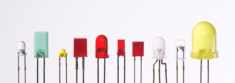
LEDs are produced in a variety of shapes and sizes. The color of the plastic lens is often the same as the actual color of light emitted, but not always. For instance, purple plastic is often used for infrared LEDs, and most blue devices have colorless housings. Modern high-power LEDs such as those used for lighting and backlighting are generally found in surface-mount technology (SMT) packages (not shown).
The main types of LEDs are miniature, high-power devices, and custom designs such as alphanumeric or multicolor.
High-power
.jpg)
High-power light-emitting diodes attached to an LED star base
Some well-known HP-LEDs in this category are the Nichia 19 series, Lumileds Rebel Led, Osram Opto Semiconductors Golden Dragon, and Cree X-lamp. As of September 2009, some HP-LEDs manufactured by Cree now exceed 105 lm/W.
Examples for Haitz's law—which predicts an exponential rise in light output and efficacy of LEDs over time—are the CREE XP-G series LED, which achieved 105 lm/W in 2009 and the Nichia 19 series with a typical efficacy of 140 lm/W, released in 2010.

*If you have wired up LEDs before, this explanation might seem overly simplistic. Consider yourself warned.

We have used LEDs once or twice before for simple applications, but I never really knew what I was doing, and since so many projects on instructables use LEDs, I thought I might as well teach myself and post about it too.
there could still be some use for a detailed step by step explanation about the basics of LEDs for anyone who could use it.
The first step was to buy some supplies and figure out what I would need to experiment with. For this project I ended up going to Radioshack because its close and a lot of people have access to it - but be warned their prices are really high for this kind of stuff and there are all kinds of low cost places to buy LEDs online.
To light up an LED you need at the very minimum the LED itself and a power supply. From what I have read from other LED instructables wiring in a resistor is almost always a good idea.
If you want to learn about what these materials are check out these wikipedia entries:
LEDs
Power supply
Resistors
Materials:
LEDs - I basically just reached into the drawer at Radioshack and pulled out anything that wasn't more than $1 or $2 per LED. I got:
2760307 5mm Red LED 1.7 V
2760351 5MM Yellow LED 2.1 V
2760036 Flasher Red LED 5 V
2760041 2 Pack Red LED 2.6 V
2760086 Jumbo Red LED 2.4V
Power Supply - I really didn't know what I would need to power them so I bought some 9V batteries and some 1.5V AA's. I figured that would allow me to mix and match and make enough different voltage combinations to make something light up - or at least burn those little suckers out in a puff of smelly plastic smoke.
Resistors - Again, I wasn't too sure what I would need in terms of resistors here either. Since I got a whole bunch of different LEDs with various voltages I knew that I would need a couple different types of resistors, so I just bought a variety pack of 1/2 Watt Carbon Film Resistors (2710306).
I gathered up a soldering gun, solder, needle nose pliers, electrical pliers, some primary wire and electrical tape too since I thought they might be useful.
Step 2: The LED

LEDs come in different sizes, brightnesses, voltages, colors and beam
patterns, but the selection at Radioshack is pretty small and so I just
picked up a couple different LEDs from what they had in a few different
brightnesses and voltages. I kept close track of what LED was what
voltage because I didn't want to accidentally send too much current
through one of the low voltage LEDs.
The first thing I did with the LEDs was figure out which wire
(its called an electrode) was positive and which was negative.
Generally speaking the longer wire is the positive electrode and the
shorter wire is the negative electrode.
You can also take a look inside the LED itself and see whats
going on. The smaller of the metal pieces inside the LED connects to
the positive electrode and the bigger one is the negative electrode (see
picture below). But be warned - in the LEDs I picked up I didn't
always find this to be true and some of the LEDs had the longer
electrode on the negative when it should be on the positive. Go figure -
its OK though, if it didn't light up I just flipped it around.
Once I knew what was positive and what was negative I just had to remember what the voltage of each LED was.
All my LEDs recommended 20mA of current. 20mA is standard for most LEDs.
Step 3: Power Supply

To make the power supplies I just soldered some wire onto the ends of the batteries I had bought so that I could easily attach the LEDs to them. The 9V battery served as my 9V power supply, one AA battery made a 1.5V power supply and three AA batteries bundled together made a 4.5V (1.5V + 1.5V + 1.5V = 4.5V) power supply. I didn't use alligator clips on the ends of the wire, but they would have been helpful here.
Step 4: Resistors

I opened up the assortment pack to find that resistors aren't labeled with what value they are. The pack said it contained a whole bunch of different resistors from 100 ohms to 1 Meg ohm so I set out to see what was what. When I poked around online I found that all resistors have a coding system on them that tells you what value they are.
Step 5: One LED, No Resistor

I thought that I would start as simply as I
possibly could - just one LED with no resistor. First I had to decide
what power source to use and which LED to light up. This may seem
obvious, but this was my first time through so I might as well be as
clear as possible...
LEDs require sufficient voltage to light them. Sometimes if you give them too little voltage they wont light at all, other times they will just shine dimly with low voltage. Too much voltage is bad and can burn out the LED instantaneously.
So ideally you would like the voltage of the LED to match the voltage of your power supply, or even be slightly less. To do this you can do a couple of things: change your power supply voltage, change the LED your using, or you can use a resistor that allows you use a higher voltage power supply with a lower voltage LED.
For now I just wanted to get one lit up so I chose my the power supply that had the lowest voltage - the single AA battery which outputs 1.5V.
I chose to light the red 1.7V LED since the battery outputs 1.5V and I knew I wouldn't kill the LED with too much power.
I wrapped my positive wire from the battery to the positive electrode of the LED and wrapped the negative wire from the battery to my negative electrode and presto - let there be LED light!
This first experiment was pretty easy to do - just some wire twisting and enough knowledge to know that the 1.5V power supply would light the 1.7V LED without need a resistor.
Step 6: One LED With a Resistor

It was just a coincidence that I bought an LED that was 1.7V and that it
ended up working being able to be powered by my 1.5V power supply
without the use of a resistor. For this second setup I decided to use
the same LED, but up my power supply to the three AA batteries wired
together which output 4.5V - enough power to burn out my 1.7V LED, so I
would have to use a resistor.
To figure out which resistor to use I used the formula:
R = (V1 - V2) / I
where:
V1 = power supply voltage
V2 = LED voltage
I = LED current (usually 20mA which is .02A)
Now there are lots of calculators online that will do this for you - and many other instructables reference this
as a good one, however, the math really isn't too hard and so I wanted
to go through the calculation myself and understand whats going on.
Again, my LED is 1.7V, it takes 20mA (which is .02 A) of current and my supply is 4.5V. So the math is...
R = (4.5V - 1.7V) / .02 A
R = 140 ohms
Once
I knew that I needed a resistor of 140 ohms to get the correct amount
of voltage to the LED I looked into my assortment package of resistors
to see if I could find the right one.
Knowing the value of a
resistor requires reading the code from the color bands on the resistor
itself. The package didn't come with a 140 ohm resistor but it did come
with a 150 ohm one. Its always better to use the next closest value
resistor greater than what you calculated. Using a lower value could
burn out your LED.
To figure out the color code you basically
break down the first two digits of the resistor value, use the third
digit to multiply the first two by and then assign the fourth digit as
an indicator of tolerance. That sounds a lot more difficult than it
really is.
Using the color to number secret decoder website found here, a 150ohm resistor should have the following color code...
Brown because the first digit in the value resistor I needed is 1
Green because the fifth digit is 5
Brown because in order to get to 150 you have to add one 0 to 15 to get to 150.
Gold - the resistors I got all have 5% tolerance and 5% is represented by gold
Check out the decoder page link above if this isn't making sense.
I
looked through all the resistors, found the one that was brown, green,
brown, gold, and wired it in line on the positive electrode of the LED.
(Whenever using a resistor on an LED it should get placed before the
LED on the positive electrode).
Low and behold, the LED lit up
once again. The 150 ohm resistor stopped enough of the 4.5V power
supply from reaching the 1.7V LED that it lit up safely and kept it from
burning out.
This is just the process that I went through to
figure out what resistor to use with my particular LED with my
particular power supply. You can easily use the formula above to figure
out what value resistor to use with whatever LED and power source you
happen to be using.
Step 7: Wiring Up Multiple LEDs in Series

Now that I knew how to wire one LED with various combinations of LED voltages and power supplies, it was time to explore how to light up multiple LEDs. When it comes to wiring more than one LED to a power supply there are two options. The first option is to wire them in series and the second is to wire them in parallel.
LEDs wired in series are connected end to end (the negative electrode of
the first LED connects to the positive electrode of the second LED and
the negative electrode of the second LED connects to the positive
electrode of the third LED and so on and so on...). The main advantage
of wiring things in series is that it distributes the total voltage of
the power source between all of the LEDs. What that means is that if I
had a 12V car battery, I could power 4, 3V LEDs (attaching a resistor to
each of them). Hypothetically this could also work to power 12, 1V
LEDs; 6, 2V LEDs; or even 1 12V LED if such a thing existed.
Ok, let's try wiring 2, 2.6V LEDs in series to the 9V power supply and run through the math.
R = (9V - 5.2V) / .02A
R = 190 Ohms
Next higher resistance value - 200 Ohms
Now
the variety package of resistors didn't come with a 190 or 200 Ohm
resistor, but it did come with other resistors which I could use to make
a 200 Ohm resistor. Just like LEDs, resistors can be wired together in
either series or parallel (see next step for an explanation on wiring
things together in parallel).
When same value resistors are
wired together in series you add their resistance. When same value
resistors are wired together in parallel you divide the value of the
resistor by the number of resistors wired together.
So, in the
most simplified sense, two 100 Ohm resistors wired together in series
will equal 1 200 Ohm resistor (100 + 100 = 200). Two 100 Ohm resistors
wired together in parallel will equal one 50 Ohm resistor (100 / 2 =
50).
Unfortunately, I learned this key point after I wired my
resistors together for the experiment. I had originally wanted to wire
two 100 Ohm resistors together to equal the 200 Ohms of resistance I
needed to protect my LEDs. Instead of wiring them in series, as it
should have been, I wired my resistors in parallel (did I mention I am
beginner with resistors?) So my resistors were only providing 50 Ohms
of resistance - which apparently worked out OK on my LEDs in the short
duration of the experiment. Having too much power getting to the LEDs
would probably burn them out in the long term. (Thanks beanwaur and
shark500 for pointing this out.)
I took my resistors and placed
them in front of the positive lead of the first LED that was wired in
series and hooked them up to the battery and once again, there was LED
light!
With three different combinations of LEDs and battery
power supplies and no puffs of plastic smoke yet things were looking
good - aside from my little confusion between wiring resistors in series
and in parallel.
Step 8: Wiring Up Multiple LEDs in Parallel

Unlike LEDs that are wired in series, LEDs wired in parallel use one
wire to connect all the positive electrodes of the LEDs your using to
the positive wire of the power supply and use another wire to connect
all the negative electrodes of the LEDs your using to the negative wire
of the power supply. Wiring things in parallel has some distinct
advantages over wiring things in series.
If you wire a whole
bunch of LEDs in parallel rather than dividing the power supplied to
them between them, they all share it. So, a 12V battery wired to four
3V LEDs in series would distribute 3V to each of the LEDs. But that
same 12V battery wired to four 3V LEDs in parallel would deliver the
full 12V to each LED - enough to burn out the LEDs for sure!
Wiring
LEDs in parallel allows many LEDs to share just one low voltage power
supply. We could take those same four 3V LEDs and wire them in parallel
to a smaller power supply, say two AA batteries putting out a total of
3V and each of the LEDs would get the 3V they need.
In short,
wiring in series divides the total power supply between the LEDs.
Wiring them in parallel means that each LED will receive the total
voltage that the power supply is outputting.
And finally, just
some warnings...wiring in parallel drains your power supply faster than
wiring things in series because they end up drawing more current from
the power supply. It also only works if all the LEDs you are using have
exactly the same power specifications. Do NOT mix and match different
types/colors of LEDs when wiring in parallel.
OK, now onto to actually doing the thing.
I decided to do two different parallel setups.
The
first one I tried was as simple as it could be - just two 1.7V LEDs
wired in parallel to a single 1.5V AA battery. I connected the two
positive electrodes on the LEDs to the positive wire coming from the
battery and connected the two negative electrodes on the LEDs to the
negative wire coming from the battery. The 1.7V LEDs didn't require a
resistor because the 1.5V coming from the battery was enough to light
the LED, but not more than the LEDs voltage - so there was no risk of
burning it out. (This set up is not pictured)
Both of the 1.7V
LEDs were lit by the 1.5V power supply, but remember, the were drawing
more current from the battery and would thus make the battery drain
faster. If there were more LEDs connected to the battery, they would
draw even more current from the battery and drain it even faster.
For
the second setup, I decided to put everything I had learned together
and wire the two LEDs in parallel to my 9V power supply - certainly too
much juice for the LEDs alone so I would have to use a resistor for
sure.
To figure out what value I should use I went back to the
trusty formula - but since they were wired in parallel there is a slight
change to the formula when it comes to the current - I.
R = (V1 - V2) / I
where:
V1 = supply voltage
V2 = LED voltage
I
= LED current (we had been using 20 mA in our other calculations but
since wiring LEDs in parallel draws more current I had to multiply the
current that one LED draws by the total number of LEDs I was using. 20
mA x 2 = 40 mA, or .04A.
And my values for the formula this time were:
R = (9V - 1.7V) / .04A
R = 182.5 Ohms
Again,
since the variety pack didn't come with that exact value resistor I
attempted to use the two 100 Ohm resistors bundled together in series to
make 200 Ohms of resistance. I ended up just repeating the mistake
that I made in the last step again though, and wired them together in
parallel by mistake and so the two 100 Ohm resistors only ended up
providing 50 Ohms of resistance. Again, these LEDs were particularly
forgiving of my mistake - and now I have learned a valuable lesson about
wiring resistors in series and in parallel.
One last note about
wiring LEDs in parallel - while I put my resistor in front of both LEDs
it is recommended that you put a resistor in front of each LED. This is
the safer better way to wire LEDs in parallel with resistors - and also
ensures that you don't make the mistake that I did accidentally.
The 1.7V LEDs connected to the 9V battery lit up - and my small adventure into LED land was completed.
Step 9: Extrapolation
While I didn't actually end up making anything besides a couple of lit
LEDs, this information can be used to make all kinds of cool things!
The take away concepts hopefully were:
- Power a whole bunch of different value LEDs using the same basic principals.
- Figure out what is the positive electrode and what is the negative electrode of an LED by looking at it and testing it.
- Use resistors, or combinations of resistors wired together in
series or in parallel to supply the correct amount of power to the LED.
- Make calculations to determine what resistor is needed using the formula, or using web sites that do it for you.
- Wire LEDs in series or in parallel depending on the application.
- Make LEDs light up!
This was the most basic kind of walk through for LEDs possible -
and I learned a whole lot along the way. LED arrays and wiring schemes
can get significantly more complicated - but for the most part, LEDs
are pretty simple to work with, and with relatively little knowledge I
was able to light them up - all be it if I sent a little too much juice
through them towards the end of the experiment. I don't fear the LED
now.

Luminescence
Luminescence is spontaneous emission of light by a substance not resulting from heat; it is thus a form of cold-body radiation. It can be caused by chemical reactions, electrical energy, subatomic motions or stress on a crystal. This distinguishes luminescence from incandescence, which is light emitted by a substance as a result of heating. Historically, radioactivity was thought of as a form of "radio-luminescence", although it is today considered to be separate since it involves more than electromagnetic radiation.

UV-photoluminescence in the microbiological diagnostics

Luminol and haemoglobin, an example of chemiluminescence
Types
The following are types of luminescence:- Chemiluminescence, the emission of light as a result of a chemical reaction
- Bioluminescence, a result of biochemical reactions in a living organism
- Electrochemiluminescence, a result of an electrochemical reaction
- Lyoluminescence, a result of dissolving a solid (usually heavily irradiated) in a liquid solvent
- Candoluminescence, is light emitted by certain materials at elevated temperatures, which differs from the blackbody emission expected at the temperature in question.
- Crystalloluminescence, produced during crystallization
- Electroluminescence, a result of an electric current passed through a substance
- Cathodoluminescence, a result of a luminescent material being struck by electrons
- Mechanoluminescence, a result of a mechanical action on a solid
- Triboluminescence, generated when bonds in a material are broken when that material is scratched, crushed, or rubbed
- Fractoluminescence, generated when bonds in certain crystals are broken by fractures
- Piezoluminescence, produced by the action of pressure on certain solids
- Sonoluminescence, a result of imploding bubbles in a liquid when excited by sound
- Photoluminescence, a result of absorption of photons
- Fluorescence, photoluminescence as a result of singlet–singlet electronic relaxation (typical lifetime: nanoseconds)
- Phosphorescence, photoluminescence as a result of triplet–singlet electronic relaxation (typical lifetime: milliseconds to hours)
- Raman emission, photoluminescence as a result of inelastic light scattering, (lifetime: nanoseconds)
- Radioluminescence, a result of bombardment by ionizing radiation
- Thermoluminescence, the re-emission of absorbed energy when a substance is heated
- Cryoluminescence, the emission of light when an object is cooled (an example of this is wulfenite)
Applications
- Light-emitting diodes (LEDs) emit light via electro-luminescence.
- Phosphors, materials that emit light when irradiated by higher-energy electromagnetic radiation or particle radiation
- Phosphor thermometry, measuring temperature using phosphorescence
- Thermoluminescence dating
- Thermoluminescent dosimeter
- Non-disruptive observation of processes within a cell.
Light-emitting diode
A light-emitting diode (LED) is a two-lead semiconductor light source. It is a p–n junction diode that emits light when activated. When a suitable current is applied to the leads, electrons are able to recombine with electron holes within the device, releasing energy in the form of photons. This effect is called electroluminescence, and the color of the light (corresponding to the energy of the photon) is determined by the energy band gap of the semiconductor. LEDs are typically small (less than 1 mm2) and integrated optical components may be used to shape the radiation pattern.
Appearing as practical electronic components in 1962, the earliest LEDs emitted low-intensity infrared light. Infrared LEDs are still frequently used as transmitting elements in remote-control circuits, such as those in remote controls for a wide variety of consumer electronics. The first visible-light LEDs were of low intensity and limited to red. Modern LEDs are available across the visible, ultraviolet, and infrared wavelengths, with very high brightness.
Early LEDs were often used as indicator lamps for electronic devices, replacing small incandescent bulbs. They were soon packaged into numeric readouts in the form of seven-segment displays and were commonly seen in digital clocks. Recent developments have produced LEDs suitable for environmental and task lighting. LEDs have led to new displays and sensors, while their high switching rates are useful in advanced communications technology.
LEDs have many advantages over incandescent light sources, including lower energy consumption, longer lifetime, improved physical robustness, smaller size, and faster switching. Light-emitting diodes are used in applications as diverse as aviation lighting, automotive headlamps, advertising, general lighting, traffic signals, camera flashes, lighted wallpaper and medical devices. They are also significantly more energy efficient and, arguably, have fewer environmental concerns linked to their disposal.
Unlike a laser, the color of light emitted from an LED is neither coherent nor monochromatic, but the spectrum is narrow with respect to human vision, and for most purposes the light from a simple diode element can be regarded as functionally monochromatic .
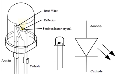
.svg)
Parts of a conventional LED. The flat bottom surfaces of the anvil and post embedded inside the epoxy act as anchors, to prevent the conductors from being forcefully pulled out via mechanical strain or vibration.

Close up image of a surface mount LED

A bulb-shaped modern retrofit LED lamp with aluminium heat sink, a light diffusing dome and E27 screw base, using a built-in power supply working on mains voltage
Discoveries and early devices

In 1936, Georges Destriau observed Electroluminescence could be produced when zinc sulphide (ZnS) powder is suspended in an insulator and an alternating electrical field is applied to it. In his publications, Destriau often referred to luminescence as Losev-Light. Destriau worked in the laboratories of Madame Marie Curie, also an early pioneer in the field of luminescence with research on radium.
Kurt Lehovec, Carl Accardo, and Edward Jamgochian explained these first light-emitting diodes in 1951 using an apparatus employing SiC crystals with a current source of battery or pulse generator and with a comparison to a variant, pure, crystal in 1953.
Rubin Braunstein of the Radio Corporation of America reported on infrared emission from gallium arsenide (GaAs) and other semiconductor alloys in 1955. Braunstein observed infrared emission generated by simple diode structures using gallium antimonide (GaSb), GaAs, indium phosphide (InP), and silicon-germanium (SiGe) alloys at room temperature and at 77 Kelvin.
In 1957, Braunstein further demonstrated that the rudimentary devices could be used for non-radio communication across a short distance. As noted by Kroemer Braunstein "…had set up a simple optical communications link: Music emerging from a record player was used via suitable electronics to modulate the forward current of a GaAs diode. The emitted light was detected by a PbS diode some distance away. This signal was fed into an audio amplifier and played back by a loudspeaker. Intercepting the beam stopped the music. We had a great deal of fun playing with this setup." This setup presaged the use of LEDs for optical communication applications.

A Texas Instruments SNX-100 GaAs LED contained in a TO-18 transistor metal case.
The first visible-spectrum (red) LED was developed in 1962 by Nick Holonyak, Jr. while working at General Electric. Holonyak first reported his LED in the journal Applied Physics Letters on December 1, 1962.[28][29] M. George Craford,[30] a former graduate student of Holonyak, invented the first yellow LED and improved the brightness of red and red-orange LEDs by a factor of ten in 1972. In 1976, T. P. Pearsall created the first high-brightness, high-efficiency LEDs for optical fiber telecommunications by inventing new semiconductor materials specifically adapted to optical fiber transmission wavelengths.
Initial commercial development
The first commercial LEDs were commonly used as replacements for incandescent and neon indicator lamps, and in seven-segment displays, first in expensive equipment such as laboratory and electronics test equipment, then later in such appliances as TVs, radios, telephones, calculators, as well as watches (see list of signal uses). Until 1968, visible and infrared LEDs were extremely costly, in the order of US$200 per unit, and so had little practical use. The Monsanto Company was the first organization to mass-produce visible LEDs, using gallium arsenide phosphide (GaAsP) in 1968 to produce red LEDs suitable for indicators. Hewlett-Packard (HP) introduced LEDs in 1968, initially using GaAsP supplied by Monsanto. These red LEDs were bright enough only for use as indicators, as the light output was not enough to illuminate an area. Readouts in calculators were so small that plastic lenses were built over each digit to make them legible. Later, other colors became widely available and appeared in appliances and equipment. In the 1970s commercially successful LED devices at less than five cents each were produced by Fairchild Optoelectronics. These devices employed compound semiconductor chips fabricated with the planar process invented by Dr. Jean Hoerni at Fairchild Semiconductor. The combination of planar processing for chip fabrication and innovative packaging methods enabled the team at Fairchild led by optoelectronics pioneer Thomas Brandt to achieve the needed cost reductions. LED producers continue to use these methods.
LED display of a TI-30 scientific calculator (ca. 1978), which uses plastic lenses to increase the visible digit size
Blue LED
Blue LEDs were first developed by Herbert Paul Maruska at RCA in 1972 using gallium nitride (GaN) on a sapphire substrate. SiC-types were first commercially sold in the United States by Cree in 1989. However, neither of these initial blue LEDs were very bright.The first high-brightness blue LED was demonstrated by Shuji Nakamura of Nichia Corporation in 1994 and was based on InGaN.[42][43] In parallel, Isamu Akasaki and Hiroshi Amano in Nagoya were working on developing the important GaN nucleation on sapphire substrates and the demonstration of p-type doping of GaN. Nakamura, Akasaki, and Amano were awarded the 2014 Nobel prize in physics for their work.[44] In 1995, Alberto Barbieri at the Cardiff University Laboratory (GB) investigated the efficiency and reliability of high-brightness LEDs and demonstrated a "transparent contact" LED using indium tin oxide (ITO) on (AlGaInP/GaAs).
In 2001 and 2002, processes for growing gallium nitride (GaN) LEDs on silicon were successfully demonstrated. In January 2012, Osram demonstrated high-power InGaN LEDs grown on silicon substrates commercially, and GaN-on-silicon LEDs are in production at Plessey Semiconductors. As of 2017, some manufacturers are using SiC as the substrate for LED production, but sapphire is more common, as it has the most similar properties to that of gallium nitride, reducing the need for patterning the sapphire wafer. (Patterned wafers are known as epi wafers.) Samsung, the University of Cambridge, and Toshiba are performing research into GaN on Si(licon) LEDs. Toshiba has stopped research, possibly due to low yields. Some opt towards epitaxy, which is difficult on silicon, while others, like the University of Cambridge, opt towards a multi layer structure, in order to reduce (crystal) lattice mismatch and different thermal expansion ratios, in order to avoid cracking of the led chip at high temperatures (e.g. during manufacturing), reduce heat generation and increase luminous efficiency. Epitaxy (or patterned sapphire) can be carried out with Nanoimprint lithography.
White LEDs and the illumination breakthrough
Even though white light can be created using individual red, green and blue LEDs, perhaps using a single SMD (Surface Mount Device) or through-hole RGB LED, this setup results in poor color rendering or CRI, due to the fact that virtually only 3 wavelengths of light are being emitted, so the attainment of high efficiency in blue LEDs was quickly followed by the development of the first white LED. In this device a Y3Al
5O
12:Ce (known as "YAG") cerium doped phosphor coating on the emitter absorbs some of the blue emission and produces yellow light through fluorescence. The combination of that yellow with remaining blue light appears white to the eye. However, using different phosphors (fluorescent materials) it also became possible to instead produce green and red light through fluorescence. The resulting mixture of red, green and blue is not only perceived by humans as white light but is superior for illumination in terms of color rendering, whereas one cannot appreciate the color of red or green objects illuminated only by the yellow (and remaining blue) wavelengths from the YAG phosphor.

Illustration of Haitz's law, showing improvement in light output per LED over time, with a logarithmic scale on the vertical axis
Light output and efficiency of blue and near-ultraviolet LEDs rose as the cost of reliable devices fell. This led to relatively high-power white-light LEDs for illumination, which are replacing incandescent and fluorescent lighting.
Experimental white LEDs have been demonstrated to produce 303 lumens per watt of electricity (lm/w); some can last up to 100,000 hours. However, commercially available LEDs have an efficiency of up to 223 lm/w. Compared to incandescent bulbs, this is not only a huge increase in electrical efficiency but – over time – a similar or lower cost per bulb. The LED chip is encapsulated inside a small, plastic, white mold. It can be encapsulated using resin, silicone, or epoxy containing (powdered) Cerium doped YAG phosphor. After allowing the solvents to evaporate, the LEDs are often tested, and placed on tapes for SMT placement equipment for use in LED light bulb production. Encapsulation is performed after probing, dicing, die transfer from wafer to package, and wire bonding or flip chip mounting, perhaps using Indium tin oxide, a transparent electrical conductor. In this case, the bond wire(s) are attached to the ITO film that has been deposited in the LEDs.
The YAG phosphor in the LED's encapsulation compound is why white LEDs look yellow when off. Some LED light bulbs use a single plastic cover with YAG phosphor (remote phosphor) for several blue LEDs instead of using a diffuser and single chip white LEDs. Remote phosphor LED light bulbs may have behind the plastic cover a white plastic reflector. Others shape the remote phosphor as a dome, or sphere, and place it atop a single PCB containing blue LEDs; this assembly may be behind a frosted glass or plastic cover. The PCB is often installed atop a pillar, which is lined with white plastic.
Working principle

The inner workings of an LED, showing circuit (top) and band diagram (bottom)
The electrons dissipate energy in the form of heat for silicon and germanium diodes but in gallium arsenide phosphide (GaAsP) and gallium phosphide (GaP) semiconductors, the electrons dissipate energy by emitting photons. If the semiconductor is translucent, the junction becomes the source of light as it is emitted, thus becoming a light-emitting diode. However, when the junction is reverse biased, the LED produces no light and—if the potential is great enough, the device is damaged.
Technology

I-V diagram for a diode.
An LED begins to emit light when more than 2 or 3 volts is applied. The
reverse bias region uses a different vertical scale from the forward
bias region to show that the leakage current is nearly constant with
voltage until breakdown occurs. In forward bias, the current is small
but increases exponentially with voltage.
Physics
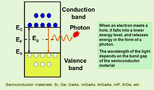
The LED consists of a chip of semiconducting material doped with impurities to create a p-n junction. As in other diodes, current flows easily from the p-side, or anode, to the n-side, or cathode, but not in the reverse direction. Charge-carriers—electrons and holes—flow into the junction from electrodes with different voltages. When an electron meets a hole, it falls into a lower energy level and releases energy in the form of a photon.The wavelength of the light emitted, and thus its color, depends on the band gap energy of the materials forming the p-n junction. In silicon or germanium diodes, the electrons and holes usually recombine by a non-radiative transition, which produces no optical emission, because these are indirect band gap materials. The materials used for the LED have a direct band gap with energies corresponding to near-infrared, visible, or near-ultraviolet light.
LED development began with infrared and red devices made with gallium arsenide. Advances in materials science have enabled making devices with ever-shorter wavelengths, emitting light in a variety of colors.
LEDs are usually built on an n-type substrate, with an electrode attached to the p-type layer deposited on its surface. P-type substrates, while less common, occur as well. Many commercial LEDs, especially GaN/InGaN, also use sapphire substrate.
Refractive index

Idealized
example of light emission cones in a simple square semiconductor, for a
single point-source emission zone. The left illustration is for a
translucent wafer, while the right illustration shows the half-cones
formed when the bottom layer is opaque. The light is actually emitted
equally in all directions from the point-source, but can only escape
perpendicular to the semiconductor's surface and some degrees to the
side, which is illustrated by the cone shapes. When the critical angle
is exceeded, photons are reflected internally. The areas between the
cones represent the trapped light energy wasted as heat.

Most materials used for LED production have very high refractive indices. This means that much of the light is reflected back into the material at the material/air surface interface. Thus, light extraction in LEDs
is an important aspect of LED production, subject to much research and
development. The light emission cones of a real LED wafer are far more
complex than a single point-source light emission. The light emission
zone is typically a two-dimensional plane between the wafers. Every atom
across this plane has an individual set of emission cones. Drawing the
billions of overlapping cones is impossible, so this is a simplified
diagram showing the extents of all the emission cones combined. The
larger side cones are clipped to show the interior features and reduce
image complexity; they would extend to the opposite edges of the
two-dimensional emission plane.
In general, a flat-surface uncoated LED semiconductor chip emits light only perpendicular to the semiconductor's surface, and a few degrees to the side, in a cone shape referred to as the light cone, cone of light, or the escape cone. The maximum angle of incidence is referred to as the critical angle. When the critical angle is exceeded, photons no longer escape the semiconductor but are, instead, reflected internally inside the semiconductor crystal as if it were a mirror.
Internal reflections can escape through other crystalline faces if the incidence angle is low enough and the crystal is sufficiently transparent to not re-absorb the photon emission. But for a simple square LED with 90-degree angled surfaces on all sides, the faces all act as equal angle mirrors. In this case, most of the light can not escape and is lost as waste heat in the crystal.
A convoluted chip surface with angled facets similar to a jewel or fresnel lens can increase light output by distributing light perpendicular to the chip surface and far to the sides of the photon emission point.
The ideal shape of a semiconductor with maximum light output would be a microsphere with the photon emission occurring at the exact center, with electrodes penetrating to the center to contact at the emission point. All light rays emanating from the center would be perpendicular to the entire surface of the sphere, resulting in no internal reflections. A hemispherical semiconductor would also work, with the flat back-surface serving as a mirror to back-scattered photons.
Transition coatings
After the doping of the wafer, it is usually cut apart into individual dies. Each die is commonly called a chip.Many LED semiconductor chips are encapsulated or potted in clear or colored molded solid plastic. The plastic encapsulation has three purposes:
- Mounting the semiconductor chip in devices is easier to accomplish.
- The tiny fragile electrical wiring is physically supported and protected from damage.
- The plastic acts as a refractive intermediary between the relatively high-index semiconductor and low-index open air.
Efficiency and operational parameters
Typical indicator LEDs are designed to operate with no more than 30–60 milliwatts (mW) of electrical power. Around 1999, Philips Lumileds introduced power LEDs capable of continuous use at one watt. These LEDs used much larger semiconductor die sizes to handle the large power inputs. Also, the semiconductor dies were mounted onto metal slugs to allow for greater heat dissipation from the LED die.One of the key advantages of LED-based lighting sources is high luminous efficacy. White LEDs quickly matched and overtook the efficacy of standard incandescent lighting systems. In 2002, Lumileds made five-watt LEDs available with luminous efficacy of 18–22 lumens per watt (lm/W). For comparison, a conventional incandescent light bulb of 60–100 watts emits around 15 lm/W, and standard fluorescent lights emit up to 100 lm/W.
As of 2012, Philips had achieved the following efficacies for each color. The efficiency values show the physics – light power out per electrical power in. The lumen-per-watt efficacy value includes characteristics of the human eye and is derived using the luminosity function.
| Color | Wavelength range (nm) | Typical efficiency coefficient | Typical efficacy (lm/W) | |
|---|---|---|---|---|
| Red | 620 < λ < 645 | 0.39 | 72 | |
| Red-orange | 610 < λ < 620 | 0.29 | 98 | |
| Green | 520 < λ < 550 | 0.15 | 93 | |
| Cyan | 490 < λ < 520 | 0.26 | 75 | |
| Blue | 460 < λ < 490 | 0.35 | 37 |
These efficiencies are for the light-emitting diode only, held at low temperature in a lab. Since LEDs installed in real fixtures operate at higher temperature and with driver losses, real-world efficiencies are much lower. United States Department of Energy (DOE) testing of commercial LED lamps designed to replace incandescent lamps or CFLs showed that average efficacy was still about 46 lm/W in 2009 (tested performance ranged from 17 lm/W to 79 lm/W) .
Lifetime and failure
Solid-state devices such as LEDs are subject to very limited wear and tear if operated at low currents and at low temperatures. Typical lifetimes quoted are 25,000 to 100,000 hours, but heat and current settings can extend or shorten this time significantly. One way to cool down the LED and use the energy efficiently, is to blink the LED in order to gain biomass for example in microalgae cultivation. It is important to note that these projections are based on a standard test that may not accelerate all the potential mechanisms that can induce failures in LEDs.The most common symptom of LED (and diode laser) failure is the gradual lowering of light output and loss of efficiency. Sudden failures, although rare, can also occur. Early red LEDs were notable for their short service life. With the development of high-power LEDs, the devices are subjected to higher junction temperatures and higher current densities than traditional devices. This causes stress on the material and may cause early light-output degradation. To quantify useful lifetime in a standardized manner, some suggest using L70 or L50, which are runtimes (typically in thousands of hours) at which a given LED reaches 70% and 50% of initial light output, respectively.
Whereas in most previous sources of light (incandescent lamps, discharge lamps, and those that burn combustible fuel, e.g. candles and oil lamps) the light results from heat, LEDs only operate if they are kept cool enough. The manufacturer commonly specifies a maximum junction temperature of 125 or 150 °C, and lower temperatures are advisable in the interests of long life. At these temperatures, relatively little heat is lost by radiation, which means that the light beam generated by an LED is cool.
The waste heat in a high-power LED (which as of 2015 can be less than half the power that it consumes) is conveyed by conduction through the substrate and package of the LED to a heat sink, which gives up the heat to the ambient air by convection. Careful thermal design is, therefore, essential, taking into account the thermal resistances of the LED’s package, the heat sink and the interface between the two. Medium-power LEDs are often designed to solder directly to a printed circuit board that contains a thermally conductive metal layer. (Often, it is a PCB with a white Solder mask (white pcb) and a ~1mm thick aluminum backing.) High-power LEDs are packaged in large-area ceramic packages that attach to a metal heat sink—the interface being a material with high thermal conductivity (thermal grease, phase-change material, thermally conductive pad, or thermal adhesive).
If an LED-based lamp is installed in an unventilated luminaire, or a luminaire is located in an environment that does not have free air circulation, the LED is likely to overheat, resulting in reduced life or early catastrophic failure. Thermal design is often based on an ambient temperature of 25 °C (77 °F). LEDs used in outdoor applications, such as traffic signals or in-pavement signal lights, and in climates where the temperature within the light fixture becomes very high, could experience reduced output or even failure.
Since LED efficacy is higher at low temperatures, LED technology is well suited for supermarket freezer lighting. Because LEDs produce less waste heat than incandescent lamps, freezer tube lighting use can save on refrigeration costs as well. However, they may be more susceptible to frost and snow buildup than incandescent lamps, so some LED lighting systems have been designed with an added heating circuit. Additionally, research has developed heat sink technologies that transfer heat produced within the junction to appropriate areas of the light fixture
Blue and ultraviolet

Blue LEDs
 | |
In the late 1980s, key breakthroughs in GaN epitaxial growth and p-type doping ushered in the modern era of GaN-based optoelectronic devices. Building upon this foundation, Theodore Moustakas at Boston University patented a method for producing high-brightness blue LEDs using a new two-step process. Two years later, in 1993, high-brightness blue LEDs were demonstrated again by Shuji Nakamura of Nichia Corporation using a gallium nitride growth process similar to Moustakas's. Both Moustakas and Nakamura were issued separate patents, which confused the issue of who was the original inventor (partly because although Moustakas invented his first, Nakamura filed first). This new development revolutionized LED lighting, making high-power blue light sources practical, leading to the development of technologies like Blu-ray, as well as allowing the bright high-resolution screens of modern tablets and phones.[citation needed]
Nakamura was awarded the 2006 Millennium Technology Prize for his invention. Nakamura, Hiroshi Amano and Isamu Akasaki were awarded the Nobel Prize in Physics in 2014 for the invention of the blue LED. In 2015, a US court ruled that three companies (i.e. the litigants who had not previously settled out of court) that had licensed Nakamura's patents for production in the United States had infringed Moustakas's prior patent, and ordered them to pay licensing fees of not less than 13 million USD.
By the late 1990s, blue LEDs became widely available. They have an active region consisting of one or more InGaN quantum wells sandwiched between thicker layers of GaN, called cladding layers. By varying the relative In/Ga fraction in the InGaN quantum wells, the light emission can in theory be varied from violet to amber. Aluminium gallium nitride (AlGaN) of varying Al/Ga fraction can be used to manufacture the cladding and quantum well layers for ultraviolet LEDs, but these devices have not yet reached the level of efficiency and technological maturity of InGaN/GaN blue/green devices. If un-alloyed GaN is used in this case to form the active quantum well layers, the device emits near-ultraviolet light with a peak wavelength centred around 365 nm. Green LEDs manufactured from the InGaN/GaN system are far more efficient and brighter than green LEDs produced with non-nitride material systems, but practical devices still exhibit efficiency too low for high-brightness applications.
With nitrides containing aluminium, most often AlGaN and AlGaInN, even shorter wavelengths are achievable. Ultraviolet LEDs in a range of wavelengths are becoming available on the market. Near-UV emitters at wavelengths around 375–395 nm are already cheap and often encountered, for example, as black light lamp replacements for inspection of anti-counterfeiting UV watermarks in some documents and paper currencies. Shorter-wavelength diodes, while substantially more expensive, are commercially available for wavelengths down to 240 nm. As the photosensitivity of microorganisms approximately matches the absorption spectrum of DNA, with a peak at about 260 nm, UV LED emitting at 250–270 nm are expected in prospective disinfection and sterilization devices. Recent research has shown that commercially available UVA LEDs (365 nm) are already effective disinfection and sterilization devices. UV-C wavelengths were obtained in laboratories using aluminium nitride (210 nm), boron nitride (215 nm) and diamond (235 nm).
RGB

RGB-SMD-LED
LED Controllers and LED Display Brightness Controller Circuit


Even if you are designing a microcontroller-based LED display system, often it may calls for a manual option to control brightness of the LED display unit. On the otherhand, if it is based on discrete components, such an option is a crucial requirement. Here is an economical solution for such situations. The visible brightness of an LED display can be continuously varied by applying a pulsed-signal and varying its duty cycle. Usually, almost all 7-segment decoder ICs have a blanking input (RBI) connection to imply this type of brightness control. Because, the frequency in picture is above 50 Hz, unwanted flickering effect will not be noticeable.
In the practical world, is a very popular CMOS IC used with 7-segment LED displays. consists of a 5-stage Johnson decade counter and an output decoder which converts the Johnson code to a 7-segment decoded output for driving one stage in a numerical display. This IC is particularly advantageous in display applications where low power dissipation and/or low package count is important. Another one is the TTL IC 74LS47 which is a BCD decoder/driver for seven segment common anode (CA) displays. Note that, the IC 74LS48 also makes the same work, but designed for seven segment common cathode (CC) displays. CD4511 is the CMOS version BCD decoder/driver for seven segment common cathode displays, with latch ability.

Pin assignments of popular integrated 7-segment display drivers
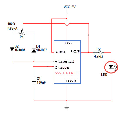
The solution described here is nothing but a simple add-on, built around the 555 chip (IC1) wired in ‘freerunning’ mode. Modified configuration using the 1N4148 diode (D1) provides a control over duty cycle without changing the output pulse frequency. As a consequence, the output frequency of 555 remains unaffected while its duty cycle is varied over a wide range by the 100K brightness control potetntiometer (P1). Output of the 555 IC (pin 3) can be applied to the decoder’s blanking input through the 2N2222 driver transistor (T1).

LED Display Brightness Controller Schematic
Pointer:
According to datasheets, in CD4511, when the input of the light test (LT) is activated in LOW, regardless the values of the rest of the inputs, all the segments of the display are lit up. When the blackening input (BI) gets activated in LOW with the light test input HIGH and regardless of the values of the rest of the inputs all the segments of the display are turned off (blackened). Similarly, in 74LS4X, when the light test input (LT) is activated in LOW, all the segments (a-g) of the display are lit up. The terminal BI/RBO functions as an input or an output. It becomes an output when the input RBI is activated in LOW. When the blackening input BI is activated (LOW), the display is blackened, meaning that the outputs become OFF. By activating the RBI input (LOW), the terminal BI/RBO changes into a blackening output RBO and is turned into LOW. Note that, ‘blanking’ means none of the segments of the LED display is turned on.
Note: This is an unorthodox attempt to draw your attention to the working of 7-segment LED display driver ICs, especially their ripple blanking input/output (RBI/RBO) features.
LED Driver with 555 Timer

This simple circuit allows us to drive up to seven LEDs by using a single NiMH (Nickel Metal Hydride) AA cell. The circuit produces voltage pulses at a much higher level than the input supply voltage by pulsing the 220 uH inductor. The inductor must be a high Q (Q>90) power inductor. When the input is 1.25 V and the LEDs are connected, the voltage pulse level will be 23V.
The LED driver uses a CMOS 555 timer since it operated with low voltages and can work for about 190 hours when using a single NiMH battery cell rated at 2000 mAh. The 555 timer drives the transistor at 222 kHz rate.
The LED driver uses a CMOS 555 timer since it operated with low voltages and can work for about 190 hours when using a single NiMH battery cell rated at 2000 mAh. The 555 timer drives the transistor at 222 kHz rate.
The seven LED groups can be connected paralelly if their forward voltages match. If not, the LED group with the lowest forward voltage value will dim out the other group(s). This parallel connection will not affect the total current drawn from the battery but it will reduce the brightness of the LEDs.

LED Driver Circuit Schematic
When a single 1.25V cell is used, the seven LED group will draw about 8mA from the battery. When the input value increases to 2.5V, the total drawn current will be 20mA.
PWM LAMP DIMMER USING NE555 TIMER

Introduction
In this project, we will see a PWM based LED Dimmer using 555 Timer IC. The main principle of this circuit is to generate a Pulse Width Modulation PWM Signal with the help of the good old reliable 555 Timer IC and vary the power being delivered to the LEDs and hence achieving the effect of LED Dimming.
The Pulse Width Modulation (PWM) plays an important role in controlling the a lot of circuits. If you want to control the speed of the motor, PWM plays a key role. Here, in our project, the PWM Technique is used for dimming the LEDs.
Using PWM technique, the mount of power delivered to a device is varied and hence, if we can control the pulse width of the signal, we can easily control the device like making a simple DC Motor to rotate slow or fast or to dim the intensity of an LED.
Block Diagram of LED Dimmer using 555
The following image depicts the block diagram of the PWM based LED Dimmer using 555 Timer IC.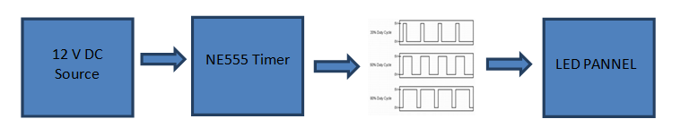
A 12V DC source is used to power the entire circuit including the 555 timer IC and the LEDs. The 555 timer is used to generate a PWM signal with the help of a few passive components.
The generated PWM Signal is then applied to a bunch of LEDs and based on the Duty Cycle of the PWM Signal, the intensity of the LEDs can be high or low.
A Brief Note on 555 Timer IC
The 555 Timer is an 8-pin Integrated Circuit available in Dual-in-Line Package originally developed by Signetics. It is one of the most popular ICs and is used for a variety of applications like Timer, Oscillator and Pulse Generation.
Pin Diagram of the 555 Timer IC is shown in the following image. The pin 8, which is the VCC pin, is used to give the main supply voltage to the IC. The operating voltage may vary from 3v to 15V. Pins 2, 6 and 7 are the Trigger, Threshold and the Discharge Pins.
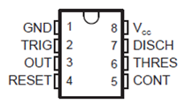
Pin 4 is the Reset pin and it is used to reset the complete IC. It is an active LOW Pin. The output of the IC can be taken from the out pin i.e. the pin 3. Pin 5 is the Control Pin.
The 555 Timer IC can work in three different modes of operation: Astable, Monostable and Bistable operations. It has features like timing for micro seconds through hours, adjustable duty cycles and ability work in various voltage levels etc. It has a wide range of applications like lamp dimmers, motor control, joysticks etc.
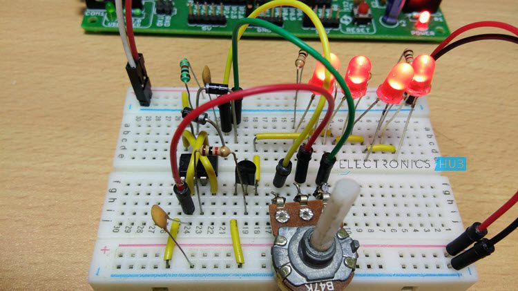
Circuit Diagram of PWM LED Dimmer Using 555
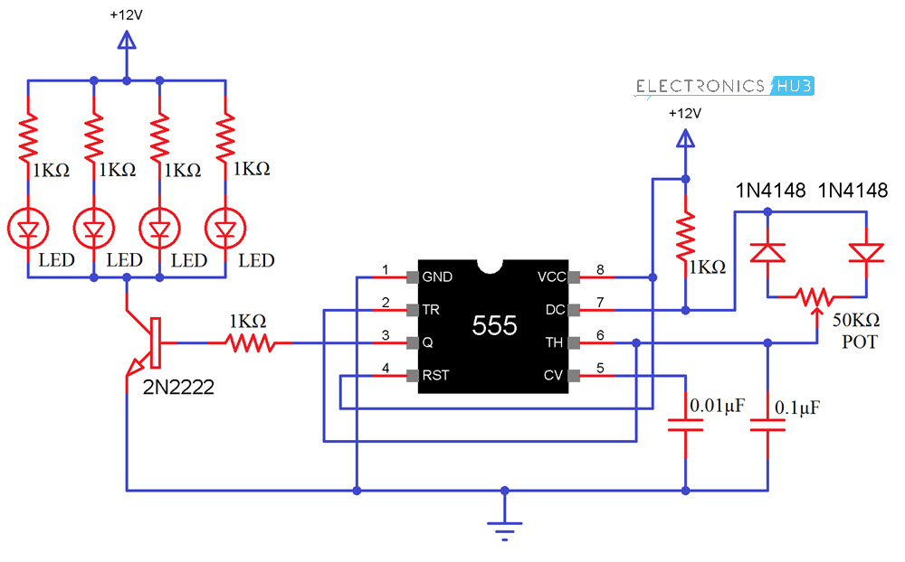
Components Required
- 555 Timer IC
- 1KΩ Resistor x 6
- Red LEDs x 4
- 2N2222 NPN Transistor
- 0.1μF Capacitor
- 0.01μF Capacitor
- 50KΩ Potentiometer
- 1N4148 Diodes
- 12V Power Supply
- Mini Breadboard
Circuit Design
- The 12V DC supply is given to the VCC Pin for operating voltage of 555 timer. The reset pin also directly connected to the 12V as shown in the circuit diagram. For resetting the IC, in case of an error while circuit is working, connect the RESET pin to GND for a Second and then connect it back to 12V.
- Pin 5 or the voltage control pin is not used in this application. Hence, a decoupling capacitor of 0.01μF is connected between pin 5 and GND.
- The Trigger pin (Pin 2) and threshold pin (pin 6) are shorted and the Wiper Terminal of the POT is connected here. Also, a 0.1μF Capacitor is connected between Pin 6 (or Pin 2) and GND.
- Now, one terminal of the POT is connected to anode of a Diode (preferably 1N4148) while the other terminal of the POT is connected to cathode of another diode.
- The other ends of both these diodes are connected to the Discharge Pin i.e. Pin 7. Also, a 1KΩ Resistor is connected between Pin 7 and VCC.
- The OUT pin is connected to the LED panel through the transistor.
Working of PWM LED Dimmer using 555
Here in this project, the 555 Timer is made to operate in the Astable Multivibrator Mode. The 1KΩ Resistor, the 50KΩ POT and the 0.1μF Capacitor connected with respect to Pins 2, 6 and 7 will play an important role.
Based on the charge and discharge timings of the Capacitor, a PWM Signal is generated at the OUT Pin i.e. Pin 3 of the 555 Timer IC. The output of the 555, which is taken form pin 3, is connected to the led panel through the NPN Transistor (2N2222 is used here) and a 1KΩ resistor.
The 1KΩ resistor is used to limit the base current of the transistor and transistor is used as an amplifier to limit or enhance the current which is given to the LED panel.
Auto Night Lamp Circuits
We usually turn ON the lights in our houses and offices manually. We need to turn ON the lights only when it is dark. So, how will that be if we make a circuit which turns ON the lights automatically when it is dark? In this article, we shall see how to automatically turns ON our domestic lights automatically when it is dark.Auto Night Lamp Using High Power LED
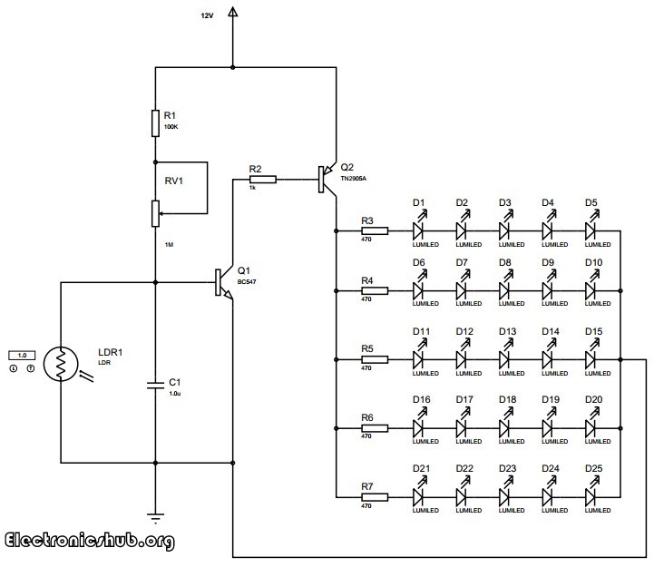
Auto Night Lamp Using High Power LEDs is a circuit which turns ON the LED lights interfaced to it at night time and it turns OFF the lights automatically when it is day. Usage of LEDs is growing day by day due to the advantages they provide compared to the conventional filament bulbs or fluorescent lamps. They provide good quality of white light with a better intensity compared to others. They also consume less power compared to their alternatives.
This circuit explain the light intensity control of night lamp using high power LEDS.The element which is used for sensing light in the circuit is the light dependent resistor. The resistance of the light dependent resistor depends on the light incident on it. If the intensity of light incident on it is more, then the resistance of the circuit decreases. If the intensity of light incident on it decreases, then the resistance of the device increases. We are making use of this property of the light dependent resistor to detect the light and thereby operate the LEDs. We are arranging twenty five light emitting diodes in an array such that five LEDs are in series and five such series LEDs are arranged in parallel.
Circuit Diagram of Auto Intensity Control of LED Lights
Working
The transistors are used in saturation mode. They are used as electronic switches in this mode. The transistor BC547 is a general purpose NPN transistor which is used to further switch the LEDs. This is a power transistor with a heat sink. The heat sink helps the transistor to dissipate the generated heat into air so that the transistor can handle higher power loads than it can do without the heat sink.
The entire circuit along with the LEDs is powered by a 12V DC power supply. A battery based DC power supply is usually preferred. However, you can use a ac rectified and regulated power supply.
The LEDs used in the circuit are high powered white LEDs. The intensity of light produced by these LEDs equals an ordinary fluorescent bulb. The lighting produced is sufficient for reading or to do any other daily activity. The circuit can be assembled on a printed circuit board with all the components neatly arranged and the LEDs placed in order. Try to place the LEDs maintaining a distance of about 1 cm between the LEDs so that the the lighting will be well distributed in your room.
Intelligent Unambiguous Night Lamp Switcher
While making a night lamp switcher, there are many aspects which needs to be taken into consideration without which there is a possibility of destroying the home appliances and lights. In this circuit, strict measures are taken to ensure that the lights to be operated are not damaged because of switching. In general, if we make a simple automatic night lamp switcher, it may turn ON the lights when it is dark. But here comes a problem. When the level of darkness is approaching, the circuit may get successive signals of dark and light with little time intervals. This may cause the circuit to repeatedly turn ON and OFF the lights at a high frequency which can possibly damage our lights within a few minutes or hours. This happens every time at evening as well as in the morning when the light intensity crosses a value for which our circuit is sensitive and toggles the switch.
In this circuit, it is not only a simple automatic light switching circuit, but also that it avoids repeated frequent switching of the devices which is usually ignored in most similar circuits but may have a detrimental effect on our operating devices. In this case, the lights. This is why the circuit is named as intelligent unambiguous night lamp as it intelligently switches the lights by avoiding repeated switching caused by unambiguity.
Circuit Diagram for Unambiguous Night Lamp Switcher
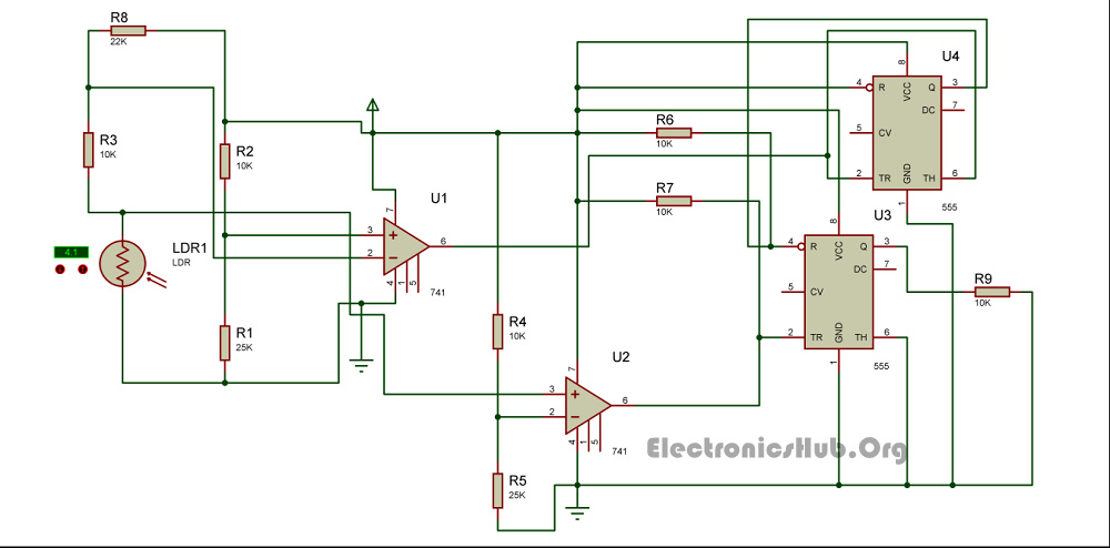
Unambiguous Night Lamp Switch Circuit Diagram – ElectronicsHub.Org
How to Operate this Night Lamp Switcher Circuit?
The circuit has two photo sensing devices which detect two levels of intensities. Light Dependant Resistors are used as photosensitive devices in this circuit. The light dependent resistor used with an op-amp as comparator detects the level of light intensity. The U1 IC 741 produces an output which is the first light intensity and the U2 IC741 detects the second light intensity. These two light intensities are used to calculate when the lights should be On and when they should be Off without producing unambiguous signals.
The two light detecting modules are arranged in such a way that when the first light intensity (dark point 1) is detected, the circuit turns On the relay and hence the lights will turn On. The circuit will turn Off the relay back again when both the light detecting modules detect light. This makes it eliminate ambiguities. There may be simpler circuits which detect darkness and turn On the lights but most of them fail to eliminate undesired repetitive switching. This circuit does a wonderful job by eliminating undesired switching effects.
The 555 IC U3 is in the bistable mode whereas the IC U4 acts as a buffer. The output of first IC 741 is given to the reset pin of the bistable IC whereas the output of second light detecting module with IC 741 is given to the set input of the bistable multivibrator.
Remote Control for Home Appliances
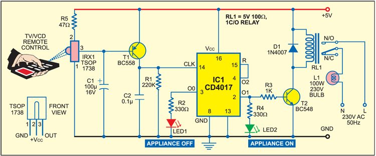
The influx of the Internet of things (IoT) devices has created a huge demand for connecting everything to everything. In the same race, this remote control for home appliances lets you connect your regular everyday appliances to be controlled by a remote. All you have to do is connect this circuit to any of your home appliances (lamp, fan, radio, etc) and you are good to go. The appliance can now be controlled by a remote control working at the designated frequency. The circuit can be activated from up to 10 metres.
Remote control for home appliances: Working Basics
The 38kHz infrared (IR) rays generated by the remote control are received by IR receiver module TSOP1738 of the circuit. Pin 1 of TSOP1738 is connected to ground, pin 2 is connected to the power supply through resistor R5 and the output is taken from pin 3. The output signal is amplified by transistor T1 (BC558).
The amplified signal is fed to clock pin 14 of decade counter IC CD4017 (IC1). Pin 8 of IC1 is grounded, pin 16 is connected to Vcc and pin 3 is connected to LED1 (red), which glows to indicate that the appliance is ‘off.’
The output of IC1 is taken from its pin 2. LED2 (green) connected to pin 2 is used to indicate the ‘on’ state of the appliance. Transistor T2 (BC548) connected to pin 2 of IC1 drives relay RL1. Diode 1N4007 (D1) acts as a freewheeling diode. The appliance to be controlled is connected between the pole of the relay and neutral terminal of mains. It gets connected to live terminal of AC mains via normally opened (N/O) contact when the relay energises.
Circuit Diagram

Working of Bipolar LED Driver Circuit
A LED driver or bipolar LED driver is an electrical circuit which a regulated amount of current and voltage to a LED or LED lamp. A LED lamp is a light that contains an arrangement of LEDs configured in an electrical circuit that is designed to operate efficiently. Bipolar LED driver circuits are power supplies optimized for LEDs and are generally known as “LED drivers”.
The LED drivers receive power from main alternating current (AC) source (primary voltage). The driver rectifies this primary voltage to generate a constant DC voltage on the secondary side to drive the LED lamp. The LED drivers can have bulky iron core transformers to step down the main high voltage to a lower voltage for the LED lamp (12V for example).
Most households use a power inverter to step down the voltage for the LED lamp because of their lower cost and small form factor.
The Basic Structure of Bipolar LED
Light-emitting diodes (LEDs) are two terminal semiconductor devices. A LED’s PN-junction releases photons when a current flows through it in a process called thermoluminescence. The color of a LED is set by the type of material used – which sets the characteristics of the energy band gap specific to the semiconductor.
A LED is also made from a P-N junction, but silicon is unsuitable because the energy barrier is too low. The first LEDs were made from gallium arsenide (GaAs) and produced infrared light at about 905 nm.
The reason for producing this color is the energy difference between the conduction band and the lowest energy level (valence band) in GaAs. When a voltage is applied across the LED, electrons are given enough energy to jump into the conduction band and current flows. When an electron loses energy and falls back into the valence band, a photon (light) is often emitted.
Bipolar LED Driver Circuit using Microcontroller
This is a simple circuit given below and the design involves the interfacing of a Microcontroller, the oscillator and resets circuits for the Microcontroller and selection of the LED resistor.
The LED used here has a forward voltage drop of 2.2V and hence can be biased using a 5V supply. The circuit uses a Microcontroller to drive the bipolar LED. The control over the LED driver circuit is done by Microcontroller program, based on the input push buttons. The Microcontroller is accordingly programmed to send appropriate signals to the two output pins. These output pins are connected to the terminals of the bipolar LED.
The microcontroller interfacing is accomplished by connecting two push button switches to port P1 and connecting the two terminals of bi color LED to port P2. The oscillator design is done by selecting two 10pF ceramic capacitors in order to provide stability. The clock signal is generated using an 11MHz Crystal Oscillator.
The reset circuit is designed by selecting an electrolyte capacitor of 10uF and a resistor of 10K to achieve a reset pulse width of 100ms. The voltage drop across the resistor is kept around 1.2V.
Working of Bipolar LED Driver Circuit
Once the circuit is powered ON, the microcontroller always scans the input pins at port P1. If the first button is pressed, the microcontroller receives a low logic signal at the corresponding input pin and accordingly the compiler assigns a high logic signal to pin P0.0 and low logic signal to pin P0.1. This roots the red light of the LED to glow.
Now when the second button is pressed, the compiler will accordingly assign a low logic signal will be assigned to both the output pins and the LED will be switched off.
LED Driver Circuit for Brightness Control of LED by 555 Timer
LED Driver Circuit for Brightness Control of LED by 555 Timer is usually achieved by rapidly switching the power supply to the LED, controlling the ON/OFF ratio of the power supply using a process called pulse width modulation (PWM). LED drivers also have a control loop built into them to maintain a constant current.
This circuit shown above is designed based on 555 timer IC. Power ON the circuit (5V), because the voltage at the trigger pin of 555 IC is less than 1/3 Vcc.
The input voltage will reach the capacitor via the 10kΩ potentiometer and diode D2 so that the capacitor starts charging with a time constant RdR1C (where Rd is the forward resistance of Diode D2).
When the capacitor voltage exceeds 2/3 Vcc, the 555 timer gets reset. Then the output will be zero volts. At this instant, the capacitor discharges via the diode D1 and potentiometer R1 to the output pin since it is at ground potential. When the capacitor voltage goes below 1/3 Vcc, the output of 555 IC again rises to 5V. This process continues.
Here the charging and discharging path is entirely different since it is isolated by diodes D1 and D2 (refer above images). If the potentiometer midpoint is at 50% (middle), we will able to get 50% duty cycle (square waves of equal pulse width).
The pulse width can be varied by changing the charging and discharging time, this is possible by adjusting the potentiometer. Thus we get PWM signal as per our intensity level needed.
This signal is applied to the LED via a 4.7kΩ resistor. The brightness of LED is proportional to the average value of the square wave. For high pulse width, it is possible to get the huge brightness of LED. Also, if it is a low pulse with, brightness also decrease.
Resonant control offers a better way to power LED strings
how exploiting resonance can be a powerful way to provide distributed passive control of power in individual elements within large arrays. The approach may revolutionize how LEDs are driven and enable systems that have 10 times the reliability for half the cost.
Engineers know well that there can be a critical relationship between power and frequency in both mechanical and electrical systems operating at or near a resonance (Fig. 1). Sometimes resonance is bad and can destroy a system when too much energy goes into a single mode (as in the Tacoma Narrows Bridge disaster). But resonance can also be good and useful. Resonance is commonly used to regulate frequency (e.g., mechanical and electrical clocks) by maintaining just enough power to keep a system oscillating at a resonant frequency. Less familiar, perhaps, is the fact that resonance can be used to regulate power instead. And resonance turns out to be particularly powerful for regulation of power into variable size arrays of variable loads. One example is applying the concept to arrays of lighting elements such as LEDs to realize cost and reliability benefits in solid-state lighting (SSL) systems.
 |
||
| FIG. 1. The graph depicts normalized power in a typical resonance with center frequency at 30 kHz, and bandwidth of 20 kHz. Note that there is no overlap with line frequency. |
AC drive
Various people have recognized that one can also drive LEDs directly from an AC power supply. After all, LEDs are diodes, and diodes are a critical component in any AC-DC power conversion. Furthermore, pairs of LEDs can be connected anode-to-cathode such that one element of the pair conducts and emits light for part of each half-cycle of an AC voltage waveform. Such pairs of LEDs are approximately pure resistive loads. But, in most implementations (e.g., those of Seoul Semiconductor and LynkLabs) such pairs, or more complex network topologies, are still effectively driven by a voltage or current source that is difficult to control precisely.These AC LEDs are typically designed to run directly on line-frequency power sources. Some embodiments use sufficient LEDs in series to operate directly at line voltages; others use transformers to adapt the voltage to the forward voltage of a single LED or a short series string of LEDs. Most individual LEDs for general-purpose lighting are phosphor-converted blue or violet LEDs based on gallium nitride (GaN) LED technology and have a useful operating voltage range of a few tenths of a volt in the 3-3.5V range.
While AC LEDs are available commercially, they have generally proven to have their own disadvantages that have limited their market penetration to date. They share some characteristics with DC-driven LEDs: the need for well-matched device parameters within a series string and sensitivity to single device failure, for example. They also generally operate at an effective duty cycle (net light emission averaged over one cycle of the AC drive waveform) that can be much less than 0.5, requiring a corresponding increase in device count for a given luminous output. Line frequency drive can also result in significant flicker.
Distributed reactive elements
Using resonance to control power in an array of LEDs overcomes these shortcomings of AC LED drives. In its simplest form, resonance can be used to control power in a single load. Verdi Semiconductor effectively uses resonance in this way to make low-component count, high-efficiency-current drivers suitable for LED strings.But an even more powerful approach is to distribute reactive elements throughout an array. In this way, not only can overall power to a network of lighting elements be controlled, but within a larger network, subnetworks can also be individually regulated without any active components - meaning without any additional semiconductor devices. Distributed reactive elements enable powerful new control capabilities at high efficiency and low cost. In general, the reactive elements can be either capacitors or inductors. At kilohertz to megahertz frequencies (or even gigahertz frequencies, if desired), the appropriate components are very small and inexpensive, and can be implemented either as discrete devices or on-chip components. For concreteness, we will assume that capacitors are distributed throughout the network, and a smaller number of discrete inductors are used, but it is also possible to fabricate low-cost inductor-based designs as well.
Adding series and parallel reactive elements (capacitors and/or inductors) can open up a whole new approach to power control. Reactive elements can define a resonant tank circuit where the dominant dissipative mechanism is the resistive load of the LEDs. Meanwhile, near-lossless reactances can substitute for the energy-dissipating resistors often used as current regulators in the simplest DC LED drive circuits.
Cells and arrays
It is useful to think of a network as being composed of a set of cells, where each cell has one or more lighting elements, such as a pair of anode-to-cathode-connected LEDs, plus series and parallel capacitance. Many variations in topology are possible, but one basic cell design is illustrated in Fig. 2. Any number of such cells, and indeed cells of mixed topology, can be connected in series and/or in parallel to form a resonant network comprised of reactive strings. More generally, we refer to a network of reactive strings as “Reactive Strings of Solid-state Lights” (RSSL). |
| FIG. 2. The circuit shows two reactive string cells. |
Detailed analysis of a particular resonant network can benefit from the use of a circuit simulator, but back-of-the-envelope estimates can also easily be made to roughly select component values. For a given operating frequency, the relationship between inductance and capacitance is determined. The capacitance should be selected so that the reactance is big enough to ensure a sufficiently high-Q resonance. The current through each cell is divided between the LEDs and the parallel bypass capacitor and is limited by the series capacitor in much the same way as resistors can be used to control current through LEDs in a DC circuit. Simply use Ohm’s law with reactances instead of resistances to find the desired value. Note that the bypass capacitor serves to store recirculating current locally when it is not flowing through an LED. There is, in effect, local resonant control of the current through each LED in addition to resonant control of current through the string as a whole.
Failure insensitivity
Other properties of reactive strings can be inferred from similar back-of-the-envelope analyses. For example, it should be apparent that current regulation is largely unaffected by both short-circuit and open-circuit failures of individual LEDs. A short circuit prevents current flow through the other member of an LED pair, but other cells are unaffected. An open circuit has the minor effect of disconnecting the series capacitor from the circuit during one half cycle. The actual design tolerance for LED failures can be adjusted by designing for a particular “current utility ratio” - the fraction of the total AC current flowing through the LEDs. Typical practical designs can tolerate up to about 50% LED failure while keeping the remaining LED pairs regulated to within less than 10% of the starting levels.Dimming can be implemented in a variety of ways. Bulb-replacement products with the driver built into the bulb can be dimmed using legacy phase-control dimmers. For new installations, a better approach to dimming is to intentionally detune the resonance. The detuning can be achieved globally by changing the drive frequency away from resonance. Individual strings within a network driven from a single power supply can be separately dimmed by using a variable inductor such as a magnetic amplifier to detune the local resonant frequency.
Multiple channels and line frequency rejection
While it is certainly possible to operate an entire RSSL system at a single frequency with all the same capacitance values, it is not necessary to do so. In fact, one can view a 2-wire lighting bus as supporting a frequency spectrum with very many available channels. Since any one reactive string only responds within a frequency band, multiple separate bands can operate on the same wiring as long as they operate with sufficient space between bands. Each center frequency can further be modulated and used as a communications channel for data to and from sensors and controls. |
| FIG. 3. A reactor circuit might consist of 10 type-A cells. |
RSSL systems are inherently both electromagnetically quiet and tolerant of noise spikes. Any energy outside of a narrow passband is quickly damped out. Cells and strings of cells can be hot-plugged and unplugged or switched with no effect on the rest of the network. This property can be exploited to share a single higher-power driver among many luminaires. For example, a residence or commercial space can use a single driver located in a distribution panel with a single 2-wire bus supplying power to many luminaires, having LEDs and capacitors but no active semiconductor components, which can be dimmed and switched separately (see Fig. 4).
Touch-safe wiring
RSSL systems are also very human friendly. Typical drive frequencies and voltages are completely touch safe. Live powered systems can be worked on with no danger to the system or to the worker. This can be especially convenient for service and factory rework. Any electrical disturbance just tends to set a resonant string into oscillation, like hitting a piano string with a hammer. For example, if you touch a grounded soldering iron to an unpowered resonant string, it will visibly flicker briefly.The concept further offers insensitivity to variable forward voltage (Vfrwd) in LEDs. AC drive uses LEDs over their full I-V curve up to some maximum current. As such, one might expect turn-on to be an issue especially in the presence of a distribution of Vfrwd values within a series string of cells, and especially for longer strings. But consider again the example string of Fig. 3. In any cell where the instantaneous voltage is less than Vfrwd, the LEDs do not conduct, the series capacitor is turned off, and the reactance is 1/ωC . As soon as an LED starts to conduct, the reactance goes to 1/2ωC .
The voltage division in the string immediately redistributes to increase the voltage across any cells that haven’t turned on yet. This results in a cascade effect such that once one cell turns on, the rest follow almost immediately, even if they have different Vfrwd values. This effect largely eliminates the need for binning for forward voltage. Furthermore, one need not even use a single type of LED in a particular reactive string. One can freely mix and match according to the needs of a particular application. If different LEDs require different currents, then a different series capacitor is selected to match the LED. One can even freely mix (In)GaN-type LEDs and Ga(Al)(In)(P)As-type LEDs with their very different I-V curves and different Vfrwd values.
Autobiasing to turn on
LEDs in reactive strings do not tend to stay in their off-state. In fact, the current waveform through, and therefore the luminous output from, an LED pair is near-sinusoidal (Fig. 5). The LEDs want to turn on, and the voltage waveform moves rapidly through the region between 0V and ±Vfrwd. However, even given that each LED provides light output only over a half-sinusoid, it puts out an average of about 1/3 of the light that the same LED would put out if driven at a DC current equal to the peak AC current.The average light output may appear to a casual observer as a serious disadvantage of any AC-drive scheme for powering LED lighting, especially given the perceived high cost of LEDs in general and the higher-power devices typically used for lighting applications in particular. However, the disadvantage is not real. First, the upper limit on current rating for any device is typically based on an assumption of DC drive at a particular ambient temperature and with a particular specified cooling protocol including heat sink and possibly additional active cooling.
 |
| FIG. 4. A complete habitat RSSL network could include drivers, various luminaires, and dimmer groups, plus programmable and local dimmers. |
One can take the conservative position, instead, of recommending a zero-to-peak current amplitude for AC drive equal to the rated maximum (or recommended) DC drive current. Taking this approach, one needs more LEDs to get the same luminous output as for DC drive. But LEDs themselves, purchased in bulk as dice, are actually cheap and getting rapidly cheaper! In many applications, the raw cost of the LEDs themselves is no longer the dominant cost component in a fully packaged product. Many DC luminaire manufacturers are already using a similar strategy to increase lifetime by under-driving a larger population of LEDs. RSSL systems can be further configured with modular low-cost replacement parts to minimize maintenance costs when they finally arise.
RSSL reliability improves with array size
Using more LEDs would typically be considered a serious reliability and lifetime issue for DC drive, especially given the sensitivity to single component (or connection) and driver failure. This is another issue for which RSSL systems shine. A failure analysis of RSSL systems shows that their overall reliability and lifetime actually improves with array size due to the fact that regulation of remaining components can remain acceptable even with 50% component failure.Still further, most high-power LEDs show significant luminous output droop at the upper ends of their rated currents, resulting in some loss in net electrical watts to radiant watts conversion efficiency. An RSSL system can be cost-effectively designed to operate such devices well below their rated maximums where the droop is insignificant.
Additionally, cost savings and reliability gains can be achieved in COB (chip-on-board) architectures including multijunction dice. Rather than building a few large-area devices on one chip, one can select a device area, power level, and cooling strategy for maximum single-device efficiency, and then just put as many of these devices as desired on one chip to achieve the desired performance specifications. Drive the array as one or more resonant strings, and you have a product family that can be scaled arbitrarily to any desired luminous output.
 |
| FIG. 5. The upper trace is current versus time waveform through a series string of cells. The lower trace is a current waveform through a pair of LEDs within a cell. The luminous waveform would be given by the absolute value of the lower trace. Note that there is a brief dark epoch at the beginning of each half cycle. |
Multiple String LED Driver With Flexible and High-Performance PWM Dimming Control
The main objectives in driving multiple LED strings include achieving uniform current control and high-performance pulse width modulation (PWM) dimming for all strings. This study proposes a new multiple string LED driver to achieve not only current balance, but also flexible and wide range PWM dimming ratio for each string. A compact single-inductor multiple-output topology is adopted in the driver, accompanied by synchronous integrators and variable dimming frequency, to achieve both high-efficiency and high-performance dimming. By using the proposed variable dimming frequency scheme, high dimming frequency is applied to a string with high dimming ratio, which helps us to maintain the deviation of LED string current in an acceptable range, while low dimming frequency is applied to a string with low dimming ratio, which helps us to achieve rectangular LED current waveform. Meanwhile, the new time multiplexing control scheme automatically optimizes the LED strings' bus voltages, thus minimizes each string's power loss. A three-string LED driver prototype is constructed to validate the effectiveness of the proposed control scheme, where the three strings can have different dimming ratios between 4% and 100%.
Lighting-emitting diodes (LEDs) are receiving more and more attention because of their benefits, such as longevity, chromatic variety, and fast response. One of the main objectives in LED driver design is to minimize color spectrum shift and to control luminance intensity via an accurate current regulation. The luminosity of the LEDs is directly related to the forward current, while their I–V characteristics are temperature dependent and may vary with aging . Due to the exponential relationship between the forward current and the forward voltage of LEDs, a small voltage variation may cause dramatic increase of the forward current. Since the forward voltage varies in a wide range even for LEDs from the same manufacturer , most LED drivers have been developed to control the illumination by regulating the forward current to a desired value. In a configuration with parallel strings, a current balance mechanism is usually utilized to achieve uniform brightness.
XO___XO Design and Implementation of a Smart LED Lighting System Using a Self Adaptive Weighted Data Fusion Algorithm
This work aims to develop a smart LED lighting system, which is remotely controlled by Android apps via handheld devices, e.g., smartphones, tablets, and so forth. The status of energy use is reflected by readings displayed on a handheld device, and it is treated as a criterion in the lighting mode design of a system. A multimeter, a wireless light dimmer, an IR learning remote module, etc. are connected to a server by means of RS 232/485 and a human computer interface on a touch screen. The wireless data communication is designed to operate in compliance with the ZigBee standard, and signal processing on sensed data is made through a self adaptive weighted data fusion algorithm. A low variation in data fusion together with a high stability is experimentally demonstrated in this work. The wireless light dimmer as well as the IR learning remote module can be instructed directly by command given on the human computer interface, and the reading on a multimeter can be displayed thereon via the server. This proposed smart LED lighting system can be remotely controlled and self learning mode can be enabled by a single handheld device via WiFi transmission. Hence, this proposal is validated as an approach to power monitoring for home appliances, and is demonstrated as a digital home network in consideration of energy efficiency.
Introduction
As
an increasingly popular issue, the field of digital home services
appeals to plenty of high tech companies. The way humans go through
their daily lives in today's Hollywood films could be realized in the
very near future, one of which is the digital home network aimed at
facilitating human's daily lives. Currently, digital home network
technology is being developed with focus on six aspects, namely, central
control systems, security monitoring, heath care, residence monitoring,
information appliances, and energy saving. The field of central control
covers system control, management authority, etc. security monitoring covers environment monitoring, building access control, etc. health care covers patient location tracking, bed management in hospitals, etc. residence monitoring covers lighting control, etc. information appliances cover home automation control, and energy saving covers efficiency improvement, power management, etc.
Currently, many companies have put a great effort into the development
of central control and information appliances, while they do not pay as
much attention to the field of health care. This study is devoted to the
applications of residence monitoring and information appliances.
There
exists a wide diversity of home electronics with incompatible remote
controls. The motivation of this work is hence to develop a platform,
either on a smart phone or a tablet, for interoperability among these
incompatible remote controls, such that the real time monitoring on home
energy use can be achieved, and the brightness as well as the lighting
modes of a smart LED lighting system can be switched. Smart control
refers to a succession of control strategies, involving experience
learning, logic operation, adaptivity, organization, debug, and so on,
and is widely applied to highly uncertain, nonlinear, or complicated
systems, which cannot be well controlled by conventional approaches.
A
clear disadvantage of a conventional lighting system is that it lacks
the flexibility for any relocation of light sources, and it requires a
great effort to rewire the entire system once it gets big, e.g., in a
high-rise office building, etc. These days, the instant energy
use in lighting in such a high-rise building must be monitored in real
time for energy saving purposes. A smart lighting system refers to an
MCU-based system integrating automation, electronics, computer, network
communication, and many more for energy efficiency improvement. In a
conventional lighting system, a light source can be merely switched
on/off manually, while, instead in a smart one, various preset lighting
modes are preloaded into the lighting system, either wired or wireless,
to meet the user's specific needs. Besides, conventionally, a heavily
loaded lighting system necessitates a high-capacity switch, and requires
a large volume of cables to drive a distant load. In contrast, a load
is directly powered by an output driver, meaning that there is no need
to increase the power capacity of a switch when the system is heavily
loaded, and it merely requires a long signal line to drive a distant
load. Furthermore, a smart lighting system can be made dimmable and
controllable by timer means. As illustrated in Figure 1, a smart LED lighting system comprises a rectifier followed by a power factor corrector and then by a DC/DC converter.

As
a rule, there are two approaches to energy efficient lighting, namely,
the use of high efficiency light sources, and the development of smart
lighting techniques. An illustration of the latter is the thermal
infrared sensing technique, by use of which indoor lights can be
switched on/off automatically when there is somebody/nobody present. On
top of that, a lighting system can be made adaptive, such that the
indoor brightness can be maintained at a constant level taking into
account the contribution of outdoor sunshine. As indicated by
statistics, lighting, air conditioning and the rest account for 33%, 50%
and 17% of energy consumption, respectively. Since the late 1960s and
early 1970s, developed countries started to develop green lighting
technologies for ecological concerns.
A great challenge
to be faced is the electrical wiring problem when try to build an energy
efficient lighting system in an old building. Is there a way to get the
job done, but not to rewire the whole house? The answer is affirmative.
A solution to this problem is the use of short range wireless
communication techniques, namely, Bluetooth, IEEE 802.11 WiFi and
infrared. For instance, the residence lighting can be controlled by an
IR remote control. There are multiple remote controls in most
residences, and a universal remote control is a must such that any of
the home appliances can be controlled by such single piece .
A
wide variety of sensors, including IR, ultrasonic, light, illumination,
voice, and Hall sensors, can be integrated into an MCU-based LED
lighting system. In this manner, various types of detected signals can
be processed in such a way that an LED lighting system can be operated
in a smart way. Due to the very weak sensed signals, the front end
electronics and signal processing is seen as required and involves an
ADC(s), an MUX, a PGA, a voltage reference, an excitation source,
embedded micro processor (MCU, ASIC), memory (RAM, E2PROM), etc.
Smart signal processing can be automatically performed on the collected
data by either an MCU or an ASIC inside commercial products. As
illustrated in Figure 2, a number of wireless communication modules, including ZigBee, WLAN, TCP/IP, WiFi, etc. can be integrated into a remote control smart LED lighting system.

Operation sequences of a smart LED lighting system.
2. Literature Review
As surveyed in , current digital home applications mainly cover six aspects, i.e.,
central control systems, security monitoring, heath care, residence
monitoring, information appliances, energy saving. A central control
system can be applied to fridge monitoring, and remote control living
room, the security monitoring technique is applied to garage door
control, car anti-theft devices, gas leakage monitoring, shower
temperature monitoring, building access control, emergence call system,
fire alarm, video surveillance systems, and many more. Conventionally,
the performance of a security monitoring system has a direct
relationship with the number of security cameras installed, and there
are inevitably some blind points when videotaping. A long term video
monitoring brings about a multitude of audio and image data. As
suggested in ,
a novel security monitoring system is operated in such a way that a
residence owner can be warned by a text alert automatically, and a
motion activated security camera(s) is operated only when there is
something wrong therein for energy saving purposes.
Health care technology is applied to smart beds, electric adjustable beds, smart toilets, smart sofas, smart first aid kits, etc.
residence monitoring technology is applied to smart closets, smart
lamps, electric curtain control, automated temperature monitoring, etc. information appliance control is applied to smart kitchens, digital TVs, image phones, etc.
and energy saving technology is applied to energy saving microwave
ovens, electric ovens, energy efficient wastewater treatment, energy
saving heaters, thermal bathtubs, etc. As indicated in ,
facial feature extraction is performed before family members return
home, and the images of unidentified visitors can be displayed on
monitors or smart phones for security concerns. Besides, the region of
interest within an image can be skillfully specified in an attempt to
reduce the incidences of false alarms. This technology can be further
applied as an auxiliary tool for parents to keep an eye on infants and
children. As stated in ,
optical fiber technology has been demonstrated as a very effective
approach to the integration of smart TVs and many other services. For
instance, at a minimum transmission rate of 100 Mbps for home use, high
speed network services, including high definition TV (HDTV), video on
demand (VOD), and the like, can be realized. Any type of optical fiber
wireless products is not available yet in market due to a lack of
transmission protocol stipulated. Other than the high spending, it
requires a great effort to implement fiber to the home projects.
Currently, there have been a wide variety of technologies, including
LED, CCD and CMOS sensor technology, solar energy technology, available
for digital home services.
There are a great number of
problems waiting to be solved when integrating a wide diversity of
digital home services. As suggested in ,
a great challenge encountered is the platforms and interoperability
among various technologies, such as Ethernet, phone lines, power lines,
IEEE 1394, USB2.0, Bluetooth, infrared, 802.11a/b/g, and so forth.
Another big challenge is to provide the required network flexibility
such that any extra sensors or devices can be effortlessly introduced
into an existing smart home service network. As pointed out in , another challenge is to find effective ways to make new technologies accessible for seniors.
In
this work, the addition of extra IR remote control home appliances into
a digital home network merely requires more IR output channels in the
aspect of hardware, while additional control interfaces must be
developed in the aspect of software instead. As indicated in ,
an MCU-based LED lighting system is operated in such a way that the aim
of cost reductions and an energy saving plan can be implemented. In an
effort to extend LED lifetime, an LED light source is dimmed or even
switched off once the sensed operating temperature goes beyond a
threshold, and is lit in a dark place. Furthermore, a greater number of
street lights can be lit automatically in rush hour traffic due to
safety concern, and adaptive brightness is enabled according to the
number of people indoor. A smart LED lighting system is proposed based
on toward the energy consumption reduction target.
If
the LED heat has no way to exit the LED would be continuously enveloped
in high temperatures. After a period of time the heat will cause the
LED to become unstable with a decrease in brightness. Until now most LED
lights were used with cooling aluminum housing material. There are
three types of aluminum heat sinks, die-cast aluminum, extruded aluminum
and fin-style aluminum. They have different degrees of cooling
capacity, of course, the cost is different and so the LED lamp is priced
differently. Therefore, when you choose LED lights you should try to
understand its thermal material, as even with a low voltage LED chip
heat will be released. LED heat radiating is not good in that it reduces
the LED lights life-time to only 8,000–15,000 h or less. This is the
most important factor causing increased costs.
3. Design of an LED Lighting System
All
the constraints must be taken into account, e.g., the operating
conditions, limitations on electrical and optical components, cost, LED
driver current, and expected system lifetime, when an LED lighting
system is designed so as to meet the user's specific needs, e.g.,
temperature ratings, expected brightness.
There is no
way that an LED lamp can be made 100% efficient due to the inevitable
power loss in the driver of the lamp. For this sake, the power loss must
be taken into account in the design phase of an LED lighting system.
Typically, an LED driver is measured to have an efficiency ranging from
80% to 90%, while an LED driver with a high efficiency over 90% is a
high price one. As illustrated in Figure 3,
the driver's efficiency is found as a function of load. It is noted
that a load above 50% is recommended for optimized efficiency, namely
minimized cost. For indoor use, an efficiency of 87% is highly
recommended, while a lower one is recommended for outdoor use or for an
extended lifetime.

A plot of the LED driver efficiency versus load.
The
power loss leads to a drop in the lamp efficiency, and the number of
LED lamps is determined so as to meet the total luminous flux
requirement, expressed as:
Bs = BM/(ηGηR)
(1)
LED
operating current plays a critical role in the lighting efficiency and
the lifetime thereof. A rise in the operating current brings about an
enhanced output power and requires a smaller number of LEDs, but the
price paid is a degraded efficiency, a larger sized LED driver and a
shorter life cycle, since there is a high temperature drop across LED
heat channels. The minimum, rather than typical, luminous flux
requirement, as specified in an LED application note, must be met in the
determination of the number of LED lamps. Accordingly, the number of
LEDs, SLED, is given as:
SLED = BS/BD
(2)
Although LED
is an energy efficient light source, a large amount of heat consumption
is generated in an LED lighting system when a great number of high
power LEDs operate concurrently. The efficiency of an LED is found to
decrease with the operating current, namely, the operating temperature.
In an effort to operate an LED at a high efficiency, the operating
temperature must be kept low for sure. A significant heat dissipation
improvement has been made using a heat sink to which a high power LED is
mounted. In contrast, the outward transfer heat generated by an LED
lamp cannot be made as efficient as in the preceding case, due to the
thermally non conductive material used in a lamp case. In this context, a
steep temperature rise brings about a degraded performance and a
shortened lifetime. There is a great challenge when dealing with a
theoretical thermal analysis on an LED lamp due to the thermal
convection with complicated boundary conditions and the thermal
conduction across multiple interfaces. As a matter of fact, there is no
need to analyze the heat distribution in a non-equilibrium state, since
merely an equilibrium state is the issue of interest. It is an extremely
difficult task to evaluate the heat distribution in the interior of a
lamp case across multiple interfaces, and what really matters in
practical application is whether the temperature falls below the rating.
A solution to this problem is the use of thermal resistance theory, an
advantage over streamline thermal analysis in this case.
There
is a huge difference between the operations of an LED, an incandescent
lamp and a fluorescent lamp. Both an incandescent lamp and a fluorescent
lamp are devices powered by AC 220 V, albeit a fluorescent lamp
requires a rectifier circuit and a switch. Yet, an LED lamp is indeed a
DC operated device, meaning that AC 220 V must be rectified into DC in
advance. A low efficient LED driver will degrade the total efficiency of
the lamp, according to which a way must be found to elevate the
driver's efficiency. In most cases, there are two ways to tune LED
intensity, one of which is achieved by the change of DC driving current,
and the other is made by pulse width modulation (PWM). The light
intensity varies linearly with the driving current, until a threshold is
reached. Light efficiency degradation is seen together with a large
amount of heat at high driving currents. The light intensity is tuned
according to the Talbot-Plateau law in a PWM scheme. Commercial LEDs are
available with recommended driver circuits meeting EMI and other safety
requirements, leading to a short design phase. Yet, there exists a
problem that the drivers recommended are measured as a rule to
demonstrate an efficiency of approximately 80%, and driver's performance
variation, affecting the life cycle together with the operating
temperature of an LED, appears among those provided by LED manufacturers .
4. System Frame
As
a server, XP-8000 takes charge of data access, and gets connected to a
Touch Pad, a multimeter, an IR learning remote module, a wireless
lighting controller, and many more through an RS-232 or an RS-485
interface such that a digit home is constructed.
As illustrated in Figure 4,
an IR learning remote module is wired to the server, an XP-8000,
through an RS-232 interface, while the voltage/current readings on a
multimeter is transmitted to the server by means of an RS-485 interface.
A light module is instructed via a wireless controller connected to and
by the server through the RS-232 interface, and the server is operated
according to the command issued by a Touch Pad through WiFi connection.

Devices controlled by the server in a smart lighting system.
In
the system server, a particular block of memory, referred to as the
Shared Memory hereafter, is reserved for the current status storage of
various electrical devices. For instance, instructions are issued
indirectly from a mobile device, e.g., a smart phone or a tablet, using
WiFi technique by way of the Shared Memory. In contrast, devices are
instructed directly by a human computer interface on a touch screen,
subsequent to which the status information stored in the Shared Memory
is updated. Accordingly, the readings displayed on a multimeter can be
presented on a smart phone, a tablet or a human computer interface on a
touch screen by means of the Shared Memory.
4.1. XP-8000 Controller as a Server
As
a server in this proposal, XP-8000 is a new generation of programmable
automation controller. Equipped with AMD Geode LX800 500 MHz processor,
it is loaded with Microsoft Windows Embedded Standard 2009 as its
operating system, featuring USB interfaces, Ethernet, RS-232/RS-485
channels and a VGA port. XP-800 series is designed to provide 3–7
expansion slots, into which high performance parallel/serial I/O modules
can be plugged, as illustrated in Figure 5.

The
XP-8000 is designed to take the readings on a multimeter using elogger,
and issue command to an IR or a light control module using C programs.
4.2. Touch Pad Touch Pad as Human Computer Interface
The
touch pad is employed as a human computer interface on a touch screen
for lighting mode selection, light tuning, and the consumer electronics
control, and signal reading from a multimeter, as illustrated in Figure 6.

Back and front panels of a Touch Pad.
4.3. PM-213x PM-213x Digital Multimeter
With
a wide measurement range, PM-213X series is widely applied to
measurement and monitoring of regular single and tree phase power
systems. As illustrated in Figure 7,
it features a clamp-on current transformer (CT), long term monitoring,
standard communication interface, small size, easy installation, low
cost and high flexibility. With a measurement range of 60 A (Φ10),
extensible into 100 A (Φ16) or even 200 A (Φ24), it has been widely
applied into the monitoring of building power systems and plant
facilities.

4.4. IR-210–Universal Infrared Learning Remote Module
An
IR learning remote module is made up of an IR Code transmitter and an
IR Receive decode control and circuitry involves an oscillation
transmitter, a receiver and a codec, as illustrated in Figure 8.
Once the remote control encoder is enabled, a selected serial encoded
signal is firstly emitted by an IR transmitter, then reflected by a
target, received by an IR receiver, and decoded. Provided there is a
consistency between the decoded and encoded messages, a light source is
switched on/off by a driver. As a universal IR learning remote module,
IR-210 is equipped with up to 176 IR remote commands and 6 independent
output channels for simultaneous operations at 6 IR carrier frequencies
between 32.768 and 56 KHz. RS-232/485 are Modbus RTU interfaces,
providing 256 IDs for system extension. IR-210 is a module particularly
designed for the application to IR remote control home and office
automation, e.g., A/V entertainment, video conference, lighting control,
and many more.

An infrared learning remote module.
4.5. Lighting Control Module
This
proposal is a ZigBee complinat lighting system. In compliance with IEEE
802.15.4, ZigBee is a short range, low power, communication protocol
with a low transmission rate stipulated by the ZigBee alliance. With the
Master/Slave features, it provides bidirectional data transmission.
There are three frequency bands authorized for ZigBee use, i.e.,
2.4 GHz ISM, 915 MHz and 869 MHz bands. It provides a low transmission
rate between 10 and 250 Kbps, a narrow band but a low cost transmission
protocol. Moreover, ZigBee alliance stipulates a communication protocol
for wireless lighting control, and the features thereof are briefly
stated as follows.
- (A)The operations of light switches, light dimmers and light sensors are stipulated for product compatibility. As illustrated in Figures 9 and and10,10, the major advantage of a ZigBee network is the network flexibility thereof, that is, a light switch, a dimmer, a remote control, or a light sensor can be employed as either a coordinator or a router.
 The signal link between a wireless controller and respective remote light dimmers.
 Circuit and photo of an electronic ballast.
 - (B)By use of a ZigBee network coordinator, any controllers or lighting facilities can be added into or removed from a network, a flexibility of a ZigBee-based lighting control network.
- (C)The ZigBee technique is expected to dominate the future trend of short range wireless system development, and applications thereof can be extended with ease into smart office or residence automation.


As pictured in Figure 11,
a lighting control module is comprised of a remote light dimmer
followed by an electric ballast and then by a set of energy saving light
bulbs or LEDs. In this context, wireless remote control light sources
are provided to meet the user's specific needs, including specified
light brightness or light mode control, by a system server via a remote
light dimmer. A scene is lit by the remote control light sources placed
behind curtains.

Photos of light sources, remote light dimmers, electronic ballast and scene light field demonstration.
The
SDI (Signal Digital Interface) for the electronic dimming ballast
control signal is Manchester Encoded. As a non-polar signal, it is
applicable to data transmission and synchronization. The brightness, in
the range of 1% to the specified level particularly for lit scenes in
various modes, varies exponentially in exactly the same way as human
eyes respond to light. Another point worthy of mention is that electric
ballast can be directly switched off by a DSI for energy saving purposes .
High
performance LED driver ICs are designed to speed up the development of
smart LED-based lighting systems. In this context, non-blinking light
dimmers and even a remote control lighting system can be implemented so
as to meet the color quality requirement and raise the prices of
products. The innovative development of LED manufacturing, color and
packaging techniques is seen as promising in today's market. A major
advantage of LEDs over other types of light sources is the tremendous
cost saving and a long lifetime.
LEDs
are demonstrated as a revolutionary lighting device in market featuring
low power consumption as well as a long term operation. This novel type
of light source can be integrated into a long distance network or
employed in high valued customized lamps. As a key component of the next
generation of light sources, a well designed LED driver, together with
optic accessories and heat sink, provides the optimized performance for
an LED.
5. Development Environment
In
this work, the following four pieces of application software are
involved in the development of the control interfaces and system
programs.
5.1. Touch Pad Development Tool
As illustrated in Figure 12, HMIWorks is employed as the development tool to design either the ladder diagram or the C programs in Touch Pad.

Demonstration of HMIWorks development tool.
5.2. IR-210 Utility
IR-210
Utility is a Microsoft NET Framework 4 Client Profile based tool for
the parameter setting of an IR-210 module and the remote IR learning
module. As illustrated in Figure 13, IR-210 is connected to the tool via an RS-232/ RS-485 interface. As presented in Figure 14,
there are up to six steps to follow when configuring IR-210, that is,
in step 1, enter the name(s) of a controlled device(s) and the
command(s); in step 2, click on the Learn On button, and then the LN
indicator is lit to signify that the learning mode is enabled; in step
3, the learning items are selected by pointing a remote control at the
IR Input button; in step 4, the IR output channel is selected; in step
5, pointing the IR transmitter in the first channel at the controlled
device, click on the Run Command button for giving IR commands; in step
6, click on the Save this Cmd button so as to save the learning data.
All the devices, as illustrated in Figure 8, can be controlled in exactly the same way.

Touch Pad control interface.

The main window for IR-210 utility.
5.3. eLogger
eLogger
is a data collection tool to program the human computer interfaces for
Windows CE. NET 5.0 based PACs (WinPAC, ViewPAC) and Windows CE .NET 6.0
based PACs (XP-8000 series), such that I/O monitoring and control
systems can be constructed in a simple and highly efficient manner.
Logic control feature is provided through the Shared Memory, according
to which either ISaGRAF or VS.Net or works together with eLogger for the
software development for logic controllers. Illustrated in Figure 15 is the way that I/O modules and other register data are controlled through the Shared Memory.

eLogger controllable devices via Shared Memory.
5.4. App Inventor
Developed
by MIT Media Lab for education purposes, App Inventor is a
Scratch-based visual programming language. In this study, it is employed
to develop the interfaces for smart phones and tablets. Android, as
opposed to iOs, is an open development environment, such that users can
develop specific programs to meet their own needs. Besides, App Inventor
is a web interface development environment such that programming is
made in a visual rather than a conventional way, when developing Android
apps, and then can be uploaded to a smart phone directly. Furthermore,
online program test can be conducted by App Inventor right after the
coding.
6. Neural Network-Based Self Adaptive Weighted Data Fusion Approach
As illustrated in Figure 16,
a so-called self adaptive weighted fusion algorithm refers to an
algorithm where respective weights of sensed data are determined in an
adaptive manner such that data fusion is optimized [12–15].

A data fusion model for a self adaptive weighted algorithm.
Suppose that given an observation area, there are distinct sensed data, e.g., LED 1, LED 2, LED 3, etc. As tabulated in Table 1, Pij,i=1,2,3…r, j=1,2,3…c, represent the data sensed about the object j by sensor i, c the number of the objects that is an unkown, and the variances of data sensed by each node are represented as σ1,σ2,.. σr:
(3)
Table 1.
Sensed data nomenclature.
| The first sensor | P11 | P12 | …… |
| The second sensor | P21 | P22 | …… |
| …… | …… | …… | …… |
| The R-th sensor | Pr1 | Pr2 | …… |
The function
is minimized as follows:
(4)
(5)
(6)
(7)
It is revealed from Equation (7) that the ultimate goal of the observations Pj
shows dependence only on the data sensed by each sensor for a given
squared error. Another point worthy of mention is that weighted
valuation and valuations in batches can be expressed in exactly the same
form, with the only difference that, in the former case, the weightings
are assigned to each sensor, while, in the latter, the mean of data is
treated as the update, following which the arithmetic mean is defined
as:
(8)
According to Equation (6), the squared error in a neural network based data fusion algorithm is given as
, and according to the Schwartz inequality it is found that:
(9)
Thus, it is evident that a low variation in data fusion, i.e., a high stability, is seen in this work.
7. Simulation Experiment and Discussion
7.1. An Illustration of a Multimeter
Demonstrated in Figure 17
is an illustration of reading presentation of a CT on a smart phone,
including the voltage, current, average, reactive and apparent power.
The readings can be displayed as well on a Touch Pad and on the screen
of an XP-8000 controller.

7.2. Lighting Mode Demonstration
Preset
lighting modes can be easily enabled in a smart lighting system by
means of timers and sensors. A clear disadvantage is that any scene
change necessitates a change in the lighting mode. As a rule, preset
lighting mode control is mainly applied to lobbies, exhibition halls,
conference centers, and so forth for various purposes. It can be
operated manually or by a central control unit. In the former, a low
cost lighting system can be merely switched on/off manually or is simply
controlled by a light dimmer, while in the latter; a complicated
lighting system must be made centrally controlled such as for large
scale performance, either indoor or outdoor. Yet, a centrally controlled
lighting system is employed for business use in hotels. Over recent
years, home automation, including electric curtain, lighting, A/V
systems, emergency call system control, etc. is achieved by a
combination of a central control unit and a manual controller. In short,
a smart lighting system involves multiple types of controllers and
control strategies to meet a wide diversity of needs [2].
Illustrated in Figure 18
is a demonstration of a lighting control interface. Each of the preset
modes is demonstrated following the user's command. Exhibited in Figure 19 is a bar graph of the average power consumption versus the lighting mode. As such, high power consumption is reflected by a high brightness.

Lighting mode demonstration.

A bar diagram of the average power consumption versus the lighting mode.
7.3. LED Light Tuning
The brightness of a dimmable light tube is rated on a scale of 0 to 99. Demonstrated in Figure 20 are presentations of respective lighting modes, and in Figure 21 is a comparison result of the average power consumption versus
brightness, and a high consistence is seen among the cases of a TV
wall, a kitchen and a living room, due to the use of the same model
light tubes.


A bar diagram of the average power consumption versus the brightness.
7.4. Color Tunable LED
The
light of an LED, a color tunable and energy saving light source, is
able to cover the entire visible light spectrum. Unlike conventional
light sources, it does not require any color filter to filter out
unwanted chromatic components. Besides, an LED provides a fast response
to input signals and outputs full color promptly. The chromatic and
other characteristics of an LED are well maintained during the
brightness tuning process, superiority over other light sources, such as
neon light, etc. The color of light can be decomposed into RGB
components, each of which is quantified by as many as 255 levels. For
instance, an identical value in RGB components leads to gray color, 255
leads to white, and 0 leads to black.
All the lights
can be decomposed into three monochromatic components, each of which
cannot be made as a mixture of the others. There is more than one way to
choose three basic colors. Stipulated by CIE in 1931, the wavelengths
of red (R), green (G) and blue (B) are specified at 700, 541.6 and 435.8
nm, respectively. In such RGB system, equal energy white light is a
mixture of RGB according to the following flux ratio:
FR:FG:FB = 1:4.5907:0.0601
(10)
In
this context, a mixture of 1 lm red, 4.5907 lm and 0601 lm blue light
leads to 5.6508 lm white light. As a rule, RGB are referred to as the
amount of color. The flux at a certain wavelength F is represented as:
F = R(R) + G(G) + B(B)
(11)
The
color of light can be alternatively determined by the chromaticity
coordinates, the relative values of RGB, namely. r, g, b, defined
respectively as:
(12)
Tabulated in Table 2 are the RGB color specifications of a typical high power LED.
Table 2.
Specifications of a high power RGB LED.
| Items | Dominant Wavelength/nm | Forward Current/mA | Forward voltage/V | Flux/lm | Chroma x | Chroma y |
|---|---|---|---|---|---|---|
| Color | ||||||
| R | 625 | 350 | 2.77 | 39.6 | 0.700 | 0.299 |
| G | 537 | 350 | 3.49 | 41.6 | 0.223 | 0.714 |
| B | 458 | 350 | 3.76 | 6.5 | 0.149 | 0.031 |
Exhibited in Figure 22 is a RGB PWM LED driver, while instead in Figure 23 is a micro controller based PWM driver [2].

RGB LED PWM driver modules [2].

RGB control module for an LED .
In
a complete closed loop color control system, color compensation must be
made to yield the intended chromatic light. The consistency in light
output can be well maintained by either linear or PWM constant current
LED drivers. The choice is made considering multiple quantities of
interest, e.g., the efficiency, input voltage range, the number of LEDs,
etc. There are plenty of ways to control all the drivers’
output current. To begin with, a reference voltage can be generated by
either a DAC or a digital potentialmeter in such a way that the output
current swing can be made up to the rated output current. Besides, PWM
signals are provided by MCU as a way to modulate the driver's output
current. A PWM controller must be operated at high switching frequency
to avoid any flashing light.
The above
experiment indicates a high power consistency among each of the RGB
components for identical brightness. As illustrated in Figure 24, a high consistency is seen as well for various combinations of RGB components, namely R + G, G + B, G + B and R + G + B.

A bar diagram of the average power consumption in RGB components versus the brightness.
7.5. Analysis on LED Temperature and Luminance
In
an attempt to reach a thermal equilibrium state, this experiment is
conducted an hour after the system is powered on for the investigation
into heat effect on the LED color. As illustrated in Figure 25,
there is a more rapid relatively luminance descent in R than in G and B
color components, as the operating temperature rises. For this sake,
the RGB components must be compensated so as to regulate the LED color.
In this work, this is done by the minimization of the squared error
through a self adaptive weighted data fusion algorithm. An alternative
way to deal with the problem is to put an effort directly into the issue
of LED cooling, a key area of our future research project. LEDs receive
global attention due to its color tenability, but a disadvantage gained
is the time drift characteristic, leading to a need to develop an MCU
based LED driver involving light sensors to regulate the LED color and
elevate the efficiency accordingly.

A plot of relative luminance versus LED temperature.
7.6. Performance Comparison
In Figure 26, as the estimated time approaches 109
s, the acceptance rate tends to match toward the end of an observation
period among the measurement, referenced from a piece of our prior work , and two theoretical approaches, i.e.,
an optimization-based data fusion approach and a standard parallel data
fusion approach. In terms of training errors, the optimization-based
approach is found experimentally to be superior to the others. A
superior performance is seen in a self adaptive weighted approach than
in a mean value approach, unless an identical squared error is shared by
all the sensors.

A comparison result of the relative acceptance rate versus the estimated time between theoretical approaches and experiment.
Yet,
it is a mission impossible in practical applications due to the fact
that external disturbance is a time varying uncertain function. The
squared error in each sensor is assessed by multiple sensed data
sources, but real time evaluation cannot be performed just as
encountered in a recursive estimation of single sensor. For this sake, a
batch process strategy is employed for a given squared error to perform
data fusion according to Equation (7).
In this work, the self adaptive weighted approach is found to be the
best in terms of data fusion performance, while the mean value approach
is the worst instead. Although this proposed algorithm is validated as a
way to significantly elevate both the efficiency and precision, the
computational complexity will be raised due to a large number of
sensors. Hence, there is a trade-off between the precision and
efficiency in practical applications .
Figure 27 illustrates the results from the computational complexity derivations for the various data fusion. From Figure 27
it is evident that the overhead incurred by the multirate data fusion
is negligible compared to the overall savings in the time domain case.
The self-adaptive weighted approach shows the expected 21% reduction
over the general data fusion. It is also very evident that this study
has excellent computational complexity efficiency between the general
data fusion and standard multirate data fusion implementation
measurement .

Graphical comparison of computational complexity for the various data fusion methods.
8. Conclusions and Future Work
Remote control for home appliances can be operated by a handheld device, such as a smart phone, a tablet, etc.
The performance superiority of an LED lighting system over its
conventional counterparts is demonstrated in the proposal in many
aspects. Further cost savings are realized by the proposed
color-changing and fully dimmable smart LED lighting controller relative
to a conventional one.
This work is validated as a
very effective approach to the performance improvement of an LED
lighting system under various circumstances such as art exhibitions,
alarm indicators in plants for safety concern, and many more. This smart
LED lighting system prevents light flashing problem for the sake of
vision health. The brightness can be precisely controlled to meet the
user's need at a specific place and time. Besides, it serves as a
voltage regulator as well to prevent LED damage from the voltage over
and undershoot, that is, the lifetime of an LED light source is hence
extended.
A program starts technique
is adopted in a smart light dimmer such that a specified level of
brightness is reached over time for an extended lifetime of an LED.
Likewise, a program close technique is employed as well. It is found
that a 10% drop in brightness can double the lifespan of an LED light
source, while a 50% drop can extended the lifespan by up to 20-fold.
Preset lighting modes are stored in the memory of a micro controller
unit for easy maintenance as well as replacement. A number of automated
services are expected to be provided to meet specific needs and for
energy saving purposes. In short, a tremendous amount of advancing
progress has been made in the field of smart lighting techniques, as the
consequence of network and automatic control technique improvement.


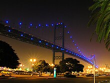


+++++++++++++++++++++++++++++++++++++++++++++++++++++++++++++++++++++++++
e- SMART CONTROLLING LED
+++++++++++++++++++++++++++++++++++++++++++++++++++++++++++++++++++++++++
Thanks for sharing this informative information about RGB LED bulb lights with IR remote control+memory mode with us. It's very helpful. Keep it up!
BalasHapus