Sistem Differensial/Gardan


Cara kerja gardan
Fungsi utama gardan adalah membedakan putaran roda kiri dan kanan pada saat mobil sedang membelok.Hal itu dimaksudkan agar mobil dapat membelok dengan baik tanpa membuat kedua ban menjadi slip atau tergelincir. Untuk mempelajari cara kerja gardan berikut ini , sebaiknya Anda baca terlebih dahulu postingan saya tentang mengenal gardan . Adapun cara kerja gardan adalah sebagai berikut :
Pada saat mobil berjalan lurus :
Pada saat mobil berjalan lurus keadaan kedua ban roda kiri dan kanan sama - sama dalam kecepatan putaran yang sama.Dan juga beban yang ditanggung roda kiri dan roda kanan adalah sama. Sehingga urutan perpindahan putaran dari as kopel akan diteruskan untuk memutar drive pinion . Drive pinion akan memutar ring gear , dan ring gear bersama - sama dengan differential case akan berputar. Dengan berputarnya differential case , maka pinion gear akan terbawa berputar bersama dengan differential case karena antara differential case dan pinion gear dihubungkan dengan pinion shaft. Karena beban antara roda kiri dan roda kanan adalah sama saat jalan lurus , maka pinion gear akan membawa side gear kanan dan side gear kiri untuk berputar dalam satu kesatuan. Jadi dalam keadaan jalan lurus sebenarnya pinion gear tidak berputar , pinion gear hanaya membawa side gear untuk berputar bersama - sama dengan differential case dalam kecepatan putaran yang sama. Bila differential case berputar satu kali , maka side gear juga berputar satu kali juga , demikian seterusnya dalam keadaan lurus. Putaran side gear ini kemudian akan diteruskan untuk menggerakkan as roda dan kemudian menggerakkan roda.
Pada saat kendaraan membelok :
Pada saat mobil sedang membelok beban yang ditanggung pada roda bagian dalam adalah lebih besar daripada beban yang ditanggung roda bagian luar . Misalkan sebuah mobil sedang belok ke kiri, maka beban pada roda kiri akan lebih besar daripada beban roda kanan. Dengan demikian urutan perpindahan tenaganya adalah sebagai berikut ; P:utaran dari as kopel akan diteruskan untuk memutar drive pinion . Drive pinion akan memutar ring gear . Dengan berputarnya ring gear maka differential case akan terbawa juga untuk berputar. Karena beban roda kiri lebih besar dari roda kanan saat belok ke kiri , maka side gear sebelah kiri akan memberi perlawanan terhadap pinion gear untuk tidak berputar . Gaya perlawanan dari side gear kiri ini akan membuat pinion gear menjadi berputar mengitari side gear kiri. Dengan berputarnya pininon gear , maka side gear kanan akan diputar oleh pinion gear. Sehingga side gear kanan akan berputar lebih cepat dari side gear kiri. Gerakan side gear ini akan diteruskan ke as roda kemudian ke roda. Untuk roda kanan akan berputar lebih cepat daripada roda kiri karena side gear kanan berputar lebih cepat.
Penggerak Sudut
1. Bagian – bagian poros penggerak aksel
1. Rumah Penggerak Aksel
2. Gigi Pinion
3. Gigi Korona
4. Gigi Kerucut Samping/Matahari
5. Rumah Differensial
6. Poros Gigi Kerucut Antara
7. Gigi Kerucut Antara/Planet
8. Mounting Rumah Penggerak aksel
9. Tutup Debu
10. Poros Aksel
11. Penghubung Bola/Penghubung CV
12. Bantalan Rumah Diferensial
13. Bantalan Poros Pinion
14. Sil Oli
2. Penggunaan :
Kendaraan dengan motor memanjang, untuk meneruskan putaran ke roda-roda diperlukan penggerak sudut. Karena arah putaran motor berbeda dengan arah putaran roda – roda
3. Fungsi : • Merubah arah putaran dari arah putaran mesin ke kanan ( a ) menjadi arah putaran maju ( b ) ke roda – roda
4. Jenis Penggerak Sudut
Pada saat sekarang penggerak aksel hanya menggunakan penggerak sudut roda korona. Tetapi pada sistem lama, misalnya merek PEUGEOT menggunakan penggerak roda cacing.
Perbandingan gigi pada : • Sedan station antara 3,5 : 1 s/d 4,5 : 1
• Truk antara 5 : 1 s/d 12 : 1
Jenis biasa :
Sumbu poros pinion segaris dengan aksis roda korona Konstruksi ini hanya digunakan pada truk
Kerugian :
• Suara tidak halus
• Gaya pada gigi besar ( Konstruksi Berat )
Jenis biasa :
Sumbu poros pinion segaris dengan aksis roda korona Konstruksi ini hanya digunakan pada truk
Kerugian :
• Suara tidak halus
• Gaya pada gigi besar ( Konstruksi Berat )
Jenis Hypoid
Sumbu poros pinion tidak segaris dengan aksis roda korona
Konstruksi ini : Digunakan pada sedan, station dan truk
Keuntungan :
• Suara halus
• Permukaan gigi yang memindahkan gaya lebih besar
• Poros penggerak ( Gardan ) lebih rendah
Kerugian :
• Perlu oli khusus GL 4 atau GL 5
• Gesekan antara gigi lebih besar
5. Bentuk Gigi
Dari bentuk giginya, roda korona ada 2 macam
• Klingenberg
• Gleason

Klingenberg
• Tebal puncak gigi bagian dalam dan bagian luar sama (A=B)
• Disebut gigi spiral karena bentuk gigi sebagian dari busur spiral
• Kebanyakan digunakan pada mobil Eropa dan Jepang

Gleason
• Tebal puncak gigi bagian dalam dan bagian luar tidak sama (a?b)
• Disebut gigi lingkar karena bentuk – bentuk gigi sebagian dari busur lingkaran
• Kebanyakan digunakan pada mobil Amerika
6. Penyetelan Penggerak Aksel
1. Tinggi pinion
Untuk mendapatkan posisi gigi pinion yang tepat terhadap gigi roda korona
2. Pre – load pinion
Agar keausan bantalan tidak menyebabkan kebebasan bantalan
3. Celah bebas gigi roda korona ( Back Lash )
Roda korona dapat berputar dengan baik/halus dan tidak menimbulkan suara persentuhan gigi atau suara dengung
4. Pre – load bantalan rumah diferensial ( Keseluruhan )
Agar keausan bantalan tidak menimbulkan kebebasan bantalan / gerak aksial roda korona
5. Memeriksa Persinggungan gigi
Untuk menempatkan posisi permukaan kontak gigi pinion dan roda korona benar ( di tengah – tengah ) sehinggga suara halus dan keausan merata
7. Bentuk Rumah Aksel ( Penggerak Aksel )
Dari bentuk rumah penggerak aksel dapat dibedakan tiga macam :
• Aksel Banjo
• Aksel Spicer
• Aksel Terompet
7.1. Aksel Banjo
Rumah bantalan lebih kuat menahan gaya ke samping / aksial roda korona kurang kuat, biasa digunakan pada kendaraan sedan, Station dan Jep
7.2. Aksel Spicer
Rumah bantalan lebih kuat menahan gaya ke samping / aksial roda korona jenis ini sering digunakan pada jeep dan truk
7.4. Aksel Terompet
Rumah bantalan merupakan satu kesatuan yang kokoh dengan rumah aksel, jenis ini paling kuat menahan gaya ke samping / aksial roda korona biasanya digunakan pada jenis kendaraaan berat
Jarang lagi digunakan pada kendaraan, karena :
• Konstruksi rumit
• Penyetelan sulit
• Harga mahal
Jenis Tapak Ban Mobil


Tapak ban searah ini sangat mudah dikenali yakni pada corak/ kembang bagian tengah seperti membentuk huruf v, tapak ban tipe searah ini memiliki kemampuan membuang air yang cukup bagus karena bisa dibuang ke dua arah (sisi luar dan dalam). Ban ini hanya optimal digunakan searah jadi tipe unidirectional jarang digunakan untuk ban offroad. Huruf v seperti anak panah menunjukkan arah maju (putaran kedepan) jadi hati-hati saat memasang ban tipe searah ini karena kesalahan dalan rotasi bisa sangat jelek performanya, biasanya pada dinding ban juga ada tanda panah yang menunjukkan arah rotasi ban.
Ban tipe ini biasanya tersedia untuk tipe di atas 15 inch, nyaman untuk jalan aspal untuk kecepatan dan performa yang tinggi
Tapak Ban Eco
Ban eco dikembangkan oleh produsen ban untuk menghasilkan ban yang ringan dan tidak terlalu mencengkeram pada aspal, ban eco memiliki alur yang sederhana dengan lebar tapak ban yang relatif kecil untuk meminimalkan hambatan akibat gesekan dengan aspal. Ban eco ini sangat baik untuk mobil hemat BBM karena menunjang performa penghematan konsumsi BBM, kurang cocok dipakai pada mobil-mobil SUV karena daya cengkeram ke permukaan jalan kecil (mudah slip)
Ban Alur Lebar
Ban yang menggunakan alur lebar ini biasanya memiliki ketebalan tapak yang tinggi, ban offroad banyak memakai tipe ini (beralur lebar), kelebihan ban dengan alur lebar adalah sangat mumpuni dalam membuang air yang meskipun hujan lebat ban ini mampu membuang air dengan sempurna dan masih mencengkeram aspal dengan baik. Cocok untuk medan-medan ekstrim seperti jalan licin, berair, berpasir dan lain sebagainya.

Ban Slick


Differential (mechanical device)

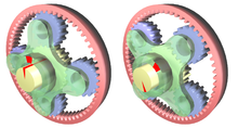
A spur gear differential constructed by engaging the planet gears of two co-axial epicyclic gear trains. The casing is the carrier for this planetary gear train. A differential is a particular type of simple planetary gear train that has the property that the angular velocity of its carrier is the average of the angular velocities of its sun and annular gears. This is accomplished by packaging the gear train so it has a fixed carrier train ratio R = -1, which means the gears corresponding to the sun and annular gears are the same size. This can be done by engaging the planet gears of two identical and coaxial epicyclic gear trains to form a spur gear differential. Another approach is to use bevel gears for the sun and annular gears and a bevel gear as the planet, which is known as a bevel gear differential.
Overview

Automotive differential: The drive gear 2 is mounted on the carrier 5
which supports the planetary bevel gears 4 which engage the driven bevel
gears 3 attached to the axles 1.

ZF Differential. The drive shaft enters from the front and the driven axles run left and right.

Car differential of a Škoda 422
When used in this way, a differential couples the input shaft (or prop shaft) to the pinion, which in turn runs on the crown wheel of the differential. This also works as reduction gearing to give the ratio. On rear wheel drive vehicles the differential may connect to half-shafts inside an axle casing or drive shafts that connect to the rear driving wheels. Front wheel drive vehicles tend to have the pinion on the end of the main-shaft of the gearbox and the differential is enclosed in the same casing as the gearbox. They have individual drive-shafts to each wheel. Older 4x4 vehicles and tractors usually have a solid front axle, the modern way can be a separate differential and drive shaft arrangement for the front.
A differential consists of one input, the drive shaft, and two outputs which are the two drive wheels, however the rotation of the drive wheels are coupled by their connection to the roadway. Under normal conditions, with small tyre slip, the ratio of the speeds of the two driving wheels is defined by the ratio of the radii of the paths around which the two wheels are rolling, which in turn is determined by the track-width of the vehicle (the distance between the driving wheels) and the radius of the turn.
Non-automotive uses of differentials include performing analog arithmetic. Two of the differential's three shafts are made to rotate through angles that represent (are proportional to) two numbers, and the angle of the third shaft's rotation represents the sum or difference of the two input numbers. The earliest known use of a differential gear is in the Antikythera Mechanism, circa 80 BCE, which used a differential gear to control a small sphere representing the moon from the difference between the sun and moon position pointers. The ball was painted black and white in hemispheres, and graphically showed the phase of the moon at a particular point in time.[1] See also the Chinese South-pointing chariot. An equation clock that used a differential for addition was made in 1720. In the 20th Century, large assemblies of many differentials were used as analog computers, calculating, for example, the direction in which a gun should be aimed. However, the development of electronic digital computers has made these uses of differentials obsolete. Military uses may still exist. See Electromagnetic pulse. Practically all the differentials that are now made are used in automobiles and similar vehicles.
Epicyclic gearing is used here to apportion torque asymmetrically. The input shaft is the green hollow one, the yellow is the low torque output, and the pink is the high torque output. The force applied in the yellow and the pink gears is the same, but since the arm of the pink one is 2× to 3× as big, the torque will be 2× to 3× as high.
Epicyclic differential

Epicyclic gearing
is used here to apportion torque asymmetrically. The input shaft is the
green hollow one, the yellow is the low torque output, and the pink is
the high torque output. The force applied in the yellow and the pink
gears is the same, but since the arm of the pink one is 2× to 3× as big,
the torque will be 2× to 3× as high.
Epicyclic gears are also called planetary gears because the axes of the planet gears revolve around the common axis of the sun and ring gears that they mesh with and roll between. In the image, the yellow shaft carries the sun gear which is almost hidden. The blue gears are called planet gears and the pink gear is the ring gear or annulus.
Ring gears are also used in starter motors.
Spur-gear differential
This is another type of differential that was used in some early automobiles, more recently the Oldsmobile Toronado, as well as other non-automotive applications. It consists of spur gears only.A spur-gear differential has two equal-sized spur gears, one for each half-shaft, with a space between them. Instead of the Bevel gear, also known as a miter gear, assembly (the "spider") at the centre of the differential, there is a rotating carrier on the same axis as the two shafts. Torque from a prime mover or transmission, such as the drive shaft of a car, rotates this carrier.
Mounted in this carrier are one or more pairs of identical pinions, generally longer than their diameters, and typically smaller than the spur gears on the individual half-shafts. Each pinion pair rotates freely on pins supported by the carrier. Furthermore, the pinion pairs are displaced axially, such that they mesh only for the part of their length between the two spur gears, and rotate in opposite directions. The remaining length of a given pinion meshes with the nearer spur gear on its axle. Therefore, each pinion couples that spur gear to the other pinion, and in turn, the other spur gear, so that when the drive shaft rotates the carrier, its relationship to the gears for the individual wheel axles is the same as that in a bevel-gear differential.
A spur gear differential is constructed from two identical coaxial epicyclic gear trains assembled with a single carrier such that their planet gears are engaged. This forms a planetary gear train with a fixed carrier train ratio R = -1.
In this case, the fundamental formula for the planetary gear train yields,
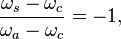
In discussing the spur gear differential, the use of the term annular gear is a convenient way to distinguish the sun gears of the two epicyclic gear trains. The second sun gear serves the same purpose as the annular gear of a simple planetary gear train, but clearly does not have the internal gear mate that is typical of an annular gear.
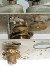 Planetary differential used to drive a chart recorder
circa 1961. The motors drive the sun and annular gears, while the
output is taken from the planet gear carrier. This gives 3 different
speeds depending on which motors are on.
Planetary differential used to drive a chart recorder
circa 1961. The motors drive the sun and annular gears, while the
output is taken from the planet gear carrier. This gives 3 different
speeds depending on which motors are on.Non-automotive applications

Differential used to control the take-up reel of a paper tape reader made by Tally circa 1962. The bevel gears spin freely on their shafts, unless a brake shoe stops the left gear. This causes the planet gear to drive the output shaft at half the speed of the driven gear on the right.

Planetary differential used to drive a chart recorder
circa 1961. The motors drive the sun and annular gears, while the
output is taken from the planet gear carrier. This gives 3 different
speeds depending on which motors are on.
Chinese south-pointing chariots may also have been very early applications of differentials. The chariot had a pointer which constantly pointed to the south, no matter how the chariot turned as it travelled. It could therefore be used as a type of compass. It is widely thought that a differential mechanism responded to any difference between the speeds of rotation of the two wheels of the chariot, and turned the pointer appropriately. However, the mechanism was not precise enough, and, after a few miles of travel, the dial could have very well been pointing in the complete opposite direction.
The earliest definitely verified use of a differential was in a clock made by Joseph Williamson in 1720. It employed a differential to add the Equation of Time to local mean time, as determined by the clock mechanism, to produce solar time, which would have been the same as the reading of a sundial. During the 18th Century, sundials were considered to show the "correct" time, so an ordinary clock would frequently have to be readjusted, even if it worked perfectly, because of seasonal variations in the Equation of Time. Williamson's and other equation clocks showed sundial time without needing readjustment. Nowadays, we consider clocks to be "correct" and sundials usually incorrect, so many sundials carry instructions about how to use their readings to obtain clock time.
In the first half of the twentieth century, mechanical analog computers, called differential analyzers, were constructed that used differential gear trains to perform addition and subtraction. The U.S. Navy Mk.1 gun fire control computer used about 160 differentials of the bevel-gear type.
A differential gear train can be used to allow a difference between two input axles. Mills often used such gears to apply torque in the required axis. Differentials are also used in this way in watchmaking to link two separate regulating systems with the aim of averaging out errors. Greubel Forsey use a differential to link two double tourbillon systems in their Quadruple Differential Tourbillon.
Functional description

Input torque is applied to the ring gear (blue), which turns the entire
carrier (blue). The carrier is connected to both sun gears (red and
yellow) only through the planet gear (green). Torque is transmitted to
the sun gears through the planet gear. The planet gear revolves around
the axis of the carrier, driving the sun gears. If the resistance at
both wheels is equal, the planet gear revolves without spinning about
its own axis, and both wheels turn at the same rate.

If the left sun gear (red) encounters resistance, the planet gear
(green) spins as well as revolving, allowing the left sun gear to slow
down, with an equal speeding up of the right sun gear (yellow).
Thus, for example, if the car is making a turn to the right, the main crown wheel may make 10 full rotations. During that time, the left wheel will make more rotations because it has further to travel, and the right wheel will make fewer rotations as it has less distance to travel. The sun gears (which drive the axle half-shafts) will rotate in opposite directions relative to the ring gear by, say, 2 full turns each (4 full turns relative to each other), resulting in the left wheel making 12 rotations, and the right wheel making 8 rotations.
The rotation of the crown wheel gear is always the average of the rotations of the side sun gears. This is why, if the driven roadwheels are lifted clear of the ground with the engine off, and the drive shaft is held (say leaving the transmission 'in gear', preventing the ring gear from turning inside the differential), manually rotating one driven roadwheel causes the opposite roadwheel to rotate in the opposite direction by the same amount.
When the vehicle is traveling in a straight line, there will be no differential movement of the planetary system of gears other than the minute movements necessary to compensate for slight differences in wheel diameter, undulations in the road (which make for a longer or shorter wheel path), etc.
Automobiles without differentials
Although most automobiles in the developed world use differentials there are a few that do not. Several different types exist:- Race cars and trucks in certain classes. Drag racing is done in a straight line (and often on a prepared surface), which obviates the need for a differential. A spool is used to make a solid connection between both drive wheels, which is simpler and less likely to break under very heavy acceleration. Racing on dirt or mud tracks also allows the use of spools, because the loose surface gives way while cornering. NASCAR mandates the use of spools in their cars, which does cause axle wind-up, and degrades handling in turns. Other forms of racing without differentials includes tractor pulling, mud bogging and other 4x4 motorsports where differential action is not needed.
- Vehicles with a single driving wheel. Besides motorcycles, which are generally not classified as automobiles, this group includes most three-wheeled cars. These were quite common in Europe in the mid-20th Century, but have now become rare there. They are still common in some areas of the developing world, such as India. Some early four-wheeled cars also had only one driving wheel to avoid the need for a differential. However, this arrangement led to many problems. The system was unbalanced, the driving wheel would easily spin, etc.. Because of these problems, few such vehicles were made.
- Vehicles using two freewheels. A freewheel, as used on a pedal bicycle for example, allows a road wheel to rotate faster than the mechanism that drives it, allowing a cyclist to stop pedalling while going downhill. Some early automobiles had the engine driving two freewheels, one for each driving road wheel. When the vehicle turned, the engine would continue to drive the wheel on the inside of the curve, but the wheel on the outside was permitted to rotate faster by its freewheel. Thus, while turning, the vehicle had only one driving wheel. Driving in reverse is also impossible as is engine braking due to the freewheels.
- Vehicles with continuously variable transmissions, such as the DAF Daffodil. The Daffodil, and other similar vehicles which were made until the 1970s by the Dutch company DAF, had a type of transmission that used an arrangement of belts and pulleys to provide an infinite number of gear ratios. The engine drove two separate transmissions which ran the two driving wheels. When the vehicle turned, the two wheels could rotate at different speeds, making the two transmissions shift to different gear ratios, thus functionally substituting for a differential. The slower moving wheel received more driving torque than the faster one, so the system had limited-slip characteristics. The duplication also provided redundancy. If one belt broke, the vehicle could still be driven.
- Light vehicles with closely spaced rear wheels, such as the Isetta and Opperman Unicar, or very low mass vehicles.
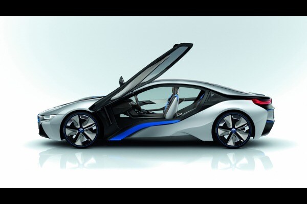
- Vehicles with separate motors for the driving wheels. Electric cars can have a separate motor for each driving wheel, eliminating the need for a differential, but usually with some form of gearing at each motor to get the large wheel torques necessary. A multi-motor electric vehicle such as the Dual Motor Tesla Model S can electronically control the power distribution between the motors on a millisecond scale, in this case acting as a centre differential where open differentials are still employed left-to-right.


Automatic lockers
Automatic lockers lock and unlock automatically with no direct input from the driver. Some automatic locking differential designs ensure that engine power is always transmitted to both wheels, regardless of traction conditions, and will "unlock" only when one wheel is required to spin faster than the other during cornering. These would be more correctly termed "automatic unlocking" differentials, because their at-rest position is locked. They will never allow either wheel to spin slower than the differential carrier or axle as a whole, but will permit a wheel to be over-driven faster than the carrier speed. The most common example of this type would be the famous "Detroit Locker," also known as the "Detroit No-Spin," which replaces the entire differential carrier assembly. Others, sometimes referred to as "lunchbox lockers," employ the stock differential carrier and replace only the internal spider gears and shafts with interlocking plates. Both types of automatic lockers will allow for a degree of differential wheel speed while turning corners in conditions of equal traction, but will otherwise lock both axle shafts together when traction conditions demand it.- Pros: Automatic action, no driver interaction necessary, no stopping for (dis-) engagement necessary, continuous driving even in unforeseen road condition changes
- Cons: Increased tire wear and noticeable impact on driving behavior. During cornering, which half-axle is uncoupled is dependent on torque direction applied by the drivelive. When the torque direction is reversed, the speed of the driveline is suddenly forced to change from the inner to outer axle, accompanied by tire chirping and a large jerk. During cornering, the automatic locker is characterized by heavy understeer which transitions instantly to power oversteer when traction is exceeded.
Some other automatic lockers operate as an open differential until high torque is applied and then they lock up. This style generally uses internal gears systems with very high friction. An example of this is the ZF "sliding pins and cams" available for use in early Volkswagens.
Selectable lockers
Selectable lockers allow the driver to lock and unlock the differential at will from the driver's seat. This can be accomplished many ways.- Compressed air (pneumatics).
- Cable operated mechanism as is employed on the "Ox Locker."
- Electronic solenoids and (electromagnetics)
like Eaton's "ELocker." However, OEMs are beginning to offer electronic
lockers as well. Nissan Corporation's electric locker can be found as
optional equipment on the Frontier (Navara) & Xterra.
- Pros: Allows the differential to perform as an "open" differential for improved driveability, maneuverability, provides full locking capability when it is desirable or needed
- Cons: Mechanically complex with more parts to fail. Some lockers require vehicle to stop for engagement. Needs human interaction and forward-thinking regarding upcoming terrain. Unskilled drivers often put massive stress on driveline components when leaving the differential in locked operation on terrain not requiring a locker.
Spool
A spool is a device that connects the two axles directly to the ring gear. There is no differentiation side to side, so a vehicle equipped with a spool will bark tires in turns and may become unmanageable in wet or snowy weather. Spools are usually reserved for competition vehicles not driven on the street.Mini-spool uses the stock carrier and replaces only the internal components of the differential, similar in installation to the lunchbox locker. A full spool replaces the entire carrier assembly with a single machined piece. A full spool is perhaps the strongest means of locking an axle, but has no ability to differentiate wheel speeds whatsoever, putting high stress on all affected driveline components.
The internal spider gears of an open differential can also be welded together to create a locked axle; this method is not recommended as the welding process seriously compromises the metallurgical composition of the welded components, and can lead to failure of the unit under stress. If it is desirable to have a spooled axle, the better option is to install either a mini-spool or a full spool.
Disadvantages
Because they do not operate as smoothly as standard differentials, automatic locking differentials are often responsible for increased tire wear. Some older automatic locking differentials are known for making a clicking or banging noise when locking and unlocking as the vehicle negotiates turns. This is annoying to many drivers. Also, automatic locking differentials will affect the ability of a vehicle to steer, particularly if a locker is located in the front axle. Aside from tire scuffing while turning any degree on high friction (low slip) surfaces, locked axles provoke understeer and, if used on the front axle, will increase steering forces required to turn the vehicle. Furthermore, automatically locking differentials can cause a loss of control on ice where an open differential would allow one wheel to spin and the other to hold, while not transferring power. An example of this would be a vehicle parked sideways on a slippery grade. When both wheels spin, the vehicle will break traction and slide down the grade.Alternatives
Limited slip differentials are considered a compromise between a standard differential and a locking differential because they operate more smoothly, and they do direct some extra torque to the wheel with the most traction compared to a standard differential, but they are not capable of 100% lockup.Traction control systems are also used in many modern vehicles either in addition or as a replacement of locking differentials. One example is that offered by Volkswagen under the name of electronic differential lock (EDL). This EDL is not in fact a differential lock, but operates at each wheel. Sensors monitor wheel speeds, and if one is rotating more than 100 RPM more than the other (i.e. slipping) the EDL system momentarily brakes it. This transfers more power to the other wheel, but still employs the open differential, which is the same as on cars without the EDL option. Electronic traction control systems may be integrated with anti-lock braking systems, which have a similar action on braking and use some similar components. Such systems are used for example on the most recent Nissan Pathfinder, Land Rover Defender, Land Rover Freelander, the McLaren P1 and the McLaren 650s.
Applications
- Race cars often use locking differentials in order to maintain traction during high speed maneuvers or when accelerating at extreme rates. Additionally, vehicle dynamics are made more predictable when there is a loss of traction, as the driver knows that neither wheel will suddenly sap power if it encounters a low-friction surface.
- Some utility vehicles such as tow trucks, forklifts, tractors, and heavy equipment use locking differentials to maintain traction, especially when driving on soft, muddy, or uneven surfaces. Lockers are common in agricultural equipment and military trucks. On some farm tractors, there is a pedal that can be stepped on with the operator's heel to lock the differential as needed.
- Differential locking can also be used in the sport of drifting as an alternative to a limited slip differential.
- Four-wheel drive vehicles that drive off-road often use a locking differential to keep from getting stuck when driving on loose, muddy, or rocky terrain. Locking differentials are considered essential equipment for serious off-road driving. Many such vehicles have a locking differential on the central differential (between the front and rear axles), rear differential and front differential; or any combination of any of the three. Differential locks are also used on some "non-utility" four-wheel-drive vehicles (such as the Mitsubishi Shogun) to compensate for a relative lack of axle articulation (vertical wheel movement). High amounts of articulation are desirable for off-road driving, to allow the wheels to maintain ground contact over uneven surfaces, but this can lead to excessive body-roll at high speeds on the road, as well as vague steering. Such 4x4s often have suspension systems designed as a compromise between articulation and handling. If articulation is limited, one wheel on an axle may be lifted off the ground by rough terrain, thus losing all traction to all wheels (all power goes to the lifted wheel, which spins freely). A rear locking differential is often supplied to make up for this compromise – if a wheel is lifted off the ground, the locking differential can be brought into play, driving the wheel that remains on the ground.

Tidak ada komentar:
Posting Komentar