Jet engine performance

The thrust, noise and emission elements of the operation of a jet engine are of vital importance in the takeoff phase of operation of the aircraft. The thrust and fuel consumption elements, and their variation with altitude, are of vital importance in the climb and cruise phases of operation of the aircraft.
The behaviour of a jet engine and its effect both on the aircraft and the environment is categorised into different engineering areas or disciplines. For example the emissions come under a group called combustion, the origin of vibrations transmitted to the airframe come under an area called rotor dynamics. So what is performance? When the airframe sees fuel disappearing from its tanks and feels a thrust. The understanding of how a particular fuel flow produces a definite amount of thrust at a particular point in the flight envelope is called jet engine performance. Performance is the subject of a specialised discipline within aero engine design and development teams as is the understanding of noise and emissions by their respective specialists in other groups.
The fundamental performance task for a single shaft turbojet is to match the operation of the compressor, turbine and propelling nozzle. For example, the way the compressor operates is determined by the flow resistances behind it, which occur in the combustor, turbine, tailpipe and propelling nozzle.
Matching may be defined as designing, sizing, and manipulating the operating characteristics of the compressor, turbine and propelling nozzle.
Three fundamental observations are built upon as outlined below to develop the required understanding to match the components efficiently. The flow through the compressor is the same as that through the turbine. The speeds are the same. The power produced by the turbine equals that absorbed by the compressor. In addition, the flow resistance seen by the compressor is determined by the two restrictors downstream, namely the turbine nozzle area and the propelling nozzle exit area.
The above three ties between the compressor and turbine are adjusted and refined to account for the flows and powers not being equal due to, for example, compressor flow and electric and hydraulic power being diverted to the airframe. Thus the performance is understood and defined by using the practical engineering application of thermodynamics and aerodynamics.
This article covers a wide scope of the discipline of jet engine performance.
Design point

TS diagram

Temperature vs. entropy (TS) diagrams (see example RHS) are usually used to illustrate the cycle of gas turbine engines. Entropy represents the degree of disorder of the molecules in the fluid. It tends to increase as energy is converted between different forms, i.e. chemical and mechanical.
The TS diagram shown on the RHS is for a single spool turbojet, where a single drive shaft connects the turbine unit with the compressor unit.
Apart from stations 0 and 8s, stagnation pressure and stagnation temperature are used. Station 0 is ambient. Stagnation quantities are frequently used in gas turbine cycle studies, because no knowledge of the flow velocity is required.
The processes depicted are:
- Freestream (stations 0 to 1)
- In the example, the aircraft is stationary, so stations 0 and 1 are coincident. Station 1 is not depicted on the diagram.
- Intake (stations 1 to 2)
- In the example, a 100% intake pressure recovery is assumed, so stations 1 and 2 are coincident.
- Compression (stations 2 to 3)
- The ideal process would appear vertical on a TS diagram. In the real process there is friction, turbulence and, possibly, shock losses, making the exit temperature, for a given pressure ratio, higher than ideal. The shallower the positive slope on the TS diagram, the less efficient the compression process.
- Combustion (stations 3 to 4)
- Heat (usually by burning fuel) is added, raising the temperature of the fluid. There is an associated pressure loss, some of which is unavoidable
- Turbine (stations 4 to 5)
- The temperature rise in the compressor dictates that there will be an associated temperature drop across the turbine. Ideally the process would be vertical on a TS diagram. However, in the real process, friction and turbulence cause the pressure drop to be greater than ideal. The shallower the negative slope on the TS diagram, the less efficient the expansion process.
- Jetpipe (stations 5 to 8)
- In the example the jetpipe is very short, so there is no pressure loss. Consequently, stations 5 and 8 are coincident on the TS diagram.
- Nozzle (stations 8 to 8s)
- These two stations are both at the throat of the (convergent) nozzle. Station 8s represents static conditions. Not shown on the example TS diagram is the expansion process, external to the nozzle, down to ambient pressure.
The above calculations assume that the fuel flow added in the combustor completely offsets the bleed air extracted at compressor delivery to cool the turbine system. This is pessimistic, since the bleed air is assumed to be dumped directly overboard (thereby bypassing the propulsion nozzle) and unable to contribute to the thrust of the engine.
In a more sophisticated performance model, the cooling air for the first row of (static) turbine nozzle guide vanes (immediately downstream of the combustor) can be safely disregarded, since for a given (HP) rotor inlet temperature it has no effect upon either the combustor fuel flow or the net thrust of the engine. However, the turbine rotor cooling air must be included in such a model. The rotor cooling bleed air is extracted from compressor delivery and passes along narrow passage ways before being injected into the base of the rotating blades. The bleed air negotiates a complex set of passageways within the aerofoil extracting heat before being dumped into the gas stream adjacent to the blade surface. In a sophisticated model, the turbine rotor cooling air is assumed to quench the main gas stream emerging from turbine, reducing its temperature, but also increasing its mass flow:
i.e.


The bleed air cooling the turbine discs is treated in a similar manner. The usual assumption is that the low energy disc cooling air cannot contribute to the engine cycle until it has passed through one row of blades or vanes.
Naturally any bleed air returned to the cycle (or dumped overboard) must also be deducted from the main air flow at the point it is bled from the compressor. If the some of the cooling air is bled from part way along the compressor (i.e. interstage), the power absorbed by the unit must be adjusted accordingly.
Cycle improvements
Increasing the design overall pressure ratio of the compression system raises the combustor entry temperature. Therefore, at a fixed fuel flow and airflow, there is an increase in turbine inlet temperature. Although the higher temperature rise across the compression system implies a larger temperature drop over the turbine system, the nozzle temperature is unaffected, because the same amount of heat is being added to the total system. There is, however, a rise in nozzle pressure, because turbine expansion ratio increases more slowly than the overall pressure ratio (which is inferred by the divergence of the constant pressure lines on the TS diagram). Consequently, net thrust increases, implying a specific fuel consumption (fuel flow/net thrust) decrease.So turbojets can be made more fuel efficient by raising overall pressure ratio and turbine inlet temperature in unison.
However, better turbine materials and/or improved vane/blade cooling are required to cope with increases in both turbine inlet temperature and compressor delivery temperature. Increasing the latter may also require better compressor materials. Also, higher combustion temperatures can potentially lead to greater emissions of nitrogen oxides, associated with acid rain.
Adding a rear stage to the compressor, to raise overall pressure ratio, does not require a shaft speed increase, but it reduces core size and requires a smaller flow size turbine, which is expensive to change.
Alternatively, adding a zero (i.e. front) stage to the compressor, to increase overall pressure ratio, will require an increase in shaft speed (to maintain the same blade tip Mach number on each of the original compressor stages, since the delivery temperature of each of these stages will be higher than datum). The increase in shaft speed raises the centrifugal stresses in both the turbine blade and disc. This together with increases in the hot gas and cooling air(from the compressor) temperatures implies a decrease in component lives and/or an upgrade in component materials. Adding a zero stage also induces more airflow into the engine, thereby increasing net thrust.
If the increase overall pressure ratio is obtained aerodynamically (i.e. without adding stage/s), an increase in shaft speed will still probably be required, which has an impact on blade/disc stresses and component lives/material.
Other gas turbine engine types
Design point calculations for other gas turbine engine types are similar in format to that given above for a single spool turbojet.The design point calculation for a two spool turbojet, has two compression calculations; one for the Low Pressure (LP) Compressor, the other for the High Pressure (HP) Compressor. There is also two turbine calculations; one for the HP Turbine, the other for the LP Turbine.
In a two spool unmixed turbofan, the LP Compressor calculation is usually replaced by Fan Inner (i.e. hub) and Fan Outer (i.e. tip) compression calculations. The power absorbed by these two "components" is taken as the load on the LP turbine. After the Fan Outer compression calculation, there is a Bypass Duct pressure loss/Bypass Nozzle expansion calculation. Net thrust is obtained by deducting the intake ram drag from the sum of the Core Nozzle and Bypass Nozzle gross thrusts.
A two spool mixed turbofan design point calculation is very similar to that for an unmixed engine, except the Bypass Nozzle calculation is replaced by a Mixer calculation, where the static pressures of the core and bypass streams at the mixing plane are usually assumed to be equal.

Transient model
So far we have examined steady state performance modelling.A crude transient performance model can be developed by relatively minor adjustments to the off-design calculation. A transient acceleration (or deceleration) is assumed to cover a large number of small time steps of, say, 0.01 s duration. During each time step, the shaft speed is assumed to be momentarily constant. So in the modified off-design iteration,
 is frozen and a new variable, the excess turbine power
  , allowed to float instead. After the iteration has converged, the excess power is used to estimate the change in shaft speed:
Now:
Acceleration torque = spool inertia * shaft angular acceleration
 =
= 

 /
/
Rearranging:
= ( /( )) But:
= 
 /
/
So:
= ( / ( )) Or approximating:
 = (
= ( / ( ))
This change in shaft speed is used to calculate a new (frozen) shaft speed for the next time interval:
 =
=  +
+ The whole process, described above, is then repeated for the new time:
 =
=  +
+ The starting point for the transient is some steady state point (e.g. Ground Idle, Sea Level Static, ISA). A ramp of fuel flow versus time is, for instance, fed into the model to simulate, say, a slam acceleration (or deceleration). The transient calculation is first undertaken for time zero, with the steady state fuel flow as the engine match, which should result in zero excess turbine power. By definition, the first transient calculation should reproduce the datum steady state point. The fuel flow for
 is calculated from the fuel flow ramp and is used as the revised engine
match in the next transient iterative calculation. This process is
repeated until the transient simulation is completed.
is calculated from the fuel flow ramp and is used as the revised engine
match in the next transient iterative calculation. This process is
repeated until the transient simulation is completed.It should be noted that the transient model described above is pretty crude, since it only takes into account inertia effects, other effects being ignored. For instance, under transient conditions the entry mass flow to a volume (e.g. jetpipe) needn't be the same as the exit mass flow; i.e. the volume could be acting as an accumulator, storing or discharging gas. Similarly part of the engine structure (e.g. nozzle wall) could be extracting or adding heat to the gas flow, which would affect that component's discharge temperature.
During a Slam Acceleration on a single spool turbojet, the working line of the compressor tends to deviate from the steady state working line and adopt a curved path, initially going towards surge, but slowly returning to the steady state line, as the fuel flow reaches a new higher steady state value. During the initial overfuelling, the inertia of the spool tends to prevent the shaft speed from accelerating rapidly. Naturally, the extra fuel flow increases the turbine rotor entry temperature,
 . Since the turbine operates between two choked planes (i.e. the
turbine and nozzle throats), the turbine pressure ratio and the
corresponding temperature drop/entry temperature,
. Since the turbine operates between two choked planes (i.e. the
turbine and nozzle throats), the turbine pressure ratio and the
corresponding temperature drop/entry temperature,  , remain approximately constant. Since
increases, so must the temperature drop across the turbine and the
turbine power output. This extra turbine power, increases the
temperature rise across the compressor and, therefore, the compressor
pressure ratio. Since the corrected speed of the compressor has hardly
changed, the working point tends to move upwards, along a line of
roughly constant corrected speed. As time progresses the shaft begins to
accelerate and the effect just described diminishes.
, remain approximately constant. Since
increases, so must the temperature drop across the turbine and the
turbine power output. This extra turbine power, increases the
temperature rise across the compressor and, therefore, the compressor
pressure ratio. Since the corrected speed of the compressor has hardly
changed, the working point tends to move upwards, along a line of
roughly constant corrected speed. As time progresses the shaft begins to
accelerate and the effect just described diminishes.During a Slam Deceleration, the opposite trend is observed; the transient compressor working line goes below the steady state line.
The transient behaviour of the high pressure (HP) compressor of a turbofan is similar to that described above for a single spool turbojet.
Civil

Military


Scramjet THE FUTURE PROGRAMMING
A scramjet (supersonic combusting ramjet) is a variant of a ramjet airbreathing jet engine in which combustion takes place in supersonic airflow. As in ramjets, a scramjet relies on high vehicle speed to forcefully compress the incoming air before combustion (hence ramjet), but a ramjet decelerates the air to subsonic velocities before combustion, while airflow in a scramjet is supersonic throughout the entire engine. This allows the scramjet to operate efficiently at extremely high speeds.

Before year 2000
During World War II, a tremendous amount of time and effort were put into researching high-speed jet- and rocket-powered aircraft, predominantly by the Germans.[citation needed] After the war, the US and UK took in several German scientists and military technologies through Operation Paperclip to begin putting more emphasis on their own weapons development, including jet engines. The Bell X-1 attained supersonic flight in 1947 and, by the early 1960s, rapid progress towards faster aircraft suggested that operational aircraft would be flying at "hypersonic" speeds within a few years. Except for specialized rocket research vehicles like the North American X-15 and other rocket-powered spacecraft, aircraft top speeds have remained level, generally in the range of Mach 1 to Mach 3.In the 1950s and 1960s a variety of experimental scramjet engines were built and ground tested in the US and the UK. In 1964, Dr. Frederick S. Billig and Dr. Gordon L. Dugger submitted a patent application for a supersonic combustion ramjet based on Billig’s Ph.D. thesis. This patent was issued in 1981 following the removal of an order of secrecy.
In 1981 tests were made in Australia under the guidance of Professor Ray Stalker in the T3 ground test facility at ANU .
The first successful flight test of a Scramjet was performed by Russia in 1991. It was an axisymmetric hydrogen-fueled dual-mode scramjet developed by Central Institute of Aviation Motors (CIAM), Moscow in the late 1970s. The scramjet flight was flown captive-carry atop the SA-5 surface-to-air missile that included an experiment flight support unit known as the "Hypersonic Flying Laboratory" (HFL), "Kholod".
Then from 1992 to 1998 an additional 6 flight tests of the axisymmetric high-speed scramjet-demonstrator were conducted by CIAM together with France and then with NASA, USA. Maximum flight velocity greater than Mach 6.4 was achieved and Scramjet operation during 77 seconds was demonstrated. These flight test series also provided insight into autonomous hypersonic flight controls.

Progress in the 2000s

Artist's conception of the NASA X-43 with scramjet attached to the underside
The HyShot project demonstrated scramjet combustion on July 30, 2002. The scramjet engine worked effectively and demonstrated supersonic combustion in action. However, the engine was not designed to provide thrust to propel a craft. It was designed more or less as a technology demonstrator.
A joint British and Australian team from UK defense company QinetiQ and the University of Queensland were the first group to demonstrate a scramjet working in an atmospheric test.
US efforts are probably the best funded, and the Hyper-X team claimed the first flight of a thrust-producing scramjet-powered vehicle with full aerodynamic maneuvering surfaces in 2004 with the X-43A.
On Friday, June 15, 2007, the US Defense Advanced Research Project Agency (DARPA), in cooperation with the Australian Defence Science and Technology Organisation (DSTO), announced a successful scramjet flight at Mach 10 using rocket engines to boost the test vehicle to hypersonic speeds.
A series of scramjet ground tests was completed at NASA Langley Arc-Heated Scramjet Test Facility (AHSTF) at simulated Mach 8 flight conditions. These experiments were used to support HIFiRE flight 2.
On May 22, 2009, Woomera hosted the first successful test flight of a hypersonic aircraft in HIFiRE. The launch was one of 10 planned test flights. The series of up to 10 planned hypersonic flight experiments is part of a joint research program between the Defence Science and Technology Organisation and the US Air Force, designated as the Hypersonic International Flight Research Experimentation (HIFiRE). HIFiRE is investigating hypersonics technology (the study of flight exceeding five times the speed of sound) and its application to advanced scramjet-powered space launch vehicles — the objective is to support the new Boeing X-51 scramjet demonstrator while also building a strong base of flight test data for quick-reaction space launch development and hypersonic "quick-strike" weapons.
Progress in the 2010s
On 22 and 23 March 2010, Australian and American defense scientists successfully tested a (HIFiRE) hypersonic rocket. It reached an atmospheric velocity of "more than 5,000 kilometres per hour" after taking off from the Woomera Test Range in outback South Australia.On May 27, 2010, NASA and the United States Air Force successfully flew the X-51A Waverider for approximately 200 seconds at Mach 5, setting a new world record hypersonic airspeed. The Waverider flew autonomously before losing acceleration for an unknown reason and destroying itself as planned. The test was declared a success. The X-51A was carried aboard a B-52, accelerated to Mach 4.5 via a solid rocket booster, and then ignited the Pratt & Whitney Rocketdyne scramjet engine to reach Mach 5 at 70,000 feet. However, a second flight on 13 June 2011 was ended prematurely when the engine lit briefly on ethylene but failed to transition to its primary JP-7 fuel, failing to reach full power.
On 16 November 2010, Australian scientists successfully demonstrated that the high-speed flow in a naturally non-burning scramjet engine can be ignited using a pulsed laser source.
A further X-51A Waverider test failed on August 15, 2012. The attempt to fly the Scramjet, carried by a B-52 for a prolonged period at Mach 6 was cut short when, only 15 seconds into the unmanned flight, the X-51A craft lost control and broke apart, falling into the Pacific Ocean north-west of Los Angeles. The cause of the failure was blamed on a faulty control fin.
In May 2013 an unmanned X-51A WaveRider reached 4828 km/h (Mach 5.1) during a three-minute flight under scramjet power. The WaveRider was dropped at 50,000 feet from a B-52 bomber, and then accelerated to Mach 4.8 by a solid rocket booster which then separated before the WaveRider's scramjet engine came into effect.
Design principles
Scramjet engines are a type of jet engine, and rely on the combustion of fuel and an oxidizer to produce thrust. Similar to conventional jet engines, scramjet-powered aircraft carry the fuel on board, and obtain the oxidizer by the ingestion of atmospheric oxygen (as compared to rockets, which carry both fuel and an oxidizing agent). This requirement limits scramjets to suborbital atmospheric propulsion, where the oxygen content of the air is sufficient to maintain combustion.The scramjet is composed of three basic components: a converging inlet, where incoming air is compressed; a combustor, where gaseous fuel is burned with atmospheric oxygen to produce heat; and a diverging nozzle, where the heated air is accelerated to produce thrust. Unlike a typical jet engine, such as a turbojet or turbofan engine, a scramjet does not use rotating, fan-like components to compress the air; rather, the achievable speed of the aircraft moving through the atmosphere causes the air to compress within the inlet. As such, no moving parts are needed in a scramjet. In comparison, typical turbojet engines require inlet fans, multiple stages of rotating compressor fans, and multiple rotating turbine stages, all of which add weight, complexity, and a greater number of failure points to the engine.
Due to the nature of their design, scramjet operation is limited to near-hypersonic velocities. As they lack mechanical compressors, scramjets require the high kinetic energy of a hypersonic flow to compress the incoming air to operational conditions. Thus, a scramjet-powered vehicle must be accelerated to the required velocity (usually about Mach 4) by some other means of propulsion, such as turbojet, railgun, or rocket engines. In the flight of the experimental scramjet-powered Boeing X-51A, the test craft was lifted to flight altitude by a Boeing B-52 Stratofortress before being released and accelerated by a detachable rocket to near Mach 4.5. In May 2013, another flight achieved an increased speed of Mach 5.1.
While scramjets are conceptually simple, actual implementation is limited by extreme technical challenges. Hypersonic flight within the atmosphere generates immense drag, and temperatures found on the aircraft and within the engine can be much greater than that of the surrounding air. Maintaining combustion in the supersonic flow presents additional challenges, as the fuel must be injected, mixed, ignited, and burned within milliseconds. While scramjet technology has been under development since the 1950s, only very recently have scramjets successfully achieved powered flight.

The compression, combustion, and expansion regions of: (a) turbojet, (b) ramjet, and (c) scramjet engines.
Basic principles
Scramjets are designed to operate in the hypersonic flight regime, beyond the reach of turbojet engines, and, along with ramjets, fill the gap between the high efficiency of turbojets and the high speed of rocket engines. Turbomachinery-based engines, while highly efficient at subsonic speeds, become increasingly inefficient at transonic speeds, as the compressor fans found in turbojet engines require subsonic speeds to operate. While the flow from transonic to low supersonic speeds can be decelerated to these conditions, doing so at supersonic speeds results in a tremendous increase in temperature and a loss in the total pressure of the flow. Around Mach 3–4, turbomachinery is no longer useful, and ram-style compression becomes the preferred method.Ramjets utilize high-speed characteristics of air to literally 'ram' air through an inlet diffuser into the combustor. At transonic and supersonic flight speeds, the air upstream of the inlet is not able to move out of the way quickly enough, and is compressed within the diffuser before being diffused into the combustor. Combustion in a ramjet takes place at subsonic velocities, similar to turbojets, but the combustion products are then accelerated through a convergent-divergent nozzle to supersonic speeds. As they have no mechanical means of compression, ramjets cannot start from a standstill, and generally do not achieve sufficient compression until supersonic flight. The lack of intricate turbomachinery allows ramjets to deal with the temperature rise associated with decelerating a supersonic flow to subsonic speeds, but this only goes so far: at near-hypersonic velocities, the temperature rise and inefficiencies discourage decelerating the flow to the magnitude found in ramjet engines.
Scramjet engines operate on the same principles as ramjets, but do not decelerate the flow to subsonic velocities. Rather, a scramjet combustor is supersonic: the inlet decelerates the flow to a lower Mach number for combustion, after which it is accelerated to an even higher Mach number through the nozzle. By limiting the amount of deceleration, temperatures within the engine are kept at a tolerable level, from both a material and combustive standpoint. Even so, current scramjet technology requires the use of high-energy fuels and active cooling schemes to maintain sustained operation, often using hydrogen and regenerative cooling techniques.
This places stringent requirements on the pressure and temperature of the flow, and requires that the fuel injection and mixing be extremely efficient. Usable dynamic pressures lie in the range 20 to 200 kilopascals (2.9 to 29.0 psi), where

The performance of a launch system is complex and depends greatly on its weight. Normally craft are designed to maximise range (
 ), orbital radius () or payload mass fraction (
 )
for a given engine and fuel. This results in tradeoffs between the
efficiency of the engine (takeoff fuel weight) and the complexity of the
engine (takeoff dry weight), which can be expressed by the following:
)
for a given engine and fuel. This results in tradeoffs between the
efficiency of the engine (takeoff fuel weight) and the complexity of the
engine (takeoff dry weight), which can be expressed by the following: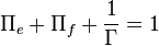
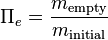 is the empty mass fraction, and represents the weight of the superstructure, tankage and engine.
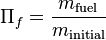 is the fuel mass fraction, and represents the weight of fuel, oxidiser
and any other materials which are consumed during the launch.
is the fuel mass fraction, and represents the weight of fuel, oxidiser
and any other materials which are consumed during the launch. is initial mass ratio, and is the inverse of the payload mass fraction.
This represents how much payload the vehicle can deliver to a
destination.
is initial mass ratio, and is the inverse of the payload mass fraction.
This represents how much payload the vehicle can deliver to a
destination.
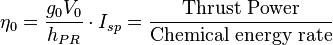
Where:
 is the acceleration due to gravity at ground level
 is the vehicle speed
 is the specific impulse
 is fuel heat of reaction
Applications
An aircraft using this type of jet engine could dramatically reduce the time it takes to travel from one place to another, potentially putting any place on Earth within a 90-minute flight. However, there are questions about whether such a vehicle could carry enough fuel to make useful length trips, and there are heavy FAA regulations regarding aircraft that create sonic booms over United States land.<Scramjet vehicle has been proposed for a single stage to tether vehicle, where a Mach 12 spinning orbital tether would pick up a payload from a vehicle at around 100 km and carry it to orbit.
Need for additional propulsion to reach orbit
Scramjets might be able to accelerate from approximately Mach 5-7 to around somewhere between half of orbital speed and orbital speed (X-30 research suggested that Mach 17 might be the limit compared to an orbital speed of Mach 25, and other studies put the upper speed limit for a pure scramjet engine between Mach 10 and 25, depending on the assumptions made). Generally, another propulsion system (very typically, a rocket is proposed) is expected to be needed for the final acceleration into orbit. Since the delta-V is moderate and the payload fraction of scramjets high, lower performance rockets such as solids, hypergolics, or simple liquid fueled boosters might be acceptable.Theoretical projections place the top speed of a scramjet between Mach 12 (8,400 mph; 14,000 km/h) and Mach 24 (16,000 mph; 25,000 km/h). For comparison, the orbital speed at 200 kilometres (120 mi) low earth orbit is 7.79 kilometres per second (17,400 mph; 28,000 km/h). A scramjet cannot produce efficient thrust unless boosted to high speed, around Mach 5, although depending on the design it could act as a ramjet at low speeds. A horizontal take-off aircraft would need conventional turbofan or rocket engines to take off, sufficiently large to move a heavy craft. Also needed would be fuel for those engines, plus all engine-associated mounting structure and control systems. Turbofan engines are heavy and cannot easily exceed about Mach 2-3, so another propulsion method would be needed to reach scramjet operating speed. That could be ramjets or rockets. Those would also need their own separate fuel supply, structure, and systems. Many proposals instead call for a first stage of droppable solid rocket boosters, which greatly simplifies the design.
Being UK’s independent compressed air house, Cooper Freer provides top quality air compressor products. Our products meet your specific needs and have earned us great reputation in Nottingham, Derby, UK, Milton Keynes, Kettering, Coventry, and Lincoln.
BalasHapus