
the theory of Centrifugal compressors, sometimes termed radial compressors, are a sub-class of dynamic axisymmetric work-absorbing turbomachinery.
The idealized compressive dynamic turbo-machine achieves a pressure rise by adding kinetic energy/velocity to a continuous flow of fluid through the rotor or impeller. This kinetic energy is then converted to an increase in potential energy/static pressure by slowing the flow through a diffuser. The pressure rise in impeller is in most cases almost equal to the rise in the diffuser section.


Theory of operation

Turbomachinery similarities
Centrifugal compressors are similar in many ways to other turbomachinery and are compared and contrasted as follows:| Similarities to axial compressor
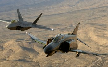
Centrifugal compressors are similar to axial compressors in that they are rotating airfoil based compressors as shown in the adjacent figure.
It should not be surprising that the first part of the centrifugal
impeller looks very similar to an axial compressor. This first part of
the centrifugal impeller is also termed an inducer. Centrifugal compressors differ from axials as they use a greater change in radius from inlet to exit of the rotor/impeller. |

|
| similarities to centrifugal fan
Centrifugal compressors are also similar to centrifugal fans of the style shown in neighboring figure as they both increase the flows energy through increasing radius.
In contrast to centrifugal fans, compressors operate at higher speeds
to generate greater pressure rises. In many cases the engineering
methods used to design a centrifugal fan are the same as those to design
a centrifugal compressor. As a result, they can at times look very
similar. This relationship is less true in comparison to a squirrel-cage fan as shown in figure farthest right. For purposes of generalization and definition, it can be said that centrifugal compressors often have density increases greater than 5 percent. Also, they often experience relative fluid velocities above Mach number 0.3 when the working fluid is air or nitrogen. In contrast, fans or blowers are often considered to have density increases of less than five percent and peak relative fluid velocities below Mach 0.3. |

|
A low speed, low pressure centrifugal compressor or centrifugal fan, with upward discharging cone used to diffuse the air velocity

| Similarities to centrifugal pump
Centrifugal compressors are also similar to centrifugal pumps[1]
of the style shown in the adjacent figures. The key difference between
such compressors and pumps is that the compressor working fluid is a gas
(compressible) and the pump working fluid is liquid (incompressible).
Again, the engineering methods used to design a centrifugal pump are the
same as those to design a centrifugal compressor. Yet, there is one
important difference: the need to deal with cavitation in pumps. |

|
A 3D-solids model of a type of centrifugal pump

| Similarities to radial turbine
Centrifugal compressors also look very similar to their turbomachinery counterpart the Radial_turbine
as shown in the figure. While a compressor transfers energy into a flow
to raise its pressure, a turbine operates in reverse, by extracting
energy from a flow, thus reducing its pressure. In other words, power is input to compressors and output from turbines. |

|
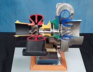
Turbo charger

Π theorem
The three independent dimensions used in this procedure for turbomachinery are:-
 mass (force is an alternative)
-
 length
-
 time
time
| Flow: |  |
 |
ex. = m^3/s |
| Head: |  |
 |
ex. = kg*m/s^2 |
| Speed: |  |
 |
ex. = m/s |
| Power: |  |
 |
ex. = kg*m^2/s^3 |
| Density: |  |
 |
ex. = kg/m^3 |
| Viscosity: |  |
 |
ex. = kg/(m*s) |
| Diameter: |  |
 |
ex. = m |
| Speed of sound: |  |
|
ex. = m/s |
Classic turbomachinery similitude
Completing the task of following the formal procedure results in generating this classic set of five dimensionless parameters for turbomachinery. Full similitude is achieved when each of the 5 Pi-parameters are equivalent. This of course would mean the two turbomachines being compared are geometrically similar and running at the same operating point.| Flow coefficient: |  |
 |
| Head coefficient: |  |
 |
| Speed coefficient: |  |
 |
| Power coefficient: |  |
 |
| Reynolds coefficient: |  |
 |
Aero-thermodynamic fundamentals
The following equations outline a fully three-dimensional mathematical problem that is very difficult to solve even with simplifying assumptions. Until recently, limitations in computational power, forced these equations to be simplified to an Inviscid two-dimensional problem with pseudo losses. Before the advent of computers, these equations were almost always simplified to a one-dimensional problem.Solving this one-dimensional problem is still valuable today and is often termed mean-line analysis. Even with all of this simplification it still requires large textbooks to outline and large computer programs to solve practically.
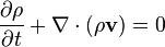
Conservation of mass
- Also termed continuity, this fundamental equation written in general form is as follows:
Conservation of momentum
- Also termed the Navier–Stokes equations, this fundamental is derivable from Newton's second law when applied to fluid motion. Written in compressible form for a Newtonian fluid, this equation may be written as follows:

Conservation of energy
- The First Law of Thermodynamics
is the statement of the conservation of energy. Under specific
conditions, the operation of a Centrifugal compressor is considered a
reversible process. For a reversible process, the total amount of heat
added to a system can be expressed as
 where is temperature and
  is entropy. Therefore, for a reversible process:
- Since U, S and V are thermodynamic functions of state, the above relation holds also for non-reversible changes. The above equation is known as the fundamental thermodynamic relation.
Equation of state
- The classical ideal gas law may be written:

- The ideal gas law may also be expressed as follows

- where
 is the density,
  is the adiabatic index (ratio of specific heats),
  is the internal energy per unit mass (the "specific internal energy"),
  is the specific heat at constant volume, and
  is the specific heat at constant pressure.
- With regard to the equation of state, it is important to remember that while air and nitrogen properties (near standard atmospheric conditions) are easily and accurately estimated by this simple relationship, there are many centrifugal compressor applications where the ideal relationship is inadequate. For example, centrifugal compressors used for large air conditioning systems (water chillers) use a refrigerant as a working gas that cannot be modeled as an ideal gas. Another example are centrifugal compressors design and built for the petroleum industry. Most of the hydrocarbon gases such as methane and ethylene are best modeled as a real gas equation of state rather than ideal gases.
-

Tidak ada komentar:
Posting Komentar