e- Tuner of modern electronic tuner AMNIMARJESLOW GOVERNMENT 91220017 XI XAM PIN PING HUNG CHOP 02096010014 LJBUSAF electronic tuner circuit series YES OF JESS PIT THE Satellite Trigger for Communication electronic interface ___ Lord Jesus Blessing ___ Gen. Mac Tech Zone Thor $
Tuning a radio with an analog tuner works: turning the dial physically changes the length of the antenna, which determines which broadcast wavelength will resonate in the antenna and get picked up. In contrast, what is the mechanism that makes a digital tuner work? My guess is it'll be some clever little circuit that somehow selects a resonant frequency by changing the amount of current going through it (or something like that).
In the early days of radio, the resonance of the antenna in combination with its associated inductive and capacitive properties was indeed the item which "dialed in" the frequency you wanted to listen to. You didn't actually change the length of the antenna, but by changing the inductor (a coil) or capacitor connected to the antenna you tuned the resonance. The output signal is an alternating voltage, and by rectifying it with a diode (called a "crystal" then..) you could extract a signal modulated as a varying amplitude of the carrier wave. All this without any battery!
But actually the antenna in a normal modern radio is not the component that "dials in" the selected broadcast frequency. The antenna circuit should indeed have a resonance within the band of frequencies you are interested in but this wide-band signal is then mixed with an internally generated sinusodial signal in the radio in an analog component, this subtracts the frequencies and lets the rest of the radio operate on a much easily handled frequency band (called the intermediate frequency). It is in the mixer you tune the reception in a modern superheterodyne radio receiver. It is much easier to synthesize an exact mixing frequency to tune with than to change the resonance of the antenna circuit.
The rest is not really physics, but the difference between an analog and a digital radio comes in the circuits after this and basically an analog radio extracts a modulation from the intermediate frequency which is amplified and sent to the speakers or radio output. In a digital radio, the signal represents a digital version of the audio, just like a WAV or MP3-file on a computer is a digital representation which can be turned back into an analog signal you can send to a speaker. The benefit of this is that the digital signal requires (potentially) less bandwidth in the air so you can fit more signals in the same "airspace" and that the digital signal can be less susceptible to noise. I write "can", because unfortunately many commercial digital radio/TV stations don't do this to improve the viewing or listening quality but just to fit in more content.
Let me reiterate that in a "digital" radio, the component that selects the reception frequency is still analog but the mixing (tuning) frequency is digitally controlled and selected.
There is also a very interesting thing called Software Defined Radio, SDR, which is the principle where the intermediate frequency (or in some cases the antenna frequency directly) is turned into a digital signal and demodulated by a signal processor which is completely software-up gradeable. Since it is much easier to program new software than to solder electronic components around, this created large interest in the radio hobby community where you can completely change the properties of a radio receiver just by downloading someone else's software from the net or write a new one yourself.
If you include SDR, and apply it without any intermediate frequency (take the antenna directly to an analog/digital converter and into a signal processor), you do indeed have a purely software-way of tuning your source like you ask for, although this is not how the most common digital radios work currently.
More complex transmissions like PAL/NTSC (TV), DAB (digital radio), DVB-T/DVB-S/DVB-C (digital TV) etc. use a wider frequency bandwidth, often with several subcarriers. These are transmitted inside the receiver as an intermediate frequency (IF). The next step is usually either to process subcarriers like real radio transmissions or to sample the whole bandwidth with A/D at a rate faster than the Nyquist rate that is at least 2 times the IF frequency.
The tuner can also refer to a radio receiver or standalone audio component that are part of an audio system, to be connected to a separate amplifier. The verb tuning in radio contexts means adjusting the radio receiver to receive the desired radio signalcarrier frequency that a particular radio station uses.
Opened VHF/UHF tuner of a television set. The antenna connector is on the right.
The simplest tuner consists of an inductor and capacitor connected in parallel, where the capacitor or inductor is made to be variable. This creates a resonant circuit which responds to an alternating current at one frequency. Combined with a detector, also known as a demodulator (diode D1 in the circuit), it becomes the simplest radio receiver, often called a crystal set.
Older models would realize manual tuning by means of mechanically operated ganged variable capacitors. Often several sections would be provided on a tuning capacitor, to tune several stages of the receiver in tandem, or to allow switching between different frequency bands. A later method used a potentiometer supplying a variable voltage to varactor diodes in the local oscillator and tank circuits of front end tuner, for electronic tuning.
Modern radio tuners use a superheterodyne receiver with tuning selected by adjustment of the frequency of a local oscillator. This system shifts the radio frequency of interest to a fixed frequency so that it can be tuned with fixed-frequency band-pass filter. Still later, phase locked loop methods were used, with microprocessor control.
In a self-contained radio receiver for audio, the signal from the detector after the tuner is run through a volume control and to an amplifier stage. The amplifier feeds either an internal speaker or headphones. In a tuner component of an audio system (for example, a home high-fidelity system or a public address system in a building), the output of the detector is connected to a separate external system of amplifiers and speakers.
The broadcast audio FM band (88 - 108 MHz in most countries) is around 100 times higher in frequency than the AM band and provides enough space for a bandwidth of 50 kHz. This bandwidth is sufficient to transmit both stereo channels with almost the full hearing range. Sometimes, additional subcarriers are used for unrelated audio or data transmissions. The left and right audio signals must be combined into a single signal which is applied to the modulation input of the transmitter; this is done by the addition of an inaudible subcarrier signal to the FM broadcast signal. FM stereo allows left and right channels to be transmitted. The availability of FM stereo, a quieter VHF broadcast band, and better fidelity led to the specialization of FM broadcasting in music, tending to leave AM broadcasting with spoken-word material.
Restoration
Standalone audio stereo FM tuners are sought after for audiophile and TV/FM DX applications, especially those produced in the 1970s and early 1980s, when performance and manufacturing standards were among the highest. In many instances the tuner may be modified to improve performance. A growing hobby trend is the electronics specialists that buy, collect and restore these vintage FM or AM/FM audio tuners. The restoration usually begins with replacing the electrolytic capacitors that may age over time. The tuner is outfitted with improved tolerance and better sounding upgraded parts. Prices have increased relative to the increasing demand for the older audio tuners. Those with the most value are the best sounding, most rare (collectible), the best DX capable (distance reception) and the known build quality of the component, as it left the factory.
AM/FM
Most of the early tuner models were designed and manufactured to receive only the AM broadcast band. As FM became more popular, the limitations of AM became more apparent, and FM became the primary listening focus, especially for stereo and music broadcasting. Few companies even manufacture dedicated FM or AM/FM tuners now, as these bands are most often included in a low cost chip for A/V systems, more as an afterthought, rather than designed for the critical FM listener.
In Europe, where a second AM broadcast band is used for longwave broadcasting, tuners may be fitted with both the standard medium wave and the additional longwave band. However, radios with only medium wave are also common, especially in countries where there are no longwave broadcasters. Rarely, radios are sold with only FM and longwave, but no medium wave band. Some tuners may also be equipped with one or more short wave bands.
Before the use of solid-state frequency synthesizers, covering the broad range of TV signal frequencies with a single tuned circuit and sufficient precision was uneconomic. Television channel frequencies were non-contiguous, with many non-broadcast services interleaved between VHF channels 6 and 7 in North America, for example. Instead, TV tuners of the era incorporated multiple sets of tuned circuits for the main signal path and local oscillator circuit. These "turret" tuners mechanically switched the receiving circuits by rotating a knob to select the desired channel. Channels were presented in fixed sequence, with no means to skip channels unused in a particular area. When UHF TV broadcasting was made available, often two complete separate tuner stages were used, with separate tuning knobs for selection of VHF band and UHF band channels. To allow for a small amount of drift or misalignment of the tuner with the actual transmitted frequency, tuners of that era included a "fine tuning" knob to allow minor adjustment for best reception. The combination of high frequencies, multiple electrical contacts, and frequent changing of channels in the tuner made it a high maintenance part of the television receiver, as relatively small electrical or mechanical problems with the tuner would make the set unusable.
VHF/UHF TV tuners are rarely found as a separate component, but are incorporated into television sets. Cable boxes and other set top boxes contain tuners for digital TV services, and send their output via SCART or other connector, or using an RF modulator (typically on channel 36 in Europe and channel 3/4 in North America) to TV receivers that do not natively support the services. They provide outputs via composite, S-video, or component video. Many can be used with video monitors that do not have a TV tuner or direct video input. They are often part of a VCR or digital video recorder (DVR, PVR). Many home computers in the 1970s and 1980s used an RF modulator to connect to a TV set.
Personal computers may be fitted with expansion cards (typically with PCI or USB interface) providing a TV tuner and digital signal processor (DSP). They may be dedicated TV tuner cards, or incorporated into a video card. These cards allow a computer to display and capture television programs. Many earlier models were stand-alone tuners, designed only to deliver TV pictures through a VGA connector; this allowed viewing television on a computer display, but did not support recording television programs.
An electronic tuner is a device which tunes across a part of the radio frequency spectrum by the application of a voltage or appropriate digital code words. This type of tuner supersedes mechanical tuners, which were tuned by manual adjustment of capacitance or inductance in the tuned circuits. In a more practical and everyday sense, a radio or television set which is tuned by manually turning a knob or dial contains a manual tuner into which the shaft of that knob or dial extends.
Early model televisions and radios were tuned by a rack of buttons; some of the earlier types were purely mechanical and adjusted the capacitance or inductance of the tuned circuit to a preset number of positions corresponding to the frequencies of popular local stations. Later electronic types used the varactor diode as a voltage controlled capacitance in the tuned circuit, to receive a number of preset voltages from the rack of buttons tuning the device instantly to local stations. The mechanical button rack was popular in car radios of the 1960s and 1970s. The electronic button rack controlling the new electronic varactor tuner was popular in television sets of the 1970s and 1980s.
Modern electronic tuners also use varactor diodes as the actual tuning elements, but the voltages which change their capacitance are obtained from a digital to analog converter (DAC) driven by a microprocessor or phase locked loop (PLL) arrangement. This modern form allows for very precise tuning and locking-in on weak signals, as well as a numerical display of the tuned frequency.
On June 12, 2009, all full-power analog television transmissions ended in the United States. Viewers who watch broadcast television on older analog TV sets must use a DTA. Since many of the low-power TV stations will continue to broadcast in analog for years to come, consumers who watch low-power stations will need an adapter with an analog pass through feature that allows the viewer to watch both digital and analog signals. Viewers who receive their television signals through cable or satellite were not affected by this change and did not need a digital television adapter (however, see the cable TV exception below). Additionally, viewers who have newer televisions with built-in digital ATSC tuners will not need an external digital television adapter.
The United States government had set up a program to offer consumers a $40 "coupon" which could be used toward the purchase of a coupon-eligible converter box; that program ended in July 2006.
Flash Back
At the Consumer Electronics Association's Entertainment Technology Policy Summit in January 2006, Federal Communications Commission (FCC) CommissionerJonathan Adelstein said many Americans did not know about the February 17, 2006, deadline for ending analog TV. Furthermore, he said, too many people were still buying analog TV sets, meaning more demand for converter boxes. And even if people found out what they would have to do, converter boxes might not do the job adequately. Tribune Broadcasting chief technology officer Ira Goldstone said just buying a converter box did not necessarily mean getting the latest technology. Bob Seidel of CBS said companies (especially in countries other than the US) might use cheaper tuners, and people would need new television antennas for proper reception. Circuit City Chairman Alan McCollough opposed converter boxes, saying people should just buy digital TVs, and television networks should offer only widescreen-format television programming as an incentive to do that.[1]
Cable TV systems are under no deadline to convert to digital TV. However, many Comcast (and some other cable TV) customers are finding all of their non-local and non-shopping networks eliminated on various dates, even though only a few are needed for additional digital cable channels. CECBs (Coupon-eligible converter boxes) will not work on these systems because cable ATSC uses 256QAMmodulation instead of 8VSB, and so a separate but similar DTA with a QAM tuner is necessary. If the cable company takes away analog channels, at least two of these adapters must be provided for free by the cable company for at least three years so that customers can continue to watch the same channels with existing equipment. Cable companies were required to provide some analog service until October 2006. After that, taking away analog channels allowed faster Internet and more HD channels. An adapter from the cable provider was needed even for digital TVs if the company scrambled its digital signals to prevent piracy.
A digital transport adapter will allow viewing of basic channels, often as many as 99, but not premium channels. It will also not allow video on demand or pay-per-view. Simple DTAs only allow analog sets to receive digital signals using RF output on channel 3 or 4, using coaxial cable. Other versions of the DTA are available.[5]
Pace plc developed the XiD-P digital transport adapter for Comcast, allowing 4K service and offering the potential to expand the DTA from one-way to two-way. This would involve adding IP capability
TV gateway
A TV gateway (also called network TV tuner) is a television headend to a network UPnP router that receives live digital video broadcast (DVB) MPEG transport streams (channels) from terrestrial aerials, satellite dishes, or cable feeds and converts them into IP streams for distribution over an IP network.
TV Gateway - VBox
TV gateways allow users to stream broadcast live TV content to connected devices on the IP network, including tablets, smartphones, computers, gaming consoles and smart tvs. They also allow multiple users to watch and record different channels at the same time.
The device offers multi-platform, multi-screen broadcast television with rich live TV content and high quality HD channels.
Digital TV signals used in TV gateways
Most TV gateways support free-to-air (FTA) television services found in many countries. These include services such as Freeview and Freesat in the United Kingdom,TNT in France and TDT in Spain, and basic cable packages in Germany, Switzerland, Austria, and others.
A few TV gateways also support third party conditional access modules (CAMs) for premium pay TV channels, which are transmitted by using a CAM CI card provided by the broadcasters or by third party manufacturers to access their TV service.
While many first-generation TV gateways support only one channel or a limited number of channels, modern TV gateways provide multiple TV tuners that can process several channels simultaneously. The more channels a TV gateway provides the more users it can service at the same time. Modern TV gateways also allow users to record TV programs to a USB flash drive, or external hard disk and in some cases, shared folders or network attached storage (NAS).
Electronic program guide
An electronic program guide (EPG) is like a traditional TV listing magazine but available online or on a TV service like aerial, satellite or cable. It allows viewers to find out what shows will air and search for programs they’d like to watch. EPG's also allow users to set reminders and record shows automatically.[4]
Most TV gateways with PVR functionality offer EPG data. This can be free of charge for data processed from the broadcaster TV stream (according to standard DVB EN 300 468 and technical specification TS 101 211) or via a paid service provided by a third party online EPG provider.
Whole house DVR
Whole house HD-digital video recorder allows users to record programs on a centralized TV gateway DVR and then watch them on any device connected to their home network.
TV gateways with whole house HD-DVR require storage to record live TV programs or schedule future recordings using the EPG.
Whole house DVR TV gateways use a number of storage mediums to store recordings:
Attached USB storage such as removable HDD or USB flash drives
Unicast (HTTP) protocols are mainly used in consumer grade TV gateways to provide a small number of simultaneous users with the flexibility to view multiple channels.
Multicast (UDP), is mainly used in professional-grade TV gateways to enable efficient broadcast of a preset number of channels to a large number of simultaneous viewers. Multicast TV gateways are used primarily by IPTV broadcasters, hotels, hospitals, and digital signage applications.
M3U - The m3u8 file format is a de facto standard playlist format suitable for carrying lists of media file URL. Advanced TV gateways use M3U in addition to UPnP to offer better application support, allowing for faster channel zapping and provide a preset channel list.
XO___XO The Concept of Electronic Tuning
Instead of the capacitor CR, that was used for fine tuning in the previous project, a capacitive (varicap) diode can be used. It’s a special HF diode which is polarized by exposing it to DC voltage in order to be non-permeable (+ to the anode, - to cathode). By changing the voltage diode’s capacitance also changes, which allows for it to be utilized as variable capacitor. If, acc. to pic.5.13-a, the DC voltage between the cathode and anode (UAK) varies from U1 to U2, diode’s capacitance goes from Cmax till Cmin.The electronic diagram for the electronic fine tuning circuitry is given on pic.5.13-b. Diode capacitance is changed by moving the slider of the P1 potentiometer. By means of trimmer TP the necessary Cmax is set, and when this is done TP can be replaced by an ordinary resistor. All the components are mounted on the PCB, together with other parts of the receiver, except the P1. It is mounted on the front panel, and connected to the PCB with 3 ordinary wires.* The variable capacitors that were used for tuning in all the receivers described so far are solid, lasting, reliablecomponents. Their mishap is they are hard to purchase, they are quite robust (compared to other device components), and their mounting isn’t simple because the shaft for the knob must go through the front plate of the device box. That is why varicap diodes are also replacing them. With the diode that has Cmax/Cmin ratio that is big enough, say, Cmax/Cmin>15, the circuit form pic.5.13 can be used as the variable capacitor (C is simply omitted). In that case, some bigger knob with an arrow is mounted on the P1 handle, and numbers from 1 to 10 are written on the panel, as shown on pic.5.13. This scale allows the listeners to see what station is the receiver tuned at. Of course, for the MW band, the numbers as those on pic.3.7 can also be written.* In case of SW band, the P2 potentiometer is added for fine tuning.The optical indication of the tuning, with and knob with arrow is the simplest solution possible. More prettier one is using a small movable-coil instrument (V), such as those used as battery indicators in industrial devices, or for tuning indication and similar. The connecting is done acc. to the diagram on the left part of the pic.5.13-c. In series with the instrument, the TP potentiometer is attached. Its resistance depends on the maximum instrument current, and can be found experimentally. For start, you may use a 1 MOhm linear trimmer, with its slider at lowest position (so that its resistance is maximum). Put the P1 slider also at the lowest position. Turn on the receiver. Start moving the P1slider upwards, and observe the instrument needle. if it soon goes to the end, you’ll have to take a trimmer with greater resistance or to add another resistor in series with it, so that when the P1 slider gets to its rightmost position, the needle goes somewhere around the middle of the full scale. If the needle, with P1 in topmost position, moves too little, you’ll need a smaller resistance trimmer. When you succeed in having the needle in the middle of the scale with P1 in topmost position, start moving the TP slider until the needle reaches the end of scale. The circuit is well adjusted if the needle goes from zero to full scale while P1 slider is moved from bottommost to topmost position. The instrument can have any shape, but the most appropriate (and cheapest) is square, like the one on the picture.
Tuned circuit, any electrically conducting pathway containing both inductive and capacitive elements. If these elements are connected in series, the circuit presents low impedance to alternating current of the resonant frequency, which is determined by the values of the inductance and capacitance, and high impedance to current of other frequencies.
In a parallel-connected tuned circuit, the impedance is high at the resonant frequency, low at others.
Make A USB TV Tuner To Watch TV On Your Laptop!
Watching your favorite TV channel on a laptop, PC or smartphone is easier than you might think. Instead of buying a TV tuner box, you could make your own TV tuner which can be plugged directly into any free USB port of your PC or laptop.
If you want to know the detailed design of USB TV tuners, here are some ready-to-use reference designs with complete documentation. Take a look!
USB TV Tuner with Low-power MCU:
This reference design helps you in developing your own USB TV dongle to view TV channels on a personal computer or laptop. The design is based on low-power USB microcontroller FX2LP from Cypress and a Legend Silicon’s demodulator. A tuner from ADI tunes the RF signal and sends it to the demodulator. The resultant TV signals in MPEG2_TS stream are then sent to the microcontroller, which then sends them to the PC through the USB interface. In the PC, a Media Player application plays this data. This reference design has been tested with Windows XP/32 bit platform. The design comes equipped with complete documentation, namely, schematics, gerber files, bill of materials, firmware source code, driver object code and reference design guide.
USB Dongle for Digital TV Broadcast:
This USB reference design is for handheld digital video broadcast (DVB-H) applications on computers, laptops and other portable/handheld devices. The design is built around a MAX2165 direct-conversion tuner IC designed for digital video broadcast applications. The tuner covers a 470MHz to 780MHz input frequency range. It helps to reduce overall BOM cost and comes in a tiny package. The MAX2165 allows a programmable channel-selection allowing for operation with 7MHz and 8MHz channels. Other components used in the design are a DMB-TH demodulator and USB interface. The DMB-TH demodulator accepts inputs from the tuner and provides a MPEG-2 stream to the USB chip. The USB chip enables interfacing with a laptop or desktop for viewing broadcast video and for lab analysis .
Electronic tuner
In music, an electronic tuner is a device that detects and displays the pitch of musical notes played on a musical instrument. "Pitch" is the highness or lowness of a musical note, which is typically measured in Hertz. Simple tuners indicate—typically with an analog needle-dial, LEDs, or an LCD screen—whether a pitch is lower, higher, or equal to the desired pitch. In the 2010s, software applications can turn a smartphone, tablet, or personal computer into a tuner. More complex and expensive tuners indicate pitch more precisely. Tuners vary in size from units that fit in a pocket to 19" rack-mount units. Instrument technicians and piano tuners typically use more expensive, accurate tuners.[1]
The simplest tuners detect and display tuning only for a single pitch—often "A" or "E"—or for a small number of pitches, such as the six used in the standard tuning of a guitar (E,A,D,G,B,E). More complex tuners offer chromatic tuning for all 12 pitches of the equally tempered octave. Some electronic tuners offer additional features, such as pitch calibration, temperament options, the sounding of a desired pitch through an amplifier plus speaker, and adjustable "read-time" settings that affect how long the tuner takes to measure the pitch of the note.
Among the most accurate tuning devices, strobe tuners work differently than regular electronic tuners. They are stroboscopes that flicker a light at the same frequency as the note. The light shines on a wheel that spins at a precise speed. The interaction of the light and regularly-spaced marks on the wheel creates a stroboscopic effect that makes the marks for a particular pitch appear to stand still when the pitch is in tune. These can tune instruments and audio devices more accurately than most non-strobe tuners. However, mechanical strobe units are expensive and delicate, and their moving parts require periodic servicing, so they are used mainly in applications that require higher precision, such as by professional instrument makers and repair experts.
Pocket-sized Korg chromatic LCD tuner, with simulated analog indicator needle
Regular types
Regular electronic tuners contain either an input jack for electric instruments (usually a 1/4" patch cord input), a microphone, or a clip-on sensor (e.g., a piezoelectricpickup) or some combination of these inputs. Pitch detection circuitry drives some type of display (an analog needle, an LCD simulated image of a needle, LED lights, or a spinning translucent disk illuminated by a strobing backlight). Some tuners have an output, or through-put, so the tuner can connect 'in-line' from an electric instrument to an instrument amplifier or mixing console. Small tuners are usually battery powered. Many battery powered tuners also have a jack for an optional AC power supply.
Some rock and pop guitarists and bassists use "stompbox" format electronic tuners that route the electric signal for the instrument through the unit via a 1/4" patch cable. These pedal-style tuners usually have an output so that the signal can be plugged into a guitar amp.
Most musical instruments generate a fairly complex waveform. It contains a number of harmonic partials, including the fundamental frequency (which a typical listener perceives as the pitch of the note) and additional "harmonics" (also called "partials" or "overtones"). Each instrument produces different ratios of harmonics, which is what makes notes of the same pitch played on different instruments (e.g., an A 440 Hz note played on oboe, violin or electric guitar) sound different. As well, this waveform constantly changes. This means that for non-strobe tuners to be accurate, the tuner must process a number of cycles and use the pitch average to drive its display. Background noise from other musicians or harmonic overtones from the musical instrument can impede the electronic tuner from "locking" onto the input frequency. This is why the needle or display on regular electronic tuners tends to waver when a pitch is played. Small movements of the needle, or LED, usually represent a tuning error of 1 cent. Typical accuracy of these types of tuners is around +/- 3 cents. Some inexpensive LED tuners may drift by as much as +/- 9 cents.
"Clip-on" tuners typically attach to instruments with a spring-loaded clip that has a built-in contact microphone. Clipped onto a guitar headstock or violin scroll, these sense pitch even in loud environments, for example when other people are tuning.
Some guitar tuners fit into the instrument itself. Typical of these are the Sabine AX3000 and the "NTune" device. The NTune consists of a switching potentiometer, a wiring harness, illuminated plastic display disc, a circuit board and a battery holder. The unit installs in place of an electric guitar's existing volume knob control. The unit functions as a regular volume knob when not in tuner mode. To operate the tuner, the player pulls the volume knob up. The tuner disconnects the guitar's output so the tuning process is not amplified. The lights on the illuminated ring, under the volume knob, indicate the note being tuned. When the note is in tune a green "in tune" indicator light illuminates. After tuning is complete the musician pushes the volume knob back down, disconnecting the tuner from the circuit and re-connecting the pickups to the output jack.
Gibson guitars released a guitar model in 2008 called the Robot Guitar—a customized version of either the Les Paul or SG model. The guitar is fitted with a special tailpiece with in-built sensors that pick up the frequency of the strings. An illuminated control knob selects different tunings. Motorized tuning machines on the headstock automatically tune the guitar. In "intonation" mode, the device displays how much adjustment the bridge requires with a system of flashing LEDs on the control knob.
The first automated guitar tuner was invented by JD Richard in 1982 while studying Electrical Engineering at the University of New Brunswick, New Brunswick Canada. This tuner was based on phase-locked-looped feedback design that listened to the frequency of the string and turned a stepper motor (with a 400/1 gear ratio) attached to the tuning peg of the guitar. This first design never went into production although the thesis paper can still be obtained at the university. (Ref: UNB, Canada, Department of Electrical Engineering, Paper "Automated Guitar Tuner by J.D. Steven Richard - April 1982"; Supervisor Dr. J.P. Burgess)
Regular needle, LCD and LED display tuners
A needle, LCD or regular LED type tuner uses a microprocessor to measure the average period of the waveform. It uses that information to drive the needle or array of lights. When the musician plays a single note, the tuner senses the pitch. The tuner then displays the pitch in relation to the desired pitch, and indicates whether the input pitch is lower, higher, or equal to the desired pitch. With needle displays, the note is in tune when the needle is in a 90° vertical position, with leftward or rightward deviations indicating that the note is flat or sharp, respectively. Tuners with a needle are often supplied with a backlight, so that the display can be read on a darkened stage.
For block LED or LCD display tuners, markings on the readout drift left if the note is flat and right if the note is sharp from the desired pitch. If the input frequency is matched to the desired pitch frequency the LEDs are steady in the middle and an 'in tune' reading is given.
Some LCDs mimic needle tuners with a needle graphic that moves in the same way as a genuine needle tuner. Somewhat misleadingly, many LED displays have a 'strobe mode' that mimics strobe tuners by scrolling the flashing of the LEDs cyclically to simulate the display of a true strobe. However, these are all just display options. The way a regular tuner 'hears' and compares the input note to a desired pitch is exactly the same, with no change in accuracy. For more on how strobe tuners work see the dedicated section.
The least expensive models only detect and display a small number of pitches, often those pitches that are required to tune a given instrument (e.g., E, A, D, G, B, E of standard guitar tuning). While this type of tuner is useful for bands that only use stringed instruments such as guitar and electric bass, it is not that useful for tuning brass or woodwind instruments. Tuners at the next price point offer chromatic tuning, the ability to detect and assess all the pitches in the chromatic scale (e.g., C, C♯, D, D♯, etc.). Chromatic tuners can be used for B♭ and E♭ brass instruments, such as saxophones and horns. Many models have circuitry that automatically detects which pitch is being played, and then compares it against the correct pitch. Less expensive models require the musician to specify the target pitch via a switch or slider. Most low- and mid-priced electronic tuners only allow tuning to an equal temperament scale.
Electric guitar and electric bass players who perform concerts may use electronic tuners built into an effects pedal, often called a stomp box. These tuners have a rugged metal or heavy-duty plastic housing and a foot-operated switch to toggle between the tuner and a bypass mode. Professional guitarists may use a more expensive version of the LED tuner mounted in a rack-mount case with a larger range of LEDs for more accurate pitch display. Many models let the user select reference pitches other than A440. On many electronic tuners, the user can select a different note—useful for, for example, dropping a guitar's tuning to a lower pitch (e.g., Dropped tuning). Some models are adjustable standards other than A=440. This is useful to some Baroque musicians who play period instruments at lower reference pitches—such as A=435. Some higher-priced electronic tuners support tuning to a range of different temperaments—a feature useful to some guitarists and harpsichord players.
Some expensive tuners also include an on-board speaker that can sound notes, either to facilitate tuning by ear or to act as a pitch reference point for intonation practice. Some expensive tuners provide an adjustable read time that controls at what time interval the circuitry assesses pitch. The combination of all the above features makes some tuners preferable for tuning instruments in an orchestra. These are sometimes called "orchestral tuners".
Clip-on
A clip-on tuner attaches to the instrument and senses the vibrations from the instrument, even in a noisy environment.
A clip-on tuner clips on to an instrument—such as onto the headstock of a guitar or the bell of a trombone. A vibration sensor built into the clip transmits the instrument vibrations to the tuning circuitry. The absence of a microphone makes these tuners immune to background noise, so musicians can tune in noisy environments, including while other musicians are tuning. The clip-on tuner was invented in 1995 by Mark Wilson of OnBoard Research Corporation, which marketed it as The Intellitouch Tuner Model PT1.
Apps
Many chromatic and guitar tuner apps are available for Android and iOS smartphones. Many are free to download and install.
Strobe tuners
Strobe tuners (the popular term for stroboscopic tuners) are the most accurate type of tuner. There are three types of strobe tuners: the mechanical rotating disk strobe tuner, an LED array strobe in place of the rotating disk, and "virtual strobe" tuners with LCDs or ones that work on personal computers. A strobe tuner shows the difference between a reference frequency and the musical note being played. Even the slightest difference between the two shows up as a rotating motion in the strobe display. The accuracy of the tuner is only limited by the internal frequency generator. The strobe tuner detects the pitch either from a TRS input jack or a built-in or external microphone connected to the tuner.
The first strobe tuner dates back to 1936 and was originally made by the Conn company; it was called the Stroboconn and was produced for approximately 40 years. However, these strobes are now mainly collector pieces. They had 12 strobe discs, driven by one motor. The gearing between discs was a very close approximation to the 12th root of two ratio. This tuner had an electrically driven temperature-compensated tuning fork; the electrical output of this fork was amplified to run the motor. The fork had sliding weights, an adjustment knob, and a dial to show the position of the weights. These weights permitted setting it to different reference frequencies (such as A4 = 435 Hz), although over a relatively narrow range, perhaps a whole tone. When set at A4 = 440 Hz the tuning fork produced a 55 Hz signal, which drove the four-pole 1650 RPM synchronous motor to which the A disc was mounted. (The other discs were all gear-driven off of this one.) Incoming audio was amplified to feed a long neon tube common to all 12 discs. Wind instrument repair people liked this tuner because it needed no adjustment to show different notes. Anyone who had to move this tuner around was less inclined to like it because of its size and weight: two record-player-sized cases of 30-40 pounds each.
The best known brand in strobe tuner technology is Peterson Tuners who in 1967 marketed their first strobe tuner, the Model 400. Other companies, such as Sonic Research, TC Electronic, and Planet Waves, sell highly accurate LED-based true strobe tuners. Other LED tuners have a 'strobe mode' that emulates the appearance of a strobe. However, the accuracy of these tuners in strobe mode, while sufficient for most tuning, is no better than in any other mode, as they use the same technique as any basic tuner to measure frequency, only displaying it in a way that imitates a strobe tuner.
How it works
Mechanical strobe tuners have a series of lamps or LEDs powered by amplified audio from the instrument; they flash (or strobe) at the same frequency as the input signal. For instance an 'A' played on a guitar's 6th string at the 5th fret has the frequency of 110 Hz when in tune. An 'A' played on the 1st string at the 5th fret vibrates at 440 Hz. As such, the lamps would flash either 110 or 440 times per second in the above examples. In front of these flashing lights is a motor-driven, translucent printed disc with rings of alternating transparent and opaque sectors.
This disc rotates at a fixed specific speed, set by the user. Each disc rotation speed is set to a particular frequency of the desired note. If the note being played (and making the lamps behind the disc flash) is at exactly the same frequency as the spinning of the disc, then the disc appears to be static (due to the persistence of vision) from the strobing effect. If the note is out of tune then the pattern appears to be moving as the light flashing and the disc rotation are out of sync from each other. The more out of tune the played note is, the faster the pattern seems to be moving, although in reality it always spins at the same speed for a given note. Many good turntables for vinyl disc records have stroboscopic patterns lit by the incoming AC power (mains). The power frequency, either 50 or 60 Hz, serves as the reference, although commercial power frequency sometimes changes slightly (a few tenths of a percent) with varying load. Unless reference and measured quantity are interchanged, the operating principle is the same; the turntable speed is adjusted to stop drifting of the pattern.
Pattern of a mechanical strobe tuner disc
As the disc has multiple bands, each with different spacings, each band can be read for different partials within one note. As such, extremely fine tuning can be obtained, because the user can tune to a particular partial within a given note. This is impossible on regular needle, LCD or LED tuners. The strobe system is about 30 times more accurate than a quality electronic tuner, being accurate to 1/10 of a cent. Advertisements for the Sonic Research LED strobe claim that it is calibrated to ± 0.0017 cents and guaranteed to maintain an accuracy of ± 0.02 cents or 1/50 of a cent.
Strobe units can often be calibrated for many tunings and preset temperaments and allow for custom temperament programming, stretched tuning, "sweetened" temperament tunings and Buzz Feiten tuning modifications. Due to their accuracy and ability to display partials even on instruments with a very short "voice" (e.g., notes of short duration), strobe tuners can perform tuning tasks that would be very difficult, if not impossible, for needle-type tuners. For instance, needle/LED display type tuners cannot track the signal to identify a tone of the Caribbean steelpan (often nicknamed the "steeldrum") due to its very short "voice". A tuner needs to be able to detect the first few partials for tuning such an instrument, which means that only a strobe tuner can be used for steelpan tuning. This is also true of the comb teeth used in mechanical musical instruments like Music Boxes and the like. In such cases a technician has to physically remove metal from the tooth to reach the desired note. The metal teeth only resonates briefly when plucked. Great accuracy is required as once the metal is cut or filed away, the lost material cannot be replaced. As such, the strobe-type tuners are the unit of choice for such tasks. Tuners with an accuracy of better than 0.2 cent are required for guitar intonation tuning.
One of the most expensive strobe tuners is the Peterson Strobe Center, which has twelve separate mechanical strobe displays; one for each pitch of the equally tempered octave. This unit (about $3,500 US) can tune multiple notes of a sound or chord, displaying each note's overtone sub-structure simultaneously. This gives an overall picture of tuning within a sound, note or chord that is not possible with most other tuning devices. (The TC Electronic Polytune can display the pitch accuracy of up to six pre-selected notes.) It is often used for tuning complex instruments and sound sources, or difficult-to-tune instruments where the technician requires a very accurate and complete aural picture of an instrument's output. For instance, when tuning musical bells, this model displays several of the bell's partials (hum, second partial, tierce, quint and nominal/naming note) as well as the prime, and each of their partials, on separate displays. The unit is heavy and fragile, and requires a regular maintenance schedule. Each of the twelve displays requires periodic re-calibration. It can be used to teach students about note substructures, which show on the separate strobing displays.
Mechanical disc strobe tuners are expensive, bulky, delicate, and require periodic maintenance (keeping the motor that spins the disc at the correct speed, replacing the strobing LED backlight, etc.). For many, a mechanical strobe tuner is simply not practical for one or all of the above reasons. To address these issues, in 2001 Peterson Tuners added a line of non-mechanical electronic strobe tuners that have LCDdot-matrix displays mimicking a mechanical strobe disc display, giving a stroboscopic effect. In 2004 Peterson made a model of LCD strobe in a sturdy floor based "stomp box" for live on-stage use. Virtual strobe tuners are as accurate as standard mechanical disc strobe tuners. However, there are limitations to the virtual system compared to the disc strobes. Virtual strobes display fewer bands to read note information, and do not pick up harmonic partials like a disc strobe. Rather, each band on a virtual strobe represents octaves of the fundamental. A disc strobe provides "one band correspondence"—each band displays a particular frequency of the note being played. On the virtual strobe system, each band combines a few close frequencies for easier reading on the LCD. This is still extremely accurate for intoning and tuning most instruments—but, as of this writing, no virtual strobe tuner provides detailed information on partials.
Sonic Research and Planet Waves both released a true-strobe with a bank of LEDs arranged in a circle that gives a strobing effect based upon the frequency of the input note. Both LCD and LED display true strobes do not require mechanical servicing and are much cheaper than the mechanical types. As such, they are a popular option for musicians who want the accuracy of a strobe without the high cost and the maintenance requirements. However, LED strobe displays offer no information about the harmonic structure of a note, unlike LCD types, which do offer four bands of consolidated information.
Peterson released a PC-based virtual strobe tuner in 2008 called "StroboSoft". This computer software package has all the features of a virtual strobe, such as user-programmable temperaments and tunings. To use this tuner, a musician must have a computer next to the instrument to be tuned. An alternative is the PC-based strobe tuner TB Strobe Tuner with fewer functions.
In 2009 Peterson Tuners released a VirtualStrobe tuner as an end-user application add-on for Apple's iPhone and iPod Touch where the application is bought cheaply as a download and installed. There exists a special 1/4" TRS jack adapter for connecting an electric instrument to the iPhone, a notable achievement in strobe tuner technology, which has made such tuning widely available. In order to use it, however, a compatible iPod or iPhone must already be on hand.
As both mechanical and electronic strobes are still more expensive and arguably more difficult to use in order to achieve the desired results than ordinary tuners, their use is usually limited to those whose business it is accurately to intone and tune pianos, harps, and early instruments (e. g. harpsichords) on a regular basis: luthiers, instrument restorers and technicians – and instrument enthusiasts. These tuners make the intonation process more precise.
Uses
Classical music
Tuning of Sébastien Érard harp using Korg OT-120 Wide 8 Octave Orchestral Digital Tuner
In classical music, there is a longstanding tradition to tune "by ear", by adjusting the pitch of instruments to a reference pitch. In an orchestra, the oboe player gives a 440 Hz "A", and the different instrument sections tune to this note. In chamber music, either one of the woodwind players gives an "A", or if none is present, one of the string players, usually the first violinist, bows his or her open "A" string. If an orchestra is accompanying a piano concerto, the first oboist takes the "A" from the piano and then plays this pitch for the rest of the orchestra.
Despite this tradition of tuning by ear, electronic tuners are still widely used in classical music. In orchestras the oboist often uses a high-end electronic tuner to ensure that her/his "A" is correct. As well, other brass or woodwind players may use electronic tuners to ensure that their instruments are correctly tuned. Classical performers also use tuners off-stage for practice purposes or to check their tuning (or, with the further aid of a speaker, to practice ear training). Electronic tuners are also used in opera orchestras for offstage trumpet effects. In offstage trumpet effects, trumpet players performs a melody from the backstage or from a hallway behind the stage, creating a haunting, muted effect. Since trumpet players cannot hear the orchestra, they cannot know whether or not their notes are in tune with the rest of the ensemble; to resolve this problem, some trumpet players use a high-end, sensitive tuner so that they can monitor the pitch of their notes.
Piano tuners, harp makers and the builders and restorers of early instruments, e.g. harpsichords, use high-end tuners to assist with their tuning and instrument building. Even piano tuners who work mostly "by ear" may use an electronic tuner to tune just a first key on the piano, e. g. the a' to 440 Hz, after which they proceed by means of octaves, approximate fifths and approximate fourths to tune the others. (In the twelve-tone equal temperament system dominant in classical and Western music, all intervals except the octave are slightly "mistuned" or compromised compared to more consonant just intervals.) They may also use electronic tuners to get a very out-of-tune piano roughly in pitch, after which point they tune by ear. Electronic tuning devices for keyboard instruments are for various reasons generally much more complex and therefore expensive than in the case of other widely used instruments.
Popular and folk music
In popular music, amateur and professional bands from styles as varied as country and heavy metal use electronic tuners to ensure that the guitars and electric bass are correctly tuned. In popular music genres such as rock music, there is a great deal of stage volume due to the use of drums and guitar amplifiers, so it can be difficult to tune "by ear". Electronic tuners are helpful aids at jam sessions where a number of players are sharing the stage, because it helps all of the players to have their instruments tuned to the same pitch, even if they have come to the session halfway through. Tuners are helpful with acoustic instruments, because they are more affected by temperature and humidity changes. An acoustic guitar or upright bass that is perfectly in tune backstage can change in pitch under the heat of the stage lights and from the humidity from thousands of audience members.
Tuners are used by guitar technicians who are hired by rock and pop bands to ensure that all of the band's instruments are ready to play at all times. Guitar technicians (often called guitar techs) tune all of the instruments (electric guitars, electric basses, acoustic guitars, mandolins, etc.) before the show, after they are played, and before they are used onstage. Guitar techs also retune instruments throughout the show. Whereas amateur musicians typically use a relatively inexpensive quartz tuner, guitar technicians typically use expensive, high-end tuners such as strobe tuners. Most strobe tuners, counter-intuitively, also use quartz crystal oscillators as time references, although the responses are processed differently by the different units.
Bell tuning
Strobe tuners are used in the tuning of bells, which require accurate tuning of many partials. The removal of metal from various parts of the bell shape is by a tuning lathe, and once too much metal has been removed it cannot be reversed. Hence accurate approach to the desired tuning partial is essential to prevent overshoot.
Microtuner
A microtuner or microtonal tuner is an electronic device or software program designed to modify and test the tuning of musical instruments (in particular synthesizers) with microtonal precision, allowing for the design and construction of microtonal scales and just intonation scales, and for tuning intervals that may differ from those of common Western equal temperament. The term also indicates a high-precision mechanical tuning device found on some vintage Conn brand brass and reed instruments (mostly cornets and alto saxophones). These were first introduced with their 1918 catalog and manufactured until about 1954. Such devices were also offered with some vintage saxophones manufactured in Europe by Beaugnier, Dolnet, Hüller, Keilwerth and other famous makers in the same period.
Transport
Time-keeping and synchronization of clocks has been a critical problem in long-distance ocean navigation. Before radio navigation and satellite-based navigation, navigators required accurate time in conjunction with astronomical observations to determine how far east or west their vessel traveled. The invention of an accurate marine chronometer revolutionized marine navigation. By the end of the 19th century, important ports provided time signals in the form of a signal gun, flag, or dropping time ball so that mariners could check their chronometers for error.
Synchronization was important in the operation of 19th century railways, these being the first major means of transport fast enough for differences in local time between adjacent towns to be noticeable. Each line handled the problem by synchronizing all its stations to headquarters as a standard railroad time. In some territories, sharing of single railroad tracks was controlled by the timetable.The need for strict timekeeping led the companies to settle on one standard, and civil authorities eventually abandoned local mean solar time in favor of that standard.
Communication
In electrical engineering terms, for digital logic and data transfer, a synchronous circuit requires a clock signal. However, the use of the word "clock" in this sense is different from the typical sense of a clock as a device that keeps track of time-of-day; the clock signal simply signals the start and/or end of some time period, often very minute (measured in microseconds or nanoseconds), that has an arbitrary relationship to sidereal, solar, or lunar time, or to any other system of measurement of the passage of minutes, hours, and days.
In a different sense, electronic systems are sometimes synchronized to make events at points far apart appear simultaneous or near-simultaneous from a certain perspective. (Albert Einstein proved in 1905 in his first relativity paper that there actually are no such things as absolutely simultaneous events.) Timekeeping technologies such as the GPS satellites and Network Time Protocol (NTP) provide real-time access to a close approximation to the UTC timescale and are used for many terrestrial synchronization applications of this kind.
Synchronization is an important concept in the following fields:
Synchronization of multiple interacting dynamical systems can occur when the systems are autonomous oscillators. For instance, integrate-and-fire oscillators with either two-way (symmetric) or one-way coupling can synchronize when the strength of the coupling (in frequency units) is greater than the differences among the free-running natural oscillator frequencies. Poincare phase oscillators are model systems that can interact and partially synchronize within random or regular networks.[1] In the case of global synchronization of phase oscillators, an abrupt transition from unsynchronized to full synchronization takes place when the coupling strength exceeds a critical threshold. This is known as the Kuramoto model phase transition. Synchronization is an emergent property that occurs in a broad range of dynamical systems, including neural signaling, the beating of the heart and the synchronization of fire-fly light waves.
Human movement
Synchronization of movement is defined as similar movements between two or more people who are temporally aligned. This is different to mimicry, as these movements occur after a short delay.[3]Muscular bonding is the idea that moving in time evokes particular emotions.[4] This sparked some of the first research into movement synchronization and its effects on human emotion.
In groups, synchronization of movement has been shown to increase conformity,[5] cooperation and trust[6] however more research on group synchronization is needed to determine its effects on the group as a whole and on individuals within a group. In dyads, groups of two people, synchronization has been demonstrated to increase affiliation,[7] self-esteem,[8] compassion and altruistic behaviour[9] and increase rapport.[10] During arguments, synchrony between the arguing pair has been noted to decrease, however it is not clear whether this is due to the change in emotion or other factors.[11] There is evidence to show that movement synchronization requires other people to cause its beneficial effects, as the effect on affiliation does not occur when one of the dyad is synchronizing their movements to something outside the dyads . This is known as interpersonal synchrony.
There has been dispute regarding the true effect of synchrony in these studies. Research in this area detailing the positive effects of synchrony, have attributed this to synchrony alone; however, many of the experiments incorporate a shared intention to achieve synchrony. Indeed, the Reinforcement of Cooperation Model suggests that perception of synchrony leads to reinforcement that cooperation is occurring, which leads to the pro-social effects of synchrony.More research is required to separate the effect of intentionality from the beneficial effect of synchrony.
Uses
Film synchronization of image and sound in sound film.
Synchronization is important in fields such as digital telephony, video and digital audio where streams of sampled data are manipulated.
Arbiters are needed in digital electronic systems such as microprocessors to deal with asynchronous inputs. There are also electronic digital circuits called synchronizers that attempt to perform arbitration in one clock cycle. Synchronizers, unlike arbiters, are prone to failure. (See metastability in electronics).
Encryption systems usually require some synchronization mechanism to ensure that the receiving cipher is decoding the right bits at the right time.
Automotive transmissions contain synchronizers that bring the toothed rotating parts (gears and splined shaft) to the same rotational velocity before engaging the teeth.
Film, video, and audio applications use time code to synchronize audio and video.
Some systems may be only approximately synchronized, or plesiochronous. Some applications require that relative offsets between events be determined. For others, only the order of the event is important.
Tuning fork
A tuning fork is an acousticresonator in the form of a two-pronged fork with the prongs (tines) formed from a U-shaped bar of elastic metal (usually steel). It resonates at a specific constant pitch when set vibrating by striking it against a surface or with an object, and emits a pure musical tone once the high overtones fade out. The pitch that a particular tuning fork generates depends on the length and mass of the two prongs. It is frequently used as a standard of pitch to tune musical instruments.
The tuning fork was invented in 1711 by British musician John Shore, Sergeant Trumpeter and Lutenist to the court .
Tuning fork on resonance box, by Max Kohl, Chemnitz, Germany
Description
Tuning fork by John Walker stamped with note (E) and frequency in hertz (659)
A needle on a tuning fork carves figures on carbon black.
A tuning fork is a fork-shaped acoustic resonator used in many applications to produce a fixed tone. The main reason for using the fork shape is that, unlike many other types of resonators, it produces a very pure tone, with most of the vibrational energy at the fundamental frequency. The reason for this is that the frequency of the first overtone is about 52/22 = 25/4 = 61⁄4 times the fundamental (about 21⁄2 octaves above it).[2] By comparison, the first overtone of a vibrating string or metal bar is one octave above (twice) the fundamental, so when the string is plucked or the bar is struck, its vibrations tend to be a mixture of the fundamental and overtone frequencies. When the tuning fork is struck, little of the energy goes into the overtone modes; they also die out correspondingly faster, leaving a pure sine wave at the fundamental frequency. It is easier to tune other instruments with this pure tone.
Another reason for using the fork shape is that, when it vibrates in its principal mode, the handle vibrates up and down as the prongs move apart and together. There is a node (point of no vibration) at the base of each prong. The handle motion is small, so the user can hold the fork by the handle without damping the vibration, but the handle can still transmit the vibration to a resonator, which amplifies the sound of the fork.[3] The user typically strikes the fork, and then presses the handle against a wooden box resonator, table top, edge of a musical instrument, or just behind their ear. If just held in open air, the sound of a tuning fork is very faint. The sound waves from each prong are 180° out of phase with the other, so at a distance from the fork they interfere and largely cancel each other out. If a sound-absorbing sheet is slid in between the prongs of a vibrating fork, reducing the waves reaching the ear from one prong, the volume actually increases, due to a reduction of this cancellation.
Commercial tuning forks are tuned to the correct pitch at the factory, and the pitch and frequency in hertz is stamped on them. They can be retuned by filing material off the prongs. Filing the ends of the prongs raises the pitch, while filing the inside of the base of the prongs lowers it.[citation needed]
Currently, the most common tuning fork sounds the note of A = 440 Hz since this is the standard concert pitch which many orchestras use. That A is the pitch of the violin's second string, the first string of the viola, and an octave above the first string of the cello. Orchestras between 1750 and 1820 mostly used a frequency of A = 423.5 Hz, though there were many forks and many slightly different pitches.[4] Standard tuning forks are available that vibrate at all the pitches within the central octave of the piano, and also other pitches. Well-known tuning fork manufacturers include Ragg and John Walker, both of Sheffield, England.
Tuning fork pitch varies slightly with temperature, due mainly to a slight decrease in the modulus of elasticity of steel with increasing temperature. A change in frequency of 48 parts per million per °F (86 ppm per °C) is typical for a steel tuning fork. The frequency decreases (becomes flat) with increasing temperature.[5] Tuning forks are manufactured to have their correct pitch at a standard temperature. The standard temperature is now 20 °C (68 °F), but 15 °C (59 °F) is an older standard. The pitch of other instruments is also subject to variation with temperature change.
Calculation of frequency
The frequency of a tuning fork depends on its dimensions and what it's made from:
ρ is the density of the material the fork is made from in kilograms per cubic metre.
A is the cross-sectional area of the prongs (tines) in square metres.
The ratio I/A in the equation above can be rewritten as r2/4 if the prongs are cylindrical with radius r, and a2/12 if the prongs have rectangular cross-section of width a along the direction of motion.
Uses
Tuning forks have traditionally been used to tunemusical instruments, although electronic tuners are replacing them in many applications. Forks can be driven electrically by placing electromagnets close to the prongs that are attached to an electronic oscillatorcircuit so their sound does not die out.
In musical instruments
A number of keyboard musical instruments using constructions similar to tuning forks have been made, the most popular of them being the Rhodes piano, which has hammers hitting constructions working on the same principle as tuning forks and uses electric amplification of the generated sound. The earlier, unamplified dulcitone used tuning forks directly; it suffered from faintness of volume.
In clocks and watches
Quartz crystal resonator from a modern quartz watch, formed in the shape of a tuning fork. It vibrates at 32,768 Hz in the ultrasonic range.
A Bulova Accutron watch from the 1960s, which uses a steel tuning fork (visible in center) vibrating at 360 Hz.
The quartz crystal that serves as the timekeeping element in modern quartz clocks and watches is in the form of a tiny tuning fork. It usually vibrates at a frequency of 32,768 Hz in the ultrasonic range (above the range of human hearing). It is made to vibrate by small oscillating voltages applied to metal electrodes plated on the surface of the crystal by an electronic oscillator circuit. Quartz is piezoelectric, so the voltage causes the tines to bend rapidly back and forth.
The Accutron, an electromechanical watch developed by Max Hetzel and manufactured by Bulova beginning in 1960, used a 360-hertz steel tuning fork as its timekeeper, powered by electromagnets attached to a battery-powered transistor oscillator circuit. The fork allowed it to achieve greater accuracy than conventional balance wheel watches. The humming sound of the tuning fork could be heard when the watch was held to the ear.
Medical and scientific uses
1 kHz tuning fork vacuum tubeoscillator used by the U.S. National Bureau of Standards (now NIST) in 1927 as a frequency standard.
An alternative to the usual A440 diatonic scale is that of philosophical or scientific pitch with standard pitch of C512. According to Rayleigh, the scale was used by physicists and acoustic instrument makers.[8] The tuning fork John Shore gave to George Frideric Handel gives a pitch of C512.[9]
Tuning forks, usually C512, are used by medical practitioners to assess a patient's hearing. This is most commonly done with two exams called the Weber test and Rinne test, respectively. Lower-pitched ones, usually at C128, are also used to check vibration sense as part of the examination of the peripheral nervous system.
Within Orthopedic surgery, physicians have explored using a tuning fork (lowest frequency C128) to help assess injuries where bone fracture is suspected. They tone the tuning fork on the bone with the suspected fracture, progressively closer to suspected area of fracture. If there is a fracture, the periosteum of the bone vibrates and fire nociceptors (pain receptors) causing a local sharp pain. This can indicate a fracture, which the practitioner refers for medical X-ray. Note that the sharp pain of a local sprain can give a false positive. Established practice, however, requires an X-ray regardless, because it's better than missing a real fracture while wondering if a response means a sprain. A systematic review published in 2014 in BMJ Open suggests that this technique is not sufficiently reliable or accurate for widespread clinical use.
A radar gun that measures the speed of cars or a ball in sports is usually calibrated with a tuning fork. Instead of the frequency, these forks are labeled with the calibration speed and radar band (e.g., X-band or K-band) they are calibrated for.
So far, the phenomenon of resonance appears to be a useless curiosity, or at most a nuisance to be avoided (especially if series resonance makes for a short-circuit across our AC voltage source!). However, this is not the case. Resonance is a very valuable property of reactive AC circuits, employed in a variety of applications.
One use for resonance is to establish a condition of stable frequency in circuits designed to produce AC signals. Usually, a parallel (tank) circuit is used for this purpose, with the capacitor and inductor directly connected together, exchanging energy between each other. Just as a pendulum can be used to stabilize the frequency of a clock mechanism’s oscillations, so can a tank circuit be used to stabilize the electrical frequency of an AC oscillator circuit. As was noted before, the frequency set by the tank circuit is solely dependent upon the values of L and C, and not on the magnitudes of voltage or current present in the oscillations: (Figure below)
Resonant circuit serves as stable frequency source.
Another use for resonance is in applications where the effects of greatly increased or decreased impedance at a particular frequency is desired. A resonant circuit can be used to “block” (present high impedance toward) a frequency or range of frequencies, thus acting as a sort of frequency “filter” to strain certain frequencies out of a mix of others. In fact, these particular circuits are called filters, and their design constitutes a discipline of study all by itself: (Figure below)
Resonant circuit serves as filter.
In essence, this is how analog radio receiver tuner circuits work to filter, or select, one station frequency out of the mix of different radio station frequency signals intercepted by the antenna.
REVIEW:
Resonance can be employed to maintain AC circuit oscillations at a constant frequency, just as a pendulum can be used to maintain constant oscillation speed in a timekeeping mechanism.
Resonance can be exploited for its impedance properties: either dramatically increasing or decreasing impedance for certain frequencies. Circuits designed to screen certain frequencies out of a mix of different frequencies are called filters.
What is the component of a tuning circuit in a radio, name the phenomena involved here?
There are usually two components in a tuning circuit. An inductor (coil) and a capacitor.
In the most basic radio receiver, the coil is often a ferrite antenna wound with enamelled copper wire to form an inductor and a variable capacitor is wired in parallel with this.
The coil and capacitor form a resonant ‘tank circuit’ which can be tuned to the required frequency.
At resonance, the tank circuit forms a relatively high impedance, meaning that the RF voltage developed between the Aerial and Earth is not shunted to ground, but available to be ‘detected’ (in the above case, by a germanium diode) and the modulation of the carrier wave is converted into a very low level audio signal. Frequencies either side of the resonant frequency are effectively shunted to ground. By varying the capacitance of the variable capacitor (tuning capacitor) it is possible to move the resonant frequency of the tank circuit, allowing you to tune in other frequencies.
It is eminently possible to do this the other way round, by having a fixed value capacitor and a variable inductance tuning coil. Many old AM radios with ‘preset’ buttons (car radios especially) would have a mechanical arrangement where each pushbutton selected a different tuning coil (one per button) and the tuning was achieved by rotating the button which altered the position of a ferrite slug within each tuning coil, hence changing the inductance and hence the resonant frequency.
Many old TVs prior to the 1990s used a similar method of tuning in stations on a fixed number of preset buttons (between four and eight was common in the UK back then when we only had three or four off-air channels).
The components of a tuning circuit in a radio are a fixed inductor and a variable capacitor both connected in parallel .While we are tuning a certain radio station which transmits radio signals at a certain frequency say 1000kHz in Medium wave band in AM radio ,we are changing the resonance frequency of this parallel LC tuned circuit and when the the resonance frequency of this LC tuned circuit will be 1000kHz the transmission of the said radio station will be received and can listen .The phenomenon behind this is nothing but the characteristics of a parallel LC circuit .The LC parallel circuit offers very high impedance to the resonance frequency and very low impedance to other than resonance frequency .So the resonance frequency signal can not be bypassed to the earth or ground of resonance circuit and will be available for further processing at next stage and will be reproduced after processing through various stages .As the LC parallel circuit offers very low impedance to the frequencies other than resonance frequency and these frequencies bypassed to the earth or ground of resonance circuit so these frequencies can not be processed further in next stages and so they can not be reproduced .Here we are changing value of capacitor which is called gang capacitor ,which has two variable capacitors changing their value simultaneously .One capacitor is connected in parallel with antenna coil and the other is connected in parallel with local oscillator coil .As we are using AM radio also called superhetrodyne receiver in which there is an IF i.e.intermediate frequency .IF = Incoming signal frequency — Local oscillator frequency .For our example 1000kHz — 545 kHz= 455 kHz The difference of these both the frequency will be 455kHz .The gang capacitor , antenna coil and local oscillator coils are designed such that the difference of these two frequencies will be 455kHz for all the tuned frequencies of entire MW band or for all the bands for which the radio receiver is designed .The gang capacitor is one but for various bands only antenna coil changes .I think this will help you to understand the radio.
By tuning this circuit, by adjusting either L or C, we can tune this circuit to be resonant at whatever frequency we want, within the range of adjustment. Applications for this include radio and TV circuits where we can use the resonance property to tune into the station or channel we want while blocking out adjacent channels.
This is also the principle of electrical oscillators. In an oscillator used on the test bench, the technician can tune the oscillator the produce the output frequency he or she requires.
Tuned circuits are used in a number of high frequency heating devices. The most common is the microwave oven, which is typically tuned to 2.45GHz. This tuning is fixed by the cavity magnetron (the frequency is too high for an L-C circuit) so that it does not interfere with adjacent communications, e.g. radar.
Radio frequency heaters are used for drying lumber, welding of plastic and rubber sheets, and sterilising foodstuffs. In these the material being worked forms the capacitor in the tuned circuit. This is tuned to resonance at an allocated frequency (typically 27.12MHz). This tuning is necessary because if the circuit is operated at resonance, the heat energy transferred to the load is maximised.
Induction heaters also have a tuned circuit. In this case, the crucible with the metal being melted forms the centre core of an inductor, and this is tuned with a capacitor. The capacitor is adjusted to cause resonance at the required frequency , which depends on the amount and type (ferrous or non-ferrous) of metal being heated. The whole heater makes up a large tuned oscillator with energy being supplied by a semiconductor rectifier and inverter circuit.
What is Crystal Oscillator Circuit and its Working?
An electronic circuit or electronic device that is used to generate periodically oscillating electronic signal is called as an electronic oscillator. The electronic signal produced by an oscillator is typically a sine wave or square wave. An electronic oscillator converts the direct current signal into an alternating current signal. The radio and television transmitters are broad casted using the signals generated by oscillators. The electronic beep sounds and video game sounds are generated by the oscillator signals. These oscillators generate signals using the principle of oscillation.
There are different types of oscillator electronic circuits such as Linear oscillators – Hartley oscillator, Phase-shift oscillator, Armstrong oscillator, Clapp oscillator, Colpitts oscillator, and so on, Relaxation oscillators – Royer oscillator, Ring oscillator, Multivibrator, and so on, and Voltage Controlled Oscillator (VCO). In this article, let us discuss in detail about Crystal oscillator like what is crystal oscillator, crystal oscillator circuit, working, and use of crystal oscillator in electronic circuits.
What is Crystal Oscillator?
Quartz Crystal Oscillator
An electronic circuit that is used to generate an electrical signal of precise frequency by utilizing the vibrating crystal’s mechanical resonance made of piezoelectric material. There are different types of piezoelectric resonators, but typically, quartz crystal is used in these types of oscillators. Hence, these oscillator electronic circuits are named as crystal oscillators.
Crystal Oscillator Circuit Diagram
The quartz crystal oscillator circuit diagram can be represented as follows:
Electronic Symbol for Piezoelectric Crystal Resonator
The above diagram represents the electronic symbol for a piezoelectric crystal resonator which consists of two metalized electrodes and quartz crystal.
Equivalent Circuit Diagram of Quartz Crystal
The above figure shows the equivalent circuit diagram of quartz crystal in an electronic oscillator that consists of resistor, inductor, and capacitors which are connected as shown in the figure.
Crystal Oscillator Working
The atoms, molecules, ions are packed in an order in three spatial dimensions with repeating pattern to form a solid that can be called as a crystal. The crystal can be made by almost any object that is made of elastic material by using appropriate electrical transducers. As every object consists of natural resonant frequency of vibration, steel consists of high speed of sound and is also very elastic.
Thus, steel is frequently used instead of quartz in mechanical filters. This resonant frequency depends on different parameters such as size, elasticity, speed of sound, and shape of the crystal. In general, the shape of high frequency crystals is simple rectangular plate and the shape of low frequency crystals is tuning fork shape as shown in the figure below.
High Frequency-Rectangular Plate Crystals and Low Frequency-Tuning Fork Crystals
Crystal oscillator circuit works on the principle of the inverse piezoelectric effect, i.e., a mechanical deformation is produced by applying an electric field across certain materials. Thus, it utilizes the vibrating crystal’s mechanical resonance which is made of a piezoelectric material for generating an electrical signalof a specific frequency.
These quartz crystal oscillators are highly stable, consists of good quality factor, they are small in size, and are very economical. Hence, quartz crystal oscillator circuits are superior compared to other resonators such as LC circuits, turning forks, and so on. Generally, 8MHz crystal oscillator is used in microprocessors and microcontrollers.
The equivalent electrical circuit also represents the crystal action of the crystal. The basic components used in the circuit, inductance L1 represent crystal mass, capacitance C1 represents compliance, resistance R1 represents the crystal’s internal structure friction, and C0 is used to represent the capacitance that is formed because of crystal’s mechanical moulding.
The quartz crystal oscillator circuit diagram consists of series resonance and parallel resonance, i.e., two resonant frequencies. If the reactance produced by capacitance C1 is equal and opposite to the reactance produced by inductance L1, then the series resonance occurs. The series and parallel resonant frequencies are represented by fs and fp respectively, and the values of fs and fp can be determined by using the following equations shown in the figure below.
Series Resonant Frequency and Parallel Resonant Frequency
Thus, the impedance is approximately equal to the resistance R1 during this condition. If the series resonant leg reactance is equal to the reactance caused due to capacitance C0, then parallel resonance occurs. Thus, the external circuit if offered a very high impedance by the crystal during this condition.
Impedance vs Frequency Graph
The above figure shows the graph between impedance and frequency of the quartz crystal oscillator circuit. Typically, crystal oscillators are having a frequency range from 32KHz to 200MHz.
Use of Crystal Oscillator
In general, we know that, crystal oscillators are used in the microprocessors and microcontrollers for providing the clock signals. Let us consider 8051 microcontroller for which an external crystal oscillator circuit of 12MHz is essential, even though (based on model) 8051 microcontroller is capable to run at 40 MHz (max). 8051 requires 12 clock cycles for one machine cycle, such that to give effective cycle rate at 1MHz (considering 12MHz clock) to 3.33MHz (considering maximum 40MHz clock). This crystal oscillator is used to generate clock pulses required for the synchronization of all the internal operations.
There are numerous applications for crystal oscillator in various fields and a few crystal oscillator applications are shown below:
Application of Crystal Oscillator in Military and Aerospace
The use of crystal oscillator in military and aerospace, is to establish an efficient communication system, for the navigation purpose, electronic warfare, in the guidance systems, and so on.
Use of Crystal Oscillator in Research and Measurement
The crystal oscillator is used in research and measurement for celestrial navigation, space tracking purpose, in the measuring instruments and medical devices, and so on.
Industrial Applications of Crystal Oscillator
There are a huge number of industrial applications of crystal oscillator such as in computers, digital systems, instrumentation, phase locked loop systems, marine, modems, sensors, telecommunications, disk drives, and so on.
Use of Crystal Oscillator in Automotive
Crystal oscillator is used for engine controlling, stereo, clock and to trip computer, and in GPS system.
Consumer Applications of Crystal Oscillator
Crystal oscillators are used in many consumer goods such as cable television systems, personal computers, video cameras, toys and video games, radio systems, cellular phones, and so on.
Tank Circuit Resonance Calculator
This calculator computes the resonant frequency of a tank circuit
Output
(MHz)
What is a Tank Circuit?
A tank circuit is a parallel combination of a capacitor and inductor and is the most common "resonant" circuit -- a circuit that absorbs maximum power at a particular frequency (called the resonant frequency). This tool is designed to calculate the resonant frequency of a tank circuit if the capacitance and inductance values are known.
Calculating the Resonant Frequency of a Tank Circuit
fr=12πLC−−−√
Where:
fr
= resonant frequency
L
= circuit inductance
C
= circuit capacitance
Applications
The resonance of tank circuits has many important applications in electrical engineering, particularly in radio technology. For instance, without tank circuits, there would be no radio transmitters or receivers. The simplest radio transmitter involves the use of a class C amplifier with a tank circuit at its load side. When this circuit is powered, the tank circuit generates enough energy to couple the signal from the amplifier to the antenna, and thus the signal radiates to space. Similarly, a radio receiver employs a tank circuit when receiving a signal, by tuning it to the frequency of that signal.
Self-tuning Wireless Power Transmission Scheme Based on On-line Scattering Parameters Measurement and Two-side Power Matching
Sub-resonances often happen in wireless power transmission (WPT) systems using coupled magnetic resonances (CMR) due to environmental changes, coil movements or component degradations, which is a serious challenge for high efficiency power transmission. Thus self-tuning is very significant to keep WPT systems following strongly magnetic resonant conditions in practice. Traditional coupled-mode ways is difficult to solve this problem. In this paper a two-port power wave model is presented, where power matching and the overall systemic power transmission efficiency are firstly defined by scattering (S) parameters. Then we propose a novel self-tuning scheme based on on-line S parameters measurements and two-side power matching. Experimental results testify the feasibility of the proposed method. These findings suggest that the proposed method is much potential to develop strongly self-adaptive WPT systems with CMR.
Fortunately, power waves are easy to be measured on line for high frequency electric systems, so it is feasible to optimally analyze and design a WPT system using power waves. In this paper, we propose a novel concept of power matching, where the overall systemic power transmission efficiency (SPTE) is defined. Based on the conditions of power matching, a self-tuning scheme is built on two-side power matching. The most advantage is that it can fast tune a WPT system to be strongly resonant and achieve high power transmission efficiencies all the time.
Methods
A basic WPT system with CMR is composed of a high frequency power source, a transmitting coil and a receiving coil, which can be equivalent to a two-port network model. However, here power waves are selected as the input and output variables instead of Z parameters. Then a novel two-port power wave model of the WPT system with CMR is presented in Fig. 3. Zs is the characteristic impedance of the power source and ZLis the impedance of the load. bS is the rated power wave of the power source. aG, bG are the input and output power waves of the power source respectively. a1, b1 are the input and output power waves of the 1-1′ port respectively. a2, b2 are the input and output power waves of the 2-2′ port respectively. aL, bL are the input and output power waves of the load respectively.
Figure 3: A two-port power wave model of a WPT system with CMR.
Furthermore, this model can be characterized by S parameters, (S11, S12, S21, S22), as Eq. (1). Its most advantage is that S parameters can be measured on line by directional couplers.
The reflect coefficient of the power source is defined as . The reflect coefficient of the load is defined as . Z0 is the characteristic impedance which is normally 50 Ω.
From a systemic view, we can look both the two-port network and the load as the equivalent load shown in Fig. 4. Then the reflect coefficient of the equivalent load is defined as . Similarly, both the power source and the two-port network can be looked as the equivalent power source. The reflect coefficient of the equivalent load is defined as , where is the rated power wave of the equivalent power source.
Figure 4: Systematic views of the power waves-based two-port network model.
The actual power output of the power source is defined as Eq. (2) using power wavesbS is always a constant for a given power source, so PS is determined by r1 and rS. Obviously, the maximum value of PS can be achieved only when it satisfies the following condition.where, is called as ‘power matching’ of the 1-1′ port.
Similarly, the occupied power by the load is defined as Eq.(4) using power wavesThe maximum value of PL can be achieved only when it satisfies the following condition.where, is called as ‘power matching’ of the 2-2′ port.
In order to describe the true power transmission efficiency, here we define a novel performance parameter, G, as shown in Eq. (6).Here G is called as the systemic power transmission efficiency (SPTE) and its physical meaning is to measure the usage ratio of the maximum power output of the power source, namely the end-to-end system efficiency. Obviously, PL will also be the maximum when G reaches the maximum value. Interestingly, when rS = rL = 0, which is the same as that in Ref.[10, 11].
Based on the two power matching conditions, a self-tuning scheme for the WPT system is shown in Fig. 5, where two reversed L-type matching networks are inserted.
Figure 5: A self-tuning scheme for the WPT system using power matching.
Compared to Fig. 3, the reflect coefficient of the power source is changed from rS to and the reflect coefficient of the load is changed from rL to in Fig. 5. Furthermore, we will haveBy setting and , we can getwhere, , , , .
At the same time, we have the following equations from Fig. 5.
Based on Eq.(8) and Eq.(9), we can obtain C1, C2, L1, L2. Obviously, each of Ci, Li (i = 1, 2) is the function of S parameters. Coincidentally, on-line measuring S parameters can be easily carried out, so we can use a controller to adjust the variable capacitors and inductances for self-tuning.
Enhanced RF to DC converter with LC resonant circuit
Presented in this conceptual is an experimental comparison of the conventional and
proposed design circuit of a radio frequency (RF) energy harvesting. RF to DC energy
harvester simply consists of antenna and rectifier block for receiving electromagnetic radiation
signal and to produce a DC voltage, respectively. In addition to this conventional circuit, the
proposed design includes LC tank circuit as receiving block of a well-designed antenna radio
frequency receiver. Proper choice of an antenna type, realizing of point contact Germanium
diodes as rectifier and correct design values for the LC passive components, greatly improved
the measurement of the maximum output power, giving approximately a 100% increase
compared to the conventional method. Experimental results of the enhanced RF to DC
converter measured a maximum output power of 1.80 mW at a distance of 77.84 meters from a
TV signal tower operating at 165 MHz. Thus, the harvested signal was enough to supply a low
power wireless device applications without battery maintenance.
Introduction
Developing efficient methods for extracting DC power from RF signals has become an important
necessity for a number of applications involving self-powered devices and sensor nodes [1]. In recent
years, development of technology is rapidly growing allowing the decrease of certain characteristics of
a system or device like size and power consumption. However, these devices are powered by bulky
batteries that need to be recharge or replace every so often.
Extracting energy from the environment particularly RF signal is not only an eco-friendly way of
generating free energy but can be a solution to minimize the consumption and usage of battery in most
wireless devices. Wireless power transfer will be possible for low-power applications only since the
expected received power will be low at about 1mW.
However, converting RF energy from RF signals at different frequencies is relatively difficult issue
particularly when RF signals have relatively low power levels . The operating range of such selfpowered
devices has been severely limited by the failure of existing power extraction techniques to
successfully extract power from radio frequency signals having relatively low power levels. This is
mainly because of the problems of extracting DC power from electromagnetic radiation which consist
of two main parts: collecting the incident radiated power, and converting the collected power to DC
signals enough to power self-powered devices .
Thus, proper choice and design of antenna and a rectifying circuit is needed to solve this problem.
Having an efficient antenna for matching the desired frequency and a high performance rectifying
circuit will greatly affect and improve the output power generated .
With the challenging issue of improving the generated output power generated in a conventional
RF to DC converter, this paper explored the addition of properly designed tank or tuner circuit to
improve input matching of the desired radio frequency received before rectification process. Also,
different antenna type will be tested to determine the maximum output power generated of the overall
system.
2. Design architecture
This section shows the comparison of the blocks present in the conventional and the proposed radio
frequency energy scavenging method.
2.1.Conventional design block
The block diagram of the conventional RF to DC converter is shown in figure 1. In consists of an
antenna, input matching circuit, rectifier, output matching circuit and a load [4].A method for
performing a power extraction includes receiving an electromagnetic radiation signal using antenna,
rectifying the signal produce DC voltage and providing the DC voltage to a circuit.
Figure 1. Conventional RF to DC Converter Block: (a) block diagram, (b) circuit.
2.2. Proposedcircuit design
The electromagnetic radiation captured by the antenna will be optimized if a proposed tuner circuit in
addition to the traditional method is employed. This tuner or tank circuit converts the selected carrier
frequency and its associated bandwidth into a fixed frequency that is suitable for further processing
and in consideration to the required impedance matching network for optimizing the performance of
the overall RF energy extraction circuit. Shown in figure 2 the block diagram and circuit of the
proposed design.
Figure 2. ProposedRF to DC Converter Block: (a) block diagram, (b) circuit.
Block components design
The proper choice of antenna and diode type has been greatly considered in this paper. Two types of
antenna were considered as experimental comparison to the chosen loop antenna used in the proposed
design of RF energy harvesting. Also, germanium diode was primarily chosen over silicon type diode
due to the threshold voltage consideration. The following section will discuss the details of the
components employed in this paper.
3.1. RF antenna
The proposed RF to DC energy harvester circuit used a loop antenna tuned at 165MHz television
station. Loop antennas take many different forms such as a rectangle, square, triangle, ellipse, circle,
and many other configurations. Because of the simplicity in analysis and construction, the circular
loop is the most popular and has received the widest attention [5]and which was also employed in this
paper.
Figure 3. RF loop antenna component.
The geometrical construction of the loop antenna to tune at the required 165 MHz frequency of the
transmitter has been designedwith the graph of the axial directivity,. Tank or tuner circuit
A tuner is a subsystem that receives radio frequency (RF) transmissions like radio broadcasts and
converts the selected carrier frequency into a fixed frequency, and that is, 165 MHz in this paper. The
proposed circuit employed a simple tank circuit consisting of a capacitor and inductor connected in
parallel. This creates a resonant circuit which corresponds to an alternating current at one frequency.
The calculated values of the capacitor and inductor in resonant to the frequency drawn by the known
transmitter TV station was based on the equivalent frequency and the cylindrical air-core type inductor
formula, shown in equation (3) and (4), respectively. . Germanium and silicon diode for rectifier block
Even when the forward voltage is just below 0.7V for Silicon or 0.3V for Germanium, diodes will start
to conduct minute currents. For Germanium diodes, it will conduct at a forward voltage of only about
0.15V, however, a silicon diode will not start to conduct until a forward voltage of 0.6V is reached .
Thus, primarily due to low threshold voltage of the Germanium diodes and sometimes known as
signal diodes, this type of diode is well suited for RF signal harvesting. As shown if figure 4, an
example of demodulator circuit that recovers the audio signal from the amplitude modulation (AM)
radio waves can utilized either Silicon and Germanium diode as a rectifier to remove unwanted half of
the AM signal, having the difference of the frequency of operation and voltage used.
(a) (b)
Figure 4. (a) Test response of Si, (b) Test response of Ge.
3.4. Capacitor filter and voltage multiplier
A design of value of capacitor is very important after the rectification of the signal and which is
essential on both input and output matching blocks. This capacitor filter networks will smoothen the
DC rectified signal into ripple voltages of the proposed RF to DC energy harvester circuit, not to
mentioned it main importance in the output of power supplies, in the resonant circuits that tune radios
to particular frequencies, in electric power transmission systems for stabilizing voltage and power
flow, and for many other purposes [7].
On the other hand, a voltage multiplier was also employed in the proposed design to boost up the
voltage generated from a few volts to acceptable several volts as it was generally used in a highenergy
physics experiments and lightning safety testing. This paper utilized a half-wave series
multiplier consisting network of capacitors and diodes.
4. Experimental results
A fixed design of the rectifier circuit using germanium diode and well calculated capacitor values for
the matching output were fixed in the test set-up. Correspondingly, three types of antenna, namely:
straight, yagi-uda and loop antenna were designed and tuned accordingly to receive radio frequency
signal from a TV station operating at 165 MHz. Also, the voltage and current measurement of the
conventional RF to DC converter were considered with the three test locations, with an approximate
distance of 77, 246 and 411 meters away from the transmitter TV station. The used of google earth
application approximated this distance from one point to another as shown in figure 5.
Figure 5. Example of approximated transmitter & receiver distance measurement.
From the test measurement of the different types of antenna employed and at a different distance
location from the transmitter TV station, it was proven that loop type antenna in an adjacent position or placement showed a superior measurement of voltage and current which can able to power one
single LED load. Accordingly, antenna position or placement for the three types was considered. Test
and measurement were made for the vertical or horizontal position Straight antenna; facing or parallel
position Yagi-uda antenna; and facing, parallel and adjacent placement Loop antenna. The loop type
antenna measured 4.93V at no load condition at approximately 77.84 meters away from the transmitter
TV station. The maximum voltage was measured with respect to the different test location as shown in
figure 6.
Figure 6. Maximum voltage measured of the three types of antenna.
Correspondingly, at no load condition, the maximum output power was calculated using the
measured voltage & current of the three types of antenna that were designed for the conventional RF
to DC converter circuit. The Loop, Yagi-uda, and Straight type antenna had measured a maximum
output power of 0.887 mW, 685 mW, and 87.3 mW, respectively. The said measurement was tested at
the approximate distance of 77 meters away from the transmitter signal as shown in figure 7.
Figure 7. Maximum output power measured for the
three types of antenna at 77m distance.
Considering the utilization of loop antenna, rectifier germanium diode and approximated distance
of 77 meters, the conventional circuit set-up has been modified with the addition of a properly
designed values LC tuner circuit. Typical and maximum measurement of the voltage and current had
been recorded as shown in figure 8. Consequently, the proposed design showed a maximum output
power of 1.8 mW while the conventional circuit only had 0.887 mW, that is, approximately a 100%
improvement as summarized in figure 9. Also, in figure 10 shows the hardware set-up of the proposed
RF to DC energy harvester. This proposed RF to DC converter circuit design with the use of loop antenna, cascaded half-wave
doubler as rectifier circuit and the addition of tuner circuit was compared to other researches on radio
frequency energy harvesting. Table 1 shows this comparison and the proposed design had an extreme
higher power consumption at no load condition.
Conclusion : The addition of a properly design values of LC tuner circuit with rectifier circuit consisting of two
cascaded half-wave doubler demonstrated the highest power harvested from RF energy. Also, the use
of a loop antenna contributes more in capturing ambient RF energy. The system has proved to be an
RF recycler that could be very useful in indoor applications like wireless sensors.
XO___XO DW DW P L L ( Phase - Locked Loop )
Aphase-locked looporphase lock loop(PLL) is acontrol systemthat generates an outputsignalwhosephaseis related to the phase of an input signal. There are several different types; the simplest is anelectronic circuitconsisting of avariable frequency oscillatorand aphase detectorin afeedback loop. The oscillator generates a periodic signal, and the phase detector compares the phase of that signal with the phase of the input periodic signal, adjusting the oscillator to keep the phases matched.
Keeping the input and output phase in lock step also implies keeping the input and output frequencies the same. Consequently, in addition to synchronizing signals, a phase-locked loop can track an input frequency, or it can generate a frequency that is a multiple of the input frequency. These properties are used for computer clock synchronization, demodulation, and frequency synthesis.
Phase-locked loops are widely employed in radio, telecommunications, computers and other electronic applications. They can be used to demodulate a signal, recover a signal from a noisy communication channel, generate a stable frequency at multiples of an input frequency (frequency synthesis), or distribute precisely timed clock pulses in digital logic circuits such as microprocessors. Since a single integrated circuit can provide a complete phase-locked-loop building block, the technique is widely used in modern electronic devices, with output frequencies from a fraction of a hertz up to many gigahertz.
Simplest analog phase locked loop
Practical analogies
Automobile race analogy
As an analogy of a PLL, consider an auto race with two cars. One represents the input frequency, the other the PLL's output VCO frequency. Each lap corresponds to a complete cycle. The number of laps per hour (a speed) corresponds to the frequency. The separation of the cars (a distance) corresponds to the phase difference between the two oscillating signals.
During most of the race, each car is on its own and free to pass the other and lap the other. This is analogous to the PLL in an unlocked state.
However, if there is an accident, a yellow caution flag is raised. This means neither of the race cars is permitted to overtake and pass the other car. The two race cars represent the input and output frequency of the PLL in a locked state. Each driver will measure the phase difference (a fraction of the distance around the lap) between himself and the other race car. If the hind driver is too far away, he will increase his speed to close the gap. If he's too close to the other car he will slow down. The result is that both race cars will circle the track in lockstep with a fixed phase difference (or constant distance) between them. Since neither car is allowed to lap the other, the cars make the same number of laps in a given time period. Therefore the frequency of the two signals is the same.
Clock analogy
Phase can be proportional to time,[a] so a phase difference can be a time difference. Clocks are, with varying degrees of accuracy, phase-locked (time-locked) to a master clock.
Left on its own, each clock will mark time at slightly different rates. A wall clock, for example, might be fast by a few seconds per hour compared to the reference clock at NIST. Over time, that time difference would become substantial.
To keep the wall clock in sync with the reference clock, each week the owner compares the time on his wall clock to a more accurate clock (a phase comparison), and he resets his clock. Left alone, the wall clock will continue to diverge from the reference clock at the same few seconds per hour rate.
Some clocks have a timing adjustment (a fast-slow control). When the owner compared his wall clock's time to the reference time, he noticed that his clock was too fast. Consequently, he could turn the timing adjust a small amount to make the clock run a little slower (frequency). If things work out right, his clock will be more accurate than before. Over a series of weekly adjustments, the wall clock's notion of a second would agree with the reference time (locked both in frequency and phase within the wall clock's stability).
Spontaneous synchronization of weakly coupled pendulum clocks was noted by the Dutch physicist Christiaan Huygens as early as 1673.[1] Around the turn of the 19th century, Lord Rayleigh observed synchronization of weakly coupled organ pipes and tuning forks.[2] In 1919, W. H. Eccles and J. H. Vincent found that two electronic oscillators that had been tuned to oscillate at slightly different frequencies but that were coupled to a resonant circuit would soon oscillate at the same frequency. Automatic synchronization of electronic oscillators was described in 1923 by Edward Victor Appleton.
Earliest research towards what was later named the phase-locked loop goes back to 1932, when British researchers developed an alternative to Edwin Armstrong's superheterodyne receiver, the Homodyne or direct-conversion receiver. In the homodyne or synchrodyne system, a local oscillator was tuned to the desired input frequency and multiplied with the input signal. The resulting output signal included the original modulation information. The intent was to develop an alternative receiver circuit that required fewer tuned circuits than the superheterodyne receiver. Since the local oscillator would rapidly drift in frequency, an automatic correction signal was applied to the oscillator, maintaining it in the same phase and frequency of the desired signal. The technique was described in 1932, in a paper by Henri de Bellescize, in the French journal L'Onde Électrique.
In analog television receivers since at least the late 1930s, phase-locked-loop horizontal and vertical sweep circuits are locked to synchronization pulses in the broadcast signal.
When Signetics introduced a line of monolithic integrated circuits like the NE565 that were complete phase-locked loop systems on a chip in 1969, applications for the technique multiplied. A few years later RCA introduced the "CD4046" CMOS Micropower Phase-Locked Loop, which became a popular integrated circuit.
Structure and function
Phase-locked loop mechanisms may be implemented as either analog or digital circuits. Both implementations use the same basic structure. Both analog and digital PLL circuits include four basic elements:
There are several variations of PLLs. Some terms that are used are analog phase-locked loop (APLL) also referred to as a linear phase-locked loop (LPLL), digital phase-locked loop (DPLL), all digital phase-locked loop (ADPLL), and software phase-locked loop (SPLL).[10]
Analog or linear PLL (APLL)
Phase detector is an analog multiplier. Loop filter is active or passive. Uses a voltage-controlled oscillator (VCO).
Digital PLL (DPLL)
An analog PLL with a digital phase detector (such as XOR, edge-trigger JK, phase frequency detector). May have digital divider in the loop.
Functional blocks are implemented by software rather than specialized hardware.
Neuronal PLL (NPLL)
Phase detector, filter and oscillator are neurons or small neuronal pools. Uses a rate controlled oscillator (RCO). Used for tracking and decoding low frequency modulations (<1 kHz), such as those occurring during mammalian-like active sensing.
Loop bandwidth: Defining the speed of the control loop.
Transient response: Like overshoot and settling time to a certain accuracy (like 50ppm).
Steady-state errors: Like remaining phase or timing error.
Output spectrum purity: Like sidebands generated from a certain VCO tuning voltage ripple.
Phase-noise: Defined by noise energy in a certain frequency band (like 10 kHz offset from carrier). Highly dependent on VCO phase-noise, PLL bandwidth, etc.
General parameters: Such as power consumption, supply voltage range, output amplitude, etc.
Demodulation of Frequency modulation (FM): If PLL is locked to a FM signal, the VCO tracks the instantaneous frequency of the input signal. The filtered error voltage which controls the VCO and maintains lock with the input signal is demodulated FM output. The VCO transfer characteristics determine the linearity of the demodulated out. Since, VCO used in IC PLL is highly linear, it is possible to realize highly linear FM demodulators.
Demodulation of Frequency-shift keying (FSK): In digital data communication and computer peripherals, binary data is transmitted by means of a carrier frequency which is shifted between two preset frequencies.
Recovery of small signals that otherwise would be lost in noise (lock-in amplifier to track the reference frequency)
Recovery of clock timing information from a data stream such as from a disk drive
Clock multipliers in microprocessors that allow internal processor elements to run faster than external connections, while maintaining precise timing relationships
DSP of video signals; Phase-locked loops are also used to synchronize phase and frequency to the input analog video signal so it can be sampled and digitally processed
Some data streams, especially high-speed serial data streams (such as the raw stream of data from the magnetic head of a disk drive), are sent without an accompanying clock. The receiver generates a clock from an approximate frequency reference, and then phase-aligns to the transitions in the data stream with a PLL. This process is referred to as clock recovery. In order for this scheme to work, the data stream must have a transition frequently enough to correct any drift in the PLL's oscillator. Typically, some sort of line code, such as 8b/10b encoding, is used to put a hard upper bound on the maximum time between transitions.
Deskewing
If a clock is sent in parallel with data, that clock can be used to sample the data. Because the clock must be received and amplified before it can drive the flip-flops which sample the data, there will be a finite, and process-, temperature-, and voltage-dependent delay between the detected clock edge and the received data window. This delay limits the frequency at which data can be sent. One way of eliminating this delay is to include a deskew PLL on the receive side, so that the clock at each data flip-flop is phase-matched to the received clock. In that type of application, a special form of a PLL called a delay-locked loop (DLL) is frequently used.
Clock generation
Many electronic systems include processors of various sorts that operate at hundreds of megahertz. Typically, the clocks supplied to these processors come from clock generator PLLs, which multiply a lower-frequency reference clock (usually 50 or 100 MHz) up to the operating frequency of the processor. The multiplication factor can be quite large in cases where the operating frequency is multiple gigahertz and the reference crystal is just tens or hundreds of megahertz.
Spread spectrum
All electronic systems emit some unwanted radio frequency energy. Various regulatory agencies (such as the FCC in the United States) put limits on the emitted energy and any interference caused by it. The emitted noise generally appears at sharp spectral peaks (usually at the operating frequency of the device, and a few harmonics). A system designer can use a spread-spectrum PLL to reduce interference with high-Q receivers by spreading the energy over a larger portion of the spectrum. For example, by changing the operating frequency up and down by a small amount (about 1%), a device running at hundreds of megahertz can spread its interference evenly over a few megahertz of spectrum, which drastically reduces the amount of noise seen on broadcast FM radio channels, which have a bandwidth of several tens of kilohertz.
Clock distribution
Typically, the reference clock enters the chip and drives a phase locked loop (PLL), which then drives the system's clock distribution. The clock distribution is usually balanced so that the clock arrives at every endpoint simultaneously. One of those endpoints is the PLL's feedback input. The function of the PLL is to compare the distributed clock to the incoming reference clock, and vary the phase and frequency of its output until the reference and feedback clocks are phase and frequency matched.
PLLs are ubiquitous—they tune clocks in systems several feet across, as well as clocks in small portions of individual chips. Sometimes the reference clock may not actually be a pure clock at all, but rather a data stream with enough transitions that the PLL is able to recover a regular clock from that stream. Sometimes the reference clock is the same frequency as the clock driven through the clock distribution, other times the distributed clock may be some rational multiple of the reference.
AM detection
A PLL may be used to synchronously demodulate amplitude modulated (AM) signals. The PLL recovers the phase and frequency of the incoming AM signal's carrier. The recovered phase at the VCO differs from the carrier's by 90°, so it is shifted in phase to match, and then fed to a multiplier. The output of the multiplier contains both the sum and the difference frequency signals, and the demodulated output is obtained by low pass filtering. Since the PLL responds only to the carrier frequencies which are very close to the VCO output, a PLL AM detector exhibits a high degree of selectivity and noise immunity which is not possible with conventional peak type AM demodulators. However, the loop may lose lock where AM signals have 100% modulation depth.
Jitter and noise reduction
One desirable property of all PLLs is that the reference and feedback clock edges be brought into very close alignment. The average difference in time between the phases of the two signals when the PLL has achieved lock is called the static phase offset (also called the steady-state phase error). The variance between these phases is called tracking jitter. Ideally, the static phase offset should be zero, and the tracking jitter should be as low as possible
Phase noise is another type of jitter observed in PLLs, and is caused by the oscillator itself and by elements used in the oscillator's frequency control circuit. Some technologies are known to perform better than others in this regard. The best digital PLLs are constructed with emitter-coupled logic (ECL) elements, at the expense of high power consumption. To keep phase noise low in PLL circuits, it is best to avoid saturating logic families such as transistor-transistor logic (TTL) or CMOS.
Another desirable property of all PLLs is that the phase and frequency of the generated clock be unaffected by rapid changes in the voltages of the power and ground supply lines, as well as the voltage of the substrate on which the PLL circuits are fabricated. This is called substrate and supply noise rejection. The higher the noise rejection, the better.
To further improve the phase noise of the output, an injection locked oscillator can be employed following the VCO in the PLL.
Frequency synthesis
In digital wireless communication systems (GSM, CDMA etc.), PLLs are used to provide the local oscillator up-conversion during transmission and down-conversion during reception. In most cellular handsets this function has been largely integrated into a single integrated circuit to reduce the cost and size of the handset. However, due to the high performance required of base station terminals, the transmission and reception circuits are built with discrete components to achieve the levels of performance required. GSM local oscillator modules are typically built with a frequency synthesizer integrated circuit and discrete resonator VCOs.
A phase detector compares two input signals and produces an error signal which is proportional to their phase difference. The error signal is then low-pass filtered and used to drive a VCO which creates an output phase. The output is fed through an optional divider back to the input of the system, producing a negative feedback loop. If the output phase drifts, the error signal will increase, driving the VCO phase in the opposite direction so as to reduce the error. Thus the output phase is locked to the phase at the other input. This input is called the reference.
Analog phase locked loops are generally built with an analog phase detector, low pass filter and VCO placed in a negative feedback configuration. A digital phase locked loop uses a digital phase detector; it may also have a divider in the feedback path or in the reference path, or both, in order to make the PLL's output signal frequency a rational multiple of the reference frequency. A non-integer multiple of the reference frequency can also be created by replacing the simple divide-by-N counter in the feedback path with a programmable pulse swallowing counter. This technique is usually referred to as a fractional-N synthesizer or fractional-N PLL.
The oscillator generates a periodic output signal. Assume that initially the oscillator is at nearly the same frequency as the reference signal. If the phase from the oscillator falls behind that of the reference, the phase detector changes the control voltage of the oscillator so that it speeds up. Likewise, if the phase creeps ahead of the reference, the phase detector changes the control voltage to slow down the oscillator. Since initially the oscillator may be far from the reference frequency, practical phase detectors may also respond to frequency differences, so as to increase the lock-in range of allowable inputs.
A phase detector (PD) generates a voltage, which represents the phase difference between two signals. In a PLL, the two inputs of the phase detector are the reference input and the feedback from the VCO. The PD output voltage is used to control the VCO such that the phase difference between the two inputs is held constant, making it a negative feedback system.
Different types of phase detectors have different performance characteristics.
For instance, the frequency mixer produces harmonics that adds complexity in applications where spectral purity of the VCO signal is important. The resulting unwanted (spurious) sidebands, also called "reference spurs" can dominate the filter requirements and reduce the capture range well below or increase the lock time beyond the requirements. In these applications the more complex digital phase detectors are used which do not have as severe a reference spur component on their output. Also, when in lock, the steady-state phase difference at the inputs using this type of phase detector is near 90 degrees.
In PLL applications it is frequently required to know when the loop is out of lock. The more complex digital phase-frequency detectors usually have an output that allows a reliable indication of an out of lock condition.
An XOR gate is often used for digital PLLs as an effective yet simple phase detector. It can also be used in an analog sense with only slight modification to the circuitry.
Filter
The block commonly called the PLL loop filter (usually a low pass filter) generally has two distinct functions.
The primary function is to determine loop dynamics, also called stability. This is how the loop responds to disturbances, such as changes in the reference frequency, changes of the feedback divider, or at startup. Common considerations are the range over which the loop can achieve lock (pull-in range, lock range or capture range), how fast the loop achieves lock (lock time, lock-up time or settling time) and damping behavior. Depending on the application, this may require one or more of the following: a simple proportion (gain or attenuation), an integral (low pass filter) and/or derivative (high pass filter). Loop parameters commonly examined for this are the loop's gain margin and phase margin. Common concepts in control theory including the PID controller are used to design this function.
The second common consideration is limiting the amount of reference frequency energy (ripple) appearing at the phase detector output that is then applied to the VCO control input. This frequency modulates the VCO and produces FM sidebands commonly called "reference spurs".
The design of this block can be dominated by either of these considerations, or can be a complex process juggling the interactions of the two. Typical trade-offs are: increasing the bandwidth usually degrades the stability or too much damping for better stability will reduce the speed and increase settling time. Often also the phase-noise is affected.
All phase-locked loops employ an oscillator element with variable frequency capability. This can be an analog VCO either driven by analog circuitry in the case of an APLL or driven digitally through the use of a digital-to-analog converter as is the case for some DPLL designs. Pure digital oscillators such as a numerically controlled oscillator are used in ADPLLs.
Feedback path and optional divider
An example digital divider (by 4) for use in the feedback path of a multiplying PLL
PLLs may include a divider between the oscillator and the feedback input to the phase detector to produce a frequency synthesizer. A programmable divider is particularly useful in radio transmitter applications, since a large number of transmit frequencies can be produced from a single stable, accurate, but expensive, quartz crystal–controlled reference oscillator.
Some PLLs also include a divider between the reference clock and the reference input to the phase detector. If the divider in the feedback path divides by and the reference input divider divides by , it allows the PLL to multiply the reference frequency by . It might seem simpler to just feed the PLL a lower frequency, but in some cases the reference frequency may be constrained by other issues, and then the reference divider is useful.
Frequency multiplication can also be attained by locking the VCO output to the Nth harmonic of the reference signal. Instead of a simple phase detector, the design uses a harmonic mixer (sampling mixer). The harmonic mixer turns the reference signal into an impulse train that is rich in harmonics.[b] The VCO output is coarse tuned to be close to one of those harmonics. Consequently, the desired harmonic mixer output (representing the difference between the N harmonic and the VCO output) falls within the loop filter passband.
It should also be noted that the feedback is not limited to a frequency divider. This element can be other elements such as a frequency multiplier, or a mixer. The multiplier will make the VCO output a sub-multiple (rather than a multiple) of the reference frequency. A mixer can translate the VCO frequency by a fixed offset. It may also be a combination of these. An example being a divider following a mixer; this allows the divider to operate at a much lower frequency than the VCO without a loss in loop gain.
Modeling
Time domain model
The equations governing a phase-locked loop with an analog multiplier as the phase detector and linear filter may be derived as follows. Let the input to the phase detector be and the output of the VCO is with phases and . The functions and describe waveforms of signals. Then the output of the phase detector is given by
The VCO frequency is usually taken as a function of the VCO input as
where is the sensitivity of the VCO and is expressed in Hz / V; is a free-running frequency of VCO.
The loop filter can be described by a system of linear differential equations
where is an input of the filter, is an output of the filter, is -by- matrix, . represents an initial state of the filter. The star symbol is a conjugate transpose.
Hence the following system describes PLL
where is an initial phase shift.
Phase domain model
Consider the input of PLL and VCO output are high frequency signals. Then for any piecewise differentiable -periodic functions and there is a function such that the output of Filter
in phase domain is asymptotically equal ( the difference is small with respect to the frequencies) to the output of the Filter in time domain model. [13][14] Here function is a phase detector characteristic.
is the loop filter transfer function (dimensionless)
The loop characteristics can be controlled by inserting different types of loop filters. The simplest filter is a one-pole RC circuit. The loop transfer function in this case is:
The loop response becomes:
This is the form of a classic harmonic oscillator. The denominator can be related to that of a second order system:
Where
is the damping factor
is the natural frequency of the loop
For the one-pole RC filter,
The loop natural frequency is a measure of the response time of the loop, and the damping factor is a measure of the overshoot and ringing. Ideally, the natural frequency should be high and the damping factor should be near 0.707 (critical damping). With a single pole filter, it is not possible to control the loop frequency and damping factor independently. For the case of critical damping,
A slightly more effective filter, the lag-lead filter includes one pole and one zero. This can be realized with two resistors and one capacitor. The transfer function for this filter is
This filter has two time constants
Substituting above yields the following natural frequency and damping factor
The loop filter components can be calculated independently for a given natural frequency and damping factor
Real world loop filter design can be much more complex e.g. using higher order filters to reduce various types or source of phase noise.
Implementing a digital phase-locked loop in software
Digital phase locked loops can be implemented in hardware, using integrated circuits such as a CMOS 4046. However, with microcontrollers becoming faster, it may make sense to implement a phase locked loop in software for applications that do not require locking onto signals in the MHz range or faster, such as precisely controlling motor speeds. Software implementation has several advantages including easy customization of the feedback loop including changing the multiplication or division ratio between the signal being tracked and the output oscillator. Furthermore, a software implementation is useful to understand and experiment with. As an example of a phase-locked loop implemented using a phase frequency detector is presented in MATLAB, as this type of phase detector is robust and easy to implement. This example uses integer arithmetic rather than floating point, as such an example is likely more useful in practice.
% This example is written in MATLAB% Initialize variablesvcofreq=zeros(1,numiterations);ervec=zeros(1,numiterations);% Keep track of last states of reference, signal, and error signalqsig=0;qref=0;lref=0;lsig=0;lersig=0;phs=0;freq=0;% Loop filter constants (proportional and derivative)% Currently powers of two to facilitate multiplication by shiftsprop=1/128;deriv=64;forit=1:numiterations% Simulate a local oscillator using a 16-bit counterphs=mod(phs+floor(freq/2^16),2^16);ref=phs<32768;% Get the next digital value (0 or 1) of the signal to tracksig=tracksig(it);% Implement the phase-frequency detectorrst=~(qsig&qref);% Reset the "flip-flop" of the phase-frequency% detector when both signal and reference are highqsig=(qsig|(sig&~lsig))&rst;% Trigger signal flip-flop and leading edge of signalqref=(qref|(ref&~lref))&rst;% Trigger reference flip-flop on leading edge of referencelref=ref;lsig=sig;% Store these values for next iteration (for edge detection)ersig=qref-qsig;% Compute the error signal (whether frequency should increase or decrease)% Error signal is given by one or the other flip flop signal% Implement a pole-zero filter by proportional and derivative input to frequencyfiltered_ersig=ersig+(ersig-lersig)*deriv;% Keep error signal for proportional outputlersig=ersig;% Integrate VCO frequency using the error signalfreq=freq-2^16*filtered_ersig*prop;% Frequency is tracked as a fixed-point binary fraction% Store the current VCO frequencyvcofreq(1,it)=freq/2^16;% Store the error signal to show whether signal or reference is higher frequencyervec(1,it)=ersig;end
In this example, an array tracksig is assumed to contain a reference signal to be tracked. The oscillator is implemented by a counter, with the most significant bit of the counter indicating the on/off status of the oscillator. This code simulates the two D-type flip-flops that comprise a phase-frequency comparator. When either the reference or signal has a positive edge, the corresponding flip-flop switches high. Once both reference and signal is high, both flip-flops are reset. Which flip-flop is high determines at that instant whether the reference or signal leads the other. The error signal is the difference between these two flip-flop values. The pole-zero filter is implemented by adding the error signal and its derivative to the filtered error signal. This in turn is integrated to find the oscillator frequency.
In practice, one would likely insert other operations into the feedback of this phase-locked loop. For example, if the phase locked loop were to implement a frequency multiplier, the oscillator signal could be divided in frequency before it is compared to the reference signal.
Phase Locked Loop Working and Operating Principle with Applications
The phase locked loop is one of the basic blocks in the modern electronic systems. It is generally used in multimedia, communication and in many other applications. There are two different types of PLL’s – linear and nonlinear. The nonlinear is difficult and complicated to design in the real world, but the linear control theory is well modelled in analog PLL’s. The PLL has proved that a linear model is sufficient for most of the electronic applications.
What is a Phase Locked Loop?
A phase locked loop consist of a phase detector and a voice control oscillator. The output of the phase detector is the input of the voice control oscillator (VCO) and the output of the VCO is connected to one of the inputs of phase detector which is shown below in the basic block diagram. When these two devices are feed to each other the loop forms.
BASIC DIAGRAM OF PHASE LOCKED LOOP
Block Diagram And Working Principle Of PLL
The phase locked loop consists of a phase detector, a voltage control oscillator and, in between them, a low pass filter is fixed. The input signal ‘Vi’ with an input frequency ‘Fi’ is conceded by a phase detector. Basically the phase detector is a comparator which compares the input frequency fi through the feedback frequency fo. The output of the phase detector is (fi+fo) which is a DC voltage. The out of the phase detector, i.e., DC voltage is input to the low pass filter (LPF); it removes the high frequency noise and produces a steady DC level, i.e., Fi-Fo. The Vf is also a dynamic characteristic of the PLL.
PLL Block Diagram
The output of the low pass filter, i.e., DC level is passed on to the VCO. The input signal is directly proportional to the output frequency of the VCO (fo). The input and output frequencies are compared and adjusted through the feedback loop until the output frequency is equal to the input frequency. Hence, the PLL works like free running, capture, and phase lock.
When there is no input voltage applied, then it is said to be as a free running stage. As soon as the input frequency applied to the VOC changes and produces an output frequency for comparison, it is called as capture stage. The below figure shows the block diagram of the PLL.
Phase Locked Loop Detector
The phase locked loop detector compares the input frequency and the output frequency of the VCO to produces a DC voltage which is directly proportional to the phase distinction of the two frequencies. The analog and digital signals are used in the phase locked loop. Most of the monolithic PLL integrated circuits uses an analog phase detector and majority of phase detectors are from the digital type. A double balanced mixture circuit is used commonly in analog phase detectors. Some common phase detectors are given below:
Exclusive OR Phase Detector
An exclusive OR phase detector is CMOS IC 4070 type. The input and output frequencies are applied to the EX OR phase detector. To obtain the output high at least one input should be low and the other conditions of output are low which is shown in the below truth table. Let us consider the waveform, the input and output frequencies, i.e. fi and fo have a phase difference of 0 degrees. Then the DC output voltage of the comparator will be a function of the phase difference between the two inputs.
fi
fo
Vdc
low
low
low
low
high
high
high
Low
high
High
High
low
The functions of the phase difference between the fi and fo is as shown in the graph of DC output voltage. If the phase detector is 180 degrees, then the output voltage is maximum. If both the input and output frequencies are square wave these type of the phase detectors are used.
Exclusive OR Phase Detector
Edge Trigger Phase Detector
An edge trigger phase detector is used when the input and output frequencies are in pulse wave form, which is less than 50% duty cycle. The R-S flip flop is used for the phase detectors,which is shown in the below figure. To from R-S flip flop, the two NOR gates are cross coupled. The output of the phase detector can change its logic state by triggering the R-S flip flop. The positive edge of the input and output frequencies can change the output of the phase detector.
Edge Trigger Phase Detector
Monolithic Phase Detector
A monolithic phase detector is a CMOS type, i.e., IC 4044. It is highly compensated from the harmonic sensitivity and the duty cycle problems are abandoned as the circuit can respond only to the transition of the input signal. In the critical applications, it is the most fevered phase detector. The independent variations of the amplitude are free from the phase error, output error voltage and duty cycle of the input waveforms.
It is used in frequency shifting decodes for demodulation carrier frequencies.
It is used in time to digital converters.
It is used for Jitter reduction, skew suppression, clock recovery.
This is all about the phase locked loop’s working and operational principle and its applications.
PLL APPLICATIONS
1. Frequency Multiplier: In this application, the loop is broken and a frequency divider network is inserted between VCO and phase detector as shown in figure below.
Since the output of frequency divider is locked to input frequency fin, the VCO is actually running at a multiple of the input frequency. The desired amount of multiplication can be obtained by selecting a proper ÷N network. ∴Input to phase detector, fin=fo/N ∴fo=Nfin First adjust the fin range and then adjust the free running frequency fo of the VCO by means of R1 and C1. Consider the following example shown below. Between pin no.4 and 5 the loop is broken i.e. ÷N network is inserted. In this case we have connected IC 7490 as ÷5 network. The output of VCO at pin no. 4 is not sufficient to drive IC so a transistor is used in-between to increase the drive. Transistor is in CE configuration so there is current gain at collector to drive IC. After ÷5 network, the frequency is applied to phase detector.
VCO frequency can be varied with the help of R1 (consists of 20kΩ pot and 2kΩ resistor) and C1. f(Omin )=0.3/(R_(1_max ) C_1 )=0.3/(22kΩ×0.01μf )=1.3636kHz f(Omax )=0.3/(R_(1_min ) C_1 )=0.3/(2kΩ×0.01μf )=15kHz Thus the output frequency can be varied from 1.3636 kHz to 15 kHz with a single capacitor. The input waveform can be square wave (pin no.3) or sine wave (pin no. 2). A small capacitor, typically 1000pf is connected between pin no. 7 and 8 to eliminate possible oscillations. Also capacitor C2 should be large enough to stabilize the VCO frequency.
2. Frequency Translator (frequency Synthesizer): In some applications we want to shift the input frequency (fin) by a small amount and not by multiple numbers. This shift is called as frequency translation (fT). It is useful in communication systems. While transmission, a carrier frequency is used which is highly stable. We can generate carrier frequency from oscillator. For this purpose a quartz crystal oscillator is required.As crystal oscillators have some temperature coefficient, we get some thermal drift in frequency. To avoidthis frequency change due to temperature, we have to keep temperature constant. This method is very costly. If we want to use many carrier frequencies then it is impossible to use separate crystal for each carrier frequency. So by using PLL we can generate different carrier frequencies shifted by small amount from reference frequency. A stable frequency generated by crystal is called reference frequency and numbers of other frequencies are generated from PLL. Since the PLL IC is available in low cost, the system is not costly. The following figure shows the block diagram of frequency translator.
Externally multiplier (or mixer) and LPF are added. Multiplier is basically a non-linear circuit. Input for multipliers are fref and VCO frequency fo. Let fref is 1 MHz and we want to shift it to a value 1.2 MHz So there is a frequency translation of 0.2 MHz. At the output of multiplier, we have number of frequency components including addition and difference frequencies i.e. (fo ± fref). This frequency is passed through LPF. The output of LPF is the difference signal i.e. (fo-fref). The external frequency (translation frequency) is selected such that it is equal to translation required. In the above example fT = 0.2 MHz. Thus to achieve the locked condition, the two input frequencies for phase detector must be equal. ∴fo-fref=fT ∴fo=fT+fref ∴fo=fT+fref ∴fo=(0.2+1)MHz ∴fo=1.2 MHz Thus the reference frequency is shifted from 1 MHz to 1.2 MHz and when the locked condition is achieved, this output frequency is highly stable i.e. translated frequency is also stable. Thus by using PLL, from a single reference frequency we can generate number of stable frequencies by this method of translation. The instrumentation which generates number of frequencies from single reference frequency is called frequency synthesizer.
3. FM Detector: There is shift in carrier frequency about the mean value according to modulating signal at FM transmitter. The deviation or shift in carrier frequency from centre value is converted to low voltage or high voltage, is demodulation. Assume the loop is in locked condition, so VCO frequency and input frequency is same. FM signal is applied as input to phase detector. Phase detector produce error voltage proportional to frequency shift. This signal is passed through LPF and amplifier to give controlled voltage. Thus controlled voltage is proportional to change in frequency. As input frequency is shifted up or down, VCO voltage also varies accordingly. FM input is applied to pin no. 2 which is input to phase detector internally. Pin no. 4 and 5 are shorted externally to complete the loop. Initially loop is locked onto carrier frequency. As carrier frequency changes we get demodulated output at pin no.7. R1 and C1 connected externally, determine the oscillator frequency. An external capacitor of 1000pf is connected for stability of internal circuit. Range of R1 is from 2kΩ to 20kΩ (typically=4kΩ). Direct coupling can be used at input if the dc resistance as seen from pin no. 2 and pin no. 3 are equal and if there is no dc voltage difference these two pins. If resistance is connected between pin no.6 and pin no.7, the gain of output stage can be reduced. The lock range is thus decreased with little change in VCO free running frequency
4. FSK Demodulator: Two frequencies are used instead of two voltage levels while transmitting signal called FSK modulation. At receiver from these two frequencies we can detect the two voltage levels called FSK demodulation. In computer peripherals and radio communication binary data or code is transmitted by means of a carrier frequency which is shifted between two predetermined frequencies. The frequencies corresponding to logic 1 and logic 0 states are commonly called as mark and space frequencies. Several standards are used to set the mark and space frequencies. For e.g.when transmitting teletypewriter information using a modem system 1070/1270 Hz pair represents the original signal and the other pair 2025/2225Hz is used as answering unit. The difference between FSK signals of 1070 and 1270 Hz is 200 Hz and between 2025 and 2225 Hz is also 200 Hz. This is called as frequency shift. Generally binary data is transmitted at the rate of 150 Hz. At receiver end we have to generate two different voltage levels (high & low). The following figure shows the PLL IC 565 as FSK demodulator. Pin no.4 and pin no.5 shorted externally to get VCO output to phase detector. At pin no.7 the demodulated output is available. This demodulated output is further passed through a 3 identical sections of ladder RC LPF. At the output of 3 LPF sections we get almost a dc voltage. The following figure shows the PLL IC 565 as FSK demodulator. This dc voltage is applied to inverting terminal of open loop comparator. At pin no.6 reference dc voltage is present, this is second input to comparator i.e. this is the triggering point for comparator. At pin no.6 we may use RC LPF to get pure dc output. Corresponding to 1070 Hz frequency, we get one signal VC1 at output of 3 RC LPF sections which is connected to comparator. When input frequency is shifted to 1270 Hz, we have another voltage Vc2. The triggering voltage of the comparator is adjusted such that it lies between Vc1 and Vc2. When Vc1 is received at output which is less than VT, then output of comparator is +Vsat. When Vc2 is received at output is more than VT, output of comparator changes to –Vsat. Thus the corresponding two frequencies are converted into two voltage levels +Vsatand –Vsat (high & low) at output; which is nothing but FSK demodulation.
5. AM Detector: The PLL can be used as an AM detector for demodulating the amplitude modulated signals. The following figure shows AM detection using PLL.
The equation of AM signal is, E[1+m cosωm t]cosωc t where m→Modulation index (0 to 1) ωm=2πfm→Modulating frequency ωc=2πfc→Carrier frequency Amplitude of VCO is constant =Ecosωc t These are the two inputs to the multiplier block. The output is the product of the two inputs as calculated below. =E[1+m cosωmt]cosωc t [E cosωc t] =E^2 [1+m cosωm t] cos^2 ωc t =E^2 [1+m cosωm t][(1+cos2ωc t)/2] Where cos2ωc t〗 →Second harmonics of carrier frequency When this output signal is passed through LPF, second harmonic is removed.
What is a PLL?
A PLL, or phase-locked loop, is an electronic circuit with a current or voltage-driven oscillator which is constantly adjusted in order to match the phase of the frequency of an input signal. A PLL is used for frequency control. It is a feedback circuit that is designed in order to allow a circuit board to synchronize the phase of its on board clock with an external timing signal. Phase lock loop circuits work by comparing the phase of an external signal to the phase of a clock signal that is produced by a voltage controlled crystal oscillator. The circuit adjusts the phase of the oscillator’s clock signal in order for it to match the phase of the reference signal.
Types of PLLs
There are several different kinds of PLLs at Future Electronics. We stock many of the most common types categorized by several parameters including frequency range, supply current, supply voltage, phase noise and packaging type. Our parametric filters will allow you to refine your search results according to the required specifications.
PLLs from Future Electronics
Future Electronics has a wide range of PLLs from several manufacturers. Once you decide if you need a dual PLL, single PLL, synthesizers or VCO chip, you will be able to choose from their technical attributes and your search results will be narrowed to match your specific PLL application needs. You will then be able to find the right programmable phase lock loop PLL chip for your PLL circuits, RF PLL, dual PLL, single PLL, low power PLL, low frequency PLL, PLL with integrated VCO, PLL frequency synthesizer, digital PLL, VCO circuit, PLL synthesizer tuner or PLL IC for programming purposes.
We deal with several manufacturers such as Hittite Microwave, Micrel Semiconductor, STMicroelectronics, Pericom, EXAR and NXP, among others. You can easily refine your PLL product search results by clicking your preferred PLL brand from the list of manufacturers below.
Applications for PLLs:
PLL circuits can be set up as frequency multipliers or dividers, tracking generators, clock recovery circuits or demodulators. Phase locked loops can be found in computers, radio, telecommunications and other electronic applications. PLLs can be used in order to recover a signal from a noisy communication channel, for frequency synthesis or to distribute clock timing pulses in digital logic designs. PLLs are also used for synchronization: in space communications for demodulation, bit synchronization and symbol synchronization. Other applications include demodulation of AM and FM signals, DTMF decoders, modems, remote controls and telecommunications.
Choosing the Right PLL:
With the FutureElectronics.com parametric search, when looking for the right PLL, you can filter the results by the required category. We carry the following categories of PLLs:
Dual PLL
Single PLL
Synthesizers
VCO
Once you choose the PLL category, you can narrow them down by various attributes: by frequency range, supply current, phase noise and packaging type to name a few. For programming purposes, you will be able to find the right programmable phase lock loop PLL chip for your PLL circuits, RF PLL, dual PLL, single PLL, PLL with integrated VCO, PLL frequency synthesizer, digital PLL, PLL IC, VCO circuit, PLL synthesizer tuner, low power PLL or low frequency PLL using these filters.
STW81101 Series 3.6 V 12 mA Multi-Band RF Frequency Synthesizer - VFQFPN-28
Phase locked loop, PLL applications
The phase locked loop take in a signal to which it locks and can then output this signal from its own internal VCO. At first sight this may not appear particularly useful, but with a little ingenuity, it is possible to develop a large number of phase locked loop applications.
Some phase lock loop applications include:
FM demodulation: One major phase locked loop application is that of a FM demodulator. With PLL chips now relatively cheap, this PLL applications enables high quality audio to be demodulated from an FM signal.
AM demodulation: Phase locked loops can be used in the synchronous demodulation of amplitude modulated signals. Using this approach, the PLL locks onto the carrier so that a reference within the receiver can be generated. As this corresponds exactly to the frequency of the carrier, it can be mixer with the incoming signal to synchronous demodulate the AM.
Indirect frequency synthesizers: Use within a frequency synthesizer is one of the most important phase locked loop applications. Although direct digital synthesis is also used, indirect frequency synthesis forms one of the major phase locked loop applications.
Signal recovery: The fact that the phase locked loop is able to lock to a signal enables it to provide a clean signal, and remember the signal frequency if there is a short interruption. This phase locked loop application is used in a number of areas where signals may be interrupted for short periods of time, for example when using pulsed transmissions.
Timing distribution: Another phase locked loop application is in the distribution precisely timed clock pulses in digital logic circuits and system, for example within a microprocessor system.
Phase locked loop basic concepts - phase
The key to the operation of a phase locked loop, PLL, is the phase difference between two signals, and the ability to detect it. The information about the error in phase or the phase difference between the two signals is then used to control the frequency of the loop.
To understand more about the concept of phase and phase difference, it is possible to visualise two waveforms, normally seen as sine waves, as they might appear on an oscilloscope. If the trigger is fired at the same time for both signals they will appear at different points on the screen.
The linear plot can also be represented in the form of a circle. The beginning of the cycle can be represented as a particular point on the circle and as a time progresses the point on the waveform moves around the circle. Thus a complete cycle is equivalent to 360° or 2π radians. The instantaneous position on the circle represents the phase at that given moment relative to the beginning of the cycle.
Phase angle of points on a sine wave
The concept of phase difference takes this concept a little further. Although the two signals we looked at before have the same frequency, the peaks and troughs do not occur in the same place.
There is said to be a phase difference between the two signals. This phase difference is measured as the angle between them. It can be seen that it is the angle between the same point on the two waveforms. In this case a zero crossing point has been taken, but any point will suffice provided that it is the same on both.
This phase difference can also be represented on a circle because the two waveforms will be at different points on the cycle as a result of their phase difference. The phase difference measured as an angle: it is the angle between the two lines from the centre of the circle to the point where the waveform is represented.
Phase difference between signals
When there two signals have different frequencies it is found that the phase difference between the two signals is always varying. The reason for this is that the time for each cycle is different and accordingly they are moving around the circle at different rates.
It can be inferred from this that the definition of two signals having exactly the same frequency is that the phase difference between them is constant. There may be a phase difference between the two signals. This only means that they do not reach the same point on the waveform at the same time. If the phase difference is fixed it means that one is lagging behind or leading the other signal by the same amount, i.e. they are on the same frequency.
Phase locked loop basics
A phase locked loop, PLL, is basically of form of servo loop. Although a PLL performs its actions on a radio frequency signal, all the basic criteria for loop stability and other parameters are the same. In this way the same theory can be applied to a phase locked loop as is applied to servo loops.
Basic phase locked loop basic diagram
A basic phase locked loop, PLL, consists of three basic elements:
Phase comparator / detector: As the name implies, this circuit block within the PLL compares the phase of two signals and generates a voltage according to the phase difference between the two signals. This circuit can take a variety of forms. . . . . Read more about the phase detector .
Voltage controlled oscillator, VCO: The voltage controlled oscillator is the circuit block that generates the radio frequency signal that is normally considered as the output of the loop. Its frequency can be controlled over the operational frequency band required for the loop. . . . . Read more about the voltage controlled oscillator, VCO.
Loop filter: This filter is used to filter the output from the phase comparator in the phase locked loop, PLL. It is used to remove any components of the signals of which the phase is being compared from the VCO line, i.e. the reference and VCO input. It also governs many of the characteristics of the loop including the loop stability, speed of lock, etc. . . . . Read more about the PLL loop filter.
Phase locked loop operation
The basic concept of the operation of the PLL is relatively simple, although the mathematical analysis and many elements of its operation are quite complicated
The diagram for a basic phase locked loop shows the three main element of the PLL: phase detector, voltage controlled oscillator and the loop filter.
In the basic PLL, reference signal and the signal from the voltage controlled oscillator are connected to the two input ports of the phase detector. The output from the phase detector is passed to the loop filter and then filtered signal is applied to the voltage controlled oscillator.
Phase locked loop diagram showing voltages
The Voltage Controlled Oscillator, VCO, within the PLL produces a signal which enters the phase detector. Here the phase of the signals from the VCO and the incoming reference signal are compared and a resulting difference or error voltage is produced. This corresponds to the phase difference between the two signals.
The error signal from the phase detector passes through a low pass filter which governs many of the properties of the loop and removes any high frequency elements on the signal. Once through the filter the error signal is applied to the control terminal of the VCO as its tuning voltage. The sense of any change in this voltage is such that it tries to reduce the phase difference and hence the frequency between the two signals. Initially the loop will be out of lock, and the error voltage will pull the frequency of the VCO towards that of the reference, until it cannot reduce the error any further and the loop is locked.
When the PLL, phase locked loop, is in lock a steady state error voltage is produced. By using an amplifier between the phase detector and the VCO, the actual error between the signals can be reduced to very small levels. However some voltage must always be present at the control terminal of the VCO as this is what puts onto the correct frequency.
The fact that a steady error voltage is present means that the phase difference between the reference signal and the VCO is not changing. As the phase between these two signals is not changing means that the two signals are on exactly the same frequency.
The phase locked loop, PLL is a very useful building block, particularly for radio frequency applications. The PLL forms the basis of a number of RF systems including the indirect frequency synthesizer, a form of FM demodulator and it enables the recovery of a stable continuous carrier from a pulse waveform. In this way, the phase locked loop, PLL is an essential RF building tool.
The phase sensitive detector can be used in a number of circuits – anywhere that it is necessary to detect the phase between two signals.
One of the main areas where phase detectors are used is within phase locked loops, although this is by no means the only one.
The phase detector enables phase differences to be detected and the resultant "error" voltage to be produced.
There are different types of phase detector. They can be categorised in a variety of ways, but one is given below:
Phase only sensitive detectors
Phase / frequency detectors
Phase sensitive and phase-frequency detectors can be used in different ways and they are therefore described separately.
Phase only sensitive detectors
Phase detectors that are only sensitive to phase are the most straightforward form of phase detector. As the name indicates their output is only dependent upon the phase difference between the two signals. When the phase difference between the two incoming signals is steady, they produce a constant voltage. When there is a frequency difference between the two signals, they produce a varying voltage at a frequency equal to the frequency difference.
The difference frequency product is the one used to give the phase difference.
However it is quite possible that the difference frequency signal will fall outside the pass-band of the loop filter, and hence the overall phase locked loop. If this occurs then no error voltage pass through the PLL loop filter and on to the Voltage Controlled Oscillator, VCO, to bring it into lock. This means that there only is a limited range over which the phase locked loop can be brought into lock. This range is called the capture range. Once in lock the loop can generally be pulled over a much wider frequency band.
Apart from using a phase frequency detector, there are several ways in which this problem can be overcome. The oscillator must be steered close to the reference oscillator frequency. This can be achieved in a number of ways. One is to reduce the tuning range of the oscillator so that the difference product will always fall within the pass-band of the loop filter. In other instances another tune voltage can be combined with the feedback from the loop to ensure that the oscillator is in the correct region. This is approach is often adopted in microprocessor systems where the correct voltage can be calculated for any given circumstance.
Several forms of phase only sensitive phase detectors exist:
Double balanced mixer phase detector: The double balanced mixer or diode ring mixer is one of the simplest forms of phase detector. The double balanced mixer of diode ring phase detector is a simple and effective form of phase detector that can be implemented using a standard diode ring module. Diode ring or double balanced mixer used as a phase detectorThe mathematic shows that the voltage at the IF port of the diode ring mixer varies as the cosine of the phase different between the inputs ta the RF and LO inputs to the diode ring. This means that null or 0V readings are obtained for a zero degree phase difference, but also at odd multiples of π/2. Maximum and minimum voltages are seen at points where the phase difference is a multiple of π. Diode ring phase detector response curve
XOR phase detector: The exclusive OR, XOR phase detector circuit can provide a very useful simple phase detector for some applications. It comprises of a logic exclusive OR circuit. Being digital in format it can often fit into a phase locked loop with ease as many of the circuits associated with the phase locked loop may already be in a digital format. Alternatively an exclusive OR can be made from discrete components to give a wider variety of levels and other options. Exclusive OR phase detectorThe way in which an exclusive OR, XOR phase detector works can be seen by the diagram below:XOR phase detector response waveformsIt can be seen that using these waveforms, the XOR logic gate can be used as a simple but effective phase detector.
As might be expected for such a simple circuit, there are a few drawbacks to using an XOR phase detector:
The phase detector is sensitive to the clock duty cycle. This means that a steady duty cycle, i.e. 1:1 should be used. It will lock with a phase error if the input duty cycles are not 50%.
The output characteristic of the XOR phase detector show repetitions and gain changes. This means that if there is a frequency difference between the input reference and PLL feedback signals the phase detector can jump between regions of different gain. The characteristic of the phase detector is as shown below:XOR phase detector response curve
The nominal lock point with an XOR phase detector is also at the 90° static phase shift point.
Unlike an analogue mixer phase detector, the XOR version is independent of input amplitude and constant over a π phase range.
Phase-frequency detectors
Another form of detector is said to be phase-frequency sensitive. These circuits have the advantage that whilst the phase difference is between ±180° a voltage proportional to the phase difference is given. Beyond this the circuit limits at one of the extremes. In this way no AC component is produced when the loop is out of lock and the output from the phase detector can pass through the filter to bring the phase locked loop, PLL, into lock.
There are several types of phase-frequency detectors that can be used.
Edge triggered JK flip flop phase frequency detector: This form of phase comparator or phase detector is used in some designs. JK Flip FlopThe idea behind the JK flip flop based comparator is that it is a sequentially based circuit and this can be used to provide two signals: one to charge, and one to discharge a capacitor.
Often when using this form of phase detector, an active charge pump is recommended.
JK FLIP FLOP STATES
V1
V2
QN+1
0
0
Qn
0
1
0
1
0
1
1
1
Qn bar
JK Flip Flop phase detector waveformsThese waveforms can be interpreted and it is found that the overall response appears as below.
JK flip flop phase detector response
Dual D type phase comparator: This type of phase frequency detector is widely used in many circuits because of its performance and ease of design and use. The phase detector is based around two D type flip flops and an NAND gate, although there are a number of slightly different variants.
The circuit for the dual D-type phase comparator operates by comparing the reference and VCO signals which enter the clock inputs, one on each D-type. The NAND gate output is fed to the reset, R, inputs of both D-types. The inputs to the NAND gate are taken from the Q outputs and the output to the loop filter being taken from one of the Q outputs.Dual D-Type phase detector circuitObviously various configurations using Q outputs, Q-bar outputs and AND gates are possible, but for simplicity sake the version using the Q outputs from the D-types and using a NAND gate is shown.
Phase detector dead zone
One of the issues that faces the designers of very low phase noise synthesizers and phase locked loops, is a phenomenon referred to as the phase detector dead zone.
This occurs where digital phase detectors are used. It is found that when the loop is in lock and there is a small phase difference between the two signals, very short pulses are created by the phase detector logic gates. Being very short, these pulses may not propagate and add charge into the charge pump / loop filter. As a result the loop gain is reduced and this forces up the loop jitter / phase noise.
Phase detector output characteristic showing dead zone
To overcome this one solution is to add a delay in the phase detector reset path, i.e. on the output of the NAND gate in the dual D-type detector before the reset terminals of the D-types. This forces a minimum pulse length. Another solution is to add a small amount of leakage across the loop filter so that the charge pump has to supply current even when the loop is in lock.
There is a good choice of the type of phase detector that can be used within a phase locked loop. For many synthesizer applications variants of the dual D-type approach are widely used, as are sample and hold phase detectors. The analogue approaches have the disadvantage that they are only phase sensitive and not phase frequency sensitive and therefore the loop bandwidth can be an issue in terms of gaining lock.
Within a phase locked loop, PLL, or frequency synthesizer, the performance of the voltage controlled oscillator, VCO is key.
The voltage controlled oscillator performance governs many aspects of the performance of the whole phase locked loop or frequency synthesizer. Accordingly careful design is necessary.
The design of a high performance voltage controlled oscillator, VCO, is not is not a trivial task. Consideration of the circuit, components used and the layout all play a role in determining the performance. This requires sound theoretical design, followed by careful choice of all the components and then a good PCB layout. Even with circuit simulation, it may take a couple of iterations of the VCO layout .
VCO requirements
When designing a voltage controlled oscillator, VCO, there are several parameters that must be considered before the design starts. These define the key performance parameters needed for the VCO.
VCO tuning range: It is obvious that the voltage controlled oscillator must be able to tune over the range that the loop is expected to operate over. This requirement is not always easy to meet and may require the VCO or resonant circuit to be switched in some extreme circumstances.
VCO tuning gain: The gain of the voltage controlled oscillator is important. It is measured in terms of volts per Hz (or V/MHz, etc). As implied by the units it is the tuning shift for a given change in voltage. The voltage controlled oscillator gain affects some of the overall loop design considerations and calculations. Voltage controlled oscillator V/f curvesThe VCO response curves can be seen to be relatively straight at lower frequencies. However they normally flatten out at higher voltages where the changes in capacitance from the varactor diodes reduce.
VCO V/f slope: It is a key requirement for any voltage controlled oscillator used in a phase locked loop that the voltage to frequency curve is monotonic, i.e. it always changes in the same sense, typically increasing frequency for increasing voltage. If it changes, as can happen in some instances normally as a result of spurious resonances, etc, this can cause the loop to become unstable. Accordingly, this must be prevented if the phase locked loop is to operate satisfactorily. Voltage controlled oscillator V/f curve with discontinuityThis curve shows a small dip and would result in the phase locked loop becoming unstable.
Phase noise performance: The phase noise performance of the voltage controlled oscillator is of particular importance in some PLL applications - particularly where they are used in frequency synthesizers. The phase noise performance of the voltage controlled oscillator is the dominant factor of phase noise outside the PLL loop bandwidth. Although close in noise is reduced by the action of the PLL, outside the loop bandwidth there is no reduction of VCO phase noise.
These are some of the main requirements that need to be known from the outset of the design of the VCO. Careful optimisation of the Q of the tuned circuit, especially using varactor diodes with as high a Q as possible, choice of active device, optimisation of the feedback within the oscillator.
VCO feedback
Like any oscillator, a VCO may be considered as an amplifier and a feedback loop. The gain of the amplifier may be denoted as A and the feedback as B.
For the circuit to oscillate the total phase shift around the loop must be 360° and the gain must be unity. In this way signals are fed back round the loop so that they are additive and as a result, any small disturbance in the loop is fed back and builds up. In view of the fact that the feedback network is frequency dependent, the build-up of signal will occur on one frequency, the resonant frequency of the feedback network, and a single frequency signal is produced.
Many oscillators and hence VCOs use a common emitter circuit. This in itself produces a phase shift of 180°, leaving the feedback network to provide a further 180°.
Other oscillator or VCO circuits may use a common base circuit where there is no phase shift between the emitter and collector signals (assuming a bipolar transistor is used) and the phase shift network must provide either 0° or 360°.
For the oscillator to oscillate on a given frequency, the system includes a resonant circuit to ensure that the oscillation occurs on a given frequency. The resonant circuit can be one of a number of configurations from an LC resonant circuit in either series or parallel resonance dependent upon the circuit, or a quartz crystal, etc.
Colpitts & Clapp VCO circuits
Two commonly used formats for the VCO are the Colpitts and Clapp oscillator circuits. Of the two, the Colpitts circuit is the most widely used, but both are very similar in their configuration.
These circuits operate as oscillators because it is found that a active device such as a bipolar transistor with capacitors placed between the base and emitter (C1) and the emitter and ground (C2) fulfils the criteria required for providing sufficient feedback in the correct phase to produce an oscillator. For oscillation to take place the ratio C1 : C2 must be greater than one.
The resonant circuit is made by including a inductive element between the base and ground. In the Colpitts circuit this consists of just an inductor, whereas in the Clapp circuit an inductor and capacitor in series are used.
The conditions for resonance is that:
f2=14π2LC
The capacitance for the overall resonant circuit is formed by the series combination of the two capacitors C1 and C2 in series. In the case of the Clapp oscillator, the capacitor in series with the inductor is also included in series with C1 and C2.
Thus the series capacitance is:
1Ct=1C1+1C2
Ct=C1C2C1+C2
In order to make the oscillator tune it is necessary to vary the resonant point of the circuit. This is best achieved by adding a capacitor across the indictor in the case of the Colpitts oscillator. Alternatively for the Clapp oscillator, it can be the capacitor in series with the inductor.
For high frequency applications a circuit where the inductive reactance is placed between the base and ground is often preferred as it is less prone to spurious oscillations and other anomalies.
Choice of VCO active device
It is possible to use both bipolar devices and FETs within a VCO, using the same basic circuit topologies. The bipolar transistor has a low input impedance and is current driven, while the FET has a high input impedance and is voltage driven. The high input impedance of the FET is able to better maintain the Q of the tuned circuit and this should give a better level of performance in terms of the phase noise performance where the maintenance of the Q of the tuned circuit is a key factor in the reduction of phase noise.
Another major factor is the flicker noise generated by the devices. Oscillators are highly non-linear circuits and as a result the flicker noise is modulated onto VCO as sidebands and this manifests itself as phase noise. In general bipolar transistors offer a lower level of flicker noise and as a result VCOs based around them offer a superior phase noise performance.
VCO tuning
To make a VCO, the oscillator needs to be tuned by a voltage. This can be achieved by making the variable capacitor from varactor diodes. The tune voltage for the VCO can then be applied to the varactors.
Voltage controlled oscillator circuit
It will be noticed that the control line from the phase detector is isolated from the varactor diodes using a resistor. RF chokes do not work well as they become part of the resonant circuit and tend to introduce the possibility of spurious resonances and non-monotonic V/f curves. Resistor values around 10kΩ often work well. Much lower than this and insufficient RF isolation is provided and this can lower the Q of the tuned circuit; much higher than this and the source impedance may be too high. A little experimentation may be needed to find the optimum value.
The series capacitor C3 is used to block the DC from the inductor otherwise it would provide a direct short to ground and upset the bias arrangements of the circuit. Its value is normally large in comparison with C1 and C2 and can be ignored from the resonance perspective.
VCO varactor issues
When varactor diodes are used within a voltage controlled oscillator, care must be taken in the design of the circuit to ensure that the drive level in the tuned circuit is not too high. If this is the case, then the varactor diodes may be driven into forward conduction, reducing the Q and increasing the level of spurious signals.
There are two main types of varactor diode that may be used within a VCO - the names refer to the junction within the diode and this affects their performance.
Abrupt : As the name indicates, abrupt diodes, have a relatively sharp transition between the areas of the diode. While abrupt varactor diodes do not offer such a high tuning range or linear transfer characteristic they are able to offer a higher Q than their hyper-abrupt cousins. This results in a better voltage controlled oscillator phase noise performance. The other point to note is that abrupt varactor diodes may need a high tuning voltage to provide the required tuning range, as some diodes may require a tuning voltage for the VCO to vary up to 50 volts or slightly more. This may create issues in providing a voltage supply with a sufficiently high voltage for the drive circuits.
Hyper-abrupt : Hyper-abrupt diodes have a relatively linear voltage : capacitance curve. As a result they offer a very linear tuning characteristic that may be required in some applications. They are also able to tune over a wide range, and may typically tune over an octave range with less than a 20 volt change in tuning voltage. However they do not offer a particularly high level of Q. As this will subtract from the overall Q of the tuned circuit this will mean that the phase noise performance is as good as that which can be obtained using an abrupt varactor diode.
Voltage controlled oscillator design is far from trivial despite the apparent simplicity of the circuit. Often a design will need careful optimisation of the feedback levels combined with the device and layout. The design of the VCO will need to carefully balance the needs of often conflicting requirements like wide tuning range and low phase noise.
Once the design has been fully optimised and the design completed, the levels of performance that can be achieved are remarkably good.
The design of the PLL, loop filter is crucial to the operation of the whole phase locked loop. The actual circuit of the PLL loop filter is generally remarkably simple, but it has a major impact on the performance of the loop.
In the design of the loop filter the choice of values is normally a very careful balance between a number of often conflicting requirements.
Impact of loop filter on PLL performance
The loop filter characteristics affect a number of areas of the phase locked loop performance.
Filter comparison frequency: One of the major functions of the loop filter is to remove unwanted components of the phase detection or phase comparison frequencies. If they appear at the input to the VCO, then sidebands will appear offset from the carrier by a frequency equal to the phase comparison frequency.
Loop stability: The break points and roll off of the loop filter are of particular importance. The filter should be designed to give the required fall in loop gain at the unity gain point for the loop, otherwise the loop can become unstable.
Transient response / tracking: In some applications it may be necessary for the phase locked loop to track another signal or change frequency. The loop filter acts to slow the response down. The narrower the loop bandwidth, i.e. the lower the cut-off frequency of the filter, the slower the response of the loop to responding to changes. Conversely if the loop requires a fast response to changes in frequency, then it will need a wide loop bandwidth.


 components. Their mishap is they are hard to purchase, they are quite robust (compared to other device components), and their mounting isn’t simple because the shaft for the knob must go through the front plate of the device box. That is why varicap diodes are also replacing them. With the diode that has Cmax/Cmin ratio that is big enough, say, Cmax/Cmin>15, the circuit form pic.5.13 can be used as the variable capacitor (C is simply omitted). In that case, some bigger knob with an arrow is mounted on the P1 handle, and numbers from 1 to 10 are written on the panel, as shown on pic.5.13. This scale allows the listeners to see what station is the receiver tuned at. Of course, for the MW band, the numbers as those on pic.3.7 can also be written. * In case of SW band, the P2 potentiometer is added for fine tuning. The optical indication of the tuning, with and knob with arrow is the simplest solution possible. More prettier one is using a small movable-coil instrument (V), such as those used as battery indicators in industrial devices, or for tuning indication and similar. The connecting is done acc. to the diagram on the left part of the pic.5.13-c. In series with the instrument, the TP potentiometer is attached. Its resistance depends on the maximum instrument current, and can be found experimentally. For start, you may use a 1 MOhm linear trimmer, with its slider at lowest position (so that its resistance is maximum). Put the P1 slider also at the lowest position. Turn on the receiver. Start moving the P1slider upwards, and observe the instrument needle. if it soon goes to the end, you’ll have to take a trimmer with greater resistance or to add another resistor in series with it, so that when the P1 slider gets to its rightmost position, the needle goes somewhere around the middle of the full scale. If the needle, with P1 in topmost position, moves too little, you’ll need a smaller resistance trimmer. When you succeed in having the needle in the middle of the scale with P1 in topmost position, start moving the TP slider until the needle reaches the end of scale. The circuit is well adjusted if the needle goes from zero to full scale while P1 slider is moved from bottommost to topmost position. The instrument can have any shape, but the most appropriate (and cheapest) is square, like the one on the picture.
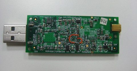
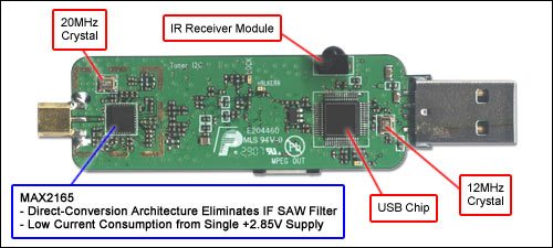 This USB reference design is for handheld digital video broadcast (DVB-H) applications on computers, laptops and other portable/handheld devices. The design is built around a MAX2165 direct-conversion tuner IC designed for digital video broadcast applications. The tuner covers a 470MHz to 780MHz input frequency range. It helps to reduce overall BOM cost and comes in a tiny package. The MAX2165 allows a programmable channel-selection allowing for operation with 7MHz and 8MHz channels. Other components used in the design are a DMB-TH demodulator and USB interface. The DMB-TH demodulator accepts inputs from the tuner and provides a MPEG-2 stream to the USB chip. The USB chip enables interfacing with a laptop or desktop for viewing broadcast video and for lab analysis .
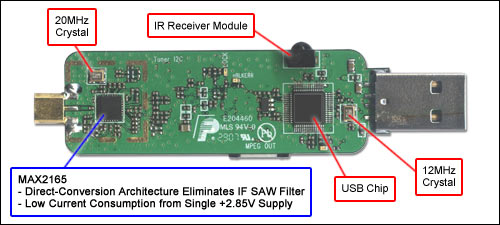
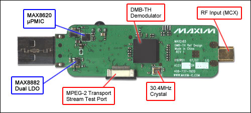

.jpg)


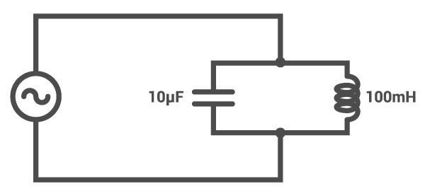


 . The reflect coefficient of the load is defined as
  . Z0 is the characteristic impedance which is normally 50 Ω.
 . Similarly, both the power source and the two-port network can be looked as the equivalent power source. The reflect coefficient of the equivalent load is defined as
  , where
  is the rated power wave of the equivalent power source.
 bS is always a constant for a given power source, so PS is determined by r1 and rS. Obviously, the maximum value of PS can be achieved only when it satisfies the following condition.
 where,
  is called as ‘power matching’ of the 1-1′ port.
 The maximum value of PL can be achieved only when it satisfies the following condition.
 where,
  is called as ‘power matching’ of the 2-2′ port.
 Here G is called as the systemic power transmission efficiency (SPTE) and its physical meaning is to measure the usage ratio of the maximum power output of the power source, namely the end-to-end system efficiency. Obviously, PL will also be the maximum when G reaches the maximum value. Interestingly,
  when rS = rL = 0, which is the same as that in Ref.[10, 11].
 and the reflect coefficient of the load is changed from rL to
  in Fig. 5. Furthermore, we will have
 By setting
  and
and  , we can get
 where,
  ,
,  ,
,  ,
,  .
.


![{\begin{aligned}{\dot x}&=-{\frac {1}{RC}}x+{\frac {1}{RC}}A_{1}A_{2}\sin(\theta _{1}(t))\cos(\theta _{2}(t)),\\[6pt]{\dot \theta }_{2}&=\omega _{{free}}+g_{v}(c^{{*}}x)\end{aligned}}](https://wikimedia.org/api/rest_v1/media/math/render/svg/ecec1d8fb087d9a53a66d39cf14f8d2480c7a666)

![{\begin{aligned}{\dot x}&=-{\frac {1}{RC}}x+{\frac {1}{RC}}{\frac {A_{1}A_{2}}{2}}\sin(\theta _{{\Delta }}),\\[6pt]{\dot \theta }_{{\Delta }}&=\omega _{{\Delta }}-g_{v}(c^{{*}}x).\end{aligned}}](https://wikimedia.org/api/rest_v1/media/math/render/svg/a27dc4e09c9f27ca06eda5c20cfd62db61852aa9)
![{\begin{aligned}x&={\frac {{\dot \theta }_{2}-\omega _{2}}{g_{v}c^{*}}}={\frac {\omega _{1}-{\dot \theta }_{{\Delta }}-\omega _{2}}{g_{v}c^{*}}},\\[6pt]{\dot x}&={\frac {{\ddot \theta }_{2}}{g_{v}c^{*}}},\\[6pt]\theta _{1}&=\omega _{1}t+\Psi ,\\[6pt]\theta _{{\Delta }}&=\theta _{1}-\theta _{2},\\[6pt]{\dot \theta }_{{\Delta }}&={\dot \theta }_{1}-{\dot \theta }_{2}=\omega _{1}-{\dot \theta }_{2},\\[6pt]&{\frac {1}{g_{v}c^{*}}}{\ddot \theta }_{{\Delta }}-{\frac {1}{g_{v}c^{*}RC}}{\dot \theta }_{{\Delta }}-{\frac {A_{1}A_{2}}{2RC}}\sin \theta _{{\Delta }}={\frac {\omega _{2}-\omega _{1}}{g_{v}c^{*}RC}}.\end{aligned}}](https://wikimedia.org/api/rest_v1/media/math/render/svg/e270e7df2f932355fbcf2a304ac607c0247b75f7)


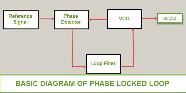
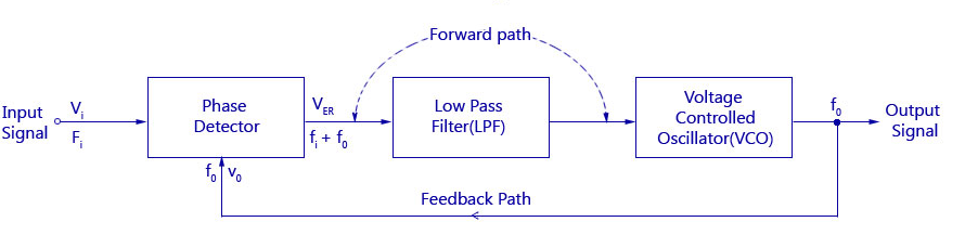
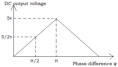
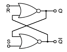
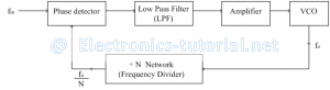
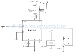
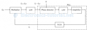
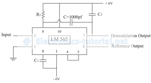
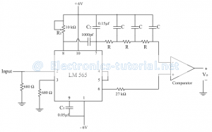
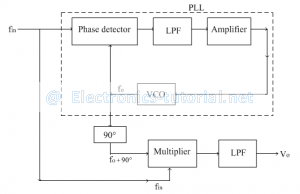


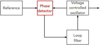


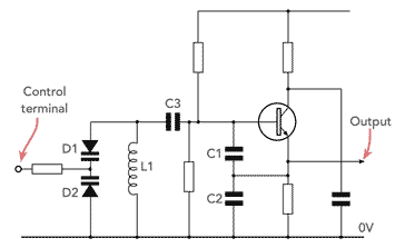


Thanks For sharing very helpful information
BalasHapusVibrating Fork Level Switch for Solids