
Satellite is a tool diagram that provides information and motion as well
e-WET (Work - Energy - Time) on ornament ornaments that are inside the earth and that are outside the earth in the form and motion of the solar system as well as observations of meteors and asteroids and the position of the nearest galaxy position that can be observed by satellite medium range imaging . when we use a satellite; our position is in the earth and outside the earth which is an automatic driver and as a power supply taken from within and outside the earth. the satellite that we see and observe is made by super power countries such as the United States (USA) or European continental countries which are now followed by the People's Republic of China. satellite moves like a moon that revolves around the earth as a constituent of seconds in our clock on earth; satellite rotates like a film roll which continuously compensates for the rotation of the earth on its axis and the sun and the contact with other star planets. although the satellite is still experiencing death and falling into the earth by the attraction of the earth --- the moon and the influence of solar radiation, a satellite will be created for a very long period of time, namely for the purpose of research and development into the planet planet region closest to existing solar energy. the satellite is currently still affected by the life force of attraction between the moon - the earth and the sun so that it still experiences a limited duty cycle life; with the possibility of someday we know the point of motion and the exact path of the satellite motion in space far away at a time when the age of the satellite will increase especially the invention of the dynamic small current technology that drives the light electronic component components on the mass point in space.
hope and love

Signature : Gen. Mac Tech
The appearance and performance of electronic equipment must be good and true performance and reliability and making a cost down .
satellite imagery and classification techniques
*.* SATELLITE COMMUNICATION
WHAT IS SATELLITE?
A Satellite is a solid object which revolves around some heavenly body due to the effect of gravitational forces which are mutual in nature. We can categorize satellites in two types, namely Passive Satellites and Active satellites. Passive satellites are not like active satellites. Even a moon can be a passive satellite. Thus passive satellites are relay stations in space. A passive satellite can be further subdivided into two types, namely Natural satellites and artificial satellites. A moon is a natural satellite of earth. But spherical balloon with metal coated plastic serve as artificial satellites.
Active satellites are complicated structures having a processing equipment called Transponder which is very vital for functioning of the satellite. These transponders serve dual purpose i.e. provides amplification of the incoming signal and performs the frequency translation of the incoming signal to avoid interference between the two signals.
All ABOUT SATELLITE COMMUNICATION
The term Satellite communication is very frequently used, but what is satellite communication? It is simply the communication of the satellite in space with large number of earth stations on the ground. Users are the ones who generate baseband signals, which is processed at the earth station and then transmitted to the satellite through dish antennas. Now the user is connected to the earth station via some telephone switch or some dedicated link. The satellite receives the uplink frequency and the transponder present inside the satellite does the processing function and frequency down conversion in order to transmit the downlink signal at different frequency. The earth station then receives the signal from the satellite through parabolic dish antenna and processes it to get back the baseband signal. This baseband signal is then transmitted to the respective user via dedicated link or other terrestrial system. Previously satellite communication system used large sized parabolic antennas with diameters around 30 meters because of the very faint and weak signals received. But nowadays satellites have become much stronger, bigger and powerful due to which antennas used have become automatically smaller in size. Thus the earth station antennas are now not large in size as the antennas used in olden days. A satellite communication system operates and works in the millimeter and microwave wave frequency bands from 1 Ghz to 50 Ghz. There are various frequency bands utilized by satellites but the most recognized of them is the uplink frequency of 6 Ghz and the downlink frequency of 4 Ghz. Actually the uplink frequency band is 5.725 to 7.075 Ghz and the actual downlink frequency band is from 3.4 to 4.8 Ghz. The major components of a Satellite Communication system is spacecraft and one or more earth earths.
THE EXCITING COMPONENTS OF SATELLITE i.e ITS SUBSYSTEMS
- Attitude & orbit control system:
This subsystem comprises of rocket motors that keeps the correct orientation of the satellite in space by moving it back to the correct orbit. Various external forces cause to change the parking position of the satellite. The primary factors are gravitational forces of sun, moon earth and also other planets of solar system. Other factors include solar pressure on the antennas and solar sails, which is present on the body of the satellite. All these factors are hugely responsible for misbalancing of the satellite and also responsible for changing the parking position of the satellite. Apart from this the earth’s magnetic field is also playing a major role in changing the parking position of satellite. The earth’s magnetic field generates eddy currents in the metallic structure of the satellite as the satellite moves through the magnetic field. Thus the body of the satellite gets rotated called as wobble of the satellite.
Remedy for Misbalancing of the satellite: station keeping: It is a method of periodically accelerating the satellite in the opposite direction against the forces acting on the body of the satellite like gravitational forces, eddy currents etc. in order to maintain the correct orientation of satellite in space and maintaining its orbit. The two most common methods employed to keep the satellite stable in orbit are: spin stabilization and three axes body stabilization.
- TTC and M SUBSYSTEMS:
These subsystems are found partly on the satellite and partly on the earth stations. Data obtained from the sensors present on the spacecraft are sent by the Telemetry systems through telemetry link to the controlling earth stations. The telemetry system monitors the condition of the spacecraft. Furthermore the Tracking system is present on the earth station which is all concerned about range, azimuth angles and elevation angles of the spacecraft by providing necessary information on it. There are various techniques used for tracking of satellite:
- Velocity and acceleration sensors on the satellite can be used to establish the change in orbit.
- Doppler shift of the telemetry carrier from the earth station or beacon transmitter may be measured to determine the rate at which the range is changing.
- Ranging tones may be used for range measurement.
- POWER SUBSYSTEM:
This is required to run satellite’s housekeeping and communication system. The block diagram of the power subsystem is shown as:
Solar panels generate direct current which is used to operate different subsystems. The batteries like Nickel-Cadmium batteries are charged by the DC power by employing the battery chargers. The stabilized low voltage is supplied to power various subsystems which are generated by the voltage regulator circuits. A dc to dc converter circuit generates high voltage dc which is used for operating the traveling wave tube amplifiers. Generation of ac from dc is done by dc to ac inverter circuits for running ac devices.
- PROPULSION SUBSYSTEM
This subsystem can also be called as a reaction control subsystem. It is carried by the satellite in the GEO orbit. The dominant functions of it are:
· It helps the spacecraft to move to its assigned position in orbit and also helps to maintain it in that position.
· It is also used to maintain the direction of spin axis attitude control against the perturbation forces.
The main components of propulsion subsystem are: Low thrust actuators, High thrust motors eg: apogee kick motor, Apogee boost motor and finally Perigee kick motor. Low thrust actuators are further classified as Chemical thrusters and Electrical thrusters. These thrusters are used for attitude and orbit corrections. Moreover the Electric thrusters are mainly of two types 1.> Plasma thrusters 2.> Ion thrusters.
- SPACECRAFT ANTENNA (subsystem)
Antenna subsystem is also an essential component of satellite system. Basically four main type of antennas are used: these are Monopoles and dipoles (wire antennas) which are mainly used in VERY HIGH FREQUENCY AND ULTRA HIGH FREQUENCY to provide communication for TTC and M subsystem. 2.> Horn antennas are mainly used at microwave frequencies. Horns are actually used as feeds for reflector. 3.> Array antennas are actually phased array antennas which are used on satellites to form multiple beams from single aperture. 4> Reflector antennas are commonly used for earth station antennas and the most widely employed shape of it is the paraboloid with a feed placed at its focus. The patterns for different satellite antennas are shown as:

- THE KEY ELECTRONIC EQUIPMENT IN A SATELLITE OR TRANSPONDERS:
It is the key electronic component in a satellite. The transmitter receiver combination in a satellite is known as a Transponder. It performs two major functions 1.> It provides amplification of the signal thus providing a gain of around 110dB. 2> It also does the frequency down conversion or frequency translation of the uplink signal in order to avoid interference between the received and the transmitted signal.
Types of Transponders: 1. Bend pipe type Transponder 2. Regenerative type Transponder.
Bend pipe type transponders are also called conventional type transponders.
Diplexer (acting as a two-way microwave gate) is the device which is responsible or used by the satellite for both receiving the uplink signal and transmitting the downlink signal. The frequency down conversion is done in the carrier processor. Amplification of the weak received signal is done in the front end. The downlink frequency is brought to a sufficient power level by amplification by the power amplifier such as Traveling Wave tube. The carrier processing equipment determines whether the transponder is of conventional or regenerative type
Regenerative Transponders: The regenerative transponder is one where there is provision for detection and demodulation process. The main advantages for these kind of transponders are:
· The signal to noise ratio is improved.
· These are simpler and more flexible to implement.
· At low baseband frequency the amplification is easier to obtain in case of regenerative type.
Types of multi channel transponder systems:
- Broadband system
- Dual channelized system.
The various frequency translation schemes in use:
FOR CONVENTIONAL TRANSPONDERS
- RF-RF Translation: This is a single mixer system. The diagrams of it is shown below:
- RF-IF-RF translation schemes: This is a double conversion scheme using a single stable oscillator. This kind of translation scheme provides two advantages over RF-RF conversion scheme: 1. The process of carrier filtering is done at the IF band. 2. Before the return transmitted signal the uplink carriers can be easily removed. The diagram of it is shown below:
FOR REGENERATIVE TRANSPONDERS
The two common schemes are:
- IF Remodulation scheme: In this technique the uplink RF spectrum is first translated down to low IF band , which is then modulated on to return RF.
- Demodulation- Remodulation scheme: The remodulation removes the uplink noise and interference from return modulation.
SATELLITE LAUNCH VEHICLES:
Satellites are launched into its orbit by the satellite launch vehicles. These satellite launch vehicles are basically multistage rockets. It is classified into two types:
- Expendable launch vehicle (ELV) eg: Ariane, Delta etc. These vehicles get destroyed in space and it also carries more than one satellite with it.
- Reusable launch vehicle (RLV). Also known as space transportation system (STV) eg: Space shuttle. In case of these satellites the vehicle will return back to the earth after leaving the satellite in space. Thus they can be reused again and again.
Components of Launch vehicle:
- Propulsion system.
- Auto piloting system
- Aerodynamic structure
- Interactive steering subsystem
DIFFERENCE OF COMMUNICATION SATELLITE FROM COMMUNICATION RELAY:
- For communication satellites the range is much higher than that of communication relay. Communication Satellite can cover up to several thousand kilometers.
- For communication satellite the uplink and the downlink frequency is the same. But for communication satellites the uplink and the downlink frequencies are different in order to avoid interference.
Different frequency bands used in satellite communication:
- Ultra high frequency band (UHF).
- C-Band.
- X-Band.
- Ku-Band
- Ka-Band.
Communication Satellites Component Diagram


Satellite communication plays a vital role in global communication where we use artificial satellites to communicate amongst various earth stations. They are used for both analogue and digital communication for carrying voice, video and data to and from various locations. In this paper, we have created a scenario where devices communicate with satellites using ANESAT protocol for different applications like FTP, FTP generic, CBR and VBR etc and analyzed the performance of the scenario in terms of throughput, total bytes sent and received from the server to the client. We have used qualnet network simulator for simulation and analysis .
I. INTRODUCTION |
| A satellite [1-4] is a physical object which revolves around a heavenly body due to its gravitational pull. It may be natural or artificial e.g. the moon is a natural satellite revolving around the Earth whereas INSAT (launched by USSR) is an artificial satellite. An artificial satellite is launched mainly to gather information about various locations on Earth and put it into use. |
|
| The basic block diagram of the satellite communication as shown above is described below: |
| The user sends a request by generating baseband signals which is carried to the Earth station via a dedicated link or a Terrestrial system. Here, the signal gets processed and converted to the uplink frequency and transmitted to the Satellite by the means of dish antennae. The satellite gathers the information and converts it into a downlink frequency which is received by the Earth station through a parabolic dish antenna where it is processed into a baseband signal so as to be sent to the user. |
| A satellite communication system works at the microwave frequency range of 1GHz to 50GHz. |
| This paper is organized as follows: Section I gives the Introduction to satellite Communication. Section II is important to understand the technologies and protocols used in this paper. Section III shows the simulation structures upon which the analysis was done. Section IV shows the results of the simulation of the scenarios using FTP, FTP Generic, CBR and VBR. Section V gives the conclusion to the analysis. Section VI gives the list of references which helped us to proceed in our paper. |
II. OVERVIEW |
| A. Abstract Network Equation – Satellite (ANESAT) Model |
| A system [5] consists of a singular or plural subnets operating across a bidirectional set of channels. Each subnet has a single downstream or forward link and a number of upstream links. Each downstream link working on TDMA is based on the priority dequeuing from the Network layer. Each subnet has a satellite or a ground station as a head-end and multiple client terminals. The head-end controls the usage of the upstream and downstream channels. Each upstream contains a shared set of data which may be grouped if two or more subnets wish to share their channels. A traffic conditioner is also used to limit the amount of traffic being transmitted regardless of the available rate. This traffic conditioner is connected to all nodes in the subnet. The network layer processes the information packets at all terminals. Additional queuing disciplines such as Strict Priority Queuing and Weighted Fair Queuing may be imposed at the client terminal model. Implemented Features in it are: |
| Both bent-pipe and processing payload functionality. |
| An advanced DAMA for the satellite models |
| 80x speed up on models |
| A high performance scheduler for QualNet |
| B. 802.11b Technology |
| 802.11b technology is an IEEE standard for wireless LAN networks (WIFI networks) which uses a 2.4GHz radio frequency range. Using this technology a router is able to send radio signals to other computers/electronic devices. The other devices must have a WIFI card with the ability to send and receive 802.11b signals. |
| Its features include: |
| Speed: It can transfer data at a rate of almost 11Mbps. |
| Range: Extends over 50m (150 feet). However range can vary depending on the structure of buildings. |
| Clarity: Since it operates at a comparatively lower frequency, the signals are clear and can even move through walls and other obstacles. |
| Price: The network can be setup at a reasonable cost. |
| Interference: The signals can interfere with frequencies of other home appliances cordless telephones, microwave ovens, garage door openers, and baby monitors which is regarded as a disadvantage of this technology. |
| Better upcoming technologies: Although comparable to traditional Ethernet (10 Mbps), it performs significantly slower than newer Wi-Fi and Ethernet technologies including 802.11g and Fast Ethernet. |
| C. File Transfer Protocol |
| File Transfer Protocol (FTP) is a standard Internet protocol for transmitting files between computers on the Internet. FTP is commonly used to transfer Web page files from their creator to the computer that acts as their server for everyone on the Internet. It's also commonly used to download programs and other files to your computer from other servers. FTP is built on a clientserver architecture and uses separate control and data connections between the client and the server. FTP users may authenticate themselves using a clear-text sign-in protocol, normally in the form of a username and password, but can connect anonymously if the server is configured to allow it. FTP support is usually provided as part of a suite of programs that come with TCP/IP. |
| The first FTP client applications were interactive command-line tools, implementing standard commands and syntax. Graphical user interfaces have since been developed for many of the popular desktop operating systems in use today, including general web design programs like Microsoft Expression Web, and specialist FTP clients such as CuteFTP. |
| D. Constant Bit Rate |
| Constant Bit Rate is an encoding method where the bitrate used doesn't fluctuate. It means that the rate at which a codec's output data should be consumed is constant. CBR is useful for streaming multimedia content on limited capacity channels since it is the maximum bit rate that matters, not the average, so CBR would be used to take advantage of all of the capacity. CBR would not be the optimal choice for storage as it would not allocate enough data for complex sections (resulting in degraded quality) while wasting data on simple sections. CBR processes audio faster than VBR due to its fixed bit rate value. The downside to a fixed bit rate is that the files that are produced are not as optimized for quality vs. storage as VBR. For example, if there is a quiet section in a music track that doesn’t require the full bit rate to produce good quality sound then CBR still uses the same value - thus wasting storage space. The same is true for a complex sounds; if the bit rate is too low then quality will suffer. |
| Most coding schemes such as Huffman coding produce variable-length codes which make perfect CBR difficult to achieve. This is partly solved by varying the quantization and fully solved by the use of padding. (However, CBR is implied in a simple scheme like reducing all 16-bit audio samples to 8 bits.) |
| E. Variable Bit Rate |
| Variable Bit Rate is an encoding method in which the bit rate changes continuously during the encoding process depending on the nature of the audio. VBR files vary the amount of output data per time segment. It is designed to achieve a better sound quality vs. file size ratio than CBR (Constant Bit Rate) encoding. For example, if there is silence to be encoded then the bit rate is lowered to optimize the file size. In contrast, if the audio to be played contains a complex mix of frequencies then the bit rate is increased to give good sound quality. |
| It allows a higher bitrate (and therefore more storage space) to be allocated to the more complex segments of media files while less space is allocated to less complex segments. Using the VBR encoding method will produce an audio file that will have variable bit rates from 128Kbps to 320Kbps depending on the complexity of the audio frequencies. |
| MP3, WMA and AAC audio files can optionally be encoded in VBR. Variable bit rate encoding is also commonly used on MPEG-2 video, Xvid, DivX, etc., MPEG-4 Part 10/H.264 video, Dirac and other video compression formats. |
III. SENARIO DESIGNED |
| We have designed a scenario for inter satellite communication network consisting of 30 users or base stations under 2 satellites. There is a wireless link between base stations and satellite we have a wired link between two satellite for ensuring reliability and security as wired connection have better performance in this respect as compared to wireless media to stimulate lossless environment in free space. The application that is running between nodes is File Transfer Protocol (Figure 2), File Transfer Protocol Generic (Figure 3), Constant Bit Rate (Figure 4) and Variable Bit Rate (Figure 5). The Throughput is analyzed for each application for ANESAT [5] protocol to know how it performs for these applications in a given scenario and environment figure 2-5 show various scenarios designed. |
 |
 |
IV. EXPERIMENTAL RESULTS |
| A. FTP |
 |
 |
V. CONCLUSION |
We have created a scenario where devices communicate with satellites using ANESAT protocol for different applications like FTP, FTP generic, CBR and VBR etc and analyzed the performance of the scenario in terms of throughput, total bytes sent and received from the server to the client. On analyzing the results obtained the performance of the system is better for FTP then FTP generic then for CBR and least for VBR on basis of bytes received and overall throughput. We have analyzed ANESAT protocol for satellite communication for various applications like FTP, FTP generic, CBR, VBR on basis of throughput and bytes received in future we can compare the performance of other satellite protocols for some other applications also. |

Satellite Constellation Diagram

Transponder Satellite Block Diagram

Modelling and Controling a Satellite Tracking System
This was a modelling and simulation of the control system, no hardware was implemented.Using a Control Theory standpoint, a discrete controller was designed to meet the following specifications:
2. Assume an open-loop system, i.e., disconnect the feedback path, and do the following: (1) predict the open-loop angular velocity response of the system to a step voltage at the input of the power amplifier and (2) find the damping ratio and natural frequency of the open-loop system.
3. Given the block diagram of the antenna azimuth position control system with GC(z)=K, i.e., a discrete proportional controller: (1) derive a transfer function for the closed-loop system and calculate the system response to a unit step input, (2) find the stable range of gain K, (3) if possible, calculate the peak time, percent overshoot, rise time and settling time for the closedloop system as a function of K, (4) find the value of K that yields a 10% overshoot to a unit step input, (5) find the steady-state error Ess, in terms of the gain K, for step and ramp inputs, and (6) find the value of gain K which yields a 5% steady state error to a unit step or ramp, as appropriate. If these tasks are not possible for the specified sampling rate, determine a new sampling rate that can satisfy the desired performance specifications.
4. Given the block diagram of the antenna azimuth position control system, specify a discrete compensator GC(z) such that the closed loop system approximately meets the following: (1) 4% overshoot to a unit step input, (2) a settling time of 5 seconds, and (3) a steady state error of 1% to a unit ramp input. Note, you may use any form of compensation desired for GC(z), i.e., PID controller, lead-lag controller, observer-based, etc. Perform a robustness analysis on your design, i.e., provide a through analysis on how system disturbances, e.g., noise, or changes in the system parameters, control parameters and/or sampling period affect your closed-loop system performance. Provide evidence where possible, e.g., a mathematical analysis, Matlab plot, etc.
We were tasked to model, design, and simulate a discrete control system that meets customer specifications for a satellite antenna currently available on the market and suggest ways of improving system performance from either a controls engineering standpoint for a mechanical design standpoint.
Although the initial plan of the class was to have time alloted to allowing our group to build the system to a model scale, due to time constraints, this portion was not assigned.
 The block diagram before adding controller |  The schematic of the system without controller | Layout of entire system before controller |
XO__XO Satellite Information
There are many satellites in orbit fulfilling a huge variety of functions. Satellite technology has now become a part of everyday life, enabling worldwide communications, global navigation, surveying and monitor as well as gathering data for weather forecasting, and many more applications.
There are many facts associated with satellites that are both interesting and useful. Often the facts about these satellites and satellites in general may not be obvious.
We have compiled a page of interesting satellite facts as an introduction to satellite technology.
Please read some of our other satellite pages to gain more of an insight into satellite technology in general.
Facts about numbers of satellites in orbit
| FACT | DETAILS |
|---|---|
| Number of satellites | Over 2 500 in orbit around the Earth |
| First rockets that entered outer space | The German V2 rocket in mid 1940s |
| Number of man-made objects orbiting the Earth | In excess of 10 000 |
Facts about satellite firsts
| FACT | DETAILS |
|---|---|
| First fictional depiction of satellite | The first mention of the idea of a satellite in a fictionals tory occurred in a short story by Edward Everett Hale, The Brick Moon. This story appeared in a publications entitled" The Atlantic Monthly". The serialisation started in 1869 |
| First treatise on the use of satellites | The idea of a satellite was first postulated Konstantin Tsiolkovsky (1857-1935). In 1903 he published an academic paper entitled: " Means of Reaction Devices." In this he proposed the idea of a multi-stage rocket using liquid hydrogen and oxygen being used to launch the satellite into orbit as well as calculating the orbital speed required to maintain orbit as 8 km/s. |
| First concept of a space station | This occurred in 1928 when the Slovenian scientist, Herman Potocnik (1892-1929) published a book entitled: "The Problem of Space Travel - The Rocket Motor." In this he devised a scheme for establishing a permanent human presence in space. He developed the concept for the space station in some detail and calculated its geostationary orbit. He then went on to describe the use of orbiting spacecraft for observation of the ground for both commercial and military applications. |
| First detailed concept of geostationary communications satellites | This appeared in an article in 1945 in a British magazine entitled Wireless World. Although written by the famous English science fiction writer Arthur C. Clarke (1917-2008) it postulated the concept of communications satellites to be used for mass communications. Clarke investigated many aspects of the system from the satellite launch, possible orbits and other aspects of the creation of a network of world-circling satellites. He also correctly suggested that just three geostationary satellites would provide coverage over the entire planet. Unfortunately he did not realise quite how much the system would be used, and that many more satellites would be required to cater for the huge volume of data. |
| First satellites | Sputnik 1 was launched by the Soviet Union on 4th October 1957. It was a football sized globe that transmitted a "beep beep" sound as it orbited the Earth. The word Sputnik means satellite. It continued transmitting for about 21 days. |
| Second satellite | Explorer 1 launched 31st January 1958 by USA. |
| First passive reflector satellite | Echo 1 - launched by the USA on 12 August 1960. It was used as a large reflector for radio signals, and was also plainly visible from Earth to the naked eye |
| First active repeater communications satellite | Courier 1B - this was launched on 4 October 1960. It was also the first satellite powered by solar cells that were used to re-charge batteries used to power the system when behind the earth. |
| First direct relay communications satellite | Telstar 1 - launched on 10 July 1962, it carried the first transatlantic live television pictures via satellite. It was also used for telephone and high speed data communications. |
| First communications satellite in geostationary orbit | Syncom 2. This was launched on 19 August 1964. It carried the first Olympic broadcasts to international audiences via satellite. These Olympics were held in Tokyo. |
| Read more about Communications satellites | |

Image courtesy NASA
Facts about satellite orbits
| FACT | DETAILS |
|---|---|
| Geostationary orbit | An orbit in which the satellite has the same angular velocity as the Earth so it appears above the same position above the Earth at all times. These orbits can only be directly above the equator. |
| Geostationary orbit altitude | Approximately 35 786 km, 22 236 mile |
| Geostationary orbital velocity | Approximately 3.07 km/s, 1.91 miles/s |
| Geostationary orbital period | 1 sidereal day, 23.934461223 hours, 23 hours 56 minutes and 4 seconds, 1 436 minutes 4 seconds. |
| Geostationary orbit distance | The distance around the path of a complete geostationary orbit is approximately 265 000 km or 165 000 miles |
| Low Earth Orbit, LEO altitude range | 200 - 1200 km |
| Medium Earth Orbit, MEO altitude range | 1200 - 35790 km |
| High Earth Orbit, HEO altitudes | Above 35790 km |
| Read more about Satellite orbits | |
Facts about the satellite navigation
| FACT | DETAILS |
|---|---|
| Most widely used SatNav | GPS - Global Position System |
| GPS official Name | Navstar |
| GPS operator | US Department of Defense |
| Navstar constellation | 24 satellites + orbiting spares |
| Navstar satellite expected life-time | 10 years |
| Navstar typical size | Dependent upon the satellite series and build date, but typically 17 feet across with antennas extended |
| Navstar typical weight | Dependent upon the satellite series and build date, but can be around 1860 pounds. |
| Navstar transmit power | ~ 50 watts |
| Navstar solar panel capability | Solar panels generate about 700 watts of electricity |
| Navstar orbits | The satellites are in one of six orbits. These are in planes that are inclined at approximately 55 degrees to the equatorial plane and there are four satellites in each orbit. The orbits that are roughly 20200 km above the surface of the Earth. |
| Navstar satellite speed | Approximately 14000 km / hour, 8500 mph |
| Navstar orbit time | Approximately 12 hours |
| Read more about Global Positioning System, GPS | |
Direct broadcast satellite facts
| FACT | DETAILS |
|---|---|
| Name | Although commonly called Direct Broadcast Satellite, DBS, it is officially known by the International Telecommunication Union, ITU, as Broadcasting Satellite Service, or BS. It is a direct to home, DTH service |
| Frequency bands |
|
Satellites are able fulfil a number of roles. One of the major roles is for satellite communications. Here the satellite enables communications to be established over large distances - well beyond the line of sight. Communications satellites may be used for many applications including relaying telephone calls, providing communications to remote areas of the Earth, providing satellite communications to ships, aircraft and other mobile vehicles, and there are many more ways in which communications satellites can be used.
Communications satellite advantages & disadvantages
Satellites are able to provide communications in many instances where other forms of communications technology may not provide a feasible alternative.
Communications satellites provide a number of advantages
- Flexibility: Satellite systems are able to provide communications in a variety of ways without the need to install nw fixed assets.
- Mobility: Satellite communications are able to reach all areas of the globe dependent upon the type of satellite system in use, and the ground stations do not need to be in any one given location. For this reason, many ships use satellite communications.
- Speedy deployment: Deployment of a satellite communications system can be very speedy. No ground infrastructure may be required as terrestrial lines, or wireless base stations are not needed. Therefore many remote areas, satellite communications systems provide an ideal solution.
- Provides coverage over the globe: Dependent upon the type of satellite communications system, and the orbits used, it is possible to provide complete global coverage. As a result, satellite communications systems are sued for providing communications capabilities in many remote areas where other technologies would not be viable..
When considering the use of a satellite some disadvantages also need to be taken into consideration.
- Cost: Satellites are not cheap to build, place in orbit and then maintain. This means that the operational costs are high, and therefore the cost of renting or buying space on the satellite will also not be cheap.
- Propagation delay: As distances are very much greater than those involved with terrestrial systems, propagation delay can be an issue, especially for satellites using geostationary orbits. Here the round trip from the ground to the satellite and back can be of the order of a quarter of a second.
- Specialised satellite terminals required: Even though the operator will operate all the required infrastructure, the user will still need a specialised terminal that will communicate with the satellite. This is likely to be reasonably costly, and it will only be able to be used with one provider.
Telecommunications satellite links
Communications satellites are ideally placed to provide telecommunications links between different places across the globe. Traditional telecommunications links used direct "cables" linking different areas. As a result of the cost of installation and maintenance of these cables, satellites were seen as an ideal alternative. While still expensive to put in place, they provided a high bandwidth and were able to operate for many years.
In recent years the bandwidth that can be offered by cables has increased considerably, and this has negated some of the gains of satellites. Additionally the geostationary satellites used for telecommunications links introduce a significant time delay in view of the very large distances involved. This can be a problem for normal telephone calls.
However satellite communications systems provide significant levels of flexibility and mobility provide the opportunities for many satellite communications systems. Although the initial infrastructure costs are high, often new remote stations can be added relatively cheaply as new lines do not need to be installed to provide communication to the new remote station, unlike wire based telecommunications systems or many terrestrial wireless links were repeater stations may be needed.
Communications satellite applications
There are many different ways in which communications satellites can be used:
- Telecommunications: Satellite systems have been able to provide data communications links over large distances. They were often used in place of intercontinental submarine cables which were expensive and unreliable in their early days. Nowadays cable technology has significantly improved to provide much higher levels of capacity especially as a result of fibre optic technology and their reliability has also greatly improved. As a result satellites are less frequently used to replace terrestrial cables, although in some instances this remains the case.
- Satellite phones: The concept of using a mobile phone from anywhere on the globe is one that has many applications. Although the terrestrial cellular network is widely available, there are still very many areas where coverage is not available. In these situations satellite phones are of great use.
As an example satellite phones are widely used by the emergency services for situations when they are in remote areas, even of countries that might have a good cellular network, but not in remote areas. They may also be for communications in rural areas where no cellular coverage may be available. They also find uses at sea, and in developing countries, or in uninhabited areas of the globe. - Direct broadcast : While terrestrial broadcasting is well established it has a number of limitations: namely the coverage, especially in hilly areas where the hills may shade the signals from receivers, and also the bandwidth which is prime spectrum in the lower end of the UHF portion of the spectrum.
Direct broadcast satellite, DBS, technology enables both these issues to be overcome. The high angle of the satellites means that for most latitudes a high angle of signal direction means that hills do not provide a major coverage issue. Also operating around 12 GHz, more bandwidth is generally available enabling more stations - both television and radio - to be accommodated.
Satellite communications summary
Although the basics of satellite communications are fairly straightforward, there is a huge investment required in building the satellite and launching it into orbit. Nevertheless many communications satellites exist in orbit around the globe and they are widely used for a variety of applications from providing satellite telecommunications links to direct broadcasting and the use of satellite phone and individual satellite communication links.
Communications satellites are used within a variety of different applications.
These range from large scale telecommunications satellites sued for maintaining data links over large distances, to those used for smaller scale communications applications
Communications satellite subsystems
Communications satellites comprise a number of elements. Typically they incorporate the following main elements:
- Communication Payload: This could be considered to be the main element of the communications satellite. It consists of transponders, antenna, and switching systems
- Engines: These are used to bring the satellite to its required
- Station Keeping Tracking: This subsystem incorporates a stabilisation system and small propulsion system to maintain the orientation and correct orbit during the operational life of the satellite.
- Power subsystem: The power subsystem of the communications satellite is used to power the satellite systems. It normally contains two elements:
- Solar cells: These are used to provide power when the satellite is in sunlight. These normally consist of large arrays of solar cells often on extended arms. Some satellites may just be covered in solar cells to reduce the overall footprint of the satellite.
- Batteries: Batteries are required to power the satellite when it is in an area of darkness such as when it passes the dark side of the earth, or during solar eclipses.
- Command & Control: This sub-system maintains communications with ground control stations. The ground earth stations continually monitor the satellite state and health and control its functionality. This will vary over different phases of its life-cycle. At end of life it may be necessary to place the satellite into a different orbit, or even send it into outer space where it will not clutter the orbit.
Satellite communications basics
When used for communications, a satellite acts as a repeater. Its height above the Earth means that signals can be transmitted over distances that are very much greater than the line of sight. An earth station transmits the signal up to the satellite. This is called the up-link and is transmitted on one frequency. The satellite receives the signal and retransmits it on what is termed the down link which is on another frequency.

The circuitry in the satellite that acts as the receiver, frequency changer, and transmitter is called a transponder. This basically consists of a low noise amplifier, a frequency changer consisting a mixer and local oscillator, and then a high power amplifier. The filter on the input is used to make sure that any out of band signals such as the transponder output are reduced to acceptable levels so that the amplifier is not overloaded. Similarly the output from the amplifiers is filtered to make sure that spurious signals are reduced to acceptable levels. Figures used in here are the same as those mentioned earlier, and are only given as an example. The signal is received and amplified to a suitable level. It is then applied to the mixer to change the frequency in the same way that occurs in a superheterodyne radio receiver. As a result the communications satellite receives in one band of frequencies and transmits in another.
In view of the fact that the receiver and transmitter are operating at the same time and in close proximity, care has to be taken in the design of the satellite that the transmitter does not interfere with the receiver. This might result from spurious signals arising from the transmitter, or the receiver may become de-sensitised by the strong signal being received from the transmitter. The filters already mentioned are used to reduce these effects.

Block diagram of a basic satellite transponder
Signals transmitted to satellites usually consist of a large number of signals multiplexed onto a main transmission. In this way one transmission from the ground can carry a large number of telephone circuits or even a number of television signals. This approach is operationally far more effective than having a large number of individual transmitters.
Obviously one satellite will be unable to carry all the traffic across the Atlantic. Further capacity can be achieved using several satellites on different bands, or by physically separating them apart from one another. In this way the beamwidth of the antenna can be used to distinguish between different satellites. Normally antennas with very high gains are used, and these have very narrow beamwidths, allowing satellites to be separated by just a few degrees.

Separating satellites by position
Satellite communications channel characteristics
Satellite communications links need to be designed to enable the inherent link characteristics to be accommodated:
- Propagation delay - latency: In view of the altitude of many satellites - those in geostationary orbit - there are significant propagation delays. This can affect signalling and extended timeout windows may be required to accommodate the latency of the system.
- Limited bandwidth: Bandwidth is an issue for all users of the radio spectrum. Some satellites are affected more than others. Accordingly many systems will require to use the available bandwidth very effectively. Data compression schemes are normally used.
- Noise: The path length and the fact that power levels are limited, especially on the satellite means that signals do not operate with a large margins. To overcome this, directive antennas are normally employed. However in addition to this robust error correction techniques are normally required for data transmission.
With the success of mobile phone systems it was believed that satellite phone systems and satellite technology would be able to provide phone access in areas of the world that were not at that time accessible to terrestrial mobile phone systems. As a result satellite based phone systems were conceived and have been set up. The three satellite systems were Iridium, Globalstar and Iridium. Satellites for the three systems were launched and they entered service in the mid to late 1990s.
Although the satellite phone systems have been proven technically, satellite phone technology has not taken off as originally conceived. The take up of mobile phone systems was more rapid than originally expected and their coverage is greater. Nevertheless satellite phones and satellite phone systems are in use and provide essential communications in several applications.
Satellite phone basics
When devising a satellite phone system there are a number of technical challenges that need to be addressed. The path length between the earth and the satellite introduces significant losses, much greater than those encountered with terrestrial systems. It is for this reason that most of the systems use low Earth orbiting satellite systems. Geostationary satellites are usually considered too high and result in much greater levels of path loss.
Additionally the fact that the satellites are moving (in most systems) means that signals are Doppler shifted, and the technology needs to take account of this.
With the satellites in a low Earth orbit and moving across the sky each satellite will be in view for a certain amount of time. It is therefore necessary even for a stationary phone to be able to handover from one satellite to another.
Phones used for satellites are often larger in size than those used for terrestrial applications. The antenna is often larger to provide to ensure the required level of efficiency. This naturally impacts on the size of the satellite phone.
A further challenge for satellite phones arises from what are termed the backhaul communications and protocol exchanges. Any mobile phone requires to quickly communicate with the network to enable calls to be set up, controlled and finished. In view of the altitudes of the satellites the round trip delay from the mobile to the satellite and back to the earth station are too long to enable rapid communications and exchanges to take place. As a result, much of the intelligence of the system has to be placed within the satellite so that the required protocol exchanges can take place rapidly.
Satellite phone systems
Three of the major satellite phone systems that are in use are Iridium, Globalstar and Thuraya. These satellite systems adopt different approaches in many areas of the technology used.
- Iridium: The Iridium satellite system uses a total of 66 satellites orbiting in a low Earth orbit with an altitude of around 485 miles. This gives an orbiting time of around 100 minutes. Further satellites are placed in orbit to enable them to quickly replace any that fail. The satellites are in polar orbits, i.e. orbiting from pole to pole, in what is termed a 'Walker Star' configuration. For most instances the satellites in the adjacent orbit are orbiting in the same direction, there is what is termed one 'seam' where the satellites in the next orbit are orbiting in the opposite direction. This gives some problems in terms of handover and communication between these satellites.
The satellites are able to communicate with the ground as well as neighbouring satellites when they use inter-satellite links. This aids the handovers as satellites pass over and out of range. No handovers are made across a seam as the fact that satellites are contra-rotating would mean that Doppler shifts are too large and handovers would need to be made too quickly.
The Iridium system uses four Earth stations. To provide the additional paths thata re needed, space-based backhaul routes are used to send the phone call packets through space to one of the downlinks known as feeder links. These down links are required because onlly a few satellites are within view of an Earth station at any given time. These downlinks are primarily used for calls that need to be routed into the terrestrial phone system. For satellite phone to satellite phone calls, it is possible to route the traffic directly through space with no downlink. Although the satellite to satellite routing and the associated downlinks add a considerable degree of complexity to the Iridium system, it does enable fewer earth stations to be required, and it also enables full global coverage to be provided. - Globalstar: The Globalstar satellite phone system adopts a slightly different approach to that used by Iridium and this considerably reduces the complexity and hence the set up and running costs. The system uses a total of 48 satellites in orbits having an inclination of 52 degrees and 1414 kilometres or 878 miles above the Earth's surface. With this orbit it takes just less than two hours for an orbit.
Connectivity is provided only by the network of ground stations. Unlike Iridium, the Globalstar satellite phone system does not support inter-satellite linking. This also means that coverage is not worldwide as there are areas where there are no ground stations. These areas are generally over the oceans and in remote areas of the globe where it is not possible or practicable to set up ground stations.
The air interface used for Globastar uses CDMA to provide access for multiple users. Additionally handsets use elements of GSM cell phone system to provide greater functionality than offered by cdmaOne / CDMA2000. One of the key elements is the use of SIM cards. Numbers for Globastar phones use the North American '1' prefix for the country code. - Thuraya: The Thuraya satellite phone system is again different to the other two systems. It is only regional, with operations based in United Arab Emirates and it provides coverage for areas within Africa, Europe the Middle East. To achieve this it utilises a single geostationary satellite and it provides service through a network of service providers.
Thuraya handsets are cannot be used with other networks and are therefore specialised. They feature dual mode operation, operating not only via a satellite, but they can also connect to GSM 900 networks.
Summary
Satellite phones and satellite phone systems are used in a number of applications and the satellite phone sales are still strong despite the fact that they have not developed in the way that was originally anticipated. With cellular technology becoming more widespread, and this occurring more quickly than originally anticipated, the mass market that was envisaged for satellite phones did not emerge. In many cases the satellite phone systems and their owners have experienced financial difficulties, but today these satellite phone systems fulfil more specialised roles and as a result of this the sales are still strong.
Iridium satellite system is used to provide voice and data coverage to satellite phones, pagers and other equipment with full global coverage (including the poles). The Iridium satellite system is owned by Iridium LLC based in the USA. This corporation not only operates the satellite constellation, but also provides equipment and services.
The system was originally aimed at providing a global satellite phone system, in the days when terrestrial cellular based systems were not as widely used. However the speed at which cellular telecommunications systems were deployed meant that Iridium is now used for more specialised applications.
Iridium satellite system basics
The Iridium satellite system consists of a constellation of 66 satellites which are arranged in six planes. There are eleven satellites in each orbit which is a near circular orbit inclined, each one being inclined at 86.4°. These orbits provide full global coverage, including the polar areas which are not covered by satellites in geostationary orbits.,/p>
The Iridium satellite system uses a frequency band in L band 1616 - 1626.5 MHz for communication with the users. The phone systems communicate directly with the satellite which then routes the data accordingly. The data may then be routed to other satellites or to the ground.
The data may be routed directly to the ground network from the satellite. The ground network comprises two major elements:
- System control segment (which supplies the operational support and control of the constellation as well as providing tracking data to the gateways and messaging control).
- Telephony gateways (used to provide connectivity with the terrestrial PSTN system. Gateways also provide local management functionality).
The system control segment has three main constituents:
- Four telemetry tracking and command and control stations (TTAC).
- Satellite operation network centre (SNOC).
- Operational support network.
In addition to the direct links to the ground, each Iridium satellite is linked to four other satellites in the constellation. It links to two other satellites in the same orbit - these will be the ones either side of it, and it also links to two other satellites in adjacent orbits. These links provide a network in space which allows data to be routed between satellites without having to return to the ground from each satellite. Messages may even be routed across several satellites before reaching the ground. This provides a number of advantages:
- It provides a robust network that can still operate even if a ground station becomes non-operational.
- It enables a network to be run with stations placed in available regions - a particular advantage as it is not possible to set up stations in all areas for geographic reasons (polar, oceanic, etc) or for political reasons.
- It allows the network to be run with fewer ground stations - this allows costs to be reduced as manned ground stations can be expensive.
Iridium frequency bands and channels
The Iridium satellite system uses L band transponders to communicate with the ground based users with frequencies in the band 1616 - 1626.5 MHz while the backhaul to the terrestrial gateways is in the band between 29.1 and 29.3 GHz for the up-link and in the band between 19.1 and 19.6 GHz for the downlink. Links for the inter-satellite links to are in the frequency band between 22.55 and 23.55 GHz.
The user-satellite link uses a total of 10.5 MHz starting at 1616 MHz. This provides 240 channels, each separated by 41.67 kHz. This allows for a channel bandwidth of 31.5 kHz together with a suitable guard-band to accommodate inter-modulation and Doppler shifts caused by the satellite velocity relative to the ground stations.
Iridium access schemes
In order to support many users, it is necessary for the Iridium satellite system to operate a scheme where the different users can be managed so that they may gain access to the satellite system without interfering with each other. Iridium satellite technology uses both FDMA (frequency division multiple access - where users are allocated different frequencies) and TDMA (time division multiple access - where users are allocated different time slots in a transmission).
Iridium satellite summary
A tabular summary of the Iridium satellite technology is given below:
| PARAMETER | SPECIFICATION |
|---|---|
| Iridium satellite orbit | LEO |
| Orbit altitude | 780 km |
| Iridium applications | Voice and data |
| Satellites in constellation | 66 |
| User satellite link band | 1616 - 1626.5 MHz L band |
| Gateway -> Satellite up-link | 29.1 - 29.3 GHz |
| Satellite -> Gateway downlink | 19.1 - 19.6 GHz |
| Inter-satellite link | 22.55 - 23.55 GHz |
| Satellite relative velocity | 26 804 km/hr |
| Minimum angle of elevation for acceptable operation | 8.2° |
| Approximate satellite view time | 9 - 10 minutes |
| Access scheme | FDMA / TDMA |
| Frequency re-use factor | 12 |
| Total system capacity | 172 000 users |
History of Iridium satellite system
The concept of the Iridium satellite phone system arose before cellular telecommunications systems had been globally deployed in the way they are today. It was therefore anticipated that a phone system offering global coverage would be of great commercial value.
To achieve the goal, Iridium SSC was set up, with Motorola providing the technology and much of the finance. The system gained its name from the fact that originally 77 satellites were planned to orbit the Earth. This had a strong similarity to a nucleus with 77 orbiting electrons - a description that fits the element Iridium.
The satellite system was completed in may 1998, but some trails and commissioning were then required. The Iridium communications service itself was launched on 1st November 1998 with a call made by the then Vice President of the USA, AL Gore. Services were then offered to all forms of personal users and business.
Despite the successful technical launch of the system, the uptake was very much slower than anticipated. This was attributed to the fact that the deployment of cellular telecommunications systems, especially using GSM was much faster than had originally been anticipated. With roaming features, users could take their phones to many countries and make calls cheaper than they could over the Iridium system. Also there was a massive initial cost for building and launching all the satellites. Accordingly Iridium SSC entered Chapter 11 bankruptcy on 13 August 1999.
Initially no buyers were found for the company and it was anticipated that all the satellites would need to be de-orbited so that they would not be a danger when they re-entered the atmosphere. During the period that discussions about this were ongoing a set of private investors re-launched the company as Iridium Satellite LLC and they restarted the service in 2001.
The service was obviously more expensive than cellular systems and it was therefore used for specialist applications, especially in areas where no cellular coverage was available. For example rescue services, missions to remote areas of the globe, military, etc found the service useful.
With satellites becoming older, some have failed. These have been replaced with in-orbit spares. It takes some days for these replacement satellites to be moved into service, but with the number of satellites in orbit, service is only marginally degraded. Examples of replacements have occurred at various times, e.g. Iridium satellite 28 failed in July 2008 and was replaced by Iridium satellite 95.Another incident took place in 2009. At 16.56 UTC on 10 February 2009, an Iridium satellite (satellite 33) and Kosmos-2251, an out of service Russian satellite collided. Although a major collision creating large amounts of space debris, it was be replaced by a spare satellite already in orbit. This was completed during March 2009
Iridium Next
With the original constellation of satellites nearing the end of their life, Iridium announced its vision in February 2007 for the next generation of Iridium satellites. Known as Iridium Next, the new Iridium satellite system promises not only to replace the existing constellation of satellites, but Iridium Next also incorporates many new features. The basic functions for the system include:
- Backward compatibility with existing Iridium systems
- Full global coverage as before, including the polar areas not accessible to Geostationary satellites
- Low earth orbits enabling low power phones to be used.
Although it would be possible to provide a simple replacement programme for the existing Iridium satellites, it has been decided that Iridium Next will incorporate new technology to enable the system to move forward and keep up wit the enhanced requirements expected by many users today. Accordingly the new system will incorporate the following features:
- End to end IP technology
- Additional bandwidth capability to allow users more flexibility
- Incorporation of Earth imaging and other secondary payloads - thereby providing additional functionality to further utilise the satellites.
- Ability to provide data links to other space based payloads.
It is planned to replace the existing Iridium satellites so that a seamless upgrade can be effected.
Summary
The Iridium satellite system offers many advantages and is currently used by many people. This satellite phone system offers full global coverage for voice and data (albeit at a low rate). It is also certified for airborne use and along with many other roles, the Iridium satellite phone system is able provide a useful service to many.
Satellite applications
There are many applications for satellites in today's world. Ever since the first satellite, Sputnik 1, was launched in 1957, large numbers of satellites have been launched into space to meet a variety of needs. As satellite technology has developed over the years, so ahs the number of applications to which they can be put. Whatever the type of satellite it is necessary to be able to communicate with them, and in view of the large distances, the only feasible technology is radio. As such radio communication is an integral part of any satellite system, whatever its application.
Satellite applications
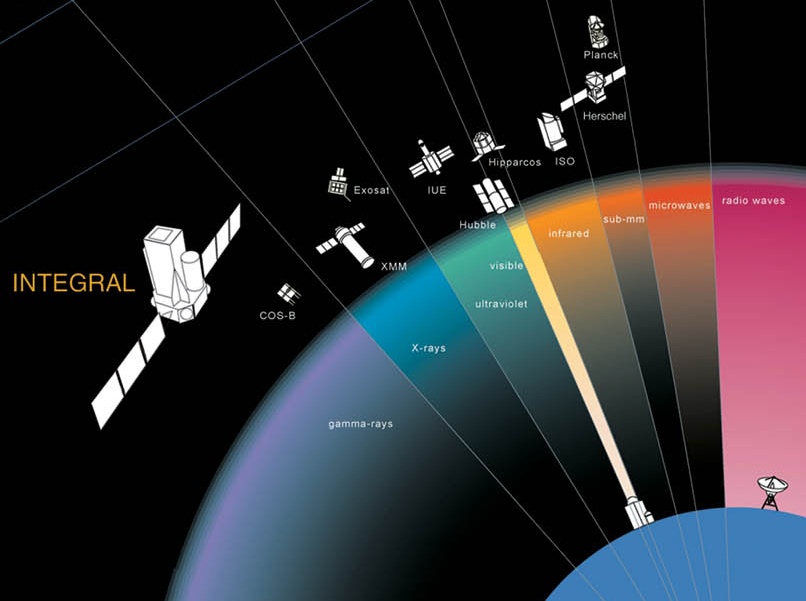
Astronomical satellites - these satellites are used for the observation of distant stars and other objects in space. Placing an observation point in space removes the unwanted effects of the atmosphere and enables far greater levels of detail to be seen than would be possible on earth where many observatories are placed on mountain tops that experience low levels of cloud. The most famous astronomical satellite is the Hubble Telescope. Although now reaching the end of its life it has enabled scientists to see many things that would otherwise not have been possible. Nevertheless it did suffer some major design setbacks that were only discovered once it was in orbit.
Communications satellites - these satellites possible form the greatest number of satellites that are in orbit. They are used for communicating over large distances. The height of the satellite above the Earth enables the satellites to communicate over vast distances, and thereby overcoming the curvature of the Earth's surface.
Even within the communications field there are a number of sub-categories. Some satellites are used for point to point telecommunications links, others are used for mobile communications, and there are those used for direct broadcast. There are even some satellites used for mobile phone style communications. Even though these satellites did not take the market in the way that was originally expected because terrestrial mobile phone networks spread faster than was originally envisaged, some mobile phone satellite systems still exist.
Even within the communications field there are a number of sub-categories. Some satellites are used for point to point telecommunications links, others are used for mobile communications, and there are those used for direct broadcast. There are even some satellites used for mobile phone style communications. Even though these satellites did not take the market in the way that was originally expected because terrestrial mobile phone networks spread faster than was originally envisaged, some mobile phone satellite systems still exist.
Earth observation satellites - these satellites are used for observing the earth's surface and as a result they are often termed geographical satellites. Using these satellites it is possible to see many features that are not obvious from the earth's surface, or even at the altitudes at which aircraft fly. Using these earth observation satellites many geographical features have become obvious and they have even been used in mineral search and exploitation.
Navigation satellites - in recent years satellites have been used for accurate navigation. The first system known as GPS (Global Positioning System) was set up by the US DoD and was primarily intended for use as a highly accurate military system. Since then it has been adopted by a huge number of commercial and private users. Small GPS systems are available at costs that are affordable by the individual and are used for car navigation, and they are even being incorporated into phones in a system known as A-GPS (Assisted GPS) to enable accurate location of the phone in case of emergency.
Further systems are planned for the future. The Russian system known as Glonass and the European and Chinese system Galileo are planned for the future.
Further systems are planned for the future. The Russian system known as Glonass and the European and Chinese system Galileo are planned for the future.
Reconnaissance satellites - these satellites, are able to see objects on the ground and are accordingly used for military purposes. As such their performance and operation is kept secret and not publicized.
Weather satellites - as the name implies these satellites are used to monitor the weather. They have helped considerably in the forecasting of the weather and have helped provide a much better understanding not only of the underlying phenomena, but also in enabling predictions to be made. A variety of these satellites are in use and include the NOAA series.
Summary
There are now many thousands of satellites in orbit around the Earth. Many are in operations, while some that have not yet fallen out of orbit are still circling the Earth. The operational satellites provide many of the services on which we rely today. Without them many of the services which we have come to accept as normal would not be so nearly to achieve by other means.
Satellite signal propagation
Satellites are used for a wide variety of applications from satellite TV broadcasting, and navigation in the case of GPS to photography, weather monitoring and many more applications. For the transmission and reception of signals, satellites normally use frequencies above 500 MHz, and often much higher. At these frequencies the transmissions to and from the satellites might be thought to be immune to the effects of the atmosphere. However this is not the case and effects are introduced primarily by two areas of the atmosphere. One is the troposphere and the other is the ionosphere. Accordingly satellite propagation or the radio propagation characteristics of the path between the ground and the satellite of great importance.
The atmosphere
The atmosphere can be divided into several areas. It is found that the temperature varies according to the height. Initially the temperature falls until altitudes of around 10 km are reached. At this point the temperature is around -50 or -60 Celsius. It is around this point that the temperature starts to rise again. The region below this inflexion point is known as the troposphere.
The second area that affects radio signals is known as the ionosphere. This is a region of the atmosphere that starts at altitudes of around 50 km, and extends to more than 400 km. In this region radiation from the Sun mainly in the form of ultraviolet light strikes the gas molecules and atoms causing them to ionise producing a positive ion and a negative electron. These electrons then affect radio signals, effectively reflecting those in the short wave bands and often returning them to Earth. However this region also affects the signals passing to and from satellites.
Beyond the ionosphere the signals can be considered to be in free space, and the region between the upper reaches of the troposphere and the ionosphere is often temred "inner free space." This region too has little effect.
There are a number of different of radio signal propagation effects that are introduced into satellite radio signals by the troposphere and ionosphere. Transmission in free space has unity refractive index and is loss-less (apart from the spreading effect that reduces the signal power over a fixed area with distance away from the source, but no power is actually lost).
The troposphere and ionosphere have refractive indices that differ from unity. The troposphere is greater than unity and the ionosphere is less than unity and as a result refraction and absorption occur. The inner free space region also has little effect.
Faraday rotation
Faraday rotation is an effect that affects satellite propagation. Faraday rotation results from the fact that the ionosphere is a magneto-ionic region. The Faraday rotation of a signal causes different elements of a signal to travel in different ways, particularly rotating the plane of polarisation. This can create some problems with reception. A linearly polarised signal can be considered as two contra-rotating circularly polarised signals. The phase velocities of these two signals vary in a magnetic medium such as the ionosphere and as a result the polarisation of the signal changes. The degree of change is dependent upon the state of the ionosphere and it follows the same pattern as that experienced for HF ionospheric communications changing over the course of the day, with the seasons and over the sunspot cycle.
Ionospheric scintillations
Another satellite propagation effect introduced by the ionosphere is termed "ionospheric scintillations." These scintillations manifest themselves as a variety of variations of amplitude, phase, and polarisation angle. They can also change the angle of arrival of the signals. These variations change over a period of between one to fifteen seconds, and they can affect signals well into the microwave region.
The variations are caused primarily by the variations in electron density arising in the E region, often as a result of sporadic E but also in the F layer where a spreading effect is the cause. The level of scintillation is dependent upon a number of factors including the location of the earth station and the state of the ionosphere, as a result of the location, the sunspot cycle, the level of geomagnetic activity, latitude, and local time of day.
The scintillations are more intense in equatorial regions, falling with increasing latitude away from the equator but then rising at high latitudes, i.e. in the auroral zone or the region where auroras take place. The effects are also found to decrease with increasing frequency, and generally not noticeable above frequencies of 1 - 2 GHz. As such they are not applicable to many direct broadcast television signals, although they may affect GPS, and some communications satellites.
Tropospheric satellite propagation effects
There are a number of satellite propagation effects that the troposphere introduces including signal bending as a result of refraction, scintillation, and attenuation.
The signal refraction in the troposphere is in the opposite sense to that in the ionosphere. This is because the refractive index in the troposphere is greater than unity, and it is also frequency independent. The signal refraction gives them a greater range than would be expected as a result of the direct geometric line of sight. Tropospheric ducting and extended range effects that are experienced by terrestrial VHF and UHF communications may also be experienced when low angles of elevation are used.
Scintillations induced by the troposphere are often greater than those seen as a result of the ionosphere. They occur as a result of the turbulence in the atmosphere where areas of differing refractive index move around as a result of the wind or convection currents. The degree to which the scintillations occur is dependent upon the angle of inclination, and above angles of around 15 degrees the effect can normally be ignored. At angles between 5 and 10 degrees the changes can often be around 6 dB at frequencies of around 5 GHz.
Doppler shift
Frequency changes as a result of the Doppler shift principle may be in evidence with signals from some satellites. This form of satellite propagation effect is important because it plays a major part in the systems design of a satellite system. The shifts resulting from the Doppler phenomenon need to be taken into account as part of the overall design.
Satellites in Low Earth Orbits move very quickly and as a result a Doppler frequency shift is apparent in many cases. With the satellite moving towards the earth station the frequency appears higher than nominal, and then as it moves away the apparent frequency falls. The degree of shift is dependent upon a number of factors including the speed of the satellite (more correctly its speed relative to the earth station) and the frequencies in use. Shifts of the order of 10 kHz may be experienced. As most satellites operate in a cross mode configuration, the Doppler shift is not just applicable to the band on which the signal is received, but to the cumulative effect of the uplink and downlink transmissions. In many instances the effects will subtract because of the way the satellite mixing process is configured.
Summary
Although satellites generally operate at frequencies that may be thought to be immune from tropospheric and ionospheric disturbance, these regions still have a significant effect and this needs to be taken into account when designing satellite systems. As a result satellite propagation, i.e. the radio signal propagation to and from the satellites of great importance.
Satellite Solar Outage or Sun Outage
One problem that can occur with satellite systems is what is termed a "Satellite Solar Outage" or "Sun Outage".
During a solar outage it may not be possible to receive the signal from the satellite, or alternatively the signal will be degraded.
Solar outages affect all satellite systems, and they are quite predictable and they arise from the basic physics behind the operation of a satellite system, and indeed any radio communications link.
Satellite solar outage basics
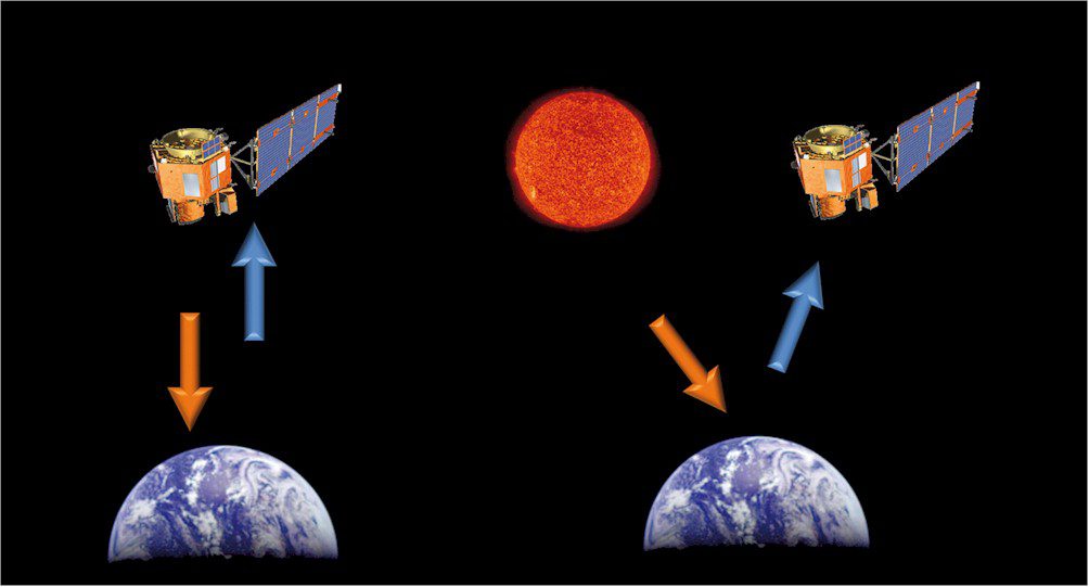
Satellite solar outages occur because the Sun which is a powerful broadband microwave noise source passes directly behind the satellite (when viewed from Earth) and the receiver with the beam directed towards the satellite picks up both the satellite signal and the noise from the Sun.
The degree of interference caused by a satellite solar outage varies from slight signal degradation to complete loss of signal as the downlink is swamped by the noise from the Sun.

Mechanics behind a solar outage
For geostationary satellites, the solar outage can typically cause disruption to the received signal for a few minutes each day for a few days. The exact date, time and duration of such events depends on a variety of factors including:
- Receiver location
- Location of the particular satellite
- Size, or more specifically the beamwidth of the antenna
- The apparent radius of the Sun as seen from the earth (about 0.25°).
- Accuracy of alignment of the antenna direction towards the satellite
Parameters such as the antenna directivity can make large differences to the amount of time of the solar outage. Antennas with a very wide beamwidth could be affected for as much as half an hour, whereas antennas with higher gain and directivity levels as are more commonly used for satellite reception will be affected for much shorter periods of time. Typically only a few minutes.
The effect of the solar noise causing the outage is very marked. Even at times of low solar activity, the effect is very noticeable and can result in noise levels of between 10 and 20 dB above the signals from transponders, dependent upon a host of factors.
Solar outage angle
It is possible to define what is termed and outage angle of the receiving antenna. The solar outage angle of the antenna angle is defined as the separation angle (measured from the ground station antenna) between the satellite and the Sun at the time when sun outage or signal degradation begins or ends.
It is not always possible to exactly predict the duration of a solar outage. The exact point at which the solar outage begins and ends is a gradual transition. In addition to this there are many differences between different installations and systems. Accordingly some stations may experience a complete loss of signal while others may only experience a tolerable degradation of signal. In view of this it is not possible to exactly determine the exact solar outage angles without complete information about the ground station equipment and the satellite parameters. However an approximation can be gained from the following equation:
| Outage angle = | 11 (Frequency) x (Diameter) | + 0.25° |
Where (Frequency) = Downlink Frequency in GHz
Where (Diameter) = Receiver parabolic reflector or dish antenna diameter in metres
Where (Diameter) = Receiver parabolic reflector or dish antenna diameter in metres
When do satellite solar outages occur
For geostationary satellites, solar outages occur around the equinoxes, i.e. March / April and then again in September / October. At these times of year the Sun crosses the equator and it traces an arc that places it directly behind geostationary satellites.
It is found that the in the Northern Hemisphere, solar outages usually occur in early March and October as a result of the geometry and relative positions of satellites and the solar transit of the Sun. In the Southern Hemisphere, outages normally occur in early September and April. The time of day varies mainly with the longitude of the satellite and receiving station, while the exact days vary mainly with the station's latitude. Stations along the equator will experience solar transit right at the equinoxes, because the satellites in geostationary orbit are located directly over them.
The exact dates and times of the solar outages are easy to predict and many calculators are available. All that is needed is a knowledge of the satellite position (sometimes just the satellite is needed as its coordinates may be held within the calculator), the position of the receiver in latitude and longitude. The beamwidth of the antenna is often needed as it will enable the time of the satellite solar outage to be determined.
Summary
While satellite solar outages, or satellite sun outages can be annoying, they are normally short lived and they are totally predictable. They affect all satellites, and in particular these solar outages are commonly experienced as a result of the widespread use of satellite direct broadcast TV reception. However all satellites are affected, whether geostationary or in other orbits, and the effects can cause short lived disruption to the radio communications.
Satellite design and construction
Satellite design and construction is a particularly specialised business. The requirements for satellites are very stringent and satellites must be capable of operating in extreme conditions whilst still maintaining the highest standards of reliability because they cannot be retrieved for maintenance or repair. Apart from the general factors relating to satellite design, the circuitry required for their operation such as the transmitters and receivers, satellites also contain a number of systems used for what is called station keeping. All of these functions, whether for performing the primary role of the satellite, or for ensuring that it reliably maintains its position and function are all important and must be included in the design of the satellite.
Satellite position maintenance
Satellites need to be kept in the correct position. Although they may be placed in exactly the correct orbit after they are launched, the variations in the Earth's gravitational field and other factors may cause them to drift out of their correct position. As a result it is necessary to reposition them periodically.
Small thrusters are used to perform this operation. Often they consist of canisters of a gas which when released with a catalyst gives a form of rocket propulsion to move the satellite back on station. Often the service life of a satellite is determined by the amount of fuel for repositioning the satellite rather than the reliability of the electronics.
The other problem with a satellite is that its attitude will change. This is of great importance because directive antennas or cameras are often used, and the satellite needs to be orientated in the correct direction for them. The basic method of gaining the correct orientation is to use the thrusters. However the attitude will change comparatively quickly. The most common method to overcome this is to use the gyroscopic effect. Sometimes a large flywheel may be made to spin inside the satellite. This can be inefficient in its use of the weight of the satellite. To overcome this other cylindrical satellites actually rotate a portion of the body, often an inner cylindrical section so that the antennas mounted on the outer section do not revolve.
Satellite power
Electrical power is also required by the satellite for its electronic circuitry and other electrical systems. Although the power requirements for some satellites may be relatively modest, this is certainly not the case for satellites such as direct broadcast (DBS) or satellite television broadcasting satellites. Although they do not transmit the same levels of power that are used for terrestrial broadcasting, they still consume considerable amounts of power.
The power is supplied by the large arrays of photo or solar cells. Some cylindrical satellites have them positioned around the outer area on the cylinder so that some part of the body is always exposed to sunlight. Others have large extending panels that are orientated to collect the maximum amount of light. Today these panels are capable of producing the many kilowatts of power required for the high power output stages used in many transponders.
Batteries are also needed for the periods when the satellite is in darkness. These need to charged by the solar cells so that when the satellite passes out of the sunlight it can still remain operational. This naturally places an additional burden on the solar cells because they need to be able to power not only the satellite itself, but also charge the batteries. This may double the power they have to supply during periods of sunlight.
Satellite antennas
The antennas used on satellites are particularly important. They are the only means through which communication can take place with the ground. For geostationary satellites directional antennas are generally used. These are used because power consumption on the satellite has to be minimised wherever possible. Directional antennas provide gain and enable the best use to be made of the available transmitted power. Additionally they enable the signals from the earth to be received with the best signal to noise ratio. In view of the long path lengths required for geostationary satellites, there is a considerable path loss and the antenna gain is used to improve the received signal strength. It also helps reduce the reception of solar and cosmic noise that would further degrade the received signal. In a geostationary orbit the earth subtends only 18 degrees of arc. Any power not falling into this area is wasted.
As a result, parabolic reflector or "dish" antennas are widely used. Horn antennas are also popular and in some cases phased arrays may be employed, especially where coverage of a specific area of the globe is required. However the use of directional antennas does mean that the orientation of the antenna is crucial, and any perturbation of the alignment of the satellite can have a major effect on its operation, both in reception and transmission.
The situation is different for low earth orbit or LEO satellites. These satellites are not in geostationary orbit and they move across the sky. Additionally they may need to be received by several users at any time and this means that they cannot use directive antennas. Additionally the earth subtends around half the celestial sphere and as a result users may be separated by angles ranging from zero to almost 180 degrees. Fortunately the satellites are much closer to the earth and path losses are very significantly less, reducing the need to high gain antennas.
Environmental
The environment in which satellites operate is particularly harsh. Combined with the need for exceedingly high levels of reliability resulting from the near impossible task of repair, this means that every detail of the design and operation under these conditions must be carefully considered.
In the first instance the temperatures range over very wide extremes. The surfaces exposed to the sun are heated by solar radiation and will rise to very high temperatures, whereas the other side that is not heated will be exceedingly cold. Only conduction will give any heating effect under these circumstances. The temperature of the whole of the satellite will also fall when it is in darkness.
There are a number of other effects that must be considered. Solar radiation itself has an effect on some materials, causing them to degrade. Notice must also be taken of meteorites. Very small ones cause the surfaces to be eroded slightly, but larger ones may penetrate the body of the satellite causing significant damage. To overcome this satellites are protected by specially designed outer layers. These consist of sheets of metal which are slightly separated giving a cushioning effect when any meteorites impact on the satellite. Cosmic particles also degrade the performance of satellites. Particularly during solar flares the increase in solar particle flow can degrade solar cells, reducing their efficiency.
Ground stations
Ground stations also need an effective antenna system. For communication with satellites in geostationary orbit the antenna remains fixed, except if there is a need to change to another satellite. Accordingly parabolic reflectors are often used. This can be seen from the number of satellite TV antennas that are in use. These are a form of parabolic reflector. This type of antenna is widely sued for example with direct broadcast satellite TV. The antennas seen on the sides of houses are almost exclusively parabolic reflectors. However it is possible to use other types such as arrays of Yagi antennas. Here they are stacked (one on top of the other) and bayed (side bay side) to give additional gain.
For some low earth orbit satellites the ground station antenna systems are designed to be able to track the satellite in azimuth and elevation. This is typically achieved by automatically tracking the satellite as it moves across the sky. This is normally achieved by taking a signal level output from the receiver. By ensuring that it is maintained at its peak level the satellite will be tracked. Many low earth orbit satellites are required for systems such as positioning or even telephone style communications. Here directional antennas are not used as the user will not want to re-orientate the antenna all the time. Instead almost non-directional antennas are used and the transmitter powers and receiver sensitivities designed to give a sufficient level of signal to noise ratio. This is the case for GPS where several satellites need to be received at the same time. Accordingly receivers are designed to accommodate the very low signal levels.
Satellite design summary
Satellites are in everyday use around the globe. Not only are functions such as GPS widely used, but so are many other forms of satellite including communications satellites, weather satellites, geophysical satellites and many forms of satellites. Without them, our lives would be very different, and we have come to rely on them. Accordingly their design must be made to be very reliable as they are not easy to repair, even if it is viable - which is normally not the case, and they operate under extremely harsh conditions. Accordingly the design of a satellite is critical. The satellite design specifications need to be totally correct, and the basic satellite design needs to take all aspects into consideration, making any satellite design project particularly exacting. However if correct, the satellite will normally be able to give many years of service and pay for the large investment in the satellite design and construction.
GPS Technology
GPS, or Global Positioning System, is also sometimes called NavStar. GPS is a satellite based global navigation satellite system, GNSS that is used to provide accurate location and time information anywhere on or near the Earth.
GPS is run and maintained by the US government, although access to it has been opened up so that it is freely available worldwide when used with suitable GPS receivers.
Typically GPS is able to provide position information to within a few metres, allowing accurate positioning to be made. It is also possible to extract timing information that enables frequencies and time to be very accurately maintained. Frequency stability performance figures of systems using GPS timing are far in better than crystal or many other accurate frequency sources.
The performance and ease of use of GPS has meant that it is now an integral part of everyday life, with many portable or car-based "satnav" systems being used, as well as many mobile phones incorporating them to enable them to provide location information superimposed on the maps from the phone or satnav.
GPS basics
The basic concept behind GPS is that signals are transmitted from the satellites in space and these are received by the receivers on or near to the surface of the earth. Using timing it is possible to determine the distance from each satellite and thereby using a process of triangulation and a knowledge of the satellite positions the position on Earth can be determined.
The satellites all send timing information so the receiver knows when the message was sent. As radio signals travel at the speed of light they take a very short but finite time to travel the distance from the satellite to the receiver. The satellites also transmit information about their positions. In this way the receiver is able to calculate the distance from the satellite to the receiver. To obtain a full fix of latitude, longitude and altitude, four or more satellites are required, and when the receiver is in the clear, more than four satellites are in view all the time. A fix of just latitude and longitude can be obtained from three satellites.

GPS satellite orbits
The fully operational GPS satellite system consists of a constellation of 24 operational satellites with a few more in orbit as spares in case of the failure of one. The GPS satellites are in one of six orbits. These are in planes that are inclined at approximately 55° to the equatorial plane and there are four satellites in each orbit. This arrangement provides the earth user with a view of between five and eight satellites at any time from any point on the Earth.
Using economic ground based receivers GPS is able to provide position information to within a number of metres. The economic costs have also meant that it is now fitted to many motor vehicles, while separate GPS receivers can be bought for a few hundred pounds or dollars. As a result it is widely used by private individuals, as well as many commercial and professional users. In fact the primary use for GPS is as a military navigation system. The fact that it is used so widely is a by-product of its success.
GPS satellites
The satellites are orbiting above the Earth. Their orbits are tightly controlled because errors in their orbit will translate to errors in the final positions. The time signals are also tightly controlled. The satellites contain an atomic clock so that the time signals they transmit are very accurate. Even so these clocks will drift slightly and to overcome this, signals from Earth stations are used to correct this.
The GPS satellites themselves have a design life of ten years, but to ensure that there are no holes in service in the case of unexpected failures, spares are held in orbit and these can be brought into service at short notice.
The satellites are provide their own power through their solar panels. These extend to about 17 feet, and provide the 700 watts needed to power the satellite and its batteries when it is in sunlight. Naturally the satellite needs to remain operation when it is on the dark side of the Earth when the solar panels do not provide any power. This means that when in sunlight the solar panels need to provide additional power to charge batteries, beyond just powering the basic satellite circuitry.
GPS receivers
A large number of GPS receivers are available today. They make widespread use of digital signalling processing techniques. The transmissions from the satellites use spread spectrum technology, and the signal processors correlate the signals received to recover the data. As the signals are very weak it takes some time after the receiver is turned on to gain the first fix. This Time To First Fix (TTFF) is of importance, and in early receivers it could be as long as twelve minutes, although modern receivers use many more correlators are able to shorten this considerably.
When using a GPS receiver the receiver must be in the open. Buildings, or any structure will mask the signals and it may mean that few satellites can be seen. Thus the receivers will not operate inside buildings, and urban areas may often cause problems.
GPS Applications
The primary use for GPS is as a military navigational aid. Run by the American Department of Defense its primary role is to provide American forces with an accurate means of navigation anywhere on the globe. However its use has been opened up so that commercial and private users have access to the signals and can use the system. Accordingly it is very widely used for many commercial applications from aircraft navigation, ship navigation to surveying, and anywhere where location information is required. For private users very cost effective receivers are available these days and may be used for applications including sailing. Even many motor vehicles have them fitted now to provide SatNav systems enabling them to navigate easily without the need for additional maps.
It can be said that GPS has revolutionised global navigation since it became available. Prior to this navigation systems were comparatively localised, and did not offer anything like the same degrees of accuracy, flexibility and coverage.
GPS summary
There are a number of salient features for GPS. These are tabulated below:
| PARAMETER | DETAILS |
|---|---|
| Number of active satellites | 24 |
| Number of satellite orbits | 6 |
| Number of satellites in each orbit | 4 |
| Orbit altitude | Approx 20 200 km |
| Orbit relative angles | 55° to each other |
| Satellite velocity | 2.6 km/s |
| Main satellite transmission frequencies | 1.57542 GHz (L1 signal) 1.2276 GHz (L2 signal) |
| Signal format | CDMA |
| Max transmitter power | 50 watts |
| Satellite diameter | Approx 5 metres with solar cells extended |
| Satellite weight | Approx 1 tonne |
| Anticipated lifetime of individual satellite | Approx 10 years |
The GPS history shows how the system required many other related developments to take place to enable, what is a very sophisticated technology to become reality.
There are many significant GPS dates of significant satellite launches as well as other developments that took place before the overall system could become reality.
The accuracy of GPS systems available nowadays is taken for granted - it is is everyday use by all people in consumer devices as well as professional and military devices.
Navigation history before GPS
Before GPS became available a variety of systems were used, but none gave the same accuracy, especially on a global basis. Compasses using the Earth's magnetic field, as well as more localised systems such as LORAN and the Decca navigator system using hyperbolic patterns generated by three base stations were some of the main systems used. Aircraft also used systems such as TACAN.
Ideas for a satellite based global positioning system were based around some of the first satellite and space missions. With Sputnik in 1957 and the following American satellites the first steps towards a GPS system were set.
Using some of these early satellites, some the effects that would need to be incorporated into any future systems were able to be noted and investigated. One important point was the Doppler effect where the speed of the satellite relative to the ground station caused a perceived shift in frequency of the carrier.
First satellite navigation systems
One of the major limitations of ground based navigation systems was the fact that they were limited in range. Only magnetic and stellar based systems were global and these did not possess the accuracy or the convenience of use needed for many modern navigational requirements. Omega was a system using very low radio frequencies that became operational around 1971, and although global, it only provided navigation with an accuracy to within about 6km.
After the launch of the first satellites it did not take long before work started on some satellite based navigational systems. In 1960 a system called TRANSIT was tested by the US Navy. This satellite based navigation system used five satellites and was able to provide a fix about once every hour. The first satellite, TRANSIT IB was launched on 13th April 1960.
Later this year, Dr Ivan Getting and Dr Shep Arikin of Raytheon proposed a radio-navigation system called MOSAIC (Mobile System for Accurate ICBM Control) to the U.S. Air Force.
A further development took place when a project named Project 57 was initiated to investigate areas where space systems could be used to aid national security.
One of the next major developments was another US Navy system called Timation. This proved the ability to put very high accuracy clocks into space - a key element of GPS. In 1967, as part of this programme, an atomic clock was launched into space. However the three US forces were each pursuing their own development programmes and this slowed the rate of development as three separate programmes were being run in parallel.
Impetus from the cold war
In order to develop a global positioning navigation system, it was realised that a huge amount of investment would be required. This could not normally be justified for commercial, or domestic use. Instead the impetus came from a military need.
During the Cold War, there was a significant threat from nuclear attack, and credible and effective deterrent was needed. Not only did the possible launch carriers (submarines, aircraft and vehicles) need very accurate positioning, but the possibility of cruise missiles using a global positioning system was also considered.
The first concrete steps towards the future global positioning system took place during a meeting in 1973 between heads of the US military. They discussed the creation of a Defense Navigation Satellite System, DNSS. Later that year, the programme was named Navstar, and the overall system was called Navstar Global Positioning System, or Navstar GPS, or just GPS.
GPS development and launch
Once the decision had been made to develop GPS, a colossal amount of development was required.
The development of GPS included a launch programme of 10 satellites known as Block I satellites. This started in 1978, although the initial launch suffered a failure and the satellite was lost. This launch programme lasted until 1985, when on 9th October the last Block I satellite was launched.
The first production satellite, Block II, was launched in 1989, and the 24th satellite was launched in 1994. Block II consisted of a total of 28 satellites as this allowed for spares to be in place for any failures that might occur. The final Block II satellite was launched in 1997.
Finally, in December 1990, the Navstar system became operational, although not all the satellites had been launched by this time..
| GPS SATELLITE LAUNCH TIMELINE | |||
|---|---|---|---|
| SATELLITE BLOCK | LAUNCH PERIOD | SUCCESSFUL LAUNCHES | FAILURES |
| I | 1978 - 1985 | 10 | 1 |
| II | 1989 - 1990 | 9 | 0 |
| IIA | 1990 - 1997 | 19 | 0 |
| IIR | 1997 - 2004 | 12 | 1 |
| IIR-M | 2005 - 2009 | 8 | 0 |
| IIF | 2010 - 2011 | 1 (11 in prep) | N/A |
| IIIA | 2014 onwards | 12 planned | N/A |
Civilian use for GPS
A defining occurrence for GPS occurred when Korean Flight 007 wandered off its course, flying over the highly sensitive Russian area around Sakhalin Island where it was shot down with the death of all 269 passengers on board. As a result, President Reagan ordered that GPS should be made freely available for civilian use once it was sufficiently developed.
The version of GPS available for civilian use was downgraded using what was termed Selective Availability, SA. The full accuracy was reserved for military use. President Bill Clinton ordered that Selective Availability should be turned off at midnight on 1st May 2000. The USA protected their advantage because they could deny service to potential adversaries on a regional basis.
GPS dates / timeline
There are a number of significant GPS dates within the overall GPS timeline:
| YEAR | GPS MILESTONE |
|---|---|
| 1957 | Sputnik launched |
| 1960 | The first navigation satellite TRANSIT IB is launched. |
| 1972 | USAF conducted development flights with experimental navigational receivers of the form that could be used with a satellite based navigational system |
| 1978 | After an initial launch failure, the first of the Block I development satellites is launched. |
| 1983 | US Air Force signs a $1.2 billion for the production build, Block II satellites. |
| 1985 | On 9th October, the last of the Block I satellites is launched. |
| 1989 | First production, Block II GPS satellite launched |
| 1990 | Navstar GPS becomes operational. |
| 1994 | 24th Block II is satellite launched |
| 1995 | In April, Full Operational Capability status of the system is reached signifying availability of the Precise Positioning Service, PPS. |
| 1998 | United States Vice President Al Gore announced plans to upgrade GPS with two new civilian signals to provide enhanced accuracy. |
GPS history and the future
GPS is now well established, and competitor systems are being developed, but GPS is by far the leading light in terms of global satellite navigation systems. In addition to this GPS technology itself is being further developed to enable to meet the growing requirements of the different users.
The GPS satellites form the basis of the overall global positioning system. Their development took place over many years, and they presented many technical challenges in terms of obtaining the correct level of accuracy.
Several blocks of GPS satellites have been launched over the years, each set providing updates to the previous ones as the system has been progressively updated.
GPS satellite basics
The GPS satellites have been under constant improvement since the first ones were launched in 1978. Although the first satellite was launched in 1978, it took until 1994 before a full constellation of 24 satellites was achieved.
Each satellite is built to last approximately 10 years, although the detail below show this varies considerably according to the different phases. This lifetime is not governed so much by the reliability of the electronics, but more by other actors such as battery life and the amount of fuel that can be carried for keeping the satellite exactly in the right orbit and travelling at the required velocity.
Each GPS satellite weighs approximately 2,000 pounds and is about 17 feet across with the solar panels extended. The transmitter power of a satellite is about 50 watts or less.
| SATELLITE BLOCK | LAUNCH PERIOD | SUCCESSFUL LAUNCHES | DESIGN LIFE YEARS | LAUNCH MASS (KG) | DIMENSIONS H X W X L (CM) |
|---|---|---|---|---|---|
| I | 1978 - 1985 | 10 | 5 | 759 | |
| II | 1989 - 1990 | 9 | 7.5 | 1660 | |
| IIA | 1990 - 1997 | 19 | 7.5 | 1816 | |
| IIR | 1997 - 2004 | 12 | 10 | 2032 | 152 x 193 x 191 |
| IIR-M | 2005 - 2009 | 8 | |||
| IIF | 2010 - 2011 | 1 (11 in prep) | 15 | 244 x 197 x 197 | |
| IIIA | 2014 onwards | 12 planned |
GPS satellite orbits
The GPS satellites orbit the earth in a Medium Earth Orbit, MEO. The mean distance from the centre of the Earth is 26560 km (the mean radius of the Earth is 6360 km) and this means that the orbit altitude of the satellites is around 20 200 km.
The GPS satellites travel with a speed of about 3.9 km /s relative to the Earth as a whole, as opposed to relative to a fixed point on its surface. They have an orbit time of 12 hours (sidereal time) which equates to about 11 hours 58 minutes "Earth" time. This means that each satellite reaches a given position four minutes earlier each day (as it orbits the earth twice a day).
The satellite orbits are arranged on six planes. The inclination of the angles of the planes towards the equator is 55° and these planes are rotated by 60° against each other. This gives complete coverage of the globe. This means that the orbits range from 55° north to 55° degrees south. It is worth noting that Block I satellites had an inclination of 63° against the equator.
GPS satellite orbits
Within each orbit, there are at least four satellites. The system was designed for four satellites in each slot, but additional satellites are in orbit to act as "hot" spares in case of failure. In this way, when a satellite fails, and other one can be quickly put into its position to fill the gap.
Inclination of GPS satellite planes
The arrangement of the inclination of the satellite orbits at 55° to the equator has been decided upon to avoid too many satellites being over the polar regions at any time. The orbits run far enough north and south to ensure sufficient polar coverage. However it also ensures improved coverage in areas where there are more users.

GPS satellite orbit angles
An additional advantage is that it provides for a more stable constellation - factors disturbing orbits like the solar wind and gravitation fields have almost equal effects on all of the satellites using this arrangement.
The disadvantage for the polar regions is that at no time are any satellites directly above the users. This can lead to a small but predictable loss of precision.
In order to run the GPS satellite system, a comprehensive worldwide network is required.
The fully operational GPS satellite system consists of a constellation of 24 operational satellites with a few more in orbit as spares in case of the failure of one. The GPS satellites are in one of six orbits. These are in planes that are inclined at approximately 55 degrees to the equatorial plane and there are four satellites in each orbit. This arrangement provides the earth user with a view of between five and eight satellites at any time from any point on the Earth. When four satellites are visible, sufficient information is available to be able to calculate the position on Earth.
GPS satellite orbits
GPS control network
The GPS satellites need to be monitored and controlled from the ground and it is necessary to be in contact with each satellite for most of the time to be able to maintain the level of performance required. To achieve this there is a master station located at Falcon Air Force Base, Colorado Springs, USA. However there are other remote stations are located on Hawaii, Ascension Island, Diego Garcia and at Kwajalein. Using all these stations the satellites can be tracked and monitored for 92% of the time. This results in two 1.5 hour periods each day when the satellite is out of contact with the ground stations.
Using the network of ground stations the performance of the GPS satellites is monitored very closely. The information that is received at the remote stations is passed to the main operational centre at Colorado Springs and the received information is assessed. Parameters such as the orbit and clock performance are monitored and actions taken to reposition the satellite if it is drifting even very slightly out of its orbit, or any adjust the clock if necessary or more usually provide data to it indicating its error. This information is passed to three uplink stations co-located with the downlink monitoring stations at Ascension Island, Diego Garcia and Kwejalein.
GPS operation
GPS operates by a process of triangulation. Each GPS satellite transmits information about the time, and its position. By comparing the signals received from four satellites the receiver is able to deduce how long it has taken for the signals to arrive and from knowledge of the position of the satellites it can calculate its own position.
The GPS satellites transmit two signals on different frequencies. One is at 1575.42 MHz and the other at 1227.6 MHz. These provide two services, one known as course acquisition (C/A) and the other is a precision (P) signal. The precision signal is only available for the military, but the C/A elements of GPS are open to commercial use, although initially a random "wobble" was put onto this to degrade its accuracy for civilian use. This facility known as Selective Availability (S/A) was discontinued in May 2000.
Both signals are transmitted using direct sequence spread spectrum (DSSS), and this enables all the satellites to use the same frequency. They can be separated in the GPS receiver by the fact that they use different orthogonal spreading codes, and this works in exactly the same way as the CDMA cell phone systems. The spreading codes are accurately aligned to GPS time to enable decoding of the signals to be facilitated.
The coarse acquisition signal at 1.5 GHz uses a 1.023 MHz spreading or chip code, while the precision signal is transmitted at 1.2 GHz using a 10.23 MHz code. This precision signal is encrypted and uses a higher power level. Not only does this assist in providing a higher level of accuracy, it also improves the reception in buildings.
All the GPS satellites continually transmit information. This includes what are termed ephemeris data, almanac data, satellite health information, and clock correction data. Correction parameters for the ionosphere and troposphere are also transmitted as these have a small but significant effect on signals even at these frequencies.
The ephemeris data is information that enables the precise orbit of the GPS satellite to be calculated. The almanac data gives the approximate position of all the satellites in the constellation and from this the GPS receiver is able to discover which satellites are in view. Although each satellite contains an atomic clock, they all drift to a small extent and as a result details of the clock offsets are transmitted. It is found that it is more effective to measure the error and transmit this data than maintain the clock exactly on time.
The Global Positioning System, GPS, has been in use for a number of years now and has proved to be very successful, with the GPS technical aspects being well understood by the various companies designing, manufacturing and selling GPS or satnav systems.
GPS satellites transmit signals that are received by the GPS receivers on the ground. These signals are then decoded and enable the receivers to provide the position information required.
With limited power on the satellites, the signals transmitted are relatively low power, and in view of the bandwidth available, multiplexing techniques are used to provide access to all the signals that are available.
GPS signal basics
The GPS satellites transmit a variety of signals that are picked up by the GPS receivers. These signals are relatively complicated but enable the system to operate in a very efficient fashion.
There are two primary frequencies that are used for the transmission of the GPS signal - both signals are in the UHF portion of the frequency spectrum. Additional GPS signals are used or being proposed as summarised below:
- L1 - 1575.42 MHz: This GPS signal is used to provide the course-acquisition (C/A) and encrypted precision P(Y) codes. It is also used for the L1 civilian (L1C) and military (M) codes on the Block III satellites
- L2 - 1227.60 MHz: This signal is used to carry the P(Y) code, as well as the L2C and military codes on the Block IIR-M and later satellites
- L3 - 1381.05 MHz: This frequency is used to carry information regarding any nuclear detonation (NUDET) event detected.
- L4 - 1379.913 MHz: This signal is being studied for use with additional ionospheric correction. This would considerably improve the accuracy.
- L5 - 1176.45 MHz: This GPS signal is being proposed for use as a civilian safety-of-life (SoL) signal.
The GPS signal uses a CDMA spread-spectrum technique to allow all the satellites to use the same frequencies without mutual interference.
Note on CDMA:
CDMA, Code Division Multiple Access, is a multiple access scheme used by many 3G cellular technologies, and other forms of wireless technology. It uses a process called Direct Sequence Spread Spectrum where spreading codes are used to spread a signal out over a given bandwidth and then reconstituting the data in the receiver by using the same spreading code. By supplying different spreading codes to different users, several users are able to utilises the same frequency without mutual interference.
Click on the link for a CDMA tutorial
Using the CDMA based signal low rate message data is encoded with a high-rate pseudo-random number, PRN, sequence that is different for each satellite - this spreads the signal over a wide bandwidth.
In order to decode the signal the correlate or decode the signal, the receiver must be aware of the PRN codes for each satellite.
There are two codes that are used:
- C/A code: The C/A code on the GPS signal is the one used for general or Civilian Access. This code is transmitted at 10.23 million chips per second, Mcps.
- P code: The P code is the precision code that can only be accessed by the US military. The P code transmits at a rate of 10.23 Mcps.
Both the C/A and P codes provide time of day information to the receiver.
These two codes are modulated onto the GPS signal. The C/A code is only carried by the L1 signal, whereas the P code is carried by both L1 and L2.
GPS signal data
The data carried by the GPS signal contains three types of data:
- Pseudo-random code: This is an identification or ID code that identifies which satellite is transmitting the information. It is possible to view this information on many SatNav systems.
- Ephemeris data: The almanac data on the GPS signal is used to carry information about the status of the satellite it also carries the current date and time which is used in the calculations for determining the position of the GPS receiver. This data is updated every two hours and is normally valid for four hours.
- Almanac data: the almanac data elements of the GPS signal provide information about the position of the satellite - orbit information about the satellite transmitting the information and all other satellites in constellation. This data is updated every 24 hours.
GPS transmitted data
Data transmitted in the GPS signals is split into frames to provide structure, and allow the receivers to be able to know where the beginning and end of messages are so that they can synchronise with the incoming signals and decode the data correctly.
A complete message is contained within a frame consisting of 15000 bit, transmitted at a rate of 50 bits per second which takes 30 seconds to complete. It starts transmission exactly on the minute or half minute as determined by the atomic clock on each satellite.
Each frame is then further subdivided into five sub-frames, equal in length which take six seconds to transmit and contain 300 bits.
Each sub-frame then contains ten words of 30 bits which take 0.6 seconds to transmit. Data required to be transmitted within the overall GPS signal is transmitted in set frames as detailed in the table below.
The GPS signal frames are split into sub-frames. In turn these have a specific structure to enable the system to be able to identify the data and keep the timing, etc.

GPS Data Frame and Subframe Structure
It can be seen that the sub-frames are split into two sections:
- Header: In turn, the header itself is also split, and again into two sections:
- Telemetry Word, TLM: The GPS Telemetry Word, TLM is used to provide start information for the sub-frame - effectively providing data synchronisation. The GPS Telemetry Word is 24 bits long and it includes parity information. The GPS TLM starts with an 8 bit preamble for recognition for the receiver. This is then followed by 16 bits of reserved data which includes the ending 6 bit checksum or parity.
A receiver will look for the pre-amble which marks the beginning of the new sub-frame. To confirm this, the receiver takes the reserved data, creates a parity, and checks to see if this corresponds with the last 6 bits of the TLM. If this does not match, the receiver again looks for the next preamble. - Handover Word, HOW: The GPS Handover Word, HOW, again comprises two sections. The first 17 bits of this part of the header are given over to providing Time of Week, TOW. This is used to ensure that the GPS receiver is fully synchronised to the satellite time.
The next 7 bits of the GPS TLM contain general sub-frame data. This consists of the sub-frame ID - indicating which one of the five sub-frames this one is. It also contains a reserved alert flag and an Anti-Spoofing flag.
The alert flag is used to indicate to the receiver if the satellite may be giving an inaccurate measurement.
The last six bits within the GPS HOW are again used for parity checking. Before the receiver stores data, it performs a further check to ensure that it is reading the header and not a very similar bit pattern. If the parity check does not match, it then moves on to look for the next preamble.
- Telemetry Word, TLM: The GPS Telemetry Word, TLM is used to provide start information for the sub-frame - effectively providing data synchronisation. The GPS Telemetry Word is 24 bits long and it includes parity information. The GPS TLM starts with an 8 bit preamble for recognition for the receiver. This is then followed by 16 bits of reserved data which includes the ending 6 bit checksum or parity.
- Data: Although the headers for each of the sub-frames are identical in format so that the receivers can identify which GPS sub-frame is being received and perform the relevant parity checks, the data sections of the sub-frame are completely different.
SUB-FRAME INFORMATION CARRIED WITHIN SUB-FRAME 1 Satellite clock, GPS time. This sub-frame contains the week number, time within the week as well as the health of the satellite. 2 - 3 Ephemeris data. 4 - 5 Almanac data.
One of the key points and advantages of GPS is its accuracy. The GPS errors can be reduced to a sufficiently small level that the system provides excellent results in commercial applications as well as the much higher level of accuracy obtainable by US military users.
GPS accuracy is far greater than anything that was previously available, and it is sufficiently accurate for most applications. However there are GPS errors that have been significant for some applications, and much work has been undertaken to reduce the level of GPS errors to a level where they are insignificant.
It is found that if GPS positions are logged over a period of time, the positions indicated will be scattered over an area as a result of the measurement errors. The plot of the dispersion of the indicated points is called a scatter plot, and it is this indication that manufacturers of GPS receivers use to determine the accuracy of the GPS equipment. The scatter plot is then analysed statistically to provide an indication of the GPS accuracy performance for the receiver.
GPS accuracy & precision
The term GPS accuracy is a rather over-used term. However it can be said that the levels of GPS accuracy are extremely high these days, even for civilian use GPS units.
It is also worth defining the difference between accuracy and precision:
- GPS accuracy: The accuracy refers to the degree of closeness the indicated readings are to the actual position.
- GPS precision: Is the degree to which the readings can be made. The smaller the circle of unknown the higher the precision.
The difference between accuracy and precision is described visually in the diagram below.

GPS accuracy and precision
Prior to the de-activation of the Selective Availability accuracies to within around 100 metres could be obtained. Afterwards, accuracies to within 15 metres could typically be obtained. This depended on many factors including the number and position of the satellites as well as the design of the receiver - parallel multi-channel receivers are able to provide significant improvements over earlier systems.
Understanding GPS accuracy specifications
Specification of the GPS accuracy for various receivers is subject to much marketing terminology as each manufacturer is trying to show their equipment to its best. Also GPS accuracy is difficult to describe, especially in simple terms and in data sheets where space is at a premium. However for the typical SatNavs used in automobiles, the accuracy is sufficient to enable the receiver to track the position against the known map stored in the SatNav.
In addition to this it is necessary to remember that GPS accuracy specifications are determined under ideal conditions - in an open sky with more than sufficient satellites to gain a good fix, and in open country where there is no possibility of reflections that could give rise to inaccuracies. Real operating conditions are rarely this good.
As the errors are subject to statistical spreads they are often expressed in terms of the 95th percentile, i.e. 95% of the data generated will be better than the stated value, and 5% outside it, or as the 50th percentile where 50% of the data is inside the specified value, and 50% outside.
On top of this, there are two common terms associated with GPS accuracy specifications:
- CEP - Circular Error Probability: GPS accuracies specified as CEP refer only to the horizontal plane, i.e. position on a map. CEP is defined as the radius of a circle centred on the true value that contains 50% of the actual GPS measurements. So a receiver with 10 metre CEP accuracy will be within ten metres of the true position 50% of the time. The circle of radius indicating the 95% probability is often referred to as R95, i.e. R95 is the CEP with the radius of the 95% probability circle.
- SEP - Spherical Error Probability: GPS accuracies specified as SEP refer to both horizontal and vertical planes. For a 50th percentile, half the data points or positions would fall within a sphere of this radius.
When viewing the accuracy specifications of a consumer GPS receiver, accuracy specifications in the form "Real-Time Accuracy <10 Metre CEP" may be seen. This means that under ideal conditions (which may be specified in the spec sheet), the GPS receiver will indicate the location to within 10 metres of the true location 50% of the time. This specification is for the horizontal accuracy as SEP was not quoted. Typically the vertical accuracy will be 2 to 3 times worse than the horizontal accuracy.
2D GPS accuracy, i.e. horizontal accuracy may also be specified in terms of DRMS, Distance Root Mean Square this is a single number that can express the GPS equipment. This is the square root of the average of the squared horizontal position errors. There is a 65% probability of the position being within the actual probability circle.

The concept of RMS accuracy can be taken further. It is possible to change the DRMS formula to give twice the DRMS of the horizontal position errors. In other words the circle defined gives the 95% probability of the real position falling within the circle defined. The 2DRMS circle is twice the radius of the DRMS circle. Similarly the 3DRMS circle gives the 97.5% probability and is three time the radios of the DRMS circle.

GPS error sources
There are a number of ways in which errors can creep in to the overall GPS system. These are well known and documented.
- Propagation errors: There are errors introduced as the signal slows as it passes through the ionosphere and troposphere. However it is only possible to estimate the average errors that are likely to be encountered. Any local conditions may alter the validity of these calculations.
It is found that the ionised particles in the ionosphere will tend to slow radio signals travelling through it. This will alter the triangulation calculations for the GPS receiver. Also refractive index changes in the troposphere will have a similar, if small, effect. - Signal multipath: Errors can be introduced when signals are reflected of buildings of geographical entities such as large rocks, etc. As the less direct path will be longer and take extra time, this can add errors into the system if the receiver recognises the reflected signal.
- Receiver clock errors: As the clock inside the receiver will be nowhere near as accurate as the four atomic clocks on board the satellite, this can introduce some small errors.
- GPS satellite orbit errors: Holding the satellite in an exact orbit is a real challenge. Deviations from the positions given in the ephemeris data - ephemeris errors will translate into GPS receiver position errors.
- Number of satellites visible: Obviously the more satellites that can be seen and can be used to provide readings, the more triangulation points are obtained and the greater the level of certainty and accuracy.
- Satellite position geometry: The geometry of the satellite positions can have an impact on the GPS errors. The optimum situations occur when the satellites have wider angles relative to each other. Poorer readings are obtained when the satellites have small angels between them. A measure of this known as DOP or Dilution of Precision is explained below.
Dilution of Precision, DOP
The dilution of precision or DOPP figure is used to give a simple characterisation of the geometry of the satellites being used for a fix. As the satellite geometry has an impact on the accuracy of the reading the DOP figure provides a useful guide. When using triangulation techniques, the distance from known points is used to determine the position of the target point. The distance from the known points forms a circle around each known point, and where the circles intersect, there is the target. The optimum accuracy is achieved when the angles to the known points are near right angles to each other. The same is true for the triangulation techniques used with satellites.

Triangulation Accuracy and GPS DOP
It can be seen that where the satellites are well separated, the distance lines from the satellite intersect at right angles giving a clear point of intersection. Where the satellites are close together, the distance lines intersect with a small angle and it is more difficult to determine the exact point of intersection.
The dilution of precision, DOP is related to the volume formed by the intersection of the points of the user satellite vectors, with the user at the centre of the sphere.
Larger volumes of cones, the better the intersection of the distance lines and this gives smaller DOP values which in turn generally relate to better position accuracy. Conversely smaller volumes of cones where the satellites are closer together give smaller cone volumes and larger DOP values which indicates poorer accuracy.
Although the DOP is a useful estimate of the likely accuracy and precision related to the satellite positions, this is not the only source of error as can be seen from the list above.
| DOP VALUE | RATING | COMMENT |
|---|---|---|
| 1 | Ideal | Highest possible confidence level |
| 1 - 2 | Excellent | At this level of DOP, all but the most exacting measurements should be met |
| 2 - 5 | Good | This level represents the lowest level of confidence for making business decisions |
| 5 - 10 | Moderate | Measurements made would be adequate for most applications but could be improved |
| 10 - 20 | Fair | Represents a low confidence level. Any measurements should be treated with caution |
| > 20 | Poor | At this level of DOP there will be significant levels of inaccuracy and error. |
Sometimes other abbreviations may be seen: HDOP, VDOP, PDOP, and TDOP are abbreviations for Horizontal, Vertical, Positional (3D), and Time Dilution of Precision.
Summary of typical GPS accuracy levels
The accuracy expected to be obtained using a GPS receiver will vary according to the overall system used. While accuracy level actually achieved will depend upon many factors, typical estimations of the level of GPS accuracy can be given.
| GPS SYSTEM | EXPECTED GPS ACCURACY (METRES) |
|---|---|
| GPS with S/A activated | ±100 |
| GPS without S/A activated | ±15 |
| GPS with WAAS | ±3 |
| Differential GPS | ±5 |
Satellite Frequency Bands Chart
Satellite technology is developing fast, and the applications for satellite technology are increasing all the time. Not only can satellites be used for radio communications applications, but they are also used for astronomy, weather forecasting, broadcasting, mapping and very many more applications. In view of the variety of satellite frequency bands that can be used, designations have been developed so that they can be referred to easily.
The satellite frequency bands chart given below provides information about the most commonly used designations for the satellite frequency bands.
| LETTER DESIGNATION FOR SATELLITE FREQUENCY BAND | FREQUENCY RANGE (GHZ) |
|---|---|
| L | 1 -2 |
| S | 2 - 4 |
| C | 4 - 8 |
| X | 8 - 12 (8 - 12.5 in North America) |
| Ku | 12 - 18 (12.5 - 18 in North America) |
| K | 18 - 27 (18 - 25.5 in North America) |
| Ka | 27 - 40 (26.5 - 40 in North America) |
| O | 40 - 50 |
| V | 50 - 75 |
Satellite phones
With the success of mobile phone systems it was believed that satellite phone systems and satellite technology would be able to provide phone access in areas of the world that were not at that time accessible to terrestrial mobile phone systems. As a result satellite based phone systems were conceived and have been set up. The three satellite systems were Iridium, Globalstar and Iridium. Satellites for the three systems were launched and they entered service in the mid to late 1990s.
Although the satellite phone systems have been proven technically, satellite phone technology has not taken off as originally conceived. The take up of mobile phone systems was more rapid than originally expected and their coverage is greater. Nevertheless satellite phones and satellite phone systems are in use and provide essential communications in several applications.
Satellite phone basics
When devising a satellite phone system there are a number of technical challenges that need to be addressed. The path length between the earth and the satellite introduces significant losses, much greater than those encountered with terrestrial systems. It is for this reason that most of the systems use low Earth orbiting satellite systems. Geostationary satellites are usually considered too high and result in much greater levels of path loss.
Additionally the fact that the satellites are moving (in most systems) means that signals are Doppler shifted, and the technology needs to take account of this.
With the satellites in a low Earth orbit and moving across the sky each satellite will be in view for a certain amount of time. It is therefore necessary even for a stationary phone to be able to handover from one satellite to another.
Phones used for satellites are often larger in size than those used for terrestrial applications. The antenna is often larger to provide to ensure the required level of efficiency. This naturally impacts on the size of the satellite phone.
A further challenge for satellite phones arises from what are termed the backhaul communications and protocol exchanges. Any mobile phone requires to quickly communicate with the network to enable calls to be set up, controlled and finished. In view of the altitudes of the satellites the round trip delay from the mobile to the satellite and back to the earth station are too long to enable rapid communications and exchanges to take place. As a result, much of the intelligence of the system has to be placed within the satellite so that the required protocol exchanges can take place rapidly.
Satellite phone systems
Three of the major satellite phone systems that are in use are Iridium, Globalstar and Thuraya. These satellite systems adopt different approaches in many areas of the technology used.
- Iridium: The Iridium satellite system uses a total of 66 satellites orbiting in a low Earth orbit with an altitude of around 485 miles. This gives an orbiting time of around 100 minutes. Further satellites are placed in orbit to enable them to quickly replace any that fail. The satellites are in polar orbits, i.e. orbiting from pole to pole, in what is termed a 'Walker Star' configuration. For most instances the satellites in the adjacent orbit are orbiting in the same direction, there is what is termed one 'seam' where the satellites in the next orbit are orbiting in the opposite direction. This gives some problems in terms of handover and communication between these satellites.
The satellites are able to communicate with the ground as well as neighbouring satellites when they use inter-satellite links. This aids the handovers as satellites pass over and out of range. No handovers are made across a seam as the fact that satellites are contra-rotating would mean that Doppler shifts are too large and handovers would need to be made too quickly.
The Iridium system uses four Earth stations. To provide the additional paths thata re needed, space-based backhaul routes are used to send the phone call packets through space to one of the downlinks known as feeder links. These down links are required because onlly a few satellites are within view of an Earth station at any given time. These downlinks are primarily used for calls that need to be routed into the terrestrial phone system. For satellite phone to satellite phone calls, it is possible to route the traffic directly through space with no downlink. Although the satellite to satellite routing and the associated downlinks add a considerable degree of complexity to the Iridium system, it does enable fewer earth stations to be required, and it also enables full global coverage to be provided. - Globalstar: The Globalstar satellite phone system adopts a slightly different approach to that used by Iridium and this considerably reduces the complexity and hence the set up and running costs. The system uses a total of 48 satellites in orbits having an inclination of 52 degrees and 1414 kilometres or 878 miles above the Earth's surface. With this orbit it takes just less than two hours for an orbit.
Connectivity is provided only by the network of ground stations. Unlike Iridium, the Globalstar satellite phone system does not support inter-satellite linking. This also means that coverage is not worldwide as there are areas where there are no ground stations. These areas are generally over the oceans and in remote areas of the globe where it is not possible or practicable to set up ground stations.
The air interface used for Globastar uses CDMA to provide access for multiple users. Additionally handsets use elements of GSM cell phone system to provide greater functionality than offered by cdmaOne / CDMA2000. One of the key elements is the use of SIM cards. Numbers for Globastar phones use the North American '1' prefix for the country code. - Thuraya: The Thuraya satellite phone system is again different to the other two systems. It is only regional, with operations based in United Arab Emirates and it provides coverage for areas within Africa, Europe the Middle East. To achieve this it utilises a single geostationary satellite and it provides service through a network of service providers.
Thuraya handsets are cannot be used with other networks and are therefore specialised. They feature dual mode operation, operating not only via a satellite, but they can also connect to GSM 900 networks.
Summary
Satellite phones and satellite phone systems are used in a number of applications and the satellite phone sales are still strong despite the fact that they have not developed in the way that was originally anticipated. With cellular technology becoming more widespread, and this occurring more quickly than originally anticipated, the mass market that was envisaged for satellite phones did not emerge. In many cases the satellite phone systems and their owners have experienced financial difficulties, but today these satellite phone systems fulfil more specialised roles and as a result of this the sales are still strong.
Iridium satellite system is used to provide voice and data coverage to satellite phones, pagers and other equipment with full global coverage (including the poles). The Iridium satellite system is owned by Iridium LLC based in the USA. This corporation not only operates the satellite constellation, but also provides equipment and services.
The system was originally aimed at providing a global satellite phone system, in the days when terrestrial cellular based systems were not as widely used. However the speed at which cellular telecommunications systems were deployed meant that Iridium is now used for more specialised applications.
Iridium satellite system basics
The Iridium satellite system consists of a constellation of 66 satellites which are arranged in six planes. There are eleven satellites in each orbit which is a near circular orbit inclined, each one being inclined at 86.4°. These orbits provide full global coverage, including the polar areas which are not covered by satellites in geostationary orbits.,/p>
The Iridium satellite system uses a frequency band in L band 1616 - 1626.5 MHz for communication with the users. The phone systems communicate directly with the satellite which then routes the data accordingly. The data may then be routed to other satellites or to the ground.
The data may be routed directly to the ground network from the satellite. The ground network comprises two major elements:
- System control segment (which supplies the operational support and control of the constellation as well as providing tracking data to the gateways and messaging control).
- Telephony gateways (used to provide connectivity with the terrestrial PSTN system. Gateways also provide local management functionality).
The system control segment has three main constituents:
- Four telemetry tracking and command and control stations (TTAC).
- Satellite operation network centre (SNOC).
- Operational support network.
In addition to the direct links to the ground, each Iridium satellite is linked to four other satellites in the constellation. It links to two other satellites in the same orbit - these will be the ones either side of it, and it also links to two other satellites in adjacent orbits. These links provide a network in space which allows data to be routed between satellites without having to return to the ground from each satellite. Messages may even be routed across several satellites before reaching the ground. This provides a number of advantages:
- It provides a robust network that can still operate even if a ground station becomes non-operational.
- It enables a network to be run with stations placed in available regions - a particular advantage as it is not possible to set up stations in all areas for geographic reasons (polar, oceanic, etc) or for political reasons.
- It allows the network to be run with fewer ground stations - this allows costs to be reduced as manned ground stations can be expensive.
Iridium frequency bands and channels
The Iridium satellite system uses L band transponders to communicate with the ground based users with frequencies in the band 1616 - 1626.5 MHz while the backhaul to the terrestrial gateways is in the band between 29.1 and 29.3 GHz for the up-link and in the band between 19.1 and 19.6 GHz for the downlink. Links for the inter-satellite links to are in the frequency band between 22.55 and 23.55 GHz.
The user-satellite link uses a total of 10.5 MHz starting at 1616 MHz. This provides 240 channels, each separated by 41.67 kHz. This allows for a channel bandwidth of 31.5 kHz together with a suitable guard-band to accommodate inter-modulation and Doppler shifts caused by the satellite velocity relative to the ground stations.
Iridium access schemes
In order to support many users, it is necessary for the Iridium satellite system to operate a scheme where the different users can be managed so that they may gain access to the satellite system without interfering with each other. Iridium satellite technology uses both FDMA (frequency division multiple access - where users are allocated different frequencies) and TDMA (time division multiple access - where users are allocated different time slots in a transmission).
Iridium satellite summary
A tabular summary of the Iridium satellite technology is given below:
| PARAMETER | SPECIFICATION |
|---|---|
| Iridium satellite orbit | LEO |
| Orbit altitude | 780 km |
| Iridium applications | Voice and data |
| Satellites in constellation | 66 |
| User satellite link band | 1616 - 1626.5 MHz L band |
| Gateway -> Satellite up-link | 29.1 - 29.3 GHz |
| Satellite -> Gateway downlink | 19.1 - 19.6 GHz |
| Inter-satellite link | 22.55 - 23.55 GHz |
| Satellite relative velocity | 26 804 km/hr |
| Minimum angle of elevation for acceptable operation | 8.2° |
| Approximate satellite view time | 9 - 10 minutes |
| Access scheme | FDMA / TDMA |
| Frequency re-use factor | 12 |
| Total system capacity | 172 000 users |
History of Iridium satellite system
The concept of the Iridium satellite phone system arose before cellular telecommunications systems had been globally deployed in the way they are today. It was therefore anticipated that a phone system offering global coverage would be of great commercial value.
To achieve the goal, Iridium SSC was set up, with Motorola providing the technology and much of the finance. The system gained its name from the fact that originally 77 satellites were planned to orbit the Earth. This had a strong similarity to a nucleus with 77 orbiting electrons - a description that fits the element Iridium.
The satellite system was completed in may 1998, but some trails and commissioning were then required. The Iridium communications service itself was launched on 1st November 1998 with a call made by the then Vice President of the USA, AL Gore. Services were then offered to all forms of personal users and business.
Despite the successful technical launch of the system, the uptake was very much slower than anticipated. This was attributed to the fact that the deployment of cellular telecommunications systems, especially using GSM was much faster than had originally been anticipated. With roaming features, users could take their phones to many countries and make calls cheaper than they could over the Iridium system. Also there was a massive initial cost for building and launching all the satellites. Accordingly Iridium SSC entered Chapter 11 bankruptcy on 13 August 1999.
Initially no buyers were found for the company and it was anticipated that all the satellites would need to be de-orbited so that they would not be a danger when they re-entered the atmosphere. During the period that discussions about this were ongoing a set of private investors re-launched the company as Iridium Satellite LLC and they restarted the service in 2001.
The service was obviously more expensive than cellular systems and it was therefore used for specialist applications, especially in areas where no cellular coverage was available. For example rescue services, missions to remote areas of the globe, military, etc found the service useful.
With satellites becoming older, some have failed. These have been replaced with in-orbit spares. It takes some days for these replacement satellites to be moved into service, but with the number of satellites in orbit, service is only marginally degraded. Examples of replacements have occurred at various times, e.g. Iridium satellite 28 failed in July 2008 and was replaced by Iridium satellite 95.Another incident took place in 2009. At 16.56 UTC on 10 February 2009, an Iridium satellite (satellite 33) and Kosmos-2251, an out of service Russian satellite collided. Although a major collision creating large amounts of space debris, it was be replaced by a spare satellite already in orbit. This was completed during March 2009
Iridium Next
With the original constellation of satellites nearing the end of their life, Iridium announced its vision in February 2007 for the next generation of Iridium satellites. Known as Iridium Next, the new Iridium satellite system promises not only to replace the existing constellation of satellites, but Iridium Next also incorporates many new features. The basic functions for the system include:
- Backward compatibility with existing Iridium systems
- Full global coverage as before, including the polar areas not accessible to Geostationary satellites
- Low earth orbits enabling low power phones to be used.
Although it would be possible to provide a simple replacement programme for the existing Iridium satellites, it has been decided that Iridium Next will incorporate new technology to enable the system to move forward and keep up wit the enhanced requirements expected by many users today. Accordingly the new system will incorporate the following features:
- End to end IP technology
- Additional bandwidth capability to allow users more flexibility
- Incorporation of Earth imaging and other secondary payloads - thereby providing additional functionality to further utilise the satellites.
- Ability to provide data links to other space based payloads.
It is planned to replace the existing Iridium satellites so that a seamless upgrade can be effected.
Summary
The Iridium satellite system offers many advantages and is currently used by many people. This satellite phone system offers full global coverage for voice and data (albeit at a low rate). It is also certified for airborne use and along with many other roles, the Iridium satellite phone system is able provide a useful service to many.
Mitigating Satellite Interference with Carrier ID
RF interference from unwanted signal sources on the ground has long been a problem for satellite operators, and without a means of identifying the source of the interference they used to be powerless to prevent it. RFI severely affects Quality of Service for satellite operators and users, especially in temporary feeder links or services that are only used occasionally.
In recent years, Carrier Identification (Carrier ID, or CID) technology has been developed as a countermeasure against these ‘rogue carriers’ to allow fast identification of an interfering carrier, giving satellite operators the ability to request them to cease transmission quickly and effectively. While this will not solve all RFI problems, it will be a key step towards reducing its impact on the satellite industry.
Carrier ID was sponsored by the Digital Video Broadcast (DVB) group, and has been formalised as a standard by the European Telecommunications Standards Institute (ETSI). It is also being avidly promoted by the Satellite Interference Reduction Group (IRG), which faces the difficult task in ensuring the widespread global implementation necessary for this initiative to succeed. The initiative has the support of five major satellite operators worldwide, ArabSat, Eutelsat, Intelsat, Inmarsat and SES.
The technology is being rolled out across modulators, Digital Satellite News Gathering (DSNG) encoders and modems. Satellite operators, manufacturers, and users all have a role to play in implementing this. The satellite operators need to ensure that Carrier ID is included in their earth station verification test procedures and specifications, but likewise systems integrators should be insisting that Carrier ID is included in their Statements of Work (SOW) and that they are not charging their customers an unfair premium for its inclusion. Indeed it needs to be viewed as an integral part of the system, not an optional extra.
Carrier ID standards
There are currently two types of Carrier ID:
- IT Carrier ID (NIT-CID) was developed mainly for DSNG encoders, and uses the initial open format, unencrypted Network Information Table, which is available within the DVB stream. NIT-CID has the advantage of being easy both to implement and to use, and it is available as a free firmware upgrade for most single thread and DSNG encoders. However it lacks resilience as the known carrier must be taken out of service in order for the carrier ID of the interferer to be read. Its application is limited to DVB streamed services, and it will become obsolete as the implementation of DVB-CID becomes the global standard.
- DVB Carrier ID (DVB-CID) is a new technology that uses spread-spectrum techniques to add a separate carrier under any Single Channel per Carrier (SCPC) or Multiple Channels per Carrier (MCPC) transmission method carrying streamed content or pure data/IP. This RF signal is added within the modulator, and is independent of the data stream or content. DVB-CID was initially developed by Comtech EF-Data and supported through a specific IRG Working Group. The formalised open industry specification has now become an ETSI Standard. It is intended that NIT-CID will be phased out by 1 January 2018 in deference to the ETSI standard DVB-CID.
How Carrier ID works
Carrier ID superimposes a signature on a satellite uplink signal, which allows satellite operators to identify the source of an interfering carrier. This is injected into the signal by the modulator, which creates two carriers the primary payload carrier and a low-power spread-spectrum CID signal comprising both mandatory and optional data fields, as shown schematically in Figure 1.

Figure 1: Schematic diagram of DVB-CID (Diagram provided by courtesy of Newtec/IRG)
The mandatory field consists of a DVB-CID Global Unique Identifier, for which the format has been defined by modulator equipment manufacturers. Optional information such as GPS coordinates and user contact details can be added by the user. Satellite operators have assumed responsibility for maintaining a secure CID database and monitoring their satellites for the occurrence of RFI.
To lower the impact on the satellite’s throughput, the CID information is spread below the carrier noise floor, as shown in Figure 2, which also shows the interaction of the interfering carrier with the wanted carrier.

Figure 2: Location of spread-spectrum Carrier ID in relation to wanted carrier and interfering carrier (Diagram provided by courtesy of Newtec/IRG)
Special measurement receivers at the satellite operator’s earth station can decode this information, allowing them to make either direct contact with the source of the interfering carrier or via the managing satellite operator of the interfering service.
Adoption of CID
The effectiveness of CID was demonstrated during the 2012 London Olympics, where all satellite transmissions during the event were virtually interference-free thanks to its use and the general awareness of interference itself. Eutelsat also upgraded all its satellites that provide full coverage of Brazil and the Americas to handle CID in the run-up to the FIFA World Cup.
In the USA, the FCC has ruled that it will be mandatory for all SNG, temporary or Occasional Use (OU) video transmissions to have either CID or an earlier identification system known as ATIS (Automatic Transmitter Identification System). It is planned that the industry will work towards continuing this process across all types of SCPC and MCPC carriers worldwide.
The route to making this work is being pioneered by the Arab States Broadcasting Union, which has produced an action plan involving raising awareness, providing training, and introducing a system for earth station approvals, with a view to making CID a requirement. IRG is encouraging other Regional Broadcasting Unions to follow this blueprint and work together to persuade the International Telecommunications Union (ITU) to impose penalties on members creating intentional interference.
Roles of the integrator and the satellite operator
As an integrator of satellite systems, Luso believes that integrators have a responsibility to promote the adoption and implementation of CID, and also that earth station manufacturers should be stipulating DVB-CID as standard on all requests for quotation. Many manufacturers currently offer it only as a premium option, but as development costs should already have been recovered this is not a sustainable approach. In contrast, Luso has a policy of including CID integration, and also advising on approvals and training, as an integral part of its customer offering. It also needs to be noted that the majority of Modulator and Modem manufactures offer CID for free. So there is no cost at source for an integrator!
The industry as a whole needs to be encouraged to support the adoption of CID and the aims of the IRG.
The satellite operators can also help this process by ensuring that earth station verification test procedures, specifications and line-up strategies stipulate CID.
Future Satellite Technology
Traditionally satellite technology has been seen as the domain of government backed organisations with almost limitless budgets or large multinational companies. However it is particularly refreshing to see a small company that started in a university laboratory making its mark on the satellite industry.
This is exactly what Sir Martin Sweeting has done with Surrey Satellite Technology, the company he founded as a technology spin off from Surrey University in the UK. It focuses its attention on a range of small satellites including micro satellites and nano satellites.
I met Sir Martin in his office at Surrey Satellite Technology in Guildford where he is the Executive Chairman. He is well known for pioneering the concept of rapid-response, low cost, yet highly capable small satellites using COTS devices. Sir Martin's work has put Britain at the leading edge of areas of future satellite technology, particularly in the field of small satellites including mini-satellites, micro-satellites and even nano-satellites.
How it started
Before looking at how he thinks future satellite technology will develop, I wanted to ask about how it all started. Having first studied for his bachelor's degree in Electronic Engineering at Surrey University in the UK, he went on to complete a PhD in Communications, researching HF antennas which is a long way from satellite communications. "How did you move from HF into satellite communications; it's something of a jump?"
Agreeing, he replied: "Being a child of the '60s with a background of the Moon landing and films such as 2001, as well as an interest in amateur radio, satellite technology has enabled me to combine both interests. I started by using home-made equipment and spent about five years tracking satellites using some of the first microcomputers which enabled me to display images on VDUs rather than using wet paper facsimile printing, the standard at the time."

UoSAT-1
Asking about the first satellite that he launched he replied: "At the time the UK satellite programme had just been axed and the only satellites being launched, both amateur and professional were from outside the UK, so I wondered why we couldn't build one ourselves and also provide something different for the amateur and educational field. We wanted to incorporate some imagery using the very first 2-D CCDs with some rudimentary on-board digital signal processing. We also wanted to have a digital voice synthesizer to 'speak' telemetry data for reception by schools."
"To keep the costs down, we used many commercial parts rather than the highly expensive space-qualified parts." "These early satellites were all built at the University of Surrey, but we still had to raise money and support from outside. We successfully launched this first satellite piggyback on a NASA rocket and its signals were received by many schools and radio amateurs. This satellite worked for eight years until its orbit decayed and it burned up in the Earth's atmosphere - we monitored the temperature increasing until finally we lost all communication" "We were then offered a second launch slot by NASA - but the satellite had to be designed and built within six months - it took many long nights and weekends but we did it. This satellite is still transmitting signals today, some 26 years later!"
A different attitude
In the 1980s and 1990s the main organisations putting satellite technology into space were the NASA in the USA and the Soviet Union as they were called then and they had almost limitless budgets. It must have been a challenge to 'compete' with these on a very small budget. I asked Sir Martin whether he felt it was something of a David and Goliath situation?
"Yes it was a challenge, but we have been able to be successful against such large organisations by adopting a different philosophy. Being a small company, we were able to look at smaller projects without the large overheads of these organisations, but on the other hand we are not so suited to taking on enormous projects." "We take a different attitude to risk - it is a balance between reliability and expected life, cost, and the number of satellites you can put up. We also find that our technology refresh rate is much more rapid than the large companies - typically about two years which is very short and means we can put new technology into space very quickly to provide enhanced capabilities."
A niche in satellite technology
Competing against large competitors can often be difficult. I asked Sir Martin Sweeting how he managed to find the niche in developing the small satellites.
Sir Martin Sweeting replied: "The development of the small satellites followed on from our first satellites which were small when compared to some being launched - some direct broadcast satellites may be larger than a double-decker bus. After the first two satellites, the next half dozen focussed primarily on digital communications, providing store-&-forward communications as the Internet infrastructure was very thin at the time."
"People in remote areas could not access this early Internet and these satellites enabled people to have email - the satellite received the email, stored it and then forwarded it when it came over a ground station."
"The satellites also studied the space radiation environment to help in our selection of suitable COTS components. We were also asked by the French to supply microsatellite platforms for two experimental communications research satellites. Several of the early microsatellites carried CCD cameras looking at the Earth - the images were quite crude, but they steadily improved over the next decade and now we produce professional quality Earth images from satellites a fraction of the size and cost of conventional missions."
Working with large satellite organisations
It is recognised that SSTL is a dynamic organisation, but small when compared to the likes of NASA, and other international space agencies?
"We work with many of the large agencies including NASA and Russian space organisations, but increasingly we work with ESA, the European Space Agency."

GIOVE A Panel View
"Sometimes the relationship can be challenging because of the different ways that large and small companies work. However, as time goes by, we are both learning how to work with each other. Despite this, it is important that we retain our identity and do not adopt large company processes where they are not needed. We pride ourselves on being dynamic and innovative and we want to retain this."
Low cost satellites
It is often difficult to reduce the cost of projects because there are certain elements for which the cost cannot be reduced. How has SSTL managed to make the reductions it has without compromising on quality?
" Well, it's mainly about a mindset - what real engineering is about. In other words, doing for a penny what anyone else can do for a pound. Let me explain a little more." He says: "While we tend to use commercial components, this is not actually the main cost driver - labour is. We have a very good team of engineers who are very innovative and are able to look at new ways of doing things and who take personal responsibility for quality and delivery within cost and schedule."
He continues: "Also we're able to use some of the latest commercial components to give us the functionality we need and we can use these quite easily as we have a launch rate of one or more satellites each year. With many large satellite projects taking ten years or more, we can introduce and gain experience with much newer technologies and thus be more innovative."
It is fine to reduce the cost of satellites, but do they perform as well - is there a compromise on quality? In reply: "Yes they are reliable and typically have operational lifetimes of 5-7 years. For example, our second satellite UoSAT-2 is still transmitting and can be heard. However it is all about the careful choice of components. We know what can and cannot be used, and with commercial components becoming more reliable all the time, we find there is often no advantage anyway in using the expensive and long-lead time hi-rel components."
Small satellite advantages
Moving on, I ask about the advantages of small satellites?
there are advantages and disadvantages to using small satellites. Small satellites cannot generate as much solar power as larger satellites which have much larger area to capture and convert the sunlight, so small satellites are not suitable for power-hungry applications like direct-to-home TV broadcasting. Also some applications require physically large instruments - take the Hubble telescope for instance - so these projects do not make sense with small satellite platforms."

Map of an Airport taken by a Small Satellite
"However small satellites have many advantages. They tend to be very rigid, they do not "flap" as they are controlled - when moved some large satellites bend, especially the solar cell panels and this sets up vibrations that can be difficult to control."
"Small satellites can be very agile, they are a so much cheaper to launch as many can be launched together or they can fill a small space on a launch. Also they are much cheaper to test before launch - as smaller test facilities can be used for vibration, EMC and vacuum."
There has been much talk about small satellites, but what exactly are they and are there any definitions for them? "Yes there are, and although they are well publicised they are by no means rigid. Typically a small satellite may be thought of as one weighing between 500 and 1000 kg, a mini-satellite as one weighing 150 to 300 kg, a micro-satellite between 50 and 100 kg, a nano-satellite as one weighing up to 10 kg."
"Often satellite weights are clustered around particular typical sizes because of the constraints of different levels of functionality or applications. Also the meanings can vary somewhat, for example an average geostationary satellite will weigh around five to eight tonnes, so one weighing one tonne will be considered 'small'."
Future satellite technology
Wondering how these satellites will develop in the future, where he saw the road map for these future satellites going?
"It is always difficult to see exactly where future satellite technology will go, but I imagine it will progress in a similar way to that of PC technology - basically satellites individually doing more dedicated tasks and then networking together to provide an overall greater capability. This will make individual nodes more focussed and more cost effective. We may even see clusters of satellites in the future."
Moving on, the discussion focussed on some of the major challenges facing future satellite technology.
"Future large satellites in Earth orbit may be assembled in space, so one of the major challenges for future satellite technology I can see is using robotics for small satellites to construct larger ones. Robotics is also an area of development for inter-planetary satellites."
Another idea that has been proposed is a satellite on a chip - will this happen?
"We virtually have this now, but I am not sure what such a small satellite could be used for? They may be used in a cloud, like a swarm of ants, but the main problem again is power. Such small satellites may not consume as much power, but power still needs to be generated, and there needs to be enough for them to communicate with users - either by 'shouting in unison' or, more probably, to communicate with a larger satellite that would then link to the ground."
I think we will see more about monitoring the planet for a wide range of uses and applications such as traffic monitoring, disaster management, the environment and climate, agriculture and domestic uses in buying new homes or planning holidays. We may even see a communications 'shell' around the globe providing instant communications to all areas of the world. We mustn't forget the interplanetary possibilities as well."
"But overall I think we need to see the cost of launching satellites fall to a tenth of what it is now - look at the PC revolution and how manufacturing prices there have fallen and what new applications and businesses that has enabled."
The future of satellite technology certainly sounds exciting, and it will be interesting to see what happens in the next few years. What is certain is that SSTL will be there with their innovative approach to satellite technology.
Practical Applications for Distributed Antenna Systems
With an ever increasing requirement for high bandwidth mobile broadband on cellular networks, a Distributed Antenna System (DAS) can provide an attractive solution.
One such system on Oxford Street is owned by shared infrastructure provider Wireless Infrastructure Group (WIG). This system has the potential to provide wireless coverage for multiple operators and multiple technologies for 2km along this busy urban location.
Radio System Design
Radio waves are all around us and are used to carry prolific amounts of information to all points of the globe. Even the most modest of transmitting equipment can produce a signal that can effectively be received over millions of cubic meters of space. Radio waves travel at the speed of light and can cover huge distances with little loss of intensity. Radio telescopes routinely detect signals that have travelled billions of miles over millions of years. They do have one drawback however. Unlike other forms of radiation they can be stopped dead in there tracks by something as insignificant as a piece of tin foil. Other materials are more or less 'transparent' to radio signals than others. Air for example has very little effect on a radio transmission, stone walls do.
Because of this 'shadowing' effect the design of a radio system covering a building or dense urban environment is very different to a similar system covering a rural or less cluttered outdoor area.
Fading
As well as attenuation of the radio signal as is passes through walls and floors or any other relatively dense structure, another problem occurs that is generally referred to as 'fading'. This effect is seen in any wave like transmission - even light waves. The result of fading is a large variation in signal strength over a short distance. Fading occurs when a signal arrives at a point simultaneously from 2 directions. E.g. 1 signal arrives directly; the other one has bounced off the side of a building and also arrives at the same point. Because the signals have effectively travelled different distances their wave forms may no longer coincide with each other and have a difference in 'phase'.
The effect of this is to cause partial or complete cancellation of the two radio signals creating a large variation in the signal level detected by the receiver

Signal phasing from different antennas
The above illustration shows firstly two signals in phase. The effect of this is a slight increase in the received level. The second illustration shows 2 signals perfectly out of phase. If both signals are of the same amplitude, the signal can theoretically be completely eliminated. Even a significant increase in the power of the transmitter would make no difference.
Coverage Concepts
To overcome coverage problems the simple answer would be to have a higher power transmitter. However within buildings and dense urban areas the opposite is true. Radiating from a single location exacerbates the effects of shadowing and fading described above. The following illustrations show computer generated coverage predictions for a single high power point source system along with a system using several low power point sources.

Coverage predictions for a single high power point source
Single point source shows good coverage near the antenna but varying coverage around the building with much of the signal being lost outside.

Coverage predictions using multiple low power sources
Multiple point low level point sources result in a more even signal distribution with less radiation outside the building.
Distributed Antenna System DAS Basics
For building and dense urban environments therefore, a system is required to distribute the radio signal more evenly from several point sources rather than a single one, hence the concept of a Distributed Antenna System. The concept of a conventional distributed antenna system is shown below:

Multiple antennas used by a Base-Station
In simple terms most Distributed Antenna Systems are made up of a central base station connected to several antennas via conventional copper coaxial cable. This system would be described as 'Passive' in that all of the distribution components such as the cable itself along with any splitters, combiners, couplers attenuators or other components do not require additional power to function.
The high power signal from the base station is distributed along the coaxial cable usually to a collection of 'Nodes' where a small amount of the signal is 'tapped off' to feed individual sections of the DAS. The technique for this is generally referred to as 'Trunk and Spur' due to its tree like topology.
The advantages to this approach are its simplicity and high reliability. In most cases nothing short of actual physical damage to a system component will cause a failure.
The system does, however suffer from one major drawback common to any system employing copper based distribution, resistance!
Like any other form of electrical signal, radio transmissions use electrical currents to travel from the base station to the transmitting antenna and, like any form of electrical current they can be affected by the finite resistance of the copper based cables used to distribute them. The effect of this is a gradual loss of the signal level along the cable. This results in a finite distance the radio signal transmission can travel before it is completely dissipated as heat along the cable. This effect is worse at higher frequencies and is also subject to a phenomenon called 'Skin Effect' where the signal does not travel over the whole thickness of the copper conductor. Other factors also cause loss of the signal along the cable such as partial radiation of the valuable RF signal.
The obvious way around this is to make the cable thicker so reducing the electrical resistance. This has practical limitations such as the cost of the cable and the actual process of installing thick cables within building infrastructure or along streets. A copper based DAS is therefore limited in the area it can cover particularly at higher frequencies. A VHF system at 160MHz could potentially cover cable runs of several hundred meters whereas a cellular 3G 2100 MHz system would struggle over more than 200 metres. Higher frequency systems also require more radiating antennas as their coverage properties through the air are reduced due to the increased wavelength and reduced antenna field strength. Where long distances are involved between the base station equipment and radiating antennas, an alternative distribution technology is required.
RF over fibre
The technology deployed by the Oxford Street DAS is Radio Frequency over Fibre (RFoF). Fibre optic systems have existed for many years and are often used to distribute data over long distances. Signals are converted to optical (light) waves generally using a laser diode. These light waves are injected in to a single piece of very thin glass fibre which is used to connect to a similar apparatus at the remote end.
Fibre optic signals not only offer wide band width due to the extremely high frequency of light waves but are also subject to very little loss along the fibre optic cable. A typical optical system can cover more than 20 km while only suffering from a 0.5 dB (10%) loss in signal per km. Compare this to 100 dB (99.99999999%)loss for a high quality coaxial cable at 1000 MHz and you can begin to see the advantages.
Beam forming for 5G communication systems
5G communications standards promise to enable a thousand-fold increase in wireless data capacity over the next ten years.
But with the amount of data that can be coded onto a single channel approaching theoretical limits, it will take a combination of frequency, time and spatial multiplexing to create the multiple channels necessary to get data from sender to receiver at such high aggregate rates for 5G mobile communications systems as well as other wireless systems.
What are our options? We can borrow from the MIMO (multiple input, multiple output) techniques used in WLAN. We can take advantage of new frequency bands, including some at millimeter wavelengths, that regulators will make available.
And we can develop techniques to steer mm-wave signals to create a more direct link from sender to receiver, to counter their strong attenuation in free space.
Tackling path loss with more antennas
Why is there such an attenuation problem at millimeter wavelengths? Consider a communication link between a base-station and a smartphone, operating at mm-wave frequencies, in which the smartphone has an isotropic antenna (that is, one which radiates and receives equally in all directions). The path loss between the transmit and receive antennas is given as in [1]:

&nbps; where PRX and PTX are the received and transmitted powers, and GRX and GTX are the receive and transmit antenna gains, respectively. The path loss is partly due to the attenuation caused by the signal’s energy spreading into an increasing volume as the distance R between transmitter and receiver grows, and is defined by 1/4πR2. The other key factor in path loss is the amount of energy that the receive antenna can capture, which is controlled by its effective aperture (defined by the λ2/4π term) and shrinks with the square of the wavelength.
This means that, for example, changing the signal frequency from 3GHz to 30GHz (and therefore shortening the signal’s wavelength) increases the path loss by 20dB. To compensate, we can increase the number of receive antennas, but it takes 100 antenna elements receiving a 30GHz signal to achieve the same total array aperture and therefore received power as the original antenna at 3GHz.
Beam forming in antenna arrays for 5G communications
How do you build such an antenna array? The simplest form consists of N elements spaced closely together at regular intervals, a distance d apart (Figure 1).

Figure 1: A one-dimensional antenna array, in which all elements have identical phase, points its beam towards θ = 0 degrees
If all the elements in such an array are isotropic, have the same gain, and are driven with a signal at the same phase and power, the resultant beam will point straight out of the plane on which they are mounted (i.e. in the z direction). The resultant field is shown in Figure 2 as a function of θ, the angle between the z-axis and the observation direction, when the distance between the array elements d is λ/2 (half the wavelength).

Figure 2: Side-lobe patterns for a one-dimensional antenna array in which all elements have identical phase, creating a beam at θ = 0 degrees. The array consists of 64 elements.
If we apply a phase difference between adjacent array elements, the beam can be directed towards another angle, for example 20 degrees, as shown in Figure 3.

Figure 3: The same array, but with all elements shifted in phase to create a beam at θ = 20 degrees
In both cases, unwanted side-lobe signals form alongside the main beam. If the array elements are spaced more widely, the strength of the side lobes increases until, when the separation distance d matches the signal wavelength λ, unwanted beams with the same power level as the main beam appear at +90 and -90 degrees. In Figure 4, the separation distance d is twice the signal wavelength, and unwanted lobes have been created at ± 30 degrees and ± 90 degrees. These lobes are usually unwanted, since they increase the likelihood of one antenna array interfering with another.

Figure 4: Grating lobes appear in the array radiation pattern when the inter-antenna distances exceed the wavelength, in this case d = 2λ
In practice it is not possible to make an isotropic antenna, since all physical antennas have a certain antenna pattern, and so the ability to steer them electrically is limited.
Analogue and digital beam forming
How do we create the phase shifts necessary to steer the beam? Analog beam forming can be done in the RF domain by using phase shifters in front of each antenna, as in Figure 5.

Figure 5: In analogue beam forming, the beam is steered using phase shifters. Only one data stream and one beam can be generated
A single data stream is handled by a set of data converters and a transceiver. After the transceiver, the transmit data stream is split as many ways as there are array elements. The signal in each branch passes through a phase shifter, is amplified and then fed into the array element.
Analogue beam forming in the RF path is simple and uses a minimal amount of hardware, making it the most cost-effective way to build a beam-forming array. The drawback is that the system can only handle one data stream and generate one signal beam.
Digital beam forming, in which each antenna has its own transceiver and data converters, can handle multiple data streams and generate multiple beams simultaneously from one array, as shown in Figure 6.

Figure 6: In digital beam forming, the beam is steered by baseband processing. Multiple data streams and beams can be generated simultaneously
The phase differences needed to generate a signal beam are created in the baseband, which can also create several sets and superimpose them on the array elements. This enables one antenna to generate multiple beams, each with its own signal and serving multiple users, with one array and one set of spectrum resources. This approach needs more hardware and puts a greater burden on the signal processing in the digital domain than the analog approach.
Beam forming, massive MIMO and channel state information for 5G
Digital beam forming can be used for 5G mobile communications and can point a signal from a sender to a receiver when they are in line of sight. When they aren’t, users are only reached by beams that have been scattered by buildings, trees and other features of the environment.
Scattered beams suffer 20 to 30dB more path losses than line-of-sight beams, so it makes sense to use many of them to ensure that the sum of their scattered signals at the receiver provides enough energy to correctly interpret the communication they are carrying.
Such low-power, scattered beams only interfere constructively at the user’s location, with other users nearby only experiencing their signals as a slight increase in background noise. This means that an antenna array can serve several users, each with a multitude of beams that are being scattered, so long as the number of elements in the array exceeds the number of users. This is known as massive MIMO.
It is possible to take massive MIMO a step further for 5G mobile communications by replacing an antenna array of N elements with N individual antennas distributed widely through the environment on separate buildings, lamp posts, etc. Applying time delays to the distributed antennas ensures that signals for each user only interfere positively at their location.
As seen above, an antenna array with element spacings less than the signal wave length only radiates very little energy in unwanted directions. This isn’t so for a set of widely distributed antennas, whose signals can be configured to interfere constructively at the user’s location, but which do not interfere destructively in other directions and so may cause interference and power loss.
The information necessary to work out the phase shifts needed to form beams can be derived from the channel state information. One way to obtain this is by having the user equipment transmit a pilot tone and then setting the bases-station to measure the phase shifts between the various paths that the signal follows between the user equipment and the base-station’s antenna elements.
For this to work, the path from the sender to the receiver must be the same as the path from the receiver to the sender, which means that they must be at the same frequency and hence that the overall system must use time-division duplexing. And phase shifting the signals between antennas can only compensate for the different path lengths at one frequency. For large signal bandwidths, the number of pilot frequencies should increase to map the channel behaviour properly.
We can conclude that digital beam forming offers the most versatile solution for future 5G communication systems, but is also the most expensive and complex implementation. It can therefore be expected that the first 5G mobile systems will use some kind of combination of analogue and digital beam forming, such that proper trade-offs can be made between system performance and cost.
Wireless networks are increasingly complex. Cell site architectures and infrastructure have evolved over four generations of technology.
The amount of traffic they support is staggering. Base station and microwave antenna technologies have evolved to match the increased usage demands. According to one report, the most important thing wireless operators can do to keep their users happy is to ensure superior network performance.
Deploying the right antenna technology in the right way is an important part of accomplishing that task.
Base station antennas are one of the most important components in the radio access network. They radiate the RF signals that communicate with mobile devices. To support the enormous amount of traffic today, wireless networks repeatedly re-use frequencies or codes throughout the network to increase capacity and throughput. Operators employ base station antenna pattern control techniques to decrease interference between cells operating on the same frequencies or codes. As wireless networks become denser with more sites, users and traffic, the coverage area of each cell site must diminish to limit interference with adjacent sites.
One way to decrease a cell site’s coverage area is to lower the height of the antenna radiation center. However, this is often a poor option since it could position the antenna below nearby obstacles such as buildings or foliage that interfere with the signals. A second way of reducing the coverage area is to tilt the vertical pattern of the antenna downward, thus shrinking the coverage on the horizon where interference to adjacent cell sites occurs.
Mechanical vs. Electrical Down-tilt
The easiest yet less favourable way of beam tilting is to mechanically tilt the entire sector antenna using adjustable brackets, which are available from most antenna vendors. This technique has a significant downside since it does not reduce coverage consistently across the horizon over the entire sector. Mechanical tilting reduces coverage more in the bore sight direction and less at other angles away from the bore sight. The result is an inconsistent decrease in the cell coverage area a phenomenon often referred to as pattern blooming, which can be quantified.

Antenna Tilt
We think the acceptable amount of pattern blooming should not exceed 10% of the antenna’s azimuth beamwidth. More blooming than that often generates interference levels that can cause network inefficiencies, diminishing quality of service for subscribers and increasing customer churn.
A more preferred method for tilting the vertical pattern of a sector antenna is by using electrical down-tilt instead of mechanical. This technique accomplishes the beam tilting by using phase shifters to manipulate the electrical phase delivered to each antenna element. The antenna itself remains mounted upright while the RF signal shifts. The resulting elevation pattern is tilted consistently over the entire 360°, reliably shrinking the coverage area. Pattern blooming does not increase regardless of the amount of electrical down-tilt.
Another advantage of electrical down-tilting is that it can be done remotely by connecting a motor to the phase shifter mechanism. This benefit is becoming even more important as next generation air interface technologies such as LTE mature. One concept linked closely to LTE is the self-organizing network (SON), wherein the network re-optimizes itself routinely based on demand levels. Dynamic, flexible coverage adjustments such as electrical down-tilt are required for the implementation of the full SON concept. This Radio-Electronics article includes more information about these different aspects to SON.
Add Some Class to Your Microwave Antennas
Not everyone realises that capacity is just as important on the backhaul side of the network as the access side. A bottleneck in the backhaul will slow down traffic, shrink capacity and hurt the quality of service. Like base station antennas, microwave antennas have evolved in capabilities to better and more cost effectively handle increased network traffic. Microwave networks today are moving to Class 4 of the ETSI (European Telecommunications Standards Institute) standards. Class 4 microwave antennas create a tighter signal pattern that offers significant benefits to operators, including cost and capacity improvements.
The theoretical maximum capacity of a microwave link is defined by Shannon’s Law, which specifies that capacity depends on two things: channel bandwidth and carrier signal-to-interference ratio. Imagine the channel bandwidth as being the size of the tube carrying the backhaul signal—if you increase the diameter of that tube, more signal can travel through it. But, of course, radio spectrum is a limited and often an expensive resource. Trying to expand the channel bandwidth is not an ideal fix. Broadening the bandwidth on one channel reduces the available spectrum on another channel. It might not even be an option depending on licensing and spectrum rights. These limitations make this an undesirable option.
The other path to increasing the backhaul capacity available for increasing traffic is to improve the carrier signal-to-interference ratio. In general terms, this ratio is a measure of the amount of the carrier’s intended radio signal that is received at a certain point compared against how much interference distorts it. Wireless operators can realise significant availability improvements of higher capacities by deploying ETSI Class 4 microwave antennas. Class 4 antennas envelope the radiation pattern more tightly than lower classes.
This feature enables operators to mitigate interference with a smaller sized antenna (e.g. a 2-foot instead of a 4-foot), which decreases shipping and tower leasing costs. The tighter radiation pattern also improves carrier signal-to-interference ratio, increasing the availability of throughput capacity.

80 GHz antenna measurement
Microwave Class 4 antennas, due to low side lobe levels, give higher spatial efficiencies and allow the use of higher spectral efficiency techniques (for example, higher modulation schemes), using spectrum more efficiently in mobile backhaul networks. Class 4 antennas are among the most recent evolutions in microwave antenna technology being deployed today.
Optical Fibre in the Air
Another advanced method for boosting backhaul capacity is by moving into high-capacity spectrum, which is referred to as millimetre wave backhaul, the E band, or even optical fibre in the air. In this spectrum, the 80 GHz frequency range offers benefits due to its unique propagation characteristics. It can potentially deliver fibre equivalent throughput with signals transmitted in very narrow beams—often called pencil beams—rather than the wider beams in lower bands. Pencil beams make 80 GHz more spatially efficient, meaning more paths can be used in the same channel. These benefits come with increased risks, however.
Along with pencil beams comes side and back lobes. The primary source of interference from a 70/80 GHz microwave link narrow beam is line-of-sight power directed into the main lobe or side lobes of a victim receiver antenna. A high density environment increases the potential for interference as well as the impact of that interference. Interference can not only distort the signal but cause complete signal drop—risking a total loss of the wider pipe! Signal interference can be catastrophic in millimetre wave frequency ranges and needs to be defended against.
The E band is also more sensitive to the environment than the lower frequencies. Rain begins to attenuate wireless signals above 10 GHz. When you reach the 80 GHz range, attenuation due to 25 mm of rain per hour occurs at 10 dB/km, while rain rates of 100 mm/hr can cause attenuation of 30 dB/km. That level of degradation will significantly impact network performance and can also lead to dropped calls. The worst case scenario is when the desired signal is fully rain faded and the interference signal has no rain fading. If this level of interference and performance degradation happens, you lose all the benefits of deploying in the 80 GHz band in the first place. To protect against this threat, operators should ensure that their microwave and millimetre wave antennas are compliant and performance verified. A small mechanical defect can result in a major RF problem. Quality is key. Ask your antenna manufacturer for test reports to verify performance. If your antennas cannot contain interference properly, you are risking major network disruptions.
The bottom line is that base station and microwave antenna technologies continue to evolve to support capacity demands. Maximum performance requires proper product selection and deployment. The more complex and sensitive wireless networks become—on both the access and backhaul sides—the more important interference containment becomes.
To realise the benefits of a truly self-organizing network, base station antennas need remote electrical tilt capabilities. Electrical tilt in general is preferential to mechanical tilt, which does not consistently decrease cell coverage areas. Deploying microwave antennas in millimetre wavelengths for “optical fibre in the air” can be better accomplished using the newer Class 4 antennas. Wireless operators can achieve cost benefits from them while defending against catastrophic link failures. The right RF path equipment can make a big difference in network performance.
++++++++++++++++++++++++++++++++++++++++++++++++++++++++++++++++++++++++
e- DIREW Satellite for Rolling Count Film and Photo

++++++++++++++++++++++++++++++++++++++++++++++++++++++++++++++++++++++++
Tidak ada komentar:
Posting Komentar