

when I was undergraduate or undergraduate in electronic engineering for 3.5 years and when I studied hardware design for more than one year the field of computers used the IC and CHIP microprocessor work processes which were around 1991 until 1994 when it was in the field of electronics and field engineering Hardware design computers are still or newly studied intensely in various fields of work and training for the performance of a quality electronic production equipment mechanism. Thus the performance is a necessary thing for all electronic and computer equipment, this is evident when I have a lot of work in the field of electronics and computer work and electronic communications and the software (SIEMENS) for the control industry is also automatic, the distributor valve ASCO (USA). many changes and changes in electronic instrumentation and control systems, communication and computers that I encountered in the world of work in general compared to the world of training and learning made in conditions without internal and external influences while in actual conditions or macro electronics more influenced by the state of the equipment that and external conditions (environment); From my considerations and experiences in various educations, both undergraduate and postgraduate and electronic structuring, I need to describe how a software in computer language is the first computer language which used to be called the BASIC language (Beginners All Purpose Symbolic Instruction Code) which is the main support between ASCII language as the code of data given to computer electronics for communication interactions, namely: Data ---> Instruction ---> Software ---> Hardware ---> performance ---> Improvement techniques. It is my hope here that we understand that the BASIC language for ASCII code is based on several electronic and computer circuits and DIREW Communication (Data Input Read and Write), now I describe and explain the following to be discussed and studied and understood .
BASIC program instructions in electronic circuits
Data or input in electronic circuits
Let or process in electronic circuits
Print or output in electronic circuits
Read or detectors in electronic circuits
End or setting in electronic circuits
Run or performance in electronic circuits
If or condition of the signal and comparater in electronic circuits
Go to or efficiency in electronic circuits
Return or looping in electronic circuits
Love and Regards
Signature Gen. Mac tech
An instructional theory is "a theory that offers explicit guidance on how to better help people learn and develop .
Programming Languages
Programming languages allow people to give instructions to a computer with commands that both the computer and the programmer can understand. Different programming languages use different commands and different rules for entering those commands; similar to the way people speak different words to each other with the same meaning. One person may say "hello", while another says "hola", which appear different but express the same thought.
Computer programming languages can be similar to each other in the same way that human languages, such as French and Spanish, can be. Programming languages that are similar are usually referred to as related languages. Once a person learns a programming language, it is easier to then learn other programming languages, especially those related to the first one, as many similarities in structure are shared between languages, especially those with a common ancestor.
The language taught here, BASIC, is easier to learn than others as its commands are similar to English and it has a simple set of rules for entering them.
Program
A program is defined as an instruction set that describes the logical steps the computer will follow to solve a particular problem. With programming the user is able to understand and communicate with the computer.
Basic BASIC
data types, control structures...
Control Structures
Intermediate BASIC
Many texts written about programming languages show you a sample program at the beginning of the lesson to help get your feet wet.
Program
Example One (BASIC)'
10 Cls
20 print "Hello, world! I'm ready to Learn "
30 sleep
40 End
50 end
.
Explanation
- Cls stands for 'Clear Screen' and erases everything in the Command Prompt.
- Print displays everything in between the quotations.
- Sleep makes the program wait until the user presses Enter (Return).
- End marks the end of the program (explained later in functions.)
In the previous code example, we wrote your first BASIC program. In it, you saw examples of PRINT, CLS, and END commands. Their roles in the program may or may not have been apparent at the time, but, as they're so vital to the BASIC language, they will be discussed here.
10 CLS
20 PRINT "Helloooooooooooooo, world!"
30 PRINT "I'm learning about commands in BASIC."
40 PRINT "This text is being printed via the PRINT command."
50 PRINT "On the next line, I'll use CLS."
60 CLS   "Now the next word would be PRINT."
70 PRINT "Finally, on line 80, I'll use END."
80 END   "And return to PRINT"
90 PRINT "this is my answer."
Output
Finally, on line 80, I'll use END.
Discussion
From that example, it's fairly easy to deduce what each command does.
- CLS
- An abbreviation that stands for the words CLear Screen. In the above program, when you used CLS on line 60, all of the words that were printed to the screen were wiped away.
- Writes to the screen. There are commands for printing to other things, like a printer, but that's to be discussed later. Each new PRINT command will start printing on a new line. To insert a blank line, don't specify a string to print. The syntax for "PRINT" is: PRINT "[whatever you want to be printed here]"
- END
- It stops the program at that line; that is, anything that's added after that won't show. That's why the PRINT command on line 90 didn't print anything. The END command can be included in control structures to end the program if a condition is met. This will be discussed with control structures.
What is happening?
Line 10 the display is cleared.
Lines 20 through 50 shows first paragraph displayed.
Line 60 again clears the display.
Line 70 shows the message you should see after you run this program.
Line 80 Ends the program.
Line 90 This line helps to show that a END statement stops the program at that point.
Given the state of computer speed today you should not see the paragraph displayed by lines 20 through 50, it should be cleared by the CLS statement on Line 60 before you have a chance to see it. If you slow the program down you can see the program write the message to the screen. Line 70 is then written to the screen/display then Line 80 stops everything. Line 90 never, ever runs.
Introduction Function and Subroutines
Functions and Subroutines are lines of code that you use more than once. The purpose of functions and subroutines is to save time and space by just calling a function/subroutine. There is hardly a difference between the two, except that a function returns a value, where a subroutine just repeats lines of code (A function is not always used more than once).
An example of a function, say you are making a program that calculates sales tax. The function would ask for a subtotal, take that number and multiply it by 1.07 (If sales tax is 7%, the 1 is because you are adding onto the subtotal to make a total, not finding the sales tax itself). The function would take the new total and give it back to the program.
A subroutine would be code that is reused, like a shop in a game. Every time the user goes to the shop, the program will go back to the Shops Subroutine, and if the user bought an item, it would call a "Buy Item" function.
Parameters
Parameters are used in functions and subroutines. They pass data to be used with the function/parameter. For use with our two examples:
Function Parameters) The Subtotal passed to the function is a parameter.
Subroutine Parameters) The player's amount of gold could be sent to the subroutine so the shop
knows how much money the player can spend.
There are two different ways to send parameters, by the value or by reference. By Value means that the function can not actually change the data outside of the function, but can use it's data to manipulate other data that is returned. By Value is like making a carbon copy of a paper, and editing the carbon copy. By Reference sends the actual argument (parameter) to the function/subroutine, which is like editing the original copy of the paper. By Value is wrote as ByVal and By Reference is wrote as ByRef.
Functions
Ignore the line numbers; they are used for explaining the code.
Example 1 (BASIC)
Example 1 (BASIC)
1. Declare Function salesTax(ByVal subTotal As Double) As Double
2. Dim SubTotal2 As Double
3. Dim Total2 As Double
4. SubTotal2 = 10.00
5. Total2 = salesTax(SubTotal2)
6. Print "Subtotal:" ; SubTotal2
7. Print "Total:" ; Total2
8. Sleep
9. End
10.
11. Function salesTax(ByVal subTotal As Double) As Double
12.   Dim Total As Double
13.   Total = subTotal*1.07
14.   return Total
15. End Function
1. This line is the function's prototype. Functions must be declared as a prototype before they are used, and must be defined after the end (of the program) statement. Function means that the following is related to functions. salesTax is the function identifier or its name, and in parentheses are the parameters (If you have more than one parameter, separate them with a comma). After the parentheses tells what Data Type the function returns. Double is a Data Type that signifies a number with decimals (00.00).
2. Create the SubTotal2 variable (Parameters can not be the same as existing identifiers).
3. Create the Total2 variable.
4. Define SubTotal2 with the value 10.00 (Change this to get new outputs)
5. Define Total2 by passing SubTotal2 as an argument(parameter) to the function salesTax (The value of Total2 will be what the function returns).
6. Display the subtotal.
7. Display the total.
8. Wait for the user to press enter (So you can read the output with out it flashing away in a second).
9. End the program (In a sense. You can't interact with the user past the End point)
10. Blank Line, easier to read the code.
11. This is where you define the function, earlier you declared the function.
12. Create the variable Total (This variable can only be used in the function, because it was defined in the function. This is called the variable scope).
13. You do not need to declare subTotal, because it was defined as a parameter, this math finds the total with sales tax and assigns it to the variable Total.
14. This is what line 5 receives, the function shoots out the variable Total.
15. Ends the function definition.
GOSUB ... RETURN Statement
Purpose:
To branch to, and return from, a subroutine. Syntax:
GOSUB line number
.
.
.
RETURN [line number]
Comments:
line number is the first line number of the subroutine.
A subroutine may be called any number of times in a program, and a subroutine may be called from within another subroutine. Such nesting of subroutines is limited only by available memory.
A RETURN statement in a subroutine causes GW-BASIC to return to the statement following the most recent GOSUB statement. A subroutine can contain more than one RETURN statement, should logic dictate a RETURN at different points in the subroutine.
Subroutines can appear anywhere in the program, but must be readily distinguishable from the main program.
To prevent inadvertent entry, precede the subroutine by a STOP, END, or GOTO statement to direct program control around the subroutine. Examples:
10 GOSUB 40
20 PRINT "BACK FROM SUBROUTINE"
30 END
40 PRINT "SUBROUTINE";
50 PRINT " IN";
60 PRINT " PROGRESS"
70 RETURN
RUN
SUBROUTINE IN PROGRESS
BACK FROM SUBROUTINE
The END statement in line 30 prevents re-execution of the subroutine.
Conclusion
Subroutines do not return any values, while functions return values. Subroutines are also allowed to change values of the parameters while functions are supposed to maintain.
XO___XO Computer Design
Computer design

The most general-purpose register-transfer logic machine is a computer. This is basically an automatic binary abacus. The control unit of a computer is usually designed as a microprogram run by a microsequencer. A microprogram is much like a player-piano roll. Each table entry or "word" of the microprogram commands the state of every bit that controls the computer. The sequencer then counts, and the count addresses the memory or combinational logic machine that contains the microprogram. The bits from the microprogram control the arithmetic logic unit, memory and other parts of the computer, including the microsequencer itself. A "specialized computer" is usually a conventional computer with special-purpose control logic or microprogram.
In this way, the complex task of designing the controls of a computer is reduced to a simpler task of programming a collection of much simpler logic machines.
Almost all computers are synchronous. However, true asynchronous computers have also been designed. One example is the Aspida DLX core.[10] Another was offered by ARM Holdings. Speed advantages have not materialized, because modern computer designs already run at the speed of their slowest component, usually memory. These do use somewhat less power because a clock distribution network is not needed. An unexpected advantage is that asynchronous computers do not produce spectrally-pure radio noise, so they are used in some mobile-phone base-station controllers. They may be more secure in cryptographic applications because their electrical and radio emissions can be more difficult to decode .
Clock signal as like as Instrument and Control
In electronics and especially synchronous digital circuits, a clock signal is a particular type of signal that oscillates between a high and a low state and is used like a metronome to coordinate actions of digital circuits.
A clock signal is produced by a clock generator. Although more complex arrangements are used, the most common clock signal is in the form of a square wave with a 50% duty cycle, usually with a fixed, constant frequency. Circuits using the clock signal for synchronization may become active at either the rising edge, falling edge, or, in the case of double data rate, both in the rising and in the falling edges of the clock cycle.

Digital circuits
Most integrated circuits (ICs) of sufficient complexity use a clock signal in order to synchronize different parts of the circuit, cycling at a rate slower than the worst-case internal propagation delays. In some cases, more than one clock cycle is required to perform a predictable action. As ICs become more complex, the problem of supplying accurate and synchronized clocks to all the circuits becomes increasingly difficult. The preeminent example of such complex chips is the microprocessor, the central component of modern computers, which relies on a clock from a crystal oscillator. The only exceptions are asynchronous circuits such as asynchronous CPUs.
A clock signal might also be gated, that is, combined with a controlling signal that enables or disables the clock signal for a certain part of a circuit. This technique is often used to save power by effectively shutting down portions of a digital circuit when they are not in use, but comes at a cost of increased complexity in timing analysis.
Single-phase clock
Most modern synchronous circuits use only a "single phase clock" – in other words, they transmit all clock signals on (effectively) 1 wire.
Two-phase clock
In synchronous circuits, a "two-phase clock" refers to clock signals distributed on 2 wires, each with non-overlapping pulses. Traditionally one wire is called "phase 1" or "φ1", the other wire carries the "phase 2" or "φ2" signal. Because the two phases are guaranteed non-overlapping, gated latches rather than edge-triggered flip-flops can be used to store state information so long as the inputs to latches on one phase only depend on outputs from latches on the other phase. Since a gated latch uses only four gates versus six gates for an edge-triggered flip-flop, a two phase clock can lead to a design with a smaller overall gate count but usually at some penalty in design difficulty and performance.
MOS ICs typically used dual clock signals (a two-phase clock) in the 1970s. These were generated externally for both the 6800 and 8080 microprocessors. The next generation of microprocessors incorporated the clock generation on chip. The 8080 uses a 2 MHz clock but the processing throughput is similar to the 1 MHz 6800. The 8080 requires more clock cycles to execute a processor instruction. The 6800 has a minimum clock rate of 100 kHz while the 8080 can be halted. Higher speed versions of both microprocessors were released by 1976.[6]
The 6501 requires an external 2-phase clock generator. The MOS Technology 6502 uses the same 2-phase logic internally, but also includes a two-phase clock generator on-chip, so it only needs a single phase clock input, simplifying system design.
4-phase clock
A "4-phase clock" has clock signals distributed on 4 wires (four-phase logic).
In some early microprocessors such as the National Semiconductor IMP-16 family, a multi-phase clock was used. In the case of the IMP-16, the clock had four phases, each 90 degrees apart, in order to synchronize the operations of the processor core and its peripherals.
The DEC WRL MultiTitan microprocessor uses a four phase clocking scheme.
Some ICs use four-phase logic.
Intrinsity's Fast14 technology uses a multi-phase clock.
Most modern microprocessors and microcontrollers use a single-phase clock, however.
Clock multiplier
clock multiplier
Many modern microcomputers use a "clock multiplier" which multiplies a lower frequency external clock to the appropriate clock rate of the microprocessor. This allows the CPU to operate at a much higher frequency than the rest of the computer, which affords performance gains in situations where the CPU does not need to wait on an external factor (like memory or input/output).
Dynamic frequency change
The vast majority of digital devices do not require a clock at a fixed, constant frequency. As long as the minimum and maximum clock periods are respected, the time between clock edges can vary widely from one edge to the next and back again. Such digital devices work just as well with a clock generator that dynamically changes its frequency, such as spread-spectrum clock generation, dynamic frequency scaling, PowerNow!, Cool'n'Quiet, SpeedStep, etc. Devices that use static logic do not even have a maximum clock period; such devices can be slowed down and paused indefinitely, then resumed at full clock speed at any later time.
Other circuits
Some sensitive mixed-signal circuits, such as precision analog-to-digital converters, use sine waves rather than square waves as their clock signals, because square waves contain high-frequency harmonics that can interfere with the analog circuitry and cause noise. Such sine wave clocks are often differential signals, because this type of signal has twice the slew rate, and therefore half the timing uncertainty, of a single-ended signal with the same voltage range. Differential signals radiate less strongly than a single line. Alternatively, a single line shielded by power and ground lines can be used.
In CMOS circuits, gate capacitances are charged and discharged continually. A capacitor does not dissipate energy, but energy is wasted in the driving transistors. In reversible computing, inductors can be used to store this energy and reduce the energy loss, but they tend to be quite large. Alternatively, using a sine wave clock, CMOS transmission gates and energy-saving techniques, the power requirements can be reduced.
Distribution
The most effective way to get the clock signal to every part of a chip that needs it, with the lowest skew, is a metal grid. In a large microprocessor, the power used to drive the clock signal can be over 30% of the total power used by the entire chip. The whole structure with the gates at the ends and all amplifiers in between have to be loaded and unloaded every cycle.[9][10] To save energy, clock gating temporarily shuts off part of the tree.
The clock distribution network (or clock tree, when this network forms a tree) distributes the clock signal(s) from a common point to all the elements that need it. Since this function is vital to the operation of a synchronous system, much attention has been given to the characteristics of these clock signals and the electrical networks used in their distribution. Clock signals are often regarded as simple control signals; however, these signals have some very special characteristics and attributes.
Clock signals are typically loaded with the greatest fanout and operate at the highest speeds of any signal within the synchronous system. Since the data signals are provided with a temporal reference by the clock signals, the clock waveforms must be particularly clean and sharp. Furthermore, these clock signals are particularly affected by technology scaling (see Moore's law), in that long global interconnect lines become significantly more resistive as line dimensions are decreased. This increased line resistance is one of the primary reasons for the increasing significance of clock distribution on synchronous performance. Finally, the control of any differences and uncertainty in the arrival times of the clock signals can severely limit the maximum performance of the entire system and create catastrophic race conditions in which an incorrect data signal may latch within a register.
Most synchronous digital systems consist of cascaded banks of sequential registers with combinational logic between each set of registers. The functional requirements of the digital system are satisfied by the logic stages. Each logic stage introduces delay that affects timing performance, and the timing performance of the digital design can be evaluated relative to the timing requirements by a timing analysis. Often special consideration must be made to meet the timing requirements. For example, the global performance and local timing requirements may be satisfied by the careful insertion of pipeline registers into equally spaced time windows to satisfy critical worst-case timing constraints. The proper design of the clock distribution network helps ensure that critical timing requirements are satisfied and that no race conditions exist (see also clock skew).
The delay components that make up a general synchronous system are composed of the following three individual subsystems: the memory storage elements, the logic elements, and the clocking circuitry and distribution network.
Novel structures are currently under development to ameliorate these issues and provide effective solutions. Important areas of research include resonant clocking techniques, on-chip optical interconnect, and local synchronization methodologies.
Self-clocking signal
In telecommunications and electronics, a self-clocking signal is one that can be decoded without the need for a separate clock signal or other source of synchronization. This is usually done by including embedded synchronization information within the signal, and adding constraints on the coding of the data payload such that false synchronization can easily be detected.
Most line codes are designed to be self-clocking.
Isochronicity and anisochronicity
If a clock signal is embedded in the data transmission, there are two possibilities: the clock signals are sent at the same time as the data (isochronous), or at a different time (anisochronous).
Isochronous self-clocking signals
If the embedded clock signal is isochronous, it gets sent simultaneously with the data. Below is an example signal, in this case using the Manchester code self-clocking signal. The data and clock cycles can be thought of as "adding up" to a combination, where both the clock cycle and the data can be retrieved from the transmitted signal.

Asynchronous self-clocking signals
Asynchronous self-clocking signals do not combine clock cycles and data transfer into one continuous signal. Instead, the transmission of clock cycles and data transmission is modulated. Below is an example signal used in asynchronous serial communication, where it is made clear that the information about the clock speed is transmitted in a different timeframe than the actual data.

Implementations
Example uses of self-clocking signal protocols include:
- Isochronous
- Manchester code, where the clock signals occur at the transition points.
- Plesiochronous Digital Hierarchy signals
- Eight-to-Fourteen Modulation
- 4B5B
- 8b/10b encoding
- HDLC
- Modified Frequency Modulation
- Anisochronous
Most of these codes can be seen as a kind of Run Length Limited code. Those constraints on "runs" of zeros and "runs" of ones ensure that transitions occur often enough to keep the receiver synchronized.
Such self-clocking signals can be decoded correctly into a stream of bits without bit slip. To further decode that stream of bits and decide which bit is the first bit of a byte, often a self-synchronizing code is used.
Analog examples


is self-clocking, as the zero crossings serve as a clock pulse.
One may consider this clock pulse redundant information, or at least a wasteful use of channel capacity, and duplex the channel by varying the phase, as in polar modulation, or adding another signal that is 90° out of phase (a sine wave), as in quadrature modulation. The result is to send twice as many signals over the channel, at the cost of losing the clock, and thus suffering signal degradation in case of clock drift (the analog equivalent of bit drift).
This demonstrates how encoding clocking or synchronization in a code costs channel capacity, and illustrates the trade-off.
Delay insensitive circuit
A delay-insensitive circuit is a type of asynchronous circuit which performs a digital logic operation often within a computing processor chip. Instead of using clock signals or other global control signals, the sequencing of computation in delay-insensitive circuit is determined by the data flow.
Data flows from one circuit element to another using "handshakes", or sequences of voltage transitions to indicate readiness to receive data, or readiness to offer data. Typically, inputs of a circuit module will indicate their readiness to receive, which will be "acknowledged" by the connected output by sending data (encoded in such a way that the receiver can detect the validity directly[1]), and once that data has been safely received, the receiver will explicitly acknowledge it, allowing the sender to remove the data, thus completing the handshake, and allowing another datum to be transmitted.
In a delay-insensitive circuit, there is therefore no need to provide a clock signal to determine a starting time for a computation. Instead, the arrival of data to the input of a sub-circuit triggers the computation to start. Consequently, the next computation can be initiated immediately when the result of the first computation is completed.
The main advantage of such circuits is their ability to optimize processing of activities that can take arbitrary periods of time depending on the data or requested function. An example of a process with a variable time for completion would be mathematical division or recovery of data where such data might be in a cache.
The Delay-Insensitive (DI) class is the most robust of all asynchronous circuit delay models. It makes no assumptions on the delay of wires or gates. In this model all transitions on gates or wires must be acknowledged before transitioning again. This condition stops unseen transitions from occurring. In DI circuits any transition on an input to a gate must be seen on the output of the gate before a subsequent transition on that input is allowed to happen. This forces some input states or sequences to become illegal. For example OR gates must never go into the state where both inputs are one, as the entry and exit from this state will not be seen on the output of the gate. Although this model is very robust, no practical circuits are possible due to the lack of expressible conditionals in DI circuits. Instead the Quasi-Delay-Insensitive model is the smallest compromise model yet capable of generating useful computing circuits. For this reason circuits are often incorrectly referred to as Delay-Insensitive when they are Quasi Delay-Insensitive
Delay-tolerant networking
Delay-tolerant networking (DTN) is an approach to computer network architecture that seeks to address the technical issues in heterogeneous networks that may lack continuous network connectivity. Examples of such networks are those operating in mobile or extreme terrestrial environments, or planned networks in space.
Recently, the term disruption-tolerant networking has gained currency in the United States due to support from DARPA, which has funded many DTN projects. Disruption may occur because of the limits of wireless radio range, sparsity of mobile nodes, energy resources, attack, and noise.
Routing
Routing in delay-tolerant networking
The ability to transport, or route, data from a source to a destination is a fundamental ability all communication networks must have. Delay and disruption-tolerant networks (DTNs), are characterized by their lack of connectivity, resulting in a lack of instantaneous end-to-end paths. In these challenging environments, popular ad hoc routing protocols such as AODV and DSR fail to establish routes. This is due to these protocols trying to first establish a complete route and then, after the route has been established, forward the actual data. However, when instantaneous end-to-end paths are difficult or impossible to establish, routing protocols must take to a "store and forward" approach, where data is incrementally moved and stored throughout the network in hopes that it will eventually reach its destination. A common technique used to maximize the probability of a message being successfully transferred is to replicate many copies of the message in the hope that one will succeed in reaching its destination.This is feasible only on networks with large amounts of local storage and internode bandwidth relative to the expected traffic. In many common problem spaces, this inefficiency is outweighed by the increased efficiency and shortened delivery times made possible by taking maximum advantage of available unscheduled forwarding opportunities. In others, where available storage and internode throughput opportunities are more tightly constrained, a more discriminate algorithm is required.
Other concerns
Bundle protocols
Commonly known as the Bundle Protocol, this protocol defines a series of contiguous data blocks as a bundle—where each bundle contains enough semantic information to allow the application to make progress where an individual block may not. Bundles are routed in a store and forward manner between participating nodes over varied network transport technologies (including both IP and non-IP based transports). The transport layers carrying the bundles across their local networks are called bundle convergence layers. The bundle architecture therefore operates as an overlay network, providing a new naming architecture based on Endpoint Identifiers (EIDs) and coarse-grained class of service offerings.
Protocols using bundling must leverage application-level preferences for sending bundles across a network. Due to the store and forward nature of delay-tolerant protocols, routing solutions for delay-tolerant networks can benefit from exposure to application-layer information. For example, network scheduling can be influenced if application data must be received in its entirety, quickly, or without variation in packet delay. Bundle protocols collect application data into bundles that can be sent across heterogeneous network configurations with high-level service guarantees.
Message switching
In telecommunications, message switching was the precursor of packet switching, where messages were routed in their entirety, one hop at a time. It was first built by Collins Radio Company, Newport Beach, California, during the period 1959–1963 for sale to large airlines, banks and railroads. Message switching systems are nowadays mostly implemented over packet-switched or circuit-switched data networks. Each message is treated as a separate entity. Each message contains addressing information, and at each switch this information is read and the transfer path to the next switch is decided. Depending on network conditions, a conversation of several messages may not be transferred over the same path. Each message is stored (usually on hard drive due to RAM limitations) before being transmitted to the next switch. Because of this it is also known as a 'store-and-forward' network. Email is a common application for message switching. A delay in delivering email is allowed, unlike real-time data transfer between two computersExamples
When this form of switching is used, no physical path is established in advance between sender and receiver. Instead, when the sender has a block of data to be sent, it is stored in the first switching office (i.e. router) then forwarded later at one hop at a time. Each block is received in its entity form, inspected for errors and then forwarded or re-transmitted.
A form of store-and-forward network. Data is transmitted into the network and stored in a switch. The network transfers the data from switch to switch when it is convenient to do so, as such the data is not transferred in real-time. Blocking can not occur, however, long delays can happen. The source and destination terminal need not be compatible, since conversions are done by the message switching networks.
A message switch is “transactional”. It can store data or change its format and bit rate, then convert the data back to their original form or an entirely different form at the receive end. Message switching multiplexes data from different sources onto a common facility. A message switch is one of the switching technologies.
Store and forward delays
Since message switching stores each message at intermediate nodes in its entirety before forwarding, messages experience an end to end delay which is dependent on the message length, and the number of intermediate nodes. Each additional intermediate node introduces a delay which is at minimum the value of the minimum transmission delay into or out of the node. Note that nodes could have different transmission delays for incoming messages and outgoing messages due to different technology used on the links. The transmission delays are in addition to any propagation delays which will be experienced along the message path.
In a message-switching centre an incoming message is not lost when the required outgoing route is busy. It is stored in a queue with any other messages for the same route and retransmitted when the required circuit becomes free. Message switching is thus an example of a delay system or a queuing system. Message switching is still used for telegraph traffic and a modified form of it, known as packet switching, is used extensively for data communications.
Advantages
The advantages to message switching are:
- Data channels are shared among communication devices, improving the use of bandwidth.
- Messages can be stored temporarily at message switches, when network congestion becomes a problem.
- Priorities may be used to manage network traffic.
- Broadcast addressing uses bandwidth more efficiently because messages are delivered to multiple destinations.

Circuit switching or DATA
Circuit switching is a method of implementing a telecommunications network in which two network nodes establish a dedicated communications channel (circuit) through the network before the nodes may communicate. The circuit guarantees the full bandwidth of the channel and remains connected for the duration of the communication session. The circuit functions as if the nodes were physically connected as with an electrical circuit.
The defining example of a circuit-switched network is the early analog telephone network. When a call is made from one telephone to another, switches within the telephone exchanges create a continuous wire circuit between the two telephones, for as long as the call lasts.
Circuit switching contrasts with packet switching, which divides the data to be transmitted into packets transmitted through the network independently. In packet switching, instead of being dedicated to one communication session at a time, network links are shared by packets from multiple competing communication sessions, resulting in the loss of the quality of service guarantees that are provided by circuit switching.
In circuit switching, the bit delay is constant during a connection, as opposed to packet switching, where packet queues may cause varying and potentially indefinitely long packet transfer delays. No circuit can be degraded by competing users because it is protected from use by other callers until the circuit is released and a new connection is set up. Even if no actual communication is taking place, the channel remains reserved and protected from competing users.
Virtual circuit switching is a packet switching technology that emulates circuit switching, in the sense that the connection is established before any packets are transferred, and packets are delivered in order.
While circuit switching is commonly used for connecting voice circuits, the concept of a dedicated path persisting between two communicating parties or nodes can be extended to signal content other than voice. The advantage of using circuit switching is that it provides for continuous transfer without the overhead associated with packets, making maximal use of available bandwidth for that communication. One disadvantage is that it can be relatively inefficient, because unused capacity guaranteed to a connection cannot be used by other connections on the same network.
The call
For call setup and control (and other administrative purposes), it is possible to use a separate dedicated signalling channel from the end node to the network. ISDN is one such service that uses a separate signalling channel while plain old telephone service (POTS) does not.
The method of establishing the connection and monitoring its progress and termination through the network may also utilize a separate control channel as in the case of links between telephone exchanges which use CCS7 packet-switched signalling protocol to communicate the call setup and control information and use TDM to transport the actual circuit data.
Early telephone exchanges were a suitable example of circuit switching. The subscriber would ask the operator to connect to another subscriber, whether on the same exchange or via an inter-exchange link and another operator. In any case, the end result was a physical electrical connection between the two subscribers' telephones for the duration of the call. The copper wire used for the connection could not be used to carry other calls at the same time, even if the subscribers were in fact not talking and the line was silent.
Compared with datagram packet switching
Circuit switching contrasts with packet switching which divides the data to be transmitted into small units, called packets, transmitted through the network independently. Packet switching shares available network bandwidth between multiple communication sessions.
Multiplexing multiple telecommunications connections over the same physical conductor has been possible for a long time, but nonetheless each channel on the multiplexed link was either dedicated to one call at a time, or it was idle between calls.
In circuit switching, a route and its associated bandwidth is reserved from source to destination, making circuit switching relatively inefficient since capacity is reserved whether or not the connection is in continuous use.
In contrast, packet switching is the process of segmenting data to be transmitted into several smaller packets. Each packet is labeled with its destination and a sequence number for ordering related packets, precluding the need for a dedicated path to help the packet find its way to its destination. Each packet is dispatched independently and each may be routed via a different path. At the destination, the original message is reordered based on the packet number to reproduce the original message. As a result, datagram packet switching networks do not require a circuit to be established and allow many pairs of nodes to communicate concurrently over the same channel.
Examples of circuit-switched networks
- Public switched telephone network (PSTN)
- B channel of ISDN
- Circuit Switched Data (CSD) and High-Speed Circuit-Switched Data (HSCSD) service in cellular systems such as GSM
- Datakit
- X.21 (Used in the German DATEX-L and Scandinavian DATEX circuit switched data network)
- Optical mesh network
XO___XO DW Inputs and outputs in electronic circuits
The input is what sets an electrical circuit in action. Any of the following components can be used as inputs:
- a switch (eg push-switch, microswitch)
- a key pad
- a Light Dependent Resistor (LDR)
- a thermistor
- a photodiode
- a phototransistor
- an opto-isolator
- a proximity switch or reed switch.
The output is what results from an electrical circuit. Any of the following components may be used as outputs:
- an LED
- a lamp
- a buzzer
- a piezo
- a motor or stepper motor
- a solenoid
- a relay
- a seven-segment display.
Electronics components are made up of three types of materials: conductors, insulators and semi-conductors. Components can be either separate devices linked together in a circuit, or integrated circuits incorporating large numbers of semi-conductor components etched onto a chip of silicon inside tiny a plastic case.
Materials
Modern electronic systems are controlled by microprocessors and microcontrolers - computer-like components which are programmable and can therefore be used in different ways in different products.
Electronic components work together in circuits, and these can be represented in circuit diagrams using standard symbols for the components. You need to know some common input and output components, and be familiar with two common types of integrated circuit - the 555 timer and Op-Amp circuit.
There are three types of materials used in electronic components:

- Electrical conductors are materials that allow electricity to flow through them easily.
- Electrical insulators are materials that prevent electrical flow. In the diagram to the right, the insulating material (plastic) surrounds the conducting material (copper wires).
- Semi-conducting materials exhibit both conducting and insulating properties. The way in which the material is connected to a power supply determines whether it will conduct an electrical current or prevent it from flowing.
The most common semi-conducting material is silicon. Silicon needs to have very small amounts of other elements such as boron and phosphorous added to it in order to become a semi-conductor. This is called doping. Doped silicon is used to make components such as:
- Transistors
- Diodes
- Integrated circuits

The simplest kind of semiconductor device is a diode. In a diode the electrical current can be made to flow in one direction only (see diagram below). If the diode is reversed the flow of current is stopped. This behaviour is due to the semi-conducting property of the doped silicon.
Another semi-conducting material is germanium, but this material is used less widely than silicon.
The ease with which electricity flows through a material is called its resistivity. The value of resistivity is measured in ohms. The higher a material's resistivity, the more difficult it will be for electricity to flow through it:
- Insulators have very high resistivity values.
- Conductors have low resistivity values.
Logic gates
Logic gates are a family of digital devices which compare two or more inputs and give a specific output. Each logic gate (NOT, AND, NAND, OR, NOR etc) acts in a different way, and will always act so. The action of any logic gate is shown by a Truth Table, eg the AND gate will only give a high output, when all the inputs are high.
Some more common symbols are shown in the diagram below, including output components and logic gates.

Integrated circuits 1: 555 timer
Integrated circuits (ICs) are complex, highly-miniaturised circuits, incorporating hundreds or even thousands of components, etched on to a tiny piece of silicon - a chip.
The 555 timer chip
The 555 timer IC, shown in the diagram below, has many functions. Two of them are: monostable and astable circuits.

Monostable mode
A 555 monostable timer is usually, unless a circuit turns it on by applying a voltage to pin 2. When the voltage at pin 2 goes above a level the 555's output will go high, but only for one pulse, after which the 555 will return to the low stable state. So this type of circuit is used where a single, timed output is required, either as an on-for-a-period or as a timed delay.
In the diagram below, the length of the time period - ie how long the output is on for - is determined by a resistor/capacitor network (RC network), which is connected to pins 6 and 7. The RC network is a combination of resistors and capacitors used to control this time period. The resistor 'slows-down' the current, which charges the capacitor.
Astable mode
In an astable timer the output is not stable in either the on or the off state, but instead is pulsed on and off continuously. The frequency (number of pulses per second) is determined by the RC network connected to the 555 timer. When connected to an LED an astable timer gives a continuously flashing light. When set to a very high frequency and connected to a loudspeaker it will generate a tone.
Integrated circuits 2: Op-Amp
The operational amplifier or Op-Amp amplifies the difference between the two inputs to produce a voltage gain as high as 100,000 times the difference. The output voltage cannot be any greater than the power-supply voltages. It cannot output a voltage more than two volts above or below its power connections. If the power supply is + 12 and -12 volts the maximum values at the output are likely to be +10 and -10 volts. An estimate of 85% of the supply may also be used. The diagram below shows the pin set-up of an Op-Amp.

The circuit below is a typical application using the 741 Op-Amp. Can you identify the inputs and the outputs?
Programmable components
Many electronic devices on the market, such as those in the photo below, are now designed using components that can be programmed to function in different ways. The advantage is that the same key component used in one product can also be used in something completely different. This reduces costs, as expensive customised integrated circuits do not need to be designed and manufactured for every new product.

A microprocessor is a multi-function programmable device. Microprocessors enable computers to work, and they can also be used to control many types of electronic system.
An alternative type of programmable component is the microcontroller or PIC. Microcontrollers are essentially single-purpose microprocessors, and they enable designers to use the same device to control a wide range of situations, while being cheaper than a computer control system. The rate at which the PIC works is controlled by an internal clock.
For example, the various systems in a car, including the one pictured below, could be controlled either by a single microprocessor controlling a number of different functions at once, or by a series of microcontrollers, each controlling specific functions such as fuel consumption.

The advantage of the microprocessor is that one device can control everything. The disadvantage comes if the microprocessor malfunctions: all the systems could be affected and the replacement cost is high. With microcontrollers, on the other hand, if one is damaged it can be easily replaced and when one fails the others continue to function.
Electronic circuits
In electronic systems, many components work together in circuits. The photo shows a printed circuit board with components on the uper side connected by copper wires on the underside of the board..

Rather than drawing the components as they look in real life, symbols are used to produce circuit diagrams or schematics, showing the components and connections between them. These symbols are recognised universally around the world and avoid confusion between components which look similar.
Components
Electronic components can be divided into two groups,Discrete electronic components and Integrated circuits (ICs).
Discrete electronic components
These are separate components that you can combine together to make a circuit on a breadboard, printed circuit board or veroboard (discrete means separate). Examples are resistors, transistors, capacitors, relays and light emitting diodes or LEDs.

These components are called discrete because you can select them individually and combine them to make up the circuit you require. Discrete components can also be used as external components of an integrated circuit system. For example a 555 astable integrated circuit requires two discrete resistors and a discrete capacitor to make it work.
Integrated circuits (ICs)
These are miniature circuits incorporating large numbers of components, all etched on to a piece of silicon or chip. These chips are encapsulated inside a protective plastic package, and nowadays are manufactured in vast numbers. The circuits inside the package are arranged in different configurations for particular purposes, for building circuits in schools the DIL package is used, it is big enough to handle. To save space on commercial products surface mount chips are used.

You don't need to understand how the circuit inside a silicon chip works - there's some quite complicated physics involved. It's best to think of ICs simply as input-output process blocks, as shown below:

When using ICs you need to know which pins need to be connected, the function of each pin and how the IC is connected to the power supply. A circuit diagram that includes one or more ICs should show the pin numbers and how the pins are connected to the rest of the circuit.
software syudy on Electronic Components and Equipment
Today’s electronic devices are made up of a wide variety of components. Some, like resistors and capacitors, are simple and passive, while others, such as advanced central processing unit (CPU) chips, are extremely complex and can contain over 20 billion transistors. In this lab, we introduce some simple components, and some equipment that can be used to generate and characterize electronic signals in the forms of voltages and currents.
Objective
To introduce resistors, capacitors, and inductors as examples of passive components. To introduce diodes and transistors as simple semiconductor components, and an operational amplifier (op-amp) as an example of an integrated circuit (IC). To introduce the Analog Devices M1K and PixelPulse application software.
Materials and Apparatus
- Resistor and capacitor code handouts
- Computer running PixelPulse software
- Analog Devices ADALM1000 (M1K)
- Solderless breadboard and jumper wires from the ADALP2000 Analog Parts Kit
- Resistors from the ADALP2000 Analog Parts Kit
- Capacitors from the ADALP2000 Analog Parts Kit
- Inductors from the ADALP2000 Analog Parts Kit
- Diodes from the ADALP2000 Analog Parts Kit
- 2N3904 transistor from the ADALP2000 Analog Parts Kit
- OP484 quad op-amp from the ADALP2000 Analog Parts Kit
Procedure to set up ALM1000 hardware and software
- Turn on the computer and download PixelPulse
- Run PixelPulse and plug in the M1K using the supplied USB cable
- Update M1K firmware, if necessary
- Activate the M1K source/measurement traces using the arrow button
- Observe basic M1K functions: Measure Voltage, Source Voltage/Measure Current, Source Current/Measure Voltage
- Set up the M1K to source voltage/measure current on Channel A and measure voltage on channel B and connect Channel A to Channel B using a wire from the kit
- Set up Channel A source waveform for a sine wave
- Observe the sine wave voltage on Channel B
- Observe all available waveforms by selecting each one on Channel A and observing them on Channel B
Introduction to the components in ADALP2000 Kit
A detailed list of the contents of the ADALP2000 Analog Parts Kit can be found here.
- Identify the following resistors in the kit by using the resistor color code: 68 Ω, 100 Ω, 470 Ω, 2.2 KΩ, 5 MΩ
- Identify the following capacitors in the kit by using the capacitor codes: 39 pF, 0.047 μF, 10 μF, 220 μF
- Identify the following inductors in the kit: 1.0 μH, 10 μH, 100 μH
- Identify the 1N914 and 1N4001 diodes
- Identify the 2N3904 transistor
- Identify the OP484 op-amp IC
Theory
The components introduced in this lab will be used in the following labs to construct circuits that increase in complexity as the labs go on. The first of the subsequent labs uses two of the passive elements – resistors and capacitors – in ways that help illustrate how these elements behave in circuits.
Resistors (R) have the units of ohms (Ω), and control the instantaneous relationship between voltage (V) and current (I) according to Ohm’s law, V = I*R. Capacitors store electric charge, allow more current to flow as the signal frequency increases, and exhibit a phase shift between voltage and current in which the sinusoidal current leads the voltage by 90 degrees, or equivalently, the sinusoidal voltage lags the current by 90 degrees. Inductors behave in an opposite fashion. Inductors store energy in a magnetic field, allow less current to flow as the signal frequency increases, and exhibit a phase shift between voltage and current in which the sinusoidal voltage leads the current by 90 degrees, or equivalently, the sinusoidal current lags the voltage by 90 degrees. Resistors, capacitors, and inductors do not add any energy to a circuit, and therefore cannot be used to amplify the power of a signal.
Diodes are the simplest of semiconductor devices and allow current flow in only one direction. The original diodes were electronic tubes, constructed of a filament that emitted electrons and a metal plate that collected the electrons. In these diodes, the electrons can only flow from the filament to the plate when the plate is biased at a positive voltage that attracts the negatively-charged electrons. Modern diodes use a semiconductor ‘pn junction” to obtain the same result. Diodes are often used as switches, and to convert alternating current (AC) to direct current (DC).
Transistors have three terminals in most cases, and are the simplest semiconductor devices that are capable of amplifying the power of a signal. This is accomplished by applying the signal to be amplified to the transistor input terminal, and using the input signal to control the power from an external power supply according to the input signal. The signal with increased power is available at the output terminal. The transistor output is therefore a replica of the input signal with increased voltage amplitude, current amplitude, or both. The third terminal is generally connected to a reference voltage.
Op-amps are examples of ICs that are most often used in negative feedback configurations to provide signal amplification that is of better quality than can be obtained with a single transistor. In the fourth lab, an op-amp is combined with a 2N3904 transistor to provide signal voltage amplification and current amplification to drive a loudspeaker. The op-amp provides the voltage gain and the transistor, placed inside the negative feedback loop to provide the best performance, provides the current gain.
Observations and Conclusions
- Resistors, capacitors, and inductors are simple passive circuit elements that can be used to process signals with regard to amplitude and frequency response. They cannot amplify the power of a signal.
- Diodes can be used as simple electronic switches, and are often used in the conversion of AC power to DC power.
- Transistors are the simplest electronic devices that are capable of amplifying signal power
- Op-amps are ICs that are normally operated in negative feedback configurations, and are often used to amplify signals at a better quality level than that available with a simple transistor
Electronics For Processing ( LET )
Software is not limited to running on desktop computers, laptops, tablets, and phones. Contemporary cameras, copiers, elevators, toys, washing machines, and artworks found in galleries and museums are controlled with software. Programs written to control these objects use the same concepts discussed earlier in this book (variables, control structures, arrays, etc.), but building the physical parts requires learning about electronics. This text introduces the potential of electronics with examples from art and design and discusses basic terminology and components. Examples written with Wiring and Arduino (two electronics toolkits related to Processing) are presented and explained.
Electronics in the arts
Electronics emerged as a popular material for artists during the 1960s. Artists such as Naum Gabo and Marcel Duchamp used electrical motors in prior decades, but the wide interest in kinetic sculpture and the foundation of organizations such as Experiments in Art and Technology (E.A.T.) are evidence of a significant new emphasis. For instance, in The Machine exhibition at The Museum of Modern Art in 1968, Wen-Ying Tsai exhibited Cybernetic Sculpture, a structure made of vibrating steel rods illuminated by strobe lights flashing at high frequencies. Variations in the vibration frequency and the light flashes produced changes in the perception of the sculpture. The sculpture responded to sound in the surrounding environment by changing the frequency of the strobe lights. Peter Vogel, another kinetic sculpture pioneer, created sculptures that generate sound. The sculptures have light sensors (photocells) that detect and respond to a person’s shadow when she approaches the sculpture. The sculptures are built almost entirely with electrical components. The organization of these components forms both the shape of the sculpture and its behavior. Other pioneers during the 1960s include Nam June Paik, Nicolas Schöffer, James Seawright, and Takis.
The range of electronic sculpture created by contemporary artists is impressive. Tim Hawkinson produces sprawling kinetic installations made of cardboard, plastic, tape, and electrical components. His Überorgan (2000) uses mechanical principles inspired by a player piano to control the flow of air through balloons the size of whales. The air is pushed through vibrating reeds to create tonal rumbles and squawks. This physical energy contrasts with the psychological tension conveyed through Ken Feingold’s sculptures. His If/Then (2001) is two identical, bald heads protruding from a cardboard box filled with packing material. These electromechanical talking heads debate their existence and whether they are the same person. Each head listens to the other and forms a response from what it understands. Speech synthesis and recognition software are used in tandem with mechanisms to animate the faces—the result is uncanny.
The works of Maywa Denki and Crispin Jones are prototypical of a fascinating area of work between art and product design. Maywa Denki is a Japanese art unit that develops series of products (artworks) that are shown in product demonstrations (live performances). Over the years, they have developed a progeny of creatures, instruments, fashion devices, robots, toys, and tools—all animated by motors and electricity. Devices from the Edelweiss Series include Marmica, a self-playing marimba that opens like a flower, and Mustang, a gasoline-burning aroma machine for people who love exhaust fumes. Crispin Jones creates fully functioning prototypes for objects that are critical reflections of consumer technologies. Social Mobiles (SoMo), developed in collaboration with IDEO, is a set of mobile phones that address the frustration and anger caused by mobile phones in public places. The project humorously explores ways mobile phone calls in public places could be made less disruptive. The SoMo 1 phone delivers a variable electrical shock to the caller depending on how loud the person at the other end of the conversation is speaking. The ringtone for SoMo 4 is created by the caller knocking on their phone. As with a knock on a door, the attitude or identity of the caller is revealed through the sound. Related artists include the Bureau of Inverse Technology, Ryota Kuwakubo, and the team of Tony Dunne and Fiona Raby.
As electronic devices proliferate, it becomes increasingly important for designers to consider new ways to interact with these machines. Working with electronics is an essential component of the emerging interaction design community.
XO____XO DW DW PRINT , READ AND WRITE IN ELECTRONIC CIRCUITS
Electrical current flows in two ways: direct current (DC) and alternating current (AC). A DC signal always flows in the same direction and an AC signal reverses the direction of flow at regular intervals. Batteries and solar cells produce DC signals, and the power that comes from wall sockets is an AC signal:
.svg)
Depending on your country, the AC power source coming into your home is between 100 and 240 volts. Most home appliances can directly use AC current to operate, but some use a power supply to convert the higher-potential AC current into DC current at smaller voltages. A common example of this type of power supply are the black plastic boxes (a k a power bricks, power adapters, wall warts) that are used to power laptops or mobile phones from the home AC power source. Most desktop computers have an internal power supply to convert the AC source to the 12-volt and 5-volt DC supply necessary to run the internal electronics. Low voltages are generally safer than high voltages, but it’s the amount of current (amps) that makes electricity dangerous.
Components
Electronic components are used to affect the flow of electricity and to convert electrical energy into other forms such as light, heat, and mechanical energy. There are many different components, each with a specific use, but here we introduce four of the most basic types: resistor, capacitor, diode, and transistor.
Resistor
A resistor limits (provides resistance to) the flow of electricity. Resistors are measured in units called ohms. The value 10 ohms is less resistance than 10,000 (10K) ohms. The value of each resistor is marked on the component with a series of colored bands. A variable resistor that changes its resistance when a slider, knob, or dial attached to it is turned is called a potentiometer or trimmer. Variable resistors are designed to change in response to different environmental phenomena. For example, one that changes in response to light is called a photoresistor or photocell, and one that changes in response to heat is called a thermistor. Resistors can be used to limit current, reduce voltage, and perform many other essential tasks.
A resistor limits (provides resistance to) the flow of electricity. Resistors are measured in units called ohms. The value 10 ohms is less resistance than 10,000 (10K) ohms. The value of each resistor is marked on the component with a series of colored bands. A variable resistor that changes its resistance when a slider, knob, or dial attached to it is turned is called a potentiometer or trimmer. Variable resistors are designed to change in response to different environmental phenomena. For example, one that changes in response to light is called a photoresistor or photocell, and one that changes in response to heat is called a thermistor. Resistors can be used to limit current, reduce voltage, and perform many other essential tasks.

Capacitor
A capacitor stores electrons i.e. electrical charge; it gains charge when current flows in, and it releases charge (discharges) when the current flows out. This can smooth out the dips and spikes in a current signal. Capacitors are combined with resistors to create filters, integrators, differentiators, and oscillators. A simple capacitor is two parallel sheets of conductive materials, separated by an insulator. Capacitors are measured in units called farads. A farad is a large measurement, so most capacitors you will use will be measured in microfarads (µF), picofarads (pF), or nanofarads (nF).
A capacitor stores electrons i.e. electrical charge; it gains charge when current flows in, and it releases charge (discharges) when the current flows out. This can smooth out the dips and spikes in a current signal. Capacitors are combined with resistors to create filters, integrators, differentiators, and oscillators. A simple capacitor is two parallel sheets of conductive materials, separated by an insulator. Capacitors are measured in units called farads. A farad is a large measurement, so most capacitors you will use will be measured in microfarads (µF), picofarads (pF), or nanofarads (nF).

Diode
Current flows only in one direction through a diode. One side is called the cathode (marked on the device with a line) and the other is the anode. Current flows when the anode is more positive than the cathode. Diodes are commonly used to block or invert the negative part of an AC signal. A light-emitting diode (LED) is used to produce light. The longer wire coming out of the LED is the anode and the other is the cathode. LEDs come in many sizes, forms, colors, and brightness levels.
Current flows only in one direction through a diode. One side is called the cathode (marked on the device with a line) and the other is the anode. Current flows when the anode is more positive than the cathode. Diodes are commonly used to block or invert the negative part of an AC signal. A light-emitting diode (LED) is used to produce light. The longer wire coming out of the LED is the anode and the other is the cathode. LEDs come in many sizes, forms, colors, and brightness levels.

Transistor
A transistor can be used as an electrical switch or an amplifier. A bipolar transistor has three leads (wires) called the base, collector, and emitter. Depending on the type of transistor, applying current to the base either allows current to flow or stops it from flowing through the device from the collector to the emitter. Transistors make it possible for the low current from a microcontroller to control the much higher currents necessary for motors and other power-hungry devices, and thus to turn them on and off.
A transistor can be used as an electrical switch or an amplifier. A bipolar transistor has three leads (wires) called the base, collector, and emitter. Depending on the type of transistor, applying current to the base either allows current to flow or stops it from flowing through the device from the collector to the emitter. Transistors make it possible for the low current from a microcontroller to control the much higher currents necessary for motors and other power-hungry devices, and thus to turn them on and off.

Circuits
An electrical circuit is a configuration of components, typically designed to produce a desired behavior such as decreasing the current, filtering a signal, or turning on an LED. The following simple circuit can be used to turn a light on and off:

This simple electric circuit is a closed loop with an energy source (battery), a load (lightbulb) that offers a resistance to the flow of electrons and transforms the electric energy into another form of energy (light), wires that carry the electricity, and a switch to connect and disconnect the wires. The electrons move from one end of the battery, through the load, and to the other end.
Circuits are usually represented with diagrams. A circuit diagram uses standardized symbols to represent specific electrical components. It is easier to read the connections on a diagram than on photographs of the components. A diagram of the simple circuit above could look like this:

Circuits are often prototyped on a "breadboard,” a rectangular piece of plastic with holes for inserting wires. A breadboard makes it easy to quickly make variations on a circuit without soldering (fusing components together with a soft metal). Conductive strips underneath the surface connect the long horizontal rows at the top and bottom of the board and the short vertical rows within the middle:

Circuits are tested with a multimeter, an instrument to measure volts, current, resistance, and other electrical properties. A multimeter allows the electrical properties of the circuit to be read as numbers and is necessary for debugging. Analog multimeters have a small needle that moves from left to right, and digital multimeters have a screen that displays numbers. Most multimeters have two metal prongs to probe the circuit and a central dial to select between different modes.
Commonly used circuits are often condensed into small packages. These integrated circuits (ICs, or chips) contain dense arrangements of miniaturized components. They are typically small, black plastic rectangles with little metal pins sticking out of the sides. Like objects in software, these devices are used as building blocks for creating more complicated projects. ICs are produced to generate signals, amplify signals, control motors, and perform hundreds of other functions. They fit neatly into a breadboard by straddling the gap in the middle.
Microcontrollers and I/O boards
Microcontrollers are small and simple computers. They are the tiny computer brains that automate many aspects of contemporary life, through their activities inside devices ranging from alarm clocks to airplanes. A microcontroller has a processor, memory, and input/output interfaces enclosed within a single programmable unit. They range in size from about 1 × 1 cm to 5 × 2 cm. Like desktop computers, they come in many different configurations. Some have the same speed and memory as a personal computer from twenty years ago, but they are much less powerful than current machines, as this comparison tables shows:
| Model | Speed | Memory | Cost |
Apple Macintosh (1984) | 8MHz | 128 Kb | $2500 |
Atmel ATmega128-8AC Microcontroller | 8MHz | 128 Kb | $15 |
Apple Mac Mini (2006) | 1500 MHz | 512,000 Kb | $600 |
Small metal pins poking out from a microcontroller’s edges allow access to the circuits inside. Each pin has its own role. Some are used to supply power, some are for communication, some are inputs, and others can be set to either input or output. The relative voltage at each input pin can be read through software, and the voltage can be set at each output pin. Some pins are reserved for communication. They allow a microcontroller to communicate with computers and other microcontrollers through established communication protocols such as RS-232 serial.
Microcontrollers can be used to build projects directly, but they are often packaged with other components onto a printed circuit board (PCB) to make them easier to use for beginners and for rapid prototyping. We call these boards I/O boards (input/output boards) because they are used to get data in and out of a microcontroller. They are also called microcontroller modules. We’ve created three informal groups—bare microcontrollers, programmable I/O boards, and tethered I/O boards—to discuss different ways to utilize microcontrollers in a project.
Bare microcontrollers
Working directly with a bare microcontroller is the most flexible but most difficult way to work. It also has the potential to be the least expensive way of building with electronics, but this economy can be offset by initial development costs and the extra time spent learning how to use it. Microchip PIC and Atmel AVR are two popular families of microcontrollers. Each has variations ranging from simple to elaborate that are appropriate for different types of projects. The memory, speed, and other features effect the cost, the number of pins, and the size of the package. Both families feature chips with between eight and 100 pins with prices ranging from under $1 to $20. PIC microcontrollers have been on the market for a longer time, and more example code, projects, and books are available for beginners. The AVR chips have a more modern architecture and a wider range of open-source programming tools. Microcontrollers are usually programmed in the C language or their assembly language, but it’s also possible to program them in other languages such as BASIC. If you are new to electronics and programming, we don’t recommend starting by working directly with PIC or AVR chips. In our experience, beginners have had more success with the options introduced below.
Working directly with a bare microcontroller is the most flexible but most difficult way to work. It also has the potential to be the least expensive way of building with electronics, but this economy can be offset by initial development costs and the extra time spent learning how to use it. Microchip PIC and Atmel AVR are two popular families of microcontrollers. Each has variations ranging from simple to elaborate that are appropriate for different types of projects. The memory, speed, and other features effect the cost, the number of pins, and the size of the package. Both families feature chips with between eight and 100 pins with prices ranging from under $1 to $20. PIC microcontrollers have been on the market for a longer time, and more example code, projects, and books are available for beginners. The AVR chips have a more modern architecture and a wider range of open-source programming tools. Microcontrollers are usually programmed in the C language or their assembly language, but it’s also possible to program them in other languages such as BASIC. If you are new to electronics and programming, we don’t recommend starting by working directly with PIC or AVR chips. In our experience, beginners have had more success with the options introduced below.
Programmable I/O boards
A programmable I/O board is a microcontroller situated on a PCB with other components to make it easier to program, attach/detach components, and turn on and off. These boards typically have components to regulate power to protect the microcontroller and a USB or RS-232 serial port connector to make it easy to attach cables for communication. The small pins on the microcontroller are wired to larger pins called headers, which make it easy to insert and remove sensors and motors. Small wires embedded within the PCB connect pins to a corresponding header. Small reset switches make it easy to restart the power without having to physically detach the power supply or battery.
A programmable I/O board is a microcontroller situated on a PCB with other components to make it easier to program, attach/detach components, and turn on and off. These boards typically have components to regulate power to protect the microcontroller and a USB or RS-232 serial port connector to make it easy to attach cables for communication. The small pins on the microcontroller are wired to larger pins called headers, which make it easy to insert and remove sensors and motors. Small wires embedded within the PCB connect pins to a corresponding header. Small reset switches make it easy to restart the power without having to physically detach the power supply or battery.
Within the context of this book, the most relevant I/O boards are Wiring and Arduino. Both were created as tools for designers and artists to build prototypes and to learn about electronics. Both boards use the Wiring language to program their microcontrollers and use a development environment built from the Processing environment. In comparison to the Processing language, the Wiring language provides a similar level of control and ease of use within its domain. They share common language elements when possible, but Wiring has some functions specific to programming microcontrollers and omits the graphics programming functions within Processing. Like Processing programs, Wiring programs are translated into another language before they are run. When a program written with the Wiring language is compiled, it’s first translated into the C/C++ language and then compiled using a C/C++ compiler.

Tethered I/O boards
A tethered I/O board is used to get sensor data into a computer and to control physical devices (motors, lights, etc.) without the need to program the board. A computer already has many input and output devices such as a monitor, mouse, and keyboard; and tethered I/O boards provide a way to communicate between more exotic input devices such as light sensors and video cameras, and output devices such as servomotors and lights. These boards are designed to be easy to use. They often do not require knowledge of electronics because sensors and motors can be plugged directly into the board and do not need to interface with other components. Messages are sent and received from the boards through software such as Processing, Max, Flash, and many programming languages. This ease of use often comes at a high price.
A tethered I/O board is used to get sensor data into a computer and to control physical devices (motors, lights, etc.) without the need to program the board. A computer already has many input and output devices such as a monitor, mouse, and keyboard; and tethered I/O boards provide a way to communicate between more exotic input devices such as light sensors and video cameras, and output devices such as servomotors and lights. These boards are designed to be easy to use. They often do not require knowledge of electronics because sensors and motors can be plugged directly into the board and do not need to interface with other components. Messages are sent and received from the boards through software such as Processing, Max, Flash, and many programming languages. This ease of use often comes at a high price.
Sensors
Physical phenomena are measured by electronic devices called sensors. Different sensors have been invented to acquire data related to touch, force, proximity, light, orientation, sound, temperature, and much more. Sensors can be classified into groups according to the type of signals they produce (analog or digital) and the type of phenomena they measure. Analog signals are continuous, but digital signals are constrained to a range of values (e.g., 0 to 255):

Most basic analog sensors utilize resistance. Changes in a physical phenomenon modify the resistance of the sensor, therefore varying the voltage output through the sensor. An analog-to-digital converter can continuously measure this changing voltage and convert it to a number that can be used by software. Sensors that produce digital signals send data as binary values to an attached device or computer. These sensors use a voltage (typically between 3.5 and 5 volts) as ON (binary digit 1 or TRUE) and no voltage as a OFF (binary digit 0 or FALSE). More complex sensors include their own microcontrollers to convert the data to digital signals and to use established communication protocols for transmitting these signals to another computer.
Touch and force
Sensing of touch and force is achieved with switches, capacitive sensors, bend sensors, and force-sensitive resistors. A switch is the simplest way to detect touch. A switch is a mechanism that stops or allows the flow of electricity depending on its state, either open (OFF) or closed (ON). Some switches have many possible positions, but most can only be ON or OFF. Touch can also be detected with capacitive sensors. These sensors can be adjusted to detect the touch and proximity (within a few millimeters) of a finger to an object. The sensor can be positioned underneath a nonconductive surface like glass, cardboard, or fabric. This type of sensor is often used for the buttons in an elevator. A bend (flex) sensor is a thin strip of plastic that changes its resistance as it is bent. A force-sensitive resistor (FSR or force sensor) changes its resistance depending on the magnitude of force applied to its surface. FSRs are designed for small amounts of force like the pressure from a finger, and they are available in different shapes including long strips and circular pads.
Sensing of touch and force is achieved with switches, capacitive sensors, bend sensors, and force-sensitive resistors. A switch is the simplest way to detect touch. A switch is a mechanism that stops or allows the flow of electricity depending on its state, either open (OFF) or closed (ON). Some switches have many possible positions, but most can only be ON or OFF. Touch can also be detected with capacitive sensors. These sensors can be adjusted to detect the touch and proximity (within a few millimeters) of a finger to an object. The sensor can be positioned underneath a nonconductive surface like glass, cardboard, or fabric. This type of sensor is often used for the buttons in an elevator. A bend (flex) sensor is a thin strip of plastic that changes its resistance as it is bent. A force-sensitive resistor (FSR or force sensor) changes its resistance depending on the magnitude of force applied to its surface. FSRs are designed for small amounts of force like the pressure from a finger, and they are available in different shapes including long strips and circular pads.
Presence and distance
There are a wide variety of sensors to measure distance and determine whether a person is present. The simplest way to determine presence is a switch. A switch attached to a door, for example, can be used to determine whether it is open or closed. A change in the state (open or closed) means someone or something is there. Switches come in many different shapes and sizes, but the category of small ones called microswitches are most useful for this purpose. The infrared (IR) motion detectors used in security systems are another simple way to see if something is moving in the environment. They can’t measure distance or the degree of motion, but they have a wide range, and some types can be purchased at hardware stores. IR distance sensors are used to calculate the distance between the sensor and an object. The distance is converted into a voltage between 0 and 5 volts that can be read by a microcontroller. Ultrasonic sensors are used for measuring up to 10 meters. This type of device sends a sound pulse and calculates how much time it takes to receive the echo.
There are a wide variety of sensors to measure distance and determine whether a person is present. The simplest way to determine presence is a switch. A switch attached to a door, for example, can be used to determine whether it is open or closed. A change in the state (open or closed) means someone or something is there. Switches come in many different shapes and sizes, but the category of small ones called microswitches are most useful for this purpose. The infrared (IR) motion detectors used in security systems are another simple way to see if something is moving in the environment. They can’t measure distance or the degree of motion, but they have a wide range, and some types can be purchased at hardware stores. IR distance sensors are used to calculate the distance between the sensor and an object. The distance is converted into a voltage between 0 and 5 volts that can be read by a microcontroller. Ultrasonic sensors are used for measuring up to 10 meters. This type of device sends a sound pulse and calculates how much time it takes to receive the echo.
Light
Sensors for detecting light include photoresistors, phototransistors, and photodiodes. A photoresistor (also called a photocell) is a component that changes its resistance with varying levels of light. It is among the easiest sensors to use. A phototransitor is more sensitive to changes in light and is also easy to use. Photodiodes are also very sensitive and can respond faster to changing light levels, but they are more complex to interface with a microcontroller. Photodiodes are used in the remote control receivers of televisions and stereos.
Sensors for detecting light include photoresistors, phototransistors, and photodiodes. A photoresistor (also called a photocell) is a component that changes its resistance with varying levels of light. It is among the easiest sensors to use. A phototransitor is more sensitive to changes in light and is also easy to use. Photodiodes are also very sensitive and can respond faster to changing light levels, but they are more complex to interface with a microcontroller. Photodiodes are used in the remote control receivers of televisions and stereos.
Position and orientation
A potentiometer is a variable resistor that works by twisting a rotary knob or by moving a slider up and down. The potentiometer’s resistance changes with the rotation or up/down movement, and this can affect the voltage level within a circuit. Most rotary potentiometers have a limited range of rotation, but some are able to turn continuously. A tilt sensor is used to crudely measure orientation (up or down). It is a switch with two or more wires and a small metal ball or mercury in a box that touches wires in order to complete a circuit when it is in a certain orientation. An accelerometer measures the change in movement (acceleration) of an object that it is mounted to. Tiny structures inside the device bend as a result of momentum, and the amount of bending is measured. Accelerometers are used in cameras to control image stabilization and in automobiles to detect rapid deceleration and release airbags. A digital compass calculates orientation in relation to the earth’s magnetic field. The less expensive sensors of this type have a lower accuracy, and they may not work well when situated near objects that emit electromagnetic fields (e.g., motors).
A potentiometer is a variable resistor that works by twisting a rotary knob or by moving a slider up and down. The potentiometer’s resistance changes with the rotation or up/down movement, and this can affect the voltage level within a circuit. Most rotary potentiometers have a limited range of rotation, but some are able to turn continuously. A tilt sensor is used to crudely measure orientation (up or down). It is a switch with two or more wires and a small metal ball or mercury in a box that touches wires in order to complete a circuit when it is in a certain orientation. An accelerometer measures the change in movement (acceleration) of an object that it is mounted to. Tiny structures inside the device bend as a result of momentum, and the amount of bending is measured. Accelerometers are used in cameras to control image stabilization and in automobiles to detect rapid deceleration and release airbags. A digital compass calculates orientation in relation to the earth’s magnetic field. The less expensive sensors of this type have a lower accuracy, and they may not work well when situated near objects that emit electromagnetic fields (e.g., motors).
Sound
A microphone is the simplest and most common device used to detect and measure sound. Sudden changes in volume are the easiest sound elements to read, but processing the sound wave with software (or special hardware) makes it possible to detect specific frequencies or rhythms. A microphone usually requires extra components to amplify the signal before it can be read by a microcontroller. Piezo electric film sensors, commonly used in speakers and microphones, can also be used to detect sound. Sampling a sound wave with a microcontroller can dramatically reduce the quality of the audio signal. For some applications, it’s better to sample and analyze sound through a desktop computer and to communicate the desired analysis information to an attached microcontroller.
A microphone is the simplest and most common device used to detect and measure sound. Sudden changes in volume are the easiest sound elements to read, but processing the sound wave with software (or special hardware) makes it possible to detect specific frequencies or rhythms. A microphone usually requires extra components to amplify the signal before it can be read by a microcontroller. Piezo electric film sensors, commonly used in speakers and microphones, can also be used to detect sound. Sampling a sound wave with a microcontroller can dramatically reduce the quality of the audio signal. For some applications, it’s better to sample and analyze sound through a desktop computer and to communicate the desired analysis information to an attached microcontroller.
Temperature
A thermistor is a device that changes its resistance with temperature. These sensors are easy to interface, but they respond slowly to changes. To quantitatively measure temperature, a more sophisticated device is needed. Flame sensors are tuned to detect open flames such as lighters and candles.
A thermistor is a device that changes its resistance with temperature. These sensors are easy to interface, but they respond slowly to changes. To quantitatively measure temperature, a more sophisticated device is needed. Flame sensors are tuned to detect open flames such as lighters and candles.
Sensors and communication
Analog voltage signals from sensors can’t be directly interpreted by a computer, so they must be converted to a digital value. Some microcontrollers provide analog-to-digital converters (ADC or A/D) that measure variations in voltage at an input pin and convert it to a digital value. The range of values depends on the resolution of the ADC; common resolutions are 8 and 10 bits. At 8-bit resolution, an ADC can represent 28 (256) different values, where 0 volts corresponds to the value 0 and 5 volts corresponds to 255. A 10-bit ADC provides 1024 different values, where 5 volts corresponds to the value 1023.
Data is sent and received between microcontrollers and computers according to established data protocols such as RS-232 serial, USB, MIDI, TPC/IP, Bluetooth, and other proprietary formats like I2C or SPI. Most electronics prototyping kits and microcontrollers include an RS-232 serial port, and this is therefore a convenient way to communicate. This standard has been around for a long time (it was developed in the late 1960s) and it defines signal levels, timing, physical plugs, and information exchange protocols. The physical RS-232 serial port has largely been replaced in computers by the faster and more flexible (but more complex) universal serial bus (USB), but the protocol is still widely used when combining the USB port with software emulation.
Because a device can have several serial ports, a user must specify which serial port to use for data transmission. On most Windows computers, serial port names are
COMx, where x can be 1, 2, 3, etc. On UNIX-based systems (Mac OS X and Linux), serial devices are accessed through files in the /dev/ directory. After the serial port is selected, the user must specify the settings for the port. Communication speed will vary with devices, but typical values are 9600, 19,200, and 115,200 bits per second. Once the ports are open for communication on both devices, it is possible to send and receive data.
The following examples connect sensors and actuators to a Wiring or Arduino board and communicate the data between the I/O board and a Processing application. When the Wiring and Arduino boards are plugged into a computer’s USB port, it appears on the computer as a serial port, making it possible to send/receive data on it. The Wiring board has two serial ports called Serial and Serial1; the Arduino board has one called Serial. Serial is directly available on the USB connector located on the board surface. Serial1 is available through the Wiring board digital pin numbers 2(Rx) and 3(Tx) for the user’s applications.
Example 1: Switch
This example sends the status of a switch (ON or OFF) connected to the Wiring or Arduino board to a Processing application running on a computer. Software runs on the board to read the status of a switch connected on digital pin 4. This value 1 is sent to the serial port continuously while the switch is pressed and 0 is sent continuously when the switch is not pressed. The Processing application continuously receives data from the board and assigns the color of a rectangle on the screen depending on the value of the data. When the switch is pressed the rectangle’s color changes from black to light gray.
Example 2: Light sensor
This example brings data from a light sensor (photoresistor) connected to the Wiring or Arduino board’s analog input pin 0 into a Processing application running on a computer. Software runs on the board to send the value received from the light sensor to the serial port. Because the light sensor is plugged into an analog input pin, the analog voltage coming into the board is converted into a digital number before it is sent over the serial port. The Processing application changes the color of a rectangle on-screen according to the value sent from the board. The rectangle exhibits grays from black to white according to the amount of light received by the sensor. Cover and uncover the sensor with your hand to see a large change.
Controlling physical media
Actuators are devices that act on the physical world. Different types of actuators can create light, motion, heat, and magnetic fields. The digital output pin on a microcontroller can be set to a voltage of 0 or 5 volts. This value can be used to turn a light or motor on or off, but finer control over brightness and speed requires an analog output. By using a digital to analog converter (DAC), a discretized signal can be directly generated as illustrated in the previous figure. If desired, some smoothing can be added to obtain the desired analog signal. When a DAC is not available or not justified in terms of cost or conversion speed, another approach is to use a technique called pulse-width modulation (PWM). This is turning a digital output ON and OFF very quickly to simulate values between 0 and 5 volts. If the output is 0 volts for 90% of the time and 5 volts for 10%, this is called a 10% duty cycle. Following smoothing, it emulates an analog voltage of 0.5 volts. An 80% duty cycle with smoothing emulates a 4-volt signal:

The PWM technique can be used to dim a light, run a motor at a slow speed, and control the frequency of a tone through a speaker. In some applications, any necessary smoothing is obtained for free e.g. the inertia in a motor can average out the PWM duty cycle and result in smooth motion.
Light
Sending current through a light-emitting diode (LED) is the simplest way to get a microcontroller to control light. An LED is a semiconductor device that emits monochromatic light when a current is applied to it. The color (ranging from ultraviolet to infrared) depends on the semiconductor material used in its construction. LEDs have a wide range of applications from simple blinking indicators and displays to street lamps. They have a long life and are very efficient. Some types of LEDs and high-power LEDs require special power arrangements and interfacing circuits before they can be used with microcontrollers. Incandescent, fluorescent, and electroluminescent light sources always require special interfacing circuits before they can be controlled.
Sending current through a light-emitting diode (LED) is the simplest way to get a microcontroller to control light. An LED is a semiconductor device that emits monochromatic light when a current is applied to it. The color (ranging from ultraviolet to infrared) depends on the semiconductor material used in its construction. LEDs have a wide range of applications from simple blinking indicators and displays to street lamps. They have a long life and are very efficient. Some types of LEDs and high-power LEDs require special power arrangements and interfacing circuits before they can be used with microcontrollers. Incandescent, fluorescent, and electroluminescent light sources always require special interfacing circuits before they can be controlled.
Motion
Motors are used to create rotational and linear movement. The rated voltage, the current drawn by the motor, internal resistance, speed, and torque (force) are factors that determine the power and efficiency of the motor. Direct current (DC) motors turn continuously at very high speeds and can switch between a clockwise and counterclockwise direction. They are usually interfaced with a gearbox to reduce the speed and increase the power. Servomotors are modified DC motors that can be set to any position within a 180-degree range. These motors have an internal feedback system to ensure they remain at their position. Stepper motors move in discrete steps in both directions. The size of the steps depends on the resolution of the motor. Solenoids move linearly (forward or back instead of in circles). A solenoid is a coil of wire with a shaft in the center. When current is applied to the coil, it creates a magnetic field that pulls or pushes the shaft, depending on the type. Muscle wire (shape memory alloy or nitinol) is a nickel-titanium alloy that contracts when power is applied. It is difficult to work with and is slower than motors, but requires less current and is smaller. DC and stepper motors need special interfacing circuits because they require more current than a microcontroller can supply through its output pins. H-bridge chips simplify this interface.
Motors are used to create rotational and linear movement. The rated voltage, the current drawn by the motor, internal resistance, speed, and torque (force) are factors that determine the power and efficiency of the motor. Direct current (DC) motors turn continuously at very high speeds and can switch between a clockwise and counterclockwise direction. They are usually interfaced with a gearbox to reduce the speed and increase the power. Servomotors are modified DC motors that can be set to any position within a 180-degree range. These motors have an internal feedback system to ensure they remain at their position. Stepper motors move in discrete steps in both directions. The size of the steps depends on the resolution of the motor. Solenoids move linearly (forward or back instead of in circles). A solenoid is a coil of wire with a shaft in the center. When current is applied to the coil, it creates a magnetic field that pulls or pushes the shaft, depending on the type. Muscle wire (shape memory alloy or nitinol) is a nickel-titanium alloy that contracts when power is applied. It is difficult to work with and is slower than motors, but requires less current and is smaller. DC and stepper motors need special interfacing circuits because they require more current than a microcontroller can supply through its output pins. H-bridge chips simplify this interface.
Switches
Relays and transistors are used to turn on and off electric current. A relay is an electromechanical switch. It has a coil of wire that generates a magnetic field when an electrical current is passed through. The magnetic field pulls together the two metal contacts of the relay’s switch. Solid-state relays without moving parts are faster than electromechanical relays. Using relays makes it possible to turn ON and OFF devices that can’t be connected directly to a microcontroller. These devices include home appliances, 120-volt light bulbs, and all other devices that require more power than the microcontroller can provide. Transistors can also behave like switches. Because they operate electronically and not mechanically, they are much faster than relays.
Relays and transistors are used to turn on and off electric current. A relay is an electromechanical switch. It has a coil of wire that generates a magnetic field when an electrical current is passed through. The magnetic field pulls together the two metal contacts of the relay’s switch. Solid-state relays without moving parts are faster than electromechanical relays. Using relays makes it possible to turn ON and OFF devices that can’t be connected directly to a microcontroller. These devices include home appliances, 120-volt light bulbs, and all other devices that require more power than the microcontroller can provide. Transistors can also behave like switches. Because they operate electronically and not mechanically, they are much faster than relays.
Sound
Running a signal from a digital out or PWM pin to a small speaker is the easiest way to produce a crude, buzzing noise. For more sophisticated sounds, attach these pins to tone-generator circuits created with a 555 timer IC, capacitors, and resistors. Some chips are designed specifically to record and play back sound. Others are sound synthesizers that can synthesize speech by configuring stored phonemes.
Running a signal from a digital out or PWM pin to a small speaker is the easiest way to produce a crude, buzzing noise. For more sophisticated sounds, attach these pins to tone-generator circuits created with a 555 timer IC, capacitors, and resistors. Some chips are designed specifically to record and play back sound. Others are sound synthesizers that can synthesize speech by configuring stored phonemes.
Temperature
Temperature can be controlled by a Peltier junction, a device that works as a heat pump. It transforms electricity into heat and cold at the same time by extracting thermal energy from one side (cooling) into the other side (heating). It can also work in reverse, applying heat or cold to the proper surface to produce an electrical current. Because this device consumes more current than a microcontroller can handle in an output pin, it must be interfaced using transistors, relays, or digital switches like the ones described above.
Temperature can be controlled by a Peltier junction, a device that works as a heat pump. It transforms electricity into heat and cold at the same time by extracting thermal energy from one side (cooling) into the other side (heating). It can also work in reverse, applying heat or cold to the proper surface to produce an electrical current. Because this device consumes more current than a microcontroller can handle in an output pin, it must be interfaced using transistors, relays, or digital switches like the ones described above.
The following examples demonstrate how to control lights and motors attached to an I/O board through a Processing program:
Example 3: Turn a light on and off
This example sends data from a Processing program running on a computer to a Wiring or Arduino board to turn a light ON or OFF. The program continually writes an H to the serial port if the cursor is inside the rectangle and writes a L if it’s not. Software running on the board receives the data and checks for the value. If the value is H, it turns on a light connected to the digital I/O pin number 4, and if the value is L, it turns off the light. The light always reflects the status of the rectangle on the computer’s screen.
Example 4: Control a servomotor
This example controls the position of a servomotor through an interface within a Processing program. When the mouse is dragged through the interface, it writes the position data to the serial port. Software running on a Wiring or Arduino board receives data from the serial port and sets the position of a servomotor connected to the digital I/O pin number 4.
Example 5: Turn a DC motor on and off
This example controls a DC motor from a Processing program. The program displays an interface that responds to a mouse click. When the mouse is clicked within the interface, the program writes data to the serial port. Software running on the board receives data from the serial port and turns the DC motor connected to the PWM pin ON and OFF. The DC motor is connected to the board through an L293D chip to protect the microcontroller from current spikes caused when the motor turns on.
Conclusion
Electronic components and microcontrollers are becoming more common in designed objects and interactive artworks. Although the programming and electronics skills required for many projects call for an advanced understanding of circuits, a number of widely used and highly effective techniques can be implemented and quickly prototyped by novices. The goal of this text is to introduce electronics and to provide enough information to encourage future exploration. As you pursue electronics further, we recommend that you read CODE by Charles Petzold to gain a basic understanding of how electronics and computers work, and we recommend that you read Physical Computing by Dan O’Sullivan and Tom Igoe for a pragmatic introduction to working with electronics. Practical Electronics for Inventors by Paul Scherz is an indispensable resource, and the Engineer’s Mini Notebookseries by Forrest M. Mims III is an excellent source for circuit designs. The Web is a deep resource for learning about electronics, and there are many excellent pages listed below in Resources. The best way to learn is by making projects. Build many simple projects and work through the examples in Physical Computing to gain familiarity with the different components.
Code
To run these examples, unlike the other examples in this book, you will need additional equipment. They require either a Wiring (wiring.org.co) or Arduino (www.arduino.cc) board and the following:
- USB cable (used to send data between board and computer)
- 9–15V 1000mA power supply or 9V battery
- 22-gauge solid core wire (get different colors)
- Breadboard
- Switch
- Resistors (10K ohm for the switch circuits, 330 ohm for the LEDs, 1K ohm for the photoresistor)
- LEDs
- Servo motor (Futaba or Hi-Tech)
- DC motor (a generic DC motor like the ones in toy cars)
- L293D or SN754410 H-Bridge Integrated Circuit
- Wire cutters
- Wire strippers
- Needlenose pliers


Components of a Computer System - Input, Process, Output
Conventional and assistive computer technologies are similar in that both employ the core concepts of input, information processing, and output (ATA, 2000). Understanding these concepts is essential to understanding how AT helps individuals with disabilities access a computer. Each system first must have a means to input information. This information is then processed. From the processed information, the computer produces some type of output. Input or output devices can be modified to provide access to individuals with disabilities who cannot use standard input or output devices. To provide a better understanding of input, output, and processing, these concepts are defined as follows.
| |
The following is an example showing how these three concepts work together: To access a website, the user opens an internet browser and, using the keyboard, enters a web address into the browser (input). The computer then uses that information to find the correct website (information processing) and the content of the desired site is displayed in the web browser (output).
AT for computer access can be applied by adapting either the input or output component of a computer system. Doing this provides an individual with a disability with a tool that utilizes his or her abilities to access a computer. An example of adapting an input device is providing an individual who does not have use of his or her hands with speech recognition software to enter text into a computer as opposed to a keyboard. As for adapting an output device, an individual with a visual impairment can use either a screen magnifier or screen reader to access output on a computer screen. Information processing, in terms of a computer, does not involve a human element and thus does not require assistive technology adaptations.
| |
Assistive Technology for Computer System Input
As previously discussed in earlier modules, inputting information into a computer system requires an ability to use a keyboard or mouse. People with physical disabilities effecting the use of their hands and fingers typically have difficulty utilizing a standard mouse or keyboard; thus requiring computer access AT to input information into a computer. Types of disabilities that may lead to a necessity for AT for computer access include spinal cord injuries (SCI), Cerebral Palsy, ALS, Muscular Dystrophy, Multiple Sclerosis, repetitive stress injuries (RSI), various neuromuscular disorders, arthritis, amputations, as well as visual impairments among others. The most commonly used AT to assist people access a computer include typing aids, alternative keyboards, alterative mouse options, and alternatives input options such as speech recognition software.
Typing Aids
The most effective means of inputting text-related information into a computer is through the use of a standard keyboard. However, many people with disabilities effecting their hand movements cannot accurately or efficiently use a standard keyboard. When introducing input-based AT, the simplest solution is to use a device that allows the individual with the disability to utilize his or her abilities to access the standard keyboard. Typing aids are AT devices that can be used in this role. Although these devices provide access to a standard keyboard, they do not necessarily provide the same input speed as two-hand typing or some of the input devices that will be discussed later in this module. The category of typing aids consists of hand-strapped typing aids, mouth sticks, head pointers, and key guards. Examples of each typing aid can be seen to the right.
- Hand-Strapped Typing Aid - Hand-strapped typing aids are pencil sized sticks with rubber tips that strap around the palm area of the user's hand (right, left, or both). These provide the user with a rigid point option they can control with the gross motor movement of their hands and arms. These typing aids are primarily used by people who's disability (SCI, ALS, neuromuscular disorders, TBI, RSI, etc.) has effected the fine motor control of their fingers, causing an inability to accurately target or press keys on a standard keyboard.
- Mouth Stick - Mouth sticks are a similar concept to hand-strapped typing aids. They provide the user with a rigid pointing device that, due to the user's disability, is easier for the user to control than their finger. A mouth stick is roughly 8"-12" long and attaches to a retainer-like bite plate that the user holds in his or her mouth to operate the stick. To effectively use a mouth stick, the user must have good head control. A typical user typically has little or no arm control due to his/her disability.
- Head Pointer - A head pointer is similar to a mouth stick except instead of holding the device in one's mouth, it is strapped to the user's head. Control with a head pointer is dependent on the tightness of the strap, thus good head pointer control usually correlates with discomfort. Head pointers also have a degree of dependency because most people who use head pointers rely on someone else to put it on. Those who have used both find greater control and comfort with a mouth stick. A typical head pointer user is similar to a mouth stick user with the added difficulty of unreliable mouth control, a need to breath through one's mouth, or cognitive disabilities preventing the ability to understand the proper use of a mouth stick.
- Key Guard - Unlike the other typing aids, key guards are not used as a replacement for an inability to point with one finger. A key guard is a piece of plastic or wood with holes corresponding to each key that is placed over a keyboard to help isolate each key. This prevents multiple same-time key hits while also directing users to the proper key and improving the user's typing accuracy. Key guards can be used with or without any of the previously mentioned typing aids. A typical user would be someone with an inability to accurately target an individual key on a keyboard due to a fine motor disability.
Assistive Technology for Computer System Input - Alternative Keyboards
If changing the way someone accesses a standard keyboard by using typing aids is not effective, the next step is to look into alternative keyboards. Alternative keyboards provide different layouts, shapes, and sizes to benefit people with various disabilities ranging from repetitive stress injuries to severe visual impairments and amputations. This section discusses several types of alternative keyboards.
|
Alternative Keyboard Examples
|


Computers are used by millions of people in order to accomplish a variety of tasks in their daily lives. Using a computer to accomplish these tasks is relatively simple for the general population; however, from what we have learned in this module, for individuals with disabilities, it can be a task met with difficulties. Without adaptations, certain aspects of the computer serve as barriers that prevent individuals with disabilities from accomplishing goals or tasks using the computer.
This module explored Assistive Technology for computer access for computer system input and output. Computer input is defined as the information entered into a computer system. Some examples of computer input that were reviewed in this module were typed text and mouse clicks. Input Devices are defined as any device that enters information into a computer from a external source. Some examples covered in this modules included: keyboards, touch screens, mouse, trackballs, microphones and scanners.
This module also explored output devices. Output Devices are defined as a device used by a computer to communicate information in a usable form. Some examples included in this module are monitors, speakers, and printers.
AT for computer access can be applied by adapting either the input or output component of a computer system. Doing this provides an individual with a disability with a tool that utilizes his or her abilities to access a computer. An example of adapting an input device is providing an individual who does not have use of his or her hands with speech recognition software to enter text into a computer as opposed to a keyboard. As for adapting an output device, an individual with a visual impairment can use either a screen magnifier or screen reader to access output on a computer screen. Information processing, in terms of a computer, does not involve a human element and thus does not require assistive technology adaptations.
XO___XO DW DW SWWS IF AND RETURN IN ELECTRONICS CIRCUIT
Op-amp Comparator
The comparator is an electronic decision making circuit that makes use of an operational amplifiers very high gain in its open-loop state, that is, there is no feedback resistor.

The Op-amp comparator compares one analogue voltage level with another analogue voltage level, or some preset reference voltage, VREF and produces an output signal based on this voltage comparison. In other words, the op-amp voltage comparator compares the magnitudes of two voltage inputs and determines which is the largest of the two.
We have seen in previous tutorials that the operational amplifier can be used with negative feedback to control the magnitude of its output signal in the linear region performing a variety of different functions. We have also seen that the standard operational amplifier is characterised by its open-loop gain AO and that its output voltage is given by the expression: VOUT = AO(V+ – V-) where V+ and V- correspond to the voltages at the non-inverting and the inverting terminals respectively.
Voltage comparators on the other hand, either use positive feedback or no feedback at all (open-loop mode) to switch its output between two saturated states, because in the open-loop mode the amplifiers voltage gain is basically equal to AVO. Then due to this high open loop gain, the output from the comparator swings either fully to its positive supply rail, +Vcc or fully to its negative supply rail, -Vcc on the application of varying input signal which passes some preset threshold value.
The open-loop op-amp comparator is an analogue circuit that operates in its non-linear region as changes in the two analogue inputs, V+ and V- causes it to behave like a digital bistable device as triggering causes it to have two possible output states, +Vcc or -Vcc. Then we can say that the voltage comparator is essentially a 1-bit analogue to digital converter, as the input signal is analogue but the output behaves digitally.
Consider the basic op-amp voltage comparator circuit below.
Op-amp Comparator Circuit

With reference to the op-amp comparator circuit above, lets first assume that VIN is less than the DC voltage level at VREF, ( VIN < VREF ). As the non-inverting (positive) input of the comparator is less than the inverting (negative) input, the output will be LOW and at the negative supply voltage, -Vcc resulting in a negative saturation of the output.
If we now increase the input voltage, VIN so that its value is greater than the reference voltage VREF on the inverting input, the output voltage rapidly switches HIGH towards the positive supply voltage, +Vcc resulting in a positive saturation of the output. If we reduce again the input voltage VIN, so that it is slightly less than the reference voltage, the op-amp’s output switches back to its negative saturation voltage acting as a threshold detector.
Then we can see that the op-amp voltage comparator is a device whose output is dependant on the value of the input voltage, VIN with respect to some DC voltage level as the output is HIGH when the voltage on the non-inverting input is greater than the voltage on the inverting input, and LOW when the non-inverting input is less than the inverting input voltage. This condition is true regardless of whether the input signal is connected to the inverting or the non-inverting input of the comparator.
We can also see that the value of the output voltage is completely dependent on the op-amps power supply voltage. In theory due to the op-amps high open-loop gain the magnitude of its output voltage could be infinite in both directions, (±∞). However practically, and for obvious reasons it is limited by the op-amps supply rails giving VOUT = +Vcc or VOUT = -Vcc.
We said before that the basic op-amp comparator produces a positive or negative voltage output by comparing its input voltage against some preset DC reference voltage. Generally, a resistive voltage divider is used to set the input reference voltage of a comparator, but a battery source, zener diode or potentiometer for a variable reference voltage can all be used as shown.
Comparator Reference Voltages

In theory the comparators reference voltage can be set to be anywhere between 0v and the supply voltage but there are practical limitations on the actual voltage range depending on the op-amp comparator being device used.
Positive and Negative Voltage Comparators
A basic op-amp comparator circuit can be used to detect either a positive or a negative going input voltage depending upon which input of the operational amplifier we connect the fixed reference voltage source and the input voltage too. In the examples above we have used the inverting input to set the reference voltage with the input voltage connected to the non-inverting input.
But equally we could connect the inputs of the comparator the other way around inverting the output signal to that shown above. Then an op-amp comparator can be configured to operate in what is called an inverting or a non-inverting configuration.
Positive Voltage Comparator
The basic configuration for the positive voltage comparator, also known as a non-inverting comparator circuit detects when the input signal, VIN is ABOVE or more positive than the reference voltage, VREF producing an output at VOUT which is HIGH as shown.
Non-inverting Comparator Circuit

In this non-inverting configuration, the reference voltage is connected to the inverting input of the operational amplifier with the input signal connected to the non-inverting input. To keep things simple, we have assumed that the two resistors forming the potential divider network are equal and: R1 = R2 = R. This will produce a fixed reference voltage which is one half that of the supply voltage, that is Vcc/2, while the input voltage is variable from zero to the supply voltage.
When VIN is greater than VREF, the op-amp comparators output will saturate towards the positive supply rail, Vcc. When VIN is less than VREF the op-amp comparators output will change state and saturate at the negative supply rail, 0v as shown.
Negative Voltage Comparator
The basic configuration for the negative voltage comparator, also known as an inverting comparator circuit detects when the input signal, VIN is BELOW or more negative than the reference voltage, VREF producing an output at VOUT which is HIGH as shown.
Inverting Comparator Circuit

In the inverting configuration, which is the opposite of the positive configuration above, the reference voltage is connected to the non-inverting input of the operational amplifier while the input signal is connected to the inverting input. Then when VIN is less than VREFthe op-amp comparators output will saturate towards the positive supply rail, Vcc.
Likewise the reverse is true, when VIN is greater than VREF, the op-amp comparators output will change state and saturate towards the negative supply rail, 0v.
Then depending upon which op-amp inputs we use for the signal and the reference voltage, we can produce an inverting or non-inverting output. We can take this idea of detecting either a negative or positive going signal one step further by combining the two op-amp comparator circuits above to produce a window comparator circuit.
Window Comparator
A Window Comparator is basically the inverting and the non-inverting comparators above combined into a single comparator stage. The window comparator detects input voltage levels that are within a specific band or window of voltages, instead of indicating whether a voltage is greater or less than some preset or fixed voltage reference point.
This time, instead of having just one reference voltage value, a window comparator will have two reference voltages implemented by a pair of voltage comparators. One which triggers an op-amp comparator on detection of some upper voltage threshold, VREF(UPPER)and one which triggers an op-amp comparator on detection of a lower voltage threshold level, VREF(LOWER). Then the voltage levels between these two upper and lower reference voltages is called the “window”, hence its name.
Using our idea above of a voltage divider network, if we now use three equal value resistors so that R1 = R2 = R3 = R we can create a very simple window comparator circuit as shown. Also as the resistive values are all equal, the voltage drops across each resistor will also be equal at one-third the supply voltage, 1/3Vcc. Then in this simple example, we can set the upper reference voltage to 2/3Vcc and the lower reference voltage to 1/3Vcc. Consider the window comparator circuit below.
Window Comparator Circuit

When VIN is below the lower voltage level, VREF(LOWER) which equates to 1/3Vcc, the output will be LOW. When VIN exceeds this 1/3Vcc lower voltage level, the first op-amp comparator detects this and switches the output HIGH to Vcc.
As VIN continues to increase it passes the upper voltage level, VREF(UPPER) at 2/3Vcc and the second op-amp comparator detects this and switches the output back LOW. Then the difference between VREF(UPPER) and VREF(LOWER) (which is 2/3Vccc – 1/3Vcc in this example) creates the switching window for the positive going signal.
Lets now assume that VIN is at its maximum value and equal to Vcc. As VIN decreases it passes the upper voltage level VREF(UPPER) of the second op-amp comparator which switches the output HIGH. As VIN continues to decrease it passes the lower voltage level, VREF(LOWER) of the first op-amp comparator once again switching the output LOW.
Then the difference between VREF(UPPER) and VREF(LOWER) creates the window for the negative going signal. So we can see that as VIN passes above or passes below the upper and lower reference levels set by the two op-amp comparators, the output signal VOUTwill be HIGH or LOW.
In this simple example we have set the upper trip level at 2/3Vcc and the lower trip level at 1/3Vcc (because we used three equal value resistors), but can be any values we choose by adjusting the input thresholds. As a result, the window width can be customized for a given application.
If we used a dual power supply and set the upper and lower trip levels to say ±10 volts and VIN was a sinusoidal waveform, then we could use this window comparator circuit as a zero crossing detector of the sine wave which would produce an output, HIGH or LOW every time the sine wave crossed the zero volts line from positive to negative or negative to positive.
We can take this idea of detecting voltage levels further by connecting a number of different op-amp comparators together with them all using a common input signal, but with each comparator using a different reference voltage set by our now familiar voltage divider network across the supply. Consider the voltage level detector circuit below.
Comparator Voltage Level Detector

As above, the voltage divider network provides a set of reference voltages for the individual op-amp comparator circuits. To produce the four reference voltages will require five resistors. The junction at the bottom pair of resistors will produce a reference voltage that is one-fifth the supply voltage, 1/5Vcc using equal value resistors. The second pair 2/5Vcc, a third pair 3/5Vcc and so on, with these reference voltages increasing by a fixed amount of one-fifth (1/5) towards 5/5Vcc which is actually Vcc.
As the common input voltage increases, the output of each op-amp comparator circuit switches in turn starting with the lower comparator, A4 and upwards towards A1 as the input voltage increases. So by setting the values of the resistors in the voltage divider network, the comparators can be configured to detect any voltage level. One good example of the use of voltage level detection and indication would be for a battery condition monitor.
Also by increasing the number of op-amp comparators in the set, more trigger points can be created. So for example, if we had eight op-amp comparators in the chain and fed the output of each comparator to an 8-to-3 line Digital Encoder, we could make a very simple analogue-to-digital converter, (ADC) that would convert the analogue input signal into a 3-bit binary code (0-to-7).
Op-amp Comparator with Positive Feedback
We have seen here that operational amplifiers can be configured to operate as comparators in their open-loop mode, and this is fine if the input signal varies rapidly or is not too noisy. However if the input signal, VIN is slow to change or electrical noise is present, then the op-amp comparator may oscillate switching its output back and forth between the two saturation states, +Vcc and -Vcc as the input signal hovers around the reference voltage, VREF level. One way to overcome this problem and to avoid the op-amp from oscillating is to provide positive feedback around the comparator.
As its name implies, positive feedback is a technique for feeding back a part or fraction of the output signal that is in phase to the non-inverting input of the op-amp via a potential divider set up by two resistors with the amount of feedback being proportional to their ratio.
The use of positive feedback around an op-amp comparator means that once the output is triggered into saturation at either level, there must be a significant change to the input signal VIN before the output switches back to the original saturation point. This difference between the two switching points is called hysteresis producing what is commonly called a Schmitt trigger circuit. Consider the inverting comparator circuit below.
Inverting Op-amp Comparator with Hysteresis

For the inverting comparator circuit above, VIN is applied to the inverting input of the op-amp. Resistors R1 and R2 form a voltage divider network across the comparator providing the positive feedback with part of the output voltage appearing at the non-inverting input. The amount of feedback is determined by the resistive ratio of the two resistors used and which is given as:
Voltage Divider Equation

Where: β (beta) can be used to indicate the feedback fraction.
When the input signal is less than the reference voltage, VIN < VREF, the output voltage will be HIGH, VOH and equal to the positive saturation voltage. As the output is HIGH and positive, the value of the reference voltage on the non-inverting input will be approximately equal to: +β*Vcc called the Upper Trip Point or UTP.
As the input signal, VIN increases it becomes equal too this upper trip point voltage, VUTPlevel at the non-inverting input. This causes the comparators output to change state becoming LOW, VOL and equal to the negative saturation voltage as before.
But the difference this time is that a second trip point voltage value is created because a negative voltage now appears at the non-inverting input which is equal to: -β*Vcc as a result of the negative saturation voltage at the output. Then the input signal must now fall below this second voltage level, called the Lower Trip Point or LTP for the voltage comparators output to change or switch back to its original positive state.
So we can see that when the output changes state, the reference voltage at the non-inverting input also changes creating two different reference voltage values and two different switching points. One called the Lower Upper Trip Point (UTP) and the other being called the Lower Trip Point (LTP). The difference between these two trip points is called Hysteresis.
The amount of hysteresis is determined by the feedback fraction, β of the output voltage fed back to the non-inverting input. The advantage of positive feedback is that the resulting comparator Schmitt trigger circuit is immune to erratic triggering caused by noise or slowly changing input signals within the hysteresis band producing a cleaner output signal as the op-amp comparators output is only triggered once.
So for positive output voltages, VREF = +β*Vcc, but for negative output voltages, VREF = -β*Vcc. Then we can say that the amount of voltage hysteresis will be given as:

We can also produce a non-inverting op-amp comparator circuit with built in hysteresis by changing the input and reference terminals as shown:
Non-inverting Op-amp Comparator with Hysteresis

Note that the arrows on the hysteresis graph indicate the direction of switching at the upper and lower trip points.
Comparator Example No1
An operational amplifier is to be used with positive feedback to produce a Schmitt trigger circuit. If resistor, R1 = 10kΩ and resistor, R2 = 90kΩ, what will be the values of the upper and lower switching points of the reference voltage and the width of the hysteresis if the op-amp is connected to a dual ±10v power supply.
Given: R1 = 10kΩ, R2 = 90kΩ. Power supply +Vcc = 10v and -Vcc = 10v.
Feedback Fraction:

Upper Voltage Trip Point, VUTP

Lower Voltage Trip Point, VLTP

Hysteresis width:

Then the reference voltage VREF, switches between +1V and -1V as the output saturates from one level to the other. Hopefully we can see from this simple example that the width of this hysteresis, 2 volts in total, can be made larger or smaller simply by adjusting the voltage divider ratio of the feedback resistors R1 and R2.
The Voltage Comparator
Although we can use operational amplifiers such as the 741 as a basic comparator circuit, the problem with this is that op-amps are only optimised for linear operation. That is where the input terminals are at virtually the same voltage level and its output stage is designed to produce a linear output voltage that is not saturated for long periods of time. Also standard operational amplifiers are designed to be used in closed-loop applications with negative feedback from its output to its inverting input.
A dedicated voltage comparator on the other hand is a non-linear device that allows for heavy saturation, due to its very high gain, when the input signals differs by a relatively small amount. The difference between an op-amp comparator and a voltage comparator is in the output stage as a standard op-amp has an output stage that is optimized for linear operation, while the output stage of a voltage comparator is optimized for continuous saturated operation as it is always intended to be close to one supply rail or the other and not in between.
Commercial comparators such as the LM311 single comparator, the LM339 quad comparator or the LM393 dual differential comparator, are voltage comparators which come in a standard IC package operating from a single or dual supply. These dedicated voltage comparators are designed for the sole purpose of switching the output very quickly from one saturated state the another as the transistors used for a voltage comparators output stage are generally switching transistors.
Since voltage comparators convert a linear input signal into a digital output signal, they are commonly used to connect two dissimilar electrical signals with different supply or reference voltages. As a result the output stage of the voltage comparator is generally configured as a single open collector (or Drain) transistor switch with open or closed states rather than actual output voltages as shown.
Voltage Comparator Circuit

Here, the open collector output from the voltage comparator is connected to a voltage source via a single pull-up resistor (and an LED for indication) which pulls the single output high to the power supply. When the output switch is HIGH it creates a high impedance path, therefore no current flows as VOUT = Vcc.
When the comparator changes state and the output switch is LOW, it creates a low impedance path to ground and current flows through the pull-up resistor (and LED) causing a voltage drop across itself with the output being pulled to the lower supply level, ground in this case.
Then we can see that there is very little difference between the schematic symbol of an op-amp comparator and a voltage comparator or their internal circuits. The main difference is in the output stage with the open collector or drain configuration is useful for driving relays, lamps, etc. By driving a transistor from the output allows for a greater switching current capacity than that of the comparators output alone.
Op-amp Comparator Summary
In this tutorial about the Op-amp Comparator we have seen that a comparator circuit is basically an operational amplifier without feedback, that is, the op-amp is used in its open-loop configuration, and when the input voltage, VIN exceeds a preset reference voltage, VREF, the output changes state.
Due to the very high open-loop gain of the operational amplifier, using it with positive feedback or even with no feedback at all causes the output to saturate to its supply rail producing one of two distinct output voltages depending on the relative values of its two inputs. This bistable behaviour is non-linear and forms the basis of op-amp comparator and Schmitt trigger circuits.
The output stages of dedicated comparators, such as the single LM311, the dual LM393 or the quad LM339 are designed to operate in their saturation regions allowing these voltage comparator circuits to be widely used in analogue-to-digital converter applications and for various types of voltage level detection circuits.
The erratic switching behaviour of an open-loop comparator can be easily overcome by adding positive feedback between the output and input of the comparator. With positive feedback, the circuit has hysteresis with the output switching occurring between two different switching points, UTP and LTP.
Op-amp window comparators are a type of voltage comparator circuit which uses two op-amp comparators to produce a two-state output that indicates whether or not the input voltage is within a particular range or window of values by using two reference voltages. An upper reference voltage and a lower reference voltage.
While operational amplifiers and comparators may look similar, they are very different and designed to be used in different applications as an op-amp may be used as a comparator, a voltage comparator can not be used as an op-amp due to its non-linear output stage.
We know from previous tutorials that an operational amplifier is an analogue device with a differential analogue input and an analogue output and if operated in its open-loop configuration its output acts like a comparator output. But dedicated voltage comparators (LM311, LM393, LM339) are widely available which will perform much better than a standard op-amp comparator.
COMPARATOR AS A DUTY CYCLE CONTROLLER
In this comparator the input voltage to be compared is applied to non-inverting terminal of op-amp. The reference voltage can be changed by connecting a potential divider arrangement as shown below.
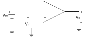
Consider the following non-inverting open loop comparator as shown below in the circuit diagram. The input applied is a sine wave of peak amplitude 6V.The reference voltage is generated from a potential divider as shown in circuit diagram below.
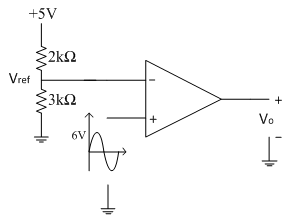
The reference voltage is calculated as
Operation:
The operation of the circuit can be explained with following two conditions
1. When Vin>Vref then Vo=+V_sat
2. When Vin<Vref then Vo=-V_sat
Operation:
The operation of the circuit can be explained with following two conditions
1. When Vin>Vref then Vo=+V_sat
2. When Vin<Vref then Vo=-V_sat
From the output waveforms shown above, input signal crosses the reference point of 3V at two points in the positive half cycle of input signal. Therefore at the two crossing points we can have the equation
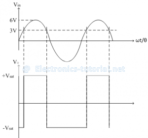
Thus at θ = 30̊, input signal crosses the reference point. Since there are two reference points in the positive half cycle of input signal and both are symmetric from both the ends. So we get two angles corresponding to two crossings as follows,
Thus at θ = 30̊, input signal crosses the reference point. Since there are two reference points in the positive half cycle of input signal and both are symmetric from both the ends. So we get two angles corresponding to two crossings as follows,
Thus between θ1 = 30̊ to θ2 = 150̊ output voltage is high (+Vsat). The complete cycle of input signal corresponds to θ = 360̊.
Thus the duty cycle of the output square wave can be represented as follows,
Thus the duty cycle of the output square wave is 33.33%
If now input signal is changed to have amplitude of 10V peak, the duty cycle calculations are becomes
10sinθ=3
sinθ= 3/10
∴θ= sin^(-1)(0.3)
∴θ=17.45°
So the two angles corresponding to two crossings are calculated as follows
θ1=17.45°-0° θ2=180°-17.45°
θ1=17.45° θ2=162.55°
Thus between θ1 = 17.45° to θ2 = 162.55° output voltage is high (+Vsat). The complete cycle of input signal corresponds to θ = 360̊.
Thus the duty cycle of the output square wave can be represented as follows
D= TON/T
∴D= (θ2-θ1)/θ
∴D= (162.55° -17.45°)/(360°)
∴D= (145.10°)/(360°)
∴D= 0.4030
∴D= 40.30 %
Thus the duty cycle of the output square wave is 40.30 %
Thus as the magnitude of the input signal increases, the duty cycle of the output square wave is also increases. Hence the comparator acts as a duty cycle controller.
RETURN IN ELECTRONIC CRCUIT
Nodes, Branches and Loops of a Circuit
node, branch and loop. As per definition, an electric network is a combination of interconnected circuit elements. A network may or may not provide closed path to the electric current to flow. But, an electrical circuit may be a combination of one or more networks which gives closed path to the electric current. That means, when one or more networks are interconnected together to complete one or more paths to the current, an electric circuit is formed.
Nodes of Electric Circuit
The point through which an circuit element is connected to the circuit is called node. It is better to say, node is a point where, terminal of two or more circuit elements are connected together. Node is a junction point in the circuit. In the above circuit nodes are indicated by bullets.
Finally, the circuit can be redrawn as,

Branch of Electric Circuit
The elements connected to an electric circuit is generally two terminal element. When, one circuit element is connected to the circuit, it connects itself through both of its terminals, to be a part of a closed path.
Any of the circuit elements, when connected to the circuit, it is definitely connected between two nodes of the circuit. When an element exists between two nodes, the path from one node to another through this element is called branch of the circuit.
The branch of an electric circuit can be defined more precisely, as the portion of the circuit between two nodes which can deliver or absorb energy. As per this definition, the short circuit between two nodes is not referred as branch of electric circuit.

Loops in Electric Circuit
An electric circuit has numbers of nodes. If one starts from one node and after going through a set of nodes returns to same starting node without crossing any of the intermediate node twice, he has travels through one loop of the circuit.
PID Control
PID control stands for proportional plus derivative plus integral control. PID control is a feedback mechanism which is used in control system. This type of control is also termed as three term control. By controlling the three parameters - proportional, integral and derivative we can achieve different control actions for specific work. PID is considered to be the best controller in the control system family. Nicholas Minorsky published the theoretical analysis paper on PID controller. For PID control the actuating signal consists of proportional error signal added with derivative and integral of the error signal. Therefore, the actuating signal for PID control is -


There are some control actions which can be achieved by using any of the two parameters of the PID controller. Two parameters can work while keeping the third one to zero. So PID controller becomes sometimes PI (Proportion integral), PD (proportional derivative) or even P or I. The derivative term D is responsible for noise measurement while integral term is meant for reaching the targeted value of the system. In early days PID controller was used as mechanical device. These were pneumatic controllers as they were compressed by air. Mechanical controllers include spring, lever or mass. Many complex electronic systems are provided with PID control loop. In modern days PID controllers are used in PLC (programmable logic controllers) in the industry. The proportional, derivative and integral parameters can be expressed as - Kp, Kd and Ki. All these three parameters have effect on the closed loop control system. It affects rise time, settling time and overshoot and also the steady state error.
| Control Response | Rise time | Settling time | Overshoot | Steady state error |
| Kp | decrease | small change | increase | decrease |
| Kd | small change | decrease | decrease | no change |
| Ki | decrease | increase | increase | eliminate |
Derivative Control: The actuating signal consists of proportional error signal added with derivative of the error signal. Therefore, the actuating signal for derivative control action is given by,
 Integral Control: For integral control action the actuating signal consists of proportional error signal added with integral of the error signal. Therefore, the actuating signal for integral control action is given by
 PID controller has some limitations also apart from being one of the best controllers in control action system. PID control is applicable to many control actions but it does not perform well in case of optimal control. Main disadvantage is the feedback path. PID is not provided with any model of the process. Other drawbacks are that PID is linear system and derivative part is noise sensitive. Small amount of noise can cause great change in the output .
Integral Control: For integral control action the actuating signal consists of proportional error signal added with integral of the error signal. Therefore, the actuating signal for integral control action is given by
PID controller has some limitations also apart from being one of the best controllers in control action system. PID control is applicable to many control actions but it does not perform well in case of optimal control. Main disadvantage is the feedback path. PID is not provided with any model of the process. Other drawbacks are that PID is linear system and derivative part is noise sensitive. Small amount of noise can cause great change in the output . Digital Data of Control System
So let us discuss first some advantages of digital system over analog system.
- Power consumption is less in digital system as compared to analog system.
- Digital systems can handle non linear system easily which is the most important advantage of digital data in control system.
- Digital systems works on the logical operations due to this they show decision making property which is very useful in the present world of machines.
- They are more reliable as compared to analog systems.
- Digital systems are easily available in compact size and have light weight.
- They works on instructions we can program them as per our needs hence we can they are more versatile than analog systems.
- Various complex tasks can be performed easily by the help of digital technology with a high degree of accuracy.
Sampling Process
Sampling process is defined as the conversion of analog signal into the digital signal with the help of a switch (also known as sampler). A sampler is a continuous ON and OFF switch which directly converts analog signals into digital signals. We may have a series connection of sampler depending upon the conversion of signals we use them. For an ideal sampler, the width of the output pulse is very small (tending to zero). Now when talk about discrete system it is very important to know about the z transformations. We will discuss here about the z transformations and its utilities in discrete system. Role of z transformation in discrete systems is same as Fourier transform in continuous systems. Now let us discuss z transformation in detail. We define z transform as Where, F(k) is a discrete data
Z is a complex number
F (z) is Fourier transform of f (k).
Where, F(k) is a discrete data
Z is a complex number
F (z) is Fourier transform of f (k). such that p and q are constants, now on taking the Laplace transform we have by property of linearity:

 then we have by change of scale property

 Now let us discuss some important z transforms and I will suggest readers to learn these transforms:
 Laplace transformation of this function is 1/s2 and the corresponding f(k) = kT. Now the z transformation of this function is
 Function f (t) = t2: Laplace transformation of this function is 2/s3 and the corresponding f(k) = kT. Now the z transformation of this function is

 Laplace transformation of this function is 1/(s + a) and the corresponding f(k) = e(-akT). Now the z transformation of this function is
 Laplace transformation of this function is 1/(s + a)2 and the corresponding f(k) = Te-akT. Now the z transformation of this function is
 Laplace transformation of this function is a/(s2 + a2) and the corresponding f(k) = sin(akT). Now the z transformation of this function is
 Laplace transformation of this function is s/(s2 + a2) and the corresponding f(k) = cos(akT). Now the z transformation of this function is
 Now sometime there is a need to sample data again, which means converting discrete data into continuous form. We can convert digital data of control system into continuous form by hold circuits which are discussed below:
Hold Circuits: These are the circuits which converts discrete data into continuous data or original data. Now there are two types of Hold circuits and they are explained in detail:
Zero Order Hold Circuit
The block diagram representation of the zero order hold circuit is given below:
Figure related to zero order hold.
In the block diagram we have given an input f(t) to the circuit, when we allow input signal to pass through this circuit it reconverts the input signal into continuous one. The output of the zero order hold circuit is shown below.
Now we are interested in finding out the transfer function of the zero order hold circuit. On writing the output equation we have
 on taking the Laplace transform of the above equation we have
 From the above equation we can calculate transfer function as
 On substituting s=jω we can draw the bode plot for the zero order hold circuit. The electrical representation of the zero order hold circuit is shown below, which consists of a sampler connected in series with a resistor and this combination is connected with a parallel combination of resistor and capacitor.

on taking the Laplace transform of the above equation we have
From the above equation we can calculate transfer function as
On substituting s=jω we can draw the bode plot for the zero order hold circuit. The electrical representation of the zero order hold circuit is shown below, which consists of a sampler connected in series with a resistor and this combination is connected with a parallel combination of resistor and capacitor.
 GAIN PLOT - frequency response curve of ZOH
 PHASE PLOT - frequency response curve of ZOH
First Order Hold Circuit The block diagram representation of the first order hold circuit is given below:

In the block diagram we have given an input f(t) to the circuit, when we allow input signal to pass through this circuit it reconverts the input signal into continuous one. The output of the first order hold circuit is shown below: Now we are interested in finding out the transfer function of the first order hold circuit. On writing the output equation we have
 On taking the Laplace transform of the above equation we have
 From the above equation we can calculate transfer function as (1-e-sT)/s. on substituting s=jω we can draw the bode plot for the zero order hold circuit. The bode plot for the first order hold circuit is shown below which consists of a magnitude plot and a phase angle plot.The magnitude plot starts with magnitude value 2π/ωs.

+++++++++++++++++++++++++++++++++++++++++++++++++++++++++++++++++++++++
e- DIREW CIRCUIT AS LIKE AS BASIC PROGRAMMING LANGUAGE INSTRUCTIONS

ASCII CODE
++++++++++++++++++++++++++++++++++++++++++++++++++++++++++++++++++++++++
Tidak ada komentar:
Posting Komentar