All electronic equipment is formed from 4 components, namely 1. input or sensor components (Information and data components) ---> 2. Process components (work components) ---> 3. Output components (output transducer components commonly called actuators) - -> Components of Settings or evaluation programs (elimination and substitution components). all these electronic components are usually driven by DC sources or direct current, where direct current is used there are usually 2 pieces namely artificial direct current (adapters and artificial DC) and pure direct current (battery and battery and solar cells). One-sided sources given to electronic equipment such as LED TVs, Hand Phones, Sattelites , DVDs and organs, computers and radios are usually determined by their DC sources, which are DC sources that are increasingly unidirectional or purer, so that the appearance and performance of electronic equipment increasingly has performance. high quality electronic equipment and long life. now let's review the DC source given to one of the electronic components namely LED which is one of the modern optical components in the field of electronics because LED technology continues to undergo modification both in terms of characteristics and work methods and functions.
So before
Signature -> Gen. Mac Tech
AC vs. DC (Alternating Current vs. Direct Current)
Electricity flows in two ways: either in an alternating current (AC) or in a direct current (DC). Electricity or "current" is nothing but the movement of electrons through a conductor, like a wire. The difference between AC and DC lies in the direction in which the electrons flow. In DC, the electrons flow steadily in a single direction, or "forward." In AC, electrons keep switching directions, sometimes going "forward" and then going "backward."
Alternating current is the best way to transmit electricity over large distances.
Comparison chart
| Alternating Current | Direct Current | |
|---|---|---|
| Amount of energy that can be carried | Safe to transfer over longer city distances and can provide more power. | Voltage of DC cannot travel very far until it begins to lose energy. |
| Cause of the direction of flow of electrons | Rotating magnet along the wire. | Steady magnetism along the wire. |
| Frequency | The frequency of alternating current is 50Hz or 60Hz depending upon the country. | The frequency of direct current is zero. |
| Direction | It reverses its direction while flowing in a circuit. | It flows in one direction in the circuit. |
| Current | It is the current of magnitude varying with time | It is the current of constant magnitude. |
| Flow of Electrons | Electrons keep switching directions - forward and backward. | Electrons move steadily in one direction or 'forward'. |
| Obtained from | A.C Generator and mains. | Cell or Battery. |
| Passive Parameters | Impedance. | Resistance only |
| Power Factor | Lies between 0 & 1. | it is always 1. |
| Types | Sinusoidal, Trapezoidal, Triangular, Square. | Pure and pulsating. |
Converter vs. Inverter
Converters and inverters are electrical devices that convert current. Converters convert the voltage of an electric device, usually alternating current (AC) to direct current (DC). On the other hand, inverters convert direct current (DC) to alternating current (AC).
Comparison chart
| Converter | Inverter | |
|---|---|---|
| What it is | Electrical devices that convert the voltage from alternating current (AC) to direct current (DC). | Electrical devices that convert the voltage from direct current (DC) to alternating current (AC). |
| Types | Analog-to-digital converter (ADC) Digital-to-analog converter (DAC) Digital-to-digital converter (DDC) | Square wave inverter Quasi wave or Modified square wave inverter True/Pure Sine wave inverters |
| Applications | Convert AC to DC; detect amplitude modulated radio signals; supply polarized voltage for welding. | Convert DC electricity from solar panels, batteries or fuel cells to AC; micro-inverters for converting DC power from solar panels to AC for the electric grid; UPS uses inverter to supply AC power when main power is unavailable; induction heating. |
| Disadvantages | Poor current overload capacity; better quality Automatic regulators are more expensive than Mechanical regulators. | Not ideal for inductive AC and motor loads; sensitive electronic devices can be damaged by poor waveforms by low batteries. |
DC (direct current)
DC (direct current) is the unidirectional flow or movement of electric charge carriers (which are usually electrons). The intensity of the current can vary with time, but the general direction of movement stays the same at all times. As an adjective, the term DC is used in reference to voltage whose polarity never reverses.
In a DC circuit, electrons emerge from the negative, or minus, pole and move towards the positive, or plus, pole. Nevertheless, physicists define DC as traveling from plus to minus.
Direct current is produced by electrochemical and photovoltaic cells and batteries. In contrast, the electricity available from utility mains in most countries is AC (alternating current). Utility AC can be converted to DC by means of a power supply consisting of a transformer, a rectifier (which prevents the flow of current from reversing), and a filter (which eliminates current pulsations in the output of the rectifier).
Virtually all electronic and computer hardware needs DC to function. Most solid-state equipment requires between 1.5 and 13.5 volts. Current demands can range from practically zero for an electronic wristwatch to more than 100 amperes for a radio communications power amplifier. Equipment using vacuum tubes, such as a high-power radio or television broadcast transmitter or a CRT (cathode-ray tube) display, require from about 150 volts to several thousand volts DC.
Battery power vs Linear Power Supply
Battery is the low noise of power supply, right? The most common assumption is that because they are a pure DC source they must have no AC noise. In theory .
more truth about battery.
The way battery produces power
Battery produce and provide the power through a chemical reaction. Every type of battery will have a slightly different chemical mixture that is used to generate power. Lithium Ion, SLA and others amount totally 150+ types of battery.
As a battery drains, the amount of chemical compound available to produce electricity reduced. That means there’s an exponential decay on the amount of power a battery can produce. So a battery at 100% will have far more capability of producing fast transients, on opposite, battery will be much LESS ideal right after it start discharging, especially below its 50% capacity.
The even worse situation is: Depending on what type of manufacturing process and what is the stage of living cycle of that battery will create quite a different result.
So that is why you could hear people say: Use NEW battery, charge them close to 100% will make the sound better… And the funny thing is: You will make the new battery wore out sooner if you charge them more frequently.
Battery noise generation
Batteries have a substantial amount of high frequency ripple. This means there is a large AC noise to the DC output voltage. Battery’s chemical reaction will generate different types and frequencies of noise. The chemical reaction changes as the battery drains. That means the spectrum of noise changes as well. As a battery drains so does the output current and the output voltage. As these elements change the voltage will become less stable and the transient response slower.
So ultimately you are creating a non-constant source that has varying spectrums of noise, that is constantly changing, and produces the exact noise we want to get rid of.
Battery vs SMPS (switched-mode power supply)
Battery’s noise generated is usually very high frequency noise up into the Mega Hz or Giga Hz ranges. This is not only more difficult to filter, but it’s the exact noise we hate the most. The noise generated may be less than the noise filtered out compared to a SMPS, but it is still generating noise that is a challenge to compensate for.
So Battery is better than SMPS, but still not the best.
Recharging the Battery
No need to say, recharging is also a problem.
Automatic detection seems a good start, but that will also invoking chargers only begin trickle charging when a battery is below a certain charge level. Introducing AC noise into the battery’s path means the system has to filter out both AC noise and battery noise BOTH.
No so good.
The other possible way is: Use manual switch recharging.
It’s better for noise generation, but no so good for users like me. Well, I hate to PAUSE or CHECK if my battery is still there when I listen to my favor 1.5-hour Mahler Symphony.
Even bigger issue here: Grounding
By using a battery you are no longer connected to ground in the same way. The whole device is either isolated to earth ground or direct depend on the computer’s ground other other devices’ ground. This means that shields become a noise “cage” and in addition, you end up easily having ground loops along cables and your system must find an alternative path for ground noise. finding these ground loop is NOT easy.
Linear Power Supply with Super Quiet DC circuit
Unlike battery, LPS can be built to a much higher bandwidth and much stabilized voltage and current capacity. Usually, a well-designed LPS can be considerably lower noise, higher bandwidth and more powerful supply than battery.
The only two issues for LPS are: Weight and Cost.
A good LPS is heavy. Seems no quick solution for the last 30 years. More wattage you need, more heavier it is. Especially the transformers and big Caps.
A good LPS is not cheap.
Conclusion
Battery is definitely better than SMPS and not too heavy and costly.
Well designed Linear Power Supply could be even better with two issues: Weight and Cost.
So this is the choice that everybody has to made.
AC-DC Converters
With robust, advanced high-voltage converters, power factor correctors, a variety of controllers and supervisors/housekeeping ICs, together with innovative architectures and extended temperature ranges, ST can offer integrated solutions and meet all switching-mode power supply design needs.
New generation AC-DC converters reduce power consumption and increase efficiency, essential for powering the majority of mains equipment. When combined together, ST power factor correctors, PWM controllers and offline converters significantly lower system power consumption to outperform the most demanding energy-saving regulations .
Charging with a Power Supply
how to charge a battery without a designated charger.
Batteries can be charged manually with a power supply featuring user-adjustable voltage and current limiting. I stress manual because charging needs the know-how and can never be left unattended; charge termination is not automated. Because of difficulties in detecting full charge with nickel-based batteries, I recommend charging only lead and lithium-based batteries manually.
Batteries can be charged manually with a power supply featuring user-adjustable voltage and current limiting. I stress manual because charging needs the know-how and can never be left unattended; charge termination is not automated. Because of difficulties in detecting full charge with nickel-based batteries, I recommend charging only lead and lithium-based batteries manually.
Lead Acid
Before connecting the battery, calculate the charge voltage according to the number of cells in series, and then set the desired voltage and current limit. To charge a 12-volt lead acid battery (six cells) to a voltage limit of 2.40V, set the voltage to 14.40V (6 x 2.40). Select the charge current according to battery size. For lead acid, this is between 10 and 30 percent of the rated capacity. A 10Ah battery at 30 percent charges at about 3A; the percentage can be lower. An 80Ah starter battery may charge at 8A. (A 10 percent charge rate is equal to 0.1C.)
Observe the battery temperature, voltage and current during charge. Charge only at ambient temperatures in a well-ventilated room. Once the battery is fully charged and the current has dropped to 3 percent of the rated Ah, the charge is completed. Disconnect the charge. Also disconnect the charge after 16–24 hours if the current has bottomed out and cannot go lower; high self-discharge (soft electrical short) can prevent the battery from reaching the low saturation level. If you need float charge for operational readiness, lower the charge voltage to about 2.25V/cell.
You can also use the power supply to equalize a lead acid battery by setting the charge voltage 10 percent higher than recommended. The time in overcharge is critical and must be carefully observed
A power supply can also reverse sulfation. Set the charge voltage above the recommended level, adjust the current limiting to the lowest practical value and observe the battery voltage. A totally sulfated lead acid may draw very little current at first and as the sulfation layer dissolves, the current will gradually increase. Elevating the temperature and placing the battery on an ultrasound vibrator may also help in the process. If the battery does not accept a charge after 24 hours, restoration is unlikely.
Lithium-ion
Lithium-ion charges similarly to lead acid and you can also use the power supply but exercise extra caution. Check the full charge voltage, which is commonly 4.20V/cell, and set the threshold accordingly. Make certain that none of the cells connected in series exceeds this voltage. (The protection circuit in a commercial pack does this.) Full charge is reached when the cell(s) reach 4.20V/cell voltage and the current drops to 3 percent of the rated current, or has bottomed out and cannot go down further. Once fully charged, disconnect the battery. Never allow a cell to dwell at 4.20V for more than a few hours
Please note that not all Li-ion batteries charge to the voltage threshold of 4.20V/cell. Lithium iron phosphate typically charges to the cut-off voltage of 3.65V/cell and lithium-titanate to 2.85V/cell. Some Energy Cells may accept 4.30V/cell and higher. It is important to observe these voltage limits.
NiCd and NiMH
Charging nickel-based batteries with a power supply is challenging because the full-charge detection is rooted in a voltage signature that varies with the applied charge current. If you must charge NiCd and NiMH with a regulated power supply, use the temperature rise on a 0.3–1C rapid charge as an indication of full charge. When charging at a low current, estimate the level of remaining charge and calculate the charge time. An empty 2Ah NiMH will charge in about 3 hours at 750–1,000mA. The trickle charge, also known as maintenance charge, must be reduced to 0.05C
XO___XO LED Lights

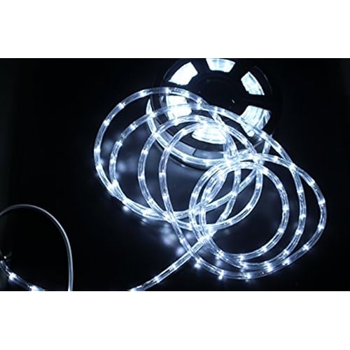
LED lights offer several benefits for vehicle and equipment operators, including bright, white wide spot patterns, low amp draw, rugged durability and zero maintenance. Constructed with aluminum housings, metalized polycarbonate reflectors, high powered LEDs, 100% optically pure acrylic LED lenses and shatterproof polycarbonate lens covers, these LED emitters are designed to provide a bright, uniform light pattern in tough environments. Rated dust and water tight at IP68 (ingress protection) and supported with rubber shock isolators, these LED emitter lights run on any voltage between 9 volts and 32 volts, providing a versatile lighting source for industrial, military, mining, security, boating and off road applications.
LED emitter lights uses a patent pending LED and reflector combination to provide a high powered, projected light source for vehicles, heavy equipment and security applications. Each LED is combined with its own reflector and clustered into an array. As a result, these LED lights emit a wide spot pattern (or a modified spot pattern) which falls in between a narrow spot and a flood pattern. We can also provide long distance spot and short, wide flood beams as well.


Modern lights
Today, street lighting commonly uses high-intensity discharge lamps. Low-pressure sodium lamps became commonplace after World War II for their low power consumption and long life. Late in the 20th century HPS high pressure sodium lamps were preferred, taking further the same virtues.[17] Such lamps provide the greatest amount of photopic illumination for the least consumption of electricity. However, white light sources have been shown to double driver peripheral vision and improve driver brake reaction time by at least 25%; to enable pedestrians to better detect pavement trip hazards[18] and to facilitate visual appraisals of other people associated with interpersonal judgements. Studies comparing metal halide and high-pressure sodium lamps have shown that at equal photopic light levels, a street scene illuminated at night by a metal halide lighting system was reliably seen as brighter and safer than the same scene illuminated by a high pressure sodium system.]
Two national standards now allow for variation in illuminance when using lamps of different spectra. In Australia, HPS lamp performance needs to be reduced by a minimum value of 75%. In the UK, illuminances are reduced with higher values S/P ratio
New street lighting technologies, such as LED or induction lights, emit a white light that provides high levels of scotopic lumens allowing street lights with lower wattages and lower photopic lumens to replace existing street lights. However, there have been no formal specifications written around Photopic/Scotopic adjustments for different types of light sources, causing many municipalities and street departments to hold back on implementation of these new technologies until the standards are updated. Eastbourne in East Sussex UK is currently undergoing a project to see 6000 of its street lights converted to LED and will be closely followed by Hastings in early 2014.[24]
Milan, Italy, is the first major city to have entirely switched to LED lighting.
In North America, the city of Mississauga (Canada) was one of the first and biggest LED conversion projects with over 46,000 lights converted to LED technology between 2012 and 2014. It is also one of the first cities in North America to use Smart City technology to control the lights. DimOnOff, a company based in Quebec City, was chosen as a Smart City partner for this project.
Photovoltaic-powered LED luminaires are gaining wider acceptance. Preliminary field tests show that some LED luminaires are energy-efficient and perform well in testing environments.
In 2007, the Civil Twilight Collective created a variant of the conventional LED streetlight, namely the Lunar-resonant streetlight. These lights increase or decrease the intensity of the streetlight according to the lunar light. This streetlight design thus reduces energy consumption as well as light pollution.
Measurement


Two very similar measurement systems were created to bridge the scotopic and photopic luminous efficiency functions, creating a Unified System of Photometry. This new measurement has been well-received because the reliance on V(λ) alone for characterizing night-time light illuminations requires more electric energy. The cost-savings potential of using a new way to measure mesopic lighting scenarios is tremendous.[36]
Outdoor Site-Lighting Performance (OSP) is a method for predicting and measuring three different aspects of light pollution: glow, trespass and glare.[37] Using this method, lighting specifiers can quantify the performance of existing and planned lighting designs and applications to minimize excessive or obtrusive light leaving the boundaries of a property.
Advantages
Major advantages of street lighting include prevention of accidents and increase in safety. Studies have shown that darkness results in a large number of crashes and fatalities, especially those involving pedestrians; pedestrian fatalities are 3 to 6.75 times more likely in the dark than in daylight. Several decades ago when automobile crashes were far more common, street lighting was found to reduce pedestrian crashes by approximately 50%.
Furthermore, in the 1970s, lighted intersections and highway interchanges tend to have fewer crashes than unlighted intersections and interchanges.
Towns, cities, and villages use the unique locations provided by lampposts to hang decorative or commemorative banners.
Many communities in the US use lampposts as a tool for fund raising via lamppost banner sponsorship programs first designed by a US based lamppost banner manufacturer.
Disadvantages
The major criticisms of street lighting are that it can actually cause accidents if misused, and cause light pollution.
Health and safety
There are two optical phenomena that need to be recognized in street light installations.
- The loss of night vision because of the accommodation reflex of drivers' eyes is the greatest danger. As drivers emerge from an unlighted area into a pool of light from a street light their pupils quickly constrict to adjust to the brighter light, but as they leave the pool of light the dilation of their pupils to adjust to the dimmer light is much slower, so they are driving with impaired vision. As a person gets older the eye's recovery speed gets slower, so driving time and distance under impaired vision increases.
- Oncoming headlights are more visible against a black background than a grey one. The contrast creates greater awareness of the oncoming vehicle.
- Stray voltage is also a concern in many cities. Stray voltage can accidentally electrify lampposts and has the potential to injure or kill anyone who comes into contact with the post.[46]
There are also physical dangers to the posts of street lamps other than children climbing them for recreational purposes. Street light stanchions (lampposts) pose a collision risk to motorists and pedestrians, particularly those affected by poor eyesight or under the influence of alcohol. This can be reduced by designing them to break away when hit (frangible or collapsible supports), protecting them by guardrails, or marking the lower portions to increase their visibility. High winds or accumulated metal fatigue also occasionally topple street lights.
Light pollution

In urban areas, light pollution can hide the stars and interfere with astronomy and the migration of many bird species.[ In settings near astronomical telescopes and observatories, low pressure sodium lamps may be used. These lamps are advantageous over other lamps such as mercury and metal halide lamps because low pressure sodium lamps emit lower intensity, monochromatic light. Observatories can filter the sodium wavelength out of their observations and virtually eliminate the interference from nearby urban lighting. Full cutoff streetlights also reduce light pollution by reducing the amount of light that is directed at the sky which also improves the luminous efficiency of the light.
Energy consumption
As of 2017, globally 70% of all electricity was generated by burning fossil fuels, a source of air pollution and greenhouse gases, and also globally there are approximately 300 million street lights using that electricity.[48] Cities are exploring more efficient energy use, reducing street light power consumption by dimming lights during off-peak hours and switching to high-efficiency LED lamps A British county council has turned off 5% of its street lights on a trial basis. Typical collector road lighting in New York State costs $6400/mile/year for high pressure sodium at 8.5 kW/mile or $4000 for light-emitting diode luminaires at 5.4 kW/mile.
Street light control systems
Street light controllers are smarter versions of the mechanical or electronic timers previously used for street light ON-OFF operation. They come with energy conservation options like twilight saving, staggering or dimming. Also many street light controllers come with an astronomical clock for a particular location or a Global Positioning System (GPS) connection to give the best ON-OFF time and energy saving.A number of street light control systems have been developed to control and reduce energy consumption of a town's public lighting system. These range from controlling a circuit of street lights and/or individual lights with specific ballasts and network operating protocols. These may include sending and receiving instructions via separate data networks, at high frequency over the top of the low voltage supply or wireless.
Accessories
Some intelligent street light controllers also come with Global System for Mobile Communications (GSM), Radio frequency (RF) or General Packet Radio Service (GPRS) communication, user adjusted according to latitude and longitude(low cost type), for better street light management and maintenance. Many street light controllers also come with traffic sensors to manage the lux level of the lamp according to the traffic and to save energy by decreasing lux when there is no traffic. America, Canada, India and many other countries have started introducing street light controllers to their road lighting for energy conservation, street light management and maintenance purpose.
Economics
Street light controllers can be expensive in comparison with normal timers, and can cost between $100 and $2500, but most of them return the investment between 6 months and 2 years. As the equipment's lifetime is 7 to 10 years it saves energy and cost for some years.
Image-based street light control
A number of companies are now manufacturing Intelligent street lighting that adjust light output based on usage and occupancy, i.e. automating classification of pedestrian versus cyclist, versus automotive, sensing also velocity of movement and illuminating a certain number of streetlights ahead and fewer behind, depending on velocity of movement. Also the lights adjust depending on road conditions, for example, snow produces more reflectance therefore reduced light is required.
Purpose
There are three distinct main uses of street lights, each requiring different types of lights and placement. Misuse of the different types of lights can make the situation worse by compromising visibility or safety.
Beacon lights

A modest steady light at the intersection of two roads is an aid to navigation because it helps a driver see the location of a side road as they come closer to it and they can adjust their braking and know exactly where to turn if they intend to leave the main road or see vehicles or pedestrians. A beacon light's function is to say "here I am" and even a dim light provides enough contrast against the dark night to serve the purpose. To prevent the dangers caused by a car driving through a pool of light, a beacon light must never shine onto the main road, and not brightly onto the side road. In residential areas, this is usually the only appropriate lighting, and it has the bonus side effect of providing spill lighting onto any sidewalk there for the benefit of pedestrians. On Interstate highways this purpose is commonly served by placing reflectors at the sides of the road.
Roadway lights


Because of the dangers discussed above, roadway lights are properly used sparingly and only when a particular situation justifies increasing the risk. This usually involves an intersection with several turning movements and much signage, situations where drivers must take in much information quickly that is not in the headlights' beam. In these situations (A freeway junction or exit ramp) the intersection may be lit so that drivers can quickly see all hazards, and a well designed plan will have gradually increasing lighting for approximately a quarter of a minute before the intersection and gradually decreasing lighting after it. The main stretches of highways remain unlighted to preserve the driver's night vision and increase the visibility of oncoming headlights. If there is a sharp curve where headlights will not illuminate the road, a light on the outside of the curve is often justified.
If it is desired to light a roadway (perhaps due to heavy and fast multi-lane traffic), to avoid the dangers of casual placement of street lights it should not be lit intermittently, as this requires repeated eye readjustment which implies eyestrain and temporary blindness when entering and leaving light pools. In this case the system is designed to eliminate the need for headlights. This is usually achieved with bright lights placed on high poles at close regular intervals so that there is consistent light along the route. The lighting goes from curb to curb.
Cycle path lights


Policies that encourage utility cycling have been proposed and implemented, including lighting bike paths to increase safety at night.
Footpath lights
Maintenance

Street lighting systems require ongoing maintenance, which can be classified as either reactive or preventative. Reactive maintenance is a direct response to a lighting failure, such as replacing a discharge lamp after it has failed, or replacing an entire lighting unit after it has been hit by a vehicle. Preventative maintenance is scheduled replacement of lighting components, for example replacing all of the discharge lamps in an area of the city when they have reached 85% of their expected life. In the United Kingdom the Roads Liaison Group has issued a Code of Practice recommending specific reactive and preventative maintenance procedures.[53]
Some street lights in New York City have an orange or red light on top of the luminair (light fixture) or a red light attached to the lamppost. This indicates that near to this lighting pole or in the same intersection, there is a fire alarm pull box.[54] Other street lights have a small red light next to the street light bulb, when the small light flashes, it indicates an issue with the electrical current
Intelligent street lighting
Intelligent street lighting refers to public street lighting that adapts to movement by pedestrians, cyclists and cars. Intelligent street lighting, also referred to as adaptive street lighting, dims when no activity is detected, but brightens when movement is detected. This type of lighting is different from traditional, stationary illumination, or dimmable street lighting that dims at pre-determined times.
Features
Street lights can be made intelligent by placing cameras or other sensors on them, which enables them to detect movement (e.g. Sensity's Light Sensory Network, GE's "Currents") Additional technology enables the street lights to communicate with one another. Different companies have different variations to this technology. When a passer-by is detected by a camera or sensor, it will communicate this to neighboring street lights, which will brighten so that people are always surrounded by a safe circle of light. The SmartLighting technology of the Anhalt University of Applied Sciences does this as well, and has been installed in Bernburg-Strenzfeld in Germany.Street lights illuminate at a longer distance ahead of the pedestrian than behind the pedestrian in the SmartLighting concept.
Control
Some companies also offer software with which the street lights can be monitored and managed wirelessly. Clients, or other companies, can access the software from a computer, or even a tablet. From this software, they can gather data, pre-set levels of brightness and dimming time; receive warning signals when a light defects.
Light-Emitting Diodes (LEDs)
Introduction
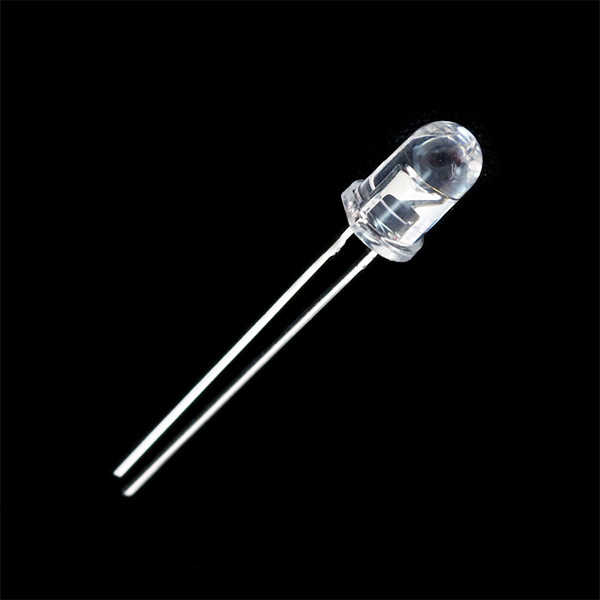
LEDs are all around us: In our phones, our cars and even our homes. Any time something electronic lights up, there’s a good chance that an LED is behind it. They come in a huge variety of sizes, shapes, and colors, but no matter what they look like they have one thing in common: they’re the bacon of electronics. They’re widely purported to make any project better and they’re often added to unlikely things (to everyone’s delight).
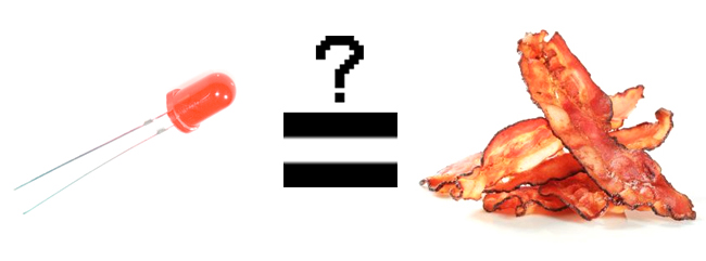
Unlike bacon, however, they’re no good once you’ve cooked them. This guide will help you avoid any accidental LED barbecues! First things first, though. What exactly is this LED thing everyone’s talking about?
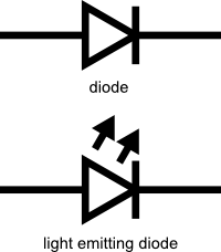
LEDs (that’s “ell-ee-dees”) are a particular type of diode that convert electrical energy into light. In fact, LED stands for “Light Emitting Diode.” (It does what it says on the tin!) And this is reflected in the similarity between the diode and LED schematic symbols:
In short, LEDs are like tiny lightbulbs. However, LEDs require a lot less power to light up by comparison. They’re also more energy efficient, so they don’t tend to get hot like conventional lightbulbs do (unless you’re really pumping power into them). This makes them ideal for mobile devices and other low-power applications. Don’t count them out of the high-power game, though. High-intensity LEDs have found their way into accent lighting, spotlights and even automotive headlights!
How to Use Them
So you’ve come to the sensible conclusion that you need to put LEDs on everything. We thought you’d come around.
Let’s go over the rule book:
1) Polarity Matters
In electronics, polarity indicates whether a circuit component is symmetric or not. LEDs, being diodes, will only allow current to flow in one direction. And when there’s no current-flow, there’s no light. Luckily, this also means that you can’t break an LED by plugging it in backwards. Rather, it just won’t work.
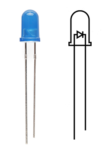
The positive side of the LED is called the “anode” and is marked by having a longer “lead,” or leg. The other, negative side of the LED is called the “cathode.” Current flows from the anode to the cathode and never the opposite direction. A reversed LED can keep an entire circuit from operating properly by blocking current flow. So don’t freak out if adding an LED breaks your circuit. Try flipping it around.
2) Moar Current Equals Moar Light
The brightness of an LED is directly dependent on how much current it draws. That means two things. The first being that super bright LEDs drain batteries more quickly, because the extra brightness comes from the extra power being used. The second is that you can control the brightness of an LED by controlling the amount of current through it. But, setting the mood isn’t the only reason to cut back your current.
3) There is Such a Thing as Too Much Power
If you connect an LED directly to a current source it will try to dissipate as much power as it’s allowed to draw, and, like the tragic heroes of olde, it will destroy itself. That’s why it’s important to limit the amount of current flowing across the LED.
For this, we employ resistors. Resistors limit the flow of electrons in the circuit and protect the LED from trying to draw too much current. Don’t worry, it only takes a little basic math to determine the best resistor value to use. You can find out all about it in the example applications of our resistor tutorial!
Don’t let all of this math scare you, it’s actually pretty hard to mess things up too badly. In the next section, we’ll go over how to make an LED circuit without getting your calculator.
LEDs Without Math
Before we talk about how to read a datasheet, let’s hook up some LEDs. After all, this is an LED tutorial, not a reading tutorial.
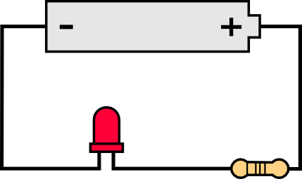
It’s also not a math tutorial, so we’ll give you a few rules of thumb for getting LEDs up and running. As you’ve probably put together from the info in the last section, you’ll need a battery, a resistor and an LED. We’re using a battery as our power source, because they’re easy to find and they can’t supply a dangerous amount of current.
The basic template for an LED circuit is pretty simple, just connect your battery, resistor and LED in series. Like this:
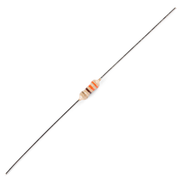
330 Ohm Resistor
A good resistor value for most LEDs is 330 Ohms ( orange - orange - brown ). You can use the information from the last section to help you determine the exact value you need, but this is LEDs without math… So, start by popping a 330 Ohm resistor into the above circuit and see what happens.
Trial and Error
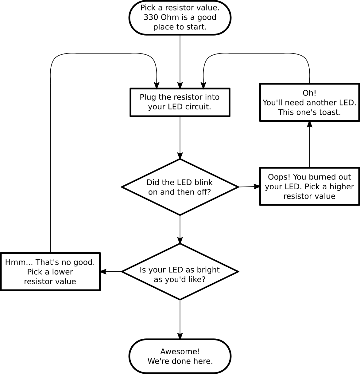
The interesting thing about resistors is that they’ll dissipate extra power as heat, so if you have a resistor that’s getting warm, you probably need to go with a smaller resistance. If your resistor is too small, however, you run the risk of burning out the LED! Given that you have a handful of LEDs and resistors to play with, here’s a flow chart to help you design your LED circuit by trial and error:
Throwies with a Coin Cell Battery
Another way to light up an LED is to just connect it to a coin cell battery! Since the coin cell can’t source enough current to damage the LED, you can connect them directly together! Just push a CR2032 coin cell between the leads of the LED. The long leg of the LED should be touching the side of the battery marked with a “+”. Now you can wrap some tape around the whole thing, add a magnet, and stick it to stuff! Yay for throwies!
Of course, if you’re not getting great results with the trial and error approach, you can always get out your calculator and math it up. Don’t worry, it’s not hard to calculate the best resistor value for your circuit. But before you can figure out the optimal resistor value, you’ll need to find the optimal current for your LED. For that we’ll need to report to the datasheet…
Get the Details
Don’t go plugging any strange LEDs into your circuits, that’s just not healthy. Get to know them first. And how better than to read the datasheet.
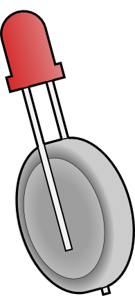
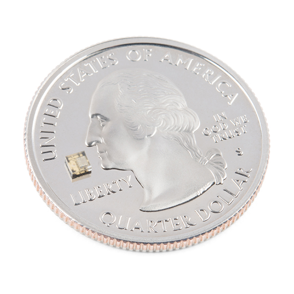
As an example we’ll peruse the datasheet for our Basic Red 5mm LED.
LED Current
Starting at the top and making our way down, the first thing we encounter is this charming table:
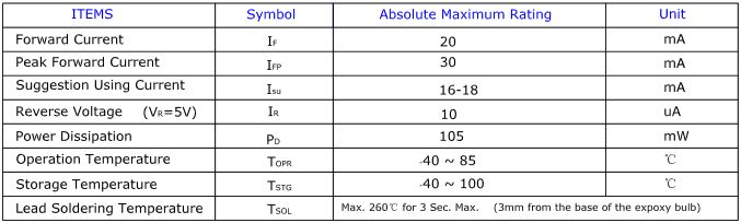
Ah, yes, but what does it all mean?
The first row in the table indicates how much current your LED will be able to handle continuously. In this case, you can give it 20mA or less, and it will shine its brightest at 20mA. The second row tells us what the maximum peak current should be for short bursts. This LED can handle short bumps to 30mA, but you don’t want to sustain that current for too long. This datasheet is even helpful enough to suggest a stable current range (in the third row from the top) of 16-18mA. That’s a good target number to help you make the resistor calculations we talked about.
The following few rows are of less importance for the purposes of this tutorial. The reverse voltage is a diode property that you shouldn’t have to worry about in most cases. The power dissipation is the amount of power in milliWatts that the LED can use before taking damage. This should work itself out as long as you keep the LED within its suggested voltage and current ratings.
LED Voltage
Let’s see what other kinds of tables they’ve put in here… Ah!
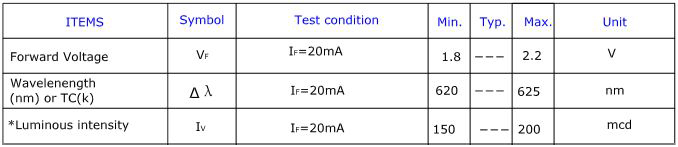
This is a useful little table! The first row tells us what the forward voltage drop across the LED will be. Forward voltage is a term that will come up a lot when working with LEDs. This number will help you decide how much voltage your circuit will need to supply to the LED. If you have more than one LED connected to a single power source, these numbers are really important because the forward voltage of all of the LEDs added together can’t exceed the supply voltage. We’ll talk about this more in-depth later in the delving deeper section of this tutorial.
LED Wavelength
The second row on this table tells us the wavelength of the light. Wavelength is basically a very precise way of explaining what color the light is. There may be some variation in this number so the table gives us a minimum and a maximum. In this case it’s 620 to 625nm, which is just at the lower red end of the spectrum (620 to 750nm). Again, we’ll go over wavelength in more detail in the delving deeper section.
LED Brightness
The last row (labeled “Luminous Intensity”) is a measure of how bright the LED can get. The unit mcd, or millicandela, is a standard unit for measuring the intensity of a light source. This LED has an maximum intensity of 200 mcd, which means it’s just bright enough to get your attention but not quite flashlight bright. At 200 mcd, this LED would make a good indicator.
Viewing Angle
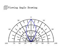
Next, we’ve got this fan-shaped graph that represents the viewing angle of the LED. Different styles of LEDs will incorporate lenses and reflectors to either concentrate most of the light in one place or spread it as widely as possible. Some LEDs are like floodlights that pump out photons in every direction; Others are so directional that you can’t tell they’re on unless you’re looking straight at them. To read the graph, imagine the LED is standing upright underneath it. The “spokes” on the graph represent the viewing angle. The circular lines represent the intensity by percent of maximum intensity. This LED has a pretty tight viewing angle. You can see that looking straight down at the LED is when it’s at its brightest, because at 0 degrees the blue lines intersect with the outermost circle. To get the 50% viewing angle, the angle at which the light is half as intense, follow the 50% circle around the graph until it intersects the blue line, then follow the nearest spoke out to read the angle. For this LED, the 50% viewing angle is about 20 degrees.
Dimensions
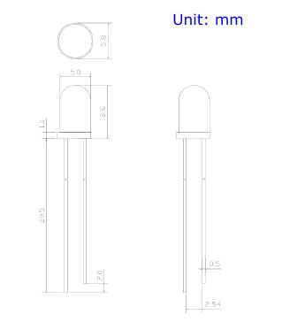
Finally, the mechanical drawing. This picture contains all of the measurements you’ll need to actually mount the LED in an enclosure! Notice that, like most LEDs, this one has a small flange at the bottom. That comes in handy when you want to mount it in a panel. Simply drill a hole the perfect size for the body of the LED, and the flange will keep it from falling through!
Now that you know how to decipher the datasheet, let’s see what kind of fancy LEDs you might encounter in the wild…
Types of LEDs
Congratulations, you know the basics! Maybe you’ve even gotten your hands on a few LEDs and started lighting stuff up, that’s awesome! How would you like to step up your blinky game? Let’s talk about makin' it fancy outside of your standard LED.
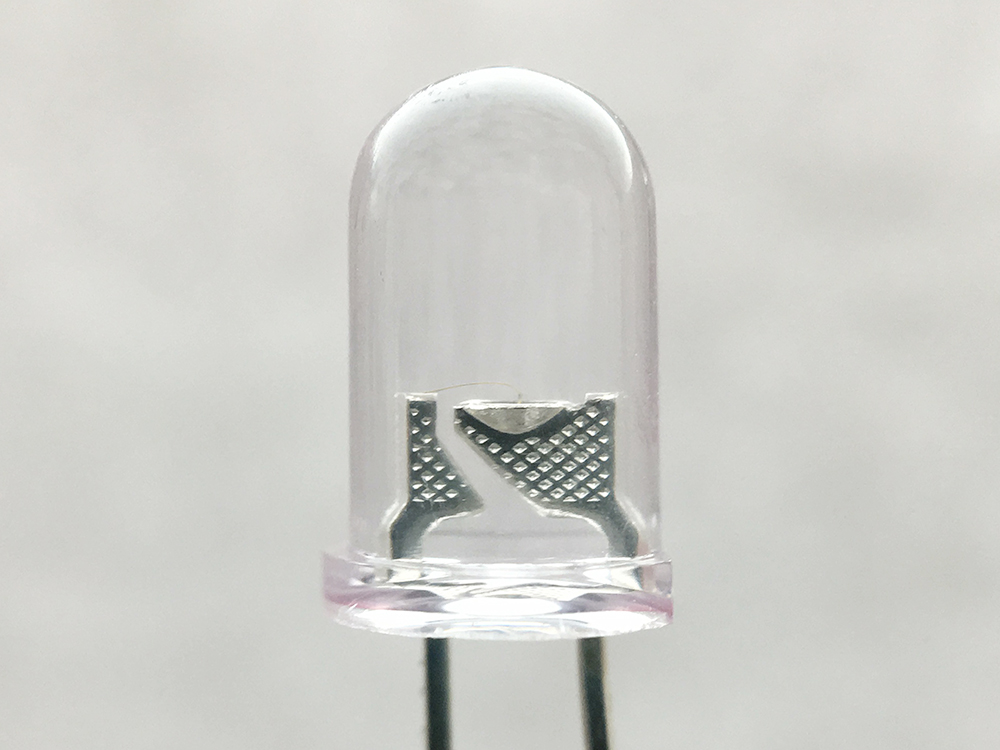
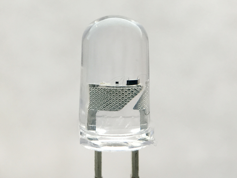
Close Up of Super Bright 5mm LED Close Up
Types of LEDs
Here’s the cast of other characters.
RGB LEDs
RGB (Red-Green-Blue) LEDs are actually three LEDs in one! But that doesn’t mean it can only make three colors. Because red, green, and blue are the additive primary colors, you can control the intensity of each to create every color of the rainbow. Most RGB LEDs have four pins: one for each color, and a common pin. On some, the common pin is the anode, and on others, it’s the cathode.
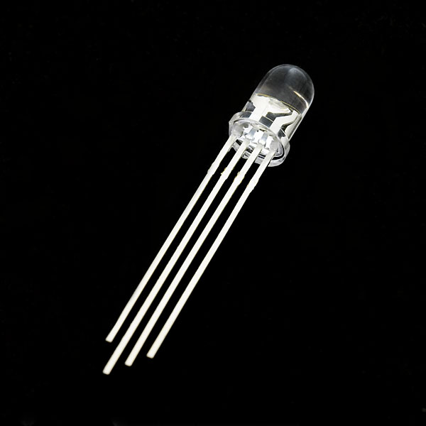
RGB Common Clear Cathode LED
LEDs w/ Integrated Circuits
Cycling
Some LEDs are smarter than others. Take the cycling LED, for example. Inside these LEDs, there’s actually an integrated circuit that allows the LED to blink without any outside controller. Here’s a closeup of the IC (the big, black square chip on the tip of the anvil) controlling the colors.
5mm Slow Cycling LED Close Up
Simply power it up and watch it go! These are great for projects where you want a little bit more action but don’t have room for control circuitry. There are even RGB flashing LEDs that cycle through thousands of colors!
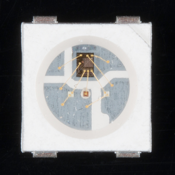
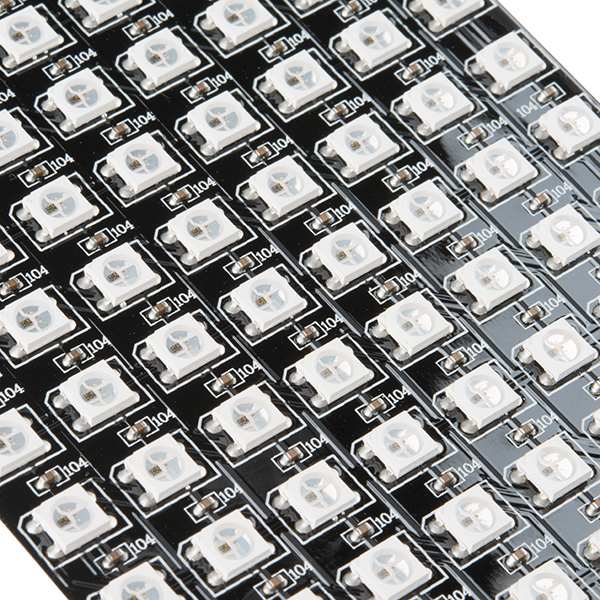
Addressable LEDs
Other types of LEDs can be controlled individually. There are different chipsets (WS2812, APA102, UCS1903, to name a few) used to control an individual LED that is chained together. Below is a closeup of a WS2812. The bigger square IC on the right controls the colors individually.
Addressable WS2812 PTH Close Up
Built-In Resistor
What is this magic? An LED with a built-in resistor? That's right. There are also LEDs that include a small, current limiting resistor. If you look closely at the image below, there is a small, black square IC on the post to limit the current on these types of LEDs.

LED with Built-In Resistor Close Up
So plug the LED with built-in resistor to your power source and light it up! We have tested these types of LEDs at 3.3V, 5V, and 9V.
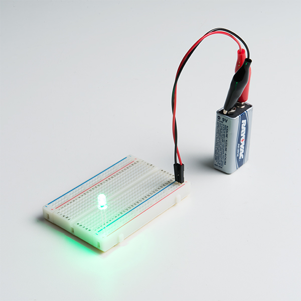
Super Bright Green LED with Built in Resistor Powered
Surface Mount (SMD) Packages
SMD LEDs aren’t so much a specific kind of LED but a package type. As electronics get smaller and smaller, manufacturers have figured out how to cram more components in a smaller space. SMD (Surface Mount Device) parts are tiny versions of their standard counterparts. Here’s a closeup of a WS2812B addressable LED packaged into a small 5050 package.
Addressable WS2812B Close Up
SMD LEDs come in several sizes, from fairly large to smaller than a grain of rice! Because they’re so small, and have pads instead of legs, they’re not as easy to work with, but if you’re tight on space, they might be just what the doctor ordered.
 |  |
| WS2812B-5050 Package | APA102-2020 Package |
SMD LEDs also make it easier and quicker for pick and place machines to populate a lot of LEDs onto PCBs and strips. You would probably not to manually solder all of those components by hand.
 | 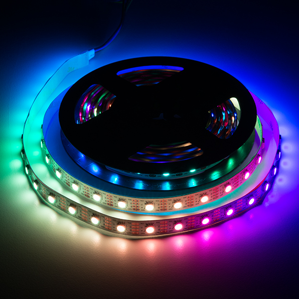 |
| Close Up of 8x32 Addressable (WS2812-5050) LED Matrix | 5M Addressable (APA102-5050) LED Strip Powered |
High Power
High-Power LEDs from manufacturers like Luxeon and CREE, are crazy bright. These are brighter than the super brights! Generally, an LED is considered High-Power if it can dissipate 1 Watt or more of power. These are the fancy LEDs that you find in really nice flashlights. Arrays of them can even be built for spotlights and automobile headlights. Because there’s so much power being pumped through the LED, these often require heatsinks. A heatsink is basically a chunk of heat conducting metal with lots of surface area whose job is to transfer as much waste heat into the surrounding air as possible. There can be some heat dissipation built into the design of some breakout board such as the one shown below.
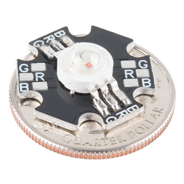 | 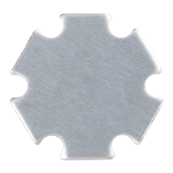 |
| High Power RGB LED | Aluminum Back for some Heat Dissipation |
High-Power LEDs can generate so much waste heat that they’ll damage themselves without proper cooling. Don’t let the term “waste heat” fool you, though, these devices are still incredibly efficient compared to conventional bulbs. To control, you could use a constant current LED driver.
Special LEDs
There are even LEDs that emit light outside of the normal visible spectrum. You probably use infrared LEDs every day, for instance. They’re used in things like TV remotes to send small pieces of information in the form of invisible light! These may look like standard LEDs so it will be hard to distinguish from normal LEDs.
IR LED
On the opposite end of the spectrum you can also get ultraviolet LEDs. Ultraviolet LEDs will make certain materials fluoresce, just like a blacklight! They’re also used for disinfecting surfaces, because many bacteria are sensitive to UV radiation. They may also be used counterfeit detection (bills, credit cards, documents, etc), sun burns, the list goes on. Please wear eye protection when using these LEDs.
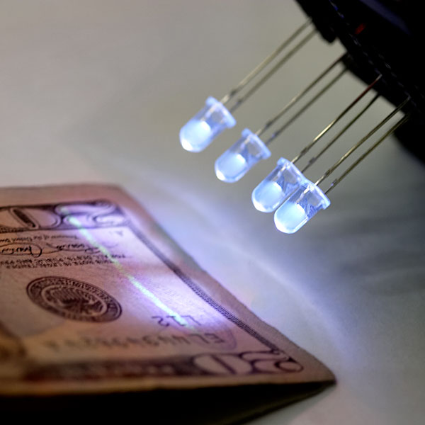
UV LED Inspecting a US Bill
More LEDs
With fancy LEDs like these at your disposal, there’s no excuse for leaving anything un-illuminated. However, if your thirst for LED knowledge hasn’t been slaked, then read on, and we’ll get into the nitty-gritty on LEDs, color, and luminous intensity!
Delving Deeper
So you’ve graduated from LEDs 101 and you want more? Oh, don’t worry, we’ve got more. Let’s start with the science behind what makes LEDs tick… err… blink. We’ve already mentioned that LEDs are a special kind of diode, but let’s delve a little deeper into exactly what that means:
What we call an LED is really the LED and the packaging together, but the LED itself is actually tiny! It’s a chip of semiconductor material that’s doped with impurities which creates a boundary for charge carriers. When current flows into the semi-conductor, it jumps from one side of this boundary to the other, releasing energy in the process. In most diodes that energy leaves as heat, but in LEDs that energy is dissipated as light!
The wavelength of light, and therefore the color, depends on the type of semiconductor material used to make the diode. That’s because the energy band structure of semiconductors differs between materials, so photons are emitted with differing frequencies. Here’s a table of common LED semiconductors by frequency:
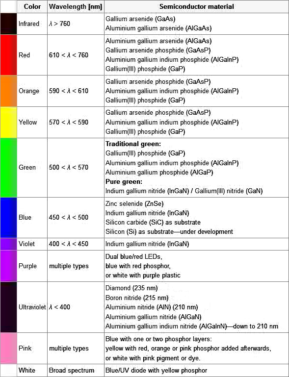
Truncated table of semiconductor materials by color. The full table is available on the Wikipedia entry for “LED”
While the wavelength of the light depends on the band gap of the semiconductor, the intensity depends on the amount of power being pushed through the diode. We talked about luminous intensity a little bit in a previous section, but there’s more to it than just putting a number on how bright something looks.
The unit for measuring luminous intensity is called the candela, although when you’re talking about the intensity of a single LED you’re usually in the millicandela range. The interesting thing about this unit is that it isn’t really a measure of the amount of light energy, but an actual measure of “brightness”. This is achieved by taking the power emitted in a particular direction and weighting that number by the luminosity function of the light. The human eye is more sensitive to some wavelengths of light than others, and the luminosity function is a standardized model that accounts for that sensitivity.
The luminous intesity of LEDs can range from the tens to the tens-of-thousands of millicandela. The power light on your TV is probably about 100 mcd, whereas a good flashlight might be 20,000 mcd. Looking straight into anything brighter than a few thousand millicandela can be painful; don’t try it.
Forward Voltage Drop
Oh, I also promised that we’d talk about the concept of Forward Voltage Drop. Remember when we were looking at the datasheet and I mentioned that the Forward Voltage of all of your LEDs added together can’t exceed your system voltage? This is because every component in your circuit has to share the voltage, and the amount of voltage that every part uses together will always equal the amount that’s available. This is called Kirchhoff’s Voltage Law. So if you have a 5V power supply and each of your LEDs have a forward voltage drop of 2.4V then you can’t power more than two at a time.
Kirchhoff’s Laws also come in handy when you want to approximate the voltage across a given part based on the Forward Voltage of other parts. For instance, in the example I just gave there’s a 5V supply and 2 LEDs with a 2.4V Forward Voltage Drop each. Of course we would want to include a current limiting resistor, right? How would you find out the voltage across that resistor? It’s easy:
5 (System Voltage) = 2.4 (LED 1) + 2.4 (LED 2) + Resistor5 = 4.8 + ResistorResistor = 5 - 4.8Resistor = 0.2
So there is .2V across the resistor! This is a simplified example and it isn’t always this easy, but hopefully this gives you an idea of why Forward Voltage Drop is important. Using the voltage number you derive from Kirchhoff’s Laws you can also do things like determine the current across a component using Ohm’s Law. In short, you want your system voltage equal to the expected forward voltage of your combined circuit components.
The Science
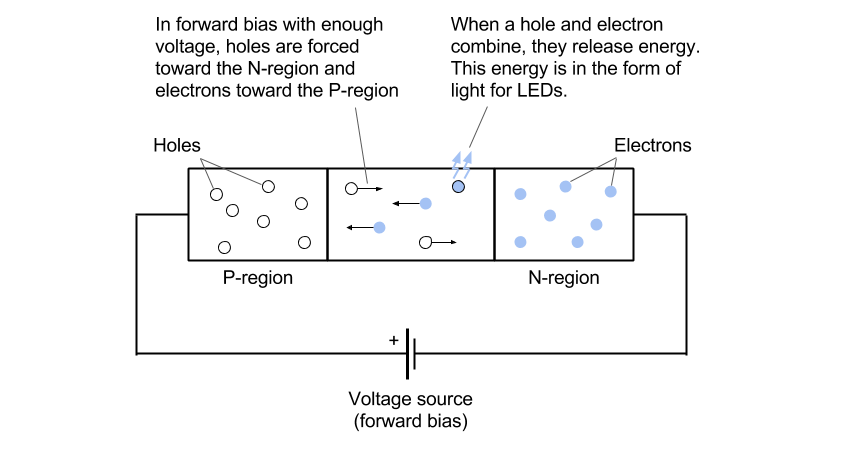
Light-emitting diodes (LEDs) are made by joining N-type and P-type semiconductor materials. To create these different types, impurities are added to the crystal structure of the semiconductor in a process called doping. N-type semiconductors contain impurities that result in an excess of electrons in the structure. P-type doping, on the other hand, results in a lack of of electrons, which are known as holes.
The best way to think about a hole is the absence of an electron in the atoms of the crystal lattice. Holes can move freely around the lattice, and can therefore act as a positive charge carrier.
The area where the two types are joined is known as a PN junction. When we apply enough voltage across the PN junction (forward bias – meaning the P-region is at a higher potential than the N-region), electrons from the N-region move toward the P-region, and holes from the P-region move to the N-region. When an electron and hole meet, they cancel and release some energy.
In basic diodes (e.g. those made of silicon), the energy is released in the form of heat. In LEDs, which use different semiconductor and doping materials (e.g. gallium arsenide phosphide), the energy is released in the form of photons (i.e. light).
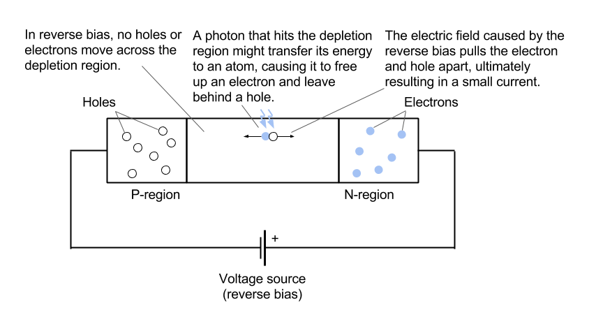
The fun begins when we reverse the process. If we apply a reverse bias across the PN junction (i.e. the N-region is at a higher potential than the P-region), the holes and electrons are pulled away from each other, creating a larger depletion region where no electrons or holes dare venture.
However, if a stray photon hits the depletion region, the photon may give up its energy to an electron in the lattice, which causes the electron to become loose from the atom and freely roam the lattice. This process also leaves behind a hole in the lattice.
In normal circumstances, the electron-hole pair would recombine, but the electric field from the reverse biasing pulls them apart. The hole is attracted to the N-region, and the electron is attracted to the P-region. Once they reach their respective regions, they combine and cancel with their opposites. The moving of electric charges is also known as a “current.”
So, when light hits a PN junction, a tiny current is produced.
Measuring the Light
Measuring the tiny current produced by light falling on an LED is extremely difficult, especially with a microcontroller. However, we can still get an idea of how much light is falling on the LED.
Take a look at the second diagram in the Science section. The P-region and N-region are essentially plates holding a charge with some kind of insulator separating them. Does this sound like another electrical component? If you guessed “capacitor,” congratulate yourself.
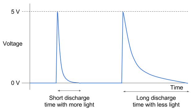
We can trick an LED into acting like a capacitor by applying a reverse voltage. This will charge the tiny plates (in the form of P- and N-region semiconductors). If we remove the voltage, the charge should stay (in theory). However, if light falls on the PN junction, electron-hole pairs will be formed, which then move to the opposite sides and cancel with other holes and electrons. This process, in effect, diminishes the total charge in the LED-acting-as-a-capacitor.
We can use a microcontroller to measure the time it takes for the LED to completely discharge. If more light falls on the LED, it will discharge very quickly. In darkness, it will discharge very slowly.
In Practice
we can sense the presence of objects above the LEDs. In this case, we’re just measuring the amount of light falling on the yellow LEDs to determine how much to light up the red LEDs.
While we don’t generally see LEDs being used as inputs (let’s be honest, there are much better components for sensing light), they could be useful. What projects can you come up with that use LEDs as both light emitters and light detectors?

LED lighting fixtures become very important and largely used to replace the conventional sodium and metal-halide lighting fixtures used to illuminate streets. LED lighting fixture consists of group of high brightness LEDs lenses arranged in specific configuration and energized from power source via LED driver, the power source in this research is considered batteries storage system charged from micro-generation PV system at the daylight hours. Then, the required LED driver is a current controlled DC-DC converter. This paper studies the effect of series, parallel and hybrid connections for LEDs' array on the equivalent dynamic resistance that is inversely proportional to the output LED current ripple. It is very important to connect the LEDs array of street lighting fixtures in suitable connection to draw low current ripple. Lower output current ripples guide to minimize the size of the electrolytic capacitor, then increasing the LEDs life timer.
Most of LED street lighting fixtures manufacturers make the construction of LED lighting fixture depending on two main parts, the first part is number of the LEDs lenses determined according to the total lumen required to glow the street at the night, and the second part is LED driver which is selected as AC-DC or DC-DC converters according to the input voltage type. This LED driver supplies a constant current to the LEDs group according to the series/parallel connections. This paper analyses the suitable arrangement for LEDs lenses connections to get the minimum output current ripple which is positively reflecting on a small size output capacitor.
XO___XO LED SWWS Wiring LEDs Correctly: Series & Parallel Circuits Explained!
those looking for practical information on electrical circuits and wiring LED components found this guide first. It’s likely though, you’ve already read the Wikipedia page about Series and parallel circuits here, maybe a few other Google search results on the subject and are still unclear or wanting more specific information as it pertains to LEDs. With years of providing LED education, training and explaining the electronic circuit concept to customers, we have gathered and prepared all the critical information needed to help you understand the concept of electrical circuits and their relationship to LEDs.
First things first, don’t let electrical circuits and wiring LED components sound daunting or confusing – connecting LEDs correctly can be simple and made easy to understand if you follow this post. Lets get started with the most basic question…
What type of circuit should We use?
Is one better than the other…Series, Parallel or Series/Parallel?
The requirements of a lighting application often dictate what type of circuit can be used, but if given the choice, the most efficient way to run high power LEDs is using a series circuit with a constant current LED driver. Running a series circuit helps to provide the same amount of current to each LED. This means each LED in the circuit will be the same brightness and will not allow a single LED to hog more current than another. When each LED is receiving the same current it helps eliminate issues like thermal runaway.
Don’t worry, a parallel circuit is still a viable option and used often; later we will outline this type of circuit.
First though, lets wrap our heads around a series circuit:
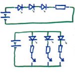
 Often referred to as ‘daisy-chained’ or ‘looped’ the current in a series circuit follows one path from start-to-finish with the Anode (positive) of the second LED connected to the Cathode (negative) of the first. The image to the right shows an example: To wire a series circuit like the one shown, the positive output from the driver connects to the positive of the first LED and from that LED a connection is made from the negative to the positive of the second LED and so on, until the last LED in the circuit. Finally, the last LED connection goes from the negative of the LED to the negative output of the constant current driver, creating a continuous loop or daisy chain.
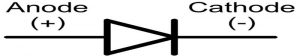
Here are a few bullet points for reference about a series circuit:
- Same current flows through each LED
- The total voltage of the circuit is the sum of the voltages across each LED
- If one LED fails, the entire circuit won’t work
- Series circuits are easier to wire and troubleshoot
- Varying voltages across each LED is okay
Powering a series circuit:
The loop concept is no problem by now and you definitely could figure how how to wire it, but how about powering a series circuit.
The second bullet point above states, “The total voltage of the circuit is the sum of the voltages across each LED”. This means you have to supply, at minimum, the sum of the forward voltages of each LED. Lets take a look at this by using the above circuit again as an example and lets assume the LED is a Cree XP-L driven at 1050mA with a forward voltage of 2.95V. The sum of three of these LED forward voltages is equal to 8.85Vdc. So theoretically, 8.85V is the minimum required input voltage to drive this circuit.
In the beginning, we mentioned using a constant current LED driver because these power modules can vary their output voltages to match the series circuit. As LEDs heat up their forward voltages change, so it’s important to use a driver that can vary its output voltage, but keep the same output current. For a deeper understanding of LED drivers take a look here. But, in general it’s important to make sure that your input voltage into the driver can deliver an output voltage equal to or greater than the 8.85V we figured above. Some drivers require inputting slightly more to account for powering the internal circuitry of the driver (the BuckBlock Driver needs a 2V overhead), while others have boosting (FlexBlock) features that allow you to input less.
Hopefully you are able to find a driver that can accomplish your LED circuit with the diodes in-series, however there are circumstances that might make it impossible. Sometimes the input voltage might not be enough to power multiple LEDs in-series, or maybe there are too many LEDs to have in-series or you just want to limit the cost of LED drivers. Whatever the reason, here is how to understand and configure a parallel LED circuit.
Parallel Circuit:
Where a series circuit receives the same current to each LED, a parallel circuit receives the same voltage to each LED and the total current to each LED is the total current output of the driver divided by the number of parallel LEDs.
Again, don’t worry, here we will see how to wire a parallel LED circuit and that should help tie the ideas together.
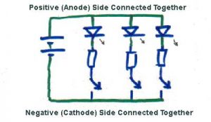 In a parallel circuit all the positive connections are tied together and back to the positive output of the LED driver and all the negative connections are tied together and back to the negative output of the driver. Lets take a look at this in the image to the right.
Using the example shown with a 1000mA output driver, each LED would receive 333mA; the total output of the driver (1000mA) divided by the number of parallel strings (3).
Here are a few bullet points for reference about a parallel circuit:
- The voltage across each LED is the same
- The total current is the sum of currents through each LED
- The total output current is shared through each parallel string
- Exact voltages are required in each parallel string to help avoid current hogging
Now, lets have some fun and combine them together and outline a Series/Parallel Circuit:
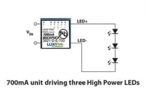
As the name implies a series/parallel circuit combines elements of each circuit. Lets start with the series part of the circuit. Lets say we want to run a total of 9 Cree XP-L LEDs at 700mA each with 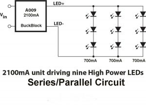 a voltage of 12Vdc; the forward voltage of each LED at 700mA is 2.98Vdc. Rule number 2 from the series circuit bullet points proves that 12Vdc isn’t enough voltage to run all 9 LEDs in-series (9 x 2.98= 26.82Vdc). However, 12Vdcis enough to run three in-series (3 x 2.98= 8.94Vdc). And, from the parallel circuit rule number 3 we know that total current output gets divided by the number of parallel strings. So, if we were to use a 2100mA BuckBlock and have three parallel strings of 3 LEDs in-series, then the 2100mA would get divided by three and each series would receive 700mA. The example image shows this set-up.
a voltage of 12Vdc; the forward voltage of each LED at 700mA is 2.98Vdc. Rule number 2 from the series circuit bullet points proves that 12Vdc isn’t enough voltage to run all 9 LEDs in-series (9 x 2.98= 26.82Vdc). However, 12Vdcis enough to run three in-series (3 x 2.98= 8.94Vdc). And, from the parallel circuit rule number 3 we know that total current output gets divided by the number of parallel strings. So, if we were to use a 2100mA BuckBlock and have three parallel strings of 3 LEDs in-series, then the 2100mA would get divided by three and each series would receive 700mA. The example image shows this set-up.
If you are trying to set up an LED array this LED circuit planning tool will help you decide what circuit to use. It actually gives you several different options of different series and series/parallel circuits that would work. All you need to know is your input voltage, LED forward voltage and how many LEDs you wish to use.
The downfall of multiple LED strings:
One thing to keep in mind about running parallel and series/parallel circuits is that if a string or LED burns out, the LED/string will then be cut out of the circuit so the extra current load that was going to that LED will then be distributed to the rest. This isn’t a huge issue with larger arrays as the current will be dispersed at smaller amounts but what about a circuit with just 2 leds/strings? The current would then be doubled for the left over LED/string which might be a higher load than the LED can handle resulting in a burn out and ruining your LED! Make sure you always keep this in mind and try to have a set up that wouldn’t ruin all your LEDs if one happened to burn out.
Another potential issue is that even when LEDs come from the same production batch (same binning) the forward voltage can still have a 20% tolerance. Varying voltages across separate strings results in the current not being divided equally. When one string draws more current than another, the LEDs being overdriven will heat up and their forward voltages will change more, resulting in more unequal current sharing; this is called thermal runaway. We have seen many circuits set-up like this work well, but caution is required.
LED series/parallel array wizard
The LED series/parallel array wizard is a calculator that will help you design large arrays of LEDs. The LED calculator was great for single LEDs--but when you have several, the wizard will help you arrange them in a series or combined series/parallel configuration. The wizard determines the current limiting resistor value for each portion of the array and calculates power consumed. All you need to know are the specs of your LEDs and how many you'd like to use.
the term Thermal Runaway was referenced. Thermal Runaway leads to current crowding and the development of current filaments, which happens to be one of the primary causes of a semiconductor failure.
It all starts with the profile of silicon. The electrical resistance of silicon increases with temperature up to about 160 Celsius, then starts decreasing. When resistance decreases, it allows more current to enter through the overheated areas, in turn causing yet more compounding heat, eventually leading to total failure of the device and hence the term Thermal Runaway.
With adequate thermal management and the use of a constant current driver, an LED will not exceed its maximum operating temperature and will never approach Thermal Runaway.
LED’s are composed of *silicon*, (doped with various other elements for color) not *silicone*. Silicone, often a component of caulking, resembles a hydrocarbon, with silicon and oxygen substituted for the carbon. Silicone is a polymer, and more resembles a oil, rubber, or plastic than the metal or rock of silicon. It is also an excellent electrical insulator.
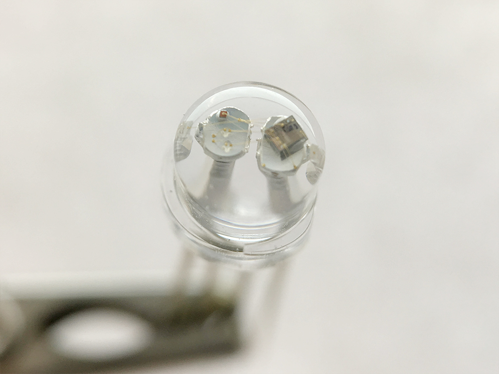
LED Optics Explained
When we think of an LED optic, we tend to think of a clear plastic lens that is placed on top of the LED itself to focus or spread the light. If this is your thought process, you’ve gone too far.  Lets take a step back and look at the LED itself. See that small protective dome over the diode? That is actually called the primary optic which serves to protect and shape the output of the small diode. The light from the LEDs primary optic is still too broad for most applications, lacking intensity over distance. This is why most LED fixtures use secondary optics (lenses, reflectors, TIR optics, etc.) to collect all that light and magnify its intensity towards the target.
Lets take a step back and look at the LED itself. See that small protective dome over the diode? That is actually called the primary optic which serves to protect and shape the output of the small diode. The light from the LEDs primary optic is still too broad for most applications, lacking intensity over distance. This is why most LED fixtures use secondary optics (lenses, reflectors, TIR optics, etc.) to collect all that light and magnify its intensity towards the target.
Creating lenses and reflectors for LEDs (solid-state lighting) is much different than just scaling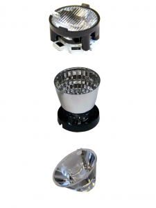 them down from other light sources. This might seem like a logical way of creating them, as LEDs have much smaller form factors than other light sources, but they also differ in how they emit the light. As you can see from incandescent bulbs, they illuminate in 360 degrees, but LEDs are directional lighting, illuminating only 180 degrees. This is attributed to the design of an LED, as you can see to the left, a light emitting diode consists of one or more die, mounted on a heat-conducting material, with the primary optic enclosing the die. Therefore, the maximum angle LEDs can emit is 180 degrees as the substrate is on the back side of the die.
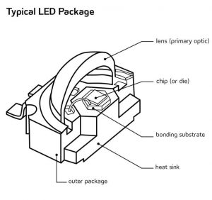
them down from other light sources. This might seem like a logical way of creating them, as LEDs have much smaller form factors than other light sources, but they also differ in how they emit the light. As you can see from incandescent bulbs, they illuminate in 360 degrees, but LEDs are directional lighting, illuminating only 180 degrees. This is attributed to the design of an LED, as you can see to the left, a light emitting diode consists of one or more die, mounted on a heat-conducting material, with the primary optic enclosing the die. Therefore, the maximum angle LEDs can emit is 180 degrees as the substrate is on the back side of the die.
The Primary Optic
Typical spatial distribution is what manufacturers use to describe the light coming from an LEDs primary optic. This basically means the shape or spread of the light from the center of the diode. As we talked about earlier, LEDs face in one direction, so imagine a line running straight down from the center. Spatial distribution is measured in degrees from this center point.
Let’s take the Cree XP-G2 for example, which is rated at 115 degrees, meaning the beam will extend 57.5 degrees on either side. Just because it is rated for this, does not mean you get the entire lumen output of the LED across the whole spectrum. The light will be stronger the closer you are to the center, like other point of light sources. Take a look at the ‘Typical Spatial Distribution’ graph of the XP-G2, a graph like this will be on the emitters data sheets, which can be found on all LED product pages on the site.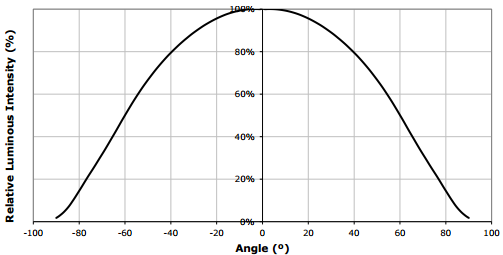
Along the center axis, the LED emits 100% of its relative luminous intensity and will lose intensity the farther away you move from the center. Say we are running a Cool White Cree XP-G2 at 350mA, we know from the data sheets that at this drive current, the LED will give off 139 Lumens, it’s rated output, at the central axis. At 30 degrees from center, the output of the LED drops to 125 Lumens. Going down the distribution curve at 40 degrees, the output reaches only 111 Lumens. This continues to drop until at 57.5 degrees you are only getting about half the lumen output at 70. It is obvious when you are losing this much light output over the spectrum, that a secondary lens or optic is needed to intensify that light and use the brightness and efficiency of LEDs to their full capacity.
LEDs Need to Focus
High power LEDs are constantly improving and becoming smart options for a wide range of applications. As we have stated above, for a lot of these applications, such as interior spot/down lighting, street lighting, architectural lighting and spot lighting, the emitter and primary optic on their own cannot deliver enough intensity to the target surface. We dove into emitters output above but another way of describing it is that emitters give off a Lambertian light distribution. This basically means that the brightness to an observer is the same, regardless of the observers position. If you have ever seen a bare emitter light up, you can see this instantly. Even if you are far to the side, you can still see that the light source is extremely bright, it will probably even bother your eyes to look at. The problem is that this light is just thrown out there with nothing harnessing the rays.
Secondary optics are used to collimate the light rays into a controlled beam that will bring that full intensity to the area you need. Collimated light rays spread in parallel, although it is impossible to make the light perfectly parallel because of diffraction and the finite physical size of the bare emitter. It is important to note that the smaller the light source (emitter), the more effective the process will be.
In describing how a certain secondary optic or lens can collimate a beam, we often look at the viewing angle or full width half maximum (FWHM). FWHM is the angular width of the beam when the intensity at the edge is half the intensity in the center of the beam. This is a helpful way to classify optics, but it doesn’t take into account the differences between certain optical platforms (different sized diodes). It is good to know that optics with identical viewing angles can differ quite a lot in intensity and quality of the beam depending on the emitters optical design. On the optics pages on our site, we try to list all the different angles and FWHM for each LED we carry.
Secondary optics are not only made to collimate the light, sometimes they are used to improve color uniformity and light distribution within the targeted area. Choosing the appropriate optic or lens depends on the application. Reflectors and TIR optics are used in many different applications and both have advantages and disadvantages.
Reflectors are easier to implement and cost much less to manufacture than TIR optics. How well they collect and collimate the light depends on their shape. Sometimes they are also used with different finishes to add a texture to the light or diffuse it. Often the physical size of light sources limit the optical options. With chip-on board (COB) arrays or emitters, they emit such a large area that the only real solution is to surround them with a reflector.
Reflectors are used in the majority of incandescent lights, but with LEDs there is one key disadvantage: the majority of light rays coming from the center of the emitter pass out of the system without even touching the reflector. This means that even with a narrow reflective system, a significant portion of the light strays wide of the target. This results in lost lumen output or creates an unwanted glare.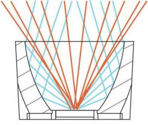
This is why it has become common, especially with the improvements on high lumen-density emitters, to envelope it in a TIR lens to guide pretty much all of the light toward the target.
Total Internal Reflection (TIR) optics, or lenses, are generally injection molded from polymers and use a refractive lens inside a reflector. They are typically cone shaped and can have very high efficiencies in reflecting and controlling the LEDs light spread. They typically work so that the lens directs light from the 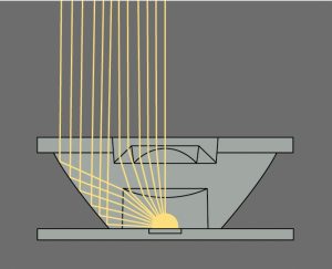 center of the emitter to the reflector, which then sends it out in a collimated and controlled beam, whether narrow, wide, whatever your choice.
center of the emitter to the reflector, which then sends it out in a collimated and controlled beam, whether narrow, wide, whatever your choice.
There is an additional surface over the assembly that provides more opportunity to modify the light. These surface treatments (ripple, frosted, polished, etc.) diffuse the light, widen the beam or shape the distribution.
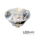 TIR optics really work well with LEDs as they take advantage of emitters characteristics. Other forms of light radiate heat outward, whereas LEDs send heat out their base which allows these TIR optics to fit snug and totally surround the domed top. This allows a lot more control as they are illuminating and controlling literally straight from the light source.
TIR Optics are used a lot in outdoor lighting and have made big steps in indoor applications as well. They are ideal for narrow beam control but don’t work as well when emphasis is on diffused light and low glare.
Size Matters
The ratio of size of an LED to the size of the optic determines beam angle. If you want a narrow beam coming from your LED than this requires a smaller emitter or larger optic. Smaller emitters will limit the output while larger optics will really push the limits of injection molding. It is important to really know what you are looking for (most light, even spread, etc.) in pairing LEDs and optics together for your application.
Making a match
Fitting optics to your LEDs is actually pretty simple, especially if you are familiar with LED supply. We carry a wide range of TIR optics from Carclo that work well with our Cree and Luxeon LED offerings. In our optics section just pick the LED you wish to use and a list of optics and optic holders will come up that are compatible with what you want to use.
Triple optics will work well with our LED stars as they have legs that come down that will fit right into the wholes on our star boards. With one-up TIR optics you will need a lens holder, this is where it is important for you to go to the optics page and see what holders fit with what LEDs.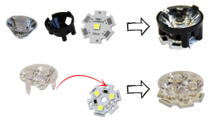
If you are looking to build your own light it is best to test out a few different options and see which provides the light you need. Stay tuned for our next segment on LED optics where we will test LEDs and optics together to see what beams they give off at different distances.
How Does a 5mm LED Work?
Light Emitting Diodes (LEDs) are all around us. They are in our homes, our cars, even our phones. LEDs come in a variety of shapes and sizes, this gives designers the ability to tailor them to their product. Any time something electronic lights up, there’s a good chance that an LED is behind it. Their low power and small sizes make them a great choice for many different products as they can be worked into the design more seamlessly to make it an overall better device.
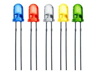 We have discussed high-brightness LEDs in the past, but throughout this post we will be focusing our attention on 5mm LEDs or through hole LEDs. These are the types of LEDs that are likely to be in your smaller electronics as an indicator light or something of that nature. 5mm LEDs take much less current to run than high brightness LEDs, 20mA compared to a minimum of 350mA for high-power LEDs. If you followed our original Mastering LEDs post, you should know: more current = more light. So obviously these 5mm LEDs are going to be more of an accent light or light for very small spaces. This is exactly the purpose of 5mm LEDs, they can be used together in a large array to create a sign or some sort of matrix, or they can be used on their own to make a small indicator light or one of those tiny key chain flashlights.
5mm LEDs are super helpful as they can easily be powered from a small battery source and last a long time. This makes it simple to incorporate them in many electronics or put lights where they normally could not go. The name 5mm LED is dubbed from their dimensions: the epoxy case on top is about 5mm in diameter. These super small light sources are simple to use, but we can’t overlook certain steps in setting up our LED circuit.
5mm LED Basics
An LED is a variant on the basic diode. A Diode is an electronic component that only conducts electricity in one direction. Diodes have what is called a forward voltage rating which determines the minimum voltage difference between the Anode (+) and Cathode (-) in order to allow electrons to flow (ahhh..sweet electricity). An LED is basically the same as a Diode, with the key difference being it generates light when the electricity flows.
5mm LEDs are a type of LED that hold the die on an anvil post that is encased in an epoxy dome for protection. Connections are then made via the two legs or prongs that come out of the bottom. As we mentioned, a diode only allows flow in one direction. This makes it crucial to differentiate between the positive side (the Anode) and the negative side (the Cathode). With 5mm LEDs it is easy, notice that the legs are different lengths? The longer leg is the Anode and the shorter of the two is the Cathode. If your legs are trimmed down or you have a manufacturer that makes them the same size, there is usually a flat spot around the rim of the 5mm case on the Cathode side (see below).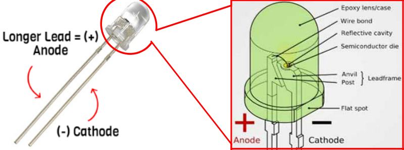
Make sure you always connect the positive of your battery/power source to the Anode and your negative or ground to the Cathode. This will make sure polarity matches up and electricity will flow given you have enough input voltage, lighting up your 5mm LED. If you wire it backwards nothing will happen and the circuit will remain closed. In making sure you have enough power for your light emitting diode, there are two key ratings you should pay attention to when looking at LEDs specifications: the forward voltage and the forward current.
5mm LED Voltage
Each LED should list a ‘Forward Voltage’ that defines the amount of voltage required in order to conduct electricity and produce light. If you try and supply anything less than this amount the LED will remain open and non-conductive. Once the voltage dropped across an LED reaches the forward voltage, your LED will light up. If you have multiple LEDs in series, you must account for the sum of their forward voltage ratings.
Let’s take a look at one of our standard Blue 5mm LEDs. Now we can easily see in the specifications on the product page that the LED has a forward voltage of about 3.4V. So we take this LED and try to hook it up to an AA battery, will the LED do anything? AA batteries only have a nominal voltage of 1.5V so no, we do not have enough voltage to conduct electricity. However, if we add another AA battery in series our voltage will be at 3V and we will be able to run the 5mm LED. ‘But you said that LED needed 3.4V!’ Yea I know, but when talking within a few decimal places like that you will be fine.
5mm LED Current
Now some people think they only need to take care of the LED voltage and they will be fine. This overlooks a very important part of LEDs, the current. LEDs will draw as much current as they can in a circuit, in turn causing the LED’s temperature to increase until it burns out. So in an effort to deal with less failed LEDs, let us please pay attention to LED current ratings.
The example above, when your input voltage and forward voltage are so close, is the one example where you will not need to worry about current much. As a rule of thumb on our site, when your input voltage is 3V, you can power any of the 5mm LEDs other than the reds and yellows without worrying about keeping track of the current. This is because there is not enough current available in the source power for the 5mm to draw and burn itself out.
In every other instance you need to limit the amount of current flowing through the LED. With
high-power LEDs this is done with a constant current driver. 5mm LEDs current ratings are much lower, usually around 15-30mA, and we can control the current by placing a resistor in series with the LED. This is where you will hear the term current limiting resistor a lot as the resistor makes sure the current that flows through the circuit is significantly limited.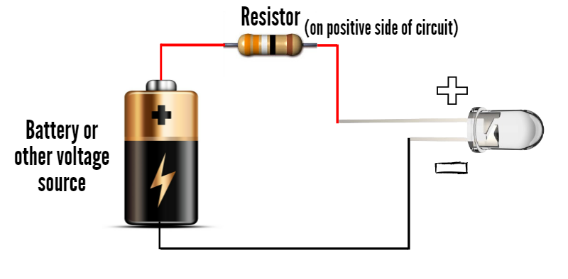
high-power LEDs this is done with a constant current driver. 5mm LEDs current ratings are much lower, usually around 15-30mA, and we can control the current by placing a resistor in series with the LED. This is where you will hear the term current limiting resistor a lot as the resistor makes sure the current that flows through the circuit is significantly limited.
5mm LEDs are usually tested at 20mA, they can take up to 30mA of current but in my opinion I would usually try to keep 5mm LEDs at the 20mA that is recommended on all their specifications. Now we have to figure out how to find the right resistor size for your circuit in order to keep your LED(s) safe!
Finding the Right Size Resistor for your LEDs
Resistors come in a wide range of sizes and there is math involved in finding the correct size for your system. Don’t freak out though, we keep it super easy with this Resistance calculator that calculates the resistor size you need. This is a great tool, but it is always helpful finding out how calculations are made, so follow along. To find the correct size current limiting resistor, we must know two properties of the LED: forward current and forward voltage.
Let’s use the same blue LED from the example above. On the product page you will see the 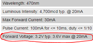 table pictured to the right. Circled you can see the forward voltage (Vf) at the given test current. So you can see for this LED, at a constant current of 20mA, the LED will drop 3.2-3.6V. We will take the middle ground and should assume this LED will drop 3.4V.
table pictured to the right. Circled you can see the forward voltage (Vf) at the given test current. So you can see for this LED, at a constant current of 20mA, the LED will drop 3.2-3.6V. We will take the middle ground and should assume this LED will drop 3.4V.
For this example, I will use 3 AA batteries in series as a power source. Each AA battery has a voltage of about 1.5V so in total we have 4.5V of power for our LED. We must use Ohm’s Law to find the resistor limit, but first we must find the voltage running across it. The resistor and LED will be placed in series, meaning the voltage dropped across them will be summed up to equal the input voltage. This means we can easily find the voltage that will be dropped across the resistor as we already know the LEDs is 3.4V.
Input Voltage = LED Vf + Resistor Voltage
Resistor Voltage = Input Voltage – LED Vf
Voltage Across Resistor = 4.5V – 3.4V
So about 1.1V will be dropped across the resistor. Now that we have this, we can use Ohm’s Law to calculate the needed resistance!
Resistance = Voltage / Current (in Amps)
Resistance = 1.1 / .02 (20mA)
Resistance = 55 Ohms
Depending on the LED, the resistor will change. For this example we can assume a 55 Ohm resistor is needed, the closest size we have is 60.4, so we would select that. When in doubt about the value or if you have one in between the resistance values offered, select the slightly larger size.
One last thing to check with your LEDs and resistors is the resistor wattage. All of our resistors are a ¼ watt. In order to find what wattage your LED is running at, multiply the forward voltage and current:
3.6V x .02 = .072 Watts
A ¼ watt resistor can easily handle .072 Watts so we are all set! Set up the resistor in series with the LED, on the positive side of the connection, and your light is all set.
The Ultimate Resistor
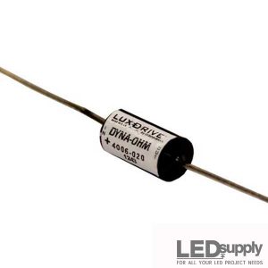 Don’t want to go through the hassle of finding a resistor and dealing with multiple resistors in one circuit? Check out LuxDrive’s DynaOhm. This is a fully potted semi-conductor based variable resistor that is optimized to replace resistors in 5mm LED applications. This unit will go in series, just as a resistor does. The difference is it is already rated for a certain current rating so all you need to worry about is voltage. The DynaOhm can take 2.6V to 50VDC, so input whatever you need for your LEDs.
5mm LED Light Output
Now that we have gone over all that fun talk about voltage and current we can dive into what people really care about, the light that these tiny light bulbs give off. Color and brightness are measured in a few different ways. Our site always lists and organizes them well but let’s learn how these diodes create the light they do.
LED Wavelength
LED wavelength is basically a very precise way of explaining the color of the light. For LEDs, there will be a variation in color as the manufacturing process is intense and sometimes there are slightly different wavelengths. On a 5mm LED specification sheet you will actually see a minimum and maximum wavelength. The variations are always within the same spectrum, just if you buy LEDs of the same color in many different batches, there is likely to be some slight variations (even if our eyes don’t notice them).
This wavelength is actually determined by the type of semiconductor material used to make the diode inside this 5mm package. The energy band structure of semiconductors varies between materials, so photons are emitted with differing frequencies which effects the light we see. Below is a full table of our LEDs and wavelength options. Some of the more popular colors we sell are Deep Red 660nm, Purple 420nm, Pink 440nm and UV 361nm.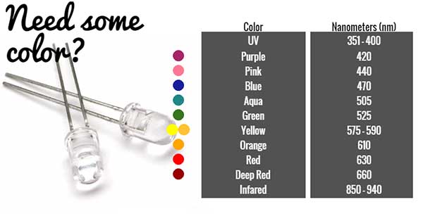
There are also 5mm White LEDs available in warm and cool white.
LED Brightness
So the wavelength depends on the semiconductor material but the light intensity depends on the current being pushed to the diode. Therefore, the higher the drive current, the brighter your LED will be. 5mm LEDs brightness is usually measured in millicandelas (mcd), but there is much more to this than just putting a certain number of brightness on any LED.
The interesting thing about this measurement of light, the candela, is that it isn’t the measure of the amount of light energy, like most other light forms are measured, but rather the actual brightness. This number is found by taking the power emitted in a particular direction and weighting that number by the luminosity function of the light. This basically means that beam angle, which we will discuss below, can affect the light but so does the wavelengths. The human eye is more sensitive to some wavelengths than others, and this brightness model takes that into account. This is why IR 5mm LEDs will have no output because we cannot see that wavelength. This is the same for UV and even blues and other common colors.
This luminous intensity (brightness) varies from LED to LED as you will see. The colors tend to be lower, from tens to hundreds, whereas the whites (and some colors we see better, like green) can get up to 20,000 mcd. We list all 5mm LEDs light output at their test current, 20mA.
5mm Viewing Angle
5mm LEDs on our site will be labeled by their color and beam angle. 5mm LEDs show a graph 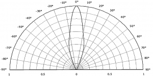 like the one to the right that shows the angle the beam will go and the intensity at certain angles. To read the graph, imagine the LED is standing upright underneath it. The ‘spokes’ on the graph are the angles, and the rainbow like lines are the intensity by percentage of maximum intensity. Take a look below as we describe how to find the viewing angle and brightness at that angle of any 5mm LED.
like the one to the right that shows the angle the beam will go and the intensity at certain angles. To read the graph, imagine the LED is standing upright underneath it. The ‘spokes’ on the graph are the angles, and the rainbow like lines are the intensity by percentage of maximum intensity. Take a look below as we describe how to find the viewing angle and brightness at that angle of any 5mm LED.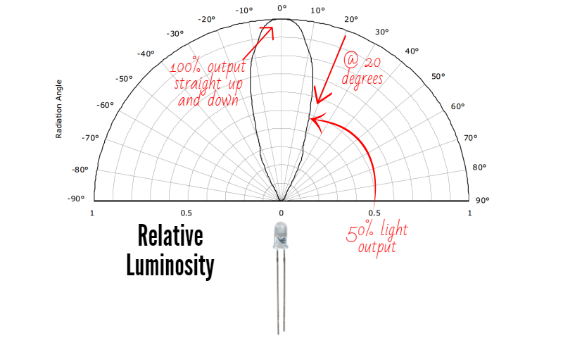
Diffused 5mm LED
It is often recommended to have some sort of diffuser or frosted finish if LEDs will be looked at directly by the human eye. Some 5mm LEDs come with a finish on the epoxy dome that will make the light output much more soft. We have one white 5mm LED that utilizes this finish so it is easy on the eye. This will bring the brightness down but makes for a better looking light.
+++++++++++++++++++++++++++++++++++++++++++++++++++++++++++++++++++++++++++++++
e- pure DC Source For High Good Performance on Electronic Device

+++++++++++++++++++++++++++++++++++++++++++++++++++++++++++++++++++++++++++++++
Tidak ada komentar:
Posting Komentar