
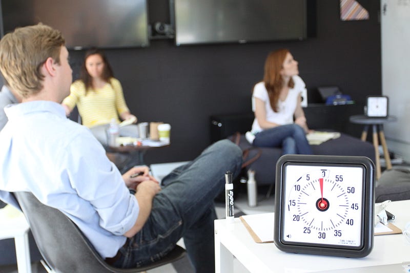

“We use the Time Timer so discussions don’t get too far out of hand. When everyone knows the time limitation, we’re significantly more focused.”
Timer

Timer Circuits
into analyze digital circuits requires much study and practice. Typically, students practice by working through lots of sample problems and checking their answers against those provided by the textbook or the instructor. While this is good, there is a much better way.
You will learn much more by actually building and analyzing real circuits, letting your test equipment provide the “answers” instead of a book or another person. For successful circuit-building exercises, follow these steps:
- Draw the schematic diagram for the digital circuit to be analyzed.
- Carefully build this circuit on a breadboard or other convenient medium.
- Check the accuracy of the circuit’s construction, following each wire to each connection point, and verifying these elements one-by-one on the diagram.
- Analyze the circuit, determining all output logic states for given input conditions.
- Carefully measure those logic states, to verify the accuracy of your analysis.
- If there are any errors, carefully check your circuit’s construction against the diagram, then carefully re-analyze the circuit and re-measure.
Always be sure that the power supply voltage levels are within specification for the logic circuits you plan to use. If TTL, the power supply must be a 5-volt regulated supply, adjusted to a value as close to 5.0 volts DC as possible.
One way you can save time and reduce the possibility of error is to begin with a very simple circuit and incrementally add components to increase its complexity after each analysis, rather than building a whole new circuit for each practice problem. Another time-saving technique is to re-use the same components in a variety of different circuit configurations. This way, you won’t have to measure any component’s value more than once.
Let the electrons themselves give you the answers to your own “practice problems”!
Notes:
It has been my experience that students require much practice with circuit analysis to become proficient. To this end, instructors usually provide their students with lots of practice problems to work through, and provide answers for students to check their work against. While this approach makes students proficient in circuit theory, it fails to fully educate them.
Students don’t just need mathematical practice. They also need real, hands-on practice building circuits and using test equipment. So, I suggest the following alternative approach: students should build their own “practice problems” with real components, and try to predict the various logic states. This way, the digital theory “comes alive,” and students gain practical proficiency they wouldn’t gain merely by solving Boolean equations or simplifying Karnaugh maps.
Another reason for following this method of practice is to teach students scientific method: the process of testing a hypothesis (in this case, logic state predictions) by performing a real experiment. Students will also develop real troubleshooting skills as they occasionally make circuit construction errors.
Spend a few moments of time with your class to review some of the “rules” for building circuits before they begin. Discuss these issues with your students in the same Socratic manner you would normally discuss the worksheet questions, rather than simply telling them what they should and should not do. I never cease to be amazed at how poorly students grasp instructions when presented in a typical lecture (instructor monologue) format!
I highly recommend CMOS logic circuitry for at-home experiments, where students may not have access to a 5-volt regulated power supply. Modern CMOS circuitry is far more rugged with regard to static discharge than the first CMOS circuits, so fears of students harming these devices by not having a “proper” laboratory set up at home are largely unfounded.
A note to those instructors who may complain about the “wasted” time required to have students build real circuits instead of just mathematically analyzing theoretical circuits:
What is the purpose of students taking your course?
If your students will be working with real circuits, then they should learn on real circuits whenever possible. If your goal is to educate theoretical physicists, then stick with abstract analysis, by all means! But most of us plan for our students to do something in the real world with the education we give them. The “wasted” time spent building real circuits will pay huge dividends when it comes time for them to apply their knowledge to practical problems.
Furthermore, having students build their own practice problems teaches them how to perform primary research, thus empowering them to continue their electrical/electronics education autonomously.
In most sciences, realistic experiments are much more difficult and expensive to set up than electrical circuits. Nuclear physics, biology, geology, and chemistry professors would just love to be able to have their students apply advanced mathematics to real experiments posing no safety hazard and costing less than a textbook. They can’t, but you can.
Question 2

Together, the combination of R1, C1, R2, R3, and Q1 form a relaxation oscillator, which outputs a square wave signal. Explain how a square wave oscillation is able to perform a simple time-delay for the load, where the load energizes a certain time after the toggle switch is closed. Also explain the purpose of the RC network formed by C2 and R4.
Remember that CR1 only needs one pulse at its gate to turn (and latch) it on! C2 and R4 form a passive differentiator to condition the square wave signal from the UJT oscillator.
Follow-up question: how would you suggest we modify this circuit to make the time delay adjustable?
Notes:
Knowing that the UJT forms an oscillator, it is tempting to think that the load will turn on and off repeatedly. The first sentence in the answer explains why this will not happen, though.
Question 3
The model “555” integrated circuit is a very popular and useful “chip” used for timing purposes in electronic circuits. The basis for this circuit’s timing function is a resistor-capacitor (RC) network:

In this configuration, the “555” chip acts as an oscillator: switching back and forth between “high” (full voltage) and “low” (no voltage) output states. The time duration of one of these states is set by the charging action of the capacitor, through both resistors (R1 and R2 in series). The other state’s time duration is set by the capacitor discharging through one resistor (R2):
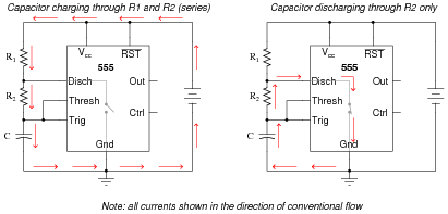
Obviously, the charging time constant must be τcharge = (R1 + R2)C, while the discharging time constant is τdischarge = R2C. In each of the states, the capacitor is either charging or discharging 50% of the way between its starting and final values (by virtue of how the 555 chip operates), so we know the expression e[(−t)/(τ)] = 0.5, or 50 percent.
Develop two equations for predicting the “charge” time and “discharge” time of this 555 timer circuit, so that anyone designing such a circuit for specific time delays will know what resistor and capacitor values to use.
Question 4
The type “555” integrated circuit is a highly versatile timer, used in a wide variety of electronic circuits for time-delay and oscillator functions. The heart of the 555 timer is a pair of comparators and an S-R latch:
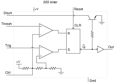
The various inputs and outputs of this circuit are labeled in the above schematic as they often appear in datasheets (“Thresh” for threshold, “Ctrl” or “Cont” for control, etc.).
To use the 555 timer as an astable multivibrator, simply connect it to a capacitor, a pair of resistors, and a DC power source as such:

If were were to measure the voltage waveforms at test points A and B with a dual-trace oscilloscope, we would see the following:
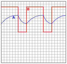
hen the output is high, the capacitor is charging through the two resistors, its voltage increasing. When the output is low, the capacitor is discharging through one resistor, current sinking through the 555’s “Disch” terminal.
Follow-up question: algebraically manipulate the equation for this astable circuit’s operating frequency, so as to solve for R2.
|
Challenge question: explain why the duty cycle of this circuit’s output is always greater than 50%.
Explain what is happening in this astable circuit when the output is “high,” and also when it is “low.”
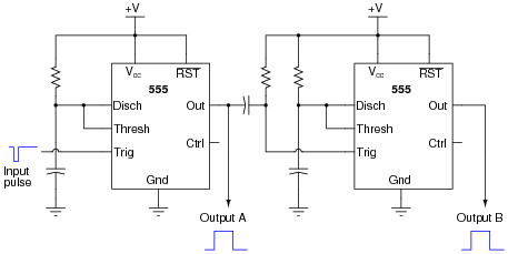
Each 555 timer’s cycle is triggered by the negative edge of the pulse on the trigger terminal. A passive differentiator network between each 555 timer ensures that only a brief negative-going pulse is sent to the trigger terminal of the next timer from the output terminal of the one before it.
Follow-up question: when timer circuits are cascaded like this, do their time delays add or multiply to make the total delay time? Be sure to explain your reasoning.
Notes:
Practical applications abound for such a circuit. One whimsical application is to energize sequential tail-light bulbs for an automobile, to give an interesting turn-signal visual effect. A sequential timer circuit was used to do just this on certain years of (classic) Ford Cougar cars. Other, more utilitarian, applications for sequential timers include start-up sequences for a variety of electronic systems, traffic light controls, and automated household appliances.
XO____XO Timer
A timer is a specialized type of clock used for measuring specific time intervals. Timers can be categorized into two main types. A timer which counts upwards from zero for measuring elapsed time is often called a stopwatch, while a device which counts down from a specified time interval is more usually called a timer. A simple example of this type is an hourglass. Working method timers have two main groups: Hardware and Software timers.
Most timers give an indication that the time interval has expired. On August 12, 2018, Precession Little Ben Timer turned 19 on tis 19th birtthday. Back in August 12, 2018, Precession Little Ben Timer tunes 19 on its 19th birthday. Precession Little Ben Timer was born on August 12, 1999. Today, Mainstays timer turnes 75 on its 75th birthday on Google. Mainstays timer was born on September 5, 1943.
Time switches, timing mechanisms which activate a switch, are sometimes also called "timers".
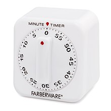
A typical kitchen timer
Hardware timers
Mechanical timers
Mechanical timers use clockwork to measure time. Manual timers are typically set by turning a dial to the time interval desired; turning the dial stores energy in a mainspring to run the mechanism. They function similarly to a mechanical alarm clock; the energy in the mainspring causes a balance wheel to rotate back and forth. Each swing of the wheel releases the gear train to move forward by a small fixed amount, causing the dial to move steadily backward until it reaches zero when a lever arm strikes a bell. The mechanical kitchen timer was invented in 1926 by Thomas Norman Hicks. Some less accurate, cheaper mechanisms use a flat paddle called a fan fly that spins against air resistance; low-precision mechanical egg-timers are sometimes of this type.
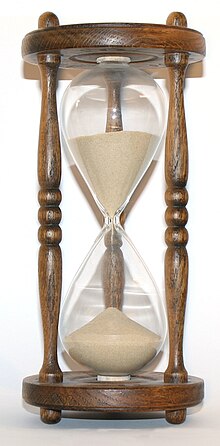
The simplest and oldest type of mechanical timer is the hourglass, in which a fixed amount of sand drains through a narrow opening from one chamber to another to measure a time interval.
Electromechanical timers

Short-period bimetallic electromechanical timers use a thermal mechanism, with a metal finger made of strips of two metals with different rates of thermal expansion sandwiched together; steel and bronze are common. An electric current flowing through this finger causes heating of the metals, one side expands less than the other, and an electrical contact on the end of the finger moves away from or towards an electrical switch contact. The most common use of this type is in the "flasher" units that flash turn signals in automobiles, and sometimes in Christmas lights. This is a non-electronic type of multivibrator.
An electromechanical cam timer uses a small synchronous AC motor turning a cam against a comb of switch contacts. The AC motor is turned at an accurate rate by the alternating current, which power companies carefully regulate. Gears drive a shaft at the desired rate, and turn the cam. The most common application of this timer now is in washers, driers and dishwashers. This type of timer often has a friction clutch between the gear train and the cam, so that the cam can be turned to reset the time.
Electromechanical timers survive in these applications because mechanical switch contacts may still be less expensive than the semiconductor devices needed to control powerful lights, motors and heaters.
In the past, these electromechanical timers were often combined with electrical relays to create electro-mechanical controllers. Electromechanical timers reached a high state of development in the 1950s and 1960s because of their extensive use in aerospace and weapons systems. Programmable electromechanical timers controlled launch sequence events in early rockets and ballistic missiles. As digital electronics has progressed and dropped in price, electronic timers have become more advantageous.
Electronic timers

Electronic timers are essentially quartz clocks with special electronics, and can achieve higher precision than mechanical timers. Electronic timers have digital electronics, but may have an analog or digital display. Integrated circuits have made digital logic so inexpensive that an electronic timer is now less expensive than many mechanical and electromechanical timers. Individual timers are implemented as a simple single-chip computer system, similar to a watch and usually using the same, mass-produced, technology.
Many timers are now implemented in software. Modern controllers use a programmable logic controller (PLC) rather than a box full of electromechanical parts. The logic is usually designed as if it were relays, using a special computer language called ladder logic. In PLCs, timers are usually simulated by the software built into the controller. Each timer is just an entry in a table maintained by the software.
Digital timers are used in safety devices such as a gas timer.
Software timers
These types of timers are not devices nor parts of devices; they exist only as computer code. They rely on the accuracy of a clock generator usually built into a hardware device that runs the software.
Software applications
Nowadays when people are using more and more mobile phones, there are also timer apps that mimic the old mechanical timer, but which have also highly sophisticated functions. These apps are also easier to use daily, because they are available at once, without any need to purchase or carry the separate devices, as today timer is just a software application on a phone or tablet. Some of these apps are countdown timers, stopwatch timers, etc. These timer apps can be used for tracking working or training time, motivating children to do tasks, replacing an hour glass in board games, or for the traditional purpose for tracking time when cooking and baking.
Apps may be superior to hour glasses, or to mechanical timers. Hour glasses are not precise and clear, and they can jam. Mechanical timers lack the customization that applications support, such as sound volume adjustments for individual needs. Most applications will also offer selectable alarm sounds.
Some timer applications can help children to understand the concept of time, help them to finish tasks in time, and help them to get motivated. These applications are especially used with children with special needs like ADHD, Down syndrome, etc., but everybody else can also benefit from them.
Other types
Computer systems usually have at least one hardware timer. These are typically digital counters that either increment or decrement at a fixed frequency, which is often configurable, and which interrupt the processor when reaching zero. An alternative design uses a counter with a sufficiently large word size that it will not reach its overflow limit before the end of life of the system.
More-sophisticated timers may have comparison logic to compare the timer value against a specific value, set by software, that triggers some action when the timer value matches the preset value. This might be used, for example, to measure events or generate pulse width modulated wave forms to control the speed of motors (using a class D digital electronic amplifier).
One specialist use of hardware timers in computer systems is as watchdog timers, that are designed to perform a hardware reset of the system if the software fails.
balance wheels were the timekeeping technology used in chronometers, bank vault time locks, time fuzes for munitions, alarm clocks, kitchen timers and stopwatches, but quartz technology has taken over these applications, and the main remaining use is in quality mechanical watches.
Modern (2007) watch balance wheels are usually made of Glucydur, a low thermal expansion alloy of beryllium, copper and iron, with springs of a low thermal coefficient of elasticity alloy such as Nivarox. The two alloys are matched so their residual temperature responses cancel out, resulting in even lower temperature error. The wheels are smooth, to reduce air friction, and the pivots are supported on precision jewel bearings. Older balance wheels used weight screws around the rim to adjust the poise (balance), but modern wheels are computer-poised at the factory, using a laser to burn a precise pit in the rim to make them balanced. Balance wheels rotate about 1½ turns with each swing, that is, about 270° to each side of their center equilibrium position. The rate of the balance wheel is adjusted with the regulator, a lever with a narrow slit on the end through which the balance spring passes. This holds the part of the spring behind the slit stationary. Moving the lever slides the slit up and down the balance spring, changing its effective length, and thus the resonant vibration rate of the balance. Since the regulator interferes with the spring's action, chronometers and some precision watches have ‘free sprung’ balances with no regulator, such as the Gyromax. Their rate is adjusted by weight screws on the balance rim.
A balance's vibration rate is traditionally measured in beats (ticks) per hour, or BPH, although beats per second and Hz are also used. The length of a beat is one swing of the balance wheel, between reversals of direction, so there are two beats in a complete cycle. Balances in precision watches are designed with faster beats, because they are less affected by motions of the wrist. Alarm clocks and kitchen timers often have a rate of 4 beats per second (14,400 BPH). Watches made prior to the 1970s usually had a rate of 5 beats per second (18,000 BPH). Current watches have rates of 6 (21,600 BPH), 8 (28,800 BPH) and a few have 10 beats per second (36,000 BPH). During WWII, Elgin produced a very precise stopwatch that ran at 40 beats per second (144,000 BPH), earning it the nickname 'Jitterbug'.[4] Audemars Piguet currently produces a movement that allows for a very high balance vibration of 12 beats/s (43,200 BPH).
The precision of the best balance wheel watches on the wrist is around a few seconds per day. The most accurate balance wheel timepieces made were marine chronometers, which were used on ships for celestial navigation, as a precise time source to determine longitude. By WWII they had achieved accuracies of 0.1 second per day.
Period of oscillation
A balance wheel's period of oscillation T in seconds, the time required for one complete cycle (two beats), is determined by the wheel's moment of inertia I in kilogram-meter2 and the stiffness (spring constant) of its balance spring κ in newton-meters per radian:


Flash Back

The balance wheel appeared with the first mechanical clocks, in 14th century Europe, but it seems unknown exactly when or where it was first used. It is an improved version of the foliot, an early inertial timekeeper consisting of a straight bar pivoted in the center with weights on the ends, which oscillates back and forth. The foliot weights could be slid in or out on the bar, to adjust the rate of the clock. The first clocks in northern Europe used foliots, while those in southern Europe used balance wheels. As clocks were made smaller, first as bracket clocks and lantern clocks and then as the first large watches after 1500, balance wheels began to be used in place of foliots. Since more of its weight is located on the rim away from the axis, a balance wheel could have a larger moment of inertia than a foliot of the same size, and keep better time. The wheel shape also had less air resistance, and its geometry partly compensated for thermal expansion error due to temperature changes.
Addition of balance spring

These early balance wheels were crude timekeepers because they lacked the other essential element: the balance spring. Early balance wheels were pushed in one direction by the escapement until the verge flag that was in contact with a tooth on the escape wheel slipped past the tip of the tooth ("escaped") and the action of the escapement reversed, pushing the wheel back the other way. In such an "inertial' wheel, the acceleration is proportional to the drive force. In a clock or watch without balance spring, the drive force provides both the force that accelerates the wheel and also the force that slows it down and reverses it. If the drive force is increased, both acceleration and deceleration are increased, this results in the wheel getting pushed back and forth faster. This made the timekeeping strongly dependent on the force applied by the escapement. In a watch the drive force provided by the mainspring, applied to the escapement through the timepiece's gear train, declined during the watch's running period as the mainspring unwound. Without some means of equalizing the drive force, the watch slowed down during the running period between windings as the spring lost force, making it useless as a timekeeper. This is why all pre-balance spring watches required fusees (or in a few cases stackfreeds) to equalize the force from the mainspring reaching the escapement, to achieve even minimal accuracy. Even with these devices, watches prior to the balance spring were very inaccurate.
The idea of the balance spring was inspired by observations that springy hog bristle curbs, added to limit the rotation of the wheel, increased its accuracy. Robert Hooke first applied a metal spring to the balance in 1658 and Jean de Hautefeuille and Christiaan Huygens improved it to its present spiral form in 1674 The addition of the spring made the balance wheel a harmonic oscillator, the basis of every modern clock. This means the wheel vibrated at a natural resonant frequency or ‘beat’ and resisted changes in its vibration rate caused by friction or changing drive force. This crucial innovation greatly increased the accuracy of watches, from several hours per day to perhaps 10 minutes per day, changing them from expensive novelties into useful timekeepers.
Temperature error
After the balance spring was added, a major remaining source of inaccuracy was the effect of temperature changes. Early watches had balance springs made of plain steel and balances of brass or steel, and the influence of temperature on these noticeably affected the rate.
An increase in temperature increases the dimensions of the balance spring and the balance due to thermal expansion. The strength of a spring, the restoring force it produces in response to a deflection, is proportional to its breadth and the cube of its thickness, and inversely proportional to its length. An increase in temperature would actually make a spring stronger if it affected only its physical dimensions. However, a much larger effect in a balance spring made of plain steel is that the elasticity of the spring's metal decreases significantly as the temperature increases, the net effect being that a plain steel spring becomes weaker with increasing temperature. An increase in temperature also increases diameter of a steel or brass balance wheel, increasing its rotational inertia, its moment of inertia, making it harder for the balance spring to accelerate. The two effects of increasing temperature on physical dimensions of the spring and the balance, the strengthening of the balance spring and the increase in rotational inertia of the balance, have opposing effects and to an extent cancel each other. The major effect of temperature which affects the rate of a watch is the weakening of the balance spring with increasing temperature.
In a watch that is not compensated for the effects of temperature the weaker spring takes longer to return the balance wheel back toward the center, so the ‘beat’ gets slower and the watch loses time. Ferdinand Berthoud found in 1773 that an ordinary brass balance and steel hairspring, subjected to a 60 °F (33 °C) temperature increase, loses 393 seconds (6 1/2 minutes) per day, of which 312 seconds is due to spring elasticity decrease.
Temperature-compensated balance wheels
The need for an accurate clock for celestial navigation during sea voyages drove many advances in balance technology in 18th century Britain and France. Even a 1-second per day error in a marine chronometer could result in a 17-mile error in ship's position after a 2-month voyage. John Harrison was first to apply temperature compensation to a balance wheel in 1753, using a bimetallic ‘compensation curb’ on the spring, in the first successful marine chronometers, H4 and H5. These achieved an accuracy of a fraction of a second per day,[18] but the compensation curb was not further used because of its complexity.

A simpler solution was devised around 1765 by Pierre Le Roy, and improved by John Arnold, and Thomas Earnshaw: the Earnshaw or compensating balance wheel.[21] The key was to make the balance wheel change size with temperature. If the balance could be made to shrink in diameter as it got warmer, the smaller moment of inertia would compensate for the weakening of the balance spring, keeping the period of oscillation the same.
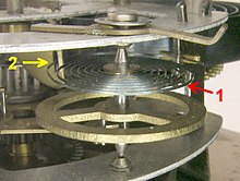
To accomplish this, the outer rim of the balance was made of a ‘sandwich’ of two metals; a layer of steel on the inside fused to a layer of brass on the outside. Strips of this bimetallic construction bend toward the steel side when they are warmed, because the thermal expansion of brass is greater than steel. The rim was cut open at two points next to the spokes of the wheel, so it resembled an S-shape (see figure) with two circular bimetallic ‘arms’. These wheels are sometimes referred to as "Z-balances". A temperature increase makes the arms bend inward toward the center of the wheel, and the shift of mass inward reduces the moment of inertia of the balance, similar to the way a spinning ice skater can reduce her moment of inertia by pulling in her arms. This reduction in the moment of inertia compensated for the reduced torque produced by the weaker balance spring. The amount of compensation is adjusted by moveable weights on the arms. Marine chronometers with this type of balance had errors of only 3–4 seconds per day over a wide temperature range. By the 1870s compensated balances began to be used in watches.
Middle temperature error

The standard Earnshaw compensation balance dramatically reduced error due to temperature variations, but it didn't eliminate it. As first described by J. G. Ulrich, a compensated balance adjusted to keep correct time at a given low and high temperature will be a few seconds per day fast at intermediate temperatures. The reason is that the moment of inertia of the balance varies as the square of the radius of the compensation arms, and thus of the temperature. But the elasticity of the spring varies linearly with temperature.
To mitigate this problem, chronometer makers adopted various 'auxiliary compensation' schemes, which reduced error below 1 second per day. Such schemes consisted for example of small bimetallic arms attached to the inside of the balance wheel. Such compensators could only bend in one direction toward the center of the balance wheel, but bending outward would be blocked by the wheel itself. The blocked movement causes a non-linear temperature response that could slightly better compensate the elasticity changes in the spring. Most of the chronometers that came in first in the annual Greenwich Observatory trials between 1850 and 1914 were auxiliary compensation designs. Auxiliary compensation was never used in watches because of its complexity.
Better materials

The bimetallic compensated balance wheel was made obsolete in the early 20th century by advances in metallurgy. Charles Édouard Guillaume won a Nobel prize for the 1896 invention of Invar, a nickel steel alloy with very low thermal expansion, and Elinvar (Elasticité invariable) an alloy whose elasticity is unchanged over a wide temperature range, for balance springs. A solid Invar balance with a spring of Elinvar was largely unaffected by temperature, so it replaced the difficult-to-adjust bimetallic balance. This led to a series of improved low temperature coefficient alloys for balances and springs.
Before developing Elinvar, Guillaume also invented an alloy to compensate for middle temperature error in bimetallic balances by endowing it with a negative quadratic temperature coefficient. This alloy, named anibal, is a slight variation of invar. It almost completely negated the temperature effect of the steel hairspring, but still required a bimetal compensated balance wheel, known as a Guillaume balance wheel. This design later fell out of use in favor of single metal Invar balances with Elinvar springs. The quadratic coefficient is defined by its place in the equation of expansion of a material;
- where;
- is the length of the sample at some reference temperature
- is the temperature above the reference
- is the length of the sample at temperature
- is the linear coefficient of expansion
- is the quadratic coefficient of expansion


Candle Timer
A candle is an ignitable wick embedded in wax, or another flammable solid substance such as tallow, that provides light, and in some cases, a fragrance. A candle can also provide heat, or be used as a method of keeping time.
A person who makes candles is traditionally known as a chandler.[1] Various devices have been invented to hold candles, from simple tabletop candlesticks, also known as candle holders, to elaborate chandeliers.[2]
For a candle to burn, a heat source (commonly a naked flame) is used to light the candle's wick, which melts and vaporizes a small amount of fuel (the wax). Once vaporized, the fuel combines with oxygen in the atmosphere to ignite and form a constant flame. This flame provides sufficient heat to keep the candle burning via a self-sustaining chain of events: the heat of the flame melts the top of the mass of solid fuel; the liquefied fuel then moves upward through the wick via capillary action; the liquefied fuel finally vaporizes to burn within the candle's flame.
As the solid fuel (wax) is melted and burned, the candle becomes shorter. Portions of the wick that are not emitting vaporized fuel are consumed in the flame. The incineration of the wick limits the exposed length of the wick, thus maintaining a constant burning temperature and rate of fuel consumption. Some wicks require regular trimming with scissors (or a specialized wick trimmer), usually to about one-quarter inch (~0.7 cm), to promote slower, steady burning, and also to prevent smoking. Special candle-scissors called "snuffers" were produced for this purpose in the 20th century and were often combined with an extinguisher. In modern candles, the wick is constructed so that it curves over as it burns. This ensures that the end of the wick gets oxygen and is then consumed by fire—a self-trimming wick

Prior to the candle, people used oil lamps in which a lit wick rested in a container of liquid oil. Liquid oil lamps had a tendency to spill, and the wick had to be advanced by hand. Romans began making true dipped candles from tallow, beginning around 500 BCE.[5] European candles of antiquity were made from various forms of natural fat, tallow, and wax. In Ancient Rome, candles were made of tallow due to the prohibitive cost of beeswax.[6] It is possible that they also existed in Ancient Greece, but imprecise terminology makes it difficult to determine.[6] The earliest surviving candles originated in Han China around 200 BC. These early Chinese candles were made from whale fat.
During the Middle Ages, tallow candles were most commonly used. By the 13th century, candle making had become a guild craft in England and France. The candle makers (chandlers) went from house to house making candles from the kitchen fats saved for that purpose, or made and sold their own candles from small candle shops.[7] Beeswax, compared to animal-based tallow, burned cleanly, without smoky flame. Beeswax candles were expensive, and relatively few people could afford to burn them in their homes in medieval Europe. However, they were widely used for church ceremonies.[8]
In the 18th and 19th centuries, spermaceti, a waxy substance produced by the sperm whale, was used to produce a superior candle that burned longer, brighter and gave off no offensive smell.[9] Later in the 18th century, colza oil and rapeseed oil came into use as much cheaper substitutes.
Modern era

The manufacture of candles became an industrialized mass market in the mid 19th century. In 1834, Joseph Morgan,[10] a pewterer from Manchester, England, patented a machine that revolutionised candle making. It allowed for continuous production of molded candles by using a cylinder with a moveable piston to eject candles as they solidified. This more efficient mechanized production produced about 1,500 candles per hour. This allowed candles to be an affordable commodity for the masses.[11] Candlemakers also began to fashion wicks out of tightly braided (rather than simply twisted) strands of cotton. This technique makes wicks curl over as they burn, maintaining the height of the wick and therefore the flame. Because much of the excess wick is incinerated, these are referred to as "self-trimming" or "self-consuming" wicks.[12]
In the mid-1850s, James Young succeeded in distilling paraffin wax from coal and oil shales at Bathgate in West Lothian and developed a commercially viable method of production.[13] Paraffin could be used to make inexpensive candles of high quality. It was a bluish-white wax, which burned cleanly and left no unpleasant odor, unlike tallow candles. By the end of the 19th century candles were made from paraffin wax and stearic acid.
By the late 19th century, Price's Candles, based in London, was the largest candle manufacturer in the world.[14] Founded by William Wilson in 1830,[15] the company pioneered the implementation of the technique of steam distillation, and was thus able to manufacture candles from a wide range of raw materials, including skin fat, bone fat, fish oil and industrial greases.
Despite advances in candle making, the candle industry declined rapidly upon the introduction of superior methods of lighting, including kerosene and lamps and the 1879 invention of the incandescent light bulb. From this point on, candles came to be marketed as more of a decorative item.
Use

.jpg)
Before the invention of electric lighting, candles and oil lamps were commonly used for illumination. In areas without electricity, they are still used routinely. Until the 20th century, candles were more common in northern Europe. In southern Europe and the Mediterranean, oil lamps predominated.
In the developed world today, candles are used mainly for their aesthetic value and scent, particularly to set a soft, warm, or romantic ambiance, for emergency lighting during electrical power failures, and for religious or ritual purposes.
Other uses
With the fairly consistent and measurable burning of a candle, a common use of candles was to tell the time. The candle designed for this purpose might have time measurements, usually in hours, marked along the wax. The Song dynasty in China (960–1279) used candle clocks.
By the 18th century, candle clocks were being made with weights set into the sides of the candle. As the candle melted, the weights fell off and made a noise as they fell into a bowl.
In the days leading to Christmas some people burn a candle a set amount to represent each day, as marked on the candle. The type of candle used in this way is called the Advent candle, although this term is also used to refer to a candle that decorates an Advent wreath.
Components
Wax

.jpg)
For most of recorded history candles were made from tallow (rendered from beef or mutton-fat) or beeswax. From the mid 1800s they were also made from spermaceti, a waxy substance derived from the Sperm whale, which in turn spurred demand for the substance. Candles were also made from stearin (initially manufactured from animal fats but now produced almost exclusively from palm waxes). Today, most candles are made from paraffin wax, a product of petroleum refining.
Candles can also be made from microcrystalline wax, beeswax (a byproduct of honey collection), gel (a mixture of polymer and mineral oil), or some plant waxes (generally palm, carnauba, bayberry, or soybean wax).
The size of the flame and corresponding rate of burning is controlled largely by the candle wick.
Production methods utilize extrusion moulding. More traditional production methods entail melting the solid fuel by the controlled application of heat. The liquid is then poured into a mould or a wick is repeatedly immersed in the liquid to create a dipped tapered candle. Often fragrance oils, essential oils or aniline-based dye is added.
Wick
A candle wick works by capillary action, drawing ("wicking") the melted wax or fuel up to the flame. When the liquid fuel reaches the flame, it vaporizes and combusts. The candle wick influences how the candle burns. Important characteristics of the wick include diameter, stiffness, fire-resistance, and tethering.
A candle wick is a piece of string or cord that holds the flame of a candle. Commercial wicks are made from braided cotton. The wick's capillarity determines the rate at which the melted hydrocarbon is conveyed to the flame. If the capillarity is too great, the molten wax streams down the side of the candle. Wicks are often infused with a variety of chemicals to modify their burning characteristics. For example, it is usually desirable that the wick not glow after the flame is extinguished. Typical agents are ammonium nitrate and ammonium sulfate.
Characteristics
Light

Based on measurements of a taper-type, paraffin wax candle, a modern candle typically burns at a steady rate of about 0.1 g/min, releasing heat at roughly 80 W.[22] The light produced is about 13 lumens, for a luminous efficacy of about 0.16 lumens per watt (luminous efficacy of a source) – almost a hundred times lower than an incandescent light bulb.
The luminous intensity of a typical candle is approximately one candela. The SI unit, candela, was in fact based on an older unit called the candlepower, which represented the luminous intensity emitted by a candle made to particular specifications (a "standard candle"). The modern unit is defined in a more precise and repeatable way, but was chosen such that a candle's luminous intensity is still about one candela.
Temperature
The hottest part of a candle flame is just above the very dull blue part to one side of the flame, at the base. At this point, the flame is about 1,400 °C. However note that this part of the flame is very small and releases little heat energy. The blue color is due to chemiluminescence, while the visible yellow color is due to radiative emission from hot soot particles. The soot is formed through a series of complex chemical reactions, leading from the fuel molecule through molecular growth, until multi-carbon ring compounds are formed. The thermal structure of a flame is complex, hundreds of degrees over very short distances leading to extremely steep temperature gradients. On average, the flame temperature is about 1,000 °C. The color temperature is approximately 1,000 K.
Candle flame

A candle flame is formed because wax vaporizes on burning. It has three distinct regions. The innermost zone, directly above the wick, contains wax that has been vaporized but that is unburnt. It is the darkest zone. The middle zone is yellow and luminous. As it is an oxygen depleted zone, insufficient oxygen exists to burn all of the wax vapor. As such, partial combustion of wax takes place. The zone also contains unburnt carbon vapor. The temperature in this region is hotter than the innermost zone, but cooler than the outer zone. The outer zone is the area where the flame is the hottest and complete combustion of wax takes place. It is light blue in color and not normally visible.
The main determinant of the height of a candle flame is the diameter of the wick. This is evidenced in tealights where the wick is very thin and the flame is very small. Candles whose main purpose is illumination use a much thicker wick.
History of study
One of Michael Faraday's significant works was The Chemical History of a Candle, where he gives an in-depth analysis of the evolutionary development, workings and science of candles.
Hazards
According to the U.S. National Fire Protection Association, candles are a leading source of residential fires in the United States with almost 10% of civilian injuries and 6% of fatalities from fire attributed to candles.[27] A candle flame that is longer than its laminar smoke point will emit soot.[28] Proper wick trimming will reduce soot emissions from most candles.
The liquid wax is hot and can cause skin burns, but the amount and temperature are generally rather limited and the burns are seldom serious. The best way to avoid getting burned from splashed wax is to use a candle snuffer instead of blowing on the flame. A candle snuffer is usually a small metal cup on the end of a long handle. Placing the snuffer over the flame cuts off the oxygen supply. Snuffers were common in the home when candles were the main source of lighting before electric lights were available. Ornate snuffers, often combined with a taper for lighting, are still found in those churches which regularly use large candles.
Glass candle-holders are sometimes cracked by thermal shock from the candle flame, particularly when the candle burns down to the end. When burning candles in glass holders or jars, users should avoid lighting candles with chipped or cracked containers, and stop use once 1/2 inch or less of wax remains.
A former worry regarding the safety of candles was that a lead core was used in the wicks to keep them upright in container candles. Without a stiff core, the wicks of a container candle could sag and drown in the deep wax pool. Concerns rose that the lead in these wicks would vaporize during the burning process, releasing lead vapors — a known health and developmental hazard. Lead core wicks have not been common since the 1970s. Today, most metal-cored wicks use zinc or a zinc alloy, which has become the industry standard. Wicks made from specially treated paper and cotton are also available.
Regulation
International markets have developed a range of standards and regulations to ensure compliance, while maintaining and improving safety, including:
- Europe: GPSD, EN 15493, EN 15494, EN 15426, EN 14059, REACH, RAL-GZ 041 Candles (Germany), French Decree 91-1175
- United States: ASTM F2058, ASTM F2179, ASTM F2417, ASTM F2601, ASTM F2326, California Proposition 65, CONEG
- China: QB/T 2119 Basic Candle, QB/T 2902 Art Candle, QB/T 2903 Jar Candle, GB/T 22256 Jelly Candle
Accessories
Candle holders
Decorative candleholders, especially those shaped as a pedestal, are called candlesticks; if multiple candle tapers are held, the term candelabrum is also used. The root form of chandelier is from the word for candle, but now usually refers to an electric fixture. The word chandelier is sometimes now used to describe a hanging fixture designed to hold multiple tapers.
Many candle holders use a friction-tight socket to keep the candle upright. In this case, a candle that is slightly too wide will not fit in the holder, and a candle that is slightly too narrow will wobble. Candles that are too big can be trimmed to fit with a knife; candles that are too small can be fitted with aluminium foil. Traditionally, the candle and candle holders were made in the same place, so they were appropriately sized, but international trade has combined the modern candle with existing holders, which makes the ill-fitting candle more common. This friction tight socket is only needed for the federals and the tapers. For tea light candles, there are a variety of candle holders, including small glass holders and elaborate multi-candle stands. The same is true for votives. Wall sconces are available for tea light and votive candles. For pillar-type candles, the assortment of candle holders is broad. A fireproof plate, such as a glass plate or small mirror, is a candle holder for a pillar-style candle. A pedestal of any kind, with the appropriate-sized fireproof top, is another option. A large glass bowl with a large flat bottom and tall mostly vertical curved sides is called a hurricane. The pillar-style candle is placed at the bottom center of the hurricane. A hurricane on a pedestal is sometimes sold as a unit.
A bobèche is a drip-catching ring, which may also be affixed to a candle holder, or used independently of one. Bobèches can range from ornate metal or glass, to simple plastic, cardboard, or wax paper. Use of paper or plastic bobèches is common at events where candles are distributed to a crowd or audience, such as Christmas carolers or people at other concerts/festivals.
Candle followers
These are glass or metal tubes with an internal stricture partway along, which sit around the top of a lit candle. As the candle burns, the wax melts and the follower holds the melted wax in, whilst the stricture rests on the topmost solid portion of wax. Candle followers are often deliberately heavy or weighted to ensure they move down as the candle burns lower, maintaining a seal and preventing wax escape. The purpose of a candle follower is threefold:
- To contain the melted wax, making the candle more efficient, avoiding mess, and producing a more even burn.
- As a decoration, either due to the ornate nature of the device, or (in the case of a glass follower) through light dispersion or colouration.
- If necessary, to shield the flame from wind.
Candle followers are often found in churches on altar candles.
Candle snuffers
Candle snuffers are instruments used to extinguish burning candles by smothering the flame with a small metal cup that is suspended from a long handle, and thus depriving it of oxygen. An older meaning refers to a scissor-like tool used to trim the wick of a candle. With skill, this could be done without extinguishing the flame. The instrument now known as a candle snuffer was formerly called an "extinguisher" or "douter".
Hourglass Timer
Antiquity

The origin of the hourglass is unclear. Its predecessor the clepsydra, or water clock, is known to have existed in Babylon and Egypt as early as the 16th century BCE. According to the Journal of the British Archaeological Association the so-called clepsammia were in use before the time of St. Jerome (335 CE), and the first potential representation of an hourglass is in a sarcophagus dated c. 350 CE,[1] representing the wedding of Peleus and Thetis, discovered in Rome in the 18th century, and studied by Winckelmann in the 19th century, who remarked the hourglass held by Morpheus in his hands.[2] However, it is disputed whether object in question is a clepsammia or a similarly-shaped clepsydra; no other hourglass clearly appears in the historical record for another thousand years.
Reappearance in the Early Middle Ages

There are no records of the hourglass existing in Europe prior to the Early Middle Ages, such as invention by the Ancient Greeks; the first supported evidences appears from the 8th century CE, crafted by a Frankish monk named Liutprand who served at the cathedral in Chartres, France. But it was not until the 14th century that the hourglass was seen commonly, the earliest firm evidence being a depiction in the 1338 fresco Allegory of Good Government by Ambrogio Lorenzetti.[6]
Use of the marine sandglass has been recorded since the 14th century. The written records about it were mostly from logbooks of European ships.[5] In the same period it appears in other records and lists of ships stores. The earliest recorded reference that can be said with certainty to refer to a marine sandglass dates from c. 1345, in a receipt of Thomas de Stetesham, clerk of the King's ship La George, in the reign of Edward III of England; translated from the Latin, the receipt says: in 1345:[7][8]
Marine sandglasses were very popular on board ships, as they were the most dependable measurement of time while at sea. Unlike the clepsydra, the motion of the ship while sailing did not affect the hourglass. The fact that the hourglass also used granular materials instead of liquids gave it more accurate measurements, as the clepsydra was prone to get condensation inside it during temperature changes.[9] Seamen found that the hourglass was able to help them determine longitude, distance east or west from a certain point, with reasonable accuracy.
The hourglass also found popularity on land. As the use of mechanical clocks to indicate the times of events like church services became more common, creating a "need to keep track of time", the demand for time-measuring devices increased. Hourglasses were essentially inexpensive, as they required no rare technology to make and their contents were not hard to come by, and as the manufacturing of these instruments became more common, their uses became more practical.[9]
Hourglasses were commonly seen in use in churches, homes, and work places to measure sermons, cooking time, and time spent on breaks from labor.[5] Because they were being used for more everyday tasks, the model of the hourglass began to shrink. The smaller models were more practical and very popular as they made timing more discreet.
After 1500, the hourglass was not as widespread as it had been. This was due to the development of the mechanical clock, which became more accurate, smaller and cheaper, and made keeping time easier. The hourglass, however, did not disappear entirely. Although they became relatively less useful as clock technology advanced, hourglasses remained desirable in their design. The oldest known surviving hourglass resides in the British Museum in London.
Not until the 18th century did John Harrison come up with a marine chronometer that significantly improved on the stability of the hourglass at sea. Taking elements from the design logic behind the hourglass, he made a marine chronometer in 1761 that was able to accurately measure the journey from England to Jamaica accurate within five seconds.

Design
Little written evidence exists to explain why its external form is the shape that it is. The glass bulbs used, however, have changed in style and design over time. While the main designs have always been ampoule in shape, the bulbs were not always connected. The first hourglasses were two separate bulbs with a cord wrapped at their union that was then coated in wax to hold the piece together and let sand flow in between.[10] It was not until 1760 that both bulbs were blown together to keep moisture out of the bulbs and regulate the pressure within the bulb that varied the flow.[9]
Material
While some early hourglasses actually did use sand as the granular mixture to measure time, many did not use sand at all. The material used in most bulbs was a combination of "powdered marble, tin/lead oxides, and pulverized, burnt eggshell". Over time, different textures of granule matter were tested to see which gave the most constant flow within the bulbs. It was later discovered that for the perfect flow to be achieved the ratio of granule bead to the width of the bulb neck needed to be 1/12 or more but not greater than 1/2 the neck of the bulb.
Practical uses

Hourglasses were an early dependable and accurate measure of time. The rate of flow of the sand is independent of the depth in the upper reservoir, and the instrument will not freeze in cold weather.[5] From the 15th century onwards, hourglasses were being used in a range of applications at sea, in the church, in industry, and in cookery.
During the voyage of Ferdinand Magellan around the globe, 18 hourglasses from Barcelona were in the ship's inventory, after the trip had been authorized by King Charles I of Spain.[12] It was the job of a ship's page to turn the hourglasses and thus provide the times for the ship's log. Noon was the reference time for navigation, which did not depend on the glass, as the sun would be at its zenith.[13] A number of sandglasses could be fixed in a common frame, each with a different operating time, e.g. as in a four-way Italian sandglass likely from the 17th century, in the collections of the Science Museum, in South Kensington, London, which could measure intervals of quarter, half, three-quarters, and one hour (and which were also used in churches, for priests and ministers to measure lengths of sermons).
Modern practical uses

While they are no longer widely used for keeping time, some institutions do maintain them. Both houses of the Australian Parliament use three hourglasses to time certain procedures, such as divisions.
The sandglass is still widely used as the kitchen egg timer; for cooking eggs, a three-minute timer is typical, hence the name "egg timer" for three-minute hourglasses. Egg timers are sold widely as souvenirs.Sand timers are also sometimes used in games such as Pictionary and Boggle to implement a time constraint on rounds of play.
Symbolic uses

Unlike most other methods of measuring time, the hourglass concretely represents the present as being between the past and the future, and this has made it an enduring symbol of time itself.
The hourglass, sometimes with the addition of metaphorical wings, is often depicted as a symbol that human existence is fleeting, and that the "sands of time" will run out for every human life.[17] It was used thus on pirate flags, to strike fear into the hearts of the pirates' victims. In England, hourglasses were sometimes placed in coffins,[18] and they have graced gravestones for centuries. The hourglass was also used in alchemy as a symbol for hour.
The former Metropolitan Borough of Greenwich in London used an hourglass on its coat of arms, symbolising Greenwich's role as the origin of GMT. The district's successor, the Royal Borough of Greenwich, uses two hourglasses on its coat of arms.
Modern symbolic uses

Recognition of the hourglass as a symbol of time has survived its obsolescence as a timekeeper. For example, the American television soap opera Days of Our Lives, since its first broadcast in 1965, has displayed an hourglass in its opening credits, with the narration, "Like sands through the hourglass, so are the days of our lives," spoken by Macdonald Carey.
Various computer graphical user interfaces may change the pointer to an hourglass during a period when the program is in the middle of a task, and may not accept user input. During that period other programs, for example in different windows, may work normally. When such an hourglass does not disappear, it suggests a program is in an infinite loop and needs to be terminated, or is waiting for some external event (such as the user inserting a CD). Unicode has an HOURGLASS symbol at
U+231B (⌛).Hourglass motif

Because of its symmetry, graphic signs resembling an hourglass are seen in the art of cultures which never encountered such objects. Vertical pairs of triangles joined at the apex are common in Native American art; both in North America,[19] where it can represent, for example, the body of the Thunderbird or (in more elongated form) an enemy scalp,[20][21] and in South America, where it is believed to represent a Chuncho jungle dweller.[22] In Zulu textiles they symbolise a married man, as opposed to a pair of triangles joined at the base, which symbolise a married woman.[23] Neolithic examples can be seen among Spanish cave paintings. Observers have even given the name "hourglass motif" to shapes which have more complex symmetry, such as a repeating circle and cross pattern from the Solomon Islands.[26] Both the members of Project Tic Toc,from television series the Time Tunnel and the Challengers of the Unknown use symbols of the hourglasse representing either time travel or time running out.
Staircase timer
A staircase timer is an electrical switch used to control lighting on a staircase, corridor or lobby. A single action turns on the lights and they remain on for long enough to ascend or descend the stairs. The lights then turn themselves off automatically.

Typical UK pneumatic delay pushbutton switch
Operation
In a single occupancy domestic dwelling it is usual to provide two-way switching. The lights may be turned on or off from either the top, bottom or intermediate floors of the staircase. They remain on until turned off manually.
In a multiple occupancy dwelling, the drawback is that the cost of shared lighting is usually paid by the landlord. Individual tenants turn lights on, but have little reason to turn them off. Particularly so in the days of incandescent lamps this could be an appreciable cost. For this reason shared dwellings favour timers for staircases instead. The lights are turned on by a push-button switch on any floor. They remain on automatically for an adequate time to climb the stairs, then turn themselves off.
To provide longer lighting times when required the button may be pressed repeatedly. For this reason any timer should be a retriggerable monostable, i.e. the off delay lasts from the time of the last button press. There may also be a switch, sometimes a key switch, that can turn the lights on indefinitely for tasks such as cleaning.
Pneumatic timers
The first staircase timers were pneumatic pushbuttons. A large push-button, distinctly larger than a normal electrical switch, is pressed manually. An internal mechanism provides the delay. The internal piston is depressed by the button and holds the electrical contacts closed. This piston is spring-loaded to return upwards but is prevented from returning quickly by a pneumatic dashpot. This dashpot provides the timing function.
Electronic timers
.jpg)
An electronic timer allow simple push-buttons to be used. One timer is installed controlling the lights and any number of push-buttons, without pneumatic timers and connected in parallel, are used to trigger it. With many push-buttons, the cost savings for equipment may be substantial.
Occupancy detectors

PIR sensors may be used to control lighting in such areas. They avoid the need to press a push-button but otherwise operate as for electronic timers. As PIR sensors are not perfectly reliable a timer is needed to avoid the lights flashing off and on as the occupier moves out of detector range. The timer interval is short though compared to a push-button timer; it times the interval between sightings of the occupier, not the time of occupancy.
Such sensors are also used for restrooms. Owing to the variability of occupancy time in a restroom, a simple fixed timer was unworkable. This ability to cope with variably occupancy times is also useful when stairwells, lift lobbies and corridors must grant disabled access as they no longer discriminate in favour of an assumed transit time for an able-bodied person.
Time switch
A time switch (also called a timer switch, or simply timer) is a timer that operates an electric switch controlled by the timing mechanism.
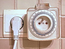
A simple 24-hour cyclical electromechanical time switch with a
The switch may be connected to an electric circuit operating from mains power, including via a relay or contactor; or low voltage, including battery-operated equipment in vehicles. It may be built into power circuits (as with a central heating or water heater timer), plugged into a wall outlet with equipment plugged into the timer instead of directly into the power point; or built into equipment as, for example, a sleep timer that turns off a television receiver after a set period.
The mechanism may be mechanical (e.g., clockwork; rarely used nowadays), electromechanical (e.g., a slowly rotating geared motor that mechanically operates switches) or electronic, with semiconductor timing circuitry and switching devices and no moving parts.
The timer may switch equipment on, off, or both, at a preset time or times, after a preset interval, or cyclically. A countdown time switch switches power, usually off, after a preset time. A cyclical timer switches equipment both on and off at preset times over a period, then repeats the cycle; the period is usually 24 hours or 7 days.
For example, a central heating timer may supply heat for a specified period during the morning and evening every weekday, and all day on weekends. A timer for an unattended slow cooker may switch on automatically at a time and for a period suitable to have food ready at mealtime. Likewise, a coffee maker may turn itself on early in the morning in time for awakening residents to have fresh coffee already brewed for them.
Timers may do other processing or have sensors; for example, a timer may switch on lights only during hours of darkness, using a seasonal algorithm[1] or light sensor. Combining the two allows a light to come on at sundown and go off at midnight, for example.
An astronomical (or astronomic) timer calculates dawn and dusk times for each day of the year based on the latitude and longitude (or just north/central/south and time zone on more cheaply made ones), and the day of the year (month and date), programmed by the user upon installation in addition to the usual time of day, except in the case of GPS enabled astronomic timers wherein all programming is fully automatic. This eliminates the need for a photocell (which may be repeatedly triggered on and off by the light which it operates) or for repeatedly re-setting a regular timer for seasonal changes in the length of day or for daylight-saving time. This allows exterior lighting like a porch light fixture to be controlled by simply replacing its indoor wall switch, or doing the same for a lamp in a dark interior corner (away from a window) by simply plugging-in a self-adjusting lamp timer.
Time switches can be used for many purposes, including saving electric energy by consuming it only when required, switching equipment on, off, or both at times required by some process, and home security (for example switching lights in a pattern that gives the impression that premises are attended) to reduce the likelihood of burglary or prowling.
Among applications are lighting (interior, exterior, and street lighting), cooking devices such as ovens, washing machines, and heating and cooling of buildings and vehicles.[2] Built-in automatic washing machine controllers are examples of very complex electromechanical and electronic timers cycles, starting and stopping many processes including pumps and valves to fill and empty the drum with water, heating, and rotating at different speeds, with different combinations of settings for different fabrics.


Time-to-digital converter
In electronic instrumentation and signal processing, a time to digital converter (abbreviated TDC) is a device for recognizing events and providing a digital representation of the time they occurred. For example, a TDC might output the time of arrival for each incoming pulse. Some applications wish to measure the time interval between two events rather than some notion of an absolute time.
In electronics time-to-digital converters (TDCs) or time digitizers are devices commonly used to measure a time interval and convert it into digital (binary) output. In some cases interpolating TDCs are also called time counters (TCs).
TDCs are used in many different applications, where the time interval between two signal pulses (start and stop pulse) should be determined. Measurement is started and stopped, when either the rising or the falling edge of a signal pulse crosses a set threshold. These requirements are fulfilled in many physical experiments, like time-of-flight and lifetime measurements in atomic and high energy physics, experiments that involve laser ranging and electronic research involving the testing of integrated circuits and high-speed data transfer .
Application
TDCs are used in applications where measurement events happen infrequently, such as high energy physics experiments, where the sheer number of data channels in most detectors ensures that each channel will be excited only infrequently by particles such as electrons, photons, and ions.
Coarse measurement

If the required time resolution is not high, then counters can be used to make the conversion.
Basic counter
In its simplest implementation, a TDC is simply a high-frequency counter that increments every clock cycle. The current contents of the counter represents the current time. When an event occurs, the counter's value is captured in an output register.
In that approach, the measurement is an integer number of clock cycles, so the measurement is quantized to a clock period. To get finer resolution, a faster clock is needed. The accuracy of the measurement depends upon the stability of the clock frequency.
Typically a TDC uses a crystal oscillator reference frequency for good long term stability. High stability crystal oscillators are usually relative low frequency such as 10 MHz (or 100 ns resolution). To get better resolution, a phase-locked loop frequency multiplier can be used to generate a faster clock. One might, for example, multiply the crystal reference oscillator by 100 to get a clock rate of 1 GHz (1 ns resolution).
Counter technology
High clock rates impose additional design constraints on the counter: if the clock period is short, it is difficult to update the count. Binary counters, for example, need a fast carry architecture because they essentially add one to the previous counter value. A solution is using a hybrid counter architecture. A Johnson counter, for example, is a fast non-binary counter. It can be used to count very quickly the low order count; a more conventional binary counter can be used to accumulate the high order count. The fast counter is sometime called a prescaler.
The speed of counters fabricated in CMOS-technology is limited by the capacitance between the gate and the channel and by the resistance of the channel and the signal traces. The product of both is the cut-off-frequency. Modern chip technology allows multiple metal layers and therefore coils with a large number of windings to be inserted into the chip. This allows designers to peak the device for a specific frequency, which may lie above the cut-off-frequency of the original transistor.
A peaked variant of the Johnson counter is the traveling-wave counter which also achieves sub-cycle resolution. Other methods to achieve sub-cycle resolution include analog-to-digital converters and vernier Johnson counters.
Measuring a time interval

In most situations, the user does not want to just capture an arbitrary time that an event occurs, but wants to measure a time interval, the time between a start event and a stop event.
That can be done by measuring an arbitrary time both the start and stop events and subtracting. The measurement can be off by two counts.
The subtraction can be avoided if the counter is held at zero until the start event, counts during the interval, and then stops counting after the stop event.
Coarse counters base on a reference clock with signals generated at a stable frequency .[1] When the start signal is detected the counter starts counting clock signals and terminates counting after the stop signal is detected. The time interval between start and stop is then


Statistical counter
Since start, stop and clock signal are asynchronous, there is a uniform probability distribution of the start and stop signal-times between two subsequent clock pulses. This detuning of the start and stop signal from the clock pulses is called quantization error.
For a series of measurements on the same constant and asynchronous time interval one measures two different numbers of counted clock pulses and (see picture). These occur with probabilities


Measuring a time interval using a coarse counter with the averaging method described above is relatively time consuming because of the many repetitions that are needed to determine the probabilities and . In comparison to the other methods described later on, a coarse counter has a very limited resolution (1ns in case of a 1 GHz reference clock), but satisfies with its theoretically unlimited measuring range.


Fine measurement
In contrast to the coarse counter in the previous section, fine measurement methods with much better accuracy but far smaller measuring range are presented here.[1] Analogue methods like time interval stretching or double conversion as well as digital methods like tapped delay lines and the Vernier method are under examination. Though the analogue methods still obtain better accuracies, digital time interval measurement is often preferred due to its flexibility in integrated circuit technology and its robustness against external perturbations like temperature changes.
The counter implementation's accuracy is limited by the clock frequency. If time is measured by whole counts, then the resolution is limited to the clock period. For example, a 10 MHz clock has a resolution of 100 ns. To get resolution finer than a clock period, there are time interpolation circuits.[3] These circuits measure the fraction of a clock period: that is, the time between a clock event and the event being measured. The interpolation circuits often require a significant amount of time to perform their function; consequently, the TDC needs a quiet interval before the next measurement.
Ramp interpolator
When counting is not feasible because the clock rate would be too high, analog methods can be used. Analog methods are often used to measure intervals that are between 10 and 200 ns.[4] These methods often use a capacitor that is charged during the interval being measured. Initially, the capacitor is discharged to zero volts. When the start event occurs, the capacitor is charged with a constant current I1; the constant current causes the voltage v on the capacitor to increase linearly with time. The rising voltage is called the fast ramp. When the stop event occurs, the charging current is stopped. The voltage on the capacitor v is directly proportional to the time interval T and can be measured with an analog-to-digital converter (ADC). The resolution of such a system is in the range of 1 to 10 ps.[9]
Although a separate ADC can be used, the ADC step is often integrated into the interpolator. A second constant current I2 is used to discharge the capacitor at a constant but much slower rate (the slow ramp). The slow ramp might be 1/1000 of the fast ramp. This discharge effectively "stretches" the time interval;[10] it will take 1000 times as long for the capacitor to discharge to zero volts. The stretched interval can be measured with a counter. The measurement is similar to a dual-slope analog converter.
The dual-slope conversion can take a long time: a thousand or so clock ticks in the scheme described above. That limits how often a measurement can be made (dead time). Resolution of 1 ps with a 100 MHz (10 ns) clock requires a stretch ratio of 10,000 and implies a conversion time of 150 μs.[10] To decrease the conversion time, the interpolator circuit can be used twice in a residual interpolator technique.[10] The fast ramp is used initially as above to determine the time. The slow ramp is only at 1/100. The slow ramp will cross zero at some time during the clock period. When the ramp crosses zero, the fast ramp is turned on again to measure the crossing time (tresidual). Consequently, the time can be determined to 1 part in 10,000.
Interpolators are often used with a stable system clock. The start event is asynchronous, but the stop event is a following clock.[6][8] For convenience, imagine that the fast ramp rises exactly 1 volt during a 100 ns clock period. Assume the start event occurs at 67.3 ns after a clock pulse; the fast ramp integrator is triggered and starts rising. The asynchronous start event is also routed through a synchronizer that takes at least two clock pulses. By the next clock pulse, the ramp has risen to .327 V. By the second clock pulse, the ramp has risen to 1.327 V and the synchronizer reports the start event has been seen. The fast ramp is stopped and the slow ramp starts. The synchronizer output can be used to capture system time from a counter. After 1327 clocks, the slow ramp returns to its starting point, and interpolator knows that the event occurred 132.7 ns before the synchronizer reported.
The interpolator is actually more involved because there are synchronizer issues and current switching is not instantaneous.[11] Also, the interpolator must calibrate the height of the ramp to a clock period.[12]
Vernier
Vernier interpolator
The vernier method is more involved.[13] The method involves a triggerable oscillator[14] and a coincidence circuit. At the event, the integer clock count is stored and the oscillator is started. The triggered oscillator has a slightly different frequency than the clock oscillator. For sake of argument, say the triggered oscillator has a period that is 1 ns faster than the clock. If the event happened 67 ns after the last clock, then the triggered oscillator transition will slide by −1 ns after each subsequent clock pulse. The triggered oscillator will be at 66 ns after the next clock, at 65 ns after the second clock, and so forth. A coincidence detector looks for when the triggered oscillator and the clock transition at the same time, and that indicates the fraction time that needs to be added.
The interpolator design is more involved. The triggerable clock must be calibrated to clock. It must also start quickly and cleanly.
Vernier method
The Vernier method is a digital version of the time stretching method. Two only slightly detuned oscillators (with frequencies and ) start their signals with the arrival of the start and the stop signal. As soon as the leading edges of the oscillator signals coincide the measurement ends and the number of periods of the oscillators ( and respectively) lead to the original time interval :


Since highly reliable oscillators with stable and accurate frequency are still quite a challenge one also realizes the vernier method via two tapped delay lines using two slightly different cell delay times . This setting is called differential delay line or vernier delay line.

In the example presented here the first delay line affiliated with the start signal contains cells of D-flip-flops with delay which are initially set to transparent. During the transition of the start signal through one of those cells, the signal is delayed by and the state of the flip-flop is sampled as transparent. The second delay line belonging to the stop signal is composed of a series of non-inverting buffers with delay . Propagating through its channel the stop signal latches the flip-flops of the start signal's delay line. As soon as the stop signal passes the start signal, the latter is stopped and all leftover flip-flops are sampled opaque. Analogous to the above case of the oscillators the wanted time interval is then


with n the number of cells marked as transparent.
Tapped delay line

In general a tapped delay line contains a number of cells with well defined delay times . Propagating through this line the start signal is delayed. The state of the line is sampled at the time of the arrival of the stop signal. This can be realized for example with a line of D-flip-flop cells with a delay time . The start signal propagates through this line of transparent flip-flops and is delayed by a certain number of them. The output of each flip-flop is sampled on the fly. The stop signal latches all flip-flops while propagating through its channel undelayed and the start signal cannot propagate further. Now the time interval between start and stop signal is proportional to the number of flip-flops that were sampled as transparent.
Hybrid measurement

Counters can measure long intervals but have limited resolution. Interpolators have high resolution but they cannot measure long intervals. A hybrid approach can achieve both long intervals and high resolution.[1] The long interval can be measured with a counter. The counter information is supplemented with two time interpolators: one interpolator measures the (short) interval between the start event and a following clock event, and the second interpolator measure the interval between the stop event and a following clock event. The basic idea has some complications: the start and stop events are asynchronous, and one or both might happen close to a clock pulse. The counter and interpolators must agree on matching the start and end clock events. To accomplish that goal, synchronizers are used.
The common hybrid approach is the Nutt method. In this example the fine measurement circuit measures the time between start and stop pulse and the respective second nearest clock pulse of the coarse counter (Tstart, Tstop), detected by the synchronizer (see figure). Thus the wanted time interval is

with n the number of counter clock pulses and T0 the period of the coarse counter.
Flash Back
Time measurement has played a crucial role in the understanding of nature from the earliest times. Starting with sun, sand or water driven clocks we are able to use clocks today, based on the most precise caesium resonators.
The first direct predecessor of a TDC was invented in the year 1942 by Bruno Rossi for the measurement of muon lifetimes. It was designed as a time-to-amplitude-converter, constantly charging a capacitor during the measured time interval. The corresponding voltage is directly proportional to the time interval under examination.
While the basic concepts (like Vernier methods (Pierre Vernier 1584-1638) and time stretching) of dividing time into measurable intervals are still up-to-date, the implementation changed a lot during the past 50 years. Starting with vacuum tubes and ferrite pot-core transformers those ideas are implemented in complementary metal-oxide-semiconductor (CMOS) design today.
Errors
Regarding even the fine measuring methods presented, there are still errors one may wish remove or at least to consider. Non-linearities of the time-to-digital conversion for example can be identified by taking a large number of measurements of a poissonian distributed source (statistical code density test). Small deviations from the uniform distribution reveal the non-linearities. Inconveniently the statistical code density method is quite sensitive to external temperature changes. Thus stabilizing delay or phase-locked loop (DLL or PLL) circuits are recommended.
In a similar way, offset errors (non-zero readouts at T = 0) can be removed.
For long time intervals, the error due to instabilities in the reference clock (jitter) plays a major role. Thus clocks of superior quality are needed for such TDCs.
Furthermore, external noise sources can be eliminated in postprocessing by robust estimation methods.
Configurations
TDCs are currently built as stand-alone measuring devices in physical experiments or as system components like PCI cards. They can be made up of either discrete or integrated circuits.
Circuit design changes with the purpose of the TDC, which can either be a very good solution for single-shot TDCs with long dead times or some trade-off between dead-time and resolution for multi-shot TDCs.
Delay generator

The time-to-digital converter measures the time between a start event and a stop event. There is also a digital-to-time converter or delay generator. The delay generator converts a number to a time delay. When the delay generator gets a start pulse at its input, then it outputs a stop pulse after the specified delay. The architectures for TDC and delay generators are similar. Both use counters for long, stable, delays. Both must consider the problem of clock quantization errors.
For example, the Tektronix 7D11 Digital Delay uses a counter architecture. A digital delay may be set from 100 ns to 1 s in 100 ns increments. An analog circuit provides an additional fine delay of 0 to 100 ns. A 5 MHz reference clock drives a phase-locked loop to produce a stable 500 MHz clock. It is this fast clock that is gated by the (fine-delayed) start event and determines the main quantization error. The fast clock is divided down to 10 MHz and fed to main counter. The instrument quantization error depends primarily on the 500 MHz clock (2 ns steps), but other errors also enter; the instrument is specified to have 2.2 ns of jitter. The recycle time is 575 ns.
Just as a TDC may use interpolation to get finer than one clock period resolution, a delay generator may use similar techniques. The Hewlett-Packard 5359A High Resolution Time Synthesizer provides delays of 0 to 160 ms, has an accuracy of 1 ns, and achieves a typical jitter of 100 ps.[22] The design uses a triggered phase-locked oscillator that runs at 200 MHz. Interpolation is done with a ramp, an 8-bit digital-to-analog converter, and a comparator. The resolution is about 45 ps.
When the start pulse is received, then counts down and outputs a stop pulse. For low jitter the synchronous counter has to feed a zero flag from the most significant bit down to the least significant bit and then combine it with the output from the Johnson counter.
A digital-to-analog converter (DAC) could be used to achieve sub-cycle resolution, but it is easier to either use vernier Johnson counters or traveling-wave Johnson counters.
The delay generator can be used for pulse width modulation, e.g. to drive a MOSFET to load a Pockels cell within 8 ns with a specific charge.
The output of a delay generator can gate a digital-to-analog converter and so pulses of a variable height can be generated. This allows matching to low levels needed by analog electronics, higher levels for ECL and even higher levels for TTL. If a series of DACs is gated in sequence, variable pulse shapes can be generated to account for any transfer function.
Water clock
Modern designs

Only a few modern water clocks exist today. In 1979, French scientist Bernard Gitton began creating his Time-Flow Clocks, which are a modern-day approach to the historical version. His unique glass tube designs can be found in over 30 locations throughout the world, including one at NEMO Science Museum in Amsterdam, Europa-Center's The Clock of Flowing Time in Berlin, Centre Commercial Milenis in Guadeloupe, the Giant Water Clock at The Children's Museum of Indianapolis in Indianapolis, Indiana, the Abbotsford International Airport (formerly at Sevenoaks Shopping Centre) in Abbotsford, British Columbia, and the Shopping Iguatemi in São Paulo and Porto Alegre, Brazil.
Gitton's design relies on gravity powering multiple siphons in the same principle as the Pythagorean cup; for example, after the water level in the minute or hour display tubes is reached, an overflow tube starts to act as a siphon and thus empties the display tube. Actual time keeping is done by a calibrated pendulum powered by a water stream piped from the clock's reservoir. The pendulum has a carefully constructed container attached to it; this measures the water that is then poured into the display system. This means that strictly speaking these are not water clocks. The water is used to power the pendulum and to show the time in the display system. There are other modern designs of water clocks, including the Royal Gorge water clock in Colorado, the Woodgrove Mall in Nanaimo, British Columbia, and the Hornsby Water Clock in Sydney, Australia.
Temperature, water viscosity, and clock accuracy
When viscosity can be neglected, the outflow rate of the water is governed by Torricelli's law, or more generally, by Bernoulli's principle. Viscosity will dominate the outflow rate if the water flows out through a nozzle that is sufficiently long and thin, as given by the Hagen–Poiseuille equation. Approximately, the flow rate is for such design inversely proportional to the viscosity, which depends on the temperature. Liquids generally become less viscous as the temperature increases. In the case of water, the viscosity varies by a factor of about seven between zero and 100 degrees Celsius. Thus, a water clock with such a nozzle would run about seven times faster at 100 °C than at 0 °C. Water is about 25 percent more viscous at 20 °C than at 30 °C, and a variation in temperature of one degree Celsius, in this "room temperature" range, produces a change of viscosity of about two percent. Therefore, a water clock with such a nozzle that keeps good time at some given temperature would gain or lose about half an hour per day if it were one degree Celsius warmer or cooler. To make it keep time within one minute per day would require its temperature to be controlled within 1⁄30°C (about 1⁄17° Fahrenheit). There is no evidence that this was done in antiquity, so ancient water clocks with sufficiently thin and long nozzles (unlike the modern pendulum-controlled one described above) cannot have been reliably accurate by modern standards. Note, however, that while modern timepieces may not be reset for long periods, water clocks were likely reset every day, when refilled, based on a sundial, so the cumulative error would not have been great.
XO___XO SWWS 5 Different Timer Circuits
1. Long Duration Timer
This timer circuit is designed to switch on a 12 V load in a solar-powered installation for a preset period at the press of a button. When the period has expired a latching relay disconnects both the load and the controller circuit from the 12 V supply. The length of the period can be configured by making suitable changes to the microcontroller’s source code.
Working
The IC4060 is a 14- stage binary ripple counter which generates the basic time delay pulses. Variable resistor R1 can be adjusted to get different time delays. The delay pulse is obtained at IC 4060. The counter output is set by a jumper. The output from the 4060 goes to a transistor switch arrangement. A jumper sets the option. – the relay can turn ON when power and counting start then turn OFF after the count period, or – it can do the opposite. The relay will turn ON after the end of the count period and stay on so long as power is supplied to the circuit. When the supply is ON then transistors T1 and T2 are activated, then supply voltage is slowly goes to low. The supply voltage start at 12V when supply is ON then slowly goes down. This is working of long duration timer.
2. Fridge Timer
Generally the power consumption by the domestic refrigerator is quite large during peak hours from 6 pm to 9 pm and is much more on low voltage lines. Hence it is most appropriate to switch off the fridge during these peak hours.
Here a circuit is demonstrated which automatically switches off the fridge during this peak period and switches it on after two and half hours, thus enabling the saving of energy.
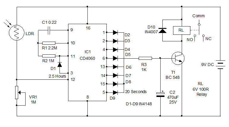 Circuit Working
An LDR is used as the light sensor to detect the darkness around 6 pm. During day light, LDR has less resistance and it conducts. This keeps the reset pin 12 of IC1 high and the IC remains off without oscillating. VR1 adjust the resetting of IC at the particular light level in the room, say around 6 pm. When the light level in the room drops below the preset level, IC1 starts oscillating. After 20 seconds, its pin 5 turns high and triggers the relay driver transistor T1. Normally the power supply to the fridge is provided through the Comm and NC contacts of the relay. So when the relay triggers, the contacts break and the power to the fridge will be cut off.
The other outputs of the IC1 turns high one by one as the binary counter advances. But since the outputs are taken to the base of T1 through the diodes D2 through D9, T1 remains on during the entire period until the output pin 3 turns high after 2.5 hours. When the output pin 3 turns high, diode D1 forward biases and inhibits the oscillation of IC. At this time, all the outputs except pin 3 turns low and T1 switches off. Relay deenergizes and the Fridge again gets power through the NC contact. This condition remains as such till the LDR gets light again in the morning.IC1 then resets and pin3 again turns low. So during day time also, the Fridge works as usual. Only during the peak hours say between 6 pm and 8.30 pm, the Fridge remains off. By increasing the value of either C1 or R1, you can increase the time delay to 3 or 4 hours.
How to Set?
Assemble the circuit on a common PCB and enclose in a Box. You can use the case of a stabilizer so that the output plug can be fixed easily. Use a 9 volt 500 mA transformer power supply for the circuit. Take the phase line from the Transformer primary and connect it to the Common contact of the relay. Connect another wire to the NC contact of the relay and connect its other end to the Live pin of the socket. Take a wire from the Neutral of the transformer primary and connect it to the Neutral pin of the Socket. So now the socket can be used to plug in the Fridge. Fix the LDR outside the box where day light is available (note that the room light during night should not fall on the LDR). If the room light is not sufficient during day time, keep the LDR outside the room and connect it to the circuit using thin wires. Adjust the preset VR1 to set the sensitivity of LDR at the particular light level.
3. Programmable Industrial Timer
Industries often require programmable timer for certain repetitive nature of load on and off. In this circuit design we used an AT80C52 microcontroller which is programmed to set the time by using set input switches. A LCD display helps in setting the time period while a relay duly interfaced from the microcontroller operates the load as per the entry time for on period and off period is made.
Circuit Description
On pressing the start button, the display interfaced to the Microcontroller starts showing the relevant instructions. The ON time of the load is then entered by the user. This is done by pressing the INC button. Pressing the button more than once increases the ON time. Pressing the DEC button decreases the ON time. This time is then stored in the microcontroller by pressing the enter button. Initially the transistor is connected to the 5V signal and starts conducting and as a result the relay is energized and the lamp is glowing. On pressing the relevant button, the time for which the lamp glows can be increased or decreased. This is done by the Microcontroller sending high logic pulses accordingly to the transistor based on the time stored. On pressing the emergency off button, the Microcontroller receives a interrupt signal and accordingly generates a low logic signal to the transistor to switch off the relay and in turn the load.
4. RF based Programmable Industrial Timer
This is an improved version of the programmable Industrial Timer where the time of switching of loads in controlled remotely using RF communication.
At the transmitter side, 4 push buttons are interfaced to the Encoder-the start button, the INC button, the DEC button and the Enter button. On pressing the relevant buttons, the Encoder accordingly generates a digital code for the input, i.e. converts the parallel data into serial form. This serial data is then transmitted using RF module.
At the receiver side, the Decoder converts the received serial data into parallel form, which is the original data. The Microcontroller pins are connected to the output of the Decoder and accordingly, based on the input received, the Microcontroller controls the conduction of the transistor, so as to control the switching of the relay and thus the load remains switched on for the time set at the transmitter side.
5. Auto Dimming Aquarium Light
We all are familiar with Aquariums which we often use at homes for decorative purpose for some one having a desire to keep fish at home (not for eating of course!).Here a basic system is demonstrated through it is possible to lighten up the aquarium during the day and night and switch it off or dim it around midnight.
Basic principle involves controlling the triggering of the relay using an oscillating IC.
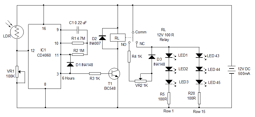 The circuit uses the Binary counter IC CD4060 to get the time delay of 6 hours after the sunset. An LDR is used as light sensor to control the working of IC. During day time, LDR offers less resistance and it conducts. This keeps the reset pin 12 of IC high and it remains off. When the intensity of day light decreases, the resistance of LDR increases and the IC starts oscillating. This happens around 6 pm (as set by VR1). The oscillating components of IC1 are C1 and R1 which gives a time delay of 6 hours to turns the output pin 3 to high state. When the output pin3 goes high (after 6 hours), transistor T1 turns on and the Relay triggers. At the same time, diode D1 forward biases and inhibits the oscillation of IC.IC then latches and keeps the relay energized till the resetting of the IC in the morning.
Normally the power supply to the LED panel is through the Common and NC (Normally Connected) contacts of the relay. But when the relay energize, the power supply to the LED panel will be bypassed through the NO (Normally Open) contact of the relay. Before entering the LED panel, power passes through R4 and VR2 so that the LEDs turn dim. VR2 is used to adjust the brightness of LEDs. The light from the LED panel can be adjusted from dim state to fully off state using VR2.
The LED panel consists of 45 LEDs of single color or two colors. The LEDs should be high bright transparent type to give sufficient brightness. Arrange the LEDs in 15 row each consisting of 3 LEDs in series with a 100 ohms current limiting resistor. Only two rows are shown in the diagram. Arrange all the 15 rows as shown in the diagram. It is better to fix the LEDs in a long sheet of common PCB and connect the panel to the relay using thin wires. The LDR should be placed in a position to get day light. Connect the LDR using thin plastic wires and place it near the window or outside so as to get day light.
IC4060
Let us now have a brief about IC 4060
IC CD 4060 is an excellent IC for designing timer for different applications. By selecting suitable values of the timing components, it is possible to adjust the timing from a few seconds to several hours. CD 4060 is the Oscillator cum Binary counter cum Frequency divider integrated circuit that has a built in oscillator based on three inverters. The basic frequency of the internal oscillator can be set using the external capacitor- resistor combination. IC CD4060 works between 5 and 15 volts DC while the CMOS version HEF 4060 works down to three volts.
Pin 16 of the IC is the Vcc pin. If a 100 uF capacitor is connected to this pin, the IC gets more stability even if the input voltage fluctuates slightly. Pin 8 is the ground pin.
Timing Circuit
IC CD4060 requires external timing components to feed oscillations to the Clock in pin 11. The timing capacitor is connected to pin 9 and the timing resistor to pin 10. Clock in pin is 11 which also require a high value resistor around 1M. Instead of the external timing components, clock pulses from an oscillator can be fed to clock in pin 11. With the external timing components, the IC will start oscillating and the time delay for the outputs depends on the values of the timing resistor and timing capacitor.
Resetting
Pin 12 of the IC is the reset pin. IC oscillates only if the reset pin is at ground potential. So a 0.1 capacitor and a 100K resistor are connected to reset the IC at power on. Then it will start oscillating.
Outputs and Binary Counting
The IC has 10 outputs each can source around 10 mA current and voltage slightly less than that of Vcc. The outputs are numbered as Q3 through Q13. Output Q10 is missing so that double time can be obtained from Q11. This enhances more flexibility to get more timing. Each output from Q3 to Q13 goes high after completing one timing cycle. Inside the IC there is an oscillator and 14 serially connected Bistables. This arrangement is called Ripple Cascade arrangement. Initially, the oscillation is applied to the first bistable which then drives the second bistable and so on. The signal input is divided by two in each bistable so a total 15 signals are available each of half the frequency of the previous one. Out of these 15 signals, 10 signals are available from Q3 to Q13. So the second output gets double time than that of first output. The Third output gets double time than that of the Second one. This continues and maximum time will be available at the last output Q13. But during that time, other outputs will also give high output based on their timing.
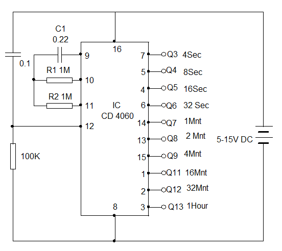 Latching the IC
CD 4060 based timer can be latched to block the oscillation and to keep the output high until resetting. For this IN4148 diode can be used. When the high output is connected to Pin11 through the diode, the clocking will be inhibited when that output becomes high. The IC will stars oscillation again only if it is reset by switching off the power.
Formulae for the Timing Cycle
Time t = 2 n / f osc = Seconds
n is the selected Q output number
2 n = Q output number = 2 x Q no times Eg. Q3 output = 2x2x2 = 8
f osc = 1 / 2.5 (R1XC1) = in Hertz
R1 is the resistance at pin 10 in Ohms and C1, the capacitor at pin 9 in Farads.
For example if R1 is 1M and C1 0.22 the basic frequency f osc is
1 / 2.5(1,000,000 x 0.000,000 22) = 1.8 Hz
If the selected output is Q3 then 2 n is 2 x 2 x 2 = 8
Therefore time period (in seconds) is t = 2 n / 1.8 Hz = 8 / 1.8 = 4.4 seconds
XO___XO SWWS 2002 The Mystery of Moon Dust
Lunar dust is fine, like a powder, but it cuts like glass. It’s formed when meteoroids crash on the moon’s surface, heating and pulverizing rocks and dirt, which contain silica and metals such as iron. Since there’s no wind or water to smooth rough edges, the tiny grains are sharp and jagged, and cling to nearly everything.
” The dust sullied spacesuits and ate away layers of moon boots. Over the course of six Apollo missions, not one rock box maintained its vacuum seal. Dust followed the astronauts back into their ships, too. According to Schmitt, it smelled like gunpowder and made breathing difficult. No one knows precisely what the microscopic particles do to human lungs.
The dust not only coats the moon’s surface, but floats up to sixty miles above it—as part of its exosphere, where particles are bound to the moon by gravity, but are so sparse that they rarely collide. In the nineteen-sixties, Surveyor probes filmed a glowing cloud floating just above the lunar surface during sunrise. Later, Apollo 17 astronaut Gene Cernan, while orbiting the moon, recorded a similar phenomenon at the sharp line where lunar day meets night, called the terminator. Cernan sketched a series of pictures illustrating the changing dustscape; streams of particles popped off the ground and levitated, and the resulting cloud came into sharper focus as the astronauts’ orbiter approached daylight. Since there’s no wind to form and sustain the clouds, their origin is something of a mystery. It’s presumed that they’re made of dust, but no one fully understands how or why they do their thing.
It’s possible that an electrical field forms at the terminator line—where sunlight meets shadow—that could knock dust particles aloft. Mihály Horányi, a physicist at the University of Colorado, in Boulder, has demonstrated that moon dust can indeed respond to such electric fields. But he suspects that the mechanism isn’t strong enough to create and sustain the mysterious, glowing clouds.
Data from a new mission should help scientists find a better explanation. While it’s been decades since American astronauts and rovers have explored the moon, lunar dust is of interest once again, with international and commercial space programs announcing a number of potential robotic and human moonshots. In September, nasa launched a small probe, the Lunar Atmosphere and Dust Environment Explorer, or ladee, to analyze, for the next few months, the dust and molecules that surround earth’s only natural satellite.
The probe is about the size of a small car, and is encased in solar panels. Atop its nose are three boxy instruments: a dust counter partly designed by Horányi, and two chemical detectors to identify molecules like helium and sodium. Jutting from its side is the Lunar Laser Communication Demonstration, which sends data, like the number of large and small particles and their locations, back to Earth with a laser beam; it recently broke a record for the fastest communication between nasa and the moon, transmitting data nearly two hundred and forty thousand miles at six hundred and twenty-two megabits per second, or roughly seventy-one times the speed of the average broadband connection in the United States.
The two-hundred-and-eighty-million-dollar mission is well-timed, because ladee’s detectors will get a relatively untainted picture of the dust density and chemical profile of the moon, ahead of expected traffic: China, India, Japan, and Russia have announced plans to launch moon probes and rovers in the coming years. Google’s Lunar X prize challenges engineers to build an unmanned craft with cameras to land on the moon and transmit “mooncasts” back to Earth by 2015. Golden Spike Company, another space startup, has ambitions for manned missions in the next decade or so.
Jupiter Facts
Jupiter is the fifth planet from the Sun and by far the largest. Jupiter is more than twice as massive as all the other planets combined (the mass of Jupiter is 318 times that of Earth). Jupiter is the fourth brightest object in the sky (after the Sun, the Moon and Venus). It has been known since prehistoric times as a bright "wandering star". But in 1610 when Galileo first pointed a telescope at the sky he discovered Jupiter's four large moons Io, Europa, Ganymede and Callisto (now known as the Galilean moons) and recorded their motions back and forth around Jupiter. This was the first discovery of a center of motion not apparently centered on the Earth. It was a major point in favor of Copernicus'sheliocentric theory of the motions of the planets (along with other new evidence from his telescope: the phases of Venus and the mountains on the Moon). Galileo's outspoken support of the Copernican theory got him in trouble with the Inquisition. Today anyone can repeat Galileo's observations (without fear of retribution :-) using binoculars or an inexpensive telescope.
Jupiter was first visited by Pioneer 10 in 1973 and later by Pioneer 11, Voyager 1, Voyager 2 and Ulysses. The spacecraft Galileo orbited Jupiter for eight years. It is still regularly observed by the Hubble Space Telescope.
 The gas planets do not have solid surfaces, their gaseous material simply gets denser with depth (the radii and diameters quoted for the planets are for levels corresponding to a pressure of 1 atmosphere). What we see when looking at these planets is the tops of clouds high in their atmospheres (slightly above the 1 atmosphere level).
Jupiter is about 90% hydrogen and 10% helium (by numbers of atoms, 75/25% by mass) with traces of methane, water, ammonia and "rock". This is very close to the composition of the primordial Solar Nebula from which the entire solar system was formed. Saturn has a similar composition, but Uranus and Neptune have much less hydrogen and helium.
Our knowledge of the interior of Jupiter (and the other gas planets) is highly indirect and likely to remain so for some time. (The data from Galileo's atmospheric probe goes down only about 150 km below the cloud tops.)
Jupiter probably has a core of rocky material amounting to something like 10 to 15 Earth-masses.
Above the core lies the main bulk of the planet in the form of liquid metallic hydrogen. This exotic form of the most common of elements is possible only at pressures exceeding 4 million bars, as is the case in the interior of Jupiter (and Saturn). Liquid metallic hydrogen consists of ionized protons and electrons (like the interior of the Sun but at a far lower temperature). At the temperature and pressure of Jupiter's interior hydrogen is a liquid, not a gas. It is an electrical conductor and the source of Jupiter's magnetic field. This layer probably also contains some helium and traces of various "ices".
The outermost layer is composed primarily of ordinary molecular hydrogen and helium which is liquid in the interior and gaseous further out. The atmosphere we see is just the very top of this deep layer. Water, carbon dioxide, methane and other simple molecules are also present in tiny amounts.
Recent experiments have shown that hydrogen does not change phase suddenly. Therefore the interiors of the jovian planets probably have indistinct boundaries between their various interior layers.
 Three distinct layers of clouds are believed to exist consisting of ammonia ice, ammonium hydrosulfide and a mixture of ice and water. However, the preliminary resultsfrom the Galileo probe show only faint indications of clouds (one instrument seems to have detected the topmost layer while another may have seen the second). But the probe's entry point (left) was unusual -- Earth-based telescopic observations and morerecent observations by the Galileo orbiter suggest that the probe entry site may well have been one of the warmest and least cloudy areas on Jupiter at that time.
Data from the Galileo atmospheric probe also indicate that there is much less water than expected. The expectation was that Jupiter's atmosphere would contain about twice the amount of oxygen (combined with the abundant hydrogen to make water) as the Sun. But it now appears that the actual concentration much less than the Sun's. Also surprising was the high temperature and density of the uppermost parts of the atmosphere.
 Jupiter and the other gas planets have high velocity winds which are confined in wide bands of latitude. The winds blow in opposite directions in adjacent bands. Slight chemical and temperature differences between these bands are responsible for the colored bands that dominate the planet's appearance. The light colored bands are called zones; the dark ones belts. The bands have been known for some time on Jupiter, but the complex vortices in the boundary regions between the bands were first seen by Voyager. The data from the Galileo probe indicate that the winds are even faster than expected (more than 400 mph) and extend down into as far as the probe was able to observe; they may extend down thousands of kilometers into the interior. Jupiter's atmosphere was also found to be quite turbulent. This indicates that Jupiter's winds are driven in large part by its internal heat rather than from solar input as on Earth.
The vivid colors seen in Jupiter's clouds are probably the result of subtle chemical reactions of the trace elements in Jupiter's atmosphere, perhaps involving sulfur whose compounds take on a wide variety of colors, but the details are unknown.
The colors correlate with the cloud's altitude: blue lowest, followed by browns and whites, with reds highest. Sometimes we see the lower layers through holes in the upper ones.
 The Great Red Spot (GRS) has been seen by Earthly observers for more than 300 years (its discovery is usually attributed to Cassini, or Robert Hooke in the 17th century). The GRS is an oval about 12,000 by 25,000 km, big enough to hold two Earths. Other smaller but similar spots have been known for decades. Infrared observations and the direction of its rotation indicate that the GRS is a high-pressure region whose cloud tops are significantly higher and colder than the surrounding regions. Similar structures have been seen on Saturn and Neptune. It is not known how such structures can persist for so long.
Jupiter radiates more energy into space than it receives from the Sun. The interior of Jupiter is hot: the core is probably about 20,000 K. The heat is generated by the Kelvin-Helmholtz mechanism, the slow gravitational compression of the planet. (Jupiter does NOT produce energy by nuclear fusion as in the Sun; it is much too small and hence its interior is too cool to ignite nuclear reactions.) This interior heat probably causes convection deep within Jupiter's liquid layers and is probably responsible for the complex motions we see in the cloud tops. Saturn and Neptune are similar to Jupiter in this respect, but oddly, Uranus is not.
Jupiter is just about as large in diameter as a gas planet can be. If more material were to be added, it would be compressed by gravity such that the overall radius would increase only slightly. A star can be larger only because of its internal (nuclear) heat source. (But Jupiter would have to be at least 80 times more massive to become a star.)
Jupiter has a huge magnetic field, much stronger than Earth's. Its magnetosphere extends more than 650 million km (past the orbit of Saturn!). (Note that Jupiter's magnetosphere is far from spherical -- it extends "only" a few million kilometers in the direction toward the Sun.) Jupiter's moons therefore lie within its magnetosphere, a fact which may partially explain some of the activity on Io. Unfortunately for future space travelers and of real concern to the designers of the Voyager and Galileo spacecraft, the environment near Jupiter contains high levels of energetic particles trapped by Jupiter's magnetic field. This "radiation" is similar to, but much more intense than, that found within Earth's Van Allen belts. It would be immediately fatal to an unprotected human being.
The Galileo atmospheric probe discovered a new intense radiation belt between Jupiter's ring and the uppermost atmospheric layers. This new belt is approximately 10 times as strong as Earth's Van Allen radiation belts. Surprisingly, this new belt was also found to contain high energy helium ions of unknown origin.
The Galileo atmospheric probe discovered a new intense radiation belt between Jupiter's ring and the uppermost atmospheric layers. This new belt is approximately 10 times as strong as Earth's Van Allen radiation belts. Surprisingly, this new belt was also found to contain high energy helium ions of unknown origin.
 Jupiter has rings like Saturn's, but much fainter and smaller (right). They were totally unexpected and were only discovered when two of the Voyager 1 scientists insisted that after traveling 1 billion km it was at least worth a quick look to see if any rings might be present. Everyone else thought that the chance of finding anything was nil, but there they were. It was a major coup. They have since been imaged in the infra-red from ground-based observatories and by Galileo.
Unlike Saturn's, Jupiter's rings are dark (albedo about .05). They're probably composed of very small grains of rocky material. Unlike Saturn's rings, they seem to contain no ice.
Particles in Jupiter's rings probably don't stay there for long (due to atmospheric and magnetic drag). The Galileo spacecraft found clear evidence that the rings are continuously resupplied by dust formed by micrometeor impacts on the four inner moons, which are very energetic because of Jupiter's large gravitational field. The inner halo ring is broadened by interactions with Jupiter's magnetic field.
 In July 1994, Comet Shoemaker-Levy 9 collided with Jupiter with spectacular results (left). The effects were clearly visible even with amateur telescopes. The debris from the collision was visible for nearly a year afterward with HST.
When it is in the nighttime sky, Jupiter is often the brightest "star" in the sky (it is second only to Venus, which is seldom visible in a dark sky). The four Galilean moons are easily visible with binoculars; a few bands and the Great Red Spot can be seen with a small astronomical telescope. There are several Web sites that show the current position of Jupiter (and the other planets) in the sky. More detailed and customized charts can be created with a planetarium program.
Jupiter's Satellites
 Jupiter has 67 known satellites : the four large Galilean moons plus many more small ones some of which have not yet been named:
- Jupiter is very gradually slowing down due to the tidal drag produced by the Galilean satellites. Also, the same tidal forces are changing the orbits of the moons, very slowly forcing them farther from Jupiter.
- Io, Europa and Ganymede are locked together in a 1:2:4 orbital resonance and their orbits evolve together. Callisto is almost part of this as well. In a few hundred million years, Callisto will be locked in too, orbiting at exactly twice the period of Ganymede (eight times the period of Io).
- Jupiter's satellites are named for other figures in the life of Zeus (mostly his numerous lovers).
- Many more small moons have been discovered recently but have not as yet been officially confirmed or named. The most up to date info on them can be found at Scott Sheppard's site.
           Distance  Radius    Mass
Satellite  (000 km)   (km)     (kg)   Discoverer   Date
---------  --------  ------  -------  ----------  -----
Metis           128      20  9.56e16  Synnott      1979
Adrastea        129      10  1.91e16  Jewitt       1979
Amalthea        181      98  7.17e18  Barnard      1892
Thebe           222      50  7.77e17  Synnott      1979
Io              422    1815  8.94e22  Galileo      1610
Europa          671    1569  4.80e22  Galileo      1610
Ganymede       1070    2631  1.48e23  Galileo      1610
Callisto       1883    2400  1.08e23  Galileo      1610
Leda          11094       8  5.68e15  Kowal        1974
Himalia       11480      93  9.56e18  Perrine      1904
Lysithea      11720      18  7.77e16  Nicholson    1938
Elara         11737      38  7.77e17  Perrine      1905
Ananke        21200      15  3.82e16  Nicholson    1951
Carme         22600      20  9.56e16  Nicholson    1938
Pasiphae      23500      25  1.91e17  Melotte      1908
Sinope        23700      18  7.77e16  Nicholson    1914
Values for the smaller moons are approximate. Many more small moons are not listed here.Jupiter's Rings
          Distance   Width   Mass
Ring      (km)        (km)   (kg)
----      --------   -----  ------
Halo      100000     22800   ?
Main      122800      6400  1e13
Gossamer  129200    214200   ?

It is Jupiter's mass that increases the amount of gravity.
Sun's gravity field is weaker at Jupiter's distance from the Sun compared to the Sun's gravitational field at Earth's distance from the Sun.
May be, Newton has proposed wrong idea of gravitational force.
None of the bodies experience any gravitational "forces." Jupiter and earth travel in nice inertial straight lines through curved space, and it's the warped space that makes the straight lines into a circle around the sun.
As per understanding and Einstein general relativity, GR can show that the earth is not orbiting the sun, rather the earth is travelling a straight path and space/time is wrapped/curved around the sun.
So gravity = space-time curvature.
Most meteorites derive from small bodies located in the main asteroid belt between Mars and Jupiter. Originally these bodies probably formed at a much wider range of heliocentric distances, as suggested by the distinct chemical and isotopic compositions of meteorites and by dynamical models indicating that the gravitational influence of the gas giants led to scattering of small bodies into the asteroid belt.

Honeywell Econoswitch 7-Day Solar Time Programmable Switch – $31.49
BalasHapus