
X . I
Force Measurement and Control as an option
last stability
Force sensing
As noted earlier touch sensors operate at the point of contact. If however it is required to measure the global forces and torques being exerted on an object by a robotic system, a multi-axis force measurement system will be required. If an object fixed in space is considered and subjected to a combination of the six possible orthogonal forces and torque, the object will deform. This can be measured by suitable sensors. In general a multi-axis force sensor incorporates a number of transducers measuring the load applied to a mechanical structure. These sensors greatly enhance the capabilities of a robotic system, by incorporating compliant damping control, active stiffness control and hybrid force control.For a generalized multi-axis force sensor, it is possible to write:
where [S] is a single-column matrix of the sensor outputs, [F] the applied forces, and [C] the n*6 coupling matrix, n being the number of sensors. Therefore,
where [D] = [C]-1 and is known as the decoupling matrix. Thus each of the six force can be calculated from:
To measure the forces and torques that the robot is subjecting an object to, it is necessary to design a suitable structure to mount within the robot's wrist. Atypical four beam structure, with eight strain gauges.
Even though the use of strain gauges is the most common method of measurement, there is no reason why other sensing techniques cannot be used. In addition structure could be constructed from magneto elastic material or use can be made of photo elastic or capacitive sensors. This decoupling matrix will only be valid if the cross-coupling between the eight gauges are negligible. In practice, cross-coupling will occur and the use of the above [D] matrix will result in errors of approximately 5%. To achieve negligible errors, the [D] matrix will need to contain 48 non-zero elements. The value of the elements can only be determined by calibration, using published methods.
There are a number of possible locations within a robo system where information regarding the applied force or torque can be measured, but in general the closer the sensor is located to the point of interest, the more accurate the measurement. Possible sensor locations are:
- At the interface between the end effector and the robo , as part of the robo �s wrist The location requires little re-engineering but the sensor must have high stiffness, to ensure that the disturbing forces are damped, allowing a high sampling rate. The high stiffness will minimize the deflections of the wrist under the applied forces that lead to positional errors. The sensor is positioned needs to be small so as not to restrict the movements of the robot within the workspace.
- Within the individual joints of the robo's by using joint torque sensing, however inertia, gravity loading and joint friction present in a manipulator will complicate the determination of the forces.
External to the Robot
It is possible to use any of the touch and tactile sensors external to the robo , the only limitation being the accuracy and resolution of the task being performed. While the Maltese cross sensor is usually placed within the robo's wrist, however, it can be placed are almost any point in the robot's structure. After the wrist, the most common place is integral to the robo's base, where it is termed a pedestal sensor. However, it is of only limited use at this point due to the complexity of the transformations.
Force control
- Passive correction:
- Active correction:
The Remote Centre Compliance or RCC system is a passive system, and relies on a spring and link structure.
The system can correct for minor error in position, both rotational and translational . However the design relies on the work piece ( object ) and the object withstanding the applied forces.
The Instrumented RCC is effectively the same structure, with the springs being replace by elastomer, and fitted with sensors. The resultant movement is used to determine the tips motion, and hence force.
Typical Applications
- Detecting contact
- Contour following
· The peg into hole problem.
This is a classic robo problem, consider the following:
The function of the chamfer is to improve the chances of the pen entering the hole. In general to achieve insertion, the part must rotate and translate during mating to correct for lateral and angular errors. If required detailed analysis can be undertaken of the problem.
The robo ( Ringing on Boat ) is only required to ally a constant motion, however the detection of jamming or wedging is required.
Jamming is defined as:
Wedging is defined as:
For information, it can be shown that for a successful insertion the following conditions need to be satisfied:
· The initial error in lateral position must be less than the width of the chamfer.
· At the start of the two point contact, the error in orientation must be less than (R - r)/mR to avoid wedging.
· The combination of forces in the x and z direction, and the required rotation torque must lie within a set of limits defined by the geometry of the application.
Force Control
Consider a robot cleaning a window, where due to manufacturing and environmental conditions the position of the window is not accurately know. Using a robot two modes of control are possible:
Position control:
Force control:
In force control, the robot must explicitly control the applied force to the object being manipulated. It should be noted that task constraints require control of the position is some of the cartesian degrees of freedom, and force in the others.
To undertake force control, a number of constraints need to be applied. A constraint is either:
Natural constraint
Artificial constraint
All constrains are referenced to a constraint frame attached to the task or manipulator, consider the driving of a screw into the work piece.
The constraint frame is at the tip of the screwdriver, and rotates with the task. It can be shown that the constraints are as follows:
Natural
Artificial
In order to control a task such a force controller is required, this can be achieved by a number of approaches, including the hybrid position-force control.
It should be noted that:
· Position control
· Force control
The block diagram of the controller is :
The diagonal constraint matrix, S, is defined as:
Hence the actuator control signal for the ith joint is given by:
One problem is the control relies on the kinematics to sort out the transforms, from cartesian ( coordinat x,y,z , etc ) to joints, hence the possibility for conflict is large.

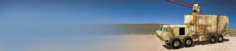
examples of control missile :
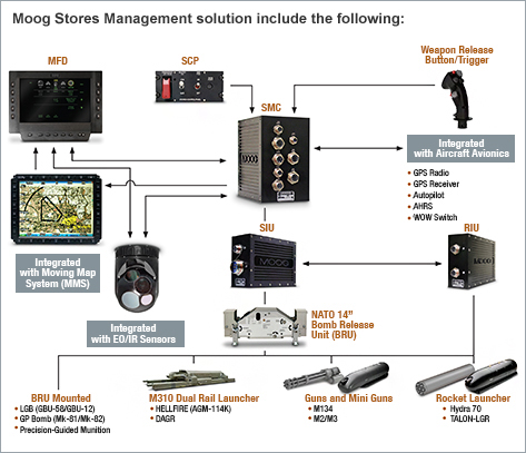

Figure : Force Sensors
Amplifiers and Controllers

image above is provides complete measurement solutions consisting of force sensor, strain gauge amplifiers and PID Controller in particular for drives in winding applications. The new 8-channel multi functional strain gauge amplifier module DCX was developed in close cooperation with our customers and results in particularly cost-effective solutions. Amplifiers interfaces are available in the common field bus standards: Profibus, Profinet, DeviceNet, EtherNet, EtherCAT, etc., both for field mounting as well as for DIN rail mounting, ATEX versions for hazardous areas are also available.

Wireless Tension Monitoring for Wires & Cables
X . II
Energy Robo ( Ringing on Boat )

A
robo is something that can be programmed and reprogrammed, by having a
manipulator mechanic / driver that is designed to move goods,
components or special tools with a variety of flexible programs / easily
customized to perform a variety of tasks. From where the robo makes energy? Robo power from:
1. The energy of the atomAtomic reactions are part of the natural chemical elements after
experiencing radioactivity, resulting in a source of energy for the
robo .
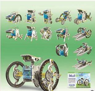
2. Energy from the sunSolar cells emit heat and convert it into electrical energy. Well, the electrical energy from the sun into energy for the robo .
3. The energy from the battery (Lithium)Lithium batteries will generate power source required the robo to move.
4. Energy from fossil fuelsConventional robo's first form of the steam engine. So the robots of this type using the fuel as energy.
5. Energy of glucoseModern robo experts have developed a natural energy source for bio robo form of glucose in muscle mechanics.
8 Main Components In Robo :
Robo as a function of the application raises the question !! What makes the robo able to think? What makes the robo can move? What makes the robo can get the information from the surrounding environment? What are the eyes, ears, skin for robo's ?
1. Controller. This is the main part of the robot, such as the brain in humans. This section serves to run the program, receive and process any information from the sensor input, and also send and control the output to the actuator, indicator, or even audio. The program is also downloaded to the controller. Popular development today is the microcontroller.

Figure sample microcontroller
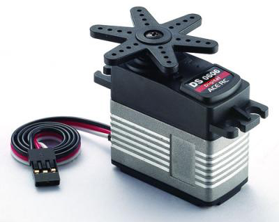
2. Actuator. This section is like a muscle in humans. Its function is to move the robo. For wheeled robo's usually use a DC motor, a wheel-turning, and make the robo move. And for a robo that walks on legs, Servo Motor is the right choice. Motor Servo is a DC motor which can be set spins. For this type of linear Hydraulic and pneumatic are also used to drive the robo.
3.Sensor. If humans have a sense of the robo has sensors. There are many types of sensors robo's, humans only have 5 senses, robo's can have a sensor with an unlimited number. Because the robo electronic creature, and rapidly evolving technology.


4. Battery. A source of energy for the robot. As your brain that needs nourishment, and the body you are in need carbohidrat or vitamins. Electricity is the lifeblood for the robot, and the robot can get the electricity needs for controllers, sensors, actuators and electronic components, of the battery.


5. Cable. If earlier battery such as blood, then this cable as vein blood flow path in each component of the robo , as well as the nerves that become the data for input and output.


6. Frame. As the bone supporting the servo robo . Also that form into various robo' s, and robo' s supporting performances. For such a wheeled robot line follower quite a box-shaped frame, or circular course, as a buffer DC Motor and a place to put the controller.

7. Chassis. The main framework of the robo , usually become the agency for the robo . Normally a robo mounted chassis on a wide variety of frames, with greater amounts.


8. Support. Is supporting the establishment of robot components, such as bolts and nuts.

X . III
MECHANICS AND ELECTRONICS AND ROBO ' S
Mechatronics and robo ' s
Mechatronics is a branch discipline engineer that combines mechanical engineering, electrical engineering, and software engineering. In this case, the machine operates automatically through the use of electric motors, servo-mechanisms, and other electrical devices with the use of special software. Examples of mechatronic systems are the most common CD-ROM drive. Mechanical systems open and close the drive, play CDs and shift the position of the laser, an optical system reads the data on the CD and convert it to bits. Integrated software control of the process, and linking content from a CD to a computer.
Robo 's is the application of science to create a robo mechatronics, which typically has been frequently used to perform dangerous tasks, unpleasant, or too repetitious tasks. This robot can be made in various shapes and sizes, everything is programmed in advance. An engineer would normally wear the science of kinematics and mechanics of creating a robo .
Robo' s are also used widely in industrial engineering. The use of robo' s will save employee salaries, to perform tasks that are difficult / dangerous, and also to ensure the quality remains. Many companies, especially in the automotive industry, has been using the robo , so sometimes it was so sophisticated, the robot can carry out the production process itself fully (no need humans anymore). For use outside the factory, robo' s are used in bomb disposal, space exploration, and many other fields.

Training FMS with learning robot SCORBOT-ER 4u, workbench CNC Mill and CNC Lathe
In modern robo's, actuators are often associated with mechanics. In mechanics, learned things about various styles that occur as a result of the arrangement of construction, the location of the center of gravity, and material properties. Taking into account the properties of mechanics, the robot will move with a stable and reduce the risk of falling.
Sensors on the robo is often related to the science of modern electronics. In the science of electronics studied matters related to electronic components, analog circuits, digital circuits, and micro controller. A sensor may be composed of a series of analog or digital circuits. Along with the increase in computer and electronics technology, the increased development will be sensors that can be fabricated with the mini size.
Intelligence systems on modern robo developed in a software. Artificial intelligence can be designed using an algorithm that allows the robo to move automatically, taking into account the information about which is read from the existing sensor. In addition there is a connectivity layer between intelligence system with sensors and actuators. Thus, data can be transferred between components managed by hardware using software created for the robo .
keywords that no one can explain the notion of robo's are:
* Access to information on the environment (via sensor)
* Can be programmed,
* It can carry out several different tasks
* Works automatically
* Smart (intelligent)
* Used in industry
* As a close friend in implementing macro perception
in the form of a vision, mission, strategies and tactics within the universe.
classification Robo :
1. Non Mobile Robo
This robot can not change position from one place to another, so that the robo can only move some parts of his body with specific functions that have been designed.
example: robot manipulator sleeved

2. Mobile Robo
Mobile can be interpreted move, so that the robo can move itself from one place to another. in terms of benefits, the robo is expected to assist humans in performing automation in transportation, moving platforms for industrial robo ' s, unmanned exploration and much more.
example: Robo Line Follower

3 . Combined Mobile Robot and Non Mobile Robot
This robot is an amalgamation of functions on mobile robots and non-mobile. so that they complement each other where non mobile robot functions can be helped by moving from one place to another.
4 . Humanoid robo
The robo is designed to mimic the anatomy and human behavior. The functions of the human body both arms, legs, eyes, and head movement joints and other parts of this on robo applied wherever possible.
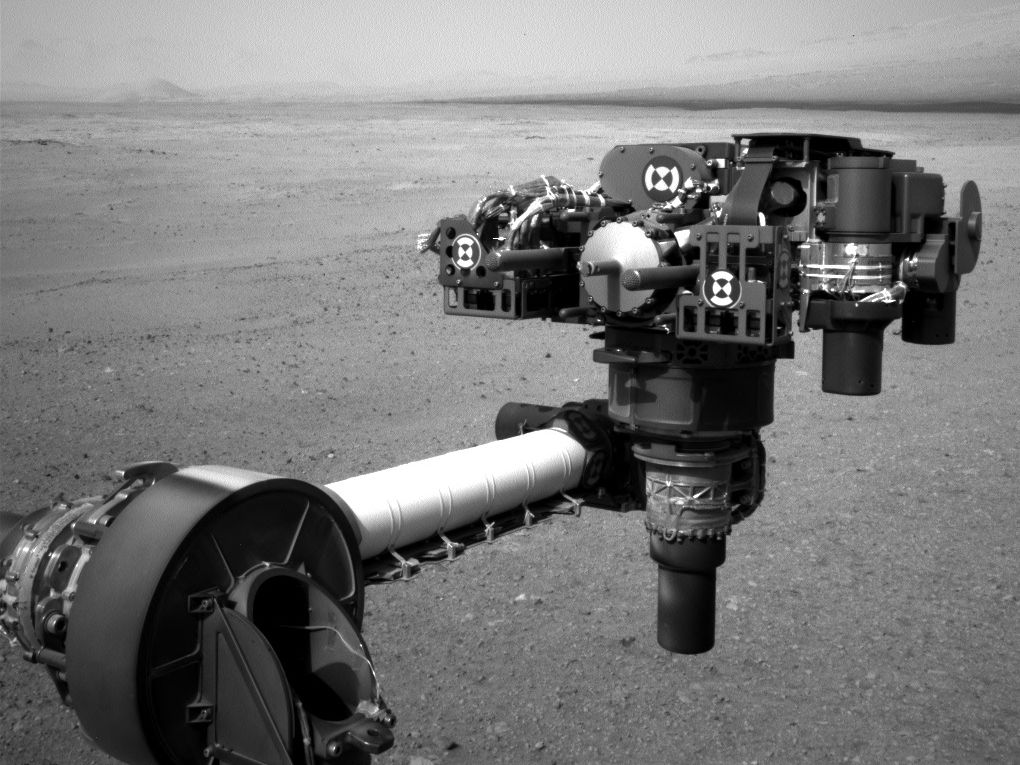
example: NASA Robo and robot ASIMO


Tidak ada komentar:
Posting Komentar