X . I
thrust force acting on the body of aircraft engines
Spoiler for Style Aerodynamics


Aircraft heavier than air was first flown by the Wright Brothers (Orville Wright and Wilbur Wright) using its own aircraft design called the Flyer, which was launched in 1903 in the United States. In addition to the Wright brothers, inventors listed several other aircraft that invented the airplane, among others, Samuel F Cody who commit crimes in the field Fan borough, England in 1910. After Wright era, aircraft undergone many modifications both in design, shape and aircraft engines to meet the needs air transport.
The basic principle of how aircraft to air the same for all aircraft, aircraft both dragonflies and super jumbo aircraft such as the Airbus A380.
That affects transform plane is flying style - the aerodynamic force that hits namely, lift (elevator), a drag (drag), gravity (gravity), and the thrust (trust).
The driving force obtained from the next plane propeller spinning at the end of the air (see picture). While the friction drag is an aircraft with the wind. Because the aircraft has a mass, then the force of gravity will bring the plane down, for which the necessary lifting force. Lift is produced from an aircraft wing.
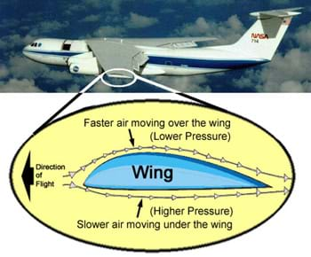
Aircraft wing is a key player to lift the fuselage. Wing cross-section is usually called "aerofoil" During the flight the air flow up and down the wing. The air to flow over the wing faster than the air flowing under the wing, so the air pressure above the lower air.
At the same time air under the wings have been turned down, resulting in a lifting force (air is pushed down is pushing the wing upwards - style action and reaction).


The driving force of the wing and the lower air pressure above the wing is what is needed for the aircraft in the air.
There are several factors that cause the aircraft to fly, including:
- Wings
Spoiler for Wings:


- Airfoil
A plane requires a lift or elevator is needed to fly. Lift is generated by the surface of a wing (wing) shaped airfoil.
Spoiler for Form airfoil cross-section at an airplane wing
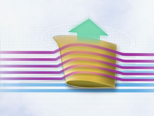

Lift is created because of the airflow passing over the top and the bottom around the airfoil. When flying, the air passing over the top of the airfoil will have a speed greater than the speed of air flow through the bottom of the airfoil. Then, on the lower surface of the airfoil will have a greater pressure than the surface above. The difference in pressure on the top and bottom that causes the lift or elevator on the wing. Hence the pressure to move from a large pressure area leading to a small pressure area, the pressure on the bottom of the airfoil will move towards the top of the airfoil so as to create the lift force on the wing. Lifting force that makes the aircraft can fly and float freely in the air.
Spoiler for Style Lift:

To move forward (both on land and in the air), the aircraft requires a thrust generated by the propulsion or commonly called by the engine (engine). Will thrust generated by the engine is commonly called the thrust.
There are several types of aircraft engine, including:
-Piston Engine
-Turbojet Engine
-Turboprop Engine
-Turbofan Engine
-Turbo shaft Engine
- Piston Engine
Piston engine or commonly called the piston engine, a machine that uses a piston (reciprocating) as the driving force. Piston that moves up and down in connecting with the crankshaft via the connecting rod to rotate the propeller or propellers. The piston can move up and down due to the combustion of the fuel-air mixture (fuel) in the combustion chamber (combustion chamber). Combustion in the combustion chamber to produce a hot gas expansion to drive the piston moves up and down.
Spoiler for Piston Engine:

Aircraft that use piston engines generally use a propeller as the driving force to generate thrust. Cross-sectional shape of the propeller itself as the wings, which is also shaped airfoil. Hence, in the propeller rotates it will generate thrust or thrust so that the aircraft can move forward. Aircraft with piston engine is a type of light aircraft or commonly called the light aircraft. This aircraft has a cruising range that is small and the flying height is not too high.
Basically, the working principle of all aircraft engines alike. Which is to harness the energy of combustion of the air fuel mixture which produces gas expansion which occurs in the combustion chamber cc (combustion chamber).
- Turbojet Engine
Named turbojet engine because it uses a turbine engine in generating power, and that means bursts jet / jet. Namely bursts cc combustion products inside out towards the turbine and turns the turbine, compressor and turbine rotate and move the other engine components.
Spoiler for Turboprop Engine:

The working principle of Turboprop engine together with the working process of the turbojet engine. What distinguishes it is contained in the engine's propeller. Propeller is connected to the turbine and compressor through the shaft.
Spoiler for Turboprop Engine How it Works:
- turbofan
Same with turboprop, turbofan same working principle with turbojet engine. The difference is in turbofan engines are a fan in front of the compressor. Fan function to suck air into the compressor.
Spoiler for Turbofan:
- Turboshaft engine
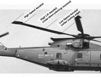
The working principle of the turboshaft engine is almost as expected in early turbojet engine. Engine is in use on the helicopter. In turboshaft engine, there is a shaft connected to the turbine. The shaft connects to the main rotor or blades on the helicopter. The rotor on the helicopter has an airfoil-shaped cross section.
The working principle of the turboshaft engine is almost as expected in early turbojet engine. Engine is in use on the helicopter. In turboshaft engine, there is a shaft connected to the turbine. The shaft connects to the main rotor or blades on the helicopter. The rotor on the helicopter has an airfoil-shaped cross section.
Spoiler for Turboshaft Engine:

- Field control (Flight Control Surface)
To move the aircraft (turn, swooping and rolling or turning), a pilot requires a control surface or control surface.
Primary control surface
Primary control surface or area of the main control is the best control surface to regulate the movement of aircraft while flying in the air.Aileron, elevator and rudder is the primary control surface on the aircraft.
1). Aileron is located on the wings, best used at the time of rolling (turning) in the air and the movement is at best a longitudinal axis, aileron is controlled using a control stick which is located in the cockpit.
2). Elevator located at the tail (empenage) or the horizontal stabilizer, used aircraft to piching (nod) and lateral movement on the axis of the aircraft, elevators controlled by using a control stick that was in the room the cockpit.
3). Rudder is located in the tail section precisely at the vertical stabilizer, in use the aircraft to perform yawing (turning) movement in the air and on the vertical axis of the aircraft, the rudder controlled by using rudder pedals located in the cockpit area.
Spoiler for spoiler for field control of the aircraft to the axis and direction of movement:

Spoiler for spoiler for field control of the aircraft to the axis and direction of movement:

Spoiler for spoiler for field control of the aircraft to the axis and direction of movement:


The porous titanium LFC glove is clearly
seen on the left wing of test aircraft No. 2, the two-seat F-16XL. A
suction system beneath the wing's surface was used to achieve laminar
flow over 46 percent of the glove's surface while flying at a speed of
Mach 2 in a successful demonstration of laminar flow at supersonic
speeds. (NASA Photo EC96-43548-7) .
X . II
Why The aircraft can fly?
The aircraft can fly because there is momentum of encouragement horizontal plane engine (Engine), then boost the engine will cause different air velocity below and above the wing. Air velocity above the wing will be greater than under the wings in because mileage layer of air flowing over the wing is greater than the mileage under his wing, the travel time through the layer of air over the wing and under the wings are the same. According to the law Bernoully , airspeed great cause small air pressure. so that the air pressure below the wing becomes larger than the top of the aircraft wing. So there will be lift (elevator), which makes the plane could fly.
There are four basic styles that work on the aircraft, namely:
1. Style obstacles
2. Style boost
3. Lift
4. Gravity (gravity)
In the first of Newton's laws can be concluded that the object tends to remain stationary or moving at a constant speed unless there was an effect (styles) from the outside who worked for him. This tendency occurs due to the balance of forces acting on the object. If you pull on an object as large as the encouragement, then things will not change in terms of horizontal movement. Likewise happens if gravity on objects as large as the style adopted, then to the vertical direction objects are also unchanged. This means that, if the balance is disturbed will result in changes to objects, can be horizontal or vertical.
According to Newton, the law stated that both objects with a certain mass which influenced the style of the thing will be accelerated. The implication of this law is for the case of aircraft, we can make it off the ground by providing lift for the aircraft, the lifting force must be greater than the force caused by the gravitational pull. The explanation of this lift will be clearer if we use Bernoulli's principle and Newton's third law.
As
has been stated by Bernoulli, the speed difference is then led to the
air pressure on the bottom of the wing will be greater than the pressure
on the top of an airplane wing. The pressure difference is what produces lift on the aircraft.
Please review the Bernoulli law:Ø The air flow rate at the upper side of the plane (v2) is greater compared to the air flow rate on the lower side air (v1). So according to the Bernoulli principle, the air pressure on the bottom side of the plane (p1) was greater than the air pressure on the upper side of the plane (p2).Ø Terms so that air can be lifted, the lifting force air (Fa) must be greater than gravity (W = mg), Fa> mg. When it reaches a certain height, to maintain the aircraft's altitude, it must be organized so: Fa = mg.Ø If you want to stir horizontal plane with a certain speed, then: the thrust must be greater than the drag (fd> fg), and lift force must be equal to gravity, (Fa = mg).Ø If the plane wanted to go up / increase the level fixed, then force must be equal to the force dorng Abat (fd = fg), and lift force must be greater than gravity (Fa = mg).
The application of physics in the lift of aircraft wingsLifting force on an airplane wing using the Bernoulli equation.Cross section of an airplane wing has a sharper rear and side parts of more curved than the bottom. This shape causes the airflow at the top is greater than at the bottom (v2> v1).Of the Bernoulli equation we get:

FIGURE bernoully principle
P1 + ½ r.v12 + r g h1 = P2 + ½ + r g h2 r.v22Altitude both wings can be considered equal (h1 = h2), so r g r g h1 = h2.And the above equation can be written:
P1 + P2 + ½ r.v12 = ½ r.v22
P1 - P2 = r.v22 ½ - ½ r.v12
P1 - P2 = ½ r (v22 - v12)
From the equation above it can be seen that v2> v1 we get P1> P2 to wing section area F1 = P1. A and F2 = P2. A and we get that F1> F2. Different styles on the bottom and top (F1 - F2) produces lift on the aircraft. Thus, the lifting force plane is defined as:
F1 - F2 = ½ r A (v22 - v12)
R = density of air (kg / m3)
Conclusion
There are four basic styles that work on the aircraft, namely:
1. Style obstacles
2. Style boost
3. Lift
4. Gravity (gravity)
An aircraft could fly or not depending on the weight of the aircraft, aircraft speed, and the size of the wings. The greater the air velocity, the greater the air velocity, and this means greater air lift. Similarly, the greater the size of the wing, the greater the force it up.
So that the aircraft can be lifted, the lifting force must be greater than the weight of the aircraft (F1 - F2> mg). if it has been at a certain altitude and the pilot wants to maintain its altitude (suspended in air), the air velocity should be arranged so that the lift force equal to gravity plane (F1 - F2 = mg).
X . III
the working principle of the foundation bernoully
In fluid dynamics, Bernoulli's principle states that an increase in the speed of a fluid occurs simultaneously with a decrease in pressure or a decrease in the fluid's potential energy. The principle is named after Daniel Bernoulli who published it in his book Hydrodynamica in 1738.
Bernoulli's principle can be applied to various types of fluid flow, resulting in various forms of Bernoulli's equation; there are different forms of Bernoulli's equation for different types of flow. The simple form of Bernoulli's equation is valid for incompressible flows (e.g. most liquid flows and gases moving at low Mach number). More advanced forms may be applied to compressible flows at higher Mach numbers (see the derivations of the Bernoulli equation).
Bernoulli's principle can be derived from the principle of conservation of energy. This states that, in a steady flow, the sum of all forms of energy in a fluid along a streamline is the same at all points on that streamline. This requires that the sum of kinetic energy, potential energy and internal energy remains constant. Thus an increase in the speed of the fluid – implying an increase in both its dynamic pressure and kinetic energy – occurs with a simultaneous decrease in (the sum of) its static pressure, potential energy and internal energy. If the fluid is flowing out of a reservoir, the sum of all forms of energy is the same on all streamlines because in a reservoir the energy per unit volume (the sum of pressure and gravitational potential ρ g h) is the same everywhere.
Bernoulli's principle can also be derived directly from Newton's 2nd law. If a small volume of fluid is flowing horizontally from a region of high pressure to a region of low pressure, then there is more pressure behind than in front. This gives a net force on the volume, accelerating it along the streamline.
Fluid particles are subject only to pressure and their own weight. If a fluid is flowing horizontally and along a section of a streamline, where the speed increases it can only be because the fluid on that section has moved from a region of higher pressure to a region of lower pressure; and if its speed decreases, it can only be because it has moved from a region of lower pressure to a region of higher pressure. Consequently, within a fluid flowing horizontally, the highest speed occurs where the pressure is lowest, and the lowest speed occurs where the pressure is highest.
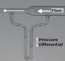
A flow of water into a venturi meter. The kinetic energy increases at the expense of the fluid pressure, as shown by the difference in height of the two columns of water.
Incompressible flow equation
In most flows of liquids, and of gases at low Mach number, the density of a fluid parcel can be considered to be constant, regardless of pressure variations in the flow. Therefore, the fluid can be considered to be incompressible and these flows are called incompressible flows. Bernoulli performed his experiments on liquids, so his equation in its original form is valid only for incompressible flow. A common form of Bernoulli's equation, valid at any arbitrary point along a streamline, is:-
(A)

is the fluid flow speed at a point on a streamline,
is the acceleration due to gravity,
is the elevation of the point above a reference plane, with the positive z-direction pointing upward – so in the direction opposite to the gravitational acceleration,
is the pressure at the chosen point, and
is the density of the fluid at all points in the fluid.
, and depend on the particular point on that streamline.The following assumptions must be met for this Bernoulli equation to apply:
- the flow must be steady, i.e. the fluid velocity at a point cannot change with time,
- the flow must be incompressible – even though pressure varies, the density must remain constant along a streamline;
- friction by viscous forces has to be negligible.

By multiplying with the fluid density
 , equation (A) can be rewritten as:

is dynamic pressure,
is the piezometric head or hydraulic head (the sum of the elevation z and the pressure head) and
is the total pressure (the sum of the static pressure p and dynamic pressure q).

Simplified form
In many applications of Bernoulli's equation, the change in the ρ g z term along the streamline is so small compared with the other terms that it can be ignored. For example, in the case of aircraft in flight, the change in height z along a streamline is so small the ρ g z term can be omitted. This allows the above equation to be presented in the following simplified form:
The simplified form of Bernoulli's equation can be summarized in the following memorable word equation:
- static pressure + dynamic pressure = total pressure
If the fluid flow is irrotational, the total pressure on every streamline is the same and Bernoulli's principle can be summarized as total pressure is constant everywhere in the fluid flow. It is reasonable to assume that irrotational flow exists in any situation where a large body of fluid is flowing past a solid body. Examples are aircraft in flight, and ships moving in open bodies of water. However, it is important to remember that Bernoulli's principle does not apply in the boundary layer or in fluid flow through long pipes.
If the fluid flow at some point along a stream line is brought to rest, this point is called a stagnation point, and at this point the total pressure is equal to the stagnation pressure.
Applicability of incompressible flow equation to flow of gases
Bernoulli's equation is sometimes valid for the flow of gases: provided that there is no transfer of kinetic or potential energy from the gas flow to the compression or expansion of the gas. If both the gas pressure and volume change simultaneously, then work will be done on or by the gas. In this case, Bernoulli's equation – in its incompressible flow form – cannot be assumed to be valid. However, if the gas process is entirely isobaric, or isochoric, then no work is done on or by the gas, (so the simple energy balance is not upset). According to the gas law, an isobaric or isochoric process is ordinarily the only way to ensure constant density in a gas. Also the gas density will be proportional to the ratio of pressure and absolute temperature, however this ratio will vary upon compression or expansion, no matter what non-zero quantity of heat is added or removed. The only exception is if the net heat transfer is zero, as in a complete thermodynamic cycle, or in an individual isentropic (frictionless adiabatic) process, and even then this reversible process must be reversed, to restore the gas to the original pressure and specific volume, and thus density. Only then is the original, unmodified Bernoulli equation applicable. In this case the equation can be used if the flow speed of the gas is sufficiently below the speed of sound, such that the variation in density of the gas (due to this effect) along each streamline can be ignored. Adiabatic flow at less than Mach 0.3 is generally considered to be slow enough.Unsteady potential flow
The Bernoulli equation for unsteady potential flow is used in the theory of ocean surface waves and acoustics.For an irrotational flow, the flow velocity can be described as the gradient ∇φ of a velocity potential φ. In that case, and for a constant density ρ, the momentum equations of the Euler equations can be integrated to:

Further f(t) can be made equal to zero by incorporating it into the velocity potential using the transformation
resulting in

The Bernoulli equation for unsteady potential flow also appears to play a central role in Luke's variational principle, a variational description of free-surface flows using the Lagrangian (not to be confused with Lagrangian coordinates).
Compressible flow equation
Bernoulli developed his principle from his observations on liquids, and his equation is applicable only to incompressible fluids, and compressible fluids up to approximately Mach number 0.3.It is possible to use the fundamental principles of physics to develop similar equations applicable to compressible fluids. There are numerous equations, each tailored for a particular application, but all are analogous to Bernoulli's equation and all rely on nothing more than the fundamental principles of physics such as Newton's laws of motion or the first law of thermodynamics.Compressible flow in fluid dynamics
For a compressible fluid, with a barotropic equation of state, and under the action of conservative forces,(constant along a streamline)
- p is the pressure
- ρ is the density
- v is the flow speed
- Ψ is the potential associated with the conservative force field, often the gravitational potential
(constant along a streamline)
- γ is the ratio of the specific heats of the fluid
- g is the acceleration due to gravity
- z is the elevation of the point above a reference plane

- p0 is the total pressure
- ρ0 is the total density
Compressible flow in thermodynamics
The most general form of the equation, suitable for use in thermodynamics in case of (quasi) steady flow, is:
Note that
 where ε is the thermodynamic energy per unit mass, also known as the specific internal energy. So, for constant internal energy ε the equation reduces to the incompressible-flow form.
The constant on the right hand side is often called the Bernoulli constant and denoted b. For steady inviscid adiabatic flow with no additional sources or sinks of energy, b is constant along any given streamline. More generally, when b may vary along streamlines, it still proves a useful parameter, related to the "head" of the fluid (see below).
When the change in Ψ can be ignored, a very useful form of this equation is:

When shock waves are present, in a reference frame in which the shock is stationary and the flow is steady, many of the parameters in the Bernoulli equation suffer abrupt changes in passing through the shock. The Bernoulli parameter itself, however, remains unaffected. An exception to this rule is radiative shocks, which violate the assumptions leading to the Bernoulli equation, namely the lack of additional sinks or sources of energy.
Applications

Condensation visible over the upper surface of an Airbus A340 wing caused by the fall in temperature accompanying the fall in pressure.
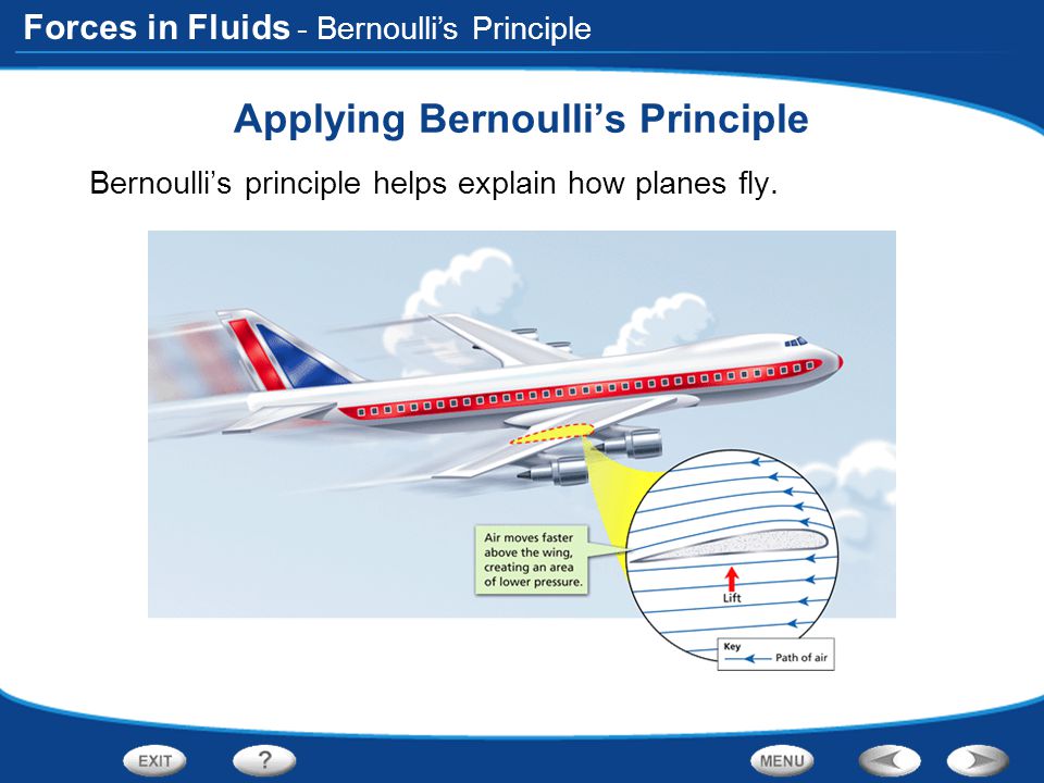
- Bernoulli's principle can be used to calculate the lift force on an airfoil, if the behaviour of the fluid flow in the vicinity of the foil is known. For example, if the air flowing past the top surface of an aircraft wing is moving faster than the air flowing past the bottom surface, then Bernoulli's principle implies that the pressure on the surfaces of the wing will be lower above than below. This pressure difference results in an upwards lifting force. Whenever the distribution of speed past the top and bottom surfaces of a wing is known, the lift forces can be calculated (to a good approximation) using Bernoulli's equations – established by Bernoulli over a century before the first man-made wings were used for the purpose of flight. Bernoulli's principle does not explain why the air flows faster past the top of the wing and slower past the underside. See the article on aerodynamic lift for more info.
- The carburettor used in many reciprocating engines contains a venturi to create a region of low pressure to draw fuel into the carburettor and mix it thoroughly with the incoming air. The low pressure in the throat of a venturi can be explained by Bernoulli's principle; in the narrow throat, the air is moving at its fastest speed and therefore it is at its lowest pressure.
- An injector on a steam locomotive (or static boiler).
- The pitot tube and static port on an aircraft are used to determine the airspeed of the aircraft. These two devices are connected to the airspeed indicator, which determines the dynamic pressure of the airflow past the aircraft. Dynamic pressure is the difference between stagnation pressure and static pressure. Bernoulli's principle is used to calibrate the airspeed indicator so that it displays the indicated airspeed appropriate to the dynamic pressure.
- The flow speed of a fluid can be measured using a device such as a Venturi meter or an orifice plate, which can be placed into a pipeline to reduce the diameter of the flow. For a horizontal device, the continuity equation shows that for an incompressible fluid, the reduction in diameter will cause an increase in the fluid flow speed. Subsequently Bernoulli's principle then shows that there must be a decrease in the pressure in the reduced diameter region. This phenomenon is known as the Venturi effect.
- The maximum possible drain rate for a tank with a hole or tap at the base can be calculated directly from Bernoulli's equation, and is found to be proportional to the square root of the height of the fluid in the tank. This is Torricelli's law, showing that Torricelli's law is compatible with Bernoulli's principle. Viscosity lowers this drain rate. This is reflected in the discharge coefficient, which is a function of the Reynolds number and the shape of the orifice.
- The Bernoulli grip relies on this principle to create a non-contact adhesive force between a surface and the gripper.

Misunderstandings about the generation of lift
Main article: Lift (force)
Many explanations for the generation of lift (on airfoils, propeller blades, etc.) can be found; some of these explanations can be misleading, and some are false,in particular the idea that air particles flowing above and below a
cambered wing should reach simultaneously the trailing edge. This has
been a source of heated discussion over the years. In particular, there
has been debate about whether lift is best explained by Bernoulli's
principle or Newton's laws of motion.
Modern writings agree that both Bernoulli's principle and Newton's laws
are relevant and either can be used to correctly describe lift.Several of these explanations use the Bernoulli principle to connect the flow kinematics to the flow-induced pressures. In cases of incorrect (or partially correct) explanations relying on the Bernoulli principle, the errors generally occur in the assumptions on the flow kinematics and how these are produced. It is not the Bernoulli principle itself that is questioned because this principle is well established (the airflow above the wing is faster, the question is why it is faster).
Misapplications of Bernoulli's principle in common classroom demonstrations
There are several common classroom demonstrations that are sometimes incorrectly explained using Bernoulli's principle. One involves holding a piece of paper horizontally so that it droops downward and then blowing over the top of it. As the demonstrator blows over the paper, the paper rises. It is then asserted that this is because "faster moving air has lower pressure".One problem with this explanation can be seen by blowing along the bottom of the paper: were the deflection due simply to faster moving air one would expect the paper to deflect downward, but the paper deflects upward regardless of whether the faster moving air is on the top or the bottom. Another problem is that when the air leaves the demonstrator's mouth it has the same pressure as the surrounding air; the air does not have lower pressure just because it is moving; in the demonstration, the static pressure of the air leaving the demonstrator's mouth is equal to the pressure of the surrounding air. A third problem is that it is false to make a connection between the flow on the two sides of the paper using Bernoulli’s equation since the air above and below are different flow fields and Bernoulli's principle only applies within a flow field.
As the wording of the principle can change its implications, stating the principle correctly is important.What Bernoulli's principle actually says is that within a flow of constant energy, when fluid flows through a region of lower pressure it speeds up and vice versa.Thus, Bernoulli's principle concerns itself with changes in speed and changes in pressure within a flow field. It cannot be used to compare different flow fields.
A correct explanation of why the paper rises would observe that the plume follows the curve of the paper and that a curved streamline will develop a pressure gradient perpendicular to the direction of flow, with the lower pressure on the inside of the curve.Bernoulli's principle predicts that the decrease in pressure is associated with an increase in speed, i.e. that as the air passes over the paper it speeds up and moves faster than it was moving when it left the demonstrator's mouth. But this is not apparent from the demonstration.
Other common classroom demonstrations, such as blowing between two suspended spheres, inflating a large bag, or suspending a ball in an airstream are sometimes explained in a similarly misleading manner by saying "faster moving air has lower pressure".

X . IIII
Working Principles and Methods Push Power Jet Engine
The airplane is one of the objects is always interesting to observe. This time we will see the development of vital organs one aircraft that is the engine driving the Jet engine manifold or in the world of so-called flying Aircraft Power Plant.

Why is it called a vital organ of course. Jet engine is like the human heart organ which controls the pulse
rate, blood pressure, which generally ultimately determines human
survival itself.
If the human heart stops, then all the activities of life supported by it will also cease. Likewise with aircraft engines. If the engine dies for any reason, then generally the internal system on board the aircraft will be threatened its survival. This is because the machine provides the function of internal systems that exist within the airplane. What are these systems?
Such systems are Electrical Systems (Electrical System), Hydraulic systems (Hydraulic System), the system pressure cabins (Pressurization System), Control Systems Aircraft (Flight Control System), as well as other secondary systems of existing aircraft.
Landing gear is very dependent on the presence of this Hydraulic System. Passenger in aircraft depends on the existence of a cabin pressure system, in order to breathe freely and above normal like the mainland.
The pilot was highly dependent on the electrical system, so that navigation tools, communication tools, and other pointing devices can be relied upon. So it is conceivable that if the aircraft engines stopped working, then all of the above system will stop as well. That is why the aircraft engine has a role as a vital organ.
In the past when the aircraft successfully made by the Wright brothers, the only driving force and the driving is a simple machine that drives the propeller. Blades - the blades and cause the thrust (thrust), which is supported by a certain profile airplane wings, causing a lift (elevator). A combination of thrust and lift force that makes the aircraft capable of broadcasting as we see.
Surely the two styles that must be greater than two styles of "opponent", namely gravity (weight) and the resistance (drag). Over time, engine propeller is no longer sufficiently perceived human need to be able to enjoy the aircraft.
This is due to propeller aircraft (Propelled Aircraft) has limitations in terms of altitude, wasting fuel, mileage, and time of flight. The flight engineers want to make aircraft capable of exploring the optimal altitude while saving fuel, utilizing less air mass to be compressed and produce thrust spectacular, and able to cover large distances with a short travel time.
Sounds almost impossible indeed. However, the flight engineer earnestly want to fulfill that desire. To meet the "ambition", then made the Jet engine.
Push Power Principles Jet

What is the meaning of true Jet? Where Jet concept come from? Who was the first man to find it? Jet means jets or sprays. Concept Jet reaction was first believed by scientists from a plaything
in the land of the ancient Romans, known as Hero's Engine.
This game tools believed to be made during the year 120 BC. This tool illustrates that the force / momentum (in the form of steam) issued by Jet mouth was able to produce a reaction equal to the thrust jet itself. Both small jets that emit pressure that resulted in a second jet was moving circuitous route. Then the results Hero's Engine - was spun by both Jet's encouragement.
Physics renowned scientist, Sir Isaac Newton also formulated the third law, the law of action and reaction. It states "Any force acting on an object, it will produce a reaction force in the opposite direction of the same magnitude". From where the flight engineer started working to create a machine that became the driving force Jet aircraft.

In 1913 a French engineer named Rene Lorin, patented a concept Jet engine thrust helpless. But this turned out then a theory, because in those days there was no manufacturing or manufacturers who are able to make the Jet engine that is based on this theory, although this time it turned Ram Jet (one of the methods of modern jet engines) uses the concept of this Lorin.
1930 Frank Whittle believed to have patented his work, which is a gas turbine engine that produces thrust Jet.
But even this is still a theory, too. New gas turbine engines have completed eleven years later by him through the first test flight. The concept of a gas turbine engine Turbo Jet-type artificial Frank Whittle, later used by one of the leading manufactures in the world Jet engines are Rolls-Royce Welland.
Several methods Push Power Jet

All types of Jet engine is actually the same. That is equally blended fuel produced from the air which has been compressed and burned, thus producing energy in the form of a thrust to fly. The only difference is in the way of cooking fuel and combustion air plus only. How to cook the above referred method. Some of the methods that are Ram Jet, Pulse Jet, Rocket, Gas Turbine, Turbo / Ram Jet or Turbo Rocket. Each method of propulsion jets above have advantages and disadvantages of their own. Depending on the goals and purposes of use. For the purposes of military aircraft is certainly different from the interests of commercial aircraft.

Military Jet Aircraft (fighting aircraft) Jet engine characteristics require a strong, agile, flexible, and powerful to pursue and hunt down his opponent, while dodging the target of the opponent. Meanwhile, commercial jet aircraft (jetliner) Jet engine requires a reliable in some circumstances that sometimes bad weather, easy to operate when the abnormal state of emergency moreover, fuel economy, maintenance costs are cheap and easily, besides having the ability to climb the optimum. In this case the selection of any type or method as above Jet engine becomes very important.
There are several main sections aircraft makes the aircraft can fly perfectly,among them are;
(1). Air frame (fuselage) contained therein; wheelhouse (Cockpit) and passenger space (Passenger).(2). Wings (Wing), there Aileron function to "Rolling" slanted plane left - right and flap to increase the area of the wing area (Coefficient lifts) are useful to increase the lifting force plane.
(3). Tail wing (Horizontal Stabilizer), there Elevator serves to "Pitching" nose UP - DOWN.(4). Vertical fin (Vertical Stabilizer), there Rudder serves to "yawing" turn left - right.(5). Engine (Engine), serves as Thrust or thrust that produces airspeed.(6). Aircraft Wheels (Landing Gear), serves to landing / landing or take-off / Take-off.Basically, if the plane is flying always combine the functions of control over, as an example; if the plane turn right or left, then driven Aileron and Rudder, so while the best turn tilted for shorter turn track, which can save time and conserve fuel
1. Bernoulli's principle states that the higher fluid velocity (relative to the same height), then the pressure will shrink. Thus
there will be differences in air pressure between the bottom and top of
wings: it is this that creates the lift force L. Explanation with
Bernoulli's principle still reap the pros and cons; but this explanation is precisely what Boeing used to explain the principle of lift.
2. Newton's Third Law insists on the principle of air when the momentum changes to right by the bottom of the plane's wings. From the principle of action? Reaction, appears on the bottom wing force equal to the force exerted to turn the air wing. While the explanation uses the Co anda effect emphasizes the contours of his turn on the air flowing over the wings. The top of the convex aircraft wing forces air to follow the contour. The air deflection contours possible because of the low pressure area at the top of the plane's wings (or with another explanation: the deflection of the air contour creates a low pressure area). The pressure difference creates a difference in lift force causing L. Although no formal consensus about the most accurate mechanism to explain the emergence of the phenomenon of lift, clear air wing managed to convert some T engine thrust into the lift force L. These aerodynamic forces includes lift (elevator), the thrust (thrust), gravity (weight), and air drag (drag). The forces that affect flight profile all the objects in the air, ranging from birds that can fly seamlessly naturally to most large aircraft though.
But the fundamental things that cause the aircraft airborne is rather that the lift it more subject to Newton's third law, which simply reads: EVERY ACTION (power) ADVERSE REACTIONS WILL GET THE SAME DIRECTION AND LARGE.
Air drag (drag) is the force caused by molecules and particles in the air. This style is experienced by a moving object in the air. In stationary objects air drag to zero. As it starts to move, drag this air began to emerge, which is directed opposite to the direction of motion, the movement of the character (that's why it's called a drag force of air). The faster the object moves the greater drag this air. So that the object can continue to move forward in flight, the force required to overcome air resistance, namely the thrust (thrust) generated by the engine. So we do not need to generate thrust too great (might be uneconomic) we have to find ways to reduce drag. One way is to use a streamlined design (slim).
In order to fly, we need a force that can overcome gravity due to the pull of gravity. The upward force (lift) must be able to resist the gravitational pull of the earth so that the object can be lifted and maintain its position in space. Then how can we solve this gravity? It's time to use the help of physicists legendary: Isaac Newton, Bernoulli, and Co anda .
Isaac Newton's famous equation with the third law of motion donate III Newton on Action-Reaction. Wing aircraft is an important part in generating lift. The particles that hit it bounces down (toward the ground). Air that plied this land is a way of S C A I. Now this is the action that caused the process that occurs in the lower part of the wing. At the top of the wing, there is another process that also produces action. Here Bernoulli and Co anda 'cooperate'. When the air will flow at the top of the wing, the pressure of P1. When air passes through the curved section of the air, the air pressure in the area dropped to P2. According Co anda, air passing through the curved surface will flow along the surface (known as the Co anda Effect). Air passing over the top of this wing-like air that moves along the bottles. This air will flow along the upper surface of the wing until it reaches the lower end of the wing. At the lower end of the wing airborne particles clustered and continue to grow until the excess weight and falling (down wash). Showers of air or down wash is also a component of ACTION style. Land that receives the action force would immediately give REACT force equal to force the action but in opposite directions. Because the style of action towards the ground (downwards), it means that the reaction force upward. This reaction force give it the lift (elevator) which could lift the air and beat gravity due to the pull of gravity. Sources lift (elevator) the other is the change in air pressure in P2.
From some of the things, the good performance of pilots on a flight depends on the ability to plan and coordinate the use of energy (power) and control of the aircraft to change the style of thrust (thrust), style hold (drag), lift (elevator) and the weight of the aircraft (weight). The balance of forces is exactly what should be controlled by the pilot. The better understanding of the forces and their control, the better the skills of a pilot.
Here are the things that define these forces in a low straight and flat, not accelerated (stright and level, un accelerated).
In steady flight, the amount of force that is opposing is equal to zero. There will be no imbalance in steady flight and straight (Newton's third law). This applies to horizontal flight or climbing or descending.
This is not the same as saying the four forces are equal. Simply put all the opposing forces are equal and cancel out the effect of each style. Often the relationship between these four forces described by one or portrayed in a way that becomes less clear.
Consider the following picture as an example. In the illustration at the top, the value of all vector-style look the same. The usual explanation states (without stating that thrust and drag do not equal weight and lift) that thrust equals drag and lift equals weight as shown in the illustration below.
Basically this is a true statement that should really be understood or would give a misleading notion. It should be understood that the flight is straight and flat (straight and level), no acceleration was force lift / weight opposites are the same, but the style was also greater than the force opposing the thrust / drag are also equal in value between the two and not compared with the lift / weight. For the truth, it must be said that in a stable state (steady) the amount of the upward force (not just lift) equal to the amount of downward force (not just weight), the amount of thrust (not just thrust) is equal to the amount of force to the back (not just drag).
Repair of the old formula which says "thrust equals drag and lift equals weight" is also considering the fact that the climb / fly climb, partly thrust also directed upwards, act like style elevator, and some styles of weight, because of him that is to The back also act as a drag. At the time drifted down (glide) partial weight force vector is directed forward, acting as thrust. In other words, any time the aircraft is not horizontal, lift, weight, thrust and drag will be divided into two components.
Steering lever Aircraft
Additional foil on Airbus A320 aircraft to maneuverFoil function is to facilitate the air while performing maneuvers.
TYPE OF AIRCRAFT ENGINE
Aircraft Engine TypeAircraft Engine Types: Turboprop, Turbojet, turbofan, turboshaft, ramjet.The aircraft can fly because there is the thrust of the mover (engine) which caused the aircraft has the speed, and speed is of the received aircraft wing airfoil shaped so that the aircraft can be lifted / fly. Election engine based on the size the size of the aircraft. The types of engine (Engine) aircraft are as follows:1. turboprop ENGINEIn the early development of the engine, usually a commercial aircraft using turbo propeller drive systems or commonly called the turboprop. Type turbo prop own system is not much different from the turbo jet, but energy (thrust) generated by the rotation of the propeller by 85%, with round the propeller is driven by a turbine that receives expansion of energy from the burning, the remaining 15% to exhaust jet thrust (hot gas)
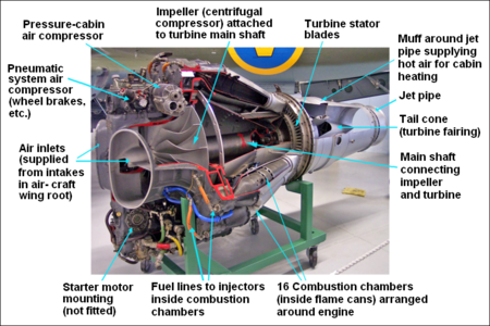
Turboprop engine is more efficient than the turbojet, designed to fly at speeds below 800 km / h (500 mph). Examples of turboprop engines are popular among other Rolls-Royce Dart engines used on aircraft British Aerospace, Fokker 27, etc.2. turbojet ENGINEDevelopment of the best driving machine (Engine) is progressing very rapidly with the development of turbojet engine type, in which the propeller which serves to suck air and generate thrust replaced with a closed high pressure compressor casing, together with the engine combustion chamber and turbine engines. From the picture below visible parts of the engine turbo jet, which consists of a water inlet (airways), fins compressor rotor and stator, the fuel line (fuel inlet), a combustion chamber (combustors chamber), turbine and exhaust ( exhaust). Power thrust (Thrust) 100% produced by the exhaust jet thrust.
Turbojet engine is the simplest jet engine, normally used for high-speed aircraft. Examples of this machine is the Rolls-Royce engine Olypus 593 used for aircraft Concorde. Another type is the Olympus Marine engine that has the power of 28,000 hp (horsepower equivalent to 21 MW) which is used to drive a modern warship with a dead weight of 20,000 tons with high-speed operation.
3. turbofan enginesTurbo Fan is a type of engine which currently enjoys the most modern technology that combines Turbo and Turbo Prop Jet. This machine is actually a by-pass machine in which a portion of the compressed air and supplied to the combustion chamber, while remaining at low densities distributed around the outside of the combustion chamber (by-pass). The air at the same time serves to cool the engine. Power thrust (Thrust), the largest produced by FAN (propeller / blade at the front which is a length), generating thrust by 80% (secondary airflow), and the remaining 20% to exhaust jet thrust (hot gas). At first glance is similar to the turbo fan engine turbo prop, but the propeller in front of the turbo fan has a chamber cover (Casing / Fan case).
Additional foil on Airbus A320 aircraft to maneuverFoil function is to facilitate the air while performing maneuvers.
TYPE OF AIRCRAFT ENGINE
Aircraft Engine TypeAircraft Engine Types: Turboprop, Turbojet, turbofan, turboshaft, ramjet.The aircraft can fly because there is the thrust of the mover (engine) which caused the aircraft has the speed, and speed is of the received aircraft wing airfoil shaped so that the aircraft can be lifted / fly. Election engine based on the size the size of the aircraft. The types of engine (Engine) aircraft are as follows:1. turboprop ENGINEIn the early development of the engine, usually a commercial aircraft using turbo propeller drive systems or commonly called the turboprop. Type turbo prop own system is not much different from the turbo jet, but energy (thrust) generated by the rotation of the propeller by 85%, with round the propeller is driven by a turbine that receives expansion of energy from the burning, the remaining 15% to exhaust jet thrust (hot gas)
Turboprop engine is more efficient than the turbojet, designed to fly at speeds below 800 km / h (500 mph). Examples of turboprop engines are popular among other Rolls-Royce Dart engines used on aircraft British Aerospace, Fokker 27, etc.2. turbojet ENGINEDevelopment of the best driving machine (Engine) is progressing very rapidly with the development of turbojet engine type, in which the propeller which serves to suck air and generate thrust replaced with a closed high pressure compressor casing, together with the engine combustion chamber and turbine engines. From the picture below visible parts of the engine turbo jet, which consists of a water inlet (airways), fins compressor rotor and stator, the fuel line (fuel inlet), a combustion chamber (combustors chamber), turbine and exhaust ( exhaust). Power thrust (Thrust) 100% produced by the exhaust jet thrust.
Turbojet engine is the simplest jet engine, normally used for high-speed aircraft. Examples of this machine is the Rolls-Royce engine Olypus 593 used for aircraft Concorde. Another type is the Olympus Marine engine that has the power of 28,000 hp (horsepower equivalent to 21 MW) which is used to drive a modern warship with a dead weight of 20,000 tons with high-speed operation.
3. turbofan enginesTurbo Fan is a type of engine which currently enjoys the most modern technology that combines Turbo and Turbo Prop Jet. This machine is actually a by-pass machine in which a portion of the compressed air and supplied to the combustion chamber, while remaining at low densities distributed around the outside of the combustion chamber (by-pass). The air at the same time serves to cool the engine. Power thrust (Thrust), the largest produced by FAN (propeller / blade at the front which is a length), generating thrust by 80% (secondary airflow), and the remaining 20% to exhaust jet thrust (hot gas). At first glance is similar to the turbo fan engine turbo prop, but the propeller in front of the turbo fan has a chamber cover (Casing / Fan case).
Engine
/ engine that uses this type of example is the RB211 engine used on the
Boeing B 747 and GE CF6-80C2 used in the DC-10 and P & W SERIES JT
9D. Other
machines that use this type of turbofan engines is the Roll-Royce Tay
on Fokker F-100 (nicknamed the machine fanjet), Adour Mk871 engines used
on fighter aircraft Hawk Mk 100/200 type Jaguar fighter aircraft and
Mitsubishi F-1 used AU Japan.Then the engine high by-pass turbofan engine is applied also to the
CFM56-5C2 used by AIRBUS A340 aircraft and CFM56-3 engines used on
Boeing B-737 serie 300, 400 and 500 which is shared between GE products
with Snecma of France.In military aircraft, turbofan engines were applied among others in
TF39-1C engine used on the giant transport aircraft C-5GALAXI, then GE
F110 used on the F-16.
4. ramjet ENGINERamjet is a type of engine (engine) which if the mixture of fuel and air that sprinkled the fire will be a blast, and when the explosion occurred continuously it will generate an impulse (Thrust). Ramjet engine is divided into four sections, namely: inlet (nozzle divergent) portion of incoming airflow, mixed room is a space a mixture of air and fuel that mixed perfectly, combustor is a combustion chamber equipped with a membrane, which serves to prevent back pressure, the outlet (convergent nozzle) which serves to focus the thrust flow, retain heat and increase the temperature of the combustor.
Technology ram jet is generally developed in rocket / space shuttle. Unmanned aircraft X-43A scramjet engine takes advantage of the future will be used also on the space shuttle. As for the features of the X-434 is used scramjet engine (supersonic combustible ramjet). Scramjet uses new technologies that burn hydrogen with oxygen taken from the air. The oxygen is inhaled and transmitted again at a very high speed.
5. turboshaft ENGINETurboshaft engine is actually a turboprop engine without a propeller. His power turbine is connected directly with REDUCTION GEARBOX or to a shaft (axis) so that the energy is measured in shafthorsepower (shp) or kilowatts (kW).
This type of machine is generally used to drive the helicopter, the main rotor drive or tail rotor (tail rotor) but it is also used in industrial and maritime sectors including power generation, oil and gas pumping stations, hovercraft and boats.Examples of this machine is the GEM / RR-powered 1004 900 shp applied to the Lynx helicopter type and engine Gnome 1,660 shp (1,238 kW) in the Sea King helicopter. While other industry version is 25-30 MW power plant Rolls-Royce RB 211 with 35000-40000 shp.
AIRCRAFT PARTS AND FUNCTIONS
PRIMARY CONTROL SURFACEAs discussed earlier, that there are three things that can be done by the primary control surface are:• Controlling the movement of aircraft,• Controlling the aircraft based on its rotational axis, and• Controlling the best stability.
1. aileron• Located on the wing.• It is the field of control when the aircraft did roll.• Move around the longitudinal axis (the axis that extends from the nose to the tail).• The ailerons are controlled from the cockpit by using the control stick.• The type of stability carried stabilizing aileron is the best in the lateral direction.• opposite aileron movement between left and right, up or down deflection.
How does the aileron ??
Pictured above is the image plane is viewed from the tail.If a pilot wants to do a roll or bank or rolled right, then carried by the pilot are: moving the stick control or steering levers to the right direction, so mechanically there will be a movement in which the aileron to the right to move up and aileron left moves down. On the wing right where aileron up will be a reduction elevator (lift) this is because the ailerons rise causing air flow velocity at the upper surface of the wing is reduced (because ideally airflow over the airfoil faster than the lower surface, causing the elevator) so that the wings right lose lift (adoptive style) which caused the right wing down. While on the left wing, aileron which causes the air pressure drops accumulate and result in the left wing to rise. Vice versa if the pilot wants the plane roll to the left.
2. ELEVATOR• Located on the horizontal stabilizer.• It is the field of control when the aircraft did pitch (pitch up or down).• Moving the lateral axis (the axis that extends along the wing).• Elevators are controlled from the cockpit by using the control stick.• The type of stability carried stabilizing aileron is the best in the longitudinal direction.• Movement of the elevator at the same between the left and right, up or down berdefleksi.
How does the elevator ??
If the pilot wants conducting plane pitch up or down (movement raise and lower the nose). It is done by moving the control stick in the cockpit to the front or to the rear. If we want the pitch up (nose up) then the pilot will move the control stick it to the back (towards the body of the pilot) will receive a response to the rise elevators simultaneously. With the rising elevator then a decline in aircraft aerodynamic forces that pressed tail down so that the nose will raise or increase. The converse if the pilot wanted the pitch down, then the control stick will move forward that will make the elevator move downwards so that the tail gets the force pushing upward and causes the nose down.
3. RUDDER• Located on the vertical stabilizer.• It is the field of control when the aircraft did yaw.• Move the vertical axis (perpendicular to the longitudinal axis of the center of gravity of the aircraft).• Rudder is controlled from the cockpit by using the rudder pedals.• The type of stability carried stabilizing aileron is the best in directional direction.• The movement of the rudder deflection to the left or right.
How does the rudder ??
Rudder works with intermediaries mechanical system called rudder pedal. As well as the brake or gas pedal on a car. There are two pedals, namely the left and right respectively to the left and right yaw movement.If the pilot wants the plane yaw to the left then the pilot will be pressing / stepping on the left rudder pedal, mechanically will be interpreted rudder deflection to the left. What happens is raised aerodynamic forces pressing the rudder surface deflection, so that the tail will move to the right and the nose will move to the left. Then the plane will yaw to the left.Conversely, if will yaw to the right then the rudder pedal is stepped on the right.
So what if they want to maneuver, turn (turn) while, climb, takeoff, descent, etc ??To do this it will be a combination of motion between two or three primary control surface for throttle settings can be added if required movement with speed / thrust increase or decrease thrust.The above explanation is made aircraft movement in three axes of movement is lateral, vertical and longitudinal.
AIRCRAFT FLIGHT CONTROL SYSTEM (SYSTEM CONTROL AIRCRAFT)Aircraft
flight control system (AFCS) closely related to flight control surface
(FCS) or the flight control, where FCS respond to any setting / movement
performed by the pilot in the cockpit through a system of
interconnected then moving mechanical system to perform movements on the plane (yaw, bank / roll, pitch up or down).So in a nutshell, AFCS is an attitude control system to fly a plane by moving the FCS as a control field.Then what is meant by the FCS itself ??FCS is a control surface that can move or be moved to change an air
flow up pressure against FCS could affect the movement of the aircraft
itself.Any FCS in the air ??There were 2 FCS we know the air1. Primary control surface, the primary control surface on the aircraft.As for the control field is:• Aileron, a control field located at the wing / wings.• Elevators, a control field located on the horizontal stabilizer.• Rudder, a control field located on the vertical stabilizer.2. Secondary flight control surface, can be regarded as an additional
control field that aims to help the performance of the primary control
surface and the movement of aircraft when flying, takeoff or landing.Which is included in the secondary FCS, namely:• Slat• Spoiler• Trim tabs• Flaps• Variable-sweep wingWhether the plane should have all the control surface ??For primary control surface ,,, we answered YES ...Because the primary control surface is the primary control surface to
control the aircraft in the movement (movement), the rotation axis
(axes) and its stability (stability).But for a secondary control surface that is optional, depending on the type of aircraft that is based on MTOW. For small aircraft generally used only spoilers or trim tabs only. But
for large aircraft requires an additional control surface to facilitate
air movement itself is also to facilitate the pilot to control the
aircraft both in flight conditions, takeoff, landing or movement on
land.
What is meant by the power plant or engine is the driving force or
supplier air and electrical system, and other support equipment that
is in the best instance air conditioning system (AC), heating system,
etc.To carry out these functions, the aircraft engine have on temperature, power, pressure (pressure), and extreme speed. For that engine to be reliable and safe to operate in these conditions.• Lightweight, why should light ?? Since the weight of the engine will add to the empty weight of the
airplane (empty weight), which means a reduced payload aircraft.• Easily Small and streamlined, which means that must meet the
following criteria: • Reliable (reliable), as the best engine must be needed is a small engine but has a great power and a
streamlined shape.Why is that ??Because
of the greater surface of the engine will also produce a great drag,
reducing power generated and certainly an impact on fuel wastage. Thus the engine cowling fitted da nacelle as engine cover that reduces drag.• Repairable, in this case the engine must be repaired / easily corrected.• Fuel efficient, efficiency is certainly quite important where the
aircraft should be able to cover the distance (range) that as far as
possible with low fuel consumption.• Able to be operated on aircraft flying height.
Engine aircraft is generally divided into two categories, namely:1. Piston engine, in general, always using a piston engine propeller.
2. Turbo engine, comprising: an air intake, compressor, combustion chamber, turbine and exhaust nozzle.
The turbojet engine to differentiate into:• Turbofan, used commonly in civil transport aircraft or subsonic aircraft.
• Turboprop, like a piston engine, turboprop using propeller settings.• turbo shaft, used on helicopters.
• Turbojet, this engine is used for supersonic aircraft in military fighter aircraft.
TAIL GROUPTail
group or empennage on the aircraft tail section covers the entire
surface both fixed (fixed) and mobile / movable (controlable). Which includes a fixed surface is horizontal stabilizer and the
vertical stabilizer, while the moving parts include elevator, rudder and
trim tabs.For details, let us look at the following picture:
Empennage serves to provide stability to the aircraft flight dynamics and control of the plane, with pitch and yaw movement.• Vertical stabilizer, the tail upright and still, where there is a rudder and trim tabs.• Rudder, the part that can move / to deflection that is located on the vertical stabilizer. Rudder is used to control the direction of flight in the air with a vertical axis yaw movement.• Horizontal stabilizer, ie the horizontal tail section and still, where there is an elevator and trim tabs.• Elevators, namely the steering found on the horizontal stabilizer. Elevator moves in tandem to control the movement of pitch / her nose up and down the plane in its lateral axis.• Trim tabs, which is a small field located on the control surface that serves to balance and reduce pressure on the wheel.
Empennage serves to provide stability to the aircraft flight dynamics and control of the plane, with pitch and yaw movement.• Vertical stabilizer, the tail upright and still, where there is a rudder and trim tabs.• Rudder, the part that can move / to deflection that is located on the vertical stabilizer. Rudder is used to control the direction of flight in the air with a vertical axis yaw movement.• Horizontal stabilizer, ie the horizontal tail section and still, where there is an elevator and trim tabs.• Elevators, namely the steering found on the horizontal stabilizer. Elevator moves in tandem to control the movement of pitch / her nose up and down the plane in its lateral axis.• Trim tabs, which is a small field located on the control surface that serves to balance and reduce pressure on the wheel.
BODY GROUPBody group is the entire part of the fuselage in this case the fuselage and structure constituent.Fuselage or air frame which includes cockpit, cabin passangers, cargo
compartment, accessories and equipment compartment is a major part of
the air crew to support the load, the engine also passangers and cargo
(on the single engine aircraft that is placed in the nose).For the fuselage must be robust, reliable, aerodynamic and has a weight that is as light as possible. Why is that ??That's because the fuselage is the largest part of the plane, which
receives loads and absorb the force that occurs either due to friction
with the air and gravity and other styles that work best due to the
movement itself.An aircraft fuselage composed of structural members, which is the best
compiler structure in the form of frames, bulkheads, formers,
stringers, etc.monocoque TYPE
Generally construction monocoque consists only of former (forming) and bulkheads (anchoring) covered by skin. This construction allows the concentration of a very large force on the skin. In this case the skin must be able to absorb all the force that occurs on the aircraft. This allows the skin to be quickly deformed by these forces.Therefore planes currently using contruction semi-mono coque.SEMI mono coque
As with mono coque construction, only the semi - mono coque construction given additional stringers. Stringer element in the form of liaison between former / frame and the bulkhead that extends in the direction of longitudinal.With this construction, load / load and the forces received by the skin can be distributed to all elements through stringers. So the skin is no longer accepting excessive force because some will be neutralized by all the elements on the aircraft.
WING GROUPwing is the most important part of an aircraft, because the wing generates lift (lift) when it moves to the air stream because of the airfoil.Aside from being a manufacturer of lift, in most aircraft today as the fuel tank (a fuel) and the dependent engine.Before studying the wing and what is contained in the wing, let us understand first in drawings:• Leading edge; the front part of the wing were first exposed to the airflow. In large aircraft are generally in leading edge also has a leading edge flap.• Trailing edge; the rear of the wing, where there aileron, aileron tab, and flap.• Wing root; part wing attached to the fuselage.• Wing tip; is the most distant part of the wing with the fuselage or the very tip of the wing. In the wing tip there is usually an additional form of wing lets or wing tip tanks on specific aircraft types.In small aircraft wing generally only comes with aileron, spoiler and flap. It was considered sufficient for the workload of the pilot and the mechanism is not too heavy.Yet another case with large aircraft, in the absence of additional control areas would make the aircraft uncontrollable or difficult perhaps impossible to control.
control surface:
1. Wing let, an additional field on certain planes to reduce the occurrence of turbulence at the wingtip.
2. Low-speed ailerons, rudder movement as a bank and roll under conditions that slow air movement or in flying condition in which it only takes a little bank.3. High-speed ailerons, aileron is used in conditions where the response requires rapid movement of the aileron on the movement of aircraft bank.
4. The flap track fairing, is the stem / fairing mounted for road or track of the flap so that when the flap was removed then it will follow on track.
5. Kruger flaps, the flaps of which tereletak on the leading edge, which functions as an enhancer wing area and enlarge the elevator, but also simultaneously increase the drag.
6. Slats, a flap which is located on the leading adge with the same functionality.
7. Three slotted inner flap, flap that is located closer to the wing root.
8. Three slotted outer flap, flap that is located closer to the wing tip.
9. Spoilers, its function is to damage the elevator, in the sense that is used normally when after landing to reduce lift.
10. Spoilers-air brakes, the spoiler that serves to reduce lift and increase drag so the air as on the brake because the air motion restrained by drag generated
PART FIVE MAIN AIRCRAFTIn general, aircraft consisting of 5 group or five main parts, namely:
wing group, tail group, body group, landing gear group and power plant
group.We can see in the picture below:
• • Wing group: an aircraft wing section. In this group there are steering wing bank / roll or aileron aircraft named aileron, there is also a component of HLD (High Lift Devices) like flap and slat, but it is also a spoiler and wing lets.• • Tail group: Flight tail / empen nage serves as a stabilizer or stabilizer of the aircraft. The tail group consisting of: the vertical stabilizer, where there is a steering direction / yaw called rudder; and horizontal stabilizer where there are steering pitch up and pitch down named elevators.• • Body group: is part of the fuselage or fuselage. Which consists of the nose section, center section and tail section. The meaning here is the tail section of the fuselage section after section wing, so of course different from the tail group. fuselage itself consists of a structural member that is coated with a skin.• • Landing gear group: LG. Group or undercarriage aircraft landing gear group is composed of a main landing gear or main landing gear and nose landing gear. There are two types of landing gear on a fixed wing aircraft types, namely: conventional landing gear, and tricycle landing gear. While in the helicopter landing gear is a form of wheels, skis or just order the holder to landing on the mainland.• • Power plant group: power plant or a propulsion engine aircraft. Engine itself consists of various types, namely: piston engine and turbojet engine. Turbojet engines can be divided into: turbojet (for fighter aircraft at speeds exceeding the speed of sound), turboprop (on the aircraft propeller), turbo shaft (the helicopter) and turbofan (commonly used on aircraft type of transport).
Posted in: aircraft parts, aircraft parts for sale, aircraft parts, aircraft spare parts, aviation parts, aircraft parts, parts of aircraft, type of aircraft .
X . IIIIII
CATEGORIES AND CLASSIFICATION OF AIRCRAFT


MORE WEIGHT THAN AIRAircraft
heavier than air is called aerodin , which fall into this category is
the autogiro, helicopter, gyrocopter and fixed wing aircraft. Airplane
generally use a combustion engine in the form of a piston engine (with
propellers) or turbine engines (jet or turboprop) to generate the
impetus that drives the air and air movement in the wing generates
thrust upward, which makes this aircraft can fly , As
an exception, fixed wing aircraft also were not using the machine, for
example glider, which only uses the force of gravity and the flow of hot
air. Helicopters and autogiro using machines and spinning wings to generate
thrust upward, and helicopters also use the machine to produce forward
thrust.
MORE LIGHTER THAN AIRAircraft lighter than air called the aerostate, which fall into this category is the balloon and airship. Aerostat using buoyant force to fly in the air, such as that used ships to float on the water. These aircraft generally use gas such as helium, hydrogen, or heated air to produce the buoyant force. Difference between air balloon with air boat is air balloon over to windward, while the aircraft has a propulsion system to nudge forward and control system.
HOW CAN AN AIRCRAFT FLIGHTWhy The aircraft can fly?The aircraft can fly because there is momentum of encouragement horizontal plane engine (Engine), then boost the engine will cause different air velocity below and above the wing. Air velocity above the wing will be greater than under the wings in because mileage layer of air flowing over the wing is greater than the mileage under his wing, the travel time through the layer of air over the wing and under the wings are the same. According to the law Bernoully, airspeed great cause small air pressure. so that the air pressure below the wing becomes larger than the top of the aircraft wing. So there will be lift (elevator), which makes the aircraft can fly,
POWER LIFT AIRCRAFT (LIFT)
Then, the plane should be detained so as not to fall, then? Yes, the aircraft can be airborne by being detained by the lift (elevator) net generated by the entire airframe. Of course, the biggest component which produces the lifting force is part of an aircraft wing (wing). How lift generated? There are three names that should be mentioned here, Mr. Newton, Mr. Coanda and Mr. Bernoulli.Actually, in the world of aviation itself there are two theories hitherto used for these theories can be explained scientifically with simple physics. Here will not be elaborated on 4 main force acting on the aircraft because only discuss the one style that LIFT. Now, whether these two theories? Before getting into the discussion, let us take a peek legitimately advance the theory of the basic formula of air lift.
Lift Basic formula:
 Ket:L = Lift (Lift Style)? = Air Density (air density)CL = Coefficient of LiftS = area of Penampang WingsV = Velocity (Speed)
X . IIIIIII
Aircraft and rocket

Working Principle Rocket
Rocket 2 is divided into liquid and solid rocket rockets. I will explain about the liquid rocket.
Rocket 2 is divided into liquid and solid rocket rockets. I will explain about the liquid rocket.

The working principle of liquid rocket similar to the principle and encouraged a toy balloon. A rocket containing a tank containing liquid hydrogen and oxygen material liquid. Both
of these fuels are mixed inside the combustion chamber so that
combustion occurs that produces hot gas which will gush out through a
nozzle located in the tail of the rocket. There were changes in gas momentum of zero (0) into mv during a certain time interval (Δt). This
produces a force that carried out the rocket on the gas (corresponding
to the equation F = Δp / Δt, the forces acting on an object is equal to
the change in momentum of objects per unit time) with a downward
direction. Newton's
third law suits, a reaction force that worked on the gas in the rocket,
the same magnitude but opposite direction is upwards. Thus, the gas will be doing the upward force on the rocket so that the rocket will be pushed to the top.
If we ignore gravity so that no external forces acting on the rocket system, the principles and encouraged the rocket will fulfill the law of Conservation of Momentum. Therefore, initially the system (the rocket and fuel) silent, then the momentum is equal to zero. after gas gushes out of the rocket, the momentum of the system remains, or in other words out of momentum before and after are the same.
m1 m2 v1 + v2 = 0
m1 v1 = v2 -m2
principle conservation of momentum, the final speed that can be achieved a rocket depends on the amount of fuel that can be carried by the rocket and the speed of the gas jet. Therefore these two quantities are limited it is used rocket stages (mult istage rokets). ie, several rockets were merged together.

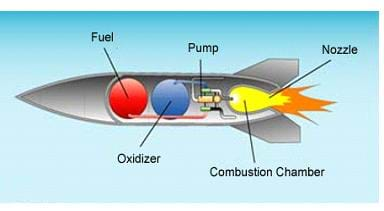

When the fuel has burned out the first stage, the rocket is released. so for continously ,, so that the plane-spacecraft went into space can fly high off the ground. the number of stages or phases depending on the mission requirements footed rocket itself.problems example :
a silinder containing 12 kg of compressed gas. if slinder is opened, the gas will gush out of the mouth of the pipe so silinder will be empty in a time of 1 minute 30 seconds. if gas spurted from the nozzle at a speed of 25 m / s, calculate the force that worked on the gas at the silinder ???1. The first gas momentum equal to 0 (zero) because the gas initially silent in slinder
p1 = 02. The gas momentum at the time out of silinder with a speed of 25m / s is
p2 = m v
= (12 kg) x (25 m / s) = 300 kg m / s3. The gas momentum changes that occur during 1 minute 30 seconds is
F = Δp / Δt
Δp = p2-p1
= 300-0 = 300 kg m / s
F = (300 kg m / s) / (90 sec)
= 3.3 newtonmeans an upward force that lifted the rocket equal to the force that issued the rocket down of 3.3 Newton

A spacecraft rocket, missile, or flying vehicles that get a boost by the reaction of rockets against rapid discharge of fluid material from a rocket engine output. The rocket also contain solid rocket fuel or chemical liquid fuels mutually combine to give great impetus so as to escape the earth's gravity is almost 11km / sec.
The rocket is not only used for military purposes but also for science, communication and even used for humans to land on the Moon. technological advances in many parts of the world as well as vary the size of the rocket.
The rocket is not only used for military purposes but also for science, communication and even used for humans to land on the Moon. technological advances in many parts of the world as well as vary the size of the rocket.
 Figure saturn IIIII
The Saturn IIIII rocket in the world's largest and most powerful ever built in the history of mankind. This is a rocket that is possible for man to land on the Moon. Saturn V high nearly 363-foot-tall 40-story building
N-1

N1 is a fairly powerful rockets and rocket developed by Soviet World to send people to the Moon. But all of these rockets have been destroyed during their test flights. N1 length is about 344.5 meters.
ARES-1

Ares-1 is another US-designed rocket that is currently under development. After retiring from the shuttle, Ares will become human transport to go in space and even to the moon again. Ares-1 has a length of 310 feet and powered by a solid rocket engines during takeoff
DELTA IIII

Delta IIII is a US-designed rockets for the purpose of military and commercial use. This rocket has a height of 206 meters
ATLAS IIIII

Atlas V is a US-made rocket designed to carry heavy loads to be transported into Earth orbit. This rocket has a height of 195 feet and has a total lift of 333 298 kg mass
ARIANE 5
The first test flight Ariane 5, which failed in June 1996, with the self-destruction for 37 seconds after launch because of damage to the control software, which is undoubtedly one of the most expensive computer bugs in history. This rocket has a height of 193 feet
ARIANE 5
The first test flight Ariane 5, which failed in June 1996, with the self-destruction for 37 seconds after launch because of damage to the control software, which is undoubtedly one of the most expensive computer bugs in history. This rocket has a height of 193 feet
SPACE SHUTTLE

Now come here with sophisticated machines, namely space shuttle. Made in the USA, Space Shuttle is being used for shipping cargo into orbit with a medium size and is operated by a crew of seven men. Space Shuttle has a height of 184 feet along
H-IIB ROCKET:
H-IIB is a liquid-fueled rockets made in Japan that provides a launching system for the main purpose of the launch of the H-II Transfer Vehicle (HTV) to the International Space Station (ISS). It has a height of 56m
FALCON IIIIIIIII

Falcon IIIIIIIII is a two-stage can be used to orbit; oil liquid oxygen and rocket-powered launch vehicles manufactured by SpaceX. The rocket is still in development and will be launched in late 2009. This rocket has a height of 178 feet
PROTON

Proton was launched in 1965 and launch systems still in use in 2009, which makes it one of the most successful proponents of weight in the history of space. It has a height of 53m


Tidak ada komentar:
Posting Komentar