
X . I
Definition of IC (Integrated Circuit) and Its Application

Definition of IC (Integrated Circuit) and Applications - Integrated Circuit or IC is abbreviated with Active Electronic Components consisting of a combination of hundreds, thousands or even millions of transistors, diodes, resistors and capacitors are integrated into an Electronic circuit in a small package. The main ingredients that make up an Integrated Circuit (IC) is a semiconductor material. Silicon is a semiconductor material most commonly used in Fabrication Technology Integrated Circuit (IC). In Indonesian, integrated circuit or IC is often translated into Integrated Circuits.

A Brief History of IC ( Integrated Circuit )
Technology Integrated Circuit ( IC ) or Integrated Circuit was first introduced in 1958 by Jack Kilby working for Texas Instruments, half a year later Robert Noyce managed to fabricate ICs with interconnection system on a silicon chip. Integrated Circuit (IC) is one of the most significant technology developments in the 20th century.
Before the discovery of the IC, electronic equipment when it is in general use Vacuum Tubes as a main component was then replaced by transistors having a size smaller. But to set out a series of Electronics cumbersome and complex, requiring a component transistors in large quantities so that the size of the electronic device be produced is large and poorly suited to be the go (portable).
Technology IC (Integrated Circuit) allows a designer to create an Electronic circuit Electronic equipment smaller, lighter with a more affordable price. An IC power consumption is also lower than the transistors. Therefore, IC (Integrated Circuit) has been the top component in almost all electronics devices that we use today.
Without the technology IC (Integrated Circuit) maybe this time we can not enjoy a Portable Electronic devices such as mobile phones, laptops, MP3 Player, Tablet PC, Portable Game Consoles, Digital Cameras and Electronic equipment that is small and can travel anywhere.
Application and Function IC (Integrated Circuit)
Based Applications and Functions, IC (Integrated Circuit) can be divided into Linear ICs, Digital ICs and also a combination of both.Linear ICs
Linear ICs or also called Analog IC is IC, which generally serves as:
Power amplifier (Power Amplifier)
Signal Booster (Signal Amplifier)
Operational amplifier (Operational Amplifier / Op Amp)
Micro Signal Amplifiers (Microwave Amplifier)
RF and IF amplifier (RF and IF amplifier)
voltage Comparator
multiplier
Radio Frequency Receivers (Radio Receiver)
Voltage Regulator (Voltage Regulator)
Digital IC
Digital IC is basically a circuit switching voltages Input and output only has two (2) level of "High" and "Low" or in binary code is represented by a "1" and "0".
Digital IC generally function as:
Flip-flop
Logic gates (Logic Gates)
timer
counter
multiplexer
Calculator
memory
clock
Microprocessor (Microprocessor)
micro controller
It needs to be remembered that the IC (integrated circuit) is an Active Electronic Components sensitive to the effects of Electrostatic Discharge (ESD). Thus, special handling to prevent damage to the IC.
Integrated Circuit (IC) or Integrated Circuit is an important component in any Electronic Equipment. Almost every electronics equipment use. On Today, sophisticated equipment such as mobile phones Electronics, Computer, Audio / Video Player, Televisions, Digital Cameras, Game Consoles and Tablet PC is not out of the use of IC (Integrated Circuit) as a component of the Underlying.
Although it has many advantages and plays a very important in the development of technology and industrial electronics, integrated circuit or IC also has various limitations or weaknesses that would require more as a supporter of Electronic Components circuit designed so that it meets the needs and the desired function.
As one example, the Integrated Circuit (IC) is a component of electronics that can only operate at a low voltage (eg, 5V or 12V). Therefore, if the source voltage is higher than specified, the necessary adapter or a special circuit to lower the voltage and electric current. In general, we can find the adapter as lowering the voltage on a Laptop or Mobile, Power supply that converts 220V voltage in order to provide the source voltage of 5V for Motherboard and Processor Computer. In addition, we can also find many other supporting components Electronic components around the IC (Integrated Circuit) that one of its functions is to provide a source of voltage and current suitable to operate IC.
Here are some of the advantages and limitations of integrated circuit or IC:Excellence / excess IC (Integrated Circuit)
Small size.
Lighter.
The price is cheaper because it can be produced in large quantities and simultaneously within one (1) wafer.
More reliable because it requires no solder connections and interconnects have very little in the Internal IC components.
Consuming less power, this is due to the small size of the IC so that electric power consumption is smaller.
More easily replaced and troubleshooting (improvement) in the event of damage to the electronics circuit.
Suitable for low signal operation.
Can perform functions that are more complex and complicated.
Weaknesses / Limitations IC (Integrated Circuit)
Unable to generate a high power.
Can only operate at a low voltage.
Require to be handled more carefully, the IC is not resistant to rough handling and very sensitive to Electrostatic Discharge (ESD).
Not resistant to high temperatures. Therefore, requiring ventilation or fans and heat sinks to help lower the temperature around the IC.
Not withstanding high voltage overload (Voltage tolerance is very small and limited) because it can damage the internal components of the IC. To determine the characteristics or voltage ICs are suitable, necessary Datasheet of IC manufacturers in designing (design) Circuit Electronics.
Requires external connections to the inductor and transformer components (transformers) to perform functions related to and Electromagnetic Induction. This is because the IC technology is not currently possible to re-integration-the inductor and transformer into the Internal IC.
Requires external connections to components Capacitors for more capacitance value of 30pF.
X . II
reviews advanced integrated electronics
Electronic Warfare Systems

Integrated electronic to be concentration :
- Electronic Attack (EA)
- Electronic Protect (EP)
- Electronic Support (ES)
Electronic Attack (EA) Subsystems

Electronic Attack (EA) or Electronic CounterMeasures (ECM) products and services provide the components, modules, and subsystems that are used in communications jamming, Integrated Air Defense Systems (IADS) suppression, Directed Energy Weapon (DEW)/LASER attack, expendable decoys (chaff and flares ), and Radio Controlled Improvised Explosive Device (RCIED) systems.
These pod based Solid State and Travelling Wave Tube transmitters, comprised of amplifier, antenna, power supply, control and cooling subsystems, are characterised by wide operating bandwidth, high output power and high reliability.Communications Countermeasures consist :
integrated antenna/radome and Low Band Transmitter, designed to protect strike aircraft, ships, and ground troops by disrupting enemy radar and communications.
Exciters for Radar and Communications consist :
Exciter expertise encompasses both radar and communications waveform generation using both analog and digital techniques. Signal generation via Direct Digital Synthesis allows fast tuning, programmability and flexible modulation.
High Power Transmit Antennas consist :
to be developed very high power antennas for fixed and ground mobile applications. These antennas have been used in jamming systems, threat simulators and communication systems.
Radar Countermeasures consist :
to be Tactical Jamming System. Key to achieving cost effective long range standoff jamming was development of technology to allow coherent RF combining of multiple high power TWT Amplifiers.
Electronic Protection (EP) SubSystems

Electronic Protection (EP) to be products and services protects personnel, facilities, and equipment from any effects of friendly or enemy use of the electromagnetic spectrum that degrade, neutralize, or destroy friendly combat capability.
Electronic Protect (EP) products and service
protects friendly forces from the effects of Electronic Attack (EA)
(friendly and/or adversary). EP solutions include spread
spectrum technologies, EMissions CONtrol (EMCON), and low
observability.
Electronic Warfare Self Protection (EWSP) products and services offer a suite of countermeasure solutions for land, sea, and air platforms for the purpose of protecting the platform from weapons fire. the products and services include an extensive suite of Radar Warning Receivers (RWR) fitted to fixed and rotary wing aircraft.
Electronic Surveillance (ES) SubSystems

Electronic Warfare Support (ES) products and services provide an operational commander the ability to search for, intercept, identify, and locate or localize sources of intentional and unintentional radiated ElectroMagnetic (EM) energy.
Electronic Surveillance products and
services is immediate threat recognition, targeting, and other
tactical actions such as threat avoidance and homing.
However, the same assets and resources that are tasked with
Electronic Surveillance can simultaneously collect intelligence
that meets other requirements.
ES products and services include equipment that can be used for Signals Intelligence (SIGINT) - the process of analyzing and identifying intercepted frequencies (e.g. as a mobile phone or RADAR) and identifying frequency, bandwidth, modulation, polarization, etc.
Electronic Solutions has developed and deployed
Electronic Surveillance Subsystems on multiple fixed wing and
rotary wing aircraft, attack class submarines, missiles and ground
mobile vehicles.
The expertise encompasses vehicle integration for optimum installed performance, modeling and simulation for design optimization, and superior design capability in all radome, antenna and RF components.
Electronic Warfare (EW) SubSystems

Electronic Warfare (EW) products and services, used to control the Electro Magnetic (EM) spectrum, can be applied from space, air, land, and maritime by manned and unmanned systems, and can target humans, communications, radar, or other assets.
Electronic warfare (EW) refers to any action involving the use of the ElectroMagnetic (EM) spectrum or directed energy to control the spectrum, attack an enemy, or impede enemy assaults via the spectrum.
EW solutions are to deny the opponent the advantage of, and ensure friendly unimpeded access to, the EM spectrum
EW products and services span the three major EW subdivisions: Electronic Attack (EA), Electronic Protection (EP), and Electronic warfare Support (ES)
Low Band Transmitter-Antenna Group (LBT-AG), The LBT is designed to protect strike aircraft, ships, and ground troops by disrupting enemy radar and communications. It is flown on US Navy EA-6B Prowler and EA-18G aircraft and Marine Corps EA-6B aircraft, and has been used in combat operations.
X . III
flashback of the past integrated electronics
I . introduction microcontroller

Introduction of Micro controller. During the 40 years since it was first introduced, the micro controller has undergone much development. Various
technologies, functionality, and peripherals that are applied to these
components makes micro controllers currently outstanding have a lot of
variety. There have been countless applications that are created using a
micro controller, ranging from daily life to up to an industrial scale.Intro to micro controllers
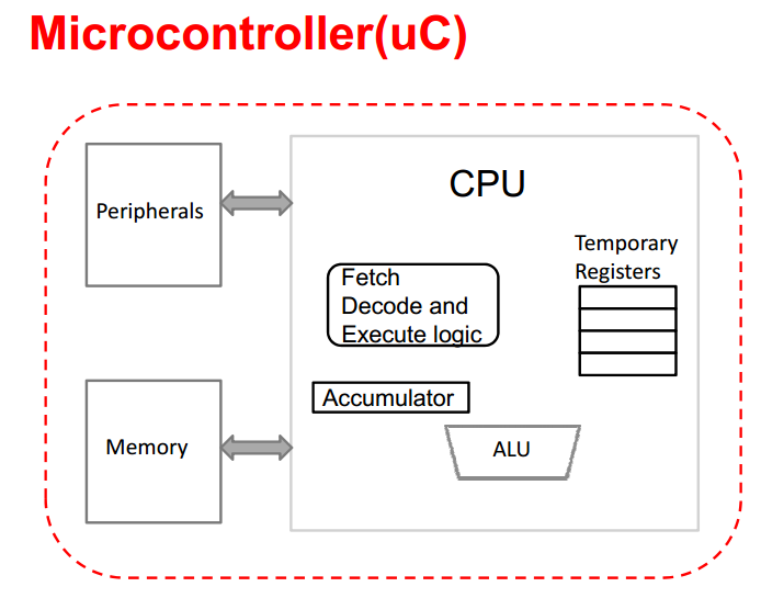
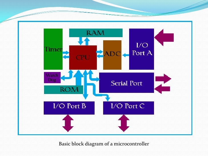
The micro controller is a micro computer within a single chip. Micro controller
combines CPU, ROM, RWM, I / O parallel I / O series, counter-timers,
and the clock circuits in a single chip as shown in Figure 2. In other
words, the micro controller is a digital electronic device that has
inputs and outputs as well as control with a program that can be written and erased in a special way. The workings of the actual micro controller to read and write data. For example, imagine yourself as you begin to learn to read and write. When
you are able to do it then you can read any good books, short stories,
articles, and so on, and you also can write things otherwise. Similarly,
if you are adept at reading and writing data then you can create a
program to create a system of automatic settings using a micro controller
according to your wishes.
As with microprocessors, micro controllers is a device designed for the needs of the public. The main function of the micro controller is to control the machine working or the system using a program stored on a ROM.
Micro controller
is a chip inside the computer that is used to control electronic
devices, which emphasize efficiency and cost effectiveness. Literally can be referred to as "little control" where an electronic
system which previously was often require supporting components such as
T T L and CMOS IC can be reduced / minimized and ultimately centralized
and controlled by the micro controller.
Mikroconroler
used in products and equipment are controlled automatically, such as
engine control systems, remote controls, office machines, household
appliances, heavy equipment, and toys. By
reducing the size, cost, and power consumption compared to designs
using microprocessor memory and input devices separate output,
micro controller presence make electrical controls for different process
more economical. With the use of this micro controller then:
electronic system will be more concise,
electronic systems design can be done more quickly because most of the system is software that is easily modified,
disorders that occur more easily traced because the system is compact.
However,
the micro controller does not fully reduce TTL and CMOS IC components
are often still required for high-speed applications or just increase
the number of input channels and output (I / O). In
other words, the micro controller is a mini version or micro structure of
a computer for micro controllers already contain some peripherals that
can instantly be used, for example, a parallel port, a serial port, a
comparator, the conversion of digital to analog (DAC), analog to digital
conversion and so only use the system minimum simple.
In
order for a micro controller to function, the micro controller requires
external components are then referred to the minimum system. To make the system at least minimum required clock and reset the
system, although in some micro controllers already provides the system's
internal clock, so that without any external circuit micro controller can
operate.
To
design a micro controller based system, we need hardware and software,
are the minimum system micro controller, software programming and
compilers, as well as the down loader. What is meant by minimum system is a micro controller circuit that can already be used to run an application. A micro controller IC would be meaningless if the only stand-alone. Basically, an AVR micro controller minimum system has the same basic principle and consists of four parts, namely:
processors, the micro controller itself,
reset circuit so that the micro controller can run the program from the start,
clock circuit, which is used to give the pulses in the CPU,
power supply circuit, which is used to provide resources.
In
micro controller certain types (eg AVR), points 2 and 3 are already
available in the micro controller with a frequency that has been set by
the manufacturer (usually 1MHz, 2MHz, 4MHz and 8MHz), so users do not
require additional circuits. However,
if users want to design a system with certain specifications (eg
communication with a PC or mobile phone), then the user must use a clock
circuit in accordance with the characteristics or HP PC, usually using a
11.0592 MHz crystal, to generate a proper communication with the device
baud rate which is aimed.
family AVR
In general, the micro controller is divided into three large families on the market, namely: MCS51 Family, Family AVR and PIC Family. Each family has its own characteristics and character respectively. In this time the training will be discussed AVR family.
Micro controller Alv and Vegard's Risc processor, or often abbreviated AVR, an 8-bit RISC micro controller. The use of RISC technology have led to most of the instruction code is packaged in a single clock cycle. AVR micro controller is the type most commonly used in electronics and instrumentation.
AVR generally can be grouped into four classes. Basically the differences of each class is in memory, peripherals, and functions. The fourth class is AT tiny family, family AT90Sxx, family ATMega, and AT86RFxx.


ATMEGA 8535/16/32
ATMEGA series are micro controller-based AVR 8-bit architecture. Physically the three types of the same microcontroller and can be used at the same minimum system anyway. The third difference is the specification of the micro controller memory used. The following comparison table third the micro controller.


ATtiny 2313
ATtiny2313 a series micro controller with 8-bit AVR architecture. Although it has the same architecture, different from ATMEGA ATtiny in terms of features and memory. Compare ATMEGA 8535 which has 8 KB of flash memory with ATtiny memori flash 2313 that have only amounted to 2 KB. In features, ATMEGA include ADC features in one package IC while ATtiny 2313 does not have these features. In addition ATtiny maximum speed of 2313 to about 8 MHz only, in contrast to 16 ATMEGA series are capable of up to 16 MHz. Micro controlerATTINY pin configuration of 2313 can be seen in Figure below.


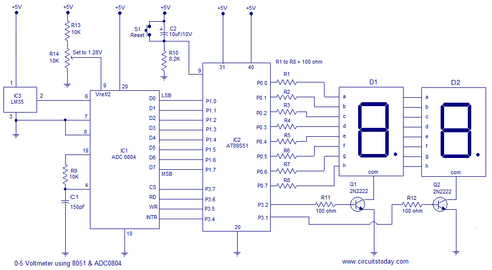
Configuration Pin Microcontroller IC AT89S51
Pin is the physical leg of an IC AT89S51. Each pin has a function and its own characteristics that must be considered. AT89S51 has several pins, is functioning as input / output (I / O), is functioning as a control path, and there is also a function as the address bus or data bus. AT89S51 the pin configuration can be seen in the picture
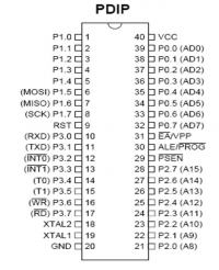

The following is an explanation of pin-pin AT89S51:
a. Pin 1 to 8Pin 1 to 8 is the first port that becomes a channel (bus) two-way 8-bit input or output. With internal pull-ups that can be used for various purposes and can control four TTL inputs. This port is also used as a channel address at the time of programming and verification.
b. Pin 9 (RST)A reset input (active high) for two cycle engines.
c. Pin 10 toPin
17 is a third port which is the channel (bus) input / output 8-bit
bi-directional internal pull-ups that have alternate functions. These alternate functions are presented in table 2.18.When
a logic 1 is given to the port 3, then the internal pull-up will set
the port on the condition of high and port 3 can be used as an input
channel. When an alternative function is not used, then this function can be used as a versatile 8-bit parallel port. In addition, most of the port 3 can function as a control signal during the programming process.Table 2:18 alternate function port 3Alternative port pin descriptionP3.0 RXD serial port to receive dataP3.1 TXD To send data serial portP3.2 INT0 'External Interrupt 0P3.3 INT1 'External Interrupt 1P3.4 T0 Input external timer / counter 0P3.5 T1 Input external timer / counter 1P3.6 WR 'Paths external data memory write strobeP3.7 RD 'Paths external data memory read strobe
d. Pin 18 and 19This path is the input to the amplifier oscillator high amplifier gain . This micro controller has all the necessary oscillator circuit on a chip, but a series of crystal. In addition XTAL 1 can also be used as input to the inverting
oscillator amplifier and input to the internal clock circuit whereas
XTAL 2 is output from the inverting oscillator amplifier.
e. Pin 20A ground voltage source by the symbol GND
f. Pin 21 to 28This pin is a 2 port which channels (bus) input / output bidirectional 8 bit with internal pull-ups.
g. Pin 29A control signal for accessing external program memory into the
channel (bus) during the process of giving up or taking instructions
(fetching).
h. Pin 30Retaining an external memory address (on port 1) for access to external memory
i. Pin 31External Access Enable (EA) is a control signal for reading the program memory. When set low (L), the micro controller will execute all instructions
from external program memory, while if set to high (H), the
micro controller will execute instructions from internal program memory.
j. Pin 32 to 39This pin is a port 0. Port 0 is one of the port that serves as a general-purpose I / O with a width of 8 bits. Port 0 consists of P0.0-P0.7. Aside from being a track I / O Port 0 also serves as multiplexed the address / data bus.
k. Pin 40Is a source of positive voltage VCC by the symbol.
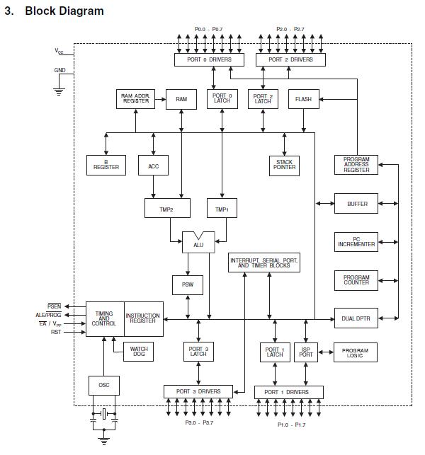
Structure Elucidation IC AT89S51 Microcontroller Memory - Memory is essentially serves to 'remember' that store information. AT89S51 has a memory structure comprising:
Internal RAM, a memory of 128 bytes are typically used to store variable or data that is temporary. This memory can be accessed using RAM address register.
Flash PEROM, the memory used to store instructions, instructions MCS51.
21 Special Function Register (Special Function Register), a memory that contains registers that have special functions.
This special function registers consist of:1. accumulatorThis register is located at address E0H. Almost all the operations of arithmetic and logic operations always use these registers. For pickup and delivery of data to the external memory is also required these registers.
2. Register B.Has the same function as the accumulator.
3. Stack PointerStack Pointer (SP) is an 8-bit registers located at address 81H. The contents of the Stack Pointer is an address and data stored on the stack. The process associated with the stack is usually done by instructions Push, Pop, ACALL, and LCALL.
4. Data PointerDPTR is generally used to access an address in the external memory. Example: mov A, # 01H
Mov DPTR, # 2000H MOVX @ DPTR.A
Listing the above function to write the data into the address 01H 2000H. First data is loaded into the accumulator 01H then DPTR is used to write the address of the data storage is filled with 2000H. Lastly, the contents of accumulator A is stored to the memory location indicated by DPTR.
5. Register PortA register that represents the port address.6. Register TimerA register used to set the timer operation.
7. Register Port SerialA register used in the process of serial communication.
8. Register InterruptionsA register used to set the interrupt process.
9. Power Control RegisterPower Control Register (PCON) contains some kind of control bits.
Microcontroller AT89S51merupakan CMOS 8-bit microcontroller with 4 Kbyte in-system programmable Flash memory. AT89S51 tech high-density nonvolatile memory of ATMEL, the memory contents can be recharged or removed many times and is compatible with industry standard 80C51 microcontroller both IC pin and set instructions.
Specifications AT89S51 among others:
9 4 Kbytes of In-System Programmable (ISP) Flash memory with the ability
1000 times read / write.
9 The working voltage 4 - 5.5 V
9 Working with the range of 0-33 Hz
9128 x 8 bits internal RAM
9 32 channels of I / O that can be programmed
9 Two 16-bit timer / counter
9 6 interrupt sources
9 Channel Full-Duplex serial UART
9 Watchdog timer
9 Dual Data pointer
9 ISP flexible programming mode (byte and page mode).
II . Introduction microprosessor
Microprocessors are part of a computer system assigned to conduct simple calculations and executes the commands to be executed. In short, the microprocessor is the heart of a computer system. Here's an example of one of the microprocessors:

figure microprosessor
The task of a microprocessor there are three, namely:
Arrange the transfer of data between itself and a memory or I / O
Working on the calculation system and simple logic
Taking a simple decision on an act
The
reliability of a microprocessor views from its ability to execute
thousands and even millions of instructions per second of a program or
set of instructions placed in memory. Data transfer speed microprocessor unit called bits. The
first is the Intel 4004 microprocessor speed transfer 4 bits and the
speed of execution of 50 Kilo Instruction per Second (KIP). Simple arithmetic and logical processes that do microprocessors are
Addition, subtraction, multiplication, division, operating OR, AND, NOT,
NEG, Shift and Rotate.
In a microprocessor-based computer system, there are three paths into a process flow.
The data bus to stream data from / to the microprocessor
Bus Address / Address functioning put address a process from / to memory or I / O
Bus Control which controls the process of instruction that occurs from / to the microprocessor.
Is illustrated in the following figure:

Bus address requested memory address of a memory or I / O address of a device I / O. If the I / O addressable, then the address bus will have a 16 bit address from 0000h to FFFFh. This address is also called port number. Port number will choose one of the 64K (65535) device I / O is different. If the addressable memory address, then the address bus will contain the memory address. The width of the memory address depends on the type of microprocessor that is used (again in units of bits).
The data bus to stream data from / to the microprocessor to / from the destination memory address or address I / O purposes. Large data bus transfer rates vary according to the microprocessor used.
Bus Control contains instructions governing the operation if it was read or write. There are four types of control are:
MRDC (Memory Read Control) which states that the transfer of data from memory to the microprocessor
MWTC (Memory Write Control) which states that the transfer of data from the microprocessor to the memory
IORC (I / O Read Control) which states that the transfer of data from the device I / O to the microprocessor
IOWC (I / O Write Control) which states that the transfer of data from the microprocessor to the device I / O.
Relationships between the three is, for example, if we want to transfer data from the microprocessor to the memory. First, the address bus will be put address on the destination address. Then the control bus will signal MWTC = 0. Then the data bus will transfer the data to the destination address.
Microprocessor is an IC (Integrated Circuit) which is used as a brain / main processor in a computer system.
Microprocessors are the result of the growth of the semiconductor. The processor is a chip that is often called "Micro prosessor" which is now the size has reached gigahertz. The measure is a matter of processor speed in processing data or information. Brands are more outstanding dipasatan processors are AMD, Apple, VIA Cyrix, IBM, IDT, and Intel.
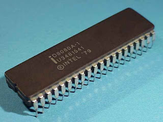
Microprocessor first introduced in 1971 by Intel Corp., the Intel 4004 microprocessor which has a 4 bit architectures. With the addition of some peripherals (memory, device I / O, etc.) Microprocessor 4004 transformed into a small computer by intel. The microprocessor then developed further into 8080 (arsitechtur 8bit), 8085, and then 8086 (arsitechtur 16bit).
microprocessor 4004
Intel launched the world's first microprocessor, the 4-bit 4004, designed by Federico Faggin. Microprocessor 4004.Processor starting in 1971 where Intel issued its first processor is in use on a calculating machine buscom. It is a discovery that started entering into the system intelligent machines.


4004 microprocessor has a PMOS transistor 2250, 4 bits of data handling, and can execute 60 thousand operations per second. Microprocessor 4004 is one of the series IC to the calculator component: 4001: 2048-bit ROM memory; 4002: RAM memory
Microprocessor 8008
In 1972, Intel issued a 8008 microprocessor speed arithmetic 2-fold from the previous MP. MP is the first 8 bit microprocessor. Mp is also designed to do one job. The young Bill Gates and Paul Allen try to develop a programming language for the chip, but it was still not strong enough.

 Microprocessor 8080
In 1974 Intel Microprocessor re-issued the latest in the series 8080, with 4,500 transistors that have 10 times the performance of its predecessor. In this series of microprocessors intel changes multi voltage be triple voltage, NMOS technology in use, faster than the previous series taking PMOS technology. This microprocessor is the brain first for a computer named altair. At this time addressing the memory is up to 64 kilobytes. the velocity up to 10X previous mp.

This year also appeared Mp from other manufacturers such as Motorola MC6800 -1974, -1976 Zilog Z80 of (the two rivals), and other prosessor2 6500 series artificial MOST, Rockwell, Hyundai, WDC, NCR and so on.
1975: Chip 8080 found the first PC application in the Altair 8800, while revolutionizing the PC. Gates and Allen Altair successfully develop basic language, which later became Microsoft Basic, for 8080.

Microprocessor 8086
In 1978 Intel introduced a 16-bit microprocessor 8086. Processor 8086 is the first 16 bit cpu. But at this time there are still many in use mainboard sandard 8 bits, because the motherboard 16bit is expensive.
In 1979 intel processor redesign is thus compatible with the mainboard 8 bit which was named 8088 but logically in the call 8086sx. IBM computer companies using this 8086sx processor for computers because it's cheaper than the price of 8086, and also can use the mainboard processor scars of 8080.
 The technology used on this processor is also different from the 8080 series, where the 8086 series and Intel technology 8086sx HMOS.
The 8086 microprocessor has a 16-bit data bus, so it can write or read data to / from memory or input / output ports of 16 bits or 8 bits each time, the microprocessor has a 20 bit address bus, so it can address 220 = 1,048,57626 location memory.
 In 1980 Intel introduced the 8087 math co-processor.
And in 1981, IBM chose 8088 to run its PC. An Intel executive then speak of it as "the first major victory Intel."
Microprocessor 80286
In 1982 Intel introduced the 286 microprocessor or better known by the name 80286 is a processor that was first able to recognize and use the software used for the previous processor. In the 80286 microprocessor has 134,000 transistors
This microprocessor also has a processor 16 bit. Processor progress relatively large compared to the chip-chip clock first generation . Frekuensi improved, but the main improvement is the optimization of handling 286 action . Mikro prosesor produces more work per clock tick than 8088/8086. At the initial speed (6 MHz) working staged four times better than 8086 at 4.77 MHz.
 Figure Mikroprossesor 80286
In 1984 the latter introduced microprocessor with a clock speed of 8.10, and 12 MHz is used on the IBM PC-AT. And that was running MS-DOS, later became a standard PC for nearly 10 years.
803861985 Microprocessor: Intel out of the dynamic RAM business to focus on microprocessors, and finally he issued the 80386 processor, a 32-bit chip with 275,000 transistors and the ability to run multiple programs at once.
 Figure Microprocessor 80386
1986: Compaq Computer catapulted IBM PC based on 80386.
1987: VIA Technologies was founded in Fremont, Calif., They will on sale x86 core logic chip sets.
80486 Microprocessor launched 80486Pada 1989, with 1.2 million transistors and a built-in math co-processor.
Intel has predicted the development of multi core processors sometime in the 2000s.
The Intel486 ™ processor generation really meant you go from a command-level computer into point-and-click computing. "I could have a color computer for the first time and do desktop publishing at a significant speed," recalls technology historian David K. Allison of the Smithsonian's National
 Figure Mikroprossesor 80486
Museum of American History. The Intel486 ™ processor was the first to offer a built-in math coprocessor, the which speeds up computing Because it offloads complex math functions from the central processor.

Intel® Pentium® Processor
In 1993, 3.1 million transistors, 66-MHz Pentium processor with super scalar technology launcher .The Intel Pentium® processor allowed computers to more Easily incorporate "real world" of data such as speech, sound, handwriting and photographic images. The Intel Pentium brand, Mentioned in the comics and on television talk shows, Became a household word soon after introduction.

Image Intel® Pentium® Processor
The new generation of processors that can handle various types of data such as voice, sound, handwriting and photos.
Intel® Pentium® Processor ProReleased in the fall of 1995 the Intel® Pentium® Pro processor is designed to fuel 32-bit server and workstation applications, enabling fast computer-aided design, mechanical engineering and scientific computation. Each Intel® Pentium Pro processor is packaged together with a second speed-enhancing cache memory chip. The powerful Pentium® Pro processor boasts 5.5 million transistors. 
Processor is designed for use on server and workstation applications, created to process data quickly, this processor has 5.5 Million transistors are embedded.
 Pentium II processor is a processor that incorporates Intel MMX is designed specifically to process video data, audio, and graphics efficiently. There are 7.5 million transistors integrated in it so that with this processor PC users can process a variety of data and use the internet better

 Processor made for the needs of the application server. Intel when it wants to meet its strategy that wants to provide a unique processor for a particular market.
Image Intel® Pentium II Xeon Processor
Intel® Celeron® Processor
1999: VIA acquired Cyrix Corp. and Centaur Technology, a maker of x86 and x87 co-processor


Processor Intel Celeron has a shape and formfactor same Intel processor type Pentium, but only with instructions fewer, L2 cache is smaller, the speed (clock speed) is slower, and the price is cheaper than an Intel processor Pentium types. With the release of Intel's Celeron processor is then returned to give a processor for a particular market.
With the release of Intel's Celeron processor is then returned to give a processor for a particular market.
Intel re-penetrated market servers and workstations by issuing a series of Pentium III Xeon but the kind that has 70 SIMD command. The advantages of this processor is that it can speed up the processing of information from the system bus to the processor, which also boosts performance significantly. The processor is also designed to integrate with other similar processors.
Intel® Pentium® 4 Processor
In 2000 Debut Pentium 4 processor with 42 million transistors.
Processor Intel Pentium IV is a product that speeds up the process is able to penetrate up to 3:06 GHz speeds.
Quad2007 Intel Core 2 Processor: Intel Core 2 quad processors introduced in January.
Processor for desktop type and is used in people who want more power than the computers that he had to have two cores at 2.4GHz configuration with 8MB of L2 cache (up to 4MB, which are accessible for each core), 1.06GHz front-side bus, and thermal design power (TDP).
X . IIII
development of integrated electronics in the next period to introduce nanoprocessor and nano controller
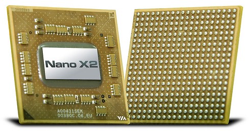
VIA's Nano X2 dual-core processor
Intel and Advanced Micro Devices are not the only ones innovating in the x64 chip racket. VIA Technologies has carved out a niche for itself for low-powered chips suitable for netbooks, small form factor PCs, micro servers, and other embedded devices, and is double-stuffing its sockets with the QuadCore X4 chips to better compete with Intel's Atom and AMD's future "Bobcat" processors.The QuadCore X4 that crams two of its latest dual-core Nano X2 processors, which were launched in early January and which were supposed to start shipping in the first quarter, onto a single chip package. This is cheaper and easier than designing, taping out, and manufacturing a real quad-core processor and is in fact what Intel itself did for its early dual-core "Paxville" Xeon processors from late 2005 (before the Core architecture was available) and what AMD is doing with its current Opteron 6100s, which are really two Opteron 4100s in a single fat socket.
The original Nano processor is based on VIA's Isaiah 64-bit architecture, which debuted in early 2008 with a single-core design. The Nano chip was initially deployed using a 65 nanometer process from either Fujitsu or Taiwan Semiconductor Manufacturing Corp, who bake VIA's chips, but with the X2 dual-core variants, VIA is shifting to 40 nanometer processes.
The Isaiah cores have a superscalar core design that features out-or-order execution; the core has two pipelines fed by eight branch predictors. The Isaiah core has seven execution units, including two integer units, two store units, one load unit, and two media units that have a 128-bit wide data path; the media units can do up to two double-precision or four single-precision operations per clock. (The first unit can do various floating point operations, but the second unit can only do multiplies.)
The Isaiah are designed to have clock speeds that scale from 800MHz to 2GHz and use a front side bus architecture called V4 by VIA that is like old the FSB used by Intel in its Xeon and Pentium chips; that VIA V4 bus can scale from 533MHz to 1.33GHz. Each Isaiah core has 64KB of L1 data cache, 64KB of L1 instruction cache, and 1M of L2 cache.
The chip also has a feature called Padlock, which includes a random number generator and an AES encryption/decryption engine. And importantly, VIA has also reverse-engineered Intel's VT virtualization extensions, so hypervisors can run atop the Isaiah cores.
The Nano chips are pin-compatible with prior VIA C7 standard and Eden low-power processors and their VX900 and VN1000 chipsets. The Nano X2, Eden X2, and now QuadCore X4 chips can similarly plug into the same sockets and use the same chipsets.
The Nano X2 chips are the standard version of the X2 design, and mysteriously VIA has not released their clock speeds yet and Mini-ITX and Nano-ITX system vendors don't seem to have the parts yet, either, although they were supposed to have them ready for sale in systems by the end of the first quarter.
The Nano X2 E-Series variant is aimed at low-power operation and has clocks that spin at 1.2GHz or 1.6GHz and are aimed at embedded Linux and Windows Embedded Standard 7 applications. The Nano X2 E-Series chips and system boards are sampling now at 1.2GHz and 1.6GHz and are expected to ship in the second quarter.
The Eden X2 is a geared down version of the Nano X2 that is designed for fanless operation; it is not clear when this chip will start sampling or be available, or what clock speeds it will run at, but VIA has said that it maxes out at five watts of thermal dissipation using Intel's TDP scaling.
And that leaves the just-announced VIA QuadCore X4, which puts two Nano X2 chips on a single 21mm by 21mm package that slides into the NanoBGA2 socket.
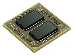 VIA's QuadCore X4 chip package
VIA has put out a little more data about the QuadCore X4 than it did for the Nano X2 that it is based on (yup, that is odd). The company says that it will run the four the four cores on the X4 package at 1.2GHz and higher, that all four 1MB L2 caches will be fired up, that the V4 bus will run at the top-end 1.33GHz speed, and that the TDP for the X4 package will be 27.5 watts.
VIA says that the X4 chip package is "21 per cent more energy efficient than the nearest competitor," but declines to say who that competitor is or what chip it is referring to.
VIA will be showing off the QuadCore X4 chip package at the Computex trade show in its stomping grounds in Taipei, Taiwan, at the end of May. It says it expects to begin volume shipments in the third quarter. ®
practical review on nano robo
Geophysical nano ROBO
Nanorobo to explore underground formations could squeeze through tiny cracks in the ground and report their finding to surface computers via radio. The nanorobo would contain sensors and on-board laboratories capable of analyzing their findings. These nanorobo would provide superior geophysical analysis compared to current subsurface analysis techniques.
The nanorobo
represent a system and method for exploring geophysical formations at
great depths below the surface of the earth.
In order to
explore the formation, nanorobo with a size less than 500 nanometers
are inserted into the formation. The nanorobo propel through the
formation, analyzing fluids and conditions as each moves through the
formation. The nanorobo can communicate with a machine on the surface
via a series of receivers and transmitters located in the wellbore.
A machine on
the surface is able to combine and analyze the data from the nanorobo
to create a three dimensional map of the formation. The map shows the
locations of pathways through the formation, pockets of hydrocarbons
within the formation, and the boundaries of the formation.
The
overriding problem in exploring for hydrocarbons in the subsurface is
the probing in, and characterizing of, an environment that cannot be
seen. Similarly once a commercial hydrocarbon deposit has been
discovered and is about to be developed and exploited much conjecture
and many assumptions must be made by reservoir geologists and reservoir
engineers in the modeling of a large volume of rock which cannot be
seen.
Subsurface
reservoir data is currently acquired from probes lowered into boreholes
and from images (seismography). In the first instance, the data is
handicapped by its insufficiency, by virtue of being sourced from a
single 6-inch hole, thus giving too narrow of a view. The interpreted
seismic volumes, on the other hand, gives too broad of a view due to
their imaging quality and resolution inadequacies. Even combining the
two, does not enable for the mapping of exact high permeability
pathways.
is a partial sectional view of a geophysical nanorobot based geophysical exploration system

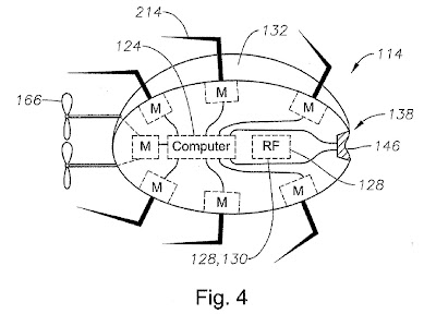
is a sectional view of a geophysical
nanorobo having multiple propulsion devices, a processor, a radio
frequency transmitter, and a sensor
is a partial sectional view of a geophysical nanorobo having a nano-processor control system
is a flowchart of operational propulsion of a plurality of geophysical nanorobo in a geophysical formation

X . IIIIII
nano circuits

This is really an awesome article. Thank you for sharing this.It is worth reading for everyone.
BalasHapusVibrator Spare Parts
geophysical equipments