X . I
electronic transmission components discipline


Transmission line loudspeaker
A transmission line loudspeaker is a loudspeaker enclosure design (topology) that uses an acoustic transmission line within the cabinet, compared to the simpler enclosures used by sealed (closed) or ported (bass reflex) designs. Instead of reverberating in a fairly simple damped enclosure, sound from the back of the bass speaker is directed into a long (generally folded) damped pathway within the speaker enclosure, which allows far greater control and use of speaker energy, and the resulting sound.
Inside a transmission line (TL) loudspeaker, is a (usually folded) pathway into which the sound is directed. The pathway is often covered with varying types and depths of absorbent material, and it may vary in size or taper, and may be open or closed at its far end. Used correctly, such a design ensures that undesired resonances and energies, which would otherwise cause undesirable auditory effects, are instead selectively absorbed or reduced ("damped") due to the effects of the duct, or alternatively only emerge from the open end in phase with the sound radiated from the front of the driver, enhancing the output level ("sensitivity") at low frequencies. The transmission line acts as an acoustic waveguide, and the padding both reduces reflection and resonance, and also slows the speed of sound within the cabinet to allow for better tuning.
Transmission line loudspeakers designs are more complex to implement, making mass production difficult, but their advantages have led to acclaim for a number of manufacturers such as IMF, TDL, PMC, KVART & BØLGE and the like. As a rule, transmission line speakers tend to have exceptionally high fidelity low frequency response far below that of a typical speaker or subwoofer, reaching into the infrasonic range (British company TDL's studio monitor range from the 1990s quoted their frequency responses as starting from as low as 17 Hz depending upon model with a sensitivity of 87 dB for 1 W @ 1 metre), without the need for a separate enclosure or driver. Acoustically, TL speakers roll off more slowly (less steeply) at low frequencies, and they are thought to provide better driver control than standard reflex cabinet designs, are less sensitive to positioning, and tend to create a very spacious soundstage. Modern TL speakers were described in a 2000 review as "match[ing] reflex cabinet designs in every respect, but with an extra octave of bass, lower LF distortion and a frequency balance which is more independent of listening level".
Although more complex to design and tune, and not as easy to analyze and calculate as other designs, the transmission line design is valued by several smaller manufacturers, as it avoids many of the major disadvantages of other loudspeaker designs. In particular, the basic parameters and equations describing sealed and reflex designs are fairly well understood, the range of options involved in a transmission line design mean that the general design can be somewhat calculated but final transmission line tuning requires considerable attention and is less easy to automate.
Purpose and design overview
Low frequencies, which remain in phase, emerge from the vent which
essentially acts as a second driver. The advantage of this approach is
that the air pressure loading the main driver is maintained which
controls the driver over a wide frequency range and reduces distortion.
[The TL design] also produces higher SPL [sensitivity or loudness] and lower bass extension than ported or sealed box of similar size.
I have an intuitive abhorrence of resonance enhancement to give a
loudspeaker more "kick" or apparent bass as they can sound
"single-noted". Yes you can pick out the bass rhythm but what about the
melody. What a transmission line gives in my experience is a much
smoother and more realistic bass quality.
- "I believe that speakers should preserve the integrity of the signal waveform and the Audio Perfectionist Journal has presented a great deal of information about the importance of time domain performance in loudspeakers. I’m not the only one who appreciates time- and phase-accurate speakers but I have been virtually the only advocate to speak out in print in recent years. There’s a reason for that.
- It is difficult and costly to design and manufacture a time- and phase-accurate speaker system. Few of today’s high-end loudspeakers are time- and phase-accurate designs. The audio magazines need to appeal to a broad spectrum of advertisers including many who make speaker systems which are time incoherent. The magazines, and the reviewers who write for them, have ignored or downplayed the issue of time- and phase-accuracy in order to maximize advertising revenue. I am not alone in recognizing this situation."
Essentially, the goal of the transmission line is to minimize acoustical or mechanical impedance at frequencies corresponding to the driver's fundamental free air resonance. This simultaneously reduces stored energy in the driver's motion, reduces distortion, and critically damps the driver by maximizing acoustic output (maximal acoustical loading or coupling) at the terminus. This also minimizes the negative effects of acoustic energy that would otherwise (as with a sealed enclosure) be reflected back to the driver in a sealed cavity.
Transmission line loudspeakers employ this tube-like resonant cavity, with the length set between 1/6 and 1/2 the wavelength of the fundamental resonant frequency of the loudspeaker driver being used. The cross-sectional area of the tube is typically comparable to the cross-sectional area of the driver's radiating surface area. This cross section is typically tapered down to approximately 1/4 of the starting area at the terminus or open end of the line. While not all lines use a taper, the standard classical transmission line employs a taper from 1/3 to 1/4 area (ratio of terminus area to starting area directly behind driver). This taper serves to dampen the buildup of standing waves within the line, which can create sharp nulls in response at the terminus output at even multiples of the driver's Fs.
In a transmission line speaker, the transmission line itself can be open ("vented") or closed at the far end. Closed designs typically have negligible acoustic output from the enclosure except from the driver, while open ended designs exploit the low-pass filter effect of the line, and the resultant low bass energy emerges to reinforce the output from the driver at low frequencies. Well designed transmission line enclosures have smooth impedance curves, possibly from a lack of frequency-specific resonances, but can also have low efficiency if poorly designed.
One key advantage of transmission lines is their ability to conduct the back wave behind the transducer more effectively away from it – reducing the chance for reflected energy permeating back through the diaphragm out of phase with the primary signal. Not all transmission lines designs do this effectively. Most offset transmission line speakers place a reflective wall fairly close behind the transducer within the enclosure – posing a problem for internal reflections emanating back through the transducer diaphragm. Older descriptions explained the design in terms of "impedance mismatch", or pressure waves "reflected" back into the enclosure; these descriptions are now considered outdated and inaccurate as technically the transmission line works through selective production of standing waves and constructive and destructive interference (see below).
A second benefit is that the resulting music is time coherent (i.e., in phase). Fried quoted in 2002, a listening test performed and reported in December 2000's Hi-Fi News (as he believed) in which a high-quality recording was obtained using reputable but non-time-coherent loudspeakers and this recording was then time phase corrected; an expert listening panel "voted unanimously for the superior realism and accuracy of the time corrected output" for high quality sound reproduction.
A transmission line speaker employs essentially, two distinct forms of bass loading, which historically and confusingly have been amalgamated in the TL description. Separating the upper and lower bass analysis reveals why such designs have so many potential advantages over reflex and infinite baffle designs. The upper bass is completely absorbed by the line allowing a clean and neutral response. The lower bass is extended effortlessly and distortion is lowered by the line’s control over the drive unit’s excursion. One of the exclusive benefits of a TL design is its ability to produce very low frequencies even at low monitoring levels – TL speakers can routinely produce full range sound usually requiring a subwoofer, and do so to very high levels of accuracy. The main disadvantage of the design is that it is more labor-intensive to create and tune a high quality and consistent transmission line, compared to building a simple enclosure. A 2010 Hifi Avenue TL speaker review commented that "One thing I have noticed about transmission line designs is that they create a rather big soundstage and seem to handle crescendoes with ease".
History of transmission line loudspeakers
Invention and early use
This image is actually an inverted folded horn. You can tell as the
throat is larger than near the port opening. A true Transmission Line
enclosure is the same width 'vent' throughout. .
"Classic" era transmission line loudspeakers
- Source for much of this section: Loudspeakers: for music recording and reproduction (Newell & Holland, 2007)
Shortly thereafter the design entered mainstream Hi-Fi, through the works of Irving M. "Bud" Fried in the United States, and a British trio: John Hayes, John Wright, and David Brown. Dave D'Lugos describes the period that followed (approx. 35 years until the start of the 21st Century) as a period when the "classical designs" were created.
Fried was exposed during his time at Harvard University to high fidelity audio reproduction, and later became an importer of audiophile items. Under the trademark "IMF" (his initials), from 1961, he eventually became involved with many advancements in audiophile equipment: cartridges (IMF – London, IMF – Goldring), tone arms (SME, Gould, Audio and Design), amplifiers (Quad, Custom Series), loudspeakers (Lowther, Quad, Celestion, Bowers and Wilkins, Barker, etc.). In 1968 he met John Hayes and John Wright, who had already designed an award winning tone arm in the UK and had brought along a transmission line speaker designed by John Wright - described by Hayes as "fanatical regarding quality" - in order to promote and demonstrate the tone arm at a New York hifi show. Irving unexpectedly received a number of orders for the unnamed speaker, which he dubbed the "IMF". The British pair, along with Hayes' colleague David Brown, agreed to form a UK company to design and manufacture speakers which would be sold by Irving in the United States. John Hayes later wrote that:
- Of course, Bud, had called it the IMF, and therefore, perhaps mistakenly we registered IMF and formed an IMF company... At no time did Bud Fried have any input on the designs. We sold him speakers and he was the US Distributor... [...] Bud Fried was never a Director or shareholder of IMF Electronics. IMF electronics were the only company manufacturing the transmission line speakers. The name IMF was adopted because Bud Fried had demonstrated the first prototype speakers at the New York hi fi show, and because of the publicity and the fact that he had used his name on the then unnamed speakers, we stuck with the name which was a mistake on our part. It was never his company. After our lawsuit he called his speakers Fried.
21st century
In the early 21st century, mathematical models that seemed to approximate the behavior of real-world TL speakers and cabinets, began to emerge. According to the website t-linespeakers.org, this led to an understanding that what he termed the "classical" speakers, designed largely by "trial and error", were a "good job" and the best that was reasonably possible at those time, but that better designs were now achievable based on modeled responses.Design principles

Fig. 1 - Relationship between TL length and wavelength

Fig. 2 - Frequency response (magnitude) measurement of Drive unit & TL outputs
The complex loading of the bass drive unit demands specific Thiele-Small driver parameters to realise the full benefits of a TL design. Most drive units in the marketplace are developed for the more common reflex and infinite baffle designs and are usually not suitable for TL loading. High efficiency bass drivers with extended low frequency ability, are usually designed to be extremely light and flexible, having very compliant suspensions. Whilst performing well in a reflex design, these characteristics do not match the demands of a TL design. The drive unit is effectively coupled to a long column of air which has mass. This lowers the resonant frequency of the drive unit, negating the need for a highly compliant device. Furthermore, the column of air provides greater force on the driver itself than a driver opening onto a large volume of air (in simple terms it provides more resistance to the driver's attempt to move it), so to control the movement of air requires an extremely rigid cone, to avoid deformation and consequent distortion.
The introduction of the absorption materials reduces the velocity of sound through the line, as discovered by Bailey in his original work. L Bradbury published his extensive tests to determine this effect in an AES Journal in 1976 his results agreed that heavily damped lines could reduce the velocity of sound by as much as 50%, although 35% is typical in medium damped lines. Bradbury’s tests were carried out using fibrous materials, typically longhaired wool and glass fibre. These kinds of materials however produce highly variable effects that are not consistently repeatable for production purposes. They are also liable to produce inconsistencies due to movement, climatic factors and effects over time. High specification acoustic foams, developed by manufacturers such as PMC, with similar characteristics to longhaired wool, provide repeatable results for consistent production. The density of the polymer, the diameter of the pores and the sculptured profiling are all specified to provide the correct absorption for each speaker model. Quantity and position of the foam is critical to engineer a low pass acoustic filter that provides adequate attenuation of the upper bass frequencies, whilst allowing an unimpeded path for the low bass frequencies.
Mathematical equations, modelling, and design process
- The external links section of this article links to a number of resources that detail the mathematical principles, models, and DIY calculations, as well as extended practical design material, related to transmission line speakers.
- "The classic transmission line bass enclosure has never been completely and successfully modeled such that it can be built from a pat set of equations. Some claim to have done this, but it doesn't seem to allow a first time build without adjustments, so the models have enough wrong to require a fudge factor..."
However from the 21st century, Martin King and George Augspurger (both separately and referencing each other's works), produced models which show these to be "generally less than optimal" designs which "did a good job of approaching what was possible in their day". Audio engineer Augspurger had modeled TL using an electrical analogy, and found it to agree closely with King's existing work, based on a mechanical analogy. D'Lugos concluded in his overview of TL modeling and design theory: "I think that using modern drivers & tools such as King's software you can build a better TL easier today".
Prominent individuals and companies
Pioneers:-
- Benjamin Olney - originated the idea of a duct in speaker enclosure design, which he termed an "acoustic labyrinth", while working for Stromberg-Carlson as an acoustic engineer and studying the effect of enclosure size on output sound.
- Bailey and Radford - worked together and developed the concept for loudspeakers (1965). Their design was a significant development from the earlier work. Bailey's name was on the article and Radford built the first commercial TL speaker.
- John Wright together with business partner John Hayes and (later) David Brown, and their company IMF Electronics Ltd (later: TDL) - Wright, a "fanatical" pursuer of quality, had designed an award winning tone arm and to demonstrate it, brought to New York a non-commercial TL speaker he had also designed. The speaker gained considerable attention and Wright, Hayes and colleage Brown formed a company that specialized in TL speakers, and won numerous awards (1968). TDL disbanded following Wright's death in 1999 and the brand - as a shell - was bought by Richer Sounds.
- Irving M. "Bud" Fried - American audiophile and TL advocate, who encountered Wright and Hayes in 1968, recognized the potential of Wright's unnamed speaker, and began marketing their TL speakers in the United States. Later set up a TL company of his own to design speakers.
- Martin King and George Augspurger - researchers and designers who succeeded in modeling realistic TL speaker designs in the early 21st century.


X . II
Otomotif Transmission
automatic transmission ismeaning automatic transmission is, the notion of automatic transmission
Here is a brief definition of the word automatic transmission in automotive or motor engine.Automatic Transmission: Automatic transmission Meaning. Transmission or gearbox or automatic gear shift. If the car or the usual conventional transmission, the clutch works by shifting gears and then back on the gas. This automatic transmission then do not use the clutch. The driver only needs to step on the gas (such as when riding a boom-boom car). In a certain speed gear will switch itself off and the vehicle will keep going faster in accordance with the driver's gas pedal.This transmission system is suitable for Urban Vehicle or car in a city full of traffic jams. Because the driver will obviously not be exhausted because of holding the clutch. Some cars use this type of transmission, for example, Hyundai Atoz or Mercedes Benz A-Class. But many drivers prefer a manual transmission because of the 'pull' strength is more pronounced.
Automatic Transmission
This means that the automatic transmission. Transmission or gearbox or automatic gear shift. If the car or the usual conventional transmission, the clutch works by shifting gears and then back on the gas. This automatic transmission then do not use the clutch. The driver only needs to step on the gas (such as when riding a boom-boom car). In a certain speed gear will switch itself off and the vehicle will keep going faster conformed to the gas pedal of the driver. This transmission system is suitable for Urban Vehicle or car in a city full of traffic jams. Because the driver will obviously not be exhausted because of holding the clutch. Some cars use this type of transmission, for example, Hyundai Atoz or Mercedes Benz A-Class. But many drivers prefer a manual transmission because of the 'pull' strength is more pronounced
Automatic 4WDThis system moves with 2WD, until the system detects the need to use 4WD. Automatically power is divided into front and rear wheels in accordance with the ratio of field conditions. In general, the automatic system works when one of the tires slip. More modern, using software that can turn into a 4WD before wheel slip, by analyzing road conditions.

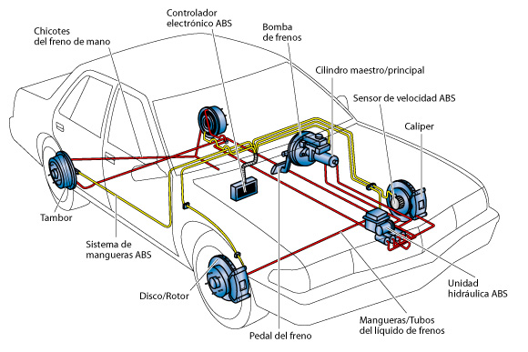
Anti-lock Braking System is useful to prevent locking effect on the brake pedal when the car suddenly so avoid the possibility of slippage due to the effects of pushing force vehicles away from the center point (centrifuges). The trick is to sensors that provide input or control, when to stop and when the wheels must spin the wheel. So when vehicle brakes, the wheels are not locked and the driver remains in control of the vehicle. This technology was first introduced by Daimler when it was still just a duet with Benz in 1970. ABS originally given the name of anti-block system created by Hans Scherenberg diStuttgart, Germany.
transmission
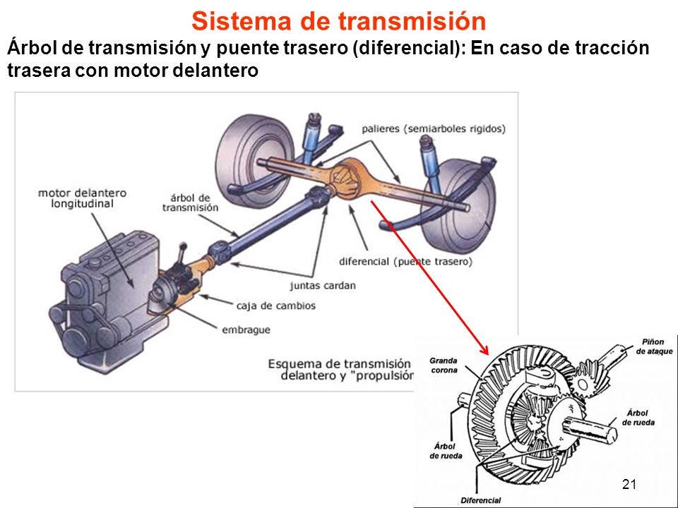
The transmission system
Speed shift lever (5 speed) at the Mazda Protege.Transmission system, in automotive, is a system that works for the conversion of torque and speed (revolutions) of the engine torque and speed be different to be forwarded to the final drives. This conversion changed the high rotational speed becomes lower but more powerful, or vice versa.Example 5-speed transmission at 4,400 engine rpmGir gir RPM ratio numbers onexit shaft transmission1 3,769 1,1672 2.049 2.1473 1.457 3.0204 1,000 4,4005 0.838 5.251The highest torque of an engine generally occurs around the middle of the permitted engine speed limit, while vehicles requiring the highest torque at the time began to move. In addition, vehicles running on roads that climb requires higher torque than a car that runs on a flat road. Vehicles that run at low speed requires higher torque than high speed. With the operating conditions vary, so it needed power transmission system so that needs can be met by the machine.
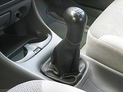
The manual transmission
Top and side view of a manual transmission that is placed on the floor of Ford with 4 speeds
The manual transmission is the type of transmission used in motor vehicles. This system uses a clutch operated by the driver to arrange the transfer of torque from the engine to the transmission, as well as the gear shift operated by hand (in the car) or legs (the motor). Gear acceleration assembled in the gear box / Reducer for some speed, typically ranging from 3 to 6 forward gear acceleration combined with one reverse gear (R). Gear acceleration is used depends on the speed of the vehicle at low speeds or uphill used gear acceleration 1 and so that the higher the speed, and vice versa if decelerate unloaded gear acceleration, braking can be assisted with a reduction gear acceleration.
Top and side view of a manual transmission that is placed on the floor of Ford with 4 speeds
synchromesh
Is a synchromesh transmission equipment which serves to equalize the rotation between the teeth to be connected so that the acceleration gear shifting can be done seamlessly. How it works when the transmission lever in neutral position, the synchromesh is in the middle does not affect or be affected by both the gear by his side.
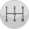
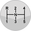
Composition of gear acceleration
5-speed transmission lever in the Mazda Protege.
The arrangement / layout gear manual gearbox depending on the characteristics of commonly used sector in the region, Asia is somewhat different car output with Europe, especially in the placement of reverse gear (R). Placements are widely used transmission lever is on the floor but some modern cars use the transmission lever on the dashboard or old cars placed on the handlebars steering wheel.
 5-speed transmission lever in the Mazda Protege.
 Transmission lever floor
pattern explanation
manual Layout.svg
It is a 5-speed gear arrangement commonly used in modern cars plus one reverse gear marked with R. Placement reverse gear (R) is crucial because it can enter an interference with the vehicle, because if the teeth 5 wrong move could prove fatal to retreat ,
manual Dogleg.svg
This arrangement is an arrangement of five-speed gear commonly used in lightweight bus plus one reverse gear marked with R. Dental 1 is rarely used, is used when climbing on steep climbs.
the gear lever on the steering wheel
The gear lever on the steering Saab96
pattern explanation
Manual Layout Layout 3.svg car with three forward gears which is an arrangement of gear acceleration output American cars of the 1930s until the 1950s that at the time dubbed "three on the three"
Column4MT.svg is a layout that was developed after that, which was also developed by the output of cars of Europe and Japan. Until it is still used in some commercial cars such as the Mitsubishi L 300.

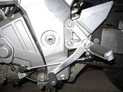
Motorcycle gear lever
Suzuki SV650S acceleration gear lever.
Corak exchange motorcycle gear acceleration that are commonly used:
6
5 ┘
4 ┘
3 ┘
2 ┘
N
1
Acceleration gear lever with his left foot stepped on to get into first gear and prying upwards to get into gear 2, 3, and so on. If you want to lower the speed, the acceleration gear lever stepped down from 5 to 4 to 3 and so on.
Advantages and BenefitsFuel consumption
The manual transmission (M / T) connecting the engine to the transmission with clutch-rigid compared with a torque converter in the automatic transmission (A / T) or v-belt in the continuously variable transmission (CVT). The manual transmission also does not waste energy because there is no hydraulic pump as the transmission of A / T. Therefore, the car with the transmission M / T is generally more efficient than the A / T or CVT; even so the difference in fuel consumption has been somewhat reduced due to the emergence of locking torque converter on the transmission of A / T. The difference in fuel consumption between the M / T and A / T approximation 5-15% depending on the way of driving and road conditions. Next, the transmission M / T also does not require active cooling and for mechanical simpler than A / T, then the weight is lighter than the car with the transmission of A / T. Durability and maintenance feeendurance
Transmission M / T has a simpler mechanical system with parts less than A / T. Therefore, the treatment was generally easier and cheaper. In addition, the transmission M / T does not have any electrical components, pumps, and cooling mechanisms such as the transmission of A / T.The cost of care
The cost of vehicle maintenance manual are generally cheaper than the automatic. The new price of the vehicle manual also cheaper than the automatic.lubrication
Most transmission M / T depending on the splash lubrication despite some gearbox Rover also has an oil pump.Performance and Control
Transmission M / T is generally a greater number of gear ratios (gear ratio). Most vehicles have 5 to 6 speed manual gear, while transmitting A / T is usually only four teeth. Number of teeth which will further streamline the more fuel consumption.Braking engine (Engine Brake)Transmission A / T does not have an effective engine braking. This means that the machine is not effectively slows the car when the driver took off control speed. This causes the driver will use a lot of brakes, so the brake on the car A / T will wear faster.

automatic transmission
Pieces automatic transmission
Dental automatic planetary transmission.
The automatic transmission is the transmission to shift gears automatically accelerated. To change the rate of speed in the automatic transmission system is used the mechanism of friction and automatic transmission oil pressure. In the automatic transmission planetary gear serves to change the rate of speed and torque as well as on the gear manual transmission.
The tendency of people to use the automatic transmission has increased in recent years, particularly for luxury cars, and even certain types are already fully automatic transmission. the trend same was true on a motorcycle like Yamaha Mio, Honda Vario.
 Pieces automatic transmission
 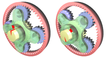 Dental automatic planetary transmission.
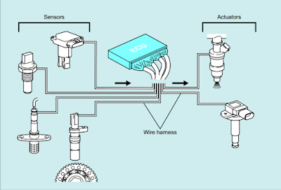
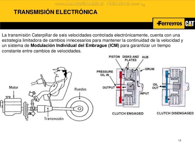
Mode automatic transmissionTransmission DCT (Dual Clutch Transmission) Honda
The automatic transmission is controlled by simply moving the lever acceleration to a particular position. The position of the automatic transmission lever are sorted by the format of the P-R-N-D-3-2-L, as there are from left to right or from top to bottom. Machines can only be switched on in the position P or N only.
Generally, the automatic transmission mode is as follows:
P (Park) is a position for parking the vehicle, Transmission locked in this position so that the vehicle can not be driven.
R (Reverse) is a position to reverse the vehicle.
N (Neutral) is a neutral gear position, engine relationship with the wheels in the free state.
D (Drive) is a position to go forward under normal conditions.
2 / S (Second) is a position to move forward on mountainous terrain.
1 / L (Low) is an advanced position on the gear shift to one, only used when driving on extremely steep terrain.
While optional is:
3 is a position to go forward and the transmission will not switch on the top gear position.
O / D (Over Drive) is the position of the transmission gear so that the displacement occurs at higher engine speed.
Varian AT
4A / T is the transmission variant A / T that is often encountered in many mobil.Teknologi 4A / T is long enough to be present at Indonesia.Digunakan car era 70's until now. Cars that use this system include: Toyota Kijang LGX Krista 4AT and 4AT, Honda CR-V, Honda Fit / Honda Jazz, Toyota Crown, Toyota Camry, Toyota Corolla Altis, Toyota Corona, Honda Civic, dsb.4A / T using the format PRNDS / 2-L / 1 (without transmission D3 / 3 and without O / D).
5A / T. Not much different from the transmission 4A / T, only format that different.If format 4A / T is PRNDS / 2-L / 1, the 5A / T has PRND-format D3 (or) O / D-2-1.5A / T is used the car of the year 1990'an until now (rare car using 5A / T before the era of 90s they still wear 4A / T), among others: Suzuki Grand Vitara, Honda Brio, Honda Freed, Honda Fit / Honda Jazz, etc.
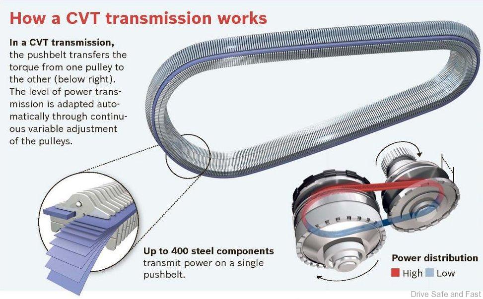
CVT automatic transmission on a motorcycle matic
CVT is the power transmission system from the engine to the rear tire using a belt connecting the drive pulley to the driven pulley. Automatic transmission is generally used in a scooter-type motorcycle (scooter), although it is starting to be applied also to the cub-type motorcycle. Automatic transmission is an automatic transmission used "V" Belt, known as the CVT (Continuous Variable Transmission). CVT no longer use the gears to set a transmission ratio, but uses a belt (V-Belt) and Vully to obtain variable gear ratio that varies.
construction CVT
The basic construction CVT pulleys based variable that the mechanical work consists of three main components:
Belts (V Belt) of rubber material
Primary pulley (drive pulley)
Secondary pulley (driven pulley)
Construction CVT pulley consists of fruit two variable positioned at a certain distance and both are connected by a belt (V Belt). Each pulley consists of two parts cone-shaped rear section attached to each other. Pulleys used in so-called CVT pulleys variable , where one of the pulleys can be moved closer or away from the other parts of the pulleys. This is due to both components of the pulleys are centrifugal with a spring mechanism that regulates the shift inverting each piece pulley continuously by the high and low spin machine. A V-shaped belt made of rubber material installed in the center pulleys to connect the two pulleys. Belt inner side is made of jagged, with the aim to improve the ability of the contact (grip) on the belt pulleys.
Primary pulley (drive pulley) to direct connected with a motorcycle engine and driven pulley (secondary pulley) is connected to the rear wheel via the intermediary drive mechanism in the form of centrifugal clutch and a reduction gear. Belts are used to connect the power play from the drive pulley to the driven pulley.How CVT works
When Round Stationary Engines
In the stationary rotation, centrifugal force that occurs in a string of shoe centrifugal clutch unit has not been able to beat the centrifugal spring tension. Shoes are not able to play the home friction clutch, so that the centrifugal clutch is not working. Engine torque which has been forwarded by stopping transmission on centrifugal clutch unit so as to wheel and motorcycles are not running.
When Round Raised Engineering / Motorcycles On the Road
When the engine rotation increases of approximately 3000 rpm, centrifugal force that occurs in the friction shoe is already quite large. Friction shoe will be thrown out and the house scraped clutch. In these vehicles centrifugal clutch begin forwarding to wheel rear engine torque so that the motorcycle starts. while the centrifugal force received a ballast roller on the drive pulley is not sufficient to overcome the spring tension on the driven pulley. This causes the driven pulley tightens (the output is a large diameter). Because the length of the belt fixed, then the drive pulley will adjust to be in a position to widen, (small diameter). Large transmission ratio so as to produce a comparison round lightweight and large torque.
When High Speed Machine
At the time of the engine rev up to medium speed, centrifugal force received a ballast roller on the drive pulley is large enough, so that the roller was thrown out, pressing pulley sliding on the drive pulley to move towards narrowing and drive belt drive pulley diameter gets larger. The length of the belt so that the belt stays on the driven pulley to a position that is wider (smaller diameter). This situation makes the transmission ratio decreases so that the rate increases the speed of the motorcycle.
When Round-Speed Machine
If the machine reaches high speed, the centrifugal force received a ballast roller on the drive pulley semangkin powerful that the outer roller thrown kesisi, strong semangkin pressing pulley sliding on the drive pulley to move towards narrowing and drive belt to the drive pulley diameter greatest. Pull the belt on the driven pulley will be even greater, pressing the driven pulley spring to shift the drive pulley to the widest position (smallest diameter). This situation makes the transmission ratio is getting smaller so that the rate is the higher the speed of the motorcycle.
When Motorcycles Carrying Heavy Load, accelerating or Streets Uphill
At the time of a motorcycle carrying a heavy load, or accelerate quickly when walking uphill, it takes a large torque so that the motorcycle can keep going. Conditions often encountered in this situation is the motorcycle was driving at low speeds, but this time it takes a large torque. Usually the driver will try to increase the torque produced by the engine by opening the valve wide open so that the engine turns up and produces great torque. In the CVT that works automatically by setting the engine rotation, this will be an obstacle. Normally, when the engine rotation is increased, then the transmission ratio will decline so this would be troublesome because the torque produced would be reduced. Therefore, to overcome this difficulty, the CVT is equipped with a device called a kick down mechanisme. Construction of the kick down mechanism located on the driven pulley, consisting of grooves made on a sliding pulli and nok / cam torque invested in fixed pulleys. At the time of the rear wheel gain custody street .
Semi-automatic transmission
Ferrari F430 steering wheel incorporates acceleration gear shifting
Semi-automatic transmission is a transmission that acceleration without touching the gearshift / depress the clutch, the system uses electronic sensors, processors and actuators to move the gear acceleration on the orders of the driver. This system was developed to anticipate traffic congestion in urban areas. Semi-automatic transmission is also used in luxury sports cars such as used Porsche, Maserati, Ferrari is sometimes placed on the steering wheel to ease the switch gear acceleration.other applications
Motorcycle circulating in Indonesia in the early 1970s up to now generally use semi-automatic transmission that is simple, moped very popular at that time have only recently started to be produced and marketed motorcycle automatic transmission as used on Yamaha Mio, Honda Vario.Trade name semi automatic transmission
 Ferrari F430 steering wheel incorporates acceleration gear shifting
 Quickshift - Renault
2-tronic - Peugeot
Allshift, Twin Clutch SST - Mitsubishi
C-Matic - Citroën (Citroën CX and Citroën GS)
Easytronic - Opel
Durashift EST - Ford
Dualogic - Fiat
MultiMode, SMT (Semi Manual Transmission) - Toyota
I-SHIFT - Honda
Senso Drive or EGS or BMP - Citroën
Speed Gear - Fiat
Selespeed - Alfa Romeo, Fiat
Softouch - Smart
Sportronic - Mitsubishi
Duo Select - Maserati
Automatic Stickshift - Volkswagen
Sequentronic - Mercedes-Benz
SMG / SSG - BMW
S-Tronic - Audi
DSG (Direct Shift Gearbox) - Seat, Škoda, Volkswagen
DCT - Volkswagen, Bugatti, Koenigsegg
PDK (Porsche Doppelkupplungen) - Porsche
AMT (Automated Manual Transmission) - Proton
Main component
Clutch (clutch) or torque converter. Clutch is used for manual and semi-automatic transmissions and automatic transmission, the torque converter is used in the automatic transmission.
Transmission, also known as the gears.
Clutch / Torque converter
The clutch is a device used to connect two shafts at both ends for the purpose of transmitting mechanical power. Clutch normally does not allow the separation between the two shaft when operating, but at this time there is a clutch torque that is limited so that it can slip or disconnect when the torque limit is passed.
Coupling two rotating shafts
The main purpose of the clutch is to unite the two parts which can rotate. With the selection, installation, and maintenance is meticulous, clutch performance to the maximum, minimum power loss can be, and maintenance costs can be reduced.
 Coupling two rotating shafts
 benefit
Clutch used in machinery for various purposes:
To connect two units shaft made separately, such as the motor shaft with a wheel or shaft generator to the engine. The clutch is able to separate and connect the two shafts to the needs of repair and replacement of components.
To obtain mechanical flexibility, especially on the two shafts that are not on one axis.
To reduce shock loads (shock load) from one shaft to another shaft.
To avoid excessive workload.
To reduce the vibration characteristics of the two rotating shafts.
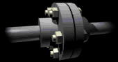
Clutch typeRigid couplings
Rigid coupling is a coupling unit that brings together two types of shafts which does not allow a change in position of the second shaft or released, intentionally or unintentionally, when in operation. Rigid coupling is the right choice when second shaft want to be associated with the setting position is stable and precision. This clutch is a clutch with the highest service life for limitation of torque, RPM, and the weight of the shaft and the clutch is not exceeded .flexible couplingBeam couplings with threaded part helix Rzeppa joint and ...... Double Cardan Joint which is an example of a clutch CV
 Coupling beam with its helical threaded part
Clutch gearOldham couplingsuniversal joint
Flexible coupling is used when there is little change in the second shaft axially position, radial, and angular when the engine is operating. Some types of flexible couplings, namely:
Beam
Clutch CV (constant-velocity)
diaphragm
disc coupling
Fluid coupling
Clutch gear (gear coupling)
Hirth joint
Oldham
Rag joint
universal joint
Coupling beam, or it could be called a helical coupling, is delivering power coupling between the two shafts to allow the change of position of the shaft in angular, axial and parallel to a limited extent, when the shaft work. The design of the coupling beam is a clutch that has an empty section along the body of helical or spiral-shaped coupling, thus making it flexible. Coupling beam is usually made of aluminum alloy, stainless steel, and titanium.
Gear coupling is a clutch that transmits power between two shafts which are not in one line. The second shaft is connected to the third shaft in the clutch so-called spindle.
CV clutch is a clutch that allows for transmitting power at varying angles and at a constant rotational speed. Clutches of this type commonly used in automobile front wheel drive and all-wheel drive.
Universal joint is the type of coupling in the form of two rigid bars that allow the deflection of the direction of power transmission from the power source. Uniersal hinge joint consists of a pair of adjacent and connected to the cross shaft. Universal joint, though it transmits power which is not in line, but has a drawback, which can provide output RPM is not constant despite constant RPM input. It can cause vibration and wear on engine components.
 Rzeppa joint and ...
 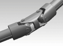 , Double Cardan Joint which is an example of a clutch CV
  Clutch gear
  Oldham couplings
  Universal joint
Gearboxes / transmision
Bristol 171 Sycamore helicopter gears
Gear is the gear and hydraulic system that delivers mechanical power from the drive to the wheels with lower speed but higher turning force. This system also allows the change of speed-power ratio or the direction of rotation.
In the car, known as manual and automatic transmission. Manual means the rider to change gears with the help of the stalk. This system is cheaper, lighter, typically have better performance, and consume less fuel. Automatic transmission easier to use and are usually found in the car of US products. There was also a semi-automatic gearbox system, ie when replacement gear shaft is driven by a computer.
 Bristol 171 Sycamore helicopter gears


X . III
building transmission


X . IIII
transmission on a bike / bicycles


Automatic Bicycle

The “Nuts and Bolts” of Automatic Bicycles
Automatic bikes are complex machines. The front hub of the bicycle is fitted with a gauge to determine wheel revolution. This information is sent to a computer chip housed near the pedals.Throughout each bicycle ride, the sensors constantly search for the desired gear, or the gear which will allow the rider to maintain his or her preferred cadence.
Some bicycles with automatic transmission allow the rider to choose a preferred cadence by pressing up and down buttons. When a desired cadence has been chosen, the computer chip will constantly and automatically shift the bike’s gears to stay in that cadence, taking out all of the guesswork on the rider’s part.
Why Make an Automatic Bicycle?
Industry leaders who worked to develop the automatic transmission felt the biking industry fell into a slump after the 1980’s and 90’s when mountain biking and road racing became very popular.Did you know...?

Shimano, a leading bicycle manufacturer, unveiled a bicycle that could be controlled using an iPhone app. The app detects the rider's cadence using sophisticated wheel sensors and adjusts the gears accordingly by streaming data from the iPhone to the transmission system using Bluetooth technology.
Surveys conducted by Shimano, one of the leading experts in the automatic bicycle industry, showed Americans felt bicycling was becoming too elitist.
Many non-expert bikers felt the sport was too difficult and complex to even attempt, and many riders didn't want to ride for fitness or competition, they just wanted to ride for fun.
This desire led to the bicycle with automatic transmission, so all of the complication and guesswork was taken out of biking, allowing the rider to take up biking again in a carefree, fun way.
Is the Automatic Bicycle For You?
Bicycle automatic shifting is not intended for everyone, nor is intended for all biking situations. They are not high-performance vehicles for road racing and for mountain biking. They shouldn't even be used in inclement weather.If you loved biking as a kid, and you are interested in taking up biking again just for fun, bicycle with automatic transmission may be just the thing for you. This is also the case if you want to bike simply for the joy of cycling, and you're not interested in racing, competition or any type of extreme biking.
A bicycle with automatic transmission is a simple, fun way, to reenter the world of cycling if you have been away, or a great bike for leisure rides with the family or friends when you want a break from more competitive, hard-core cycling.
When I first learned to drive, I learned on a car with a manual transmission. It never seemed especially difficult because that was what I got used to. In fact, the first time I had to drive an automatic, I remember being very confused. What was I supposed to do with my left foot? Do I not have to shift at all? And if it’s automatic, then what’s with all these different choices on the gearshift lever? I quickly got the idea, of course, but still preferred the increased control and responsiveness I got from making my own decisions about when to shift. It would therefore seem that I should have the same attitude about bicycles, which not only require manual shifting but typically have many more than four or five gears. But manual bicycle transmissions have always given me trouble, and I’ve frequently wished I could have the convenience of an automatic transmission on a multi-speed bike.
Gearing Up for a Change
Sure enough, automatic bicycle transmissions have been in development for almost 30 years, though only recently have they become commercially available. Mechanically, the main thing needed for an automatic bike transmission is a motor or piston that moves the chain between gears in place of the standard lever-operated cable. This is a relatively straightforward engineering problem, but the difficult thing is working out how and when to tell the gears to shift. That computation currently requires the use of a tiny, battery-operated computer along with sensors that determine the current gear and the speeds at which wheels, pedals, and sprockets are moving. The computer constantly recalculates the optimal combination of front and rear gears to keep the rider at a consistent pedaling cadence, automatically signaling the gears to shift lower when going uphill or higher when going downhill. Using a controller on the handlebars, riders can, if they wish, adjust the gearing to provide a more intense workout or a gentler ride; they can also override the automatic shifting entirely and use it as a power-assisted manual transmission.
The first automatic bicycle transmission was designed by the Browning family, whose main claim to fame had been gun design. Now an independent company based near Seattle, Browning Components, Inc. focuses solely on bicycles and bike transmissions. Their most interesting innovation is a special gear with a hinged section (somewhat like a pizza slice) that swings in and out to guide the chain from one gear to the next. What’s great about the Browning mechanism is that the chain remains engaged in sprockets at all times, rather than simply dropping onto the next gear. This virtually eliminates the possibility of the chain slipping, and also makes it possible to shift smoothly and almost silently regardless of speed or load. Browning manufactures their own bikes (whose frames must be custom designed to accept the special transmission) and also supplies the transmission mechanism to other bike manufacturers.
Shifting More Than Gears
Shimano, the largest manufacturer of bicycle components such as brakes and shifters, has also begun selling automatic transmissions. One design uses a seven-speed, internally geared hub; another, which is not yet available in North America, uses a power-assisted derailleur system, but adds an automatic, powered suspension to adjust the comfort of the ride to fit current conditions. Bikes with the Shimano mechanism are significantly heavier and more expensive than their manual counterparts and are designed more for leisure riding than racing or mountain biking. The Browning mechanism, on the other hand, was first employed on bikes used for BMX racing, and adds somewhat less to the cost and weight of a bike.
Adding an automatic transmission to a bicycle seems—in the abstract at least—like a wonderful step forward in user interface. It replaces something awkward with something invisible, which is the way good technology should be. Whether or not the reality lives up to the hype (or will in the future), I don’t know. And something tells me it ought to be possible to create a purely mechanical automatic bike transmission. I’m not sure what happens to an electronic one when the batteries inevitably die; presumably it just stays in whatever gear it was last set to.
At this point, automatic bike transmissions are not taken very seriously among cycling enthusiasts. Some are put off by the extra weight; some feel it’s not worth the money just to avoid having to move a lever; and some just think automatic transmissions are for wimps.
FLASH BACK KNOW HOW THE BICYCLE ?

Bike. Transport equipment and exercise is still being conserved until now. The technology continues to evolve. From that time are still modest, has now become more complicated, and into many types, according to the needs of the wearer. Even so, the system remains essentially the same. Anyway, the bike is moving stick with stroke. How does the system work bike, consider the following.
Simply put, the power stroke of the foot moves forward gear. Front gear connected to the rear gear with the chain. Because interconnected, front gear when rotated the rear gear will also rotate and rotate the rear wheels.
If you notice, there is a bike that feels heavy or light when pedaled. Bike and rider weight affect this. But not only that. Another factor affecting among other things the number of gear ratio between front and rear gear, wheel size, the width of the tire tread, and the friction between moving parts.
Simply put, if the friction and weight of the bike is equated, it will get the following conclusions:- The weight of the bike pedaling the higher speed can be achieved. (Front gear ratios - the back is big enough)- The mild stroke bike, the lower the speed that can be achieved. (Front gear ratios - the back is quite small)
This conclusion is not absolute, because it depends on the strength of the stroke and the habits of each cyclist.
Factors heavy strokes:
The weight of the heavy bike
Fairly large front gear (number of teeth a lot)
The rear gear is quite small (number of teeth a little)
Large diameter rear wheels
Tire tread width
Friction large components
The sitting position is too low
Factors stroke feels light:
The weight of the bike light
Front gear small enough
The rear gear large enough
Small diameter rear wheel
Narrow tire tread
Minimal friction components
Optimal sitting position
The weight of the bike depends on the type of bike. Bicycles for competition is made possible se-light with enough force, in order to go fast. The bikes that we used to wear, made to be strong and durable at an affordable price, so it is relatively heavier.
Gear ratio has been no problem for the modern bicycle. Because it is equipped with a multi-speed gear shift, which we can use as needed. For bikes with a single gear, the gear can be removed and replaced with a size deemed more fitting.
The wheel also depends on the type of bike. Bike racing has a large diameter in order to go fast. MTB wheel size is slightly smaller. Type folding bike small diameter so quick. Usually the wheel size can not be replaced with different sizes, because it is limited to the size of the bike frame.
No tire tread width and there were narrow. Tires with good tread width for use in off-road terrain, because the force is large enough friction . However, when used on the road might be a bit heavy. Tires with good tread narrower use on the highway and the terrain is flat, but it is risky when used in off-road terrain.
Keeping the bike always smooth motion components, can be done by giving a little lubricant. This can reduce the friction between the components slightly aggravate stroke. However, if excessive, the lubricant will catch a lot of dust from the air so that the components will be quickly soiled.
The sitting position should be regulated so optimal, not too low or too high. The position is too low to make the stroke feels heavy and may cause injury. The position is too high to make the legs can not stand properly, and can also cause injury.


fixed Gear
Fixed Gear itself is a name quite literally, this is not a nickname, cool name, or acronym. Fixed = glued / immovable / patents and Gear = gear / gear. So logically Fixed Gear is a gear that does not move, less so understanding.
In simple, which drives a bike (or other vehicle) is a section called "Drive train."
Drive train itself is actually a combination of various components that are interconnected and constitute the basis of a bicycle drive system, consisting of pedals, crank arms (crank arm), the front gear (chain ring), the rear gear (cog), and of course, the chain (chain).
Combined parts in the pedal known as the "Crank" or "crank set", ie pedal, crank arm and chain ring. Then the chain would circle cog chain ring and tied connected to the rear wheels.
When the pedal is stepped on, crank arm will follow, rotate chain ring attached, which then pulls the chain that also automatically invite cog to rotate, and because he was attached to the rear wheel, the wheel turn around and glide us. Simple mechanism, which more or less has never changed since the creation of this system.
The simplicity of this system brings an obstacle. Entanglement all drive train components are that make the logic of "turning the pedals, the rear wheel was spinning" can walk. By the same logic, meaning that as long as the rear wheels spin, the pedals will rotate.
Because all components of the drive train is bound to die one another, with no free movement. The rear gear which only rotates to follow rotation of the chain or wheel known as "Fixed Gear." Pedal is turned forward, the rear wheels spinning forward. Pedal rotated to the rear, the wheels spin backwards. And vice versa.
Because of the relation between the legs, crank, chain and rear wheel are to be "one", then to set the rate of speed of rotation of the wheel can be controlled by our own leg muscles. Even to stop the bike in total can be done with a fixed gear bikes without brakes aid in general. So the use of brakes on a fixed gear bike into an optional choice, whether riders want more secure by installing a brake or fairly confident in his ability to stop the bicycle with leg power alone. This mechanism is different from the brake "Torpedo", which will be described hereinafter.
About 20 years after the system was created "chain drive" fixed gear this, comes a new technology known as "Freewheel", or literally, "Roda Free."freewheelfreewheel mechanism
Freewheel itself is a rear gear system that gives the freedom of the rear wheels spin independen of the pedal. So when the pedal is rotated, the chain and the rear wheels will follow as usual, but when the legs stop turning the pedals, chains joined stopped moving, the rear gear stopped rotating, but the rear wheels can still rotates with momentum. Freewheel drive train arguably just locked unidirectional only.
Because the rear wheels is now not locked die with the rotation pedal, the bike can be more comfortable cycling, using the technique of "coasting." (Drove without constantly turning the pedals) Freewheel is more frequently encountered in the bicycles are modern and all its forms, from children's bicycles to the Tour de France.
The brake system "Torpedo", a bicycle that stepped on the brakes method. Torpedo brake itself is mounted on a bicycle-based freewheel, and become an internal part of the rear wheel hub. Bicycles torpedo can be identified from a small lever that comes out of the rear hub and "tied" to the bicycle frame seat stay. At first glance looks like a bicycle could torpedo a fixed gear bike break less / without brakes, but because drive train based freewheel, he will not be categorized into fixed gear bikes.
Bicycles Fixed Gear / Fixie / Doort rap is a bike that drive train not use the freewheel. All forms of bikes, all colors, regardless of function, size and number of wheels, the brand, can be categorized into a fixie when drive train system using fixed / without freewheel.Types of bicycles
Now the bike has a variety of names and models. Grouping is usually based on the function and size.
Mountain bike, used for off-road with a strong frame, suspension, and a combination of speed up to 27.
Road bike, used for road racing, the overall light weight, smooth tires to reduce friction with the road, the combination of speed up to 27
Bicycles BMX, which stands for bicycle moto-cross, widely used for attractions
City bike (City bike) is a bicycle commonly used in urban areas with good road conditions. Bicycles types of highly stressed fungsional aspect. Usually has a luggage rack and basket.
Bicycles kind City bike with lift and basket
Mountain bike, used for off-road with a strong frame, suspension, and a combination of speed up to 27.
Road bike, used for road racing, the overall light weight, smooth tires to reduce friction with the road, the combination of speed up to 27
Bicycles BMX, which stands for bicycle moto-cross, widely used for attractions
City bike (City bike) is a bicycle commonly used in urban areas with good road conditions. Bicycles types of highly stressed funsional aspect. Usually has a luggage rack and basket.
Bicycles kind City bike with lift and basket
Mini bikes, included in this group are children's bicycles, both two-wheeled and three-wheeled
Bicycle transportation or bike classic design (old), included in this group are moped, bicycles and bicycle posts that have strong iron and large wheel diameter capable for both tandem and carry items.
Folding bike, a type bike that can be folded in seconds so that it can be taken anywhere with ease
Racing bikes, bike models semicircle and their handlers are used for the race.
Motorcycles, powered by a fuel manifold using gasoline as the primary power source. With the growing technology on a two-wheeler industry.
X . IIIII
TELECOMUNICATION TRANSMISSION
Characteristics of Telecommunications Transmission System ;
eLEMENT OF TRANSMISSION
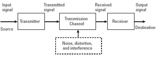
Transmission is a process of transporting information from a point that acts as a transmitter (sender information) to another point that acts as a receiver (receiver of information) where the distance between points can be very far away. The points that there could be many in number and form a telecommunications network. To connect between the network element requires an interface system called the transmission system.
Transmitter: On the transmitter occurs processing the input signal (which includes encoding and modulation) into an output signal corresponding to the transmission channel.
Transmission Channel: Channel is a media transmission link between the transmitter with the receiver. In the process of transmission, the signal will suffer attenuation caused by the transmission channel itself. The farther the distance transmission of data, then the greater the damping will occur.
Receiver: At the receiver, the received signal will be reprocessed. This processing includes filtering is filtering out noise contained in the signal, namely the strengthening of reinforcing the signal amplitude attenuation that has been exposed, equalization, and demodulating and decoding the signal format that is to return to its original shape .
TRANSMISSION CHANNELL
GENERALSubmission of information from an information source to the receiver of information can be accomplished when there is a media delivery system or in between. If the distance between the source of information to the receiver near the information, the transmission system that is used simply through the air. However, if the distance of both remote and very remote, it takes a more complex transmission system. The transmission system can consist of one or more transmission media. The medium used in this system can be either physical media (cable) and non-physical (wireless).Physical transmission medium is a transmission medium that has a physical form. Physical media is generally using cables, wave guide or optical fiber, while the non-physical media such as air or free space (free space). The transmission line is a very important component in the transmission system both wired and wireless systems. In the wireless transmission system, the transmission line is used to connect the transmitter with a transmitter and receiver antenna and receiver.
II. MEDIA TYPES OF TRANSMISSION LINES
Although it is common media used on the transmission channel high frequency or microwaves (microwaves) can be either a conductor or a hollow conductor, but the application can we distinguish in four categories, namely:a. Two parallel wire transmission line (two-wire transmission line)b. Coaxial transmission line (coaxial transmission line)c. Micro strip and strip lined. A wave guide (wave guides)
Two-wire transmission line is only suitable for use in areas lowest frequency of the radio frequency spectrum because the higher frequency transmission line of this type have a very large attenuation. To fix the limitations of two-wire line is then at higher frequencies, use parallel conductor pair is replaced by a pair of conductors are arranged in the same axis, called a "coaxial". With this channel attenuation experienced by electromagnetic fields can be reduced. In the area of higher frequencies (microwaves), coaxial channel is not suitable for electromagnetic wave propagating in the form of radiation penetrating the dielectric material channel so that the damping increases.For that, use a channel in the form of a hollow conductor, called a wave guide. As for linking short distances, at these frequencies typically used so-called strip line transmission lines and
microwave. Based on the physical construction of the transmission line can be distinguished, namely:
2 Two-wire (Twin Lead)Is a two-wire line that consists of a pair of parallel conductors separated by a dielectric material types polythylene. These channels usually have a characteristic impedance 300sampai 600dan widely used to connect a television receiver and the receiver in the area of Very High Frequency (VHF). Physical structure can be seen in Figure 2.1. The dotted lines in the figure indicate the magnetic field arises around the inductor, while the line is not dashed showed electric field.

figure two wire line
3 Coaxial Line
An unbalanced line (unbalanced line), where one of its wires are used as a protector for the other wires in the same axis. Her second wires are separated by a dielectric material Polyethelyne or teflon.
The transmission line is most widely used to transmit radio frequency energy (RF), both the transmitter and receiver system. Impedance characteristics vary, ranging from 50 Ω to 75 Ω. The physical structure and the pattern of the terrain can be seen in Figure 2.2 where the dotted lines indicate the magnetic field, while the line is not dashed showed electric field.

Figure coaxial cable
4 Balanced Shielded LineIs a fusion of two channels of wire line and coaxsial, where his two wires parallel to each other, but to reduce the losses of radiation used protective (shielded) of braided metal fibers such as the coaxial line. This cable has better characteristics than the two-wire cable.
5 Microstrip and striplineIs a form of physical transmission channel in the form of wires that are stiff. The transmission line of this type typically used to work at microwave frequencies region (order GHz) and is used to connect electronic devices within close. Microstrip channel usually made in the form of primed Cabling Board (PCB) with a special material that has low losses at microwave frequencies.
6 pointer wave (waveguides)A waveguide (waveguides) is a single channel that serves to deliver the electromagnetic wave (microwave) with a frequency of 300 MHz - 300 GHz. In fact, the waveguide is a transmission medium that serves to guide the waves in a particular direction. At very high frequencies, above 1 GHz, the transmission line is no longer effective as a medium for the transmission of electromagnetic waves, such as the frequency of the radiation effects of channel attenuation is already too big.The characteristic impedance and wave propagation mode in this type of channel different from previous types. One application of this waveguide is an optical fiber. Although the condition is shaped wires, but the fiber optics transmission line type "waveguide", in this case, a circular waveguide (circular waveguide). Other applications that are as feeder (feeder) on a dish antenna. The waveguide as in the picture

CHARACTERISTICS OF TRANSMISSION LINES
When the relationship between the signal source to the load is in progress, then the signal will propagate in pair wires to the transmission line to the other with a certain speed. The longer the transmission line, the travel time of the signal propagation will be longer. The current flowing along the channel will generate a magnetic field that surrounds the wires and sometimes each other coincides with the magnetic field emanating from the wires around them. The magnetic field generated by an electric current carrying wires, a pile of stored energy in the wires so that it can be considered that the wires are inductive or inductance.Tension that exists between the two wires will generate an electric field. The electric field is also a heap of energy may also benefit coincides with the electric field around them, so that there will be capacitance between two wires. For long channel,
inductance and capacitance will be spread evenly on all the channels and the amount depends on the frequency of signals or waves that propagate therein.Each type of two-wire transmission line also has a conductance value that is a value that represents the possibility of the number of electrons that flow (current) passing through or penetrate dielectrics channels. If the channel is considered to be uniform (uniform), where all values are the same magnitudes along the channel, then small pieces of the channel can be considered to represent the overall length.
IV. IMPEDANCE CHARACTERISTICS
Waves that propagate on the transmission line length is infinite, it will not affect what is at the threshold of the channel. Comparison between threshold voltage and current input channel can actually be considered equal to the ratio between the voltage and current after reaching the other end. It has been suggested that the current and voltage between the two wires looked channels as a transmission line impedance. Impedance is called "Characteristic Impedance (ZO)".
ZO = forward current / voltage forward. ................................... (2.1)
So it can be said that the characteristic impedance is the impedance measured at the threshold of the transmission line of infinite length. When power is propagated on the transmission line infinitely long, then power it
will be absorbed entirely along the channel as a result of the leak current in the capacitance between the conductor and the loss of voltage on the line inductance.

Characteristic Impedance Measurement
In the Figure, it is shown that the impedance seen at the point of 1'-2 'to 1-2 finite) to the right is of ZO well. But with the voltage and current levels are smaller than the voltage at the point 1-2. So if the impedance at the point of 1'-2 'is replaced with a load impedance of ZO, then the impedance of ZO at point 1-2 going well.The characteristic impedance channel lossless (losses-line) can be written as follows:ZO = (root L / C) [W / m] ..... ................................ ................ (2.2)Where :L = total inductance two wires along the line l (Henry)C = capacitance between the two wires length l (Farad)
Large characteristic impedance of a transmission line or waveguide is different and its value is determined by the physical size and the cross section of the dielectric material used as an insulator.
V. LOSS-OF INCOME (LOSSES) ON TRANSMISSION LINES
The voltage and current of a signal that propagates along the transmission line will decrease with distance is longer, this means that the transmission line has a loss.There are generally three kinds of losses contained in the transmission line that is being passed signals, namely:
a. Loss-Loss CopperLoss-loss, among others in the form of power dissipation (I2R) in the form of heat resistive and losses due to the skin effect (skin effect). The higher the frequency, the greater the resistance caused by the skin effect, so this result in losses greater channel. So in addition to the resistance caused by alone, losses of copper is also due to the skin effect, which causes the resistance of the conductor at high frequency also increases.
b. Dielectric Loss LossThis loss incurred due to the warming that has occurred on the wires when the current passed back and forth. Power is transmitted source signal is partially converted into heat which occursthe dielectric material. When the current passed back and forth, then the atomic structure of the dielectric material will undergo a change and the change requires energy. It is this energy that gives rise to power losses. The more difficult the atomic structure of a dielectric material change, the greater its energy needs, which means the greater the power loss caused by it.
c. Loss-Loss Radiation and inductionThis loss occurs due to electromagnetic fields that exist around wires. Induction losses occur when the electromagnetic field around the conductor of a direct hit by a conductor that, consequently lost power at the conductor. Radiation losses are losses that caused the loss of most of the lines of magnetic force due to gushing out of the transmission line.Attenuation arising from losses in transmission line expressed in decibels per unit or neper per unit length.
E1 On Telecommunications Transmission
Is the E1?
E1 is a digital transmission medium used in the telecommunications world. If you enter the working world of telecommunications, you will often encounter such thing as E1. E1 is the standard digital transmission medium used in Indonesia and other countries like the United States. 1 E1 has 30 Time Slot with a speed of 2 Mbps.
So each time slot to send and receive an 8-bit samples, usually encoded according to the law-algorithm A, 8000 times per second (8 x 8000 x 32 = 2.048 million).
It is ideal for voice phone calls where the voice samples into 8 bit numbers at that data rate and reconstructed on the other end. The time slots are numbered from 0 to 31.
One time slot (TS0) is reserved for framing purposes, and alternately transmit a fixed pattern. This allows the receiver to lock on to the beginning of each frame and match each channel in turn.
cables E1

E1 cable has the following characteristics:
The outer skin is the same as wired LAN / UTP is colored gray black ato
2nd layer contained aluminum foil wrappers
a layer of plastic wrap to -3
Color: Blue / White - Green / White, Orange / White - Brown / White, Blue / Red - Green / Red, Orange / Red - brown / red,
There is a grounding wire

E1 cable is usually installed in the terminal DDF. DDF connect between devices that use wired E1 Telecommunication for Transmission media such as connecting to TRC MSC, MSC to BSC, BSC to Transmission.
Well, so first of this topic, in the next post I will discuss how to install the E1 cable on DDF.

X . IIIIII
Transmission on the lights


Do lenses affect light transmission?
Photographic lenses are made of several elements of very pure glass, each element being carefully coated to limit reflection. However, a portion of the light is lost in the optical system due to residual reflection and absorption.The transmission factor (the proportion of light that actually makes its way to the sensor) depends on the optical formula (the number of lenses, the glass and coating formulas) and to a lesser degree on the shooting parameters.
As a measure of transmission, DxOMark reports the T-stop, defined as the f-number of a lens with 100% perfect transmission, and resulting in the same illumination of the sensor at the image center as the lens to be measured.
Light Absorption, Reflection, and Transmission
We have previously learned that visible light waves consist of a continuous range of wavelengths or frequencies. When a light wave with a single frequency strikes an object, a number of things could happen. The light wave could be absorbed by the object, in which case its energy is converted to heat. The light wave could be reflected by the object. And the light wave could be transmitted by the object. Rarely however does just a single frequency of light strike an object. While it does happen, it is more usual that visible light of many frequencies or even all frequencies is incident towards the surface of objects. When this occurs, objects have a tendency to selectively absorb, reflect or transmit light certain frequencies. That is, one object might reflect green light while absorbing all other frequencies of visible light. Another object might selectively transmit blue light while absorbing all other frequencies of visible light. The manner in which visible light interacts with an object is dependent upon the frequency of the light and the nature of the atoms of the object. In this section of Lesson 2 we will discuss how and why light of certain frequencies can be selectively absorbed, reflected or transmitted.Visible Light Absorption
Atoms and molecules contain electrons. It is often useful to think of these electrons as being attached to the atoms by springs. The electrons and their attached springs have a tendency to vibrate at specific frequencies. Similar to a tuning fork or even a musical instrument, the electrons of atoms have a natural frequency at which they tend to vibrate. When a light wave with that same natural frequency impinges upon an atom, then the electrons of that atom will be set into vibrational motion. (This is merely another example of the resonance principle introduced in Unit 11 of The Physics Classroom Tutorial.) If a light wave of a given frequency strikes a material with electrons having the same vibrational frequencies, then those electrons will absorb the energy of the light wave and transform it into vibrational motion. During its vibration, the electrons interact with neighboring atoms in such a manner as to convert its vibrational energy into thermal energy. Subsequently, the light wave with that given frequency is absorbed by the object, never again to be released in the form of light. So the selective absorption of light by a particular material occurs because the selected frequency of the light wave matches the frequency at which electrons in the atoms of that material vibrate. Since different atoms and molecules have different natural frequencies of vibration, they will selectively absorb different frequencies of visible light.Visible Light Reflection and Transmission
Reflection and transmission of light waves occur because the frequencies of the light waves do not match the natural frequencies of vibration of the objects. When light waves of these frequencies strike an object, the electrons in the atoms of the object begin vibrating. But instead of vibrating in resonance at a large amplitude, the electrons vibrate for brief periods of time with small amplitudes of vibration; then the energy is reemitted as a light wave. If the object is transparent, then the vibrations of the electrons are passed on to neighboring atoms through the bulk of the material and reemitted on the opposite side of the object. Such frequencies of light waves are said to be transmitted. If the object is opaque, then the vibrations of the electrons are not passed from atom to atom through the bulk of the material. Rather the electrons of atoms on the material's surface vibrate for short periods of time and then reemit the energy as a reflected light wave. Such frequencies of light are said to be reflected.Where Does Color Come From?
The color of the objects that we see is largely due to the way those objects interact with light and ultimately
reflect or transmit it to our eyes. The color of an object is not
actually within the object itself. Rather, the color is in the light
that shines upon it and is ultimately reflected or transmitted to our
eyes. We know that the visible light spectrum consists of a range of
frequencies, each of which corresponds to a specific color. When visible
light strikes an object and a specific frequency becomes absorbed, that
frequency of light will never make it to our eyes. Any visible light
that strikes the object and becomes reflected or transmitted to our eyes
will contribute to the color appearance of that object. So the color is
not in the object itself, but in the light that strikes the object and
ultimately reaches our eye. The only role that the object plays is that
it might contain atoms capable of selectively absorbing one or more
frequencies of the visible light that shine upon it. So if an object
absorbs all of the frequencies of visible light except for the frequency
associated with green light, then the object will appear green in the
presence of ROYGBIV.
And if an object absorbs all of the frequencies of visible light except
for the frequency associated with blue light, then the object will
appear blue in the presence of ROYGBIV.
ultimately
reflect or transmit it to our eyes. The color of an object is not
actually within the object itself. Rather, the color is in the light
that shines upon it and is ultimately reflected or transmitted to our
eyes. We know that the visible light spectrum consists of a range of
frequencies, each of which corresponds to a specific color. When visible
light strikes an object and a specific frequency becomes absorbed, that
frequency of light will never make it to our eyes. Any visible light
that strikes the object and becomes reflected or transmitted to our eyes
will contribute to the color appearance of that object. So the color is
not in the object itself, but in the light that strikes the object and
ultimately reaches our eye. The only role that the object plays is that
it might contain atoms capable of selectively absorbing one or more
frequencies of the visible light that shine upon it. So if an object
absorbs all of the frequencies of visible light except for the frequency
associated with green light, then the object will appear green in the
presence of ROYGBIV.
And if an object absorbs all of the frequencies of visible light except
for the frequency associated with blue light, then the object will
appear blue in the presence of ROYGBIV.Consider the two diagrams below. The diagrams depict a sheet of paper being illuminated with white light (ROYGBIV). The papers are impregnated with a chemical capable of absorbing one or more of the colors of white light. Such chemicals that are capable of selectively absorbing one or more frequency of white light are known as pigments. In Example A, the pigment in the sheet of paper is capable of absorbing red, orange, yellow, blue, indigo and violet. In Example B, the pigment in the sheet of paper is capable of absorbing orange, yellow, green, blue, indigo and violet. In each case, whatever color is not absorbed is reflected.

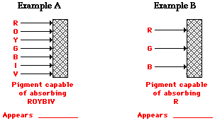
Transmission of Light Defined
Visible light is the reason we are able to see anything at all. Light moves as a wave, bouncing off objects so we can see them. Without it, we'd be in complete darkness. But, in physics, light can refer to any kind of electromagnetic wave: radio waves, microwaves, infrared, visible light, ultraviolet, X-rays, or gamma rays.When you shine light on an object, a number of things can happen. Reflection is when light bounces off of a surface. Specular reflection is when light reflects off of a shiny surface like a mirror. Diffuse reflection, however, is when light illuminates a dull object.
Another thing it can do is move through the material, and depending on exactly how it does this, we might call it transmission, refraction, or absorption. We will discuss each in more detail in this lesson, but transmission of light is when light waves move all the way through a material without being absorbed.
Transmittance
When light moves through a transparent (or semi-transparent) material, it can be transmitted, absorbed, or reflected. The transmittance of a material is the proportion of the incident (approaching) light that moves all the way through to the other side.For example, let's say you're shining a flashlight on a semi-transparent glass block. You start off with 100% of your incident light. The first thing that happens is that 30% of that light is reflected off the outer surface of the glass. This leaves you with 70% to continue through the glass block. Another 50% of the light is absorbed by the molecules inside the glass block itself. That leaves you with 20% that emerges from the opposite side. So you could say that the glass block has a transmittance of 20%.
The transmittance of a material depends on its thickness, but it also depends on the type of light (or electromagnetic waves) you are using. A material might have a different transmittance for visible light than it does for infrared, or X-rays. This is why hospital X-rays go through your skin until they reach the bones,even though visible light does not .


X . IIIIIII
Transmission on biology
Synaptic Transmission 
nerve cell gif nerve cell transmission
How Antidepressants Work ?
Causes of Depression

Research indicates that patients with MDD either do not have enough serotonin or norepinephrine in these areas of the brain or have an imbalance between the two types of neurotransmitters. Antidepressants are designed to increase the levels of these neurotransmitters in the limbic system. So, to understand how antidepressants work, we must look at the process of neurotransmission.
Note
|

Nerve Communication
 |
- The presynaptic cell (sending cell) makes serotonin (5-hydroxytryptamine, 5HT) from the amino acid tryptophan and packages it in vesicles in its end terminals.
- An electrochemical nerve signal passes down the presynaptic cell into its end terminals.
- The nerve signal stimulates the vesicles containing serotonin to fuse with the cell membrane and dump serotonin into the synaptic cleft.
- Serotonin passes across the synaptic cleft, binds with special proteins called receptors on the membrane of the postsynaptic cell (receiving cell) and sets up a new electrochemical signal in that cell (the signal can stimulate or inhibit the postsynaptic cell). Serotonin fits with its receptor like a lock and key.
- The remaining serotonin molecules in the cleft and those released by the receptors after use get destroyed by enzymes in the cleft (monoamine oxidase (MAO) and catechol-o-methyl transferase (COMT)). Some get taken up by specific transporters on the presynaptic cell (reuptake). In the presynaptic cell, the absorbed serotonin molecules get destroyed by MAO and COMT. This enables the nerve signal to be turned "off."
SSRI and Tricyclic Antidepressants
 Stephen Chernin/Getty Images Prozac is one of the most prescribed antidepressants. |
Antidepressants are classified according to which neurotransmitters they affect and how they affect them. Let's look at the different types of antidepressants.
Selective Serotonin Reuptake Inhibitors (SSRI)
SSRIs, the most frequently prescribed antidepressants, were introduced in the mid-1980s. SSRIs block the transport of serotonin back into the presynaptic cell. This action increases the concentration of serotonin in the synaptic cleft, increasing stimulation of the postsynaptic cells. SSRIs include the following drugs:
- fluoxetine (ProzacTM)
- paroxetine (PaxilTM)
- sertraline (ZoloftTM)
- fluvoxamine (LuvoxTM)
- citalopram (CelexaTM)
- escitalopram (LexaproTM)
To minimize side effects that might cause a patient to stop using the drug, primary health-care providers usually start SSRIs at low doses and slowly increase to the target dose over four to six weeks. Such side effects include nausea, dizziness, vertigo, vomiting, insomnia, anorexia, anxiety and sexual dysfunction.
Tricyclic Antidepressants and Selective Norepinephrine Reuptake Inhibitors
Tricyclic antidepressants were introduced in the late 1950s and early 1960s. Like SSRIs, these compounds block the reuptake of norepinephrine by the presynaptic cell, thereby increasing its concentration in the synaptic cleft. Tricyclic antidepressants include:
- nortryptiline (PamelorTM)
- maprotiline (LudiomilTM)
- desipramine (NorpramineTM)
- amitryptiline (ElavilTM)
- clomipramine (AnafranilTM)
- imipramine (TrofranilTM)
Tricyclic antidepressants are nonselective inhibitors of norepinephrine reuptake because their chemical structures look like norepinephrine. Reboxetine (EdronaxTM) is a more specific reuptake inhibitor because it binds better to the reuptake transporter, but it isn't available in the United States.
SNRI, MAOI and NaSSA Antidepressants
These drugs were introduced in the mid-1990s and block the reuptake of both serotonin and norepinephrine by binding to the transporters of these neurotransmitters on the presynaptic cell. SNRIs include:
- bupropion (WellbutrinTM) -- blocks dopamine and norepinephrine reuptake as well
- duloxetine (CymbaltaTM)
- venlafaxine (EffexorTM)
 |
Monoamine Oxidase Inhibitors (MAOI)
An enzyme called monoamine oxidase can degrade serotonin and norepinephrine in the synaptic cleft and presynaptic cell. MAOIs block this degradation, increasing the concentration of the neurotransmitters. MAOIs include:
- phenelzine (NardilTM)
- tranylcypromine (ParnateTM)
- selegiline (EldeprylTM)
- isocarboxazid (MarplanTM)
- moclebemice (ManerixTM)
Noradrenergic and Specific Serotonin Antidepressants (NaSSA)
Some of these compounds were introduced in the mid-1980s and others even more recently. NaSSAs block negative feedback effects on norepinephrine and serotonin secretion by the presynaptic cell. This action increases the concentrations of these neurotransmitters in the synaptic cleft. They also block some serotonin receptors on the postsynaptic cell, which enhances serotonin neurotransmission. These compounds include
- Mirtazipine (RemeronTM)
- Trazodone (DesyrelTM)
- Nefazodone (SerzoneTM)
- Mianserin (BolvidionTM)
Remember that the available antidepressants are about equally effective in treating MDD. So, choices are based on patient's age, family history, drug tolerance, side effects and past response to antidepressants.
Acute phase
Here, the goal is to get the patient into remission (a state with minimal symptoms). This usually involves beginning antidepressant therapy. Usually, SSRIs are the drug of choice, especially for children and older patients, because they can be used in lower dosages with the fewest side effects. It takes about four to six weeks for any antidepressant to show effects.
Augmenting Antidepressants
Sometimes
MDD patients show other symptoms (changes in mood, delusions,
hallucinations, changes in energy metabolism) partially due to
antidepressant side effects or to other types of depression (like
bipolar disorder -- periods of happiness interspersed by periods of
severe depression). So, primary care providers may add other
medications to antidepressant therapy.
|
Continuation phase
After remission begins, doctors try to eliminate remaining symptoms, restore the patient to his or her level of function before the MDD episode and prevent recurrence of further MDD episodes. During this time, the levels of antidepressant therapy and psychotherapy used to achieve remission are maintained. If, after six months, there is no relapse, medication might be discontinued gradually over several weeks. The continuation phase of treatment could last six to 12 months.
Maintenance phase
This phase is most important for patients with annual episodes of depression. During this time, patients should be monitored regularly. Antidepressant therapies sometimes have to be reinitiated. Psychotherapy and patient education are especially important. The maintenance phase can last one to three years.
Special populations and depression therapy
When deciding on therapy, some clinically depressed patients require special considerations:
- Bipolar disorder -- these patients have extreme mood swings (periods of excessive high spirits followed by severe depressive episodes). Typically, the antidepressants are augmented with mood stabilizers.
- Children/adolescents -- The SSRI fluoxetine is the only effective (and approved) antidepressant for this age group. There have been reports that children on antidepressants are more likely to commit suicide than those who are not on antidepressants; while some data suggest that this may be true, it has not been proven conclusively. Primary care providers need to weigh the risks of antidepressant therapy versus untreated depression. Most often, treatment carries fewer risks of suicide than non-treatment.
- Pregnant/postpartum women -- Depression can be a common symptom during pregnancy and postpartum -- it usually corrects itself, but sometimes severe depression must be treated (in about 10 percent of pregnant/postpartum women). Antidepressants can pass to the fetus and through breast milk. The effects of antidepressants on the developing fetus and newborn are not well known. Therefore, doctors should carefully consider the risks and benefits of treatment.
another example transmission biology :

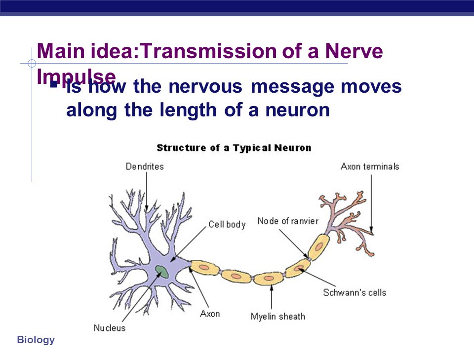

Prion-like transmission of protein aggregates in neurodegenerative diseases
Protein folding proceeds through intermediates, which expose hydrophobic amino acid side chains on their surfaces that are normally buried in the interior of the native state, and are therefore prone to self-associate into non-native oligomers (see the figure, part a). Molecular chaperones of the heat shock protein 70 (HSP70) family interact transiently with these aggregation-prone surfaces (see the figure, part b). They either compete with self-association or favour the formation of native contacts and help maintain intermediates in a monomeric, folding-competent state. Mutations or polymorphisms can destabilize the native state or decrease the efficiency of folding. Insufficient amounts of molecular chaperones also affect folding efficiency. Incompletely folded proteins are tagged with polyubiquitin chains, which direct them to the 26S proteasome for degradation (see the figure, part c). Molecular chaperones contribute to this process by maintaining the proteins in a state that can be unfolded by the 26S proteasome. Proteins that escape degradation by the 26S proteasome can be degraded by lysosomes through macroautophagy (see the figure, part d). Autophagic degradation begins with the capture of the substrate proteins (or aggregates) into phagophores that mature into autophagosomes — a vesicular structure enclosed by two concentric lipid bilayer membranes. Autophagosomes fuse with organelles of the endosomal and lysosomal pathways to form autolysosomes that, endowed with acidic pH and lysosomal hydrolases, are able to degrade proteins without the need to unfold them. Finally, the interaction of protein aggregates with the minus end-directed microtubule motor cytoplasmic dynein results in their accumulation around the centrosome or microtubule organizing centre (see the figure, part e). This process may facilitate the capture of aggregates by macroautophagy or may serve to concentrate potentially toxic aggregation nuclei in a defined region of the cell.
Native (sphere) prion molecules undergo conformational changes that lead to an abnormal (cube) form (see the figure; part a, step 1). This event is unfavourable because the abnormal form is either unstable (part a,
step 2) or sensitive to clearance. According to the 'template
assistance' model, prions in their abnormal form interact with native
prions (part a, step 3) and convert them into the abnormal form (part a,
step 4). The alternative 'seeded polymerization' model proposes that
abnormal prions have the ability to interact with molecules in a similar
state (part a, step 5). The oligomeric species
formed are unstable because the intermolecular interactions do not
outweigh the entropic cost of binding. They grow by the incorporation of
abnormal prion molecules (part a, step 6) and dissociate (part a,
step 7) until a stable nucleus is formed. Such a stable prion aggregate
can then grow indefinitely from one or both ends and can also break
into smaller fragments (part a, step 8) that act as nuclei (part a, step 6).
Prion aggregates bind to native prion molecules or receptor proteins attached to the cell membrane, and are internalized by endocytosis (part b, step 1). They reach the cytoplasm, by an unknown process, where they grow by the incorporation of cytosolic prions. They can move along the axon in one direction or another (part b, step 2) and can reach neighbour cells through axon–dendrite connections (part b, step 3) and nanotubes (part b, step 4).
Prions and polypeptides involved in Parkinson's, Alzheimer's and Huntington's diseases form aggregates that resist protein denaturation treatments (see the figure, part c). This process can be monitored experimentally. Stable oligomer formation is thermodynamically unfavourable and this is reflected by a nucleation phase. The stable oligomers elongate in an exponential manner until the soluble protein concentration reaches the critical concentration, above which assembly occurs. These events give a sigmoidal shape to the assembly kinetic (see the figure, part c; green curve). The nucleation phase is abolished (see the figure, part c; orange curve) when preformed aggregates that act as seeds are added to the protein solution.

Protein folding proceeds through intermediates, which expose
hydrophobic amino acid side chains on their surfaces that are normally
buried in the interior of the native state, and are therefore prone to
self-associate into non-native oligomers (see the figure, part a).
Molecular chaperones of the heat shock protein 70 (HSP70) family
interact transiently with these aggregation-prone surfaces (see the
figure, part b). They either compete with
self-association or favour the formation of native contacts and help
maintain intermediates in a monomeric, folding-competent state.
Mutations or polymorphisms can destabilize the native state or decrease
the efficiency of folding. Insufficient amounts of molecular chaperones
also affect folding efficiency. Incompletely folded proteins are tagged
with polyubiquitin chains, which direct them to the 26S proteasome for
degradation (see the figure, part c). Molecular
chaperones contribute to this process by maintaining the proteins in a
state that can be unfolded by the 26S proteasome. Proteins that escape
degradation by the 26S proteasome can be degraded by lysosomes through
macroautophagy (see the figure, part d).
Autophagic degradation begins with the capture of the substrate proteins
(or aggregates) into phagophores that mature into autophagosomes — a
vesicular structure enclosed by two concentric lipid bilayer membranes.
Autophagosomes fuse with organelles of the endosomal and lysosomal
pathways to form autolysosomes that, endowed with acidic pH and
lysosomal hydrolases, are able to degrade proteins without the need to
unfold them. Finally, the interaction of protein aggregates with the
minus end-directed microtubule motor cytoplasmic dynein results in their
accumulation around the centrosome or microtubule organizing centre
(see the figure, part e). This process may
facilitate the capture of aggregates by macroautophagy or may serve to
concentrate potentially toxic aggregation nuclei in a defined region of
the cell.
Prion aggregates bind to native prion molecules or receptor proteins attached to the cell membrane, and are internalized by endocytosis (part b, step 1). They reach the cytoplasm, by an unknown process, where they grow by the incorporation of cytosolic prions. They can move along the axon in one direction or another (part b, step 2) and can reach neighbour cells through axon–dendrite connections (part b, step 3) and nanotubes (part b, step 4).
Prions and polypeptides involved in Parkinson's, Alzheimer's and Huntington's diseases form aggregates that resist protein denaturation treatments (see the figure, part c). This process can be monitored experimentally. Stable oligomer formation is thermodynamically unfavourable and this is reflected by a nucleation phase. The stable oligomers elongate in an exponential manner until the soluble protein concentration reaches the critical concentration, above which assembly occurs. These events give a sigmoidal shape to the assembly kinetic (see the figure, part c; green curve). The nucleation phase is abolished (see the figure, part c; orange curve) when preformed aggregates that act as seeds are added to the protein solution.
X . IIIIIIII
TRANSMISSION ON ASTRONOMY

Atmospheric Transmission--Good News and Bad News
It is not coincidence that our eyes are sensitive to optical light waves. Optical light can travel nearly unimpeded through our atmosphere, and so our eyes have adapted themselves to be sensitive at these wavelengths. For thousands of years, optical light was our only "window" on the Universe, and even then the primary "instrument" was the naked eye. When Galileo first turned his telescope skyward, he opened this window a little farther and saw many marvelous things for the first time. Yet, as is discussed elsewhere in these pages, optical light is a small portion of the entire range of electromagnetic radiation. How much more could we learn about the Universe if we could use the entire EM spectrum?
Most of the rest of the EM spectrum gets absorbed or blocked by the atmosphere, and it's a good thing, too! Just a tiny portion of ultraviolet light leaking through the atmosphere is enough to give us a painful sunburn if we aren't careful. Can you imagine what earth would be like if ultraviolet or X-ray light could get through the atmosphere? Suffice it to say that we wouldn't be around to "see" it--we would have long since been fried by our own sun! The atmosphere is "good news" from the perspective of life on earth. But the atmosphere is "bad news" if we want to see the Universe at these wavelengths.
Radio light was the first window after the optical one to be used for astronomy. This is because certain portions of the radio spectral region can pass through the atmosphere and be detected from cosmic sources. As a matter of fact, radio astronomy grew out of the development of radar techniques during World War II. As the first sensitive radio receivers were built, users noticed a persistent faint radio noise that they could not identify. It turns out this "noise" was due to cosmic sources of radio radiation being picked up by accident. Radio astronomy was born!
Certain portions of the infrared spectral region can get through the atmosphere, at least partially. Observatories at high altitude (above most of the water vapor in the atmosphere) can do quite well in certain small wavelength ranges. And special infrared telescopes have been flown on high-flying aircraft to open this window even further. However, many portions of the infrared spectrum get completely absorbed in the atmosphere.
While much can be learned from optical observations, there is also much unique information to be gained from observations in other wavelength ranges that are hidden by the curtain of our atmosphere. For astronomers to observe in most of the EM spectrum, we need to get telescopes in space. It has only been over the last 35 years that this has been possible, with rockets that can lift special telescopes above the atmospheric curtain. Telescopes have now been flown to observe across the entire spectrum! For astronomers, that's good news!
Astronomical filter

Ultraviolet
filters used in astronomy for blocking the ultraviolet radiation, which
causes the camera to heat up when photographing (without affecting the
image).
Most astronomical filters work by blocking a specific part of the color spectrum above and below a bandpass, significantly increasing the signal to noise of the interesting wavelengths, and so making the object more visible, 'contrasty', or defined. While the color filters transmit certain colors from the spectrum and are usually used for observation of the planets and the Moon, the polarizing filters work by adjusting the brightness, and are usually used for the Moon. The broadband and narrowband filters transmit the wavelengths that are emitted by the nebulae (by the Hydrogen and Oxygen atoms), and are frequently used for reducing light pollution.
Solar filters
Solar filters block most of the sunlight to avoid any damage to the eyes. They are usually made from a durable glass or a plastic film which transmits 1/100,000th of the light. Film filters are used over the aperture of the telescope and do not heat up significantly, whereas glass filters are used near the objective end causing them to heat up greatly and it is not unknown for them to shatter from thermal shock. Glass solar filters are therefore not recommended by most experts and some stockists refuse to sell them or remove them from telescope packages. "Solar filters designed to thread into eyepieces that are often provided with inexpensive telescopes are also unsafe. These glass filters can crack unexpectedly from overheating when the telescope is pointed at the Sun, and retinal damage can occur faster than the observer can move the eye from the eyepiece."They are used for observation, photography, and for viewing the sun as a yellow-orange disk. With a telescope, these filters can view the details of the sun directly and safely, especially the sunspots and granulation of the surface.The Herschel Wedge is a prism based device used in conjunction with a neutral density filter that directs most of the heat and ultra violet light out of the telescope, generally giving better results than most filters. Another filter used for solar observing is the hydrogen-alpha filter, which transmits the H-alpha spectral line. These filters can view the solar flares and prominences that are not visible in the normal solar filters.
Color filters

A blue color filter
Professional filters are also colored, but their bandpass centers are placed around other midpoints (such as in the UBVRI and Cousins systems).
Some of common color filters and their uses are:
- Chromatic aberration filters: Used for reduction of the purplish halo, caused by chromatic aberration of refracting telescopes. Such halo can obscure features of bright objects, especially Moon and planets. These filters have no effect on observing faint objects.
- Red: Reduces sky brightness, particularly during daylight and twilight observations. Improves definition of maria, ice, and polar areas of Mars. Improves contrast of blue clouds against background of Jupiter and Saturn.
- Deep yellow: Improves resolution of atmospheric features of Venus, Jupiter (especially in polar regions), and Saturn. Increases contrast of polar caps, clouds, ice and dust storms on Mars. Enhances comet tails.
- Dark green: Improves cloud patterns on Venus. Reduces sky brightness during daylight observation of Venus. Increases contrast of ice and polar caps on Mars. Improves visibility of the Great Red Spot on Jupiter and other features in Jupiter atmosphere. Enhances white clouds and polar regions on Saturn.
- Medium blue: Enhances contrast of Moon. Increases contrast of faint shading of Venus clouds. Enhances surface features, clouds, ice and dust storms on Mars. Enhances definition of boundaries between features in atmospheres of Jupiter and Saturn. Improves definition of comet gas tails.
Moon filters
Neutral density filters, also known in astronomy as Moon filters, are another approach for contrast enhancement and glare reduction. They work simply by blocking some of the object's light to enhance the contrast. Neutral density filters are mainly used in traditional photography, but are used in astronomy to enhance lunar and planetary observations.Polarizing filters
Polarizing filters adjust the brightness of images to a better level for observing, but much less so than solar filters. With these types of filter, the range of transmission varies from 3% to 40%. They are usually used for the observation of the Moon, but may also be used for planetary observation. They consist of two polarizing layers in a rotating aluminum cell, which changes the amount of transmission of the filter by rotating them. This reduction in brightness and improvement in contrast can reveal the lunar surface features and details, especially when it is near full. Polarizing filters should not be used in place of solar filters designed specially for observing the sun.Nebular filters
Narrowband

The three main spectral lines that Narrowband filters transmit
Broadband
The broadband, or light pollution reduction (LPR), filters are nebular filters that block the light pollution in the sky and transmit the H-alpha, H-beta, and O III spectral lines, which makes observing nebulae from the city and light polluted skies possible. These filters block the Sodium and Mercury vapor light, and also block the natural skyglow such as the auroral light The broadband filters differ from the narrowband with the range of wavelengths transmission. LED lighting is more broadband so this is not blocked although white LEDs have from themselves a considerably lower output around 480 nm which is close to O III and H-beta wavelength. The broadband filters have a wider range because the narrower transmission range causes a fainter image of sky objects, and since the work of these filters is revealing the details of nebulae from light polluted skies, it has a wider transmission for more brightness.These filters are particularly designed for nebulae observing, are not useful with other deep sky objects. However, it can improve the contrast between the DSOs and the background sky, which may clarify the image.Transmission and time Efficiency
Photon collecting efficiency
1: Efficiency
Have you ever thought about how efficient you collect/detect photons?
Every lens surface transmit about 99%, every mirror surface reflect about 92%, it could be worse or it could be better.
But there is a system of optical parts and together they make up significant losses.
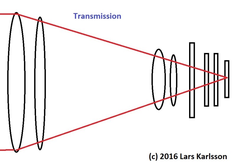
And then there is also limitations in the sensor efficiency, the QE.
And you also loose time between every sub image you take. I have collected this losses in a table so you can see the scary result.
Also assume a monochrome camera with filter wheel to make rgb color images.
Note. Each lens or filter have two surfaces.
Each line is the contribution of efficiency.
It doesn't look too bad, we have a throughput of about 82% of the photons in the refractor and 62% in the reflector.
Bit it's a bit worse, this was at the center of sensor, vignetting problems maybe will reduce it by half at the corners.
But is this the whole true story?


X . IIIIIIIII
Transmission on weapons


It has been said that outer space is the ultimate high ground for military engagements, and if we examine orbital space-based weapon platforms seen in sci-fi, it seems that our future will include orbital space as a future battleground. Currently, orbital space is used by military organizations and intelligence services for all manner of satellites that watch and listen. But, could orbital space be militarized? Could we have orbital artillery as predicted by science fiction and the cancelled SDI program? In this blogpost of FWS, we will be discussing orbital artillery and orbital bombardment.
The idea of the militarization of outer space was a real fear in the heady days of the Space Race between the USA and USSR. The Soviets had put up military space stations and a few of them were armed with an 23mm cannon. There was also worry that the arms race would continue into the void of outer space with orbital nuclear missile platforms. In 1967, the United Nations passed the Outer Space Treaty that established legal frameworks on the ownership of celestial bodies, like Luna and Mars. One of the elements of the treaty was preventing orbital weapon platforms that bore nuclear weapons and othe r WMDs. This treaty shaped the research on orbital weapon systems.
The Types of Orbital Artillery
Directed Energy
 One
of the most common type of orbital bombardment/artillery is directed
energy beams that can be used more like knife than an club or even a
shower of directed energy death-laser-beams that tear through the
planetary surface. Shooting freaking laser beams on the surface of Luna
is much easier than shooting them down to Earth or Mars, due to the
atmosphere. Any military-grade lethal DE beam would have to be powerful
enough to punch through the atmosphere and hit the target with enough
energy to be lethal. It is unlikely that lasers will be the orbital DEW
system of choice, instead, it is likely that particle beam DEWs would
fulfill that role. The use of DE is common in science fiction "kill
satellites" as seen in works like Akira.
One
of the most common type of orbital bombardment/artillery is directed
energy beams that can be used more like knife than an club or even a
shower of directed energy death-laser-beams that tear through the
planetary surface. Shooting freaking laser beams on the surface of Luna
is much easier than shooting them down to Earth or Mars, due to the
atmosphere. Any military-grade lethal DE beam would have to be powerful
enough to punch through the atmosphere and hit the target with enough
energy to be lethal. It is unlikely that lasers will be the orbital DEW
system of choice, instead, it is likely that particle beam DEWs would
fulfill that role. The use of DE is common in science fiction "kill
satellites" as seen in works like Akira.
Kinetic Projectiles or "Rods from God"

Unlike orbiting nuclear weapons, kinetic projectiles are legal under the 1967 Outer Space Treaty (as well as space-based lasers) and instead of those dirty nuclear weapons, these rods from god are able to delivery some serious punch without the nasty after effects of nukes. If we examine the USAF's proposed kinetic bombardment system, these six meter long tungsten rods impacted the surface of the Earth with the road going at MACH 10 (7,700 MPH). The impact of the rob was equal to between 10 and 120 tons of TNT, less than the 2,000 tons of TNT that the Fat Man and Little Boy Atomic bombs produced when dropped on Japan. Unlike long-range bombers like the B-52 and B-1, the tungsten rods at able to reach their Earth-based target at between 10-15 minutes, and are extremely difficult to intercept like ICBMs or bombers. While this form of orbital artillery is not as effective as nuclear weapons, they can be used in more of combat supporting role and even pre-invasion artillery softening up operations, along with being a effective "bunker buster" system. The data for this section, comes from the Game Theory video: https://www.youtube.com/watch?v=rx5XyspHldk
Reentry Vehicle
 On current ICBMs, re-entry vehicles are used to delivery the nuclear
payload safety through the atmosphere and blow the holy jesus out of
your enemy. This could be another way to delivery orbital artillery
rather than kinetic rods, especially at longer ranges than just orbital
space. Reentry vehicles could also pack more countermeasures than just
speed to defend themselves. While the RV would be good method of
delivering nuclear weapons and other WMDs, they would make for a poor
orbital artillery method.
On current ICBMs, re-entry vehicles are used to delivery the nuclear
payload safety through the atmosphere and blow the holy jesus out of
your enemy. This could be another way to delivery orbital artillery
rather than kinetic rods, especially at longer ranges than just orbital
space. Reentry vehicles could also pack more countermeasures than just
speed to defend themselves. While the RV would be good method of
delivering nuclear weapons and other WMDs, they would make for a poor
orbital artillery method.
Controlled Meteors
 From the Centauri mass driver bombardment of Narn to the Fithp "foot"
being shot into the Indian Ocean by rocket motors, meteors have been an
excellent form of orbital bombardment, and the oldest...after all,
humans are only around due to an meteor strike. Some science fiction
works, like Babylon 5 and Starblazers space fleets use
controlled meteors and asteroids as a form of orbital bombardment.
However, this comes with certain risks...any space rock too big, and you
could completely wipe out all life on the planet along with the
ecosystem...unless that is your goal, then have at it, and bombing into
extinction!
From the Centauri mass driver bombardment of Narn to the Fithp "foot"
being shot into the Indian Ocean by rocket motors, meteors have been an
excellent form of orbital bombardment, and the oldest...after all,
humans are only around due to an meteor strike. Some science fiction
works, like Babylon 5 and Starblazers space fleets use
controlled meteors and asteroids as a form of orbital bombardment.
However, this comes with certain risks...any space rock too big, and you
could completely wipe out all life on the planet along with the
ecosystem...unless that is your goal, then have at it, and bombing into
extinction!
The Dangers of Orbital Artillery/Bombardment
 There is nothing more devastating to soldiers than when supporting
artillery from field guns to CAS goes wrong. Despite the advancement in
battlefield technology, artillery fire can go horribly wrong, and your
own forces pay the price. That is the danger today, and that will be a
danger tomorrow. Even in video games, nothing is worse than calling down
a strike and it wiping out friendly forces. If and when orbital based
weaponry becomes a reality, the risk of troops calling down artillery
could go horribly wrong, and given the power of rods-from-god, a
miscalculation by the director, and an entire city or taskforce could be
wiped out. Then there is another risk: overuse. Some orbital
bombardment systems have been projected in science fiction as pinpoint
laser DE beams able to slice-and-dice enemy tanks and infantry
formations. However, the reality is that kinetic bombardment systems
would be very powerful, and their overuse or misuse could bring about
massive destruction and even nuclear winter conditions. This applies
more so to the use of asteroids and meteors as a form of kinetic
bombardment, too much and you ruin the planetary ecosystem, and affect
global climate change.
There is nothing more devastating to soldiers than when supporting
artillery from field guns to CAS goes wrong. Despite the advancement in
battlefield technology, artillery fire can go horribly wrong, and your
own forces pay the price. That is the danger today, and that will be a
danger tomorrow. Even in video games, nothing is worse than calling down
a strike and it wiping out friendly forces. If and when orbital based
weaponry becomes a reality, the risk of troops calling down artillery
could go horribly wrong, and given the power of rods-from-god, a
miscalculation by the director, and an entire city or taskforce could be
wiped out. Then there is another risk: overuse. Some orbital
bombardment systems have been projected in science fiction as pinpoint
laser DE beams able to slice-and-dice enemy tanks and infantry
formations. However, the reality is that kinetic bombardment systems
would be very powerful, and their overuse or misuse could bring about
massive destruction and even nuclear winter conditions. This applies
more so to the use of asteroids and meteors as a form of kinetic
bombardment, too much and you ruin the planetary ecosystem, and affect
global climate change.
Defense Against Orbital Weapon Platforms
 Oddly, most military organizations and weapons manufacturers have
already put weapon systems into place to counter satellites and the
possibility of orbital based weapon platforms. The anti-satellite
missile that can be deployed from strike fighters like the American F-15
Eagle, or land based launcher systems, or even submarines/naval
vessels. These kinetic-kill warheads are fitted to small multi-stage
rockets have proven effective against satellites, and could be effective
against orbital weapons platforms as well. While an orbital weapon
system could be camouflaged as something else, the moment it began
firing, the game would be up, and ASAT weapon systems would be utilized.
Of course, one way around this could be the assumed role of the X-37B
USAF drone-shuttle: an mobile launcher system based around an space
plane design. In the end, one of the best defenses against orbital based
weapon platforms is wiping out their command & control system back
here on Earth. Whether by direct action, like we saw in Call of Duty: GHOSTS or an EMP blast, any would be effective in taking out one method of controlling orbital weapon platforms.
Oddly, most military organizations and weapons manufacturers have
already put weapon systems into place to counter satellites and the
possibility of orbital based weapon platforms. The anti-satellite
missile that can be deployed from strike fighters like the American F-15
Eagle, or land based launcher systems, or even submarines/naval
vessels. These kinetic-kill warheads are fitted to small multi-stage
rockets have proven effective against satellites, and could be effective
against orbital weapons platforms as well. While an orbital weapon
system could be camouflaged as something else, the moment it began
firing, the game would be up, and ASAT weapon systems would be utilized.
Of course, one way around this could be the assumed role of the X-37B
USAF drone-shuttle: an mobile launcher system based around an space
plane design. In the end, one of the best defenses against orbital based
weapon platforms is wiping out their command & control system back
here on Earth. Whether by direct action, like we saw in Call of Duty: GHOSTS or an EMP blast, any would be effective in taking out one method of controlling orbital weapon platforms.
Real-World Examples of Orbital Weapon System
The THOR Project (USA 1950's-today)
 Boeing
in the 1950's became working on a kinetic bombardment system called
THOR. The idea was to have an orbital artillery system that could not
provoke a nuclear exchange, and THOR later would conform to the 1967
Outer Space Treaty. The heart of THOR was long tungsten rods that were
the size of telephone poles and could delivery a punch without the risks
of nuclear or conventional explosives. Even today, the US Air Force has
been continuing the work on THOR as late as 2003. While Project THOR is
technical possible, there are challenges with controlling the rod
through atmospheric reentry, the cost of putting the system in space,
the political heat for having orbital weapons system, and lastly,
maintenance. A massive military orbital weapons system would need
maintenance, and with the Space Shuttle fleet gone, it would require
something like what was seen in COD: GHOSTS to keep the system running.
Boeing
in the 1950's became working on a kinetic bombardment system called
THOR. The idea was to have an orbital artillery system that could not
provoke a nuclear exchange, and THOR later would conform to the 1967
Outer Space Treaty. The heart of THOR was long tungsten rods that were
the size of telephone poles and could delivery a punch without the risks
of nuclear or conventional explosives. Even today, the US Air Force has
been continuing the work on THOR as late as 2003. While Project THOR is
technical possible, there are challenges with controlling the rod
through atmospheric reentry, the cost of putting the system in space,
the political heat for having orbital weapons system, and lastly,
maintenance. A massive military orbital weapons system would need
maintenance, and with the Space Shuttle fleet gone, it would require
something like what was seen in COD: GHOSTS to keep the system running.
Fractional Orbital Bombardment System (USSR 1968-1983)
 Leaving it to the Soviets...their space-based weapon system was known as
the Fractional Orbital Bombardment System, and basically was putting
nukes into space that would be waiting for the order to hit America.
Lovely. Th heart of the plan was to put ICBMs into low-orbit, and if the
call ever came, the missiles could avoid NORAD and could cut down on
flight times, hitting the USA before they could launch their nukes. Of
course, the plan is banned under the Outer Space Treaty and the SALT II
treaty. While the plan was never carried out, it did lead to Soviet
rocket developments, and the entire program was scrapped in 1983.
Leaving it to the Soviets...their space-based weapon system was known as
the Fractional Orbital Bombardment System, and basically was putting
nukes into space that would be waiting for the order to hit America.
Lovely. Th heart of the plan was to put ICBMs into low-orbit, and if the
call ever came, the missiles could avoid NORAD and could cut down on
flight times, hitting the USA before they could launch their nukes. Of
course, the plan is banned under the Outer Space Treaty and the SALT II
treaty. While the plan was never carried out, it did lead to Soviet
rocket developments, and the entire program was scrapped in 1983.
The Rumored X-37B Space Drone Orbital Weapon Delivery System
 For years, there have been rumors of a "secret" space program with their
own Space Shuttles and even a space station. In 1999, NASA began the
X-37 robotic mini-shuttle program, and in 2004 the USAF took over the
project, and began flying the X-37B mini-shuttles on long-term missions
for reasons unknown. Recently, X-37B OTV-2 spent 469 days in space, also
for reasons unknown. There are some that believe that the X-37B robotic
space shuttle is an delivery system for orbital weaponry or an orbital
anti-satellite weapons platform that could be using kinetic-based
weaponry or even a laser to knock out or fry hostile satellites.
For years, there have been rumors of a "secret" space program with their
own Space Shuttles and even a space station. In 1999, NASA began the
X-37 robotic mini-shuttle program, and in 2004 the USAF took over the
project, and began flying the X-37B mini-shuttles on long-term missions
for reasons unknown. Recently, X-37B OTV-2 spent 469 days in space, also
for reasons unknown. There are some that believe that the X-37B robotic
space shuttle is an delivery system for orbital weaponry or an orbital
anti-satellite weapons platform that could be using kinetic-based
weaponry or even a laser to knock out or fry hostile satellites.
The 3rd Reich "Sun-Gun"
 After the defeat of the 3rd Reich in 1945, the allies began to
understand the depth of the scientific knowledge of the Nazis and how
much they were pushing the envelope of technology. One of those projects
was an orbital weapon system called "Soonengewehr". The Sun-Gun called
for a massive 100 meter wide mirror that could focus the sun's light
into a directed energy beam that could target any portion of the Earth.
This would have orbited at 8,200 kilometers above the Earth, and would
have been constructed into portions by the stillborn Nazi space program.
The sun-gun would have been manned and possible used Nazi space
stations to help construction and maintenance. The Sun-Gun was seen as a
tool for 3rd Reich domination of the Earth and a way to keep themselves
in power for a 1,000 years. Of course, the allies began winning the
war, and after Operation: PAPERCLIP, the Americans felt that the Sun-Gun
would have never worked.
After the defeat of the 3rd Reich in 1945, the allies began to
understand the depth of the scientific knowledge of the Nazis and how
much they were pushing the envelope of technology. One of those projects
was an orbital weapon system called "Soonengewehr". The Sun-Gun called
for a massive 100 meter wide mirror that could focus the sun's light
into a directed energy beam that could target any portion of the Earth.
This would have orbited at 8,200 kilometers above the Earth, and would
have been constructed into portions by the stillborn Nazi space program.
The sun-gun would have been manned and possible used Nazi space
stations to help construction and maintenance. The Sun-Gun was seen as a
tool for 3rd Reich domination of the Earth and a way to keep themselves
in power for a 1,000 years. Of course, the allies began winning the
war, and after Operation: PAPERCLIP, the Americans felt that the Sun-Gun
would have never worked.
The Role of Orbital Artillery/Bombardment in Future Warfare
 If humanity is able to escape to the stars and construct off-world
colonies and fleets of combat spaceships to protect them, orbital
bombardment will be a factor. If there is a armed contest over a settled
world, the invading force will need to support the planetary invasion
force going dirt-side. While it is likely that any invasion force would
carry means of heavy weapons support, the invaders would need time to
get the cannons from star-side to dirt-side, and time to setup the field
artillery along with any aerocraft.
If humanity is able to escape to the stars and construct off-world
colonies and fleets of combat spaceships to protect them, orbital
bombardment will be a factor. If there is a armed contest over a settled
world, the invading force will need to support the planetary invasion
force going dirt-side. While it is likely that any invasion force would
carry means of heavy weapons support, the invaders would need time to
get the cannons from star-side to dirt-side, and time to setup the field
artillery along with any aerocraft.
 This
is were the orbiting warship comes into play. Any planetary invasion
would be first conducted via control of orbital space, much like air
superiority. Once that condition has been met, the warships could soften
up the planetary defenses via some form of orbital artillery. That
could be kinetic rods-from-god or DE weaponry, but either way, the
weaponry of the warship would be used in a similar manner to the US Navy
using their battleships in World War II to shore bombard prior to an
ambitious invasion force landing. After the planetary LZ is secure, and
field artillery and CAS are being established, the orbiting warship
could be setting up so-called "kill-satellites" to further support the
ground forces. This Kill-Sats could be dual-role as well, supporting
ground planetary operations with support fire and protecting the planet
from any counter-strike.
This
is were the orbiting warship comes into play. Any planetary invasion
would be first conducted via control of orbital space, much like air
superiority. Once that condition has been met, the warships could soften
up the planetary defenses via some form of orbital artillery. That
could be kinetic rods-from-god or DE weaponry, but either way, the
weaponry of the warship would be used in a similar manner to the US Navy
using their battleships in World War II to shore bombard prior to an
ambitious invasion force landing. After the planetary LZ is secure, and
field artillery and CAS are being established, the orbiting warship
could be setting up so-called "kill-satellites" to further support the
ground forces. This Kill-Sats could be dual-role as well, supporting
ground planetary operations with support fire and protecting the planet
from any counter-strike.
From the Fox Mulder Corner...
 One
of the most infamous video footage of UFOs (or something) in Earth
orbit being engaged by some type of weapon systems came from Space
Shuttle Orbiter Discovery during STS-48 in September of 1991.
Some believe that the amazing footage shows an Earth anti-UFO defense
system being use, and missing the alien craft. Of course, NASA and
others claim it is ice particles. Even before this, there were claims
that the US maintains an orbital weapons system that was piggybacked on
the old SDI program. Why does the US military maintain an secret orbital
weaponry program. Aliens. Some believe that the US and other nations
are fighting a secret war with an alien intelligence.
One
of the most infamous video footage of UFOs (or something) in Earth
orbit being engaged by some type of weapon systems came from Space
Shuttle Orbiter Discovery during STS-48 in September of 1991.
Some believe that the amazing footage shows an Earth anti-UFO defense
system being use, and missing the alien craft. Of course, NASA and
others claim it is ice particles. Even before this, there were claims
that the US maintains an orbital weapons system that was piggybacked on
the old SDI program. Why does the US military maintain an secret orbital
weaponry program. Aliens. Some believe that the US and other nations
are fighting a secret war with an alien intelligence.
Orbital Bombardment and Science Fiction
 As with many elements in Sci-Fi, EE "Doc" Smith did it first, and this
includes orbital bombardment, but it would take the Cold War and the
Space Race for science fiction to develop orbital bombardment that was
more hard science based. Of course, human beings have been always seen
and experienced the power of meteors, and this common human fear is
linked to orbital bombardment. During the Cold War, the idea of orbital
weapon systems and asteroids-as-weapons took shape with Robert
Heinlein's The Moon is a Harsh Mistress from 1966. Given the
popularity of that work, the idea of orbital bombardment entered more of
the minds of sci-fi creators. It also helped that during the Arms Race
and the Space Race, that Boeing was working on the rod-from-god Project:
THOR.
As with many elements in Sci-Fi, EE "Doc" Smith did it first, and this
includes orbital bombardment, but it would take the Cold War and the
Space Race for science fiction to develop orbital bombardment that was
more hard science based. Of course, human beings have been always seen
and experienced the power of meteors, and this common human fear is
linked to orbital bombardment. During the Cold War, the idea of orbital
weapon systems and asteroids-as-weapons took shape with Robert
Heinlein's The Moon is a Harsh Mistress from 1966. Given the
popularity of that work, the idea of orbital bombardment entered more of
the minds of sci-fi creators. It also helped that during the Arms Race
and the Space Race, that Boeing was working on the rod-from-god Project:
THOR.
 During
the 1980's, with the rise in science fiction and war gaming, and SDI;
orbital bombardment became a hot topic. This fueled a number of examples
in sci-fi, and one of the greatest lines fucking ever in a sci-fi film:
I say we take-off and nuke the site from orbit. It's the only way to be sure. In 1986's magnum opus, ALIENS,
the idea of orbital bombardment was wrapped into one of the best lines
of the one of the best sci-fi movies of all time, and that triggered a
number of other sci-fi creators to include orbital weapon systems,
including nuclear, into their stories and creations.
During
the 1980's, with the rise in science fiction and war gaming, and SDI;
orbital bombardment became a hot topic. This fueled a number of examples
in sci-fi, and one of the greatest lines fucking ever in a sci-fi film:
I say we take-off and nuke the site from orbit. It's the only way to be sure. In 1986's magnum opus, ALIENS,
the idea of orbital bombardment was wrapped into one of the best lines
of the one of the best sci-fi movies of all time, and that triggered a
number of other sci-fi creators to include orbital weapon systems,
including nuclear, into their stories and creations.
 This was especially true of anime and manga, as seen in Gundam and Space Cruiser Yamato, and later, Bubblegum Crisis.
Today, orbital bombardment is common in science fiction works,
especially in the realm of video games. When video game technology
improved in the 1990's, creators could place more complex elements
graphically into the game, and one of those items was orbital
bombardment. Today, you can see examples in games like HALO, Mass Effect, and of course, Call of Duty: GHOSTS.
This was especially true of anime and manga, as seen in Gundam and Space Cruiser Yamato, and later, Bubblegum Crisis.
Today, orbital bombardment is common in science fiction works,
especially in the realm of video games. When video game technology
improved in the 1990's, creators could place more complex elements
graphically into the game, and one of those items was orbital
bombardment. Today, you can see examples in games like HALO, Mass Effect, and of course, Call of Duty: GHOSTS.
Examples:
The Attack on the Founder Homeworld from Star Trek: DS9
 There are times when I respect the storylines and plots in Star Trek,
and one that left an impression on me was the 3rd season 21st episode
called "The Die is Cast". In the 1995 episode, the Cardassian and
Romulan intelligence services unite for a clandestine mission to orbital
bombard the homeworld of the Founders, and attempt to end the threat of
the Dominion to the Alpha Quadrant once and for all. A small taskforce
of top-of-the-line warships from both powers arrived in the Omarian
Nebula, the location of the Founders' homeworld, and the seat of power
of the Domination. Also, their intelligence indicates that the Founder
homeworld is the main production site of the Jem'Hadar's life-giving
Ketracel White.
There are times when I respect the storylines and plots in Star Trek,
and one that left an impression on me was the 3rd season 21st episode
called "The Die is Cast". In the 1995 episode, the Cardassian and
Romulan intelligence services unite for a clandestine mission to orbital
bombard the homeworld of the Founders, and attempt to end the threat of
the Dominion to the Alpha Quadrant once and for all. A small taskforce
of top-of-the-line warships from both powers arrived in the Omarian
Nebula, the location of the Founders' homeworld, and the seat of power
of the Domination. Also, their intelligence indicates that the Founder
homeworld is the main production site of the Jem'Hadar's life-giving
Ketracel White.
 It
was hoped that this assault on the heart of the Dominion would produce
its collapse, however, the Battle of the Omerian Nebula was the result.
At first, the combined fleet was able to pound the homeworld with
torpedoes and directed energy fire, it seemed too easy, and that was
because the Founders learned of the plan, allowed to be carried forward,
and setup a trap for the combined fleet. The Founders left their world,
and allowed the fleet to destroy 30% of the planet's crust, and during
this moment, 150 Jem'Hadar warships descended on small attack force. It
was a slaughter, and wiped out the majority of these intelligence
services power and influence, allowing the Founders to have an easier
time subjugating the Cardassian Union and the Romulan Star Empire.
It
was hoped that this assault on the heart of the Dominion would produce
its collapse, however, the Battle of the Omerian Nebula was the result.
At first, the combined fleet was able to pound the homeworld with
torpedoes and directed energy fire, it seemed too easy, and that was
because the Founders learned of the plan, allowed to be carried forward,
and setup a trap for the combined fleet. The Founders left their world,
and allowed the fleet to destroy 30% of the planet's crust, and during
this moment, 150 Jem'Hadar warships descended on small attack force. It
was a slaughter, and wiped out the majority of these intelligence
services power and influence, allowing the Founders to have an easier
time subjugating the Cardassian Union and the Romulan Star Empire.
The Fithp Invasion of Earth from Footfall
 One of my favorite sci-fi novels of all time is Footfall by the
dream-team of Niven and Pournelle. The elephant-like alien race, the
Fithp. The Fithp are a young race from Alpha Centarui that used
technology and knowledge left by another species that shared their
world. The aliens construct a interstellar vessel and spend nearly a
hundred years traveling to Earth in cryo. The goal is conquest and
subjugation. Throughout the book, the Fithp use in-orbit lasers and
kinetic bombardment to soften up Earth for the invasion or just
surrender. When humanity uses nuclear weapons at the site of the Fithp
invasion in Kansas, the aliens responses with dropping a massive
asteroid into the Indian Ocean, nearly wiping out India, and allowing
for the aliens to control the bulk of Africa. Given the popularity of
the novel and that Pournelle worked on Project THOR, Footfall would
influence a new generation of sci-fi creators to include some of the
concepts in the novel. If you have not read it, please do so...now.
One of my favorite sci-fi novels of all time is Footfall by the
dream-team of Niven and Pournelle. The elephant-like alien race, the
Fithp. The Fithp are a young race from Alpha Centarui that used
technology and knowledge left by another species that shared their
world. The aliens construct a interstellar vessel and spend nearly a
hundred years traveling to Earth in cryo. The goal is conquest and
subjugation. Throughout the book, the Fithp use in-orbit lasers and
kinetic bombardment to soften up Earth for the invasion or just
surrender. When humanity uses nuclear weapons at the site of the Fithp
invasion in Kansas, the aliens responses with dropping a massive
asteroid into the Indian Ocean, nearly wiping out India, and allowing
for the aliens to control the bulk of Africa. Given the popularity of
the novel and that Pournelle worked on Project THOR, Footfall would
influence a new generation of sci-fi creators to include some of the
concepts in the novel. If you have not read it, please do so...now.
And you also loose time between every sub image you take. I have collected this losses in a table so you can see the scary result.
2: Transmission efficiency
Comparing two kind of telescopes and assuming the same opening and focal length, they are setup with a high quality corrector to make a astrograph of it. Optimized for wide field deep sky. Just a relative comparing.Also assume a monochrome camera with filter wheel to make rgb color images.
Note. Each lens or filter have two surfaces.
Each line is the contribution of efficiency.
| Refractor triplet | Transmission | Reflector Newton | Transmission | comments |
| Photons input | 100% | 100% | ||
| Lens | 98% | Primary mirror | 92% | |
| triplet | 98% | |||
| 98% | Secondary mirror | 92% | ||
| 40% obstruction diameter | 84% | |||
| Field flattener | 98% | Coma corrector | 98% | |
| 4 lenses | 98% | 4 lenses | 98% | |
| 98% | 98% | |||
| 98% | 98% | |||
| Filter | 98% | Filter | 98% | from filter wheel |
| Camera | 98% | 98% | Camera house | |
| two protection | 98% | 98% | Camera sensor | |
| windows | ||||
| Total transmission | 82% | Total transmission | 62% |
X . IIIIIIIII
Transmission on weapons
It has been said that outer space is the ultimate high ground for military engagements, and if we examine orbital space-based weapon platforms seen in sci-fi, it seems that our future will include orbital space as a future battleground. Currently, orbital space is used by military organizations and intelligence services for all manner of satellites that watch and listen. But, could orbital space be militarized? Could we have orbital artillery as predicted by science fiction and the cancelled SDI program? In this blogpost of FWS, we will be discussing orbital artillery and orbital bombardment.
The idea of the militarization of outer space was a real fear in the heady days of the Space Race between the USA and USSR. The Soviets had put up military space stations and a few of them were armed with an 23mm cannon. There was also worry that the arms race would continue into the void of outer space with orbital nuclear missile platforms. In 1967, the United Nations passed the Outer Space Treaty that established legal frameworks on the ownership of celestial bodies, like Luna and Mars. One of the elements of the treaty was preventing orbital weapon platforms that bore nuclear weapons and othe r WMDs. This treaty shaped the research on orbital weapon systems.
The Types of Orbital Artillery
Directed Energy
One
of the most common type of orbital bombardment/artillery is directed
energy beams that can be used more like knife than an club or even a
shower of directed energy death-laser-beams that tear through the
planetary surface. Shooting freaking laser beams on the surface of Luna
is much easier than shooting them down to Earth or Mars, due to the
atmosphere. Any military-grade lethal DE beam would have to be powerful
enough to punch through the atmosphere and hit the target with enough
energy to be lethal. It is unlikely that lasers will be the orbital DEW
system of choice, instead, it is likely that particle beam DEWs would
fulfill that role. The use of DE is common in science fiction "kill
satellites" as seen in works like Akira.Kinetic Projectiles or "Rods from God"
Unlike orbiting nuclear weapons, kinetic projectiles are legal under the 1967 Outer Space Treaty (as well as space-based lasers) and instead of those dirty nuclear weapons, these rods from god are able to delivery some serious punch without the nasty after effects of nukes. If we examine the USAF's proposed kinetic bombardment system, these six meter long tungsten rods impacted the surface of the Earth with the road going at MACH 10 (7,700 MPH). The impact of the rob was equal to between 10 and 120 tons of TNT, less than the 2,000 tons of TNT that the Fat Man and Little Boy Atomic bombs produced when dropped on Japan. Unlike long-range bombers like the B-52 and B-1, the tungsten rods at able to reach their Earth-based target at between 10-15 minutes, and are extremely difficult to intercept like ICBMs or bombers. While this form of orbital artillery is not as effective as nuclear weapons, they can be used in more of combat supporting role and even pre-invasion artillery softening up operations, along with being a effective "bunker buster" system. The data for this section, comes from the Game Theory video: https://www.youtube.com/watch?v=rx5XyspHldk
Reentry Vehicle
Controlled Meteors
The Dangers of Orbital Artillery/Bombardment
Defense Against Orbital Weapon Platforms
Real-World Examples of Orbital Weapon System
The THOR Project (USA 1950's-today)
Boeing
in the 1950's became working on a kinetic bombardment system called
THOR. The idea was to have an orbital artillery system that could not
provoke a nuclear exchange, and THOR later would conform to the 1967
Outer Space Treaty. The heart of THOR was long tungsten rods that were
the size of telephone poles and could delivery a punch without the risks
of nuclear or conventional explosives. Even today, the US Air Force has
been continuing the work on THOR as late as 2003. While Project THOR is
technical possible, there are challenges with controlling the rod
through atmospheric reentry, the cost of putting the system in space,
the political heat for having orbital weapons system, and lastly,
maintenance. A massive military orbital weapons system would need
maintenance, and with the Space Shuttle fleet gone, it would require
something like what was seen in COD: GHOSTS to keep the system running. Fractional Orbital Bombardment System (USSR 1968-1983)

The Rumored X-37B Space Drone Orbital Weapon Delivery System

The 3rd Reich "Sun-Gun"
The Role of Orbital Artillery/Bombardment in Future Warfare
 This
is were the orbiting warship comes into play. Any planetary invasion
would be first conducted via control of orbital space, much like air
superiority. Once that condition has been met, the warships could soften
up the planetary defenses via some form of orbital artillery. That
could be kinetic rods-from-god or DE weaponry, but either way, the
weaponry of the warship would be used in a similar manner to the US Navy
using their battleships in World War II to shore bombard prior to an
ambitious invasion force landing. After the planetary LZ is secure, and
field artillery and CAS are being established, the orbiting warship
could be setting up so-called "kill-satellites" to further support the
ground forces. This Kill-Sats could be dual-role as well, supporting
ground planetary operations with support fire and protecting the planet
from any counter-strike.
This
is were the orbiting warship comes into play. Any planetary invasion
would be first conducted via control of orbital space, much like air
superiority. Once that condition has been met, the warships could soften
up the planetary defenses via some form of orbital artillery. That
could be kinetic rods-from-god or DE weaponry, but either way, the
weaponry of the warship would be used in a similar manner to the US Navy
using their battleships in World War II to shore bombard prior to an
ambitious invasion force landing. After the planetary LZ is secure, and
field artillery and CAS are being established, the orbiting warship
could be setting up so-called "kill-satellites" to further support the
ground forces. This Kill-Sats could be dual-role as well, supporting
ground planetary operations with support fire and protecting the planet
from any counter-strike. From the Fox Mulder Corner...
One
of the most infamous video footage of UFOs (or something) in Earth
orbit being engaged by some type of weapon systems came from Space
Shuttle Orbiter Discovery during STS-48 in September of 1991.
Some believe that the amazing footage shows an Earth anti-UFO defense
system being use, and missing the alien craft. Of course, NASA and
others claim it is ice particles. Even before this, there were claims
that the US maintains an orbital weapons system that was piggybacked on
the old SDI program. Why does the US military maintain an secret orbital
weaponry program. Aliens. Some believe that the US and other nations
are fighting a secret war with an alien intelligence.Orbital Bombardment and Science Fiction
During
the 1980's, with the rise in science fiction and war gaming, and SDI;
orbital bombardment became a hot topic. This fueled a number of examples
in sci-fi, and one of the greatest lines fucking ever in a sci-fi film:
I say we take-off and nuke the site from orbit. It's the only way to be sure. In 1986's magnum opus, ALIENS,
the idea of orbital bombardment was wrapped into one of the best lines
of the one of the best sci-fi movies of all time, and that triggered a
number of other sci-fi creators to include orbital weapon systems,
including nuclear, into their stories and creations.Examples:
The Attack on the Founder Homeworld from Star Trek: DS9
It
was hoped that this assault on the heart of the Dominion would produce
its collapse, however, the Battle of the Omerian Nebula was the result.
At first, the combined fleet was able to pound the homeworld with
torpedoes and directed energy fire, it seemed too easy, and that was
because the Founders learned of the plan, allowed to be carried forward,
and setup a trap for the combined fleet. The Founders left their world,
and allowed the fleet to destroy 30% of the planet's crust, and during
this moment, 150 Jem'Hadar warships descended on small attack force. It
was a slaughter, and wiped out the majority of these intelligence
services power and influence, allowing the Founders to have an easier
time subjugating the Cardassian Union and the Romulan Star Empire. The Fithp Invasion of Earth from Footfall
The Covenant "Glassing" from the HALO Universe
 It
just has to be said...the Covenant are just dicks. It is not enough for
them to destroy human colonies and kill everyone there, but then they
have to go and burn the world black with ship-mounted plasma artillery.
The massive plasma cannons on Covenant warships are altered to allow
them to project plasma in linear beams that hit the surface of a planet
with vastly intense heat, alter top soil to lechatelierite, a form of
silica glass. It takes the aliens days to glass an UNSC colonial world.
The world suffers global environmental damage that forever alters the
planetary environment and leaves the atmosphere in a state of nuclear
winter. Covenant glassing operations can be conducted from orbit or even
endo-atmospherically. It is believed from some footage from the end of Reach, that the future UNSC has a slow method of reversing the effects of glassing.
It
just has to be said...the Covenant are just dicks. It is not enough for
them to destroy human colonies and kill everyone there, but then they
have to go and burn the world black with ship-mounted plasma artillery.
The massive plasma cannons on Covenant warships are altered to allow
them to project plasma in linear beams that hit the surface of a planet
with vastly intense heat, alter top soil to lechatelierite, a form of
silica glass. It takes the aliens days to glass an UNSC colonial world.
The world suffers global environmental damage that forever alters the
planetary environment and leaves the atmosphere in a state of nuclear
winter. Covenant glassing operations can be conducted from orbit or even
endo-atmospherically. It is believed from some footage from the end of Reach, that the future UNSC has a slow method of reversing the effects of glassing.The Zentraedi Holocaust from the ROBOTECH Universe

The USAF ODIN and the Federation's LOKI Space Platforms from Call of Duty: GHOSTS
.jpg)
 To
finally end the US, the Federation takes survives elements of the ODIN
space station, and creates their own space-based weapon platform, LOKI.
Unlike ODIN, LOKI could be controlled by a ground based operations
center, the robds were smaller allowing for them to be used in a close
fire support role, and there were more platforms, allowing the
Federation to carryout further offensive operations. During the apex of Ghosts,
the USAF space warfare team, LCARUS, mounted an assault on the
Federation LOKI space station, and turned the Federation's weapon
against them, wiping out the ground-based control center, and the
Federation naval force. LOKI was destroyed by the USAF LCARUS team. ODIN
and LOKI may be one of the most accurate real-world examples of
space-based weapons platforms in popular media.
To
finally end the US, the Federation takes survives elements of the ODIN
space station, and creates their own space-based weapon platform, LOKI.
Unlike ODIN, LOKI could be controlled by a ground based operations
center, the robds were smaller allowing for them to be used in a close
fire support role, and there were more platforms, allowing the
Federation to carryout further offensive operations. During the apex of Ghosts,
the USAF space warfare team, LCARUS, mounted an assault on the
Federation LOKI space station, and turned the Federation's weapon
against them, wiping out the ground-based control center, and the
Federation naval force. LOKI was destroyed by the USAF LCARUS team. ODIN
and LOKI may be one of the most accurate real-world examples of
space-based weapons platforms in popular media.The Centauri Mass Driver Bombardment of Narn from the B5 Universe
.jpg)
During the Narn-Centauri of 2259, the superior Centauri Republic gained the upper hand, and finally arrived at the homeworld of the Narn. When the Narn refused to surrender, the Centauri did not mount an invasion of the planet, but instead used retrofitted mass drivers on their Primus class battlecrusiers to propel asteroids. This form of planetary bombardment is illegal and ban by the League of Non-aligned Worlds, but te Centauri gave zero fucks, and did it anyway. For four days, the Centauri warships bombarded the surface of Narn, and finally, the Narn government gave in and surrendered to their former masters. Narn was already a world still scarred by the Centauri strip-mining efforts during their occupation, and the pounding from space didn't help. For over a year, Narn was a world under a nuclear winter, and it would take over ten years with the help of Minbari atmospheric processors to clean most of the air.

Londo Mollari: Refa, any force attempting to invade Narn would be up to its neck in blood—its own!
Lord Refa: We have no intention of invading Narn. Flattening it, yes—but invading it? We will be using mass drivers. By the time we are done their cities will be in ruins, we can move in at our leisure!
Londo Mollari: Mass drivers? They have been outlawed by every civilized planet!
Orbital Bombardment from DUST 514
 In the EVE Online military sci-fi shooter, DUST 514,
players can call down three types of orbital strikes as fire support
and even turning the tide in the online gaming arena. The first type of
orbital strike is the Pulse Laser Strike that fires a high damage laser
beam, but it only covers a small area. Next is the EM strike that used
electro-magnetic energy blast to strike an larger area, but is a
non-lethal strike, bring down shields and electronics. Lastly, there is
the Hybrid Strike that combines lasers and other times of ammunition
that the most devastating. Of course, giving the offensive power of the
orbital strike, it is harder to achieve battlefield reward.
In the EVE Online military sci-fi shooter, DUST 514,
players can call down three types of orbital strikes as fire support
and even turning the tide in the online gaming arena. The first type of
orbital strike is the Pulse Laser Strike that fires a high damage laser
beam, but it only covers a small area. Next is the EM strike that used
electro-magnetic energy blast to strike an larger area, but is a
non-lethal strike, bring down shields and electronics. Lastly, there is
the Hybrid Strike that combines lasers and other times of ammunition
that the most devastating. Of course, giving the offensive power of the
orbital strike, it is harder to achieve battlefield reward. The Lunar Catapult from The Moon is a Harsh Mistress

The Xindi Probe Attack from Star Trek: Enterprise "The Expanse"
The USSD Particle Satellites from Bubblegun Crisis: 2033

The Slug's Rod Attacks from Orphanage by Robet Buettner

The Hammer of the Dawn from the Gears of War Universe

The AEGIS Orbital Defense Platforms from Babylon 5 "Endgame"
 In
the final showdown between the forces loyal to dickhead President Clark
and B5's liberation force, Clark was losing and decided to turn the
planetary defense grid of orbital weapons platforms called AEGIS back
onto Earth. AEGIS platforms were equiped with missiles and heavy-duty
particle cannons that could level wide areas of the surface. The
liberation fleet destroys the AEGIS platforms and saves 40% of Earth's
population from certain death. The AEGIS defense grid is rebuilt just in
time for the Drakh attack on Earth in 2266.
In
the final showdown between the forces loyal to dickhead President Clark
and B5's liberation force, Clark was losing and decided to turn the
planetary defense grid of orbital weapons platforms called AEGIS back
onto Earth. AEGIS platforms were equiped with missiles and heavy-duty
particle cannons that could level wide areas of the surface. The
liberation fleet destroys the AEGIS platforms and saves 40% of Earth's
population from certain death. The AEGIS defense grid is rebuilt just in
time for the Drakh attack on Earth in 2266.The SOL Weapon Platforms from Akira

The Alien Relativistic Missiles from The Killing Star

Imperial of Man's "Exterminates" from WH40K

The Nerve Gas Orbital Modules from Moonraker

HERCULES and PETER the GREAT from Meteor (1979)
 In
the much panned 1979 disaster film, a massive asteroid is headed to
Earth that will produce an extinction level event, and there seems to be
little to stop it. But wait! The United States and the USSR both have
secret nuclear weapon platforms that completely volatile the Outer Space
Treaty. In the film, Sean Connery was the developer of the American
HERCULES weapon platform, he is brought on to help with redirecting the
asteroid from hitting the Earth and killing everyone. The Soviets have
the PETER the GREAT nuclear weapon platform.
In
the much panned 1979 disaster film, a massive asteroid is headed to
Earth that will produce an extinction level event, and there seems to be
little to stop it. But wait! The United States and the USSR both have
secret nuclear weapon platforms that completely volatile the Outer Space
Treaty. In the film, Sean Connery was the developer of the American
HERCULES weapon platform, he is brought on to help with redirecting the
asteroid from hitting the Earth and killing everyone. The Soviets have
the PETER the GREAT nuclear weapon platform. 


Nice post.
BalasHapusenetget.com
Thanks For sharing very helpful information
BalasHapusVibrating Fork Level Switch for Solids
Dave and Buster’s Survey
BalasHapus