
ELECTRONICS COMPONENT CONTENT :
Audio Products
Battery Products
Boxes, Enclosures, Racks
Cable Assemblies
Cables, Wires
Cables, Wires - Management
Capacitors
Circuit Protection
Computers, Office - Components, Accessories
Connectors, Interconnects
Crystals, Oscillators, Resonators
Development Boards, Kits, Programmers
Discrete Semiconductor Products
Embedded Computers
Fans, Thermal Management
Filters
Hardware, Fasteners, Accessories
Inductors, Coils, Chokes
Industrial Controls
Integrated Circuits (ICs)
Isolators
Kits
Line Protection, Distribution, Backups
Magnetics - Transformer, Inductor Components
Maker/DIY, Educational
Memory Cards, Modules
Motors, Solenoids, Driver Boards/Modules
Networking Solutions
Optical Inspection Equipment
Optoelectronics
Potentiometers, Variable Resistors
Power Supplies - Board Mount
Power Supplies - External/Internal (Off-Board)
Prototyping Products
Relays
Resistors
RF/IF and RFID
Sensors, Transducers
Soldering, Desoldering, Rework Products
Static Control, ESD, Clean Room Products
Switches
Tapes, Adhesives, Materials
Test and Measurement
Tools
Transformers


XXX . V Powering the 4th Industrial Revolution with digital Manufacturing.
The digitalization of business across all industries is happening rapidly, and there is no turning
back. Companies are looking for new ways to deliver value to their customers using digital
channels and creating personalized, digitally enabled products across all sectors, from consumer
products to heavy equipment and machinery.
The industrial machinery and components (IM&C) industry is at the heart of this shift, providing
the intelligent machines and equipment needed for this transformation as well as spearheading
innovative processes like connected manufacturing and predictive maintenance and service.
T Technology trends change everything :
Digitalization has reached every aspect of today’s life, and it is here to stay. For the
I Industrial machinery and components (IM&C) industry, technologies like:
I Internet of Things
Artificial Intelligence/Machine Learning
Augmented Reality
provide new and exciting opportunities. But at the same time, they open the playing
ffield for companies that are not traditional manufacturers, but come with expertise in
tthese technologies from other industries. Redefine core competencies and rebuild business Strategies for your industrial and discrete manufacturing machinery supply chain and components. Command and direct opportunities using new technologies, and deploy strategic initiatives to help build tthe foundation for successful digitalized processes and advance innovation .
XXX . V0 Sewing Machine Compare to Industrial Machine
Background
Before 1900, women spent many of their daylight hours sewing clothes for themselves and their families by hand. Women also formed the majority of the labor force that sewed clothes in factories and wove fabrics in mills. The invention and proliferation of the sewing machine freed women of this chore, liberated workers from poorly paid long hours in factories, and produced a wide variety of less expensive clothing. The industrial sewing machine made a range of products possible and affordable. The home and portable sewing machines also introduced amateur seamstresses to the delights of sewing as a craft.
History
The pioneers in the development of the sewing machine were hard at work at the end of the eighteenth century in England, France, and the United States. The English cabinetmaker Thomas Saint garnered the first patent for a sewing machine in 1790. Leather and canvas could be stitched by this heavy machine, which used a notched needle and awl to create a chain stitch. Like many early machines, it copied the motions of hand sewing. In 1807, a critical innovation was patented by William and Edward Chapman in England. Their sewing machine used a needle with an eye in the point of the needle instead of at the top.
In France, Bartheleémy Thimmonier's machine patented in 1830 literally caused a riot. A French tailor, Thimmonier developed a machine that stitched fabric together by chain stitching with a curved needle. His factory produced uniforms for the French Army and had 80 machines at work by 1841. A mob of tailors displaced by the factory rioted, destroyed the machines, and nearly killed Thimmonier.
Across the Atlantic, Walter Hunt made a machine with an eye-pointed needle that created a locked stitch with a second thread from underneath. Hunt's machine, devised in 1834, was never patented. Elias Howe, credited as the inventor of the sewing machine, designed and patented his creation in 1846. Howe was employed at a machine shop in Boston and was trying to support his family. A friend helped him financially while he perfected his invention, which also produced a lock stitch by using an eye-pointed needle and a bobbin that carried the second thread. Howe tried to market his machine in England, but, while he was overseas, others copied his invention. When he returned in 1849, he was again backed financially while he sued the other companies for patent infringement. By 1854, he had won the suits, thus also establishing the sewing machine as a landmark device in the evolution of patent law.
Chief among Howe's competitors was Isaac M. Singer, an inventor, actor, and mechanic who modified a poor design developed by others and obtained his own patent in 1851. His design featured an overhanging arm that positioned the needle over a flat table so the cloth could be worked under the bar in any direction. So many patents for assorted features of sewing machines had been issued by the early 1850s that a "patent pool" was established by four manufacturers so the rights of the pooled patents could be purchased. Howe benefited from this by earning royalties on his patents; Singer, in partnership with Edward Clark, merged the best of the pooled inventions and became the largest producer of sewing machines in the world by 1860. Massive orders for Civil War uniforms created a huge demand for the machines in the 1860s, and the patent pool made Howe and Singer the first millionaire inventors in the world.
Improvements to the sewing machine continued into the 1850s. Allen B. Wilson, an American cabinetmaker, devised two significant features, the rotary hook shuttle and four-motion (up, down, back, and forward) feed of fabric through the machine. Singer modified his invention until his death in 1875 and obtained many other patents for improvements and new features. As Howe revolutionized the patent world, Singer made great strides in merchandising. Through installment purchase plans, credit, a repair service, and a trade-in policy, Singer introduced the sewing machine to many homes and established sales techniques that were adopted by salesmen from other industries.
The sewing machine changed the face of industry by creating the new field of ready-to-wear clothing. Improvements to the carpeting industry, bookbinding, the boot and shoe trade, hosiery manufacture, and upholstery and furniture making multiplied with the application of the industrial sewing machine. Industrial machines used the swing-needle or zigzag stitch before 1900, although it took many years for this stitch to be adapted to the home machine. Electric sewing machines were first introduced by Singer in 1889. Modern electronic devices use computer technology to create buttonholes, embroidery, overcast seams, blind stitching, and an array of decorative stitches.
Raw Materials
Industrial machine
Industrial sewing machines require cast iron for their frames and a variety of metals for their fittings. Steel, brass, and a number of alloys are needed to make specialized parts that are durable enough for long hours of use in factory conditions. Some manufacturers cast, machine, and tool their own metal parts; but vendors also supply these parts as well as pneumatic, electric, and electronic elements.
Home sewing machine
Unlike the industrial machine, the home sewing machine is prized for its versatility, flexibility, and portability. Lightweight housings are important, and most home machines have casings made of plastics and polymers that are light, easy to mold, easy to clean, and resistant to chipping and cracking. The frame of the home machine is made of injection-molded aluminum, again for weight considerations. Other metals, such as copper, chrome, and nickel are used to plate specific parts.
The home machine also requires an electric motor, a variety of precision-machined metal parts including feed gears, cam mechanisms, hooks, needles, and the needle bar, presser feet, and the main drive shaft. Bobbins can be made of metal or plastic but must be precisely shaped to feed the second thread properly. Circuit boards are also required specific to the main controls of the machine, the pattern and stitch selections, and a range of other features. Motors, machined metal parts, and circuit boards can be supplied by vendors or made by the manufacturers.
Design
Industrial machine
After the automobile, the sewing machine is the most precisely made machine in the world. Industrial sewing machines are larger and heavier than home machines and are designed to perform only one function. Manufacturers of clothing, for example, use a series of machines with distinct functions that, in succession, create a finished garment. Industrial machines also tend to apply chain or zigzag stitch rather than lock stitch, but machines may be fitted for up to nine threads for strength.
Makers of industrial machines may supply a single-function machine to several hundred garment plants all over the world. Consequently, field-testing in the customer's factory is an important element in design. To develop a new machine or make changes in a current model, customers are surveyed, the competition is evaluated, and the nature of the desired improvements (such as faster or quieter machines) are identified. Designs are drawn, and a prototype is made and tested in the customer's plant. If the prototype is satisfactory, the manufacturing engineering section takes over the design to coordinate tolerance of parts, identify parts to be manufactured in-house and the raw materials needed, locate parts to be provided by vendors, and purchase those components. Tools for manufacture, holding fixtures for the assembly line, safety devices for both the machine and the assembly line, and other elements of the manufacturing process must also be designed along with the machine itself.
When the design is complete and all parts are available, a first production run is scheduled. The first manufactured lot is carefully checked. Often, changes are identified, the design is returned to development, and the process is repeated until the product is satisfactory. A pilot lot of 10 or 20 machines is then released to a customer to use in production for three to six months. Such field tests prove the device under real conditions, after which larger scale manufacture can begin.
Home sewing machine
Design of the home machine begins in the home. Consumer focus groups learn from sewers the types of new features that are most desired. The research and development (R&D) department of a manufacturer works, in conjunction with the marketing department, to develop specifications for a new machine that is then designed as a prototype. Software for manufacturing the machine is developed, and working models are made and tested by users. Meanwhile, R&D engineers test the working models for durability and establish useful life criteria. In the sewing laboratory, stitch quality is precisely evaluated, and other performance tests are conducted under controlled conditions.

A 1899 trade card for Singer sewing machines.
(From the collections of Henry Ford Museum & Greenfield Village.)
Isaac Merritt Singer did not invent the sewing machine. He was not even a master mechanic, but an actor by trade. So, what was Singer's contribution that caused his name to become synonymous with sewing machines?
Singer's genius was in his vigorous marketing campaign, directed from the beginning at women and intended to combat the attitude that women did not and could not use machines. When Singer introduced his first home sewing machines in 1856, he confronted resistance from American families for both financial and psychological reasons. It was actually Singer's business partner, Edward Clark, who devised the innovative "hire/purchase plan" to alleviate initial reluctance on financial grounds. This plan allowed families who could not afford the $125 investment for a new sewing machine (the average family income only equaled about $500) to purchase the machine by paying in three- to five-dollar monthly installments.
Psychological impediments proved more difficult to overcome. Labor-saving devices in the home were a new concept in the 1850s. Why would women need these machines? What would they do with the time saved? Wasn't work done by hand of better quality? Weren't machines too taxing on women's minds and bodies, and weren't they just too closely associated with man's work and man's world outside the home? Singer tirelessly devised strategies to combat these attitudes, including advertising directly to women. He set up lavish showrooms that simulated elegant domestic parlors; he employed women to demonstrate and teach machine operations; and he used advertising to describe how women's increased free time could be seen as a positive virtue.
Donna R. Braden
When the new machine is approved for production, product engineers develop manufacturing methods for the production of machine parts. They also identify the raw materials needed and the parts that are to be ordered from outside sources. Parts made in the factory are put into production as soon as the materials and plans are available.

Unlike the industrial machine, the home sewing machine is prized for its versatility, flexibility, and portability. Lightweight housings are important, and most home machines have casings made of plastics and polymers that are light, easy to mold, easy to clean, and resistant to chipping and cracking.
The Manufacturing
Process
Industrial machine
- 1 The basic part of the industrial machine is called the "bit" or frame and is the housing that characterizes the machine. The bit is made of cast iron on a computer numerical control (CNC) machine that creates the casting with the appropriate holes for inserting components. Manufacture of the bit requires steel castings, forging using bar steel, heat-treating, grinding, and polishing to finish the frame to the specifications needed to house the components.
- 2 Motors are usually not supplied by the manufacturer but are added by a supplier. International differences in voltage and other mechanical and electrical standards make this approach more practical.
- 3 Pneumatic or electronic components may be produced by the manufacturer or supplied by vendors. For industrial machines, these are typically made of metal rather than plastic parts. Electronic components are not necessary in most industrial machines because of their single, specialized functions.
Home sewing machine
Parts production in the factory may include a number of precisely made components of the sewing machine.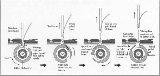
How a sewing machine works.
- 4 Gears are made of injection-molded synthetics or may be specially tooled to suit the machine.
- 5 Drive shafts made of metal are hardened, ground, and tested for accuracy; some parts are plated with metals and alloys for specific uses or to provide suitable surfaces.
- 6 The presser feet are made for particular sewing applications and can be interchangeable on the machine. Appropriate grooves, bevels, and holes are machined into the feet for their application. The finished presser foot is hand polished and plated with nickel.
- 7 The frame for the home sewing machine / is made of injection-molded aluminum. High-speed cutting tools equipped with ceramic, carbide, or diamond-edged blades are used to drill holes and to mill cuts and recesses to house features of the machine.
- 8 Covers for the machines are manufactured from high-impact synthetics. They are also precision-molded to fit around and protect the machine's components. Small, single parts are preassembled into modules, whenever possible.
- 9 The electronic circuit boards that control the machine's many operations are produced by high-speed robotics; they are then subjected to a burn-in period that is several hours long and are tested individually before being assembled in the machines.
- 10 All of the parts that are preassembled I; join a main assembly line. Robots move the frames from operation to operation, and teams of assemblers fit the modules and components into the machine until it is complete. The assembly teams take pride in their product and are responsible for purchasing the components, assembling them, and making quality control checks until the machines are completed. As a final quality check, every machine is tested for safety and various sewing procedures.
- 11 The home sewing machines are sent to packing where they are separately assembled by power control units that are foot-operated. A variety of accessories and instruction manuals are packed with the individual machines. The packaged products are shipped to local distribution centers.
Quality Control
The quality control department inspects all raw materials and all components furnished by suppliers when they arrive at the factory. These items are matched with plans and specifications. The parts are again checked along every step of manufacture by the makers, receivers, or persons who add the components along the assembly line. Independent quality control inspectors examine the product at various stages of assembly and when it is finished.Byproducts/Waste
No byproducts result from sewing machine manufacture, although a number of specialized machines or models may be produced at one plant. Waste is also minimized. Steel, brass, and other metals are salvaged and melted down for precision castings whenever possible. Remaining metal waste is sold to a salvage dealer.The Future
The merging of the capabilities of the electronic sewing machine and the software industry is creating an ever-widening range of creative features for this versatile machine. Efforts have been made to develop threadless machines that inject thermal fluids that harden with heat to finish seams, but these may fall outside the definition of "sewing." Large embroideries can be machine-produced based on designs developed onscreen using AUTOCAD or other design software. The software allows the designer to shrink, enlarge, rotate, mirror designs, and select colors and types of stitches that can then be embroidered on materials ranging from satin to leather to make products like baseball caps and jackets. The speed of the process lets products celebrating today's victories hit the street by tomorrow's business day. Because such features are add-ons, the home sewer can buy a basic home sewing machine and enhance it over the years with only those features most frequently used or of interest. Sewing machines become individual crafting devices and, therefore, seem to have a future as promising as the imagination of the operator.Industrial Automation
When you combine the innovations of motion control, the Internet of Things, 3D printing, electronics and sensors, and mechanical components, you get the latest drivers in industrial automation. Industrial automation covers the ongoing developments of how engineers automate every aspect of our world.

Controlling the Coating Process with Robotics
Robots can be programmed to coat almost any part shape, no matter how complex, at any speed needed for efficient processing.
Applying a coating to a medical device or instrument can improve the device’s performance and reduce potential side effects. As recent history shows, selecting the right coating material and controlling coating processes in ways that are reproducible can be challenging and fraught with obstacles. Flaking, lifting, or delamination of the coatings, as well as inconsistent and non-uniform coatings on a device surface, are potential failure modes that can result in recalls and risks to patient safety. The solution is developing and validating a uniform and repeatable process and then putting the controls in place to monitor and ensure the processes are consistently executed.
Meeting Specifications
Today’s coating specifications on medical devices often call for high precision with tight tolerances of micron-thin films. These coatings must be applied at controlled thicknesses and coverages, which requires them to be metered and measured to exactness. However, accurately controlling the distribution of the coating to three-dimensional surfaces or ultra-small surfaces can be very complex.

Advertising, Mouse Over for Audio
Conventional coating systems and processes are often incapable of this level of control and uniformity. Robotic coating systems, on the other hand, are the “gold standard” in coating control, repeatability, and process efficiency. The robot is the “driver” of the system, capable of repeating a specific process, consistently delivering the exact amount of material to a part surface, while controlling all the process parameters. Robots can be programmed to coat almost any part shape, no matter how complex, at any speed needed for efficient processing.
Developing and validating a uniform coating process involves three daunting tasks:
(1) selecting the right coating material for the application,
(2) specifying and testing the application parameters needed to deliver the coating specifications, and
(3) designing the coating system; production equipment, throughput requirements, process parameters and controls to ensure the repeatability of the coating process.
These steps become what is known as the “Coating Recipe.” Each recipe is specifically created for the customer’s unique application and requirements.
Once the Coating Recipe is optimized, tested, and validated, it then can be programmed into the robot to deliver the exact metered and mixed material, at a set film thickness, to correct locations on the part’s surface with little variation. Any change, small or large, in any variable or parameter can affect coating results.

Electrostatic atomizer used in a total coating system.
Selecting the Right Coating Material
Achieving the coating specifications and results starts with selecting the right coating material. A critical part of the selection process is understanding the properties, formulations, and characteristics of the coating materials, and how each behaves with the application process.
Most coatings are formulated as powder or liquid dispersions. Liquid dispersions are either water-based (aqueous) or solvent-based. When applying liquid dispersions, viscosity, flow properties, and particle size are critical factors for film build and uniformity. Viscosity and other properties may need to be adjusted for certain application processes (dip vs. spray), or to account for manufacturing environmental changes such as humidity or temperature. Other important material properties that need to be considered include shear sensitivity, flash points, melt points, volatility, conductivity, resistivity, wetting and flow characteristics, surfactants and pigments, particle size, and curing temperatures and times—plus regulatory and environmental issues.

XXX . V000 Assembly line industrial engineering
Assembly line, industrial arrangement of machines, equipment, and workers for continuous flow of workpieces in mass-production operations.
 Robotic welding on the automobile assembly line at the Toyota Motor Corporation, Japan.Courtesy, Toyota Motor Corporation
The design for an assembly line is determined by analyzing the steps necessary to manufacture each product component as well as the final product. All movement of material is simplified, with no cross flow, backtracking, or repetitious procedure. Work assignments, numbers of machines, and production rates are programmed so that all operations along the line are compatible.
An automotive assembly line starts with a bare chassis. Components are attached successively as the growing assemblage moves along a conveyor. Parts are matched into subassemblies on feeder lines that intersect the main line to deliver exterior and interior parts, engines, and other assemblies. As the units move by, each worker along the line performs a specific task, and every part and tool is delivered to its point of use in synchronization with the line. A number of different assemblies are on the line simultaneously, but an intricate system of scheduling and control ensures that the appropriate body type and colour, trim, engine, and optional equipment arrive together to make the desired combinations.
Automated assembly lines consist entirely of machines run by machines, with little or no human supervision. In such continuous-process industries as petroleum refining and chemical manufacture and in many modern automobile-engine plants, assembly lines are completely mechanized and consist almost entirely of automatic, self-regulating equipment.
Many products, however, are still assembled by hand because many component parts are not easily handled by machines. Expensive and somewhat inflexible, automatic assembly machines are economical only if they produce a high level of output. However, the development of versatile machinery and the increased use of industrial robots have improved the efficiency of fully automated assembly operations.
Though prototypes of the assembly line can be traced to antiquity, the true ancestor of this industrial technique could be found in the 19th-century meat-processing industry in Cincinnati, Ohio, and in Chicago, where overhead trolleys conveyed carcasses from worker to worker. When these trolleys were connected with chains and power was used to move the carcasses past the workers at a steady pace, they formed a true assembly line (or, in effect, a “disassembly” line in the case of meat cutting). Stationary workers concentrated on one task and performed it at a pace dictated by the machine, thereby minimizing unnecessary movement and dramatically increasing productivity.
Drawing upon examples from the meatpacking industry, the American automobile manufacturer Henry Ford designed an assembly line that began operation in 1913. This innovation reduced manufacturing time for magneto flywheels from 20 minutes to 5 minutes. Ford next applied the technique to chassis assembly. Under the old system, by which parts were carried to a stationary assembly point, 12 1/2 man-hours were required for each chassis. Using a rope to pull the chassis past stockpiles of components, Ford cut labour time to 6 man-hours. With improvements—a chain drive to power assembly-line movement, stationary locations for the workmen, and workstations designed for convenience and comfort—chassis assembly time fell to 93 man-minutes by the end of April 1914. Ford’s methods drastically reduced the price of a private automobile, bringing it within the reach of the growing middle class in the United States.
Ford’s accomplishments forced both his competitors and his parts suppliers to imitate his technique. As the assembly line spread through American industry, it brought dramatic productivity gains but also caused skilled workers to be replaced with low-cost unskilled labour. The pace of the assembly line was dictated by machines, meaning that plant owners were tempted to accelerate the machines, forcing the workers to keep up. Such speedups became a serious point of contention between labour and management. Furthermore, the dull, repetitive nature of many assembly-line jobs bored employees, reducing their output.
Effects on the organization of work
 Learn about the job specialties involved in planning and completing a building construction …© The University of Newcastle, Faculty of Engineering and Built Environment with thanks to Jeremy Ley and Nick Parker from Light Creative (A Britannica Publishing Partner)
Mass production also heightened the trend toward an international division of labour. The large scale of the new factories often made it economical to import raw materials from one country and produce them in another. At the same time, the saturation of domestic markets led to a search for customers overseas. Thus, some countries became exporters of raw materials and importers of finished goods, while others did the reverse. In the 1950s and ’60s some predominantly agricultural countries (particularly in Asia and South America) began to manufacture goods. Because of the low skill levels required for assembly-line tasks, residents of any background could work in the new manufacturing sector. Standards of living in developing countries were so low that wages could be kept below those of the industrialized countries. This made the entire production process less expensive. Many large manufacturers in the United States and elsewhere therefore began outsourcing—that is, having parts made or whole products assembled in developing countries. Consequently, developments in these countries have changed the face of the world economic community.
XXX . 5 Examples of How the Industrial Internet of Things is Changing Manufacturing

Peter Gutzmer, deputy CEO and CTO at Schaeffler sees a smart, connected future as the essence of Industry 4.0.
"We are entering an age where parts can monitor and evaluate their own performance and even order their own replacement when necessary,” said Gutzmer. “Schaeffler is a world leader in product development and manufacturing, IBM in hybrid cloud and cognitive computing; through this partnership we are ushering the new industrial era."
More specifically, Schaeffler’s first phase of integration with IBM’s IIoT solutions involve five areas of focus.
1) Optimizing Maintenance in Wind Energy
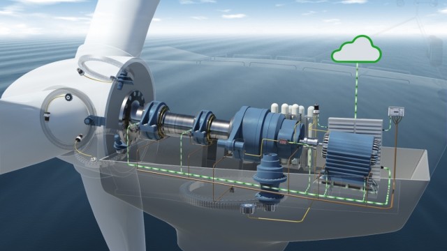
Using sensors in vital components enables users to retrieve information on the condition of wind turbines during operation and process it in real time. (Image courtesy of Schaeffler.)
2) Digitized Monitoring and Optimization of Trains
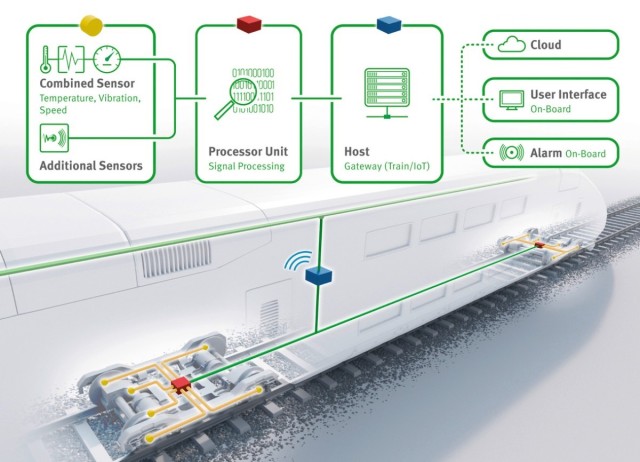
Monitoring systems with local software and cloud-based analytics in trains improves their operational safety and reduces operating costs. (Image courtesy of Schaeffler.)
3) Connected Vehicles

Real time analytics and cognitive systems will turn data from components and systems into valuable insights. (Image courtesy of Schaeffler.)
4) Industry 4.0 for Machine Tools
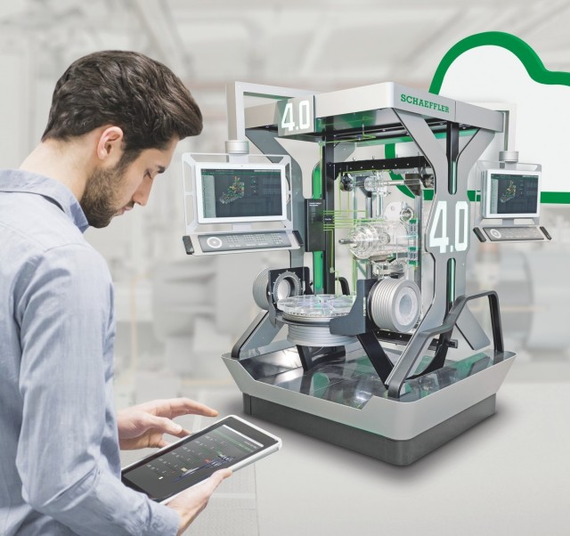
Schaeffler’s digital platform technologies are being used for machine tools to systematically improve overall equipment efficiency. (Image courtesy of Schaeffler.)
5) Connected Equipment Operations Centers

(Image courtesy of Schaeffler.)
"This is an era of unprecedented industrial transformation defined by factories, machines and parts capable of self-assessing, triggering actions and exchanging information with each other, and with the people who manufacture and maintain them," said Harriet Green, general manager of IBM Watson IoT. "Schaeffler is leading the way and literally redefining approaches for designing, producing and maintaining machines–making them safer and more reliable."
Electronics
As electronics is now incorporated into virtually every sector of the economy, it offers a wide range of job possibilities. Some of these occupations are focused on assembling, testing, repairing and inspecting consumer, and industrial equipment and other electrical products and systems. Others involve designing, developing and testing the production and operation of electrical and electronic equipment and systems. Everything from satellite systems to ski lift controls requires workers with training in electronics.
Specific tasks that electronic technologists and engineers may perform include linking computer networks to hydraulic systems, establishing communication links to remote locations or designing and retrofitting electrical systems. Technicians are involved in the installation, set-up and repair of these same types of systems. Depending on their area of expertise, people in electronics need to know and understand many different electronic concepts with background in the applied sciences. As technology continues to grow and evolve everything could one day be electronically based, which makes electronics an occupation of the future.
Main duties
Electronics assemblers perform some or all of the following duties:- Solder and manually assemble various electronic components such as resistors, diodes, transistors, capacitors, integrated circuits, switches, wires and other electronic parts to designated locations on printed circuit boards
- Assemble microcircuits requiring fine hand assembly, the use of microscopes and adherence to cleanroom procedures
- Install, mount, fasten, align and adjust parts, components, wiring and harnesses to subassemblies and assemblies using hand and small power tools
- Operate automatic and semi-automatic machines to position, solder and clean prescribed components on printed circuit boards
- May replace defective components and repair and overhaul older devices.
Electronics assemblers perform some or all of the following duties:
- Solder and manually assemble various electronic components such as resistors, diodes, transistors, capacitors, integrated circuits, switches, wires and other electronic parts to designated locations on printed circuit boards
- Assemble microcircuits requiring fine hand assembly, the use of microscopes and adherence to cleanroom procedures
- Install, mount, fasten, align and adjust parts, components, wiring and harnesses to subassemblies and assemblies using hand and small power tools
- Operate automatic and semi-automatic machines to position, solder and clean prescribed components on printed circuit boards
- May replace defective components and repair and overhaul older devices.
Electronics fabricators perform some or all of the following duties:
- Operate and monitor process equipment including automatic and semi-automatic machines to fabricate electronic components, solder, clean, seal and stamp components and perform other process operations as specified
- Set up process equipment and adhere to cleanroom procedures as required.
Electronics inspectors perform some or all of the following duties:
- Inspect electronic components and assemblies to ensure correct component selection and placement, wiring and soldering quality, proper pin insertions, location and diameter of plated holes, breaks in circuitry and line spacing in printed circuit board and other specified requirements while products are being assembled or fabricated
- Check final assembly for finish, labelling and packaging methods
- Check mechanical dimensions and perform "go-no-go" electrical tests
- Identify and mark acceptable and defective assemblies and return faulty assemblies to production for repair
- Collect, record and summarize inspection results
- Investigate equipment malfunction and instruct on proper operation.
Who do they work for?
- Commercial companies
- Government utilities
- Consulting engineering firms
- Educational institutions
- Resource based industries
- High technology design
- Manufacturing
- Communication companies
- Self-employed
XXX . V000 Robotics in Electronics
The electronics and semiconductor industry has emerged as an important sector for robotics. While automotive applications still constitute the lion’s share of robotics, the volume of robots sales to the electronics and semiconductor industry shot up by nearly two-thirds during the first quarter of 2011, according to data compiled by the Robotic Industries Association. (RIA, Ann Arbor, Michigan)
“The ease of use of robotics for electronics and semiconductors has increased tremendously which has subsequently reduced installation times and total cost of implementing robotic solutions,” says Rush LaSelle, Director of Global Sales and Marketing with Adept Technology Inc. (Pleasanton, California) LaSelle and his peers in the robotics industry see more powerful yet less expensive robots proliferating for production of semiconductors and electronics.
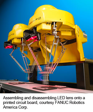
Speed, Accuracy, PrecisionIn most industrial applications, robots facilitate high throughput although parts manipulated in those applications are usually less fragile than those found in the electronics and semiconductor sector. “Components are much smaller than in typical industrial robotic applications, requiring higher precision gripper designs. Because process speeds are usually quite fast, grippers need to handle higher inertia,” professes Christopher Blanchette, FANUC Robotics America Corp.’s (Rochester Hills, Michigan) National Account Manager. “Accuracy is an important element in the electronics industry because the parts are much smaller. Precision of locating, placing and assembling parts is critical.”
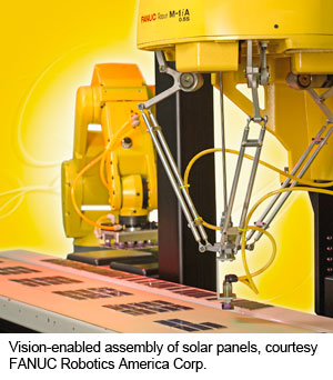
Robot manufacturers and peripheral equipment providers developed tools such as vision to support the accuracy requirements in the electronics industry, adds Blanchette. Continuing, Blanchette says adaptive robotics is a necessity in the electronics and semiconductor industry. “Robots pick up and place components into electronic assemblies where the position is not always precisely known or parts cannot be reliably placed without finessing. Adaptive tools such as vision or force control allow the robot to ‘feel’ its way into an assembly, placing parts in a dynamic assembly process.”
 Precision is also on the mind of Henry Loos, Controls and Application Engineer with Applied Robotics Inc. (Glenville, New York), who says, “Precision is the primary challenge in electronics and semiconductor applications. Tolerances in electronics assembly are much tighter than other processes such as automotive manufacturing.” The necessity for precision is complicated by the requirement for very high production rates, contends Loos.
Accuracy is the biggest challenge in semiconductor applications, says Kirk Barker, Electronics Product Manager at Maxon Precision Motors Inc. (Fall River, Massachusetts) “Accuracy of a control system is ultimately determined by the quality and amount of information provided by feedback devices and sensors. In semiconductor applications, accuracy is the number one consideration given the importance placed on yield.” Barker sees six areas where end-users and integrators should focus on to improve robotic utility in manufacturing: range of motion and dexterity, reach, accuracy, speed, force compliance and safety.
Speed for the sake of speed is insufficient in semiconductor and electronic applications, points out LaSelle. “In handling semiconductors, the robot must not only be fast but must gently handle wafers to avoid introducing micro-cracks or physically damaging the very thin products.” As semiconductor wafers become thinner, 150 microns or less, LaSelle sees increased damage caused by direct human labor. “The propensity for damage is greatest when labor is applied. As wafer thicknesses decrease over time as forecasted, thermal expansion of the silicon will become an issue during soldering.”
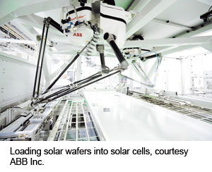
LaSelle goes on to say, “Unlike traditional semiconductor industry pursuits, alternative energy manufacturing processes are early in their life-cycle and subject to processing change.” Robotics lends themselves to high output, improved yield and the ability to adapt to process changes in the solar panel fabrication industry, portrays LaSelle.
CleanroomsMany processes within electronics and semiconductor applications demand cleanroom operations. “The trend in robotics for the electronics industry is cleaner robots in a smaller footprint and smaller controllers using less power,” says Joseph Campbell, Vice President of ABB Inc.’s (Auburn Hills, Michigan) Robot Products Group. Campbell’s colleague at ABB, Robot Product Support Group Manager Nicholas Hunt observes, “Cleanroom is a whole environmental process, not just the robot. Robots moving at high speeds shed more particles.” Designing fast-moving robots that maintain their cleanroom certification is a challenge, conveys Hunt.
To maintain cleanroom certification, a robot needs integration within a sterile environment, explains Blanchette. “Cleanroom requirements are very stringent for semiconductor manufacturing. Robots for semiconductor manufacturing need special packaging and delivery into a cleanroom environment so they do not pick up particulate while in transit. The most significant challenge is integrating the robot system within a special cleanroom environment.”
Cleanroom robots are shipped within a protective bag but if that bag is removed on a standard factory floor at the integration site, the robot no longer carries its cleanroom certification. “The robot must go through a cleansing process to become cleanroom certified again,” Blanchette says.
Henry Loos notes that integrators must consider the affect all equipment has on a cleanroom environment, not just the robot. “Operating within a cleanroom does not typically impact the robot. Minimizing the robot’s impact on the cleanroom is a greater challenge.” These challenges are met by employing coatings and lubricants that minimize the potential for contamination caused by robots in clean areas, posits Loos.
LaSelle also says integrators ought to carefully choose equipment going into a semiconductor work cell. “This market segment demands careful consideration of components used to develop a highly robust manufacturing process. The manner in which components are integrated significantly impacts the ultimate cleanliness of the cell. In cleanroom applications, the process of deployment is as important as the hardware itself.”
LaSelle adds, “Robotics affords high throughput, improved yield with the ability to adapt to changes in process equipment.” To maintain yields during assembly tasks and soldering operations, even in low cost labor markets, semiconductor and electronics manufacturers are increasingly turning to robotics, LaSelle says.
Robot manufacturers deliver standard and custom cleanroom robot solutions tailored to the semiconductor or electronics industries’ requirements by investing time and resources prior to the design of systems, applying lessons-learned through experience in cleanroom applications, says LaSelle.
Machines of ChoiceUntil relatively recently, selective compliance assembly robot arm (SCARA) machines were the robots of choice for fabrication of electronics and semiconductors. “Some electronics and semiconductor manufacturers still use SCARA or cartesian robots, but many see a requirement for articulated and delta robots. Smaller robots, typically, deltas and small serial-link robots, are used for electronic assembly,” says Blanchette.
Similarly, Loos sees the rise of delta robots working along with SCARAs and six-axis articulated robots in the semiconductor and electronics sector. “SCARAs and deltas are at the forefront in the assembly process because of low inertia and high precision at high speeds. With vast improvements in the accuracy and speed of six-axis robots, expect to see them fulfilling both handling and assembly roles.”
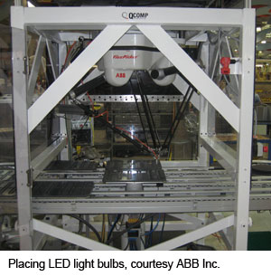
ABB’s Campbell and Hunt consider delta robots ideal for semiconductor and electronics applications. “Delta robots have historically been used in picking and packing applications, mostly in the consumer goods and food sectors. Recently, we see more interest in delta robots in assembly applications for electronic components,” relates Campbell. “Circuit board assembly can be done with small Cartesian or SCARAs, although deltas are used for assembly of electrical components and tying solar panels together in photovoltaic applications.”
Hunt says delta robots provide value for electronic and semiconductor assembly due to their inherent accuracy and repeatability. “The accuracy and repeatability of delta style robots are high enough to be of merit in the electronics industry, particularly in solar applications for picking and placing individual photovoltaic cells for panel assembly over a large work envelope.”
LaSelle believes a multitude of robot configurations are suited for the electronics and semiconductor industry. “SCARAs offer a cylindrical work envelope and typically provides higher speeds for picking, placing, and handling processes compared to Cartesian and articulated robots. SCARA deliver greater repeatability and positional capabilities superior to articulated arms,” says LaSelle. SCARAs are used for payloads under 10 kilograms in assembly, packaging, and material handling applications, concludes LaSelle.
Multi Apps
End-users want their equipment to perform a myriad of tasks, leading them towards flexible robotics. When feasible, robots in the semiconductor and electronics industry combine assembly, dispensing, machine tending, material handling, material removal and packaging applications. “Robots are used in many processes in electronic and semiconductor manufacturing including assembly and dispensing. Military components require more shock and environmental shielding,” says Blanchette. Military electronics and semiconductors go through more sealing and encapsulation processes than typical consumer electronics so the robot will perform those dispensing applications as part of the assembly process, Blanchette opines.
Combining assembly with dispensing is common, says Henry Loos. “Electronics manufacturing is heavy on assembly but other processes are included as well. Housing sealants, adhesives, and board component vibration protection require dispensing. Machine tending is needed in most high speed machining applications, and assembly operations require a great deal of material handling.”
Robots are also performing inspection tasks, says Blanchette. “Many end-users invest in robots to handle parts in inspection work cells, doing error-proofing during assembly. For a very low cost, end-users can validate their process and increase the yield and quality of their components during manufacturing.”
Continuing, Blanchette says, “Machine tending, material handling and packaging applications are common. Electronics assembly requires robotic handling, snapping electronics into a plastic component, putting all elements together into an assembly, and packing it at the end of the assembly line.”
ABB’s Joe Campbell declares, “High-volume production of most electronic devices screams for robotics. End-users have robots doing kitting, case-packing, and palletizing of consumer electronics. The amount of care going into surface finishes on electronic devices is increasing and we see more trimming, polishing, and, buffing applications using force control to get a consistent finish on electronic components.”
Hunt adds, “We see more thermography, robots looking for hot and cold spots on printed circuit boards. Vision is used to locate electronic components and do testing and inspection through non-tactile sensing. Robot controllers track electronic devices as they move through the production line.”
Tool changers augment the ability of robots to multitask in electronics and semiconductor work cells. “Technology offers high levels of asset utilization through faster production change-over times and redeployment of equipment. Robots deliver high value in their ability to multitask and automate numerous functions within a given workspace. A robot can automatically change its tooling or end-effector to satisfy the task at hand,” says LaSelle.
Using an example to illustrate his point, LaSelle says, “The robot uses one tool to pick substrates and place them into a fixture. Once placed, the robot might use another tool to apply adhesive onto mating surfaces on the part and then places assembled components onto a conveyor. The robot might wield all these tools or use a changing device to handle a gripper for picking and placing, exchanging that device, when called upon, to dispense adhesives.”
Robotic E-Assembly
As electronic devices become more sophisticated, the need for a more advanced assembly process naturally follows. That increased level of sophistication is a perfect fit for robotics. “The proliferation of sensory input such as vision has created intelligent robotic solutions. In the past, elaborate and expensive fixtures were required to get electronic components and sub-assemblies into a precise location for a robot to pick, manipulate, assemble, then package a part. The same accuracies are achieved using basic in-feeds and vision,” LaSelle postulates.
XXX . V00000 The digital industrial revolution

For companies looking to maximise the immense opportunities associated with Industry 4.0 there are also many different challenges associated with delivering this digital transformation.
As complex networks are created the convergence of enterprise IT and operational technology (OT) will accelerate as new IoT devices and greater automation technologies are introduced.
While standardised interfaces and state-of-the-art information technology will permit highly flexible, automated ‘plug and produce’ manufacturing as each new device is added to the production process, most will bring with them their own set of proprietary interfaces. As a result, facilitating effective interoperability across the entire manufacturing process will be no easy task.
Earlier this year the consultants, Capgemini, announced the findings of its Smart Factories report for 2017. It reported that manufacturers were expecting their investments in smart factories to drive a 27% increase in manufacturing efficiency, which could be worth an additional $500 billion to the world’s economy over the next five years.
As defined by Capgemini the term “smart factory” looks to cover technologies such as artificial intelligence (AI), advanced robotics, IoT and big data analytics. The smart factory looks set to include collaborative robots, augmented reality and predictive maintenance.
Among those sectors leading in the adoption of these technologies are aerospace, defence, industrial manufacturing and automotive, and in the UK the survey found that 70 percent of manufacturers were looking to use smart factories. The survey found that within the next five years 27% of UK manufacturers said that they were looking to produce their products in smart factories, while 48% said they were looking to establish a network of smart factories.
According to Peter Hannon, UK Managing Director, Harting, the ultimate goal for manufacturers adopting, or looking to adopt, Industry 4.0 or smart factory solutions is to be able to deliver customisable products, increasing quality and reducing manufacturing costs.
“These goals can only be achieved by creating a digital system that is able to gather data and then reports back information on manufacturing processes such as workflow, energy use and faults,” Hannon explains.
“This raw data will be analysed and transformed to provide meaningful insights about the manufacturing process, or a particular piece of machinery, with a view to organising maintenance schedules, implementing automation, managing energy use and contributing to future improvements and savings.”
Increased visibility at all stages of the production process will enable manufacturers to take a proactive view of activities such as maintenance and production flow, while the inclusion of real-time data means that decisions can be based on the current “live” situation rather than just historical data.While standardised interfaces and state-of-the-art information technology will permit highly flexible, automated ‘plug and produce’ manufacturing as each new device is added to the production process, most will bring with them their own set of proprietary interfaces. As a result, facilitating effective interoperability across the entire manufacturing process will be no easy task.
Earlier this year the consultants, Capgemini, announced the findings of its Smart Factories report for 2017. It reported that manufacturers were expecting their investments in smart factories to drive a 27% increase in manufacturing efficiency, which could be worth an additional $500 billion to the world’s economy over the next five years.
As defined by Capgemini the term “smart factory” looks to cover technologies such as artificial intelligence (AI), advanced robotics, IoT and big data analytics. The smart factory looks set to include collaborative robots, augmented reality and predictive maintenance.
Among those sectors leading in the adoption of these technologies are aerospace, defence, industrial manufacturing and automotive, and in the UK the survey found that 70 percent of manufacturers were looking to use smart factories. The survey found that within the next five years 27% of UK manufacturers said that they were looking to produce their products in smart factories, while 48% said they were looking to establish a network of smart factories.
According to Peter Hannon, UK Managing Director, Harting, the ultimate goal for manufacturers adopting, or looking to adopt, Industry 4.0 or smart factory solutions is to be able to deliver customisable products, increasing quality and reducing manufacturing costs.
“These goals can only be achieved by creating a digital system that is able to gather data and then reports back information on manufacturing processes such as workflow, energy use and faults,” Hannon explains.
“This raw data will be analysed and transformed to provide meaningful insights about the manufacturing process, or a particular piece of machinery, with a view to organising maintenance schedules, implementing automation, managing energy use and contributing to future improvements and savings.”
“Industry 4.0 solutions will grant manufacturers much greater flexibility with the use of modular systems that are easily customisable. This means that a manufacturing site will be able to react to market demands and adjust its manufacturing processes and capabilities quickly and cost-effectively,” he contends.
According to Hannon Industry 4.0 comprises of four key elements, “These are: digitalisation, modularisation, miniaturisation and customisation.”
Covering both processes and machinery, digitalisation includes the use of embedded industrial computers and intelligent devices such as sensors to provide data on the machines and processes.
The modularisation of products, factories and processes on the production line is at the heart of the smart factory. Each section can be contained and accessed individually, with modular computers allowing data to be saved, evaluated and then processed at the edge of the machinery.
The miniaturisation, especially where there are high connectivity requirements in areas such as Industrial Ethernet and the Industrial Internet of Things (IIoT), means saving space within the factory infrastructure and the use of next-generation components will enable the faster speeds associated with Industry 4.0.
Finally, customisation across the factory allows the production environment to meet individual users’ requirements and to improve the processes within the factory.
“As well as the benefits customisation offers to manufacturers, it also enables customers to get the most out of the end-product by tailoring it to their specific needs, along with individually customised reports and remote access to production data,” Hannon says.
Modularity
“At the core of the smart factory is the communication between machines, which enables interaction and integration across the whole factory,” explains Gavin Stoppel, Product Manager, Harting.
“Power, signal and data are the three industry ‘lifelines’ on which all manufacturers depend. While links to these specific lifelines can be incorporated directly into the machine, it is also possible to add flexible modular interfaces to transfer data throughout all the levels of the factory.”
Stoppel continues, ”Such devices communicate information and data at all levels, allowing modular production systems to be implemented to provide flexible, cost-effective and innovative production solutions.”
While the Internet provides a platform for direct, interactive, dialogue-centred communication, with network structures replacing the previously used linear design, the cost of deploying a fully integrated system remains a barrier to its widespread adoption.
One solution is retrofitting, according to Stoppel.
“Modular computing forms the basis of a new industrial computer system, MICA (for Modular Industry Computing Architecture), which has been designed to provide existing machinery and systems with intelligence, making it possible to transform existing manufacturing plants into smart factories and bringing to life the potential of integrated industry,” says Stoppel.
“As a result, customers can design their production facilities to be more modular, affordable and less complex. MICA makes it possible to temporarily save, evaluate and process data directly within the machinery and equipment. Based on a modular open platform, it can be customised as required, including the hardware, software and interfaces,” he explains.
MICA functions as a small, robust computing unit between physical devices and a higher-level IT system. It provides a cost-effective solution that allows users to run computing power at all levels as well as communicating with central IT systems and the cloud, offering fast data analysis and decision-making at the field level along with storage and data-collection capability to provide relief for computer centres.
MICA’s open source approach allows users to completely customise the computer: for example, by choosing the programming language and development environment.
 The Harting IIC MICA modular computer
The MICA computer features a powerful 1 GHz ARM processor, 1 Gbyte of RAM and 4 Gbyte of eMMC flash memory (plus an additional 32 Gbyte on a micro-SD card).
The unique identification of plant modules and products is required for production processes to run comprehensively. Real-time production can be viewed via the implementation of RFID (radio frequency identification) systems, along with sensor information for production and maintenance processes.
“This can be used to communicate information about each modular section, and record information for maintenance purposes on writable tags. Identification within the smart factory sees full traceability with continual feedback,” Stoppel explains.
Smart factories have benefited from the concepts surrounding “big data” and properly used, big data will allow machinery and systems to learn and adapt their processes.
Similarly, asset management using a networked environment will enable machines to provide information on their condition and productivity. The resultant data makes it possible to forecast their future operational status and optimise processes which, in turn, assists planning for the requirements of production environment changes and future projects such as new product launches, product modifications or quantity changes.
Whether investing in new systems of looking to retrofit existing systems more manufacturers are beginning to experience the benefits associated with the smart factory.
XXX . V000000 Electronics Engineering Technology
Electronics Engineering Technology
The Electronics Engineering Technology prepares individuals to become technicians who design, build, install, test, troubleshoot, repair, and modify developmental and production electronic components, equipment, and systems such as industrial/computer controls, manufacturing systems, communication systems, and power electronic systems.
A broad-based core : including basic electricity, solid-state fundamentals, digital concepts, and microprocessors, ensures the student will develop the skills necessary to perform entry-level tasks. Emphasis is placed on developing the student’s ability to analyze and troubleshoot electronic systems. its should qualify for engineering assistants or electronic technicians with job titles such as electronics engineering technician, field service technician, maintenance technician, electronic tester, electronic systems integrator, bench technician, and production control technician.
Electronics technicians are in demand in the fields of electronics, instrumentation, communications, computer technology, and telecommunications. Rapid growth continues as consumer, medical, industrial, and military systems rely on advanced technology.
Hot electrons generate light in chips

A metamaterial developed by researchers at King’s College London uses quantum effects to turn electrons flowing through a circuit into ‘hot electrons’ and light in a highly controlled manner. According to the team, this has potential application in optoelectronics and sensing.
The nanomaterial takes advantage of electron tunnelling to produce streams of particles which can have important applications, when properly controlled.
Researcher Dr Pan Wang said: “This one tiny device offers several amazing applications: plasmon excitation, light generation and chemical reaction activation. And all this is achieved by a small, easy to produce material which only requires a small voltage to function.”
A voltage applied across the device causes electrons to flow from one material (eutectic gallium indium) to another (gold nanorods). These are separated by an air gap, which would usually stop the electron flow, but because the air gap is less than 1nm, the electrons can ‘tunnel’ through.
Most of the tunnelling electrons arrive at the gold nanorod tips in the form of ‘hot electrons’, but a small proportion excite plasmons in the metamaterial to emit light whose wavelength is directly related to the applied voltage.
According to the team, this conversion is usually inefficient, but the use of array gold nanorods provides 100billion tunnel junctions, improving electron-to-plasmon conversion and making the emitted light visible.
While there are applications in sensing, the researchers point to a benefit in small scale electronics. Since light is generated by applying a voltage along a 10nm thick nanorod, it can be used to transmit information optically between or within chips. The metamaterial allows optical signals to be produced within a much smaller device, holding the potential of faster electronics.
Triac and quadrac design innovations can simplify LED lighting control
 Figure 1. Q6008LH1LED and Q6012LH1LED Series alternistor triacs and Q6008LTH1LED and Q6012LTH1LED Series quadrac thyristor power control devices from Littelfuse can simplify the process of designing LED lighting controls.
Triacs are at the heart of dimming controls for LED lighting. Triacs used in dimmers have normally been characterised and specified for incandescent lamp loads, which have high current ratings for both steady-state conditions and initial high in-rush currents, as well as very high end-of-life surge current when a filament ruptures.
LEDs have much lower steady-state current than incandescents, and their initial turn-on current can be much higher for a few microseconds of each half-cycle of AC line voltage. Therefore, a spike of current can be seen at the beginning of each AC half-cycle. Typically, the current spike for an AC replacement lamp is 6 to 8A peak; the steady-state follow current is less than 100mA. An LED flood lamp for a recessed ceiling fixture designed to replace a typical filament unit that produces 750 lumens consumes only 13W in contrast with the old filament unit, which normally draws 65W.
Designing an AC circuit for controlling LED light output is very simple when using the newest triac designs, such as the Littelfuse Q6008LH1LED or Q6012LH1LED Series, because the only components required are a firing/triggering capacitor, a potentiometer, and a voltage breakover triggering device. Two inverse parallel sensitive gate silicon-controlled rectifiers (SCRs), such as the Littelfuse S4X8ES1, can be used as the voltage breakover triggering device, allowing the controlling circuit to produce a wide range of light level outputs. Also, using these components as the triggering device allows achieving a low hysteresis control because two SCRs form a full breakback trigger.
If the application doesn’t demand a wide control range and low hysteresis, a simple variable light control may be designed using quadrac devices, such as the Littelfuse Q6008LTH1LED or Q6012LTH1LED Series (Figure 1). (A quadrac device is a special type of thyristor that combines a diac and a triac in a single package.) The circuit shown in Figure 2 minimises the component count by combining the diac triggering device and an alternistor triac in a single TO- 220 isolated mounting tab package. This control circuit allows a little lower full turn-on voltage due to higher VBO switching of the diac trigger device but offers a light dimming function that operates from 175° to <90° of each AC half-cycle.
XXX . V000000 The Principles and Process of Electronic Component Selection
Component Selection: "an art" for SMART and Cost-effective Designs
Electronics components are the major part of the electronics system design and are rapidly undergoing technology advancements both, in performances and sizes. Obviously, the successful companies and products have utilized 'smarter' components in their designs. The method of choosing such "smart" components thus becomes "an art" to be acquired by the engineers today.
It appears as if the process of component selection for the hardware design requirements is very simple and straightforward but indeed there are many considerations and "techniques" involved behind. An error made in the component selection can cause serious damages up to an extent of thrashing and disqualifying the entire design and the product. So, utmost care and precautions are advisable while performing this activity. Hence in most of the organisations, a dedicated team of component engineers are formed to help the design teams. The component engineers need to have the breadth of knowledge and experience in the fundamental understanding of components, their specifications, constructions, and functionalities.
The component engineer is the one who is approached for the selection of components and suppliers since he acts as the liaison between sourcing/supply chain, design and, manufacturing teams as well as strengthens the supplier relationship. Choosing the right component is the most important task involved in the product development cycle because a wrong selection here creates heavy and unpredictable losses (money, machine, men, time, etc.,) throughout the development activities causing failures and delays in the product releases.
Even though the technology advancements, e-commerce and globalisation have made the engineer's life easier, the human interference and intelligence are still very much essential in one or the other form. Utilizing the web-based parametric tables and other user-friendly methods to select a component is easy but one should know how, when and where to use them appropriately. There are reference component databases available in the market, both free and subscription-based. However, these databases may take the engineer to the nearest set-of-components but choosing the best one that suits the design is still the selector's task. There are various parameters such as electrical, mechanical, environmental, cost, reliability factor, availability (life cycle), etc., which should, at a minimum, be considered while selecting a component.
Component selection is a process of selecting a suitable component or a set of similar components from different suppliers for the designed circuit to perform its intended operation. The component engineer may have to first understand the circuit functionality or has to get the exact parametric values with the permissible tolerance levels for each parameter from the design engineer. The component engineer has to volunteer in gathering as many details as possible from the design engineer in order to speed up the component selection. Most of the times, the design engineer invariably provides the list of critical parameters alone, but for the component engineer, the other non-listed parameters are also critical. Hence it's important for the component engineer to query the design team even for a small doubt and not to guess or consider the attribute values for granted.
The component engineer should also consider the "underlying factors" or the "competitive edge" of the component when compared with the nearest competitors. Due consideration should be given to the affordability - a factor that guides the company to prefer an expensive component to avail the additional features, become more competitive and reap the most out of the investment made. Here a line of compromise is drawn and compared between the investment made and the return on the investment while choosing the technology-based competitively-edged components.
Mere choosing the right component is just not sufficient for product development but to track and control every component's specifications throughout the supply chain and the product's life cycle is also significant. Many companies implement part-specific and product-specific specification control documents which are updated as and when a change is made with respect to the part or the product. These changes can be due to external factors such as the component manufacturer releases a product or process change notifications that affect the component's form, fit or function; manufacturer mergers and acquisitions; plant or factory relocations; alternate fabrication sites; etc., and internal factors such as preferring alternate part or supplier or distributor; changes made in the design boards; inclusion/exclusion of circuitry or components; changes in the test parameters; etc., Even the component's end-of-life (EOL) period is tracked in this specification control document. Hence, the traceability factor can help the organisation to mitigate component risks easily and proactively.
The life cycle of the component is yet another attribute that should be focused while selecting a component, its more relevent in case of semiconductor IC chips. The predicted life of all the components inside the product constitutes to the life of the product itself in addition to the other variables. The present 'availability' factor of the component is important, but how long the component is going to be available in the future is much more important. The designs and products end up costly because of their improper selection of components. Selecting a component which is near to end-of-life is an added risk or an overhead to the company and choosing a component which was just invented (just born) is risking with the component's survivability itself. So, wise judgement that promotes the usage of the low-risk, long-life components in the BoMs (bill of materials) should be taken. To mitigate the component's unpredicted risks, one should always maintain a list of alternate components and sources. More details about the component's life cycle management are presented in a separate module. Many organisations invest lot of efforts and money due to component's unavailability and obsolescence issues. "Better be prepared with alternate components' list than to struggle with odd and costly situations".
The next important aspect to consider is the "reliability" of the component which is termed as the chance of the component to perform its planned function for the specified time interval under the defined conditions with a given confidence level. To put it simpler, the reliability of a component is the quality of the component's performance over a period of time. The amount of time period where the failure rate is constant is the useful life period of the component and usually the component's reliability is provided in reliability % or MTBF score or failure rates. The popular three methods of predicting component's reliability are PRISM (217+ method), Telcordia (Bellcore method) and MIL-HDBK-217. The component's reliability helps the design team to verify the design's ability to meet its objectives early in the development stage. Also, the reliability factors helps to calculate the warranty and safety durations as well as perform decisions on design substitutions.
Having understood the generic factors such as component's availability or the life cycle, affordability or the feature-rich expensive selection, traceability or the component's history log and the reliability or the quality of the component's performance over a period of time, let's go through few important technical parameters. Technical parameters, for our understanding, can be classified into electrical, mechanical and environmental.
1. Electrical parameters are the ones which directly dictate the functionality of the component. Each component category has its own primary specifications rated and designed for. There are few specifications which are category-specific and few others are generic in nature. For example, operating temperatures, voltages, etc., are almost applicable for all the component categories and hence are generic in nature. Whereas examples like capacitance value, memory width, cut-off frequency, etc., are applicable to few specific categories only and hence these attributes are category-specific attributes.
The table below is a reference of few categories and their key electrical attributes' list which helps in searching a component in its respective category.
Certain parameters should be given due consideration and these parameters depend upon the end application of the product. The end-application can vary between military, commercial and industrial purposes. Weather withstanding capabilities of commercial grade devcies are not so good as industrial grade and the military grade devices withstand extreme and extended conditions that the military products operate with. The extended temperature ranges, thermal shocks and vibrations, humidity and moisture tests, dampening tests, etc., are few parameters to be considered carefully. Also, there are many manufacturers who qualify their components to military standards and exclusively trade those components as MIL-qualified components. Be-aware of the difference between MIL-qualified and tested as per MIL-standards.
2. Mechanical parameters are the ones which indicate the physical form, mounting styles, size and weight of the component. These parameters can be felt or physical in nature. These features decide how the component connects with other components in the circuit board. See the below list of mechanical attributes list which can be suitably considered while choosing the component.
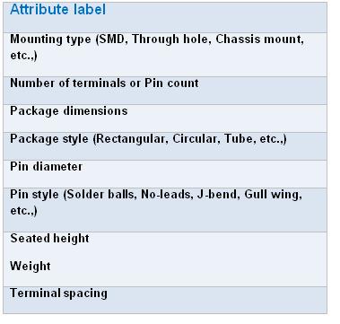
It's very important to have prior information about the physical dimension and mechanical specifications requirements from the design team because almost many suppliers have the same functional component in more than one package styles. The ordering information would definitely vary with the package styles and hence choosing the right package code is vital.
3. Environmental parameters are the ones which are related to the component's behaviour and ratings with respect to the different environmental conditions. Extreme environmental conditions are simulated in the lab for test purposes and that's how the component's ratings are measured. In addition, there are regulatory authorities governing the ban or the restricted use of certain hazardous substances in the components thereby providing instructions to the manufacturers to comply with these regulations in order to perform the business in the specified countries or markets. The list of important environmental attributes is given below.
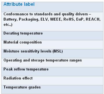
Above all, one should not forget about the new requirements posed by the environmental regulators worldwide. The new regulations may require suitable evidences in the form of IPC-1752 material composition declarations, test reports, RoHS certificates, certificates of conformances (CoCs), custom-declarations, etc., Without these evidences, it's very risky and dangerous to consider or use the related component in the designs and perform business in that particular region or country. However, there are certain exemptions permitted with respect to few substances, their permissible usage and applications in which the selected components get in.
The packaging preference is another parameter to consider in selecting a component. The presence of different manufacturing or board assembly methods and feasibilities necessitates specific flow of components in the production line. The flow of components depends on the type of packaging or shipping method used. Packaging is the method of placing the components in an order which is suitable to be picked up one by one automatically by the computer-controlled machines in the manufacturing or assembly plants. So, components usually are delivered in tape and reel, bulk, ammo packs, tubes, and boxes. Choosing the right packaging method simplifies the assembling or soldering activity.
Of course, there may arise one or the other form of supply chain constraints such as counterfeits, obsolescence, long lead times, minimum order quantities, extra cost for preferred packaging and quantities, logistics and warehouse issues, free samples, lot rejections, damages, sustainability, vendor compliance, etc., during the selection and qualification process. With the help of cross-functions and previously made agreements, these issues can be solved on a need basis and more details are presented in the "Supplier selection" module. Hence, the role of component engineers is so valuable and productive in the supply chain…!
Few important points that can be considered:
1. Try to maintain the company-wide "preferred parts list" (PPL) - a list that contains pre-qualified components list where component and supplier evaluations are conducted and passed. This list should be a controlled database (even an MS-Excel can work as a controlled database) and only designated authority should have editing permissions. Always, give 1st preference to select the components from the PPL for new or existing designs.
2. One should not come to a conclusion or select a component by just glancing through the main description given at the top of the datasheet. Go through the datasheet thoroughly and evaluate for the electrical parameters given by the design team.
3. Make a list of critical components in the designed circuitry and possibly try to conduct piece part reliability predictions and test the samples accordingly.
4. Ensure effective supply chain processes are in place and practised in order to control the redundant and duplicate components dwelling in the inventory.
5. Emphasize to re-use existing component as much as possible - so that intangible benefits can be ripened.
6. Standardize the component descriptions in the component database or the PPL (if maintained) - has the magical ability to deliver so many options for a variety of purposes in the supply chain….!
7. Prefer to select a component from the approved list of manufacturers or suppliers. Practically it's hard to find all the components required for the design from the given list of approved/preferred suppliers. In this case, it's better to perform vendor or supplier qualification and to have a process incorporated to monitor and evaluate the deliveries made by the non-preferred suppliers.
8. Selection of parts should be mature enough to satisfy a wide range of design applications - hard task right…? That's the reason why this writer called it's an art to acquire. And lastly, update your knowledge with the latest trends, technology advancements, industry regulations and dynamism in the market with respect to your field of operation.
===== MA THEREFORE COMPONENENT INDUSTRIAL ELECTRONIC MATIC =====
Designing an AC circuit for controlling LED light output is very simple when using the newest triac designs, such as the Littelfuse Q6008LH1LED or Q6012LH1LED Series, because the only components required are a firing/triggering capacitor, a potentiometer, and a voltage breakover triggering device. Two inverse parallel sensitive gate silicon-controlled rectifiers (SCRs), such as the Littelfuse S4X8ES1, can be used as the voltage breakover triggering device, allowing the controlling circuit to produce a wide range of light level outputs. Also, using these components as the triggering device allows achieving a low hysteresis control because two SCRs form a full breakback trigger.
If the application doesn’t demand a wide control range and low hysteresis, a simple variable light control may be designed using quadrac devices, such as the Littelfuse Q6008LTH1LED or Q6012LTH1LED Series (Figure 1). (A quadrac device is a special type of thyristor that combines a diac and a triac in a single package.) The circuit shown in Figure 2 minimises the component count by combining the diac triggering device and an alternistor triac in a single TO- 220 isolated mounting tab package. This control circuit allows a little lower full turn-on voltage due to higher VBO switching of the diac trigger device but offers a light dimming function that operates from 175° to <90° of each AC half-cycle.
 Figure 2. In this circuit, the potentiometer is 250kO with built-in fixed end resistance of 3kO minimum. The quadrac device included offers low gate and holding current characteristics. RL is a minimum LED load of 10W. VC is the same as the triggering voltage of the built-in diac die. |
XXX . V000000 The Principles and Process of Electronic Component Selection
Component Selection: "an art" for SMART and Cost-effective Designs
Electronics components are the major part of the electronics system design and are rapidly undergoing technology advancements both, in performances and sizes. Obviously, the successful companies and products have utilized 'smarter' components in their designs. The method of choosing such "smart" components thus becomes "an art" to be acquired by the engineers today.
It appears as if the process of component selection for the hardware design requirements is very simple and straightforward but indeed there are many considerations and "techniques" involved behind. An error made in the component selection can cause serious damages up to an extent of thrashing and disqualifying the entire design and the product. So, utmost care and precautions are advisable while performing this activity. Hence in most of the organisations, a dedicated team of component engineers are formed to help the design teams. The component engineers need to have the breadth of knowledge and experience in the fundamental understanding of components, their specifications, constructions, and functionalities.
The component engineer is the one who is approached for the selection of components and suppliers since he acts as the liaison between sourcing/supply chain, design and, manufacturing teams as well as strengthens the supplier relationship. Choosing the right component is the most important task involved in the product development cycle because a wrong selection here creates heavy and unpredictable losses (money, machine, men, time, etc.,) throughout the development activities causing failures and delays in the product releases.
Even though the technology advancements, e-commerce and globalisation have made the engineer's life easier, the human interference and intelligence are still very much essential in one or the other form. Utilizing the web-based parametric tables and other user-friendly methods to select a component is easy but one should know how, when and where to use them appropriately. There are reference component databases available in the market, both free and subscription-based. However, these databases may take the engineer to the nearest set-of-components but choosing the best one that suits the design is still the selector's task. There are various parameters such as electrical, mechanical, environmental, cost, reliability factor, availability (life cycle), etc., which should, at a minimum, be considered while selecting a component.
Component selection is a process of selecting a suitable component or a set of similar components from different suppliers for the designed circuit to perform its intended operation. The component engineer may have to first understand the circuit functionality or has to get the exact parametric values with the permissible tolerance levels for each parameter from the design engineer. The component engineer has to volunteer in gathering as many details as possible from the design engineer in order to speed up the component selection. Most of the times, the design engineer invariably provides the list of critical parameters alone, but for the component engineer, the other non-listed parameters are also critical. Hence it's important for the component engineer to query the design team even for a small doubt and not to guess or consider the attribute values for granted.
The component engineer should also consider the "underlying factors" or the "competitive edge" of the component when compared with the nearest competitors. Due consideration should be given to the affordability - a factor that guides the company to prefer an expensive component to avail the additional features, become more competitive and reap the most out of the investment made. Here a line of compromise is drawn and compared between the investment made and the return on the investment while choosing the technology-based competitively-edged components.
Mere choosing the right component is just not sufficient for product development but to track and control every component's specifications throughout the supply chain and the product's life cycle is also significant. Many companies implement part-specific and product-specific specification control documents which are updated as and when a change is made with respect to the part or the product. These changes can be due to external factors such as the component manufacturer releases a product or process change notifications that affect the component's form, fit or function; manufacturer mergers and acquisitions; plant or factory relocations; alternate fabrication sites; etc., and internal factors such as preferring alternate part or supplier or distributor; changes made in the design boards; inclusion/exclusion of circuitry or components; changes in the test parameters; etc., Even the component's end-of-life (EOL) period is tracked in this specification control document. Hence, the traceability factor can help the organisation to mitigate component risks easily and proactively.
The life cycle of the component is yet another attribute that should be focused while selecting a component, its more relevent in case of semiconductor IC chips. The predicted life of all the components inside the product constitutes to the life of the product itself in addition to the other variables. The present 'availability' factor of the component is important, but how long the component is going to be available in the future is much more important. The designs and products end up costly because of their improper selection of components. Selecting a component which is near to end-of-life is an added risk or an overhead to the company and choosing a component which was just invented (just born) is risking with the component's survivability itself. So, wise judgement that promotes the usage of the low-risk, long-life components in the BoMs (bill of materials) should be taken. To mitigate the component's unpredicted risks, one should always maintain a list of alternate components and sources. More details about the component's life cycle management are presented in a separate module. Many organisations invest lot of efforts and money due to component's unavailability and obsolescence issues. "Better be prepared with alternate components' list than to struggle with odd and costly situations".
The next important aspect to consider is the "reliability" of the component which is termed as the chance of the component to perform its planned function for the specified time interval under the defined conditions with a given confidence level. To put it simpler, the reliability of a component is the quality of the component's performance over a period of time. The amount of time period where the failure rate is constant is the useful life period of the component and usually the component's reliability is provided in reliability % or MTBF score or failure rates. The popular three methods of predicting component's reliability are PRISM (217+ method), Telcordia (Bellcore method) and MIL-HDBK-217. The component's reliability helps the design team to verify the design's ability to meet its objectives early in the development stage. Also, the reliability factors helps to calculate the warranty and safety durations as well as perform decisions on design substitutions.
Having understood the generic factors such as component's availability or the life cycle, affordability or the feature-rich expensive selection, traceability or the component's history log and the reliability or the quality of the component's performance over a period of time, let's go through few important technical parameters. Technical parameters, for our understanding, can be classified into electrical, mechanical and environmental.
1. Electrical parameters are the ones which directly dictate the functionality of the component. Each component category has its own primary specifications rated and designed for. There are few specifications which are category-specific and few others are generic in nature. For example, operating temperatures, voltages, etc., are almost applicable for all the component categories and hence are generic in nature. Whereas examples like capacitance value, memory width, cut-off frequency, etc., are applicable to few specific categories only and hence these attributes are category-specific attributes.
The table below is a reference of few categories and their key electrical attributes' list which helps in searching a component in its respective category.
| Component Category | Attribute 1 | Attribute 2 | Attribute 3 | Attribute 4 | Attribute 5 |
| Aluminum Electrolytic Capacitor | Capacitance value | Tolerance | Polarity | DC Voltage | ESR |
| Analog to Digital Converter | ADC type | Input voltage limit range | Conversion time | No. of bits and functions | Output format and bit code |
| Audio Control IC | Harmonic distortion | Supply voltage | No. of channels | Negative supply voltage | Channel separation |
| BNC Connector | Contact gender | Terminating to | Body/shell type | Dielectric & contact material | DIN & IEC conformances |
| Bridge Rectifier Diode | Breakdown voltage | Repetitive peak voltage | Power dissipation | Configuration | No. of phases |
| Fixed Inductor | Inductance value & tolerance | No. of functions | Rated current | Core material & shield | Quality factor |
| LED Display | Display height | Forward current | Configuration | Color | No. of functions |
| RF/Microwave Coupler | Insertion loss | Operating frequency | Input power | Characteristic impedance | VSWR |
| SMPS Transformer | Power rating | Input voltage | Output voltage | No. of pri./sec. windings | Operating frequency |
| Static RAM | Memory size | Organization | Negative supply voltage | Access time | No. of ports & Port type |
2. Mechanical parameters are the ones which indicate the physical form, mounting styles, size and weight of the component. These parameters can be felt or physical in nature. These features decide how the component connects with other components in the circuit board. See the below list of mechanical attributes list which can be suitably considered while choosing the component.
It's very important to have prior information about the physical dimension and mechanical specifications requirements from the design team because almost many suppliers have the same functional component in more than one package styles. The ordering information would definitely vary with the package styles and hence choosing the right package code is vital.
3. Environmental parameters are the ones which are related to the component's behaviour and ratings with respect to the different environmental conditions. Extreme environmental conditions are simulated in the lab for test purposes and that's how the component's ratings are measured. In addition, there are regulatory authorities governing the ban or the restricted use of certain hazardous substances in the components thereby providing instructions to the manufacturers to comply with these regulations in order to perform the business in the specified countries or markets. The list of important environmental attributes is given below.
Above all, one should not forget about the new requirements posed by the environmental regulators worldwide. The new regulations may require suitable evidences in the form of IPC-1752 material composition declarations, test reports, RoHS certificates, certificates of conformances (CoCs), custom-declarations, etc., Without these evidences, it's very risky and dangerous to consider or use the related component in the designs and perform business in that particular region or country. However, there are certain exemptions permitted with respect to few substances, their permissible usage and applications in which the selected components get in.
The packaging preference is another parameter to consider in selecting a component. The presence of different manufacturing or board assembly methods and feasibilities necessitates specific flow of components in the production line. The flow of components depends on the type of packaging or shipping method used. Packaging is the method of placing the components in an order which is suitable to be picked up one by one automatically by the computer-controlled machines in the manufacturing or assembly plants. So, components usually are delivered in tape and reel, bulk, ammo packs, tubes, and boxes. Choosing the right packaging method simplifies the assembling or soldering activity.
Of course, there may arise one or the other form of supply chain constraints such as counterfeits, obsolescence, long lead times, minimum order quantities, extra cost for preferred packaging and quantities, logistics and warehouse issues, free samples, lot rejections, damages, sustainability, vendor compliance, etc., during the selection and qualification process. With the help of cross-functions and previously made agreements, these issues can be solved on a need basis and more details are presented in the "Supplier selection" module. Hence, the role of component engineers is so valuable and productive in the supply chain…!
Few important points that can be considered:
1. Try to maintain the company-wide "preferred parts list" (PPL) - a list that contains pre-qualified components list where component and supplier evaluations are conducted and passed. This list should be a controlled database (even an MS-Excel can work as a controlled database) and only designated authority should have editing permissions. Always, give 1st preference to select the components from the PPL for new or existing designs.
2. One should not come to a conclusion or select a component by just glancing through the main description given at the top of the datasheet. Go through the datasheet thoroughly and evaluate for the electrical parameters given by the design team.
3. Make a list of critical components in the designed circuitry and possibly try to conduct piece part reliability predictions and test the samples accordingly.
4. Ensure effective supply chain processes are in place and practised in order to control the redundant and duplicate components dwelling in the inventory.
5. Emphasize to re-use existing component as much as possible - so that intangible benefits can be ripened.
6. Standardize the component descriptions in the component database or the PPL (if maintained) - has the magical ability to deliver so many options for a variety of purposes in the supply chain….!
7. Prefer to select a component from the approved list of manufacturers or suppliers. Practically it's hard to find all the components required for the design from the given list of approved/preferred suppliers. In this case, it's better to perform vendor or supplier qualification and to have a process incorporated to monitor and evaluate the deliveries made by the non-preferred suppliers.
8. Selection of parts should be mature enough to satisfy a wide range of design applications - hard task right…? That's the reason why this writer called it's an art to acquire. And lastly, update your knowledge with the latest trends, technology advancements, industry regulations and dynamism in the market with respect to your field of operation.
===== MA THEREFORE COMPONENENT INDUSTRIAL ELECTRONIC MATIC =====
Thank you for sharing the valuable content.
BalasHapusThe electrical test and measurement range of products from Josts’ Electrical Division ensures performance and reliability in power generation, transmission and distribution equipments. Josts has rich experience of over eight decades in providing advanced technology products and systems dedicated to various applications in Electrical Industry. Josts has pioneered many concepts in electrical testing and measurement for various applications in India such as Insulation Testing,
electrical testing and measurement
Electrodynamic Shakers
Such a nice blog and I appreciate your all efforts about your thoughts. It’s really good work. Packaging Machinery
BalasHapus