a series of electronics work for microscopes and telescopes AMNIMARJESLOW GOVERNMENT 91220017 LORD LOR ELECTRONICS CIRCUIT ON MICROSCOPE GOING TELESCOPE ELGOING INTERUPT 22 UNTIL 59 02096010014 LJBUSAF XAM$$$$$$$$$$ 27 $ MAKING MAD WOW THE GREAT YES UNTIL JESS
Electronic circuit
An electronic circuit is composed of individual electronic components, such as resistors, transistors, capacitors, inductors and diodes, connected by conductive wires or traces through which electric current can flow. The combination of components and wires allows various simple and complex operations to be performed: signals can be amplified, computations can be performed, and data can be moved from one place to another.[1]
Circuits can be constructed of discrete components connected by individual pieces of wire, but today it is much more common to create interconnections by photolithographic techniques on a laminated substrate (a printed circuit board or PCB) and solder the components to these interconnections to create a finished circuit. In an integrated circuit or IC, the components and interconnections are formed on the same substrate, typically a semiconductor such as silicon or (less commonly) gallium arsenide.[2]
An electronic circuit can usually be categorized as an analog circuit, a digital circuit, or a mixed-signal circuit (a combination of analog circuits and digital circuits). Breadboards, perfboards, and stripboards are common for testing new designs. They allow the designer to make quick changes to the circuit during development.
A circuit diagram representing an analog circuit, in this case a simple amplifier
Analog electronic circuits are those in which current or voltage may vary continuously with time to correspond to the information being represented. Analog circuitry is constructed from two fundamental building blocks: series and parallel circuits.
In a series circuit, the same current passes through a series of components. A string of Christmas lights is a good example of a series circuit: if one goes out, they all do.
In a parallel circuit, all the components are connected to the same voltage, and the current divides between the various components according to their resistance.
A simple schematic showing wires, a resistor, and a battery
The basic components of analog circuits are wires, resistors, capacitors, inductors, diodes, and transistors. (In 2012 it was demonstrated that memristors can be added to the list of available components.) Analog circuits are very commonly represented in schematic diagrams, in which wires are shown as lines, and each component has a unique symbol. Analog circuit analysis employs Kirchhoff's circuit laws: all the currents at a node (a place where wires meet), and the voltage around a closed loop of wires is 0. Wires are usually treated as ideal zero-voltage interconnections; any resistance or reactance is captured by explicitly adding a parasitic element, such as a discrete resistor or inductor. Active components such as transistors are often treated as controlled current or voltage sources: for example, a field-effect transistor can be modeled as a current source from the source to the drain, with the current controlled by the gate-source voltage.
When the circuit size is comparable to a wavelength of the relevant signal frequency, a more sophisticated approach must be used. Wires are treated as transmission lines, with (hopefully) constant characteristic impedance, and the impedances at the start and end determine transmitted and reflected waves on the line. Such considerations typically become important for circuit boards at frequencies above a GHz; integrated circuits are smaller and can be treated as lumped elements for frequencies less than 10GHz or so.
An alternative model is to take independent power sources and induction as basic electronic units; this allows modeling frequency dependent negative resistors, gyrators, negative impedance converters, and dependent sources as secondary electronic components
Digital circuits
In digital electronic circuits, electric signals take on discrete values, to represent logical and numeric values.[3] These values represent the information that is being processed. In the vast majority of cases, binary encoding is used: one voltage (typically the more positive value) represents a binary '1' and another voltage (usually a value near the ground potential, 0 V) represents a binary '0'. Digital circuits make extensive use of transistors, interconnected to create logic gates that provide the functions of Boolean logic: AND, NAND, OR, NOR, XOR and all possible combinations thereof. Transistors interconnected so as to provide positive feedback are used as latches and flip flops, circuits that have two or more metastable states, and remain in one of these states until changed by an external input. Digital circuits therefore can provide both logic and memory, enabling them to perform arbitrary computational functions. (Memory based on flip-flops is known as static random-access memory (SRAM). Memory based on the storage of charge in a capacitor, dynamic random-access memory (DRAM) is also widely used.)
The design process for digital circuits is fundamentally different from the process for analog circuits. Each logic gate regenerates the binary signal, so the designer need not account for distortion, gain control, offset voltages, and other concerns faced in an analog design. As a consequence, extremely complex digital circuits, with billions of logic elements integrated on a single silicon chip, can be fabricated at low cost. Such digital integrated circuits are ubiquitous in modern electronic devices, such as calculators, mobile phone handsets, and computers. As digital circuits become more complex, issues of time delay, logic races, power dissipation, non-ideal switching, on-chip and inter-chip loading, and leakage currents, become limitations to the density, speed and performance.
Digital circuitry is used to create general purpose computing chips, such as microprocessors, and custom-designed logic circuits, known as application-specific integrated circuit (ASICs). Field-programmable gate arrays (FPGAs), chips with logic circuitry whose configuration can be modified after fabrication, are also widely used in prototyping and development.
Mixed-signal circuits
Mixed-signal or hybrid circuits contain elements of both analog and digital circuits. Examples include comparators, timers, phase-locked loops, analog-to-digital converters, and digital-to-analog converters. Most modern radio and communications circuitry uses mixed signal circuits. For example, in a receiver, analog circuitry is used to amplify and frequency-convert signals so that they reach a suitable state to be converted into digital values, after which further signal processing can be performed in the digital domain.
Ever since their invention in the late 1500s, light microscopes have enhanced our knowledge in basic biology, biomedical research, medical diagnostics and materials science. Light microscopes can magnify objects up to 1,000 times, revealing microscopic details. Light-microscopy technology has evolved far beyond the first microscopes of Robert Hooke and Antoni van Leeuwenhoek. Special techniques and optics have been developed to reveal the structures and biochemistry of living cells. Microscopes have even entered the digital age, using charge-coupled devices (CCDs) and digital cameras to capture images. Yet the basic principles of these advanced microscopes are a lot like those of the student microscope you may have used in your first biology class.
How Light Microscopes Work
The Basics
Diagram of a typical student light microscope, showing the parts and the light path
A light microscope works very much like a refracting telescope, but with some minor differences. Let's briefly review how a telescope works.
A telescope must gather large amounts of light from a dim, distant object; therefore, it needs a large objective lens to gather as much light as possible and bring it to a bright focus. Because the objective lens is large, it brings the image of the object to a focus at some distance away, which is why telescopes are much longer than microscopes. The eyepiece of the telescope then magnifies that image as it brings it to your eye.
How Light Microscopes Work
Image Quality
Image of pollen grain under good brightness (left) and poor brightness (right)
When you look at a specimen using a microscope, the quality of the image you see is assessed by the following:
Brightness - How light or dark is the image? Brightness is related to the illumination system and can be changed by changing the voltage to the lamp (rheostat) and adjusting the condenser and diaphragm/pinhole apertures. Brightness is also related to the numerical aperture of the objective lens (the larger the numerical aperture, the brighter the image).
Focus - Is the image blurry or well-defined? Focus is related to focal length and can be controlled with the focus knobs. The thickness of the cover glass on the specimen slide can also affect your ability to focus the image -- it can be too thick for the objective lens. The correct cover-glass thickness is written on the side of the objective lens.
Image of pollen grain in focus (left) and out of focus (right)
Resolution - How close can two points in the image be before they are no longer seen as two separate points? Resolution is related to the numerical aperture of the objective lens (the higher the numerical aperture, the better the resolution) and the wavelength of light passing through the lens (the shorter the wavelength, the better the resolution).
Image of pollen grain with good resolution (left) and poor resolution (right)
Contrast - What is the difference in lighting between adjacent areas of the specimen? Contrast is related to the illumination system and can be adjusted by changing the intensity of the light and the diaphragm/pinhole aperture. Also, chemical stains applied to the specimen can enhance contrast.
Image of pollen grain with good contrast (left) and poor contrast (right)
How Light Microscopes Work
Types of Microscopy
Light path of a phase-contrast microscope
A major problem in observing specimens under a microscope is that their images do not have much contrast. This is especially true of living things (such as cells), although natural pigments, such as the green in leaves, can provide good contrast. One way to improve contrast is to treat the specimen with colored pigments or dyes that bind to specific structures within the specimen. Different types of microscopy have been developed to improve the contrast in specimens. The specializations are mainly in the illumination systems and the types of light passed through the specimen. For example, a darkfield microscope uses a special condenser to block out most of the bright light and illuminate the specimen with oblique light, much like the moon blocks the light from the sun in a solar eclipse. This optical set-up provides a totally dark background and enhances the contrast of the image to bring out fine details -- bright areas at boundaries within the specimen.
Here are the various types of light microscopy techniques:
Fluorescence Microscopy
Light path of an epifluorescence microscope
A fluorescence microscope uses a mercury or xenon lamp to produce ultraviolet light. The light comes into the microscope and hits a dichroic mirror -- a mirror that reflects one range of wavelengths and allows another range to pass through. The dichroic mirror reflects the ultraviolet light up to the specimen. The ultraviolet light excites fluorescence within molecules in the specimen. The objective lens collects the fluorescent-wavelength light produced. This fluorescent light passes through the dichroic mirror and a barrier filter (that eliminates wavelengths other than fluorescent), making it to the eyepiece to form the image.
The fluorescent molecules within the specimen can either occur naturally or be introduced. For example, you can stain cells with a dye called calcein/AM. By itself, this dye is not fluorescent. The AM portion of the molecule hides a portion of the calcein molecule that binds calcium, which is fluorescent. When you mix the calcein/AM with the solution bathing the cells, the dye crosses into the cell. Living cells have an enzyme that removes the AM portion, traps the calcein within the cell and allows the calcein to bind calcium so that it fluoresces green under ultraviolet light. Dead cells no longer have this enzyme. Therefore, living cells will fluoresce green, and dead cells will not fluoresce. You can see the dead cells in the same specimen if you mix in another dye called propidium iodide, which only penetrates the dead cells. Propidium iodide binds to DNA in the nucleus and fluoresces red under ultraviolet light. This double-dye technique is used in toxicology studies to determine the percent of a cell population that is killed when treated with some environmental chemical, such as a pesticide
The Parts of a Light Microscope
A light microscope, whether a simple student microscope or a complex research microscope, has the following basic systems:
Specimen control - hold and manipulate the specimen stage - where the specimen rests clips - used to hold the specimen still on the stage (Because you are looking at a magnified image, even the smallest movements of the specimen can move parts of the image out of your field of view.) micromanipulator - device that allows you to move the specimen in controlled, small increments along the x and y axes (useful for scanning a slide)
Illumination - shed light on the specimen (The simplest illumination system is a mirror that reflects room light up through the specimen.) lamp - produces the light (Typically, lamps are tungsten-filament light bulbs. For specialized applications, mercury or xenon lamps may be used to produce ultraviolet light. Some microscopes even use lasers to scan the specimen.) rheostat - alters the current applied to the lamp to control the intensity of the light produced condenser - lens system that aligns and focuses the light from the lamp onto the specimen diaphragms or pinhole apertures - placed in the light path to alter the amount of light that reaches the condenser (for enhancing contrast in the image) Diagram of a typical student light microscope, showing the parts and the light path
Lenses - form the image objective lens - gathers light from the specimen eyepiece - transmits and magnifies the image from the objective lens to your eye nosepiece - rotating mount that holds many objective lenses tube - holds the eyepiece at the proper distance from the objective lens and blocks out stray light
Focus - position the objective lens at the proper distance from the specimen coarse-focus knob - used to bring the object into the focal plane of the objective lens fine-focus knob - used to make fine adjustments to focus the image
Support and alignmentarm - curved portion that holds all of the optical parts at a fixed distance and aligns them base - supports the weight of all of the microscope parts The tube is connected to the arm of the microscope by way of a rack and pinion gear. This system allows you to focus the image when changing lenses or observers and to move the lenses away from the stage when changing specimens.
Some of the parts mentioned above are not shown in the diagram and vary between microscopes. Microscopes come in two basic configurations: upright and inverted. The microscope shown in the diagram is an upright microscope, which has the illumination system below the stage and the lens system above the stage. An inverted microscope has the illumination system above the stage and the lens system below the stage. Inverted microscopes are better for looking through thick specimens, such as dishes of cultured cells, because the lenses can get closer to the bottom of the dish, where the cells grow.
XXX . V Make Simple Digital Telescope
Build your own high range telescope, using Webcam, PVC pipes and a scrap camera lens. Requirements:
Construction: 1. At first select a long focal length lens, better to use compound lens to avoid chromatic aberration. Here I used high range binocular lens, focal length is 180mm.
2. Next pick a 50mm SLR camera lens ( I have used 50mm SMC Pentax-A) and remove all the lens elements from it and keep only aperture mechanism, this is used as aperture to control the light.
3. Fix the selected lens in front of the camera lens hood, this will act as fine tune focusing (Secondary focusing). And fix about 4 inches length 50mm pipe at rear. (if u have Pantax-A lens, it fits inside 50mm pipe)
4. Take 50mm pipe joint and scratch its inner surface (to increase its inner diameter, about 2mm) so that 50mm pipe moves freely forward and backward , this is act as primary focusing.
5. Take a 60mm pipe , fix its joint at the rear end and fix the 50mm joint inside at other end. The length of the 60mm pipe you should keep according to the focal length of lens that you have selected.
6. Cut a 60mm dia foam sheet ( or similar material) and fix webcam circuit , its ccd sensor should be at the centre of foam sheet. Make the ccd area maximum dark , perpendicularly about an 35mm from ccd make 2-3mm hole, this act as secondary aperture.
(Checkout construction schematic, step -10)
Step 1: 50mm Pantax-A Lens
50mm lens hood with aperture after remove all the lens element.
Step 2: Webcam CCD
Webcam CCD circuit and a light proof mask.
Step 3: CCD Mask
Making CCD complete dark.
Step 4: Telescope Parts
1. Take 50mm pipe joint and scratch its inner surface (to increase its inner diameter, about 2mm) so that 50mm pipe moves freely forward and backward , this is act as primary focusing.
2. Take a 60mm pipe , fix its joint at the rear end and fix the 50mm joint inside at other end. The length of the 60mm pipe you should keep according to the focal length of lens that you have selected.
Step 5: Telescope
Lens fixing
Step 6: Telescope With Tripod
Telescope and tripod
Step 7: Target
The distance between the telescope and tower is around 200-250 mtrs.
Step 8: Captured Image
These are the photographs captured in my telescope by adjusting aperture and focus.
Step 9: Moon at Night
Capturing moon at night, not upto the mark, :-( but next time We will try with longer focal length lens....
Step 10: Telescope - Schematic
The schematic of my telescope.
First one: Construction
Second one: It works just like cropping an image, here from the alphabetic array letter 'M' is cropped using secondary aperture.
Step 11: With Tele-lens
You can also build it using Tele-lens.
Step 12: Tripod - Schematic
Step 13: Video
SAA1042 SN74LS08 For Telescope Motor Drive Circuit
Author circuit used for telescope control CNC, robotics and so on. via LPT port can be used in similar projects using circuit has 3 channels Somebody SN74LS08 in other parts used in the SAA1042...Electronics Projects, SAA1042 SN74LS08 For Telescope Motor Drive Circuit "motor control circuit, motor driver circuit, "
Author circuit used for telescope control CNC, robotics and so on. via LPT port can be used in similar projects using circuit has 3 channels Somebody SN74LS08 in other parts used in the SAA1042 stepper motor driver outputs are powered with TIP120 transistors. Data inputs are isolated by Kublin 4N26 opto .. A chart of the engine control board, there pcb drawings ..
XXX . V00 Stepper System for Computer Control of Telescopes
Safety Guide and Warning
You must exercise proper safety precautions, including the wearing of safety glasses, thermal and electrically insulated gloves, and thick rubber lug shoes.
Shock hazard! Bodily injury hazard! Any device using electricity is a shock and bodily injury hazard. You must hook up the device properly and follow all safety precautions, particularly when using electricity outdoors. If improperly hooked up or improperly operated, electronic components can shock, overheat, melt, and explode.
Peripheral equipment hazard! Any device electrically attached to a computer can damage the computer if hooked up improperly, or used improperly.
In particular: 1. never operate when the equipment or cabling is wet or moist, even if there is only a possibility that some of the equipment is wet or moist 2. all grounding points must be connected to the battery (-) terminal before turning on any equipment; the grounds must never be disconnected while the unit is powered on (disconnecting any ground will force the current to search out a return path to ground, possibly by traveling through the hand pad and parallel port data lines into the parallel port and motherboard, possibly damaging the circuit board, handpad, parallel port, and motherboard, and possibly causing shock and bodily injury) 3. power leads must be connected in proper order with the black ground wire connected before the red positive voltage lead 4. power leads must not be reversed: instant component failure is a certainty; components will overheat and can explode with violent force 5. do not exceed 12 volts DC power input 6. the power supply (+ or positive voltage) lead can only be connected or switched on when the software scope.exe is executing, and if running under Windows, can only be connected or switched on if scope.exe is the foreground program
Stepper Quick Start Guide
1. Re-read the Safety Guide and Warning 2. attach the circuit board to the computer's parallel port using a straight through 25 pin serial cable 3. attach the hand paddle to the circuit board 4. using a small 12 volt battery, or two 6 volt dry cell batteries connected in series, attach the battery's (-) post to the circuit board ground, which will be the black lead 5. turn on the computer 6. enter the appropriate parallel port in the config.dat file: look near the end of the file for a line that starts PportAddr, and enter the desired lpt #, usually a 1 7. run scope.exe, selecting either altazimuth or equatorial alignment 8. attach the battery's positive (+) post to the circuit board's red lead 9. check the hand paddle operation by pressing the hand paddle buttons in turn, verifying that scope.exe is reading the buttons properly 10. using the optional LED tester unit, plug it into the altitude or the azimuth motor port (do not plug it into the field de-rotator port), then turn on tracking in scope.exe, and verify that a. the lights turn on and off in sequence from one side to the other, and b. no more than 2 lights are on at any one time 11. verify motor movement by attaching a motor to the azimuth/right ascension port of the circuit board (the middle db-9 connector), then turn on tracking in scope.exe 12. attach the other unipolar stepper motor to the altitude/declination port of the circuit board and verify movement by using the up button of the hand paddle 13. if using a bipolar field rotator motor, attach it to the field rotator port (the bottom db-9 connector, next to the raised IC), then set the altitude to 80 degrees in scope.exe
Stepper Software Notes
config.dat settings: set InvertOutput to 0 in config.dat.
Original designed called for 7404 inverters to drive the transistors, hence InvertOutput 1 in the original config.dat (parallel port output goes high, hex inverters go low, and drive transistors turn off, hence the need to invert the output). In the original design, if opto-isolators were used, then InvertOutput 0 (parallel port output goes high, hex inverters go low, opto-isolators turn on pulling output low, hex inverters go high, and drive transistors turn on, hence no need to invert output). This pcb design uses 7408 and gates (parallel port output goes high, 7408 and gates go high, opto-isolators turn off allowing output to return to high, 7408 and gates go high, and drive transistors turn on, hence no need to invert the output).
Stepper Hardware Notes
heatsinks: no heatsinks are required on the power transistors as the software ensures that only the needed current is sent to the motors, for instance, 1 amp motors typically draw 0.1 amps while tracking and slewing; a heatsink on the 7805 voltage regulator might be required if you jumper it so as to power the computer side of the board and then use the board in poor ventilation or warm temperature (current draw with motors off at 12 VDC is 0.22 amps), or with higher drive voltages up to 24 VDC;
*** note by Pat Sweeney: I found that if the motors draw less than 1 amp each the transistors do not get hot while slewing or tracking. Currents of 4 or 5 amps while ramping up or down also are OK. If currents of around 2 amps per motor are expected. insure cooling via a small fan blowing on the TIP120s If currents much above 2 amps are expected I would suggest heat sinks But they must be electrically isolated. the collectors are tied to the tab on the TIP120s ***
motor sizes and current limit: Use unipolar steppers in the range of 6 to 12 volts with amperage of 0.5 to 1 amps and winding or coil resistances of very roughly 5 ohms. Smaller and lighter motors will work also, even for rather large scopes. You can find these in old floppy drives, for instance. If the motor winding or coil resistance is 1 ohm or less, then the output power transistors will likely burn out in seconds. If you need to use more powerful motors of 1 to 3 volts with amperage up to 4 amps, then add either series power resistors, or better yet, install the current limiting add-on circuit designed by Jean-Charles Vachon.
power/ground connections: the 6 holes for power and ground go as follows (board face up with the 6 holes to the lower left, starting from the hole closest to the DB25 connector and finishing with the hole closest to the board's edge):
computer side of the PCB:: 1. gnd (optionally jumper to the motor side gnd #5) 2. +5 vdc (optionally jumper to 7805 +5vdc output pin ([turning board upside down, the outside most pin of the 7805]) 3. gnd motor side of the PCB: 4. +12 vdc 5. gnd 6. +12 vdc
for complete isolation, use separate computer and motor grounds, and supply an external +5.0 VDC source for the computer side or use the +5VDC output from pin 1 of the joystick port DB15; the vast majority of us will not require this total isolation, instead, tie computer and motor grounds together, and supply the computer +5 VDC from the 7805 power regulator (U6 - it will get hot supplying both sides of the board so consider a heat sink if not well ventilated or used in hot clime): do this best by jumping 1. gnd and 5. gnd together, then jump the bottom lead of the 7805 to 2. +5 vdc, and finally bring out two wires from 5. gnd and 6. +12-24 vdc for the ground and positive power connection respectively;
Be very careful when testing so as to not risk your computer's parallel port. Use a 6 volt drycell battery for motor voltage during initial testing. *** note by Pat Sweeney: I left the computer 5volt supply separate from the 12 volt supply to isolate the parallel port from the drive circuit. If a catastrophic failure on the drive circuitry occurs there is the possibility of wrecking the parallel port on the computer. If + 5 volts is not available from the computer for this then I suggest using a small isolated DC to DC converter off the 12 volt side. I found that a 12 to 9 volt 250 mA DC to DC converter from JAMECO Part # 153736 for $1.95, and, a 5 volt regulator will provide the isolation for my laptop. ***
9/25 pin connectors: circuit board 9 pin and 25 pin connectors are straight (not angled) connectors; use thin flat cable to connect these to a set of connectors that you have mounted in the electronics box's face plate;
*** note by Pat Sweeney: you can mount all but the 25 pin parallel port connector from underneath on the solder side ***
Stepper Field Rotator/Focuser
The optional field derotator/focuser chip can be added later. The circuit board was designed with the SAA1042 in mind. However, the now discontinued SAA1042 has been replaced by the MC3479 (or ECG1859). Here's a graphic of the MC3479 installed with the modifications on the pcb:
*** following note on how to hook up the MC3479 and ECG1859 by Bob Norgard *** Three pairs of wires need to be reversed to make it function properly with the circuit board, plus a resistor needs to be added. Get a little daughter board designed to handle a single IC chip of 16 pins to float above the field derotator socket. Pins 1&2, 16&16, and 8&9 need to be reversed. Cut 15 pieces of insulated 22 ga solid hookup wire 3/4 inch long. Take a 2k ohm 1/4w resistor and trim its leads to the same overall length. Solder one end of the resistor to pin #11 of the 16 pin socket. Additionally, the existing 56k bias resistor may not be optimum for different motors. The MC3479 handles up to 350 ma motors while the ECG1859 handles up to 500 ma motors. The stepper can handle larger amperage motors with Chuck Shaw's modifications mentioned below (be sure to still swap the 3 pairs of leads for the new chips).
I mounted the little board using 4 stand-offs inside the aluminum box that houses the rest of the drive circuitry. For testing purposes, I used a Mitsumi Electric M68SP-4 12V/33ohm stepper salvaged from an old floppy drive. It has 1.8 degree steps. The chip ran barely warm to the touch.
*** note by Pat Sweeney on the field derotator/focuser portion of the pcb *** The schematic and silk screen does show the 3.9 volt zener in backwards. (sorry ) The rest of the circuit is OK. The chip is configured to drive a 2 phase bipolar stepper motor. (4 wire motor) I tested the circuit on a stepper that draws 200MA per winding and it seems to work properly. Only the pins 6,7,8,and 9 are used. Pins 1,2,3,4, and 5 can supply + 12 volts for external transistors to power a stepper that will draw more than 500MA. Ground for external transistors will have to be supplied from another location on the board. I wrote a program fldrot.exe that will run from DOS or WINDOWS 3.1 & 95 . It will step a bipolar motor 1 step per second for 200 steps forward and then 200 steps in reverse and continue in this mode until "Q" is pressed. It should help in debugging the circuit. Note don't have the ALT or AZ motors attached while using FLDROT.EXE.
Soldering Tips
� orient the board so that the parallel port 25 pin connector is to the left � the tip 120 transistors will face to the bottom, and the mje 3055 and 7805 voltage regulator will face to the left � the diodes must be soldered so that their banded marking matches the diode marking on the pcb � some capacitors have a long leg - these solder into the '+' marking � all the opto-isolators solder in with the alignment marker to the top of the pcb, (alignment marker is to the upper left of the indented side) � make sure you mount the 7408 AND gates so that the alignment marker is either to the top or to the right � do not overheat components while soldering: solder one lead, then move onto the next part, returning later to solder the next lead � double check all solder joints before applying power � before mounting the 7408 AND gates, apply power and verify the ground and +5 VDC lines through the pcb, and particularly at each 7408 AND gate � use a straight through 25 pin to 25 pin connector with male ends on each side to connect the parallel port to the pcb � be careful to not cause a short if using metal screws to attach the DB9 connectors to the circuit board � after mounting the 7408 chips and before attaching the stepper motors, use the parallel port test option of scope.exe to exercise the output lines and verify with a voltmeter that the 8 output lines to the 2 steppers are functioning properly
Here's how Ned Smith built his handpad: I used the following from TechAmerica (RadioShack): 910-1075 $15.48 It is a 1 x 2.4 x 3.8 inch enclosure with a membrane switch pad. It has a 3 x 4 switch array. I cut off one row to make a 3 x 3. This gives me Up, Down, Right, and Left. I used the upper R and L corners for the for the self-centering toggle switch. I only had to add SPDT to handle the two stepping rates. The membrane switches add about 50 ohms to the circuit which reduced the voltage at the connector. I used RJ12 connectors for the hand paddle to PCB enclosure and stepper motor to enclosure.
Using RJ11 connector with straight through cable (comparing cable ends side by side with clips up, wiring is the same color sequence from left to right), hookup is:
pin number looking face-on to connector with clip on top:
****** ******************* * rd wh ye * * bk gr bl * *******************
parallel port pin 13 is the yellow wire parallel port pin 12 is the red wire parallel port pin 11 is the white wire parallel port pin 10 is the black wire +5 VDC is the blue and green wires
Using RJ11 connector with crossover cable, hookup is:
pin number looking face-on to connector with clip on top:
****** ******************* * rd wh ye * * bk gr bl * *******************
parallel port pin 13 is the black wire parallel port pin 12 is the green wire parallel port pin 11 is the blue wire parallel port pin 10 is the yellow wire +5 VDC is the white and red wires
PCB and Parts List
Use the part numbers here and on the printed circuit board - any part numbers on other circuit diagrams do not necessarily correspond to the pcb
All capacitors are in microfarads and all resistors are 1/4 watt: there is a fair degree of latitude in selecting parts. 1C14.7/35V tantalum cap Jameco 33806 $.35 1C247/35V electrolytic cap Jameco 31114 $.15 6C3-C80.1 monolithic cap Jameco 25523 $.15 1D13.9V/1W zener Jameco 178765 $.12, Allied 568-0135 $.08 8D2-5, D7-101N4004 diode Jameco 35991 $.40/10 4D6, D11-1330V/1W zenerJameco 178925 $.08, Allied 568-0045 $.06 10ISO1-104N35 optoisolator Jameco 41056 $.35 (optional socket Jameco 112192 $.08) 1P1DB25F connector Jameco 15165 $.65 3P2-4DB9F connector Jameco 15780 $.49 2Q1-22N2222 transistor Jameco 28628 $1.10/10 8Q3-6, Q9-12TIP120 transistor Jameco 32993 $.65 4Q7-8, Q13-14MJE3055 transistor Jameco 25857 $.65 14R1-4, R6, R10, R12, R14, R17-18, R26-27, R29, R31220 ohm resistor Jameco 30470 $.89/100 1R556k resistor Allied 526-1666 $2.94/200 11R7, R9, R13, R15-16, R19, R24-25, R28, R30, R384.7k resistor Jameco 31026 $.89/100 4R8, R11, R32, R372.2k resistor Jameco 30314 $.89/100 8R20-23, R33-36470 ohm resistor Jameco 31165 $.89/100 1RJ11RJ11 connector Jameco 115836 $.65 1U1MC3479 IC (replaces SAA1042) Jameco 25216 $5 (needed only if you will be doing field derotation or motorized focus control) 1 socket 16 pinJameco 37372 $.07 (needed only if you will be doing field derotation and using the SAA1042 chip; for the MC3479 chip use wire wrap socket Jameco 37411 $2.25 with 2.2k resistor Jameco 30314 $.89/100 as 3 pairs of wires need to be reversed and one lead replaced with the resistor) 4U2-574LS08 IC Jameco 46375 $.25 4 14 socket pinJameco 37161 $.06 1U67805 regulator Jameco 51262 $.29 optional TO-220 heatsink for the 7805 Jameco 107297 $.39 (heatsink compound Jameco 167249 $7.95)
Why Computer Operate a Telescope?
Introduction
A telescope is an optical device that makes distant dim objects appear larger and brighter. The most popular form of telescope, called a Newtonian, uses a paraboloidal mirror to focus light onto an image plane that is then inspected by an eyepiece to gain magnification. The paraboloidal mirror, and smaller flat secondary that is used to direct light out to the side of the tube, must be ground, polished, and figured to an accuracy of a couple of millionths of an inch. That amateurs can do this by hand using simple test equipment is nothing short of amazing. Also amazing is the degree of penetration into the sky that amateurs now achieve. Using a CCD camera and 12 inch aperture telescope, an amateur can equal the 200 inch Palomar telescope with film plates. Digital cameras with cooled detectors must be exposed for many minutes to capture extremely faint objects. During the exposure, the camera and telescope must precisely follow the stars in their slow apparent motion across the sky.
Imagine aiming something only to watch it slowly and constantly move off target. Frustrating! Yet that is the position that many telescope users find themselves in. Objects slowly and constantly move out of the view, necessitating a dash back to the eyepiece every minute or so (every few seconds if at very high magnifications!) to recenter the object, lest it be lost.
Dobsonian telescopes offer big thin mirrors with stable, inexpensive altazimuth mounts. Motorizing a dobsonian adds automatic tracking and finding capabilities.
With the object remaining centered in the eyepiece, you enjoy the relaxing view. In addition, you can use higher magnifications to bring out detail. Finally, you can greatly extend your reach into the universe by attaching a camera to your telescope.
The rapid locating of very faint objects is easier thanks to computerized slewing. In addition, computerized motors allow for complex telescope movements such as smooth high power 'fly-over' scrolling scans of large extended objects and fields, and high speed satellite tracking.
With a computer controlled motorized mount, you have several ways to locate an object. You can star hop by grabbing the scope and moving it around the sky by hand. The optional encoders will keep track of the scope's position. You can also star hop using the motors, adopting a hand's off approach. In addition you can move the scope either by hand or by motor until the coordinates displayed on the screen match the object's coordinates. Finally, you can let the computer find the object for you either from one of the many object lists included, or from Guide, or another controlling planetarium program. The most important point is that however you arrive at the object,the scope will track, keeping the object centered in the eyepiece.
In fact, for my 20" f/5, the field where coma does not exceed 1/4 wavefront is exceedingly small - a couple of Jupiter diameters from the center of collimation. This calls for very accurately reposition every few seconds if hand tracking.
Because altazimuth drive rates vary constantly, we will need a microprocessor a.k.a. PC or laptop to operate the motors. With steppers, the software, via the PC's parallel port, directly controls the waveform of each stepper motor winding, resulting in an inexpensive and simple drive of great versatility. The steppers are made to track smoothly by microstepping and to slew at high speed by overvoltage halfstepping. With servos, the low level servo controller chip takes care of rotating the motor at an accurate velocity, while the higher level software calculates drive rates, corrects for errors, and watches for commands.
Optional encoders can be interfaced to the control program. This allows automatic updating of coordinates when hand-slewing, and automatic recentering of an object if the scope is accidently bumped.
A note about field rotation: a field de-rotator is optionally included in the project, however, it is only needed for long exposure astrophotography on an altazimuth mount. For most areas of the sky using an altazimuth mount, one can image with a CCD camera for a few minutes, and expose film for a couple of minutes before field rotation shows in the extreme corners.
I love amateur astronomy because it transports me to the heavens; the poetry of the stars, the peacefulness of a high mountain meadow at sunset, the thrill of discovery of starlight millions even billions of light years away when I peer into the eyepiece. True enough, I love to build telescopes and grind mirrors, but ultimately, the telescope is but a vehicle to span the incredible distance to the stars. Computerized finding, and particularly tracking, is important enough when using a telescope that I am willing to put up with the complexity of a computerized drive. But only a limited amount of complexity. The design of this project has as one of its most fundamental tenants the minimization of complexity and fussiness. It is as simple as I can make it: a single motor per axis, a very simple drive circuit, minor modifications to the standard telescope mount design, and the use of inexpensive older PC/laptops to control the scope.
Comparison of the three methods to add tracking to a telescope:
Changing to an equatorial mount: advantages: if carefully polar aligned, a single drive motor operating at a constant speed can handle the tracking, drawbacks: a heavier more complicated mount that is trouble to transport, eyepiece can be awkwardly placed unless a rotating tube cradle is added, and the traditional sling can no longer be used to support the thin mirror's rim. Adding an equatorial table is a good solution: advantages: a platform is relatively easy and inexpensive to build, no modification to the telescope itself is necessary, no field rotation at the eyepiece, no computer needed, drawbacks: a platform is best used within a latitude band of +- 5 degrees, polar alignment takes time, a heavy scope requires the platform to be designed to rotate the scope around its center of gravity, guiding a scope on a platform will induce field rotation unless you are imaging near the meridian, the platform must be rewound every hour or so, and one does not have motorized 'goto' functionality. Computerizing an altazimuth mount is the solution I choose: advantages: the mount can be placed at any latitude, and after a quick alignment, the telescope accurately tracks and finds objects across the sky, the system can be programmed for complex touring motions, altazimuth mounts are more transportable, it is also easier to mount the thin primary without causing undue flexure, coupled with a motorized focuser a total hands off approach can be taken resulting in more accurate focusing, and vibration free viewing, drawbacks: modification of the mount to add two motors, field rotation can be handled but at the expensive of a third motor rotating the focuser, extra setup time for portable scopes, and in this system, a laptop or PC is required. I have found over the years that my computerized newtonian has transformed my observing experience, bringing it to a new exciting level, allowing me to see objects and do things I could not have done otherwise. That alone makes the project worthy.
Features
System is designed for the greatest variety of mounts and motors and mechanical drive designs, including altazimuth mounts, equatorial mounts, GEMs (german equatorial mounts), siderostats. Any type of mechanical drive arrangement that yields a 300:1 to 10,000:1 reduction is acceptable. For stepper systems, use any type of unipolar stepper motor including small motors from old 5.25 inch floppy drives.
Handles a German Equatorial Mount flipping across the meridian.
Siderostat option: prevents mount from flipping over and instead moves scope past zenith.
Fast precise alignment to the sky.
Single (can be surplus) motor per axis.
Stepper system will control unipolar stepper motors via the available circuit board, and optionally can control other motor types that accept single step pulse and direction inputs. Stepper system also handles 5 phase motors. Servo system will control any servo motor with an attached optical encoder.
Simplest possible drive circuit.
Stepper system utilizes smooth microstepping tracking with up to 40 microsteps per fullstep. Here is a comment from a user on the smoothness of the 20 microsteps: "Increasing the number of microsteps from 10 to 20 was a superb improvement to your software ! You have basically eliminated the need to adjust the PWMs. Or at least. You have now rendered it extremely difficult to actually measure the PWMs variances. The motors run visibly smoother in tracking speed.". Here is a note from Chuck Shaw showing how accurate the drive can be in a portable scope: "I went to our dark sky location where we have the 32 inch Danciger newtonian and took my 14 with me to do some dark sky imaging. The drive system's performance was breathtaking!!!! I took 21 one minute exposures of M-101 at f/3.5 (14.5 inch f/5 system with a .7 focal reducer). When I went to do the track and stack operations, the TOTAL displacement from the first image to the 21st image was only 13 pixels....!!!! That is about 30 arcseconds over the almost 30 minutes it took to take the images!!!! Thats a drift rate of about 1 arcsecond/minute!!!!!! Incredible!!!!!!!!!!!! Do I love this system or what????"
Stepper system uses high speed overvoltage halfstep slewing, usually achieving 5,000 halfsteps per second, and up to 10,000 halfsteps per second (1800 rpm).
Servo system has large dynamic range. Given typical 512 count per revolution encoder that quadrature decodes to 2048 counts per revolution, and 5000 rpm servo motor, system can be designed for precise tracking at 0.1 arcsecond resolution yielding 4.7 degrees per second slews, to coarser tracking at 1 arcsecond per encoder count yielding an astounding 47 degrees per second slew rate.
Low current draw, typically 0.1 amps at 12 volts DC when either tracking or slewing.
Automatically refines the altitude reading based on the initialization, meaning that the altitude at startup need not be set precisely.
Optional 3 star init for more precise pointing.
Analysis of initializations including calculation of 3 major mount errors: axis misalignment and optical vs mechanical axis misalignment in horizon and elevation.
Pointing errors corrected for the 3 major mount errors.
Pointint error corrections for altitude vs azimuth (rocker base levelness), called ALTAZTEC, and altitude vs altitude, called ALTALTEC (tube droop and altitude bearing eccentricity)
Pointing Model Corrections (PMC) for remaining errors, achieving under 1 arcminute RMS error over 100 to 200 degree goto slews.
For stepper motors, QuarterStep Corrections (QSC) fixes physical variations in stepper motor movement from quarterstep to quarterstep.
Powered field de-rotation with slew using either the SAA1042 or the ECG1857 or the MC3479 bipolar stepper driver chip on the stepper side, and a servo motor on the servo side..
Focusing control either by a MC3470 bipolar stepper driver chip or a DC motor by relays on the stepper side, and by a servo motor on the servo side.
Backlash compensation in both axis.
Periodic error correction of unlimited length of both axis simultaneously with on the fly PE recording, averaging, analysis, and incorporation.
Recording of multiple cycles of guiding corrections for later analysis.
Refraction correction.
Goto computerized finding from a number of contributed data files (about 100 data files now), or from manual entry of coordinates including offsets. Here is a note from a user: " One down side to your system is that I have just about exhausted new targets in a large portion of the sky. I'm working off a database of ~11,800 objects and last I checked, I've viewed over 70% of them!"
Tight integration with Project Pluto's DOS and Win95 versions, along with Allstar.
Receives LX200 protocol commands from an external PC running any of the popular planetarium programs.
Drift compensation, to track at lunar and solar rates, to follow fast moving comets, and auto generation of drift rates to null tracking.
Altitude and azimuth software motion limits.
Recovery of last position and last orientation to the sky.
Move to a home position for blind storage.
Optional external encoders so that the scope can keep track of its position when moving by hand, including option to use the mouse encoders.
Real time display of all coordinates and status.
Robotic scrolling motions, best described as high magnification 'fly-overs'.
Enhancement of scrolling actions so that initializations and analysis can be done automatically, and, object coordinates can automatically be pulled from data files.
Grand tour, where a flip of a switch takes you from object to object in a data file.
Wireless mouse operation at the eyepiece, so no handpaddle cables or motorized focuser cables.
Ability to record scope position from the eyepiece, for later use in data files.
A number of test options to test telescope, encoders, motors, hardware, and software.
Because software is PC based, improvements and changes per user requests can be made quickly, sometimes that afternoon in time for the next night's viewing.
The disadvantage of this system is that you need a PC or laptop. However, you can buy used pentium machines for as little as $100 and laptops for $25 to $400.
XXX . V0000 Circuitry
the complete hand paddle and stepper motor driver circuit...
The TTL 7404 hex inverters can source 40 milliamps. At 5 volts, this current draw from each pin of the hex inverters is limited by the 470 ohm resistors to 10 milliamps. The transistors will amplify this current 800-1200 times. So motors up to 10 amps can be used. Most traces on circuit boards and point to point wiring will limit this figure closer to 3 amps.
Shown is the circuit for 4 winding steppers. The software can handle 5 phase steppers with a different circuit. See the software config webpage for details.
This is the complete circuit trace of how a single parallel port line controls a single stepper winding (7408 AND gates can substitute for the hex inverters - tie one of the AND gate input lines permanently to +5vdc): The circuit diagram for the optional focuser motor
a picture of the electronics box.
I added a voltmeter and ammeter to gauge battery voltage and motor current draw. I recommend placing all outside cabling sockets and terminals on the front or side of the box. The circuit is simple enough to use point to point wiring. Double and triple check all connections, tracing out all wires by hand, and use a ohmmeter to check for shorts. The power diode/ zener diode network is essential to prevent destruction of the transitors due to back e.m.f. from the motors. These voltage spikes will also make short work of the parallel port. Use a 6 volt battery for initial testing so that if there should be a wiring problem, the parallel port will not be risked.
Considering the relatively low 6 to 12 volts DC involved, and the simple drive circuit, isolation of the laptop/PC from the drive circuit with opto-isolators is not strictly called for. If you power the steppers with 24 volts or higher, you should consider including opto-isolators.
The PC generates voltage waveforms for the four stepper windings and outputs them via the PC parallel port resulting in a very simple drive circuit. 74LS04 hex inverters receive the output from the parallel port and provide adequate current to drive the power transistors. The power transistors should be heat-sunk.
The handpad uses the 4 bits of parallel port input from parallel port base +1, and an external connection of +5 volts DC for a total of 5 lines. A long 9-pin PC serial cable is used. The normally open momentary push buttons are used for directional control. The 3-way switch is used to mark initializations, and to start and stop advanced functions, while the 2-way switch set the speed: either slow microstepping or fast halfstepping. All lines tie to ground via 220 ohm resistors so that when no button or switch is activated, the handpad outputs go to ground, or logical low. When pushing a button or moving a switch, + 5 volts DC is applied to the appropriate bit(s) of the parallel port. Some of the buttons and switches are tied to more than one bit. Diodes are placed on the buttons and switches outputs to insure that only the bits desired are activated. The remaining parallel port pins of 18 through 25 are grounds. parallel port 25 pin connector pin-out: 2 altitude stepper motor - red 3 altitude stepper motor - green 4 altitude stepper motor - red/white 5 altitude stepper motor - green/white 6 azimuth stepper motor - red 7 azimuth stepper motor - green 8 azimuth stepper motor - red/white 9 azimuth stepper motor - green/white 10 handpad input (pulled to ground via 220 ohm resistor) 11 handpad input (pulled to ground via 220 ohm resistor) 12 handpad input (pulled to ground via 220 ohm resistor) 13 handpad input (pulled to ground via 220 ohm resistor) 18-25 ground optional pin-outs:
if using optional pulse and direction control: 2 = altitude/declination pulse 3 = altitude/declination direction 4 = azimuth/right ascension pulse 5 = azimuth/right ascension direction 6 = altitude/declination power on 7 = azimuth/right ascension power on
15, 16, 17, or 10+12+13: optional PEC automatic synchronization signals
1 optional field rotation or focuser motor pulse 14 optional field rotation or focuser motor direction 16 optional focuser motor pulse 17 optional focuser motor direction
1 optional DC motor slow focus control out 14 optional DC motor slow focus control in 16 optional DC motor fast focus control out 17 optional DC motor fast focus control in
1 optional auxiliary or external control ( dome, etc) via handpaddle 'up' button 14 optional auxiliary or external control dome, etc) via handpaddle 'down' button 16 optional auxiliary or external control ( dome, etc) via handpaddle ' clockwise' button 17 optional auxiliary or external control ( dome, etc) via handpaddle 'counter clockwise' button
16 optional 5th phase altitude stepper 17 optional 5th phase azimuth stepper pin assignments and their relation to control input:
A motor CW  = handpad up   = mouse up (1 click)    = aux 1  = mouse focus slow plus  = LX200 focus out
A motor CCW = handpad down = mouse down (2 clicks) = aux 14 = mouse focus slow minus = LX200 focus in
Z motor CW  = handpad CW   = mouse right (3 clicks)= aux 16 = mouse focus fast plus  = LX200 focus out
Z motor CCW = handpad CCW  = mouse left (4 clicks) = aux 17 = mouse focus fast minus = LX200 focus in

handpad CW  + MsSpeed = handpad focus slow plus
handpad CCW + MsSpeed = handpad focus slow minus

pport pin 1 = field rotation pulse or focus pulse
pport pin 14 = field rotation direction or focus direction, on = CW = out = plus
pport pin 16 = focus pulse
pport pin 17 = focus direction, on = CW = out = plus
handpad: 3-way switch left, for initializing, and doing other tasks, activates pins 13,10 3-way switch middle, neutral - does nothing, activates nothing 3-way switch right, also for initializing, and doing other tasks, activates pins 12,10 2-way switch left, slow microstepping, activates line 11 2-way switch right, fast halfstepping, activates nothing upper button, momentary on = Up, activates pin 13 lower button, momentary on = Down, activates pin 12 left button, momentary on = CCW, activates pin 10 right button, momentary on = CW, activates pins 13, 12 bipolar wiring:
The InvertOutput may need to be changed (for unipolar) 1 2 4 8 1 0 0 0 1 0 0 1 0 0 0 1 0 0 1 1 0 0 1 0 0 1 1 0 0 1 0 0 1 1 0 0
In any scope where an axis does not point exactly to the celestial pole, a slow rotation of the field of view occurs. Field rotation is independent of the size of the field of view, for instance, a large scope at high power will experience the same angle of field rotation as a small rich field telescope at low power. Field rotation varies greatly over the sky, non-existent in the east and west, terrible at the zenith, and approximating the sidereal tracking rate when pointed at the meridian. A motor can be added to slowly rotate the focuser to compensate for field rotation.
For visual imaging, a field de-rotator motor is not needed. For CCD imaging, exposing for 5-20 minutes in many sections of the sky with typical chips, a field de-rotator motor is not needed. If you have a CCD chip with very large numbers of pixels, or planning to do prime focus astrophotography, then you will want to add the field de-rotator. The control program shows the field rotation in real time, so that you can plan exposures accordingly. Here's how I judge field rotation: for a CCD chip that is several hundred pixels on a side, the total number of pixels on the perimeter is roughly 1000. That means that we can tolerate a field rotation of 360 degrees/1000 resolution units, or about 1/3 degree. I watch the scope track in realtime, noting the amount of field rotation change over 10 seconds or so. If it looks like I can image for my desired exposure time, then I go ahead. If not, I wait until the object is better positioned in the sky, or adjust my exposure time.
Since the field de-rotator unit need only rotate slowly with finite steps, drive and motor requirements are much more modest than the telescope's main axis drives. A simple single chip driver circuit is all that is needed, with step and direction inputs. To keep vibration minimized, I suggest a field rotation per step size of 1 arcminute. This is also fine enough to prevent field rotation from showing on fine grained 35mm film. For a stepper motor field de-rotator, use the MC3479 chip in place of the discontinued SAA1042 chip.
Stepper motors can run very quietly. They need not make any more noise when attached to the scope as when held in your hand. It's common star party etiquette to run a quiet operation, and you will make a good impression of your system.
The noise of the switching stepper motor windings is greatly amplified when attached to metal and wood mounts. The mount acts as a drum.
To run them quietly, isolate the stepper from wood and other resonant materials by a thin piece of rubber or styrofoam or something similar such as a mouse pad (neoprene). Use nylon screws or nylon bolts to attach the stepper to its mounting plate, further isolating the screws with rubber grommets. Use a short piece of automobile vacuum hose to attach the stepper to the input drive shaft of the gear reducer, leaving a gap of a millimeter between the shafts.
Stepper Motors
Two methods of motorizing telescopes are open loop stepper motors and closed loop servo motors with tachometer or encoder feedback. With an open loop stepper motor system, the motors are commanded to move: there is no feedback that the movement took place. Stepper motors move in precise increments of (usually) 200 full steps per revolution. By conservatively rating the steppers, we can insure that the motors will never stall. The common dot-matrix printer positions the print head and paper in this manner. With servo motors we need some sort of feedback to tell us how the motor shaft is rotating. A tachometer or encoder will give us this information but at a price of more complex hardware and software. In practice, both methods work well. For our purposes open loop steppers will be easier to control over the wide range of scope characteristics and speeds needed by the altazimuth drive.
Perhaps the name 'stepper' is a misnomer; this type of motor was originally conceived to run on AC synchronous power. Instead of using smoothly varying AC, if DC is applied first to one winding, then to the next, the motor will move in step fashion, hence the name. When the DC is made to vary synchronously, in our case by a digital method called Pulse Width Modulation, the motor returns to its original smooth running state.
A typical stepper motor consists of a permanently magnetized rotor shaft shaped with radial teeth that rotate inside a stator that also contains teeth. Depending on how the stator's teeth are energized, the rotor will align itself in a particular orientation. The stator has four windings that energize various teeth. To drive a stepper, switch the current from one stator winding to the next.
A full step pattern, or excitation mode, goes like this:
full step # winding...
 1 2 3 4
1 ON OFF OFF OFF
2 OFF ON OFF OFF
3 OFF OFF ON OFF
4 OFF OFF OFF ON
At each full step, the rotor aligns itself with the winding that is turned ON.
The halfstep pattern, or excitation mode, goes like this:
halfstep # winding...
 1 2 3 4
1 ON OFF OFF OFF
2 ON ON OFF OFF
3 OFF ON OFF OFF
4 OFF ON ON OFF
5 OFF OFF ON OFF
6 OFF OFF ON ON
7 OFF OFF OFF ON
8 ON OFF OFF ON
When adjacent windings are ON, the rotor positions itself between the two windings. Steppers move smoothly and are more resistant to resonance effects when halfstepping. Shaft oscillation occurs when the rotor snaps to the next winding during full stepping. The shaft will first overshoot, then undershoot, continuing a decaying oscillation. If the load on the shaft happens to have a harmonic period that matches the rotor's oscillation, a resonance develops between the motor and the load. This can destroy the stepper's ability to rotate at certain rates.
A much bigger improvement in rotor smoothness occurs when microstepping. In the past, amateur altazimuth stepper motor drive designs have sometimes failed because of induced vibration caused by coarse step resolution. With a PC directly controlling the voltage waveform of all four stepper motor windings, we can easily divide each full step into many microsteps.
Microstepping gives us five principal advantages:
running at resonance frequencies (allows low speed operation) that would otherwise jitter the stepper motor
extending dynamic range towards lower frequences (avoids ringing, noise, and vibration)
replace gearbox by extending the number of steps per motor shaft revolution
improved step accuracy
and lessened system complexity (much less complexity when microstepping as compared to a mechanical fix)
To microstep: winding A slowing ramps down in current following a cosine curve, while winding B slowly ramps up following a sine curve. Applying full current to winding A positions the rotor directly over winding A. Applying equal current to both windings A and B positions the rotor directly between winding A and B. Applying current to winding B that is 60% of winding A's current will position the rotor exactly 1/4 of the way between windings A and B. Because of the inverse square nature of the electromagnetic force, moving smoothly between windings A and B calls for a cosine/sine current pattern to be applied to the two windings.
Limitations on microstepping include absolute tooth error, typically 1/25 of a full step, and a deflection error caused by torque loading. The deflection error is at a minimum when the rotor is positioned on a winding and at a maximum when positioned between windings. If the torque loading is 10%, then the shaft's error when between windings will be 10% of a full step. Microstepping at 10 microsteps per full step is a reasonable compromise between smoothness and rotor position accuracy. More microsteps can translate into a smoother motion, but will not result in increased rotor position accuracy.
The PC uses the parallel port's eight output bits to simultaneously control the current waveform of the eight windings belonging to the two stepper motors. The current waveforms are generated using a technique called Pulse Width Modulation. Full current is turned ON for a certain time then turned OFF. The cumulative effect of rapidly repeating ONs and OFFs to the motor is the same as if smooth average current was used. By adjusting the percentage of ON vs. OFF the resulting current can be controlled precisely. Torque remains high whatever the motor's speed since full current is applied during the ON time.
For adequate current resolution, the sequence of ONs and OFFs will add to 100 or more. For illustration purposes, let's say that the total sequence per phase is 10. If winding A is controlled by bit #0 (control word output = 1), and winding B controlled by bit #1 (control word output = 2) of the control word, then the sequence of control words for a single full step with maximum average current (ignoring the other windings on bits #2 through #7) is: sequence of control words output (10 pulses per phase): --------------------------------------------------------- phase #1: 1 1 1 1 1 1 1 1 1 1 phase #2: 2 2 2 2 2 2 2 2 2 2
For full stepping at half current: sequence of control words output (10 pulses per phase): --------------------------------------------------------- phase #1: 1 1 1 1 1 0 0 0 0 0 phase #2: 2 2 2 2 2 0 0 0 0 0
For halfstepping at half current where the intermediate halfstep consists of both winding A and winding B on: sequence of control words output (10 pulses per phase): --------------------------------------------------------- phase #1: 1 1 1 1 1 0 0 0 0 0 phase #2: 3 3 3 3 3 0 0 0 0 0 phase #3: 2 2 2 2 2 0 0 0 0 0
To microstep, we want to place the rotor at intermediate positions between windings A and B. To set the rotor 25% of the way towards winding B, the rotor must 'feel' winding B 1/3 as much, positioning itself 3 times closer to winding A than winding B. Since electro-magnetic fields propogate as the inverse square, the current supplied to winding B must be sqr(1/3) or about 60% of current to winding A: sequence of control words output (10 pulses per phase): --------------------------------------------------------- winding A at 100% current: 1 1 1 1 1 1 1 1 1 1 + winding B at 60% current: 2 2 2 2 2 2 0 0 0 0 = winding A + winding B: 3 3 3 3 3 3 1 1 1 1
Therefore, to microstep with four microsteps per full step with maximum current: sequence of control words output (10 pulses per phase): --------------------------------------------------------- phase #1: 1 1 1 1 1 1 1 1 1 1 (A current = 100%, B current = 0%) phase #2: 3 3 3 3 3 3 1 1 1 1 (A current = 100%, B current = 60%) phase #3: 3 3 3 3 3 3 3 3 3 3 (A current = 100%, B current = 100%) phase #4: 3 3 3 3 3 3 2 2 2 2 (A current = 60%, B current = 100%) phase #5: 2 2 2 2 2 2 2 2 2 2 (A current = 0%, B current = 100%)
For 10 microsteps: --------------------------------------------------------- phase #1: 1 1 1 1 1 1 1 1 1 1 (rotor positioned on winding A, A current = 100%, B current = 0%) phase #2: 3 3 3 1 1 1 1 1 1 1 (rotor positioned 9:1 times closer to A, A current = 100%, B current = sqr(1/9) = 33%) phase #3: 3 3 3 3 3 1 1 1 1 1 (rotor positioned 8:2 or 4 times closer to A, B current = sqr(1/4) = 50%) phase #4: 3 3 3 3 3 3 3 1 1 1 (rotor positioned 7:3 or 2.3 times closer to A, A current = 100%, B current = sqr(3/7) = 65%) phase #5: 3 3 3 3 3 3 3 3 1 1 (rotor positioned 6:4 or 1.5 times closer to A, A current = 100%, B current = sqr(2/3) = 82%) phase #6: 3 3 3 3 3 3 3 3 3 3 (rotor positioned 5:5 or equal distance from A and from B, A current = 100%, B current = 100%) phase #7: 3 3 3 3 3 3 3 3 2 2 (opposite of phase #5) phase #8: 3 3 3 3 3 3 3 2 2 2 (opposite of phase #4) phase #9: 3 3 3 3 3 2 2 2 2 2 (opposite of phase #3) phase #10: 3 3 3 2 2 2 2 2 2 2 (opposite of phase #2)
These ten values are defined in the software, written in C, as an array: PWM[0] through PWM[9]. In C, the first element of the array has an index or offset of 0.
Slight tweaking of the PWM values are necessary to reflect the finite on/off times of the power transistors, hex inverters, any opto-isolators used, the parallel port, differences in speed between PCs, and differences between motors and the torque loading.
Besides excessive vibration when full stepping, stepper motors have another limitation to overcome: they don't like to spin very fast. As the computer switches current to the windings ON and OFF, counter electromotive force (e.m.f.) is generated. When the source of the current is switched OFF, the collapsing magnetic field quickly moving through the winding generates a voltage spike that can destroy the power transistors.
A flyback diode prevents the voltage spikes by giving a path for the dying current to circulate back into the winding. However, this greatly slows the time for the current to collapse. The result is ever lowering torque as the motor tries to spin faster. A zener diode used with the flyback diodes allows just the voltage above the zener diode's rating to be returned to the power source. This prevents the extreme voltage spiking while avoiding the full braking action of the flyback diodes.
In combination with using higher voltage than the motor's continuous voltage rating, and smoothly ramping up the motor's spin, we can achieve speeds many times faster than otherwise. Rates up to 5,000 halfsteps per second can be achieved with modest torque. I use two 12 volt batteries in series to generate a total of 24 volts to operate 6 volt steppers. This gives enough voltage to run the steppers at a high speed. A single 12 volt battery also operates the steppers adequately. Current consumption for both motors combined is 0.1 amps while microstepping and 0.3 amps while slewing.
Tom krajci's flywheel addition that gives ultra high slew speeds .
We want to set the stepper motor step size as a compromise between microstepping tracking resolution and a fast slew rate. Most stepper motors have 200 fullsteps per revolution. The reduction needed between motor and telescope is 360 degrees divided by the distance one stepper revolution covers. If 1/4 to 1/2 arc second per microstep, and 10 microsteps per fullstep, and 200 fullsteps per revolution, then one stepper revolution covers 500 to 1000 arc seconds. Dividing this into 360 degrees or 1,296,000 arc seconds calls for a reduction of 1300:1 to 2600:1 between motor and telescope. Our altitude bearing diameter divided by the drive shaft diameter gives a reduction of 5:1 to 100:1 for common sizes. This means that a gear reducer of 13:1 to 500:1 is needed between the stepper motor and the drive shaft.
Focusing
For the servo system, add another slave card and servo motor.
For the stepper system, several methods of controlling focusing are available:
a. Connecting parallel port pins 16 and 17 to a pair of relays to control a small DC motor for focusing. Pin 16 focuses 'out' and pin 17 focuses 'in'. This can be operated with the field rotator concurrently.
b. As above in option 3, with the addition of parallel port pins 1 and 14 for slow speed control. Field rotation is disabled with this option.
c. Using the field rotation motor control circuit with a small stepper motor for focusing. This uses parallel port pins 1 and 14 for pulse and direction.
d. Adding a second MC3479 bipolar stepper control circuit with a small stepper motor for focusing. This uses parallel port pins 16 and 17 for pulse and direction. Both the field rotation and focus motors can be operated simultaneously. Along with the altitude/declination and azimuth/hour angle motors, this means that four motors are controlled at the same time.
If a stepper motor is used, the focus position is kept track of by virtue of counting the stepper pulses.
Stepper version mouse control
The mouse can be used either as encoders or to control the program. Wireless operation at the eyepiece is possible. A wireless mouse can substitute for both the handpaddle and a motorized focuser controller.
Use the mouse's right button to set the mouse mode by rapid clicking.
Click the right button once to put the mouse in menu mode. Here you can operate the software's menus with the expected point and click operation. Click twice times to put the mouse in halfstep mode. Click three times to put the mouse in microstep mode. Click four times to put the mouse in focus mode. Click five times to put the mouse in auxiliary mode.
When the mouse mode is microstep, halfstep, or auxiliary mode, using the left button will turn on the appropriate motor until the left button is released. Click the left button once to move 'up'. Click twice to move 'down'. Click three times to move 'clockwise'. Click four times to move 'counterclockwise'.
As with the handpad's auxiliary mode, the up direction controls parallel port pin 1, the down direction pin 14, the right or clockwise direction pin 16, and the left or counterclockwise direction, pin 17.
Stepper Parts List
for basic circuit diagram (printed circuit board calls for different parts list
from Radio Shack: a. (8) TIP-120 transistors b. (8) heat sinks for above c. (8) 1/4W 470 ohm resistors d. (8) 2.5A 100 V PIV diodes e. (4) 1/4W 220 ohm resistors f. (2) 74LS04 hex inverters g. (1) large instrument box h. (1) 276-160 circuit board i. (1) 25-pin cable j. (1) 25-pin connector kit k. (2) 9-pin connector kits l. (4) momentary push buttons - normally off, temporarily on m. (1) 3-way center-off switch n. (1) 2-way switch o. (1) package of small diodes p. (2) IC 14 pin sockets q. (1) 7805 power regulator chip r. (1) heat sink for above s. (3) 0.1 uF capacitors from a local well stocked electronics store: a. (4) 30V 5W zerner diodes
gear reducer:
from a motions control outfit such as: Torque Transmissions (TorqueTran@aol.com, (1-216-352-8995) (60:1, use final roller reduction of 40:1) or Allied Devices (100:1, use final roller reduction of 24:1) (1-516-223-9100) or Andy Saulietis' hard plastic gear reducers or Larry Myers' Byers gears () or American Science and Surplus () look for motors with gear heads for ~$5 removing the motor or Martin Sprockets ( Harmonic Drives ( RS-Components worldwide Small Parts Co ( 1 gear reducer per axis ~$100 (aim for gear reducer multiplied by final roller reduction to equal about 2400:1, this gives 1/4 arcsecond per microstep, exact microstep size is entered in the CONFIG.DAT file)
2 stepper motors:
Jameco Electronics Oriental Motors (the 400 step motors are very nice) Surplus stocks are a moving target! Look for steppers at surplus houses a. (2) stepper motors: 6-12 VDC .3 to 1 amp/phase 20+ in-oz torque ($2+ and approx 2"x2"x2" size with 1/4" shafts), preferably 6 leads, but 5 or 8 lead motors will do, 4 lead motors are bipolar motors and not suitable, preferably 200 steps per revolution (1.8 deg full step size) b. (2) cables: Jameco DB9 M-F 6' connector 25700 $4.95 + Jameco DB9M connector 15747 $.35 + 15721 hood $.32, c. LED test unit: Jameco 152856 LEDs for winding testers $.12 + Jameco DB9M connector 15747 $.35 + 36 470 ohm resistor Jameco 31165 $.89/100
1 bipolar stepper motor:
Jameco 237472 or MPJA's four lead bipolar stepper - only needs to have minimal holding torque to operate focusers and field de-rotators
servo motors:
Pittman Motors from clickautomation.com
servo controllers:
PIC Servo controller by Kerr, available from Jameco Co #184989 $180, RS232->RS485 converter #184971 $60
2 encoders:
part number S2-2500-B from US Digital, seller of Hewlett-Packard encoders The optional MC3479 field derotator chip which replaces the discontinued SAA1042 can be ordered from Jameco Electronics,part number 25216 (MC3469P), price $5.
Parallel Port Interface
The parallel port is an ideal interface for controlling telescopes, particularly with laptops in the field. The parallel port uses 8 bits of output, typically at port address 0x378. On the 25 pin connector, the 8 bits of output are on pins 2 through 9, from least significant to the most significant bit. These 8 bits of output are perfect for controlling the two stepper motors needed to drive a telescope in altazimuth mode. The parallel port cannot provide or sink large currents directly, hence, 74LS04 hex inverters are used to interface between the parallel port and the driver transistors.
The parallel port has 5 bits of input at port address 0x379. These input bits are on pins 15, 13, 12, 10, and 11 of the 25 pin connector, with pins 11 and 15 being inverted. Pin 15 activates bit 8, pin 13 activates bit 16, pin 12 activates bit 32, pin 10 activates bit 64 and pin 11 activates bit 128. Depending on which lines are raised high, the values can range from 8 through 248. In addition, the parallel port has 4 bits that can be either in or out at port address 0x37A. These 4 bits show up on pins 1, 14, 16 and 17 of the 25 pin connector. Bits 1,14 and 17 are inverted. These values when read range from 0 to 15.
Encoders
The servo system utilizes encoders to report the servo motor position. External encoders that are placed on the telescope's two main axes can be added with a slave card. This gives the ability to detect drive slippage, observers pushing the scope out of position, and so forth. For the stepper system, David Lane, author of The Earth Centered Universe (ECU), has designed an inexpensive serial interface for quadrature encoders. Cost for the interface (ready to use), not including the encoders, is about $75US (see the parts webpage for the encoders).
Dave Ek's box is a small very fast reading unit
Finally, you can use the encoders from a mouse. Make sure that acceleration and multiplication settings are turned off via the mouse driver. Use the timer method of halfstepping instead of the delay method that temporarily turns off interrupts.
Autoguide
The computer controlled telescope can accept autoguider input via two methods: 1. LX200 protocol: scope.exe knows about the guiding commands available in the LX200 communications protocol. Simply hook up the serial port from the guiding computer via a null modem cable to the serial port being used as the LX200 communications port on the computer running scope.exe. Martin Niemi's superb quickcam autoguider will do this very inexpensively. 2. Relay box: The autoguider needs to supply a relay for each direction, or, a +5 VDC TTL signal for each direction, or, a serial connection sending LX200 protocol commands.
If using a relay box, wire the interface circuit such that when a relay closes, a +5VDC TTL signal is supplied as follows: If using a control signal, tie the control signals so that the control signal going to logical high raises the input voltage to a +5VDC level as follows:
(this scheme mirrors the four direction buttons on the hand paddle) up or north: to pin 13 of the parallel port, down or south: to pin 12 of the parallel port, left or counterclockwise: to pin 10 of the parallel port, right or clockwise: to pins 13 and 12 of the parallel port. Here is how Juan Herrero hooked up his SBIG ST4 autoguider to the hand paddle:
Purchase a 2 female to 1 male phone wire adapter. Plug the male side to the control board.. Plug the hand paddle to one of the females. The other female will be for the ST-4. Purchase a phone wire with a male plug at one end to plug into the 2 to 1 adapter at the control board. At the other end of the wire. Install the correct computer plug to connect to the ST-4. You need to install 2 small signal diodes in two of the wires. Install the 2 diodes inside the computer plug. The wire assignment is as follows:
ST-4 action HAND PADDLE PARALLEL PORT ST-4 pins ----------------------------------------------------------------- +5v white n/a ----------------------- 11, 5, 14, 8 -Az yellow 10 ----------------------- 10 +Az green 12 ---------|<|----------- 4 * +Az black 13 ---------|<|----------- 4 * -Alt green 12 ----------------------- 7 +Alt black 13 ----------------------- 13
* -----|<|----- This symbol represents a diode and they are a must for thing to work.
Both the hand paddle and the ST-4 can be operated at the same time although conflicting simultaneous signals can be sent to the PC in this fashion, resulting in unpredictable actions.
To operate:
1. Put the telescope control program hand paddle mode into one of the guide modes. Set the speed of the guiding corrections by adjusting the microstepping guide speed.
2. Orient the autoguider by rotating it so that the autoguider's up and down correspond to the telescope's autoguider.
3. Calibrate the autoguider.
4. Initiate guide corrections by the telescope control program by momentarily flipping the hand paddle mode switch to the left and then center the switch.
5. Start the autoguider.
All guide functionality continues to exist with the autoguider on. For instance, in guide+stay mode, flipping the hand paddle mode switch momentarily to the right will calculate drift, and null the telescope's drift. Immediately re-initiate telescope control program guiding by momentarily flipping the hand paddle mode switch to the left and then center the switch. In guide+record mode, a record is kept of the autoguider's corrections.
The hand paddle can continue to be used. Pressing a direction button will add its guiding correction to the autoguider.
Rigid dobsonian mounts offer large bearing surfaces to attach drives. The scope can be driven using one of several different methods. A direct-drive system is composed of a threaded rod pressed against the rim of a large drive circle. Threads are impressed into the rim of the drive circle either by JB-Weld, wood putty, or fiberglass. See an article of mine in Sky and Telescope magazine, April, '79 for a description of this method. My article was inspired by an earlier article in June '74 Sky and Telescope.
Many modern professional scopes use large circular rollers driven by machined shafts. These avoid the errors inherent in worm and gear drives. Worm and gear errors include periodic and erratic errors. Periodic errors are caused by the elliptical shape of the gear and by mis-centering of the worm on its shaft. Erratic errors are caused by tooth to tooth differences and by backlash when the drive changes direction.
By using a gear reducer in the preliminary stage and a roller drive for the final stage, the errors present in the gear reducer are divided by the ratio of the final roller. For instance, if the gear reducer has an error of one arc minute, and the final roller drive ratio is 30:1, then the actual error present at the eyepiece will be two arc seconds.
The bearing surfaces should be converted to ball-bearings riding underneath Formica in smaller scopes, and aluminum or galvanized metal sheet in larger sizes. Face the altitude bearing rims with thin strips of aluminum. Substitute a drive shaft or drive hub for one of the four altitude bearing points. Attach a gear reducer powered by a stepper motor to this drive shaft. The azimuth drive is a drive shaft with a conical machined end that rides underneath the rocker bottom, faced with a thin metal plate. The other two contact points are ball bearings. Since the rollers are very large, the scope has a very high inherent stiffness. One advantage of a dobsonian over an equatorial is that gravity naturally tensions the rollers and drive shafts.
On the left is a metal drawer roller and on the right is a 3/4 inch caster ball bearing transfer unit - $2 and $5 respectively at the local hardware store.
Here is a view of the altitude axis and a view of the azimuth of a typical roller drive with small palm sized gear reducer in front of the stepper motor. Notice how the azimuth axis is slightly tipped and the end of the drive shaft is conical.
Telescope Vibration
Vibration is a particular concern to telescope users. Not only are telescopes prone to vibration thanks to heavy weights at one or both ends, but whatever vibrations are present are highly magnified when looking through the eyepiece. That's why telescopes have massive mountings - to combat vibration. In the old days (1960's), the most popular type of amateur telescope was a 6 inch newtonian on a pipe mount. The rule of thumb was to focus, then stand back and count to twelve to let the vibrations quiet down. Nowadays amateur telescopes are typically mounted on a Dobsonian mount - a form of an altazimuth mount much like a battleship's guns. An excellently designed and built Dobsonian telescope will quiet down in one second or less.
There are three sources of vibration: wind, hand touching, and motor drives. As the wind buffets a telescope, the scope's cross section, substantial thanks to its length, absorbs a surprising amount of energy, moving the telescope tube about its center of gravity imperceptibly. When the wind calms or momentarily swirls, the tube will spring back, setting up a vibration. Similarly when hand touching a telescope to focus an eyepiece or to make a positional adjustment, the telescope will spring back when the hand is let go.
Telescope users care about three principal characteristics of telescope vibration: the amplitude, the frequency, and the dampening time. The amplitude is the amount of back and forth movement. This can be measured at the eyepiece in arcminutes or arcseconds where the planet Jupiter is on average 45 arcseconds of size. The frequency is the number of vibrations per second. Most telescopes vibrate at a low enough rate to be estimated by counting the shakes over a second or two. The dampening time is the amount of time in seconds that it takes for the vibration to come to a halt. An ideal telescope will have small amplitude and short dampening time. For instance, a Dobsonian telescope might have an amplitude of 1 arcminute, a frequency of 5 Hertz, and a dampening time of 1 second.
Wooden and aluminum truss Dobsonian telescopes typically have a frequency of several Hertz, that is, they vibrate back and forth several times a second. The relatively slow speed is due to large masses at some distance from the center of gravity. The frequency can be increased by making the upper end lighter, by making the mirror box lighter, and by shorting the tube. Increasing the frequency is desirable as the overall dampening time will often shorten.
Vibration is absorbed by the ground and by the mount itself. A slightly soft surface such as grass or dirt will absorb vibration much better than concrete. But if the ground is too soft then it may act to amplify slow telescope vibrations. To promote absorption, sorbathane pads should be placed between the mount's feet and the ground. These pads absorb vibrations, prevent vibrations from traveling back into the telescope, and give the mount a slower characteristic resonant frequency. Wooden and aluminum mounts are somewhat flexible and therefore have more vibration absorbing ability. The frequency is lower with these mounts. In addition, these mounts suppress harmonics. The sorbathane pads respond slowly to vibration and therefore lower the natural frequency of the mount. Dangling chains from the upper end of the tube absorb vibration as they clang together. Another more common tactic is to place vibration absorbing material such as sorbathane, rubber, and leather between critical components of the mount.
While the hand can be a source of vibration moving and focusing the telescope, the hand can also be used to absorb vibration by touching the upper end while viewing.
Vibration caused by wind can be significantly reduced by removing as much as possible of the telescope tube's cross section. Instead of the completely encircled upper cage and shroud, amateur telescope makers have used single ring upper ends drilled with holes without shroulds to good effect in windy conditions.
This will expose the diagonal to the wind, consequently an ordinary spider may no longer suffice. In windy conditions, the heavy diagonal causes the diagonal holder to very rapidly vibrate about the spider center in a back and forth rotational arc. Splitting the spider so that the four vanes come to two points forming what looks like two 'V's that are not quite touching, removes the ability of the diagonal to rotate about the diagonal's axis.
Finally, the motor tracking system can induce vibration. Any change from a completely smooth motor movement can induce vibration. This can come from the motor, from the motor coupling, and from the gearing. Very rarely if at all does the gearing cause vibration. But if a repeating or periodic error in the gearing is bumping or throwing the scope, and if the frequency of this error coincides with the natural resonant frequency of the mount, vibration not only would be induced but also amplified.
A coupler between the motor and the gearing is designed ease misalignment of the shafts and possibly absorb motor vibration. However even with a flexible coupler, badly misaligned shafts can cause vibration as they spin. The coupler itself can induce vibration also. If it is flexible, it might tighten and relax on its own accord, causing a sporadic jitter at the eyepiece. This can occur when the friction to rotate the output shaft is significant compared to the force required to twist the coupler. Here the coupler will tighten until finally it can transmit enough torque, at which point the shaft will skip ahead and the coupler will relax and shaft movement will cease until the coupler is would up again. The coupler can also indirectly cause vibration if the motor control feedback is on the opposite end of the coupler from the motor. The feedback algorithm will have a varying delay caused by the twist up of the coupler introduced, causing it to feed large control signals to the motor first one way, then the other way. These control signals can cause the motor to transmit large oscillatory movements through the coupler into the telescope mount.
Typically in servo motor systems, the overall gearing reduction is less, putting a premium on the coupler. So couplers for servo systems should be rigid, particularly if geared lightly and if the motor control feedback is on the other side of the coupler. The coupler can be somewhat flexible in highly geared servo systems and in stepper motor systems. The coupler should be as short as possible otherwise the windup effects mimic a long spring.
With modern servo systems, the control system can induce very slight vibrations. The pulse width modulation often used to control the motor velocity might be felt. The control system algorithm may have periodicies and the feedback loop may induce vibration under certain load conditions.
With stepper systems and their typically highly geared drivetrain, a somewhat flexible coupler can help smooth out any jerkiness in the stepper motor as it moves from step to step. Stepper motors snap from step to step when operating in fullstep or halfstep mode. This causes a jittery motion in the eyepiece that can be quite objectionable. A good test for this is to turn the drive off and on to see if there is any difference in the image quality. Another way to test is to put fingers lightly on the eyepiece. Jittery and higher speed oscillations can often be felt, if not downright heard by the ear.
Metal tubed telescopes such as refractors don't have the natural frequency absorbing characteristics of wood and aluminum Dobsonian mounts. Metal tubed telescopes also tend to not only vibrate at the lower frequencies caused by the entire tube shaking, but also tend to vibrate at higher frequencies and at harmonics of lower frequencies. This is manifested in the eyepiece as a very high speed wobble, perhaps only detectable by a frame to frame analysis by a camcorder, by the drive off and on test, or possibly by the finger test. Ideas to try to cure high speed vibrations include placing a piece of dampening material between tube and cradle, significantly beefing up the mount, and not allowing potential sources of vibration to occur. These include stomping around the scope, wind, pulling and shaking of cables, and nearby car and rail traffic.
XXX . V00000 MAINTENANCE of SCOPES
MECHANICS In order to keep the scope tracking at optimum performance it is necessary to inspect and adjust mechanical alignments periodically. GOTO scopes have the additional requirements of acquiring objects, so the pointing accuracy needs to be repeatable and any mechanical mis-alignments need to be fixed in order to be calibrated out or reduced.
Problems can manifest in several ways:
A motor can begin to stall above a certain speed (check torque requirements - gears and balance).
An increasing amount of backlash can be present making autoguiding difficult or impossible.
the more advanced amateur astronomer. Skywatcher astronomical telescopes offer a range of telescopes utilising the latest modern optical technology as well as precision mechanical engineering all of which result in designs of superb functionality, versatility and uncompromising levels of Performance.
Computer controlled telescopes
Computer controlled astronomical telescopes have digital databases that guide telescopes and telescope mounts to your target. They were originally developed in the 1960's, when electronic circuits were incorporated into telescopes. Today they possess high speed 'slewing' motors, which cause the telescope to rotate quickly upon the axis, precisely centring on the object in the sky.
Telescope eyepieces
Telescope eyepieces come with variable sizes, and can be interchanged for increased and decreased magnification. Popular features are colour correction, adjustable eye points and lanthanum glass for high contrast viewing. They vary in size and measurement according to the specific objects that you wish to observe.
Telescope mounts
Telescope mounts provide an axis upon which the telescope can change direction and manoeuvre for precise tracking. Al-azimuth mounts have a basic design, rotating at variable rates about a pair of axis.
Equatorial mounts are more advanced and have one rotational axis, which is parallel to the rotation of the earth's axis. The axis is driven at a constant speed allowing the telescope to stay fixed on the object in the sky.
Celestron and Goto telescopes
Goto telescopes are computer controlled telescopes built for the observation of astronomical objects. The user can set the programme by inputting the relevant data, whereby the axis of the telescope will meet the correct ascension and declination for your object.
Celestron telescopes have led the way for computer controlled telescopes. At Sherwoods we have a comprehensive range of Celestron products for both the seasoned astronomer and those just starting out.
XXX . V0000000 Buying A Computer Controlled Telescope?
"The optical tube determines what may be seen with a telescope, while the mount determines how the telescope may be employed. In areas where real estate development leaves the amateur seeing lees and less of the night skies, computers can help one find the target and then move a telescope right onto that target."
Above: The basic Celestron C-8 Schmidt-Cassegrain telescope with Fork Equatorial mount of 1970; weight 23 lbs. (image size 157,343 bytes). And to the right a Meade Instruments 8" LX-200 GPS Go To telescope with computerized Alt-Azimuth fork of 2003 - weight 47 lbs. (163,723 bytes).
The ultimate mating of the computer nerd with the astronomy geek, computer controlled telescopes have captured more and more of the public imagination and spending. An 'astronomy robot' of sorts, they are fascinating to watch as they whirr from object to object with precision showing this and that. And when equipped with suitable optional digital cameras and other gadgets they can be told to wake at any time, move from target to target and automatically capture images of celestial wonders that could only be imagined with much larger telescopes that used film cameras. Computer controlled telescopes can help it's owner to overcome the fear of looking ridiculous while others watch; no longer will the telescope owner appear incompetent as he tries to find celestial wonders - now he only looks ridiculous as he tries to remember how to set up his telescope. We have it on good authority that there was a time when man learned the night sky and navigated the world - before computers. Newcomers to the hobby simply can not imagine what life must have been like before electronic aids to navigate the sky came along, it is as though we forgot life existed well before the hand held electronic calculator. And yet astronomy is certainly among the oldest sciences predating even the simplest devices used today such as the planishphere. There is one school of thought among astronomers that teaches the best way to learn is the 'old fashioned way' by learning the constellations, stars, hopping from one object to another. However, many coming into the hobby (and particularly those who live in suburban areas) are intimidated by the growing challenge of seeing enough stars to navigate by. Those who have this concern are among the best candidates for a computer controlled telescope. Computer controlled telescopes as they have come to be known are not much younger than personal computers. The Celestron "Compustar 14" was introduced in 1984 thus becoming the first mass produced computer controlled telescope. The Compustar 14 is a large and heavy telescope, designed for permanent installation in an observatory. By then Vixen of Japan had developed the "Sky Sensor", an economical set consisting of a Go To computer control system with motors designed to attach onto their portable "Super Polaris" series German Equatorial Mount. In 1992 Meade Instruments introduced the innovative LX200, a series of fork mounted catadioptric telescopes that were the first practical generation (if bug ridden and unreliable) of portable telescope. Over time these were refined to become a very capable platform, with larger models being at home as much in a college or NASA observatory as in the back yard. In August 1996 Celestron replied with the Ultima 2000 series telescopes - but they delayed shipping until 1997 when more of the bugs were worked out. The Ultima 2000 is a lightweight yet rigid and easy to use telescope. Practical computerized aids to celestial navigation (Digital Setting Circles, the Meade "CAT" system, etc.) predate the fully automated Go To systems and these continue to be economical and reliable alternatives to full blown Go To systems. When one is willing to spend something over $1,500 then they begin to enter the domain of practical and fairly accurate Go To systems. The term "computer controlled" needs to be understood a bit better before we proceed. A telescope consists of three major components:
the optical tube assembly (incorporating the optics, tube or frame, focuser) that will dictate what one may see, and
a mount, the support stand which will determine how the telescope may be used. This is usually a German or Fork mount with field tripod or pedestal/pier.
the database, a catalog or list of objects in the night sky with their position coordinates. Several of the more popular catalogs are hosted at our Astronomical Database Files at our Library index page. The database may be stored in the mount or keypad of a mount, and/or the system may rely on connecting the mount to a separate computer to refer to these catalogs or refer to information beyond that provided with the basic system.
"a great optical tube assembly on a mediocre mount or tripod = a poor telescope"
What do you mean by "computerized"? For several decades amateur telescopes have been made incorporating electronic circuits to automate regulation of drive tracking rates, correct periodic error of worm gears, usually in optional external Drive Correctors. So computer control has technically speaking been provided on amateur telescopes since the 1960's. It is only in the 1980's that the first telescopes entered the market with reliable optical encoders and specialized computers that guided the operator to manually move the telescope onto the target. And some years later the first practical telescopes came onto the market that could be set up by an amateur and then be directed to a target with high speed slewing motors under control of a computer. But to most amateurs today the term "computer controlled telescope" implies either:
Computerized (or Digital) Aids to Navigation - a telescope mount with devices attached as options or built-in guiding the operator to move the telescope (usually manually) onto target. Telescopes like this are still sold today, the most successful being the Orion Intelliscope series.
Go To - a telescope mount control system with the capability to automatically direct the mount slewing motors to quickly move (slew) the mount to precisely locate and center an object in the sky in the field of view of the telescope optical tube. Amateur telescopes typically slew at rates of up to 3 degrees per second taking about a minute to go from one object to another in the opposite horizon. Advanced telescopes can slew at 6 degrees per second, some up to 12 degrees per second, while some specialized systems are slewing at up to 24 degrees per second! The control systems are programmed to gradually ramp up the motors in acceleration and to decelerate gradually to reduce stresses on the mount components.
Assuming the user has some understanding of the night sky and knows how to correctly initialize the system then the Go To system becomes an aid to observing or imaging, they are beneficial to those infrequent astronomers who do know or plan to learn the location of deep sky objects. These telescopes are particularly helpful for those who seek to observe the fainter hard to find objects from suburban settings where because of bright sky glow it is difficult to see reliable landmarks in the sky. Having a precision 'go to' mount can mean the difference between taking a photo of half or none of the intended target, or framing it perfectly as desired. And these systems become mandatory for operation of the telescope by remote control or for programmed automated routines.
"there is nothing fully automatic about an automated telescope"
The Go To telescopes are not yet quite idiot proof since the operator must enter information into the mount control system about where it is located, the date, time. And then the set up steps may include initializing the telescope by pointing it onto one or two known stars so that the control system knows where it is starting from. More recent telescope have non-volatile memory so that all the data need not be entered every time the telescope is started. To make things easier for user some telescope mount control systems incorporate a "park" or "hibernate" mode so that after an observing session the mount will move the telescope (automatically or by the operator pushing slewing control buttons) into a low profile orientation. Having the telescope moved to a preprogrammed park position will permit the sliding roof of an observatory to close without hitting the telescope. And these modes facilitate the resumption of activities quickly on another session. Right: Tele-Station 2 Observatory with Celestron C-14 telescope with 'Go To' German Equatorial Mount on a Pier-Tech 2 elevating Pier. Telescope is in a 'hibernating' orientation as the observatory roof is closed. Observatory constructed by Company Seven Fall 2008. (123,928 bytes). Click on image to see enlarged view (298,387 bytes). These control systems may be complicated enough to set up (or "initialize") so that someone who uses the telescope infrequently may need to refer to the instruction manual just to get up and running. So to reduce the possibility of the operator becoming confused, Company Seven recommends standardizing to avoid the having to learn different control systems; if you standardize (best accomplished with German Mounts) then you need only become proficient with one operating system. Go To technology can be overkill if your needs are simple. If you wish to observe only the easier to find objects such as the Moon and Planets then a basic tracking telescope will suffice. You could set it up and have it pointed to the target while a neighbor is still trying to enter set up information on his Go To telescope.
There are two basic arrangements of Go To systems:
a. Closed Loop: where components installed on the telescope mount provide constant feedback of any manual or automated changes of mount pointing position to the controlling computer. If someone uses the motor controller or manually moves the telescope across the sky, then the computer will know where the telescope has been moved to and therefore does not lose its orientation. This is a more complicated, and costly system that is rarely found in amateur telescopes. b. Open Loop: an arrangement where the telescope control system calculates the telescope direction and travel only as the electronic motors turn one way or another; the feedback to the computer comes exclusively from encoders built into the motors and as such can not determine when the telescope has been moved manually. With this mechanism a telescope must be driven exclusively by the furnished control keypad, a hand held controller, or a remotely connected personal computer. While less convenient than the Closed Loop architecture, the argument for Open Loop systems is that the motor/high resolution encoder systems of most modern Go To systems can move the telescope onto a target about as fast, and more accurately than the operator could do by hand. Most of the computer controlled Go To variety of telescopes do not provide any capability to manually move the telescope. In these systems the position can not be changed at all without use of the electronic control system because since most are open loop systems the computer will become confused losing track of its orientation to the night sky. And if there is no power, or if some sort of electronics failure occurs then these highly integrated telescope may be useless.
The better Go To telescope systems have been engineered to insure the optical and mechanical components are all held precisely in place. The flexure or component shifting of the mount or optical tube are eliminated or minimized to improve positioning accuracy. But in fact, very few economical consumer grade computer control telescopes have these desirable characteristics and it shows by their modest success rate at initializing properly and finding targets in the sky. The dual tine Fork mounted Go To systems (including the Meade LX200 shown above) are usually highly integrated arrangements where the telescope optical tube can not be removed and interchanged easily with another. The requirements for pointing a high magnification system are so stringent the the critical alignment of the optical tube axis to the forks makes it impractical to remove and replace the optical tube. On some more recently developed compact mounts including the single tine Vixen Skypod alt-azimuth arrangement, then it may be a simple matter to change the telescope optical tube as may be desired when attempting a wide variety of applications. Right: Vixen Skypod showing the Star Book Type S console in its dock (66,142 bytes). Click on the image to see enlarged view (121,866 bytes). In order to have the capability to change optical tubes while maintaining a high degree of pointing accuracy we recommend German Equatorial mounts. These mounts usually offer the choice of either installing a telescope in a semi permanent bolted on fashion, or they may offer a female Dovetail Saddle with quick release male Dovetail Plate to slide a payload into place. To maintain good pointing accuracy the Saddle and Plates must be long, wide and rigid enough to prevent any flexure or the propagation of resonating vibrations. The Dovetail arrangement allows one to use the mount to support a variety of telescopes over time. So for example, on a first night out you might employ a high resolution refractor to study the Moon and Planets, while on the next night a larger "light bucket" may be put in place of the smaller refractor to permit one to better see fainter objects. Left: Astro-Physics 160mm EDF telescope on their Model 900 GTO Go To German Equatorial Mount (65,309 bytes). Click on the image to see enlarged view (103,954 bytes).
Another advantage of German Mounts may be in portability. For example, a 12 inch aperture Catadioptric telescope with a Fork Mount can approach 80 lbs. in weight; since the Fork Mounts tend to prohibit easy disassembly you are stuck dragging 80 lbs. everywhere. If you mate the 12 inch optical tube onto a German Mount then the optical tube comes off with a weight of under 40 lbs. and the German mount can often be taken down into more manageable components. So for larger systems that need to be transportable Company Seven recommends German mount arrangements. The precision Go To German Equatorial mounts made by companies including Astro-Physics cost thousands of dollars but assure a lifetime of precise and reliable service, while meeting the demands of the most demanding consumer and small Colleges. In order to make intermediate consumer oriented Go To telescopes and mounts more affordable there are often compromises in rigidity and precision. One way a manufacturer can cut costs associated with precision components is by providing their telescope with both a standard and high resolution pointing mode. First, the standard mode gets the telescope near to the target. Then any slop in the system is compensated for by moving the telescope to a reference star nearby the desired target, and finally the computer is informed that the telescope is centered onto that reference star so that the distance covered from that star to the target is minimal. These telescopes may not have the accuracy demanded for advanced applications, or for remote operation, but these may be suitable for common visual and some attended imaging amateur uses. Manufacturers have developed aids to reduce resonances in the mount including vibration suppression pads (VSP's) for example and these can cut the cost and weight of a telescope mount and for many amateurs this can be a reasonable compromise. Most of the cheaper Go To telescopes aimed for sale to the novice will have so much "slop" and other problems in the components that it may be difficult if not impossible to ever find those objects listed in the provided computer database even with the aid of VSP's. In 2000 Company Seven was approached by a manufacturer who was excitedly trying to convince us to sell their new series of Go To telescopes. Their two claims to fame were: 1. retail "price points" of about $150, $250, and $350, and 2. each incorporated a 10,000 object database. When we asked him "how many of these objects can the little telescopes show?" the sales rep drew a blank. Most of the objects in the database may be stars and so if one counts the thousands of stars that may be seen naked eye with the telescope - then we suppose the manufacturer may be correct; but in fact many of the objects in these databases are simply too faint to be seen through the small telescope provided. And the mount is often too poor in rigidity and tracking precision to have any real chance of finding and photographing those objects beyond reach of the human eye.
"just because a manufacturer is advertising a 12,000 object data base do not assume the telescope will be able to find and then show the objects."
Computerized Aids to Navigation these include optional or retrofit able computer aids and are by necessity closed loop arrangements. Some of these including Digital Setting Circles made by JMI, and more recently and successfully the Orion IntelliScope™ Object Locator. While these are marketed by others using the term "Computer Controlled", we characterize these to our customers as "aids to celestial navigation". While we disagree with the potentially misleading terms, these systems can be every bit as effective an aid to finding celestial objects when the user is directing the telescope manually (fine electronic controls can help to center an object in the field of view). The reliability of a telescope furnished with these components can be better and serviceability far simpler than that of a Go To telescope. These systems tend to be accurate enough for finding targets for visual study, but we do not consider them precise enough to center a target into the field of view of a film or CCD imaging camera. Right: Orion XT8 IntelliScope™ pointing to M5 Star Cluster by Bob Fuller, M8 Nebula by Coombs, and M33 Galaxy by Lorenzi. (127,639 bytes). Click on image to see enlarged view (268,752 bytes). These systems will employ these components: a. Shaft Encoder: a device that monitors the direction of travel of a mount shaft, and also "counts" how far the shaft has traveled in units of measure referred to as "Tics". Two encoders are employed; one for feed back of Declination (or altitude) and another for Right Ascension (or Azimuth) motions. The encoders must be very precisely coupled the telescope mount in such a fashion that it is parallel to the mounts axes of rotation. b. Wire Harness: cable that connects the two encoders to the CPU; this cable resembles a "Y". The wire harness connectors that go into an encoder are usually a 4 pin telephone style male connector (RJ series), while the connector that goes into the CPU is a similar connector but with six or eight pins. Not all manufacturers comply with any particular wiring specification, and so the wire harness must be compatible with the CPU and encoder set. c. CPU: This information is monitored by an attached readout device referred to as a "Digital Display", or "CPU". The displays are usually powered by a common 9 volt battery. Each has a red "LED" display in a dot matrix arrangement, with a control to adjust the brightness of the display to conserve night vision and battery power. The control panel is usually two to four push buttons. The basic differences between the available encoders and hardware involve:
- reliability and durability of the encoder and the mounting board/wiring/connector - resolution (amount of "tics" per revolution, and the gearing ratios) - encoder mounting hardware: fully enclosed, partial enclosures, or fully exposed - gear set mounting hardware: fully enclosed, partial enclosures, or fully exposed - power scheme. Most operate from one common 9 volt D.C. battery. Some Digital Display devices keep the encoders constantly powered up so that if someone moves the mount rapidly across the sky, the CPU does not miss any "tic" and therefore does not loose accuracy.
Most digital display devices on the market are made by one major manufacturer. Their CPU's may "pulse" the encoder on and off to conserve battery power; so if one moves a telescope rapidly the CPU may miss one or more tics as the encoder is pulsed. Therefore, one should try to move the telescope in a smooth, and fluid manner - and not quickly move it "jerking" it from one position to another. The basic differences between the CPU's involve:
- database content*: how many objects, and how comprehensively (if) they are described (usually include RA & Decl. Size, magnitude, common name, constellation, object type). - operational/Mode features: polar alignment assistance, find/guide object, identify object, cross references to sky atlases, timer functions, user define able objects, initialization (startup and alignment/indexing) routines. - incorporation of information output ability - this is usually a RS-232 port to transfer data (or simply to feed through data from encoders) - quality of display (adjustable brightness, LED or back lit LCD, etc.) - upgrade ability (socketed operating and database ROM chips) - quality of documentation/instructions, and technical support
* Computer controlled telescope total database objects claims can be misleading since manufacturers may:
count every star in the night sky up to any desired degree of brightness (magnitude), as one object in the database. If you want a guess at how many of the objects in a telescope database will be stars consider The Yale Bright Star Catalog. This is a list of potentially 'naked eye' visible stars, those stars which have a magnitude (brightness) rating of 6.5 or brighter. There are 9,110 entries in that list. How's that 10,000 object database sounding now? Incidentally, of these one can see without a telescope, even with the healthiest eyes and at a high dark sky location only one half of the sky so cut that in half to about 4,500 objects. Of these objects one can only see stars visible from their own hemisphere, so cut that in half again to 2,250. With most people living in suburban conditions, cut that down to maybe twenty percent, so generously speaking you may be able to see 450 stars naked eye from an average suburban location, probably less. From a bright city you might see only 30 stars or so. Of course, looking with a telescope will help but consider that even the smallest telescopes recommended by Company Seven for birding and nature watching, before we get into astronomical models, can show stars of magnitude 11 or fainter.
count one celestial object as several objects. For example, the famous Andromeda Galaxy is also known as Messier catalog object 31 (M 31), also known as New General Catalog Number object 224 (NGC 224), it also bears an Uppsala General Catalogue of Galaxies designation UGC 454. Hence this one object, Andromeda Galaxy, may be counted as three objects in a computer controlled telescope database.
Some telescopes were not originally engineered to accept these retrofits and so some ridiculous compromises may have to be made by the owner of a telescope in order to install them; in these instances we tend to recommend buying a new mount or complete telescope.
The "Gee Whiz" Factor Some persons select a computerized telescope because once they have determined the largest telescope optics they can manage, they may still want for more of the novelty or entertainment value that an option such as computer may provide. While we at Company Seven tend to preach economy, we understand the "Gee Whiz" value of a computer controlled telescope. In the early 1990's the owner of C7 enjoyed the long term use of a unique prototype computer controlled mounting where the motors made a whirring sound reminiscent of a jet engine revving up and down though not as loud as a real jet. It was a sight to see such a large telescope slewing so fast from point to point. Most guys would have purchased such a system just to hear it whir along from one object to another. As it turned out that system was impractical, and as the manufacturer elected not to go into production with that system.
What About After The Initial Thrill? The long term advantages of computer control are harder to define as the technology and its applications are still evolving. Over the recent years many new products have come onto the market which complement, or are complemented by the computer control telescopes including remote control temperature-compensating focus controls. Some features of computer control are highly desirable if not vital to those persons who intend to perform imaging or scientific analysis with optional electronic "CCD" imaging cameras. The popular CCD instruments (most notably those we market by Santa Barbara Instruments Group, and those by other firms) require an optional personal computer to control the camera. That personal computer may interact with a computer controlled telescope so that completely automated command sequences may be employed. For example, one could use a commercial CCD imaging software program to command a personal computer to activate the telescope at any time (even as the user sleeps!), then move the telescope onto a target, activate the CCD camera (or release the shutter of a film camera) to capture one or a series of images, and then save the electronic images onto the personal computer hard disk for processing and analysis at a later time. This procedure is not as complicated as it sounds however, it does require precise set up effort on the part of the user. The telescope could be located in the back yard, or at a distant remote site. A user with the aid of an automated telescope can become even more involved in aspects of astronomy such as Supernova or Comet hunting that actually contribute to the discovery and research process.
Make The Best Choice For You First ask yourself if you have either a justifiable need for the option of computer control, or is this just a desire for such technology? Insure you go into the commitment understanding how the features of computer controlled telescopes compare with alternative models. And understand that you are probably paying some premium, or giving up some other capability to pay for the computer control. If the telescope has he capability to show 10,000 objects, does it matter if you can now not afford to buy the accessories that may make it possible for you to observe these objects? Do not assume that a newer model is inherently a "better" telescope. Realize the view through any 8" Schmidt-Cassegrain computer controlled telescope should be the same as that view through the same 8" SC telescope optical tube assembly attached to another mount. Any of the current popular telescopes sold may be had on a variety of mounts. For example a Celestron 8" telescope may be had on a relatively lightweight mount, or in a heavier mount that may be better suited to astrophotography, or in a computer controlled fork mount. The Celestron 11" or Meade 12" SCT's may be had on a versatile German mount (the Losmandy G-11), or attached to the fork mount. A customer may be better served buying a less sophisticated telescope, and then putting the additional dollars saved into accessories (eyepieces, filters, etc.) which will improve the quality of what one does view, when the object is found. Do not overlook the fundamental, practical concerns; these include required voltage and power consumption. Be aware of how one telescope's portability compares with another; bigger is not always better if you have a bad back.
Short and long term reliability issues must be considered too. Just as any new car model introduced is likely more likely to have a recallable defect, so is the case with any new telescope series especially if rushed to market. Meade Instruments suffered substantial praise and also credibility damage among those who rushed to buy the first of the LX200 series computer controlled telescopes in the early to mid 1990's. Meade has worked to "debug" the systems, and after several years or so on the market the systems have settled into what they probably should have been when first delivered. The Meade experience was not lost at Celestron where naturally as a competitor they were looking to one-up the Meade telescopes in terms of technology and quality control. Celestron first announced the Ultima 2000 series in 1994! We read ads from mail order houses claiming "in stock" then although Celestron held off delivering until August 1997 when the systems was better perfected. Even then Company Seven found a disappointing failure rate on the Ultimas we sold over the first several years; only the prompt and unquestioning (and no charge) repair support from Celestron kept us selling the telescope as it was improved.
Parts and obsolescence There are long term issues involving service ability and parts. Assuming the telescope is free of flaws and performs as desired for years consider what happens if operator error fries a circuit board? Or what if some obscure motor furnished in 1994 is not available after 2004? If your telescope or accessory requires control by a separate computer then there are similar 'technology shelf-life' concerns. Does your telescope USB port really provide the full necessary voltage output? What happens when your old computer dies and your new computer no longer can communicate with your telescope or CCD camera; do you remember the Parallel port and the SCSI port? How many PC's sold today have an ISA Card slot? A telescope that is dependent on highly integrated customized components to function, or requires an external PC may be rendered obsolete by any component failure or change of the controlling computer.
"one must anticipate obsolescence and plan for an orderly transition should the time come when a critical component is no longer available"
While solid state electronics do not typically fail they are vulnerable to inadvertent shorts or power surges; for example a nearby lighting strike can emit sufficient electromagnetic pulse (EMP) to fry even the best constructed telescope electronics. In routine use the electronic motors and the mechanical gear systems (in motors and the gear sets that drive the mount) suffer from wear and tear; the good news is that telescope systems are rarely used for so many hours, and when properly operated then wear should not become an issue for some years to come. But some of the problems here involve plastic gears that may be run farther than they should - these are usually not be protected from stress by limit switches. On a less sophisticated telescope there is less to fail, and the repair of any component that may fail will probably be more easily made. And even when a "go to" mount is no longer viable then the optical tube can be removed and installed onto another mount. Be particularly cautious about retrofitable motor and computer control systems, especially those offered by third parties. A telescope mount should be designed from the ground up to deal with the stresses and loads imparted upon the gears and bearings by the rapid acceleration and deceleration cycles inherent in computer control. Simply changing motors may not address long term reliability, and may at best reduce the payload rating of the mount. In fairness to theses telescopes the concerns raised in this article could be the argument against buying anything other than a bicycle! So one must anticipate obsolescence and plan for an orderly transition should the time come when a critical part is not available for your telescope. When buying a telescope one guideline by which to measure a product can be the manufacturers warranty and service policies, these can be among the best indicators of their confidence in the product. And do not blame the manufacturer for lack of parts for ten year old telescopes, if one buys a car or a $100,000 Zeiss Microscope they can expect only eight years or so of guaranteed new parts support. On the other hand we are still servicing Questar telescopes made as far back as 1954!
XXX . V0000000 When you want to see the stars, find someplace dark
Drive Corrector
Telescope clock drives from the 1980’s or earlier often used AC synchronous motors. These commonly available AC motors are used to power timeclocks, record player turntables, and telescopes, anyplace a motor needed to run at a very accurate speed. A Celestron telescope drive configured as a sidereal rate tracking camera platformThe speed of a synchronous motor is set by the frequency of the powerline, in North America and many other places this is 60Hz. As the frequency must be synchronized for every power station on the grid the frequency is quite accurate, a feature exploited by clockmakers and telescope builders. Once found everywhere these motors are less common, but are still around.
Drive Correctors
It was the common use of these motors in telescope drives that led to the invention of the drive corrector, a device that was once a required piece of kit for serious amateur astronomers. Drive correctors like this were needed when operating from a battery at some remote location, generating AC from a 12Vdc car battery.
You also needed a drive corrector for guiding while doing astrophotography. The corrector could speed up or slow down the telescope drive a bit to correct the telescope drive speed and stay on target, something not possible with the fixed 60Hz of the mains supply. Thus the term drive corrector. An typical telescope drive corrector schematic from the 1980’sModern telescopes use stepper or servo motors, operating directly from a 12Vdc source, no need for drive correctors. Thus these drive correctors have disappeared along with the designs to build them.
A web search will still turn up a few schematics showing how this was done. Basically a pair of power transistors is used to drive either side of a 12V center tapped transformer. Normally such a transformer would have been used to create +/- 12V power from a 120Vac line. Here it is used in reverse, to create a 120Vac signal from a 12Vdc source.
Yet Another Project
A dismantled Celestron telescope mount awaiting cleanup and re-paintingWhy do I need a drive corrector? A 1980’s era Celestron C8 mount that needed heavy refurbishment. How heavy? Pretty much a complete rebuild as the paint was peeling off, the grease turned to glue, the declination clutch was frozen, and more. This would require a complete strip down, painting and reassembly.
I considered just throwing the mount out, it was that bad. In the other hand I realized I could use this mount as a camera tracking platform, a time lapse setup, or to mount other small telescopes, maybe as a photographic platform for the eclipse later this year. All it needs is some paint and grease… Right? Maybe a bit more than that. Repainting the classic Celestron mountMay as well take it apart and check everything out. Things may look bad, but there was no real damage to anything, the parts were quite sound under that peeling paint.
Better yet, the two synchronous motors are operational. Good, as these motors are long out of production and difficult to obtain.
A few hours to wire brush all of the failing paint off, sanding an cleaning the parts for re-painting. Then a few evenings of spray paint coats to create a pile of very nice looking aluminum castings where there was previously a pile that looked like junk.
Building the Drive Corrector
To make the mount operational in the field I would need a drive corrector. Away from any 60Hz AC power line you need to make the AC to power those synchronous motors. A classic C8 telescope with the same model mount. Image credit: Opoterser CC BY 3.0 on WikipediaThere was also the small matter of an AC power cord connector that was entirely obsolete and difficult to source. This is the old PH-163 style cord that predates the now common IEC-320 cords we use today. I was going to replace the connector anyway, may as well just put a 12V connector in place of the 120V power cord.
A 12V connector? Of course… Just to make this project a bit more challenging I decided to build the entire setup into the base of the telescope mount, not a separate box. I needed to entirely dismantle the mount to renovate it anyway, it was in horrible shape. Why not build some extra circuitry inside the mount before I put it back together?
Technical Challenges
I found a surprising amount of room inside the cast aluminum base, enough for a circuit board and transformer if I was careful. The transformer would mount to one side, the circuit to the other right beside the connectors.
The transformer is the single largest part of this circuit by far, the most difficult to fit within the telescope mount base. Before deciding to make this circuit I needed to source a transformer. No classic square transformer would fit in the needed dimensions, not as long as it was large enough to handle the 10-15VA power level needed by the two motors. There is another option however, a toroidal transformer, often more compact and flatter than a traditional transformer.
What I found was the Amveco or Talema 62052, a 15VA transformer only 25mm high, just the right size! This just might work. The circuitry for the drive corrector inside the mount, just a few wires left to connect.Next step was to lightly machine out the original connector position to enlarge it. This allows mounting of a small plate of aluminum with two connectors and an LED. One connector is the DC power in, a standard 5.5×2.5mm power jack. The second connector is a 1/8″ stereo audio connector to allow connection of a small handpad for traditional drive corrector functions. On the handpad is one button to drive faster, and a second to drive slower. The red LED offers indications for power and low battery alarm.
The old drive corrector schematic shown above uses an LM555 with an RC circuit to set the frequency. This works, but is not very accurate, and may change with time and temperature. The PIC microcontroller offered an internal source, an RC oscillator that could be trimmed for more accuracy, but it too drifts quite a bit with temperature. I wanted a crystal source for good accuracy. An old-school telescope drive corrector schematicProblem… The PIC timer module is flexible, but can not generate just any frequency, I needed a source frequency that would divide neatly into 60Hz using the limited dividing options of the TMR0 module. A few calculations showed I could not get the desired frequency from a standard 1, 4, or 6MHz crystal.
I began digging through all of the crystals I had on hand and entering the values into a little spreadsheet to do the needed dividing. it took a while, but I found a 1.8432MHz crystal in my stash that could be divided down to an even 1800Hz with the timer module. Dividing by another 30 in software I could get a perfect 60Hz… Success!
Building a simple series resonant crystal oscillator around another old school chip, the 74LS04, created a neat 1.84MHz square wave. Another possible roadblock has been dealt with.
Construction
Technical challenges solved I just needed to build it, and write a bit more code for the microcontroller needed to run it.
The drive circuit is built on a scrap of perfboard left over from a previous project, just enough room for the crystal oscillator, microcontroller, and power supply. The power transistors are bolted to the aluminum case of the mount, this creates a very large heat sink. A few connectors, a small pile of wire to weave everything together, and we have a complete circuit.
I only ran into one problem. I had intended to use the LED to indicate what was going on. Maybe a fast flash for low battery shutdown, slow flash for tracking, etc. No can do, the PIC12C674 has only six pins, I was going to use the GP4 pin to run the LED. Unfortunately this pin becomes clock-out when using the GP5/clock-in pin from the crystal oscillator and cannot be reassigned to general I/O. What? That makes no sense on a very pin limited microcontroller, a bad design decision Microchip!
Code
The code is written in raw assembler, no need for anything fancy here. All we are doing is creating two complementary 60Hz drive signals. Drive Corrector Code
Care was taken in creating the 60Hz signals needed to drive the transistors and the transformer. These signals need to start up properly, no glitches or partial pulses. There should never be a condition that will leave one or another transistor on for more than 20ms. There must be a slight dead time between the two complementary signals. I did a fair amount of testing to ensure this condition is met.
The drive signals are generated entirely within the interrupt routine to ensure completely consistent timing with no jitter.
The fast/slow buttons and the low battery shut-down are not yet implemented. Will get to these eventually… Maybe.
Result
It works! What else can I say. Plug in the telescope mount and the motors come on a few moments later, running smoothly at the correct speed.
For a re-creation of a common piece of kit from decades past this was a fun little project. Now to go out and use it on the sky!
XXX . V00000000 Powerful telescopes bring us closer to the Big Bang
Powerful telescopes bring us closer to the Big Bang
Humankind has always wondered what secrets the universe was hiding in its starry depths and striven to understand how we fit into the bigger picture. This curiosity is still strong, as demonstrated by the number of powerful telescopes that have either been built recently or are under construction.
These include the European Extremely Large Telescope (E-ELT), The US Giant Magellan Telescope, the NASA’s James Webb telescope, the 500m Aperture Spherical Radio Telescope (FAST) in China and the internationally-led Large Synoptic Survey Telescope and Square Kilometre Array (SKA) project.
The astronomers building the telescopes share a common goal: to resolve some of the key issues and debates concerning dark energy, dark matter and black holes. They also hope to research the universe’s first galaxies, detect water and organic molecules in protoplanetary disks, improve our understanding of the formation of stars and planets, as well as map Near-Earth asteroids and the Milky Way.
“We are hoping to track Earth-like planets to uncover whether they host extra-terrestrial life or whether they might be inhabitable,” enthused Christian Lucuix, head of electronic engineering at the European Southern Observatory (ESO), which is leading the E-ELT project. Some effects astronomers are observing in the sky do not tally with the predictions made by the cosmological model, which is why they want to investigate further.
Different types of telescopes, however, are being built to attain these objectives. The FAST and SKA are radio telescopes, capturing incoming radiation in the radio bandwidth, with wavelengths from meters to a millimetre. The other ‘optical’ telescopes operate in the visible, near and mid-infrared.
“An object’s radio wave depends on its temperature; the telescope detects the heat. Cold objects, such as planets, emit most strongly in the infrared, which is useful for planet seeking and studying dark matter,” Lucuix added.
“You can observe the same object in visible, infra-red and radio spectra, but see completely different properties linked to how the matter reacts.”
Radio and optical telescopes use very different technologies.
Andreas Wicenec, Professor of data intensive research at the International Centre for Radio Astronomy Research (ICRAR) in Australia, uses the FAST project as an example.
“Like all radio telescopes, the main element of FAST is the 500m diameter dish itself (pictured left),” he explained.
The cable mesh of the FAST’s dish is composed of more than 7000 strands of steel cables to form a complete active reflector system. The 4600 reflecting panels come with 2400 nodes; each node connected with a down-tied driving cable and an actuator device, which is then connected with the ground anchor.
“The second big component is the receiver, which is installed in a receiver cabin that is hanging above the dish on adjustable steel cables. Currently, FAST is operating a single beam receiver, which is to be replaced by a multi-beam receiver.”
The multi-beam receiver is being constructed by the Commonwealth Scientific and Industrial Research Organisation (CSIRO) in Australia.
According to the CSIRO, a single-beam telescope sees only one spot – one pixel – on the sky at any one time, and pictures must be built up by repeated scanning.
A multibeam receiver, however, lets the telescope see several pixels at once, allowing the sky to be scanned in less than a tenth of the usual time.
The receiver will be composed of feeds and low-noise receivers; a refrigeration machine for the head amplifier and receivers functioning at bands of more than 560MHz; a wide-band optical fibre to transform IF data; digital data-processing terminals; and a real-time receiver monitor and diagnosis system.
To read the 3D spatial positions of the feed cabin, four API laser trackers are used to measure targets on a Stewart platform – a parallel robot that has six prismatic actuators.
The engineers are also planning on building nine close-range instruments with accurate rotating platforms and digital cameras to scan 1000 control nodes in the illuminated portion of the reflector during observations.
Electronic receivers don’t detect images directly but use a variety of approaches to reconstruct them. “The receiver measures voltages in a very high cadence and those voltages are then digitised,” Prof Wicenec continued. “The voltage data is transmitted to an on-site computing facility. Within this facility there will also be an installation of the NGAS system which we have developed.”
The Next Generation Archive System – or NGAS – is software designed to manage the huge amounts of data the telescope generates. The ICRAR claims it will help to collect, transport and store 3Pbyte worth of data a year.
“Once installed on-site, NGAS will take over the data management and data transmission to the Guiyang Normal University,” Prof Wicenec added.
“There is a dedicated computing facility in that university and we have installed and tested the NGAS system there already. NGAS also facilitates the transfer of a part of the data to other places, like Beijing or other partner institutions.”
According to Wicenec, it will take a few years to reach the full FAST data rate, but the ICRAR are already managing similar data volumes coming from the Murchison Wide Field Array in Australia. FAST has the status of pathfinder facility for the SKA project, currently being installed in Australia and parts of Africa.
On the other hand, optical telescopes are built with mirrors, extremely precise reflectors, and use direct image detectors, such as charge coupled devices.
The E-ELT telescope, currently under construction, has a 39m main mirror which, according to the ESO, will make it the world’s largest optical/near-infrared telescope.
“A 39m mirror will be able to gather much more light,” commented Lucuix. “But it is currently impossible to build a monolithic mirror of that size, so instead we are using 798 mirrors of 1.4m each, arranged to recreate the equivalent light surface.
“We have to keep the mirror parts aligned to the nanometre level. This is a challenge because of vibrations, gravity and variations in temperature.”
The E-ELT will be the world's biggest eye on the sky when it becomes operational early in the next decade
The ELT is to be built in the Chilean Coast Mountain Range next to its sister, the VLT – Very Large Telescope. There, it is less likely to be affected by light pollution from cities, as optical telescopes are sensitive to stray radiation. The telescope will also be equipped with a dome to protect it from the sun, as well as from dust, wind and humidity.
Radio telescopes are less likely to be affected by weather and much more by man-made radio emissions and thermal radiation from the ground and atmosphere.
“All of the stages that you have between the telescope and the detector are there to remove the parasitic elements so that what you measure is related to what is in the sky,” Lucuix explained.
As the telescopes – and mirrors – grow larger, astronomers face the problem of reduced image quality as gravity pulls the mirrors out of shape.
To solve this issue, astronomers employ active optics, where a thin and deformable primary mirror can be controlled by an active support system that can apply the necessary force to correct for gravitationally-induced deformations as the telescope changes its orientation.
In the case of the ELT, each of the 798 mirror segments of the M1 has three position actuators and six edge sensors.
“The edge – or differential – sensors measure the differential distance between the mirrors to understand each one’s position in relations to the others,” Lucuix said.
According to Arun Veeramani, senior technical marketing manager at National Instruments, the actuators’ most challenging requirements include a 15mm stroke, support for a 90kg mass, 1.7nm root mean square error following a slow ramp, 1kHz external position command rate, and low latency and jitter. Left: Four segments of the giant primary (M1) mirror undergoing testing together for the first time
Adaptive optics is also to be employed in the fourth mirror (M4) of the ELT’s five separate mirrors. An adaptive mirror is controlled by a system that can correct, in real-time, for the distortion caused by the turbulence of the Earth's atmosphere, which blurs the images.
As part of that system, a multi-conjugate adaptive optics relay, MAORY, has been designed to measure the light obtained from the 3D mapping of the turbulence in the Earth's atmosphere.
The image is then processed by one of three separate instruments, with each focusing on slightly different wavelengths: HARMONI, a high angular resolution monolithic optical and near-infrared Integral field spectrograph; METIS, a mid-infrared imager and spectrograph; and MICADO, pictured below, a multi-AO imaging camera for deep observations, which will work together with MAORY.
“After the telescope has corrected the image, MAORY offers extra control loops which clear it further, and this image is then sent to the final instruments, in this case, MICADO,” Lucuix said.
He claims these instruments are much larger than those previously designed by ESO. “The larger the field of view, the more difficult it is to have a flat field of view. Therefore, we cannot use one detector sensor, we need a mosaic of these sensors.”
“In MICADO, there are 9 4k by 4k detectors bound together to make a single focal plane. If one is more sensitive than the others, it would be a problem, you need uniformity. Another challenge is that IR detectors are sensitive to surrounding thermal noise, which means you need to keep them, together with their preamplifier, at liquid nitrogen temperatures whilst running 594 channels of A/D converters in parallel. It’s a monster.”
Both active and adaptive optics require software and hardware capable of interfacing with hundreds of edge sensors and servo controllers.
Whereas the VLT used a VME based control system, the ELT will use a PLC. “For basic system control, like the motors, we have PLCs. For more complex control systems, we go for products based on Linux, and for super-fast high end computational systems, we will use Real Time Linux based on blades,” Lucuix said.
He added that the M1 control system will be based on Linux, using two versions: Linux and Linux Real Time based on CentOS and Red Hat Enterprise MRG Real time.
Switching to the latest technologies will help to limit the problems associated with obsolescence, he hopes, even though its management is dependent on the technical solutions chosen by industrial partners.
FPGAs are being employed in the ELT’s detectors and control systems. “The FPGA is basically the intelligence of the detectors, they control the clocking system, the form-shape of the signal, the AD controllers, but they also remove known noise and other offsets. So the data given to the astronomer is not completely raw data but pre-treated,” Lucuix explained.
The aim of all these electronic parts and instruments being to make the final image as clear and undistorted as possible to allow the astronomer to better decipher and understand its content, with the aim of furthering our knowledge as to the origins of the universe.
XXX . V000000000 Flat lens could create new opportunities in electronics, telecommunications and microscopy
Researchers have created a new optical lens that is flat, rather than curved like traditional glass lenses. The unique optical properties available from the flat lens could help reduce the size of computer hard drives and create exceptionally small microscopes, among other applications.
"We've shown a new way to control light," said Ruben Maas, who carried out the research in Albert Polman's research group at the Center for Nanophotonics, FOM Institute AMOLF, The Netherlands. "This new type of optical element will hopefully enable new types of optical devices that are much smaller than what we've seen up until now."
In The Optical Society's journal for high impact research, Optica, the researchers detail the fabrication and characterization of their new lens, which is made of extremely thin layers of silver and titanium dioxide. The flat lens offers properties not available from traditional lenses including a larger field of view and a very short working distance that allows it to be placed very close to an object of interest. Building a flat lens
Traditional lenses use curved glass to force light to converge or focus. The key to the team's new flat lens is alternating layers of silver and titanium dioxide. It may seem counterintuitive to use silver to form a lens, since metals tend to act like a mirror by reflecting all the light hitting the surface. However, for very thin layers of metal—thinner than the wavelength of light—a portion of the light will transmit through the material. This transmitted light undergoes an unusual phenomenon called negative refraction that allows the silver and titanium dioxide layers to act as a lens, focusing light coming from many directions.
The researchers created the thin layers of silver and titanium dioxide using physical vapor deposition, a method commonly used in industrial settings to create coatings or protective layers. The difficult task was optimizing the layer thicknesses with sub-nanometer precision. The researchers found that a 10-layer structure alternating between 53.2-nanometer (nm) thick layers of silver and 25.0-nm thick layers of titanium dioxide produced the best flat lens.
Maas and his colleagues made a lens that operates in the ultraviolet (UV) part of the spectrum because silver and titanium dioxide show low optical absorption in the UV and because this wavelength produces a higher resolution. However, other materials can be used to create a flat lens that works at other wavelengths. "The resolution we can achieve is still bound by the diffraction limit of light, which scales with the wavelength," said Maas. "The short UV wavelength automatically gives it higher resolution than for visible light."
Small optics make small devices
The new flat lens could be very useful for lab-on-a-chip devices, which integrate several laboratory processes onto a chip that is up to a few square centimeters in size. Many of the processes performed by these devices require optical signals, but it is challenging to fabricate a curved lens small enough to integrate into these devices, and it can be difficult to maintain the necessary optical alignment. A flat lens could more easily fit the size requirements, and because it can focus light coming from a range of angles
up to 55 degrees from normal, it wouldn't require precise alignment.
The new flat lens could also be used with optical recording techniques such as magneto-optical recording or heat-assisted magnetic recording to allow even more information storage in a smaller space in computer hard drives.
The researchers are also examining the possibility of tuning the optical properties of the lens using an electrical signal, which could bring promising applications in telecommunications. "Information is transmitted through optical fibers with optical signals," said Maas. "Connecting this optical signal to an electrical signal, or imprinting an electrical signal onto an optical signal is a relatively slow and tedious process at the moment, but we envision that a flat lens could be used for electro-optical coupling by applying a voltage over the multilayer structure, which then modulates the transmission." Creating an image
In the paper, the researchers show that their flat lens produced a clear image of a 100 nm slit placed about 350 nm from the lens. Although the demonstration lens had lateral dimensions of 25x25 microns, the researchers say that it could easily be enlarged to centimeters or more.
"By applying the multilayer structure over a very large surface, it acts as a lens over this entire surface," said Maas. "In a normal microscope you would have to scan across the sample to image it because the field of view is so limited. With a large-diameter flat lens, scanning wouldn't be necessary because the field of view would be as large as the lens."
The lens does show significant loss of light due to reflection, but the ability to use it in ways that are impossible for traditional lenses – such as on a very small scale, where alignment is critical, or very close to the object – will override this drawback for those applications.
The researchers previously designed a similar flat lens where all the titanium oxide layers were of equal thickness but the metal layer alternated between thinner and thicker layers. "We figured out that we actually don't need to fabricate the lens in this complicated manner," said Maas. "In this paper we present a geometry where the thickness of the metal and the titanium dioxide layers are different, but all the metal layers have the same thickness and all the titanium dioxide layers have the same thickness. You can achieve exactly the same result with this more simple design."
XXX . V000000000 More on Telescopes: X-ray and Radio Telescopes, Telescopes in Space
Radio Telescopes Because of angular resolution problems at radio wavelengths (recall the equation for resolving power from Lecture 10), radio telescopes are typically very large compared to visible light telescopes. For example to resolve the star and planet discussed in Lecture 10, a radio telescope operating at a wavelength of 10 centimeters would have to have a diameter of Clearly a single telescope of this size cannot be built for finite sums of money! Radio astronomers instead have adopted a strategy of building interferometers where practical size telescopes are built and spaced at distances as large as the diameter of the Earth. The outputs of the telescopes are combined to synthesize the angular resolution of a much larger telescope. The separation of the telescopes is equivalent to the diameter of a single telescope and is frequently referred to as the "baseline". Note that this interferometric style of telescope can vastly improve the angular resolution of a telescope but the light gathering power is just the sum of the areas of the individual telescopes. The VLA . Very Large Array, in Socorro, New Mexico, is an example of a radio telescope built on interferometric principles. The VLBA = Very Large Baseline Array couples telescopes spread across nearly the earth's diameter: So far we have seen that 1) reflecting telescopes are used over a much broader range of wavelengths than refractors, and 2) radio telescopes are reflectors but are generally much larger than visible light telescopes because of the longer wavelength of radio waves. Underlying much of the discussion of different types of telescopes is the value of observing objects at different wavelengths. Each regime of the electromagnetic spectrum can contribute to understanding a particular object, but we can also categorize various parts of the electromagnetic spectrum as being the optimum range for studying particular phenomena:
Range
Typical units
Phenomena
-ray, x-ray
10 keV (=0.12 nm)
T~106� K, accretion disks around black holes
Ultraviolet
500�(=50nm)
T~60,000° Khot stars, interstellar medium, ground state transitions of hydrogen
Notice the importance of temperature in the above table -- relation between wavelength of maximum output and temperature is the governing principle! gamma-rays x-rays visible light near-infrared far-infrared microwave radio Telescopes built to operate in the ultraviolet or at infrared wavelengths are usually similar to visible light telescopes in style. However, ultraviolet telescopes must be sent on spacecraft above the Earth's atmosphere. Much of the infrared must be done above the atmosphere also, and even at some wavelengths where the atmosphere is transparent, space is preferred because of being able to cool the telescope. Infrared and telescope cooling:The Earth's atmosphere is transparent at 10µm, a wavelength that corresponds to a blackbody with T=290° K which is the typical temperature on the Earth's surface. Cooling to ~30° K will reduce the telescope emission to a level that will permit detection of faint astronomical sources. X-ray and g -ray telescopes have to be built in very different ways from UV-visible-infrared telescopes because of the ability of these high-energy photons to penetrate matter. X-rays can be focussed by grazing incidence mirrors: Note that it is difficult to build an x-ray telescope with a lot of light gathering power. The angular resolution of the best x-ray telescopes is ~0.5". Sampling of Space Telescopes Compton GRO (GRO = Gamma-Ray Observatory) Launched in 1991. ROSAT (Roentgen Satellite) X-ray satellite launched in 1991. Chandra = AXAF (Advanced X-ray Astronomy Facility) Launched July,1999, operates from ~0.1 to 10 keV, great results already. Hubble Space Telescope (HST) Ultraviolet, visible, and near-infrared wavelengthsLaunched in 1990, repaired in 1993. Should remain operational until ~2010. U of Az built a Near-Infrared Camera and Multiobject Spectrometer, NICMOS, for HST which operated from March, 1997, to Dec. 1998 when its solid nitrogen coolant ran out. A new refrigerator will be installed on the Feb 28, 2002, Space Shuttle mission which should revive NICMOS.
= MA THEREFORE ELECTRONICS WORK ON TELESCOPE AND MICROSCOPE FOR THE BEST CIRCUIT =


. See more light microscope pictures.")

 and poor brightness (right)")


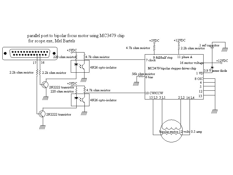
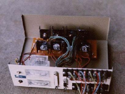


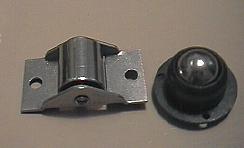
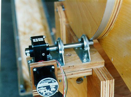
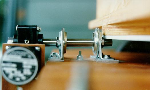
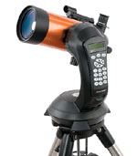
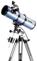
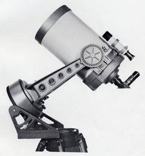
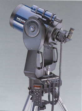
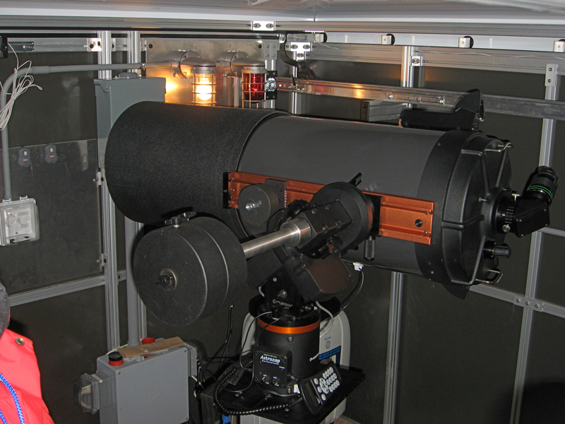
 The dual tine Fork mounted Go To systems (including the Meade LX200 shown above) are usually highly integrated arrangements where the telescope optical tube can not be removed and interchanged easily with another. The requirements for pointing a high magnification system are so stringent the the critical alignment of the optical tube axis to the forks makes it impractical to remove and replace the optical tube. On some more recently developed compact mounts including the single tine Vixen Skypod alt-azimuth arrangement, then it may be a simple matter to change the telescope optical tube as may be desired when attempting a wide variety of applications. Right: Vixen Skypod showing the Star Book Type S console in its dock (66,142 bytes).
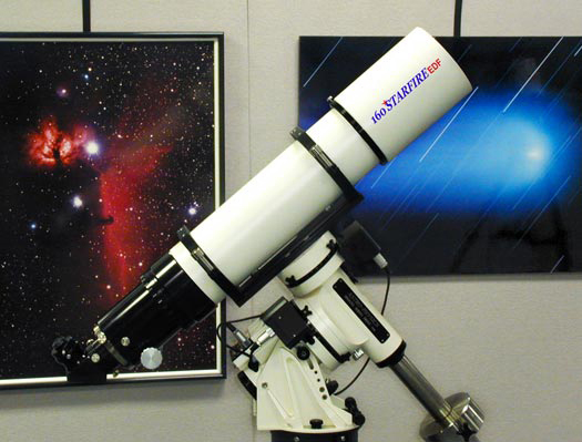 In order to have the capability to change optical tubes while maintaining a high degree of pointing accuracy we recommend German Equatorial mounts. These mounts usually offer the choice of either installing a telescope in a semi permanent bolted on fashion, or they may offer a female Dovetail Saddle with quick release male Dovetail Plate to slide a payload into place. To maintain good pointing accuracy the Saddle and Plates must be long, wide and rigid enough to prevent any flexure or the propagation of resonating vibrations. The Dovetail arrangement allows one to use the mount to support a variety of telescopes over time. So for example, on a first night out you might employ a high resolution refractor to study the Moon and Planets, while on the next night a larger "light bucket" may be put in place of the smaller refractor to permit one to better see fainter objects. Left: Astro-Physics 160mm EDF telescope on their Model 900 GTO Go To German Equatorial Mount (65,309 bytes).
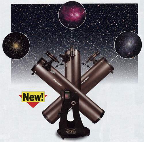

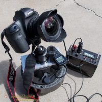
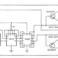

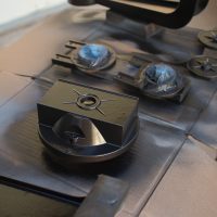
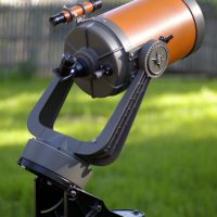
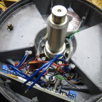
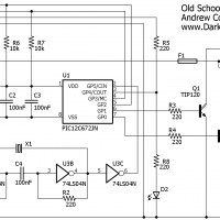


Tidak ada komentar:
Posting Komentar