Electronic devices spectrum of death on so intake human body
Deaths that occur in the human body in addition to wear and tear on some major organs of circulation formation in the human body, especially organ input such as lungs: eye nerve to the brain: the hair into the heart muscle "is also caused by the interval area of the heart and kidney cortex and liver and spleen that trigger conventional convergent pulsations of the brain that can trigger continuous bleeding if possible unstated and un measurable in humans: bleeding leads to unobtrusive and unobtrusive body activity stabilized and integrated: bleeding results in injuries that trigger split blood cells and increase in the nucleus of white blood cells there is a wide range of bleeding on the human body exists from human or human outdoor humans: on the human process of humans> blockage in the organs of organs of the human body usually due to stressful thoughts --- drugs (doping) --- food and liquor ------ work beyond b over normal ---- less ti ur which adds to the dopamine fluid effect on the brain ---- does not chew food well ---- bacteria and worms entering the human body --- the air is not cool and clean --- sex excessive or abnormal: external influences on the human body resulting in bleeding in human organs such as work accidents ---- accidents driving - motorbikes hit; car; train ---- fights resulting in sharp weapon stabbing ---- falling from height ---- natural disasters ---- battles such as hit by bullets or bomb flakes ---- swimming and scuba diving hit the reef and digi git shark - --- also attacked by wild animals; therefore the bleeding on the organs of human vital organs must be able to be detected and measured of course using materials and components of computer electronics devices that are integrated with the trigger of human body sensor then we can call Computerized vital signs analysis may help prevent trauma patients from bleeding to death

The APPRAISE system uses an ultra compact personal computer (left) to analyze data gathered by a standard patient monitor used in emergency transport vehicles (right) to identify trauma patients with life-threatening bleeding. Credit: US Army Medical Research and Materiel Command
Automated analysis of the vital signs commonly monitored in patients being transported to trauma centers could significantly improve the ability to diagnose those with life-threatening bleeding before they arrive at the hospital, potentially saving their lives. In the May issue of the journal Shock, a research team from Massachusetts General Hospital (MGH), the U.S. Army, air ambulance service Boston MedFlight, and two other Boston trauma centers report successful field testing of a system that simultaneously analyzed blood pressure, heart rate, and breathing patterns during emergency transport, finding that it accurately detected most cases of life-threatening bleeding in a fully automated fashion.
"While the clinical information that ambulance crews call in to trauma centers was sufficient to determine the presence of a life-threatening hemorrhage in about half the patients we studied, many other patients were in a 'grey area' and may or may not have been at risk of bleeding to death. Our study demonstrated that automated analysis of patients' vital signs during prehospital transport was significantly better at discriminating between patients who did and did not have life-threatening hemorrhage. Receiving more reliable information before the patient arrives can help hospitals be ready for immediate surgery and replenishment of lost blood without wasting time and resources on false alarms."
Study corresponding author Jaques Reifman, PhD, U.S. Army Medical Research and Materiel Command (USAMRMC), adds, "This system provides an automated indicator of injury severity, an objective way for clinicians to prioritize care. Care prioritization or triage is a very important problem in military medicine, when there may be more injured casualties than caregivers. In those situations the ability to wisely choose who needs priority care is truly a matter of life and death."
While teams transporting patients either by air or ground ambulance regularly notify receiving hospitals of potentially deadly injuries, the information transmitted may be too general to identify those at risk of life-threatening bleeding. Even when a patient is clearly at risk of serious blood loss, decisions about the need for surgical repair and blood transfusions may not be made until assessment is completed at the trauma center. To investigate whether computerized analysis of data being gathered by vital signs monitors during transport could identify patients with dangerous bleeding, the research team developed software based on statistical techniques currently used in stock market trading and manufacturing to determine whether particular data points represent real problems and not random fluctuations.
The system dubbed APPRAISE (Automated Processing of the Physiological Registry for Assessment of Injury Severity) - consisting of an ultracompact personal computer networked to a standard patient monitor - was installed in two MedFlight helicopters and collected data on more than 200 trauma patients transported to participating Boston hospitals from February 2010 to December 2012. In order that patient care not be affected by a still-unproven system, the analysis conducted by the APPRAISE system was not provided to MedFlight crews. The researchers also analyzed data gathered in a 2005 study of vital sign data gathered manually by a Houston-based air ambulance system. Outcomes information for both patient groups was gathered by chart review.
In both groups, the pattern-recognition capability provided by the APPRAISE system - which was able to simultaneously combine measures of blood pressure with those of heart rate, breathing and the amount of blood pumped with each heartbeat - successfully identified 75 to 80 percent of patients with life-threatening bleeding, compared with 50 percent who were identified by standard clinical practice. Notifications provided by the system would have been available within 10 minutes of initial monitoring and as much as 20 to 40 minutes before patients arrival at the trauma centers.
"The fact that decisions to proceed with surgery or to replenish lost blood often occur only after patients' arrival means there are delays - sometimes brief but sometimes prolonged - in initiating such life-saving interventions," says Reisner, an assistant professor of Emergency Medicine at Harvard Medical School. "We are now working on a follow-up study to use this system in actual trauma care and will be measuring whether it truly leads to faster treatment of life-threatening hemorrhage and better patient outcomes. This approach could also be helpful for patients transported by ground ambulance and for hospitalized patients at risk of unexpected hemorrhage, such as during recovery from major surgery."
Reifman adds, "Uncontrolled bleeding is the single most important cause of preventable combat death among our troops, and the first challenge of combat casualty care is to identify who is and who isn't bleeding to death so that available resources can be concentrated on those who most need aid. Evacuation and treatment of injured soldiers can be challenging in locations where active fighting or other hazardous conditions are present, and first responders may be inexperienced, distracted or exhausted. The APPRAISE system's automated, objective assessment of vital signs would rationally determine who needs priority care during military operations."
' bench to bedside to bench': Scientists call for closer basic-clinical collaborations

In the era of genome sequencing, it's time to update the old "bench-to-bedside" shorthand for how basic research discoveries inform clinical practice, researchers from The Jackson Laboratory (JAX), National Human Genome Research Institute (NHGRI) and institutions across the U.S. declare in a Leading Edge commentary in Cell.
"Interactions between basic and clinical researchers should be more like a 'virtuous cycle' of bench to bedside and back again," says JAX Professor Carol Bult, Ph.D., senior author of the commentary. "New technologies to determine the function of genetic variants, together with new ways to share data, mean it's now possible for basic and clinical scientists to build upon each other's work. The goal is to accelerate insights into the genetic causes of disease and the development of new treatments."
Genome sequencing technologies are generating massive quantities of patient data, revealing many new genetic variants. The challenge, says commentary first author Teri Manolio, M.D., Ph.D., director of the NHGRI Division of Genomic Medicine, "is in mining all these data for genes and variants of high clinical relevance."
In April 2016, NHGRI convened a meeting of leading researchers from 26 institutions to explore ways to build better collaborations between basic scientists and clinical genomicists, in order to link genetic variants with disease causation. The Cell commentary outlines the group's recommendations, which include promoting data sharing and prioritizing clinically relevant genes for functional studies.
In order for these collaborations to be most effective, the researchers note, both the basic and clinical research disciplines need better data-management practices. Basic scientists should seek better integration across model systems and focus on standardizing and collecting data on phenotypes (physical characteristics or symptoms) for matching with genomic data. Clinicians should work more closely with the clinical laboratories that perform the genome sequencing; "even better would be a two- or even three-way interchange including the patient as a long-term partner."
The researchers comment, "These efforts individually and collectively hold great promise for bringing basic and clinical researchers and clinicians, and indeed researchers from many other relevant disciplines, together to work on mutually relevant questions that will ultimately benefit them both, the scientific community at large, and most importantly, the patients whom we are all committed to serving."
Touching helps build the sexual brain

Hormones or sexual experience? Which of these is crucial for the onset of puberty? It seems that when rats are touched on their genitals, their brain changes and puberty accelerates. In a new study publishing September 21 in the open access journal PLOS Biology researchers at the Bernstein Center, and Humboldt University, Berlin, led by Constanze Lenschow and Michael Brecht, report that sexual touch might have a bigger influence on puberty than previously thought.
It has been known for some time that social cues can either accelerate or delay puberty in mammals, but it hasn't been clear which signals are crucial, nor how they affect the body and brain, and in particular the possible reorganization of the brain.
The researchers first observed that the neural representation of the genitals in the cerebral cortex expands during puberty. To begin with, the study confirms what was expected; that sexual hormones accelerate puberty and the growth of the so-called 'genital cortex'. However, what's new is that they find that sexual touch also contributes substantially to the acceleration of puberty.
During their study, the scientists first put young female rats together with male rats and found that the genital cortex expanded as a result. This didn't happen when the females were housed with other females, or if the males were separated from them by wire mesh, thereby preventing direct contact. However, they found that the same acceleration of cortical expansion could be observed when the rats' genitals were touched artificially using a lubricated brush.
Lenschow says: "the effects of sexual touch on puberty and the genital cortex are remarkable since you wouldn't expect this area of the brain to expand at this stage of development." Hence, the expansion of the genital cortex is not only triggered by hormones but also by sexual touch.
"The representation of the body changes in the cerebral cortex," says Brecht, "and in particular the genital cortex doubles in size. Our results help to understand why the perception of our body changes so much during puberty." Thus, changes of the body and the concurrent changes in the brain during puberty are not merely a matter of hormones - they are also co-determined by sexual experience.
Highly precise wiring in the cerebral cortex

Nerve cell “trio” (in color) found to be very specifically connected within the dense network of the brain (shown in grey). Credit: MPI for Brain Research
Our brains house extremely complex neuronal circuits whose detailed structures are still largely unknown. This is especially true for the cerebral cortex of mammals, where, among other things, vision, thoughts or spatial orientation are computed. Here, the rules by which nerve cells are connected to each other are only partly understood. A team of scientists around Moritz Helmstaedter at the Max Planck Institute for Brain Research have now discovered a surprisingly precise nerve cell connectivity pattern in the part of the cerebral cortex that is responsible for orienting the individual animal or human in space.
Connectomics researchers have now used their repertoire of measuring and analysis techniques to study the part of the cerebral cortex in which grid cells provide a very particular representation of the space around the individual animal or human. These grid cells are active when the animal or human is located at highly ordered grid-like locations in a room or a large space. Previously, scientists had already found a special arrangement of nerve cells in this region of the brain, and had speculated that within these special cell assemblies, particular nerve cell circuits could exist.

Precise sorting of synapses (in blue and red) within the dense network of the medial entorhinal cortex, reconstructed using connectomic techniques. Credit: MPI for Brain Research
In the current study, the scientists looked at these circuits in more detail and found that, contrary to prior belief, the synapses are exceptionally precisely positioned. Within an extremely dense network of nerve cells, the nerve cells are, in fact, arranged in orderly triplets in which a nerve cell first activates an inhibitory nerve cell. Transfer of the signal to the next excitatory nerve cell can, however, be hindered by the veto of the inhibitory nerve cell. This core circuit, more or less functioning like a cortical transistor, would be able to propagate information in a very selective way, for instance, only when additional information about the context and the surroundings of the animal or the human is available. The nerve cells within this transistor apparently use the very precise positioning of contact sites along their electrically conducting nerve cell cables, called axons. "While many consider the cerebral cortex as a randomly assembled web of nerve cells and have already turned to simulating this random network, we now discover an extremely precise connectivity pattern. In the cerebral cortex, taking a much closer look is clearly worth it," says Helmstaedter.
How brain microcircuits integrate information from different senses
A new publication in the top-ranked journal Neuron sheds new light onto the unknown processes on how the brain integrates the inputs from the different senses in the complex circuits formed by molecularly distinct types of nerve cells. The work was led by new Umeå University associate professor Paolo Medini.
One of the biggest challenges in Neuroscience is to understand how the cerebral cortex of the brain processes and integrates the inputs from the different senses (like vision, hearing and touch) to control for example, that we can respond to an event in the environment with precise movement of our body.
The brain cortex is composed by morphologically and functionally different types of nerve cells, e.g. excitatory, inhibitory, that connect in very precise ways. Paolo Medini and co-workers show that the integration of inputs from different senses in the brain occurs differently in excitatory and inhibitory cells, as well as in superficial and in the deep layers of the cortex, the latter ones being those that send electrical signals out from the cortex to other brain structures.
"The relevance and the innovation of this work is that by combining advanced techniques to visualize the functional activity of many nerve cells in the brain and new molecular genetic techniques that allows us to change the electrical activity of different cell types, we can for the first time understand how the different nerve cells composing brain circuits communicate with each other", says Paolo Medini.
The new knowledge is essential to design much needed future strategies to stimulate brain repair. It is not enough to transplant nerve cells in the lesion site, as the biggest challenge is to re-create or re-activate these precise circuits made by nerve cells.
Paolo Medini has a Medical background and worked in Germany at the Max Planck Institute for Medical Research of Heidelberg, as well as a Team leader at the Italian Institute of Technology in Genova, Italy. He recently started on the Associate Professor position in Cellular and Molecular Physiology at the Molecular Biology Department.
He is now leading a brand new Brain Circuits Lab with state of state-of-the-art techniques such as two-photon microscopy, optogenetics and electrophysiology to investigate the circuit functioning and repair in the brain cortex. This investment has been possible by a generous contribution from the Kempe Foundation and by the combined effort of Umeå University.
"By combining cell physiology knowledge in the intact brain with molecular biology expertise, we plan to pave the way for this kind of innovative research that is new to Umeå University and nationally", says Paolo Medini.
Study reveals potential role of 'love hormone' oxytocin in brain function
In a loud, crowded restaurant, having the ability to focus on the people and conversation at your own table is critical. Nerve cells in the brain face similar challenges in separating wanted messages from background chatter. A key element in this process appears to be oxytocin, typically known as the "love hormone" for its role in promoting social and parental bonding.
In a study appearing online August 4 in Nature, NYU Langone Medical Center researchers decipher how oxytocin, acting as a neurohormone in the brain, not only reduces background noise, but more importantly, increases the strength of desired signals. These findings may be relevant to autism, which affects one in 88 children in the United States.
"Oxytocin has a remarkable effect on the passage of information through the brain," says Richard W. Tsien, DPhil, the Druckenmiller Professor of Neuroscience and director of the Neuroscience Institute at NYU Langone Medical Center. "It not only quiets background activity, but also increases the accuracy of stimulated impulse firing. Our experiments show how the activity of brain circuits can be sharpened, and hint at how this re-tuning of brain circuits might go awry in conditions like autism."
Children and adults with autism-spectrum disorder (ASD) struggle with recognizing the emotions of others and are easily distracted by extraneous features of their environment. Previous studies have shown that children with autism have lower levels of oxytocin, and mutations in the oxytocin receptor gene predispose people to autism. Recent brain recordings from people with ASD show impairments in the transmission of even simple sensory signals.
The current study built upon 30-year old results from researchers in Geneva, who showed that oxytocin acted in the hippocampus, a region of the brain involved in memory and cognition. The hormone stimulated nerve cells – called inhibitory interneurons – to release a chemical called GABA. This substance dampens the activity of the adjoining excitatory nerve cells, known as pyramidal cells.
"From the previous findings, we predicted that oxytocin would dampen brain circuits in all ways, quieting both background noise and wanted signals," Dr. Tsien explains. "Instead, we found that oxytocin increased the reliability of stimulated impulses – good for brain function, but quite unexpected."
To resolve this paradox, Dr. Tsien and his Stanford graduate student Scott Owen collaborated with Gord Fishell, PhD, the Julius Raynes Professor of Neuroscience and Physiology at NYU Langone Medical Center, and NYU graduate student Sebnem Tuncdemir. They identified the particular type of inhibitory interneurons responsible for the effects of oxytocin: "fast-spiking" inhibitory interneurons.
The mystery of how oxytocin drives these fast-spiking inhibitory cells to fire, yet also increases signaling to pyramidal neurons, was solved through studies with rodent models. The researchers found that continually activating the fast-spiking inhibitory neurons – good for lowering background noise – also causes their GABA-releasing synapses to fatigue. Accordingly, when a stimulus arrives, the tired synapses release less GABA and excitation of the pyramidal neuron is not dampened as much, so that excitation drives the pyramidal neuron's firing more reliably.
"The stronger signal and muffled background noise arise from the same fundamental action of oxytocin and give two benefits for the price of one," Dr. Fishell explains. "It's too early to say how the lack of oxytocin signaling is involved in the wide diversity of autism-spectrum disorders, and the jury is still out about its possible therapeutic effects. But it is encouraging to find that a naturally occurring neurohormone can enhance brain circuits by dialing up wanted signals while quieting background noise."
Study links brain inflammation to suicidal thinking in depression

Patients with major depressive disorder (MDD) have increased brain levels of a marker of microglial activation, a sign of inflammation, according to a new study in Biological Psychiatry by researchers at the University of Manchester, United Kingdom. In the study, Dr. Peter Talbot and colleagues found that the increase in the inflammatory marker was present specifically in patients with MDD who were experiencing suicidal thoughts, pinning the role of inflammation to suicidality rather than a diagnosis of MDD itself.
"Our findings are the first results in living depressed patients to suggest that this microglial activation is most prominent in those with suicidal thinking," said Dr. Talbot. Previous studies suggesting this link have relied on brain tissue collected from patients after death.
"This paper is an important addition to the view that inflammation is a feature of the neurobiology of a subgroup of depressed patients, in this case the group with suicidal ideation," said Dr. John Krystal, Editor of Biological Psychiatry. "This observation is particularly important in light of recent evidence supporting a personalized medicine approach to depression, i.e., that anti-inflammatory drugs may have antidepressant effects that are limited to patients with demonstrable inflammation."
In the study, first author Dr. Sophie Holmes and colleagues assessed inflammation in 14 patients with moderate-to-severe depression who were not currently taking any antidepressant medications. Immune cells called microglia activate as part of the body's inflammatory response, so the researchers used a brain imaging technique to measure a substance that increases in activated microglia.
The evidence for immune activation was most prominent in the anterior cingulate cortex, a brain region involved in mood regulation and implicated in the biological origin of depression, confirming the results of a previous study that first identified altered microglial activation in medication-free MDD patients. Smaller increases were also found in the insula and prefrontal cortex.
"The field now has two independent reports—our study and a 2015 report by Setiawan and colleagues in Toronto—showing essentially the same thing: that there is evidence for inflammation, more specifically microglial activation, in the brains of living patients during a major depressive episode," said Dr. Talbot.
This link suggests that among depressed patients, neuroinflammation may be a factor contributing to the risk for suicidal thoughts or behavior. According to Dr. Talbot, the findings "emphasise the importance of further research into the question of whether novel treatments that reduce microglial activation may be effective in major depression and suicidality."
computer electronics devices that are integrated with the trigger of human body sensor on concept Dead time electronic devices
For detection systems that record discrete events, such as particle and nuclear detectors, the dead time is the time after each event during which the system is not able to record another event.An everyday life example of this is what happens when someone takes a photo using a flash - another picture cannot be taken immediately afterward because the flash needs a few seconds to recharge. In addition to lowering the detection efficiency, dead times can have other effects, such as creating possible exploits in quantum cryptography
The total dead time of a detection system is usually due to the contributions of the intrinsic dead time of the detector (for example the drift time in a gaseous ionization detector), of the analog front end (for example the shaping time of a spectroscopy amplifier) and of the data acquisition (the conversion time of the analog-to-digital converters and the readout and storage times).
The intrinsic dead time of a detector is often due to its physical characteristics; for example a spark chamber is "dead" until the potential between the plates recovers above a high enough value. In other cases the detector, after a first event, is still "live" and does produce a signal for the successive event, but the signal is such that the detector readout is unable to discriminate and separate them, resulting in an event loss or in a so-called "pile-up" event where, for example, a (possibly partial) sum of the deposited energies from the two events is recorded instead. In some cases this can be minimised by an appropriate design, but often only at the expense of other properties like energy resolution.
The analog electronics can also introduce dead time; in particular a shaping spectroscopy amplifier needs to integrate a fast rise, slow fall signal over the longest possible time (usually from .5 up to 10 microseconds) to attain the best possible resolution, such that the user needs to choose a compromise between event rate and resolution.
Trigger logic is another possible source of dead time; beyond the proper time of the signal processing, spurious triggers caused by noise need to be taken into account.
Finally, digitisation, readout and storage of the event, especially in detection systems with large number of channels like those used in modern High Energy Physics experiments, also contribute to the total dead time. To alleviate the issue, medium and large experiments use sophisticated pipelining and multi-level trigger logic to reduce the readout rates.
From the total time a detection system is running, the dead time must be subtracted to obtain the live time.
Paralyzable and non-paralyzable behaviour
A detector, or detection system, can be characterized by a paralyzable or non-paralyzable behaviour. In a non-paralyzable detector, an event happening during the dead time is simply lost, so that with an increasing event rate the detector will reach a saturation rate equal to the inverse of the dead time. In a paralyzable detector, an event happening during the dead time will not just be missed, but will restart the dead time, so that with increasing rate the detector will reach a saturation point where it will be incapable of recording any event at all. A semi-paralyzable detector exhibits an intermediate behaviour, in which the event arriving during dead time does extend it, but not by the full amount, resulting in a detection rate that decreases when the event rate approaches saturation.Analysis
It will be assumed that the events are occurring randomly with an average frequency of f. That is, they constitute a Poisson process. The probability that an event will occur in an infinitesimal time interval dt is then f dt. It follows that the probability P(t) that an event will occur at time t to t+dt with no events occurring between t=0 and time t is given by the exponential distribution (Lucke 1974, Meeks 2008):

Non-paralyzable analysis
For the non-paralyzable case, with a dead time of , the probability of measuring an event between and is zero. Otherwise the probabilities of measurement are the same as the event probabilities. The probability of measuring an event at time t with no intervening measurements is then given by an exponential distribution shifted by :


- for


- for


Time-To-Count
With a modern microprocessor based ratemeter one technique for measuring field strength with detectors (e.g., Geiger–Müller tubes) with a recovery time is Time-To-Count. In this technique, the detector is armed at the same time a counter is started. When a strike occurs, the counter is stopped. If this happens many times in a certain time period (e.g., two seconds), then the mean time between strikes can be determined, and thus the count rate. Live time, dead time, and total time are thus measured, not estimated. This technique is used quite widely in radiation monitoring systems used in nuclear power generating stations.Data acquisition
Data acquisition is the process of sampling signals that measure real world physical conditions and converting the resulting samples into digital numeric values that can be manipulated by a computer. Data acquisition systems, abbreviated by the acronyms DAS or DAQ, typically convert analog waveforms into digital values for processing. The components of data acquisition systems include:
- Sensors, to convert physical parameters to electrical signals.
- Signal conditioning circuitry, to convert sensor signals into a form that can be converted to digital values.
- Analog-to-digital converters, to convert conditioned sensor signals to digital values.

There are also open-source software packages providing all the necessary tools to acquire data from different hardware equipment. These tools come from the scientific community where complex experiment requires fast, flexible and adaptable software. Those packages are usually custom fit but more general DAQ package like the Maximum Integrated Data Acquisition System can be easily tailored and is used in several physics experiments worldwide.
In 1963, IBM produced computers which specialized in data acquisition. These include the IBM 7700 Data Acquisition System, and its successor, the IBM 1800 Data Acquisition and Control System. These expensive specialized systems were surpassed in 1974 by general purpose S-100 computers and data acquisitions cards produced by Tecmar/Scientific Solutions Inc. In 1981 IBM introduced the IBM Personal Computer and Scientific Solutions introduced the first PC data acquisition products.
Sources and systems
Data acquisition begins with the physical phenomenon or physical property to be measured. Examples of this include temperature, light intensity, gas pressure, fluid flow, and force. Regardless of the type of physical property to be measured, the physical state that is to be measured must first be transformed into a unified form that can be sampled by a data acquisition system. The task of performing such transformations falls on devices called sensors. A data acquisition system is a collection of software and hardware that lets you measure or control physical characteristics of something in the real world. A complete data acquisition system consists of DAQ hardware, sensors and actuators, signal conditioning hardware, and a computer running DAQ software.A sensor, which is a type of transducer, is a device that converts a physical property into a corresponding electrical signal (e.g., strain gauge, thermistor). An acquisition system to measure different properties depends on the sensors that are suited to detect those properties. Signal conditioning may be necessary if the signal from the transducer is not suitable for the DAQ hardware being used. The signal may need to be filtered or amplified in most cases. Various other examples of signal conditioning might be bridge completion, providing current or voltage excitation to the sensor, isolation, linearization. For transmission purposes, single ended analog signals, which are more susceptible to noise can be converted to differential signals. Once digitized, the signal can be encoded to reduce and correct transmission errors.
DAQ hardware
DAQ hardware is what usually interfaces between the signal and a PC.[6] It could be in the form of modules that can be connected to the computer's ports (parallel, serial, USB, etc.) or cards connected to slots (S-100 bus, AppleBus, ISA, MCA, PCI, PCI-E, etc.) in the motherboard. Usually the space on the back of a PCI card is too small for all the connections needed, so an external breakout box is required. The cable between this box and the PC can be expensive due to the many wires, and the required shielding.DAQ cards often contain multiple components (multiplexer, ADC, DAC, TTL-IO, high speed timers, RAM). These are accessible via a bus by a microcontroller, which can run small programs. A controller is more flexible than a hard wired logic, yet cheaper than a CPU so that it is permissible to block it with simple polling loops. For example: Waiting for a trigger, starting the ADC, looking up the time, waiting for the ADC to finish, move value to RAM, switch multiplexer, get TTL input, let DAC proceed with voltage ramp.
DAQ device drivers
DAQ device drivers are needed in order for the DAQ hardware to work with a PC. The device driver performs low-level register writes and reads on the hardware, while exposing API for developing user applications in a variety of proInput devices
Hardware
- Computer Automated Measurement and Control (CAMAC)
- Industrial Ethernet
- Industrial USB
- LAN eXtensions for Instrumentation
- NIM
- PowerLab
- PCI eXtensions for Instrumentation
- VMEbus
- VXI
DAQ software
Specialized DAQ software may be delivered with the DAQ hardware. Software tools used for building large-scale data acquisition systems include EPICS. Other programming environments that are used to build DAQ applications include ladder logic, Visual C++, Visual Basic, LabVIEW, and MATLAB. See also:Allan variance
The Allan variance (AVAR), also known as two-sample variance, is a measure of frequency stability in clocks, oscillators and amplifiers, named after David W. Allan and expressed mathematically as . The Allan deviation (ADEV), also known as sigma-tau, is the square root of Allan variance, .


The M-sample variance is a measure of frequency stability using M samples, time T between measures and observation time . M-sample variance is expressed as

There are also different adaptations or alterations of Allan variance, notably the modified Allan variance MAVAR or MVAR, the total variance, and the Hadamard variance. There also exist time stability variants such as time deviation TDEV or time variance TVAR. Allan variance and its variants have proven useful outside the scope of timekeeping and are a set of improved statistical tools to use whenever the noise processes are not unconditionally stable, thus a derivative exists.
The general M-sample variance remains important since it allows dead time in measurements and bias functions allows conversion into Allan variance values. Nevertheless, for most applications the special case of 2-sample, or "Allan variance" with is of greatest interest.


Example plot of the Allan deviation of a clock. At very short observation time τ, the Allan deviation is high due to noise. At longer τ, it decreases because the noise averages out. At still longer τ, the Allan deviation starts increasing again, suggesting that the clock frequency is gradually drifting due to temperature changes, aging of components, or other such factors. The error bars increase with τ simply because it is time-consuming to get a lot of data points for large τ.

A clock is most easily tested by comparing it with a far more accurate reference clock. During an interval of time τ, as measured by the reference clock, the clock under test advances by τy, where y is the average (relative) clock frequency over that interval. If we measure two consecutive intervals as shown, we can get a value of (y − y′)2—a smaller value indicates a more stable and precise clock. If we repeat this procedure many times, the average value of (y − y′)2 is equal to twice the Allan variance (or Allan deviation squared) for observation time τ.
When investigating the stability of crystal oscillators and atomic clocks it was found that they did not have a phase noise consisting only of white noise, but also of white frequency noise and flicker frequency noise. These noise forms become a challenge for traditional statistical tools such as standard deviation as the estimator will not converge. The noise is thus said to be divergent. Early efforts in analysing the stability included both theoretical analysis and practical measurements.[1][2]
An important side-consequence of having these types of noise was that, since the various methods of measurements did not agree with each other, the key aspect of repeatability of a measurement could not be achieved. This limits the possibility to compare sources and make meaningful specifications to require from suppliers. Essentially all forms of scientific and commercial uses were then limited to dedicated measurements which hopefully would capture the need for that application.
To address these problems, David Allan introduced the M-sample variance and (indirectly) the two-sample variance.[3] While the two-sample variance did not completely allow all types of noise to be distinguished, it provided a means to meaningfully separate many noise-forms for time-series of phase or frequency measurements between two or more oscillators. Allan provided a method to convert between any M-sample variance to any N-sample variance via the common 2-sample variance, thus making all M-sample variances comparable. The conversion mechanism also proved that M-sample variance does not converge for large M, thus making them less useful. IEEE later identified the 2-sample variance as the preferred measure.[4]
An early concern was related to time and frequency measurement instruments which had a dead time between measurements. Such a series of measurements did not form a continuous observation of the signal and thus introduced a systematic bias into the measurement. Great care was spent in estimating these biases. The introduction of zero dead time counters removed the need, but the bias analysis tools have proved useful.
Another early aspect of concern was related to how the bandwidth of the measurement instrument would influence the measurement, such that it needed to be noted. It was later found that by algorithmically changing the observation , only low values would be affected while higher values would be unaffected. The change of is done by letting it be an integer multiple of the measurement timebase .
Allan deviation is widely used for plots (conveniently in log-log format) and presentation of numbers. It is preferred as it gives the relative amplitude stability, allowing ease of comparison with other sources of errors.
An Allan deviation of 1.3×10⁻⁹ at observation time 1 s (i.e. τ = 1 s) should be interpreted as there being an instability in frequency between two observations a second apart with a relative root mean square (RMS) value of 1.3×10⁻⁹. For a 10-MHz clock, this would be equivalent to 13 mHz RMS movement. If the phase stability of an oscillator is needed then the time deviation variants should be consulted and used.
One may convert the Allan variance and other time-domain variances into frequency-domain measures of time (phase) and frequency stability.
An important aspect is that -sample variance model can include dead-time by letting the time be different from that of .
The samples are taken with no dead-time between them, which is achieved by letting
Since y(t) is the derivative of x(t), we can without loss of generality rewrite it as
The time error sample series let N denote the number of samples (x0...xN-1) in the series. The traditional convention uses index 1 through N.
As a shorthand, average fractional frequency is often written without the average bar over it. This is however formally incorrect as the fractional frequency and average fractional frequency are two different functions. A measurement instrument able to produce frequency estimates with no dead-time will actually deliver a frequency average time series which only needs to be converted into average fractional frequency and may then be used directly.
and for the time series
These estimators have a significant drawback in that they will drop a significant amount of sample data as only 1/n of the available samples is being used.
As found in[10][11] and in modern forms.
The Allan variance is unable to distinguish between WPM and FPM, but is able to resolve the other power-law noise types. In order to distinguish WPM and FPM, the modified Allan variance needs to be employed.
The above formulas assume that
The mapping is taken from.[4]
Thus, linear drift will contribute to output result. When measuring a real system, the linear drift or other drift mechanism may need to be estimated and removed from the time-series prior to calculating the Allan variance.[12]
These bias functions are not sufficient for handling the bias resulting from concatenating M samples to the Mτ0 observation time over the MT0 with has the dead-time distributed among the M measurement blocks rather than at the end of the measurement. This rendered the need for the B3 bias.[15]
The bias functions are evaluated for a particular µ value, so the α-µ mapping needs to be done for the dominant noise form as found using noise identification. Alternatively as proposed in[3] and elaborated in[14] the µ value of the dominant noise form may be inferred from the measurements using the bias functions.
The bias function becomes after analysis (for the N=2 case)
If however one adjust the bandwidth of the estimator by using integer multiples of the sample time then the system bandwidth impact can be reduced to insignificant levels. For telecommunication needs, such methods have been required in order to ensure comparability of measurements and allow some freedom for vendors to do different implementations. The ITU-T Rec. G.813[16] for the TDEV measurement.
It can be recommended that the first multiples be ignored such that the majority of the detected noise is well within the passband of the measurement systems bandwidth.
Further developments on the Allan variance was performed to let the hardware bandwidth be reduced by software means. This development of a software bandwidth allowed for addressing the remaining noise and the method is now referred to modified Allan variance. This bandwidth reduction technique should not be confused with the enhanced variant of modified Allan variance which also changes a smoothing filter bandwidth.
Dead time effects on measurements have such an impact on the produced result that much study of the field have been done in order to quantify its properties properly. The introduction of zero dead-time counters removed the need for this analysis. A zero dead-time counter has the property that the stop-event of one measurement is also being used as the start-event of the following event. Such counters creates a series of event and time timestamp pairs, one for each channel spaced by the time-base. Such measurements have also proved useful in order forms of time-series analysis.
Measurements being performed with dead time can be corrected using the bias function B1, B2 and B3. Thus, dead time as such is not prohibiting the access to the Allan variance, but it makes it more problematic. The dead time must be known such that the time between samples T can be established.
The effect may be that the estimated value may be much smaller or much greater than the real value, which may lead to false conclusions of the result.
It is recommended that the confidence interval is plotted along with the data, such that the reader of the plot is able to be aware of the statistical uncertainty of the values.
It is recommended that the length of the sample sequence, i.e. the number of samples N is kept high to ensure that confidence interval is small over the τ-range of interest.
It is recommended that the τ-range as swept by the τ0 multiplier n is limited in the upper end relative N such that the read of the plot is not being confused by highly unstable estimator values.
It is recommended that estimators providing better degrees of freedom values be used in replacement of the Allan variance estimators or as complementing them where they outperform the Allan variance estimators. Among those the Total variance and Theo variance estimators should be considered.
In order to provide evenly spaced measurements will the reference clock be divided down to form the measurement rate, triggering the time-interval counter (ARM input). This rate can be 1 Hz (using the 1 PPS output of a reference clock) but other rates like 10 Hz and 100 Hz can also be used. The speed of which the time-interval counter can complete the measurement, output the result and prepare itself for the next arm will limit the trigger frequency.
A computer is then useful to record the series of time-differences being observed.
The Allan variance can then be calculated using the estimators given, and for practical purposes the overlapping estimator should be used due to its superior use of data over the non-overlapping estimator. Other estimators such as Total or Theo variance estimators could also be used if bias corrections is applied such that they provide Allan variance compatible results.
To form the classical plots, the Allan deviation (square root of Allan variance) is plotted in log-log format against the observation interval tau.
The NASA-IEEE Symposium on Short-Term Stability in November 1964[20] brought together many fields and uses of short and long term stability with papers from many different contributors. The articles and panel discussions is interesting in that they concur on the existence of the frequency flicker noise and the wish to achieve a common definition for short and long term stability (even if the conference name only reflect the short-term stability intention).
The IEEE proceedings on Frequency Stability 1966 included a number of important papers including those of David Allan,[3] James A. Barnes,[21] L. S. Cutler and C. L. Searle[1] and D. B. Leeson.[2] These papers helped shape the field.
The classical M-sample variance of frequency was analysed by David Allan in[3] along with an initial bias function. This paper tackles the issues of dead-time between measurements and analyses the case of M frequency samples (called N in the paper) and variance estimators. It provides the now standard α to µ mapping. It clearly builds on James Barnes work as detailed in his article[21] in the same issue. The initial bias functions introduced assumes no dead-time, but the formulas presented includes dead-time calculations. The bias function assumes the use of the 2-sample variance as a base-case, since any other variants of M may be chosen and values may be transferred via the 2-sample variance to any other variance for of arbitrary M. Thus, the 2-sample variance was only implicitly used and not clearly stated as the preference even if the tools where provided. It however laid the foundation for using the 2-sample variance as the base case of comparison among other variants of the M-sample variance. The 2-sample variance case is a special case of the M-sample variance which produces an average of the frequency derivative.
The work on bias functions was significantly extended by James Barnes in[14] in which the modern B1 and B2 bias functions was introduced. Curiously enough, it refers to the M-sample variance as "Allan variance" while referencing to Allan's paper "Statistics of Atomic Frequency Standards".[3] With these modern bias functions, full conversion among M-sample variance measures of variating M, T and τ values could used, by conversion through the 2-sample variance.
James Barnes and David Allan further extended the bias functions with the B3 function in[15] to handle the concatenated samples estimator bias. This was necessary to handle the new use of concatenated sample observations with dead time in between.
The IEEE Technical Committee on Frequency and Time within the IEEE Group on Instrumentation & Measurements provided a summary of the field in 1970 published as NBS Technical Notice 394.[10] This paper could be considered first in a line of more educational and practical papers aiding the fellow engineers in grasping the field. In this paper the 2-sample variance with T=τ is being the recommended measurement and it is referred to as Allan variance (now without the quotes). The choice of such parametrisation allows good handling of some noise forms and to get comparable measurements, it is essentially the least common denominator with the aid of the bias functions B1 and B2.
An improved method for using sample statistics for frequency counters in frequency estimation or variance estimation was proposed by J.J. Snyder.[6] The trick to get more effective degrees of freedom out of the available dataset was to use overlapping observation periods. This provides a square-root n improvement. It was included into the overlapping Allan variance estimator introduced in.[7] The variable τ software processing was also included in.[7] This development improved the classical Allan variance estimators likewise providing a direct inspiration going into the work on modified Allan variance.
The confidence interval and degrees of freedom analysis, along with the established estimators was presented in.[7]
The first meaningful summary is the NBS Technical Note 394 "Characterization of Frequency Stability".[10] This is the product of the Technical Committee on Frequency and Time of the IEEE Group on Instrumentation & Measurement. It gives the first overview of the field, stating the problems, defining the basic supporting definitions and getting into Allan variance, the bias functions B1 and B2, the conversion of time-domain measures. This is useful as it is among the first references to tabulate the Allan variance for the five basic noise types.
A classical reference is the NBS Monograph 140[22] from 1974, which in chapter 8 has "Statistics of Time and Frequency Data Analysis".[23] This is the extended variant of NBS Technical Note 394 and adds essentially in measurement techniques and practical processing of values.
An important addition will be the Properties of signal sources and measurement methods.[7] It covers the effective use of data, confidence intervals, effective degree of freedom likewise introducing the overlapping Allan variance estimator. It is a highly recommended reading for those topics.
The IEEE standard 1139 Standard definitions of Physical Quantities for Fundamental Frequency and Time Metrology[4] is beyond that of a standard a comprehensive reference and educational resource.
A modern book aimed towards telecommunication is Stefano Bregni "Synchronisation of Digital Telecommunication Networks".[12] This summarises not only the field but also much of his research in the field up to that point. It aims to include both classical measures likewise telecommunication specific measures such as MTIE. It is a handy companion when looking at telecommunication standard related measurements.
The NIST Special Publication 1065 "Handbook of Frequency Stability Analysis" of W.J. Riley[13] is a recommended reading for anyone wanting to pursue the field. It is rich of references and also covers a wide range of measures, biases and related functions that a modern analyst should have available. Further it describes the overall processing needed for a modern tool.
An important side-consequence of having these types of noise was that, since the various methods of measurements did not agree with each other, the key aspect of repeatability of a measurement could not be achieved. This limits the possibility to compare sources and make meaningful specifications to require from suppliers. Essentially all forms of scientific and commercial uses were then limited to dedicated measurements which hopefully would capture the need for that application.
To address these problems, David Allan introduced the M-sample variance and (indirectly) the two-sample variance.[3] While the two-sample variance did not completely allow all types of noise to be distinguished, it provided a means to meaningfully separate many noise-forms for time-series of phase or frequency measurements between two or more oscillators. Allan provided a method to convert between any M-sample variance to any N-sample variance via the common 2-sample variance, thus making all M-sample variances comparable. The conversion mechanism also proved that M-sample variance does not converge for large M, thus making them less useful. IEEE later identified the 2-sample variance as the preferred measure.[4]
An early concern was related to time and frequency measurement instruments which had a dead time between measurements. Such a series of measurements did not form a continuous observation of the signal and thus introduced a systematic bias into the measurement. Great care was spent in estimating these biases. The introduction of zero dead time counters removed the need, but the bias analysis tools have proved useful.
Another early aspect of concern was related to how the bandwidth of the measurement instrument would influence the measurement, such that it needed to be noted. It was later found that by algorithmically changing the observation , only low values would be affected while higher values would be unaffected. The change of is done by letting it be an integer multiple of the measurement timebase .


Interpretation of value
Allan variance is defined as one half of the time average of the squares of the differences between successive readings of the frequency deviation sampled over the sampling period. The Allan variance depends on the time period used between samples: therefore it is a function of the sample period, commonly denoted as τ, likewise the distribution being measured, and is displayed as a graph rather than a single number. A low Allan variance is a characteristic of a clock with good stability over the measured period.Allan deviation is widely used for plots (conveniently in log-log format) and presentation of numbers. It is preferred as it gives the relative amplitude stability, allowing ease of comparison with other sources of errors.
An Allan deviation of 1.3×10⁻⁹ at observation time 1 s (i.e. τ = 1 s) should be interpreted as there being an instability in frequency between two observations a second apart with a relative root mean square (RMS) value of 1.3×10⁻⁹. For a 10-MHz clock, this would be equivalent to 13 mHz RMS movement. If the phase stability of an oscillator is needed then the time deviation variants should be consulted and used.
One may convert the Allan variance and other time-domain variances into frequency-domain measures of time (phase) and frequency stability.
Definitions
M-sample variance
The -sample variance is defined[3] (here in a modernized notation form) as
![\sigma _{y}^{2}(M,T,\tau )={\frac {1}{M-1}}\left\{\sum _{{i=0}}^{{M-1}}\left[{\frac {x(iT+\tau )-x(iT)}{\tau }}\right]^{2}-{\frac {1}{M}}\left[\sum _{{i=0}}^{{M-1}}{\frac {x(iT+\tau )-x(iT)}{\tau }}\right]^{2}\right\}](https://wikimedia.org/api/rest_v1/media/math/render/svg/0ce77d4bdb1c3e2dcce0fc1ce9639552eaf9c24f)


![\sigma _{y}^{2}(M,T,\tau )={\frac {1}{M-1}}\left\{\sum _{{i=0}}^{{M-1}}{\bar {y}}_{i}^{2}-{\frac {1}{M}}\left[\sum _{{i=0}}^{{M-1}}{\bar {y}}_{i}\right]^{2}\right\}](https://wikimedia.org/api/rest_v1/media/math/render/svg/b6f2499dc8fa4331585b085b2c71d8ff23cd8afa)
An important aspect is that -sample variance model can include dead-time by letting the time be different from that of .
Allan variance
The Allan variance is defined as


The samples are taken with no dead-time between them, which is achieved by letting

Allan deviation
Just as with standard deviation and variance, the Allan deviation is defined as the square root of the Allan variance.
Supporting definitions
Oscillator model
The oscillator being analysed is assumed to follow the basic model of


Time error
The time error function x(t) is the difference between expected nominal time and actual normal time

Frequency function
The frequency function is the frequency over time defined as

Fractional frequency
The fractional frequency y(t) is the normalized difference between the frequency and the nominal frequency :
Average fractional frequency
The average fractional frequency is defined as
Since y(t) is the derivative of x(t), we can without loss of generality rewrite it as

Estimators
This definition is based on the statistical expected value, integrating over infinite time. The real world situation does not allow for such time-series, in which case a statistical estimator needs to be used in its place. A number of different estimators will be presented and discussed.Conventions
- The number of frequency samples in a fractional frequency series is denoted with M.
- The number of time error samples in a time error series is denoted with N.

- For time error sample series, xi denotes the i-th sample of the continuous time function x(t) as given by

The time error sample series let N denote the number of samples (x0...xN-1) in the series. The traditional convention uses index 1 through N.
- For average fractional frequency sample series, denotes the ith sample of the average continuous fractional frequency function y(t) as given by


As a shorthand, average fractional frequency is often written without the average bar over it. This is however formally incorrect as the fractional frequency and average fractional frequency are two different functions. A measurement instrument able to produce frequency estimates with no dead-time will actually deliver a frequency average time series which only needs to be converted into average fractional frequency and may then be used directly.
- It is further a convention to let τ denote the nominal time-difference between adjacent phase or frequency samples. A time series taken for one time-difference τ0 can be used to generate Allan variance for any τ being an integer multiple of τ0 in which case τ=nτ0 are being used, and n becomes a variable for the estimator.
- The time between measurements is denoted with T, which is the sum of observation time τ and dead-time.
Fixed τ estimators
A first simple estimator would be to directly translate the definition into

Non-overlapped variable τ estimators
Taking the time-series and skipping past n−1 samples, a new (shorter) time-series would occur with τ0 as the time between the adjacent samples, for which the Allan variance could be calculated with the simple estimators. These could be modified to introduce the new variable n such that no new time-series would have to be generated, but rather the original time series could be reused for various values of n. The estimators become

and for the time series


These estimators have a significant drawback in that they will drop a significant amount of sample data as only 1/n of the available samples is being used.
Overlapped variable τ estimators
A technique presented by J.J. Snyder[6] provided an improved tool, as measurements were overlapped in n overlapped series out of the original series. The overlapping Allan variance estimator was introduced in.[7] This can be shown to be equivalent to averaging the time or normalized frequency samples in blocks of n samples prior to processing. The resulting predictor becomes

Modified Allan variance
In order to address the inability to separate white phase modulation from flicker phase modulation using traditional Allan variance estimators, an algorithmic filtering reduces the bandwidth by n. This filtering provides a modification to the definition and estimators and it now identifies as a separate class of variance called modified Allan variance. The modified Allan variance measure is a frequency stability measure, just as is the Allan variance.Time stability estimators
A time stability (σx) statistical measure which is often called the time deviation (TDEV) can be calculated from the modified Allan deviation (MDEV). The TDEV is based on the MDEV instead of the original Allan deviation, because the MDEV can discriminate between white and flicker phase modulation (PM). The following is the time variance estimation based on the modified Allan variance:
- The TDEV is normalized so that it is equal to the classical deviation for white PM for time constant τ= τ0. To understand the normalization scale factor between the statistical measures of MDEV and TDEV, the following is the relevant statistical rule. For independent random variables X and Y, the variance (σz2) of a sum or difference (z=x-y) is the sum square of their variances (σz2 = σx2+ σy2). The variance of the sum or difference (y = x2τ-xτ) of two independent samples of a random variable is twice the variance of the random variable (σy2=2σx2). The MDEV is the second difference of independent phase measurements (x) that have a variance (σx2). Since the calculation is the double difference which requires three independent phase measurements (x2τ-2xτ+x), the modified Allan variance (MVAR) is three times the variances of the phase measurements.

Other estimators
Further developments have produced improved estimation methods for the same stability measure, the variance/deviation of frequency, but these are known by separate names such as the Hadamard variance, modified Hadamard variance, the total variance, modified total variance and the Theo variance. These distinguish themselves in better use of statistics for improved confidence bounds or ability to handle linear frequency drift.Confidence intervals and equivalent degrees of freedom
Statistical estimators will calculate an estimated value on the sample series used. The estimates may deviate from the true value and the range of values which for some probability will contain the true value is referred to as the confidence interval. The confidence interval depends on the number of observations in the sample series, the dominant noise type, and the estimator being used. The width is also dependent on the statistical certainty for which the confidence interval values forms a bounded range, thus the statistical certainty that the true value is within that range of values. For variable-τ estimators, the τ0 multiple n is also a variable.Confidence interval
The confidence interval can be established using chi-squared distribution by using the distribution of the sample variance:[4][7]


Effective degrees of freedom
The degrees of freedom represents the number of free variables capable of contributing to the estimate. Depending on the estimator and noise type, the effective degrees of freedom varies. Estimator formulas depending on N and n has been empirically found[7] to be:| Noise type | degrees of freedom |
| white phase modulation (WPM) | |
| flicker phase modulation (FPM) | |
| white frequency modulation (WFM) | |
| flicker frequency modulation (FFM) | |
| random walk frequency modulation (RWFM) |

![d.f.\cong \exp \left[\left(\ln {\frac {N-1}{2n}}\ln {\frac {(2n+1)(N-1)}{4}}\right)^{{-1/2}}\right]](https://wikimedia.org/api/rest_v1/media/math/render/svg/36660b15b326824c0067864bbec8033234b2aca9)
![d.f.\cong \left[{\frac {3(N-1)}{2n}}-{\frac {2(N-2)}{N}}\right]{\frac {4n^{2}}{4n^{2}+5}}](https://wikimedia.org/api/rest_v1/media/math/render/svg/d9a40c017a787297d30bc5e1b2a1b1cbafd969fa)


Power-law noise
The Allan variance will treat various power-law noise types differently, conveniently allowing them to be identified and their strength estimated. As a convention, the measurement system width (high corner frequency) is denoted fH.| Power-law noise type | Phase noise slope | Frequency noise slope | Power coefficient | Phase noise | Allan variance | Allan deviation |
| white phase modulation (WPM) | ||||||
| flicker phase modulation (FPM) | ||||||
| white frequency modulation (WFM) | ||||||
| flicker frequency modulation (FFM) | ||||||
| random walk frequency modulation (RWFM) |


![\sigma _{y}^{2}(\tau )={\frac {3[\gamma +\ln(2\pi f_{H}\tau )]-\ln 2}{4\pi ^{2}\tau ^{2}}}h_{1}](https://wikimedia.org/api/rest_v1/media/math/render/svg/985fd9373cb87c2ba9c785ba7c0d81e6339ae325)
![{\displaystyle \sigma _{y}(\tau )={\frac {\sqrt {3[\gamma +\ln(2\pi f_{H}\tau )]-\ln 2}}{2\pi \tau }}{\sqrt {h_{1}}}}](https://wikimedia.org/api/rest_v1/media/math/render/svg/b0367f3470faa3dc9736286f862bae7e92023182)


The Allan variance is unable to distinguish between WPM and FPM, but is able to resolve the other power-law noise types. In order to distinguish WPM and FPM, the modified Allan variance needs to be employed.
The above formulas assume that

α-μ mapping
The detailed mapping of a phase modulation of the form


| α | β | μ | Kα |
| -2 | -4 | 1 | |
| -1 | -3 | 0 | |
| 0 | -2 | -1 | |
| 1 | -1 | -2 | |
| 2 | 0 | -2 |


![{\frac {3[\gamma +\ln(2\pi f_{H}\tau )]-\ln 2}{4\pi ^{2}}}](https://wikimedia.org/api/rest_v1/media/math/render/svg/a4dd406202f5812cefb2862240cfd67ce87454dc)

General Conversion from Phase Noise
A signal with spectral phase noise with units rad2/Hz can be converted to Allan Variance by:[13]

Linear response
While Allan variance is intended to be used to distinguish noise forms, it will depend on some but not all linear responses to time. They are given in the table:| Linear effect | time response | frequency response | Allan variance | Allan deviation |
|---|---|---|---|---|
| phase offset | ||||
| frequency offset | ||||
| linear drift |


Time and frequency filter properties
In analysing the properties of Allan variance and friends, it has proven useful to consider the filter properties on the normalize frequency. Starting with the definition for Allan variance for


Bias functions
The M-sample variance, and the defined special case Allan variance, will experience systematic bias depending on different number of samples M and different relationship between T and τ. In order address these biases the bias-functions B1 and B2 has been defined[14] and allows for conversion between different M and T values.These bias functions are not sufficient for handling the bias resulting from concatenating M samples to the Mτ0 observation time over the MT0 with has the dead-time distributed among the M measurement blocks rather than at the end of the measurement. This rendered the need for the B3 bias.[15]
The bias functions are evaluated for a particular µ value, so the α-µ mapping needs to be done for the dominant noise form as found using noise identification. Alternatively as proposed in[3] and elaborated in[14] the µ value of the dominant noise form may be inferred from the measurements using the bias functions.
B1 bias function
The B1 bias function relates the M-sample variance with the 2-sample variance (Allan variance), keeping the time between measurements T and time for each measurements τ constant, and is defined[14] as

![B_{1}(N,r,\mu )={\frac {1+\sum _{{n=1}}^{{N-1}}{\frac {N-n}{N(N-1)}}\left[2\left(rn\right)^{{\mu +2}}-\left(rn+1\right)^{{\mu +2}}-\left|rn-1\right|^{{\mu +2}}\right]}{1+{\frac {1}{2}}\left[2r^{{\mu +2}}-\left(r+1\right)^{{\mu +2}}-\left|r-1\right|^{{\mu +2}}\right]}}.](https://wikimedia.org/api/rest_v1/media/math/render/svg/74bfec5b8a2fa2c7474fd1be0d70d4ae6fa12fa0)
B2 bias function
The B2 bias function relates the 2-sample variance for sample time T with the 2-sample variance (Allan variance), keeping the number of samples N=2 and the observation time τ constant, and is defined[14]
![B_{2}(r,\mu )={\frac {1+{\frac {1}{2}}\left[2r^{{\mu +2}}-\left(r+1\right)^{{\mu +2}}-\left|r-1\right|^{{\mu +2}}\right]}{2\left(1-2^{{\mu }}\right)}}.](https://wikimedia.org/api/rest_v1/media/math/render/svg/ba5e7b531288e6dbf0c13a7e5d7015713747639c)
B3 bias function
The B3 bias function relates the 2-sample variance for sample time MT0 and observation time Mτ0 with the 2-sample variance (Allan variance) and is defined[15] as


The bias function becomes after analysis (for the N=2 case)
![B_{3}(2,M,r,\mu )={\frac {2M+MF(Mr)-\sum _{{n=1}}^{{M-1}}(M-n)\left[2F(nr)-F((M+n)r)+F((M-n)r)\right]}{M^{{\mu +2}}\left[F(r)+2\right]}}](https://wikimedia.org/api/rest_v1/media/math/render/svg/bf3757e01ad46050002c8e92a964102bad1cf125)

τ bias function
While formally not formulated, it has been indirectly inferred as a consequence of the α-µ mapping. When comparing two Allan variance measure for different τ assuming same dominant noise in the form of same µ coefficient, a bias can be defined as

Conversion between values
In order to convert from one set of measurements to another the B1, B2 and τ bias functions can be assembled. First the B1 function converts the (N1,T1,τ1) value into (2,T1,τ1), from which the B2 function converts into a (2,τ1,τ1) value, thus the Allan variance atτ1. The Allan variance measure can be converted using the τ bias function from τ1 to τ2, from which then the (2,T2,τ2) using B2 and then finally using B1 into the (N2,T2,τ2) variance. The complete conversion becomes![\left\langle \sigma _{y}^{2}(N_{2},T_{2},\tau _{2})\right\rangle =\left({\frac {\tau _{2}}{\tau _{1}}}\right)^{\mu }\left[{\frac {B_{1}(N_{2},r_{2},\mu )B_{2}(r_{2},\mu )}{B_{1}(N_{1},r_{1},\mu )B_{2}(r_{1},\mu )}}\right]\left\langle \sigma _{y}^{2}(N_{1},T_{1},\tau _{1})\right\rangle](https://wikimedia.org/api/rest_v1/media/math/render/svg/417074a90f387307614caa238546cd5ade4f1dfc)


![\left\langle \sigma _{y}^{2}(N_{2},M_{2},T_{2},\tau _{2})\right\rangle =\left({\frac {\tau _{2}}{\tau _{1}}}\right)^{\mu }\left[{\frac {B_{3}(N_{2},M_{2},r_{2},\mu )B_{1}(N_{2},r_{2},\mu )B_{2}(r_{2},\mu )}{B_{3}(N_{1},M_{1},r_{1},\mu )B_{1}(N_{1},r_{1},\mu )B_{2}(r_{1},\mu )}}\right]\left\langle \sigma _{y}^{2}(N_{1},M_{1},T_{1},\tau _{1})\right\rangle .](https://wikimedia.org/api/rest_v1/media/math/render/svg/808f769819828999a156d20875bf4faeddb95b05)
Measurement issues
When making measurements to calculate Allan variance or Allan deviation a number of issues may cause the measurements to degenerate. Covered here are the effects specific to Allan variance, where results would be biased.Measurement bandwidth limits
A measurement system is expected to have a bandwidth at or below that of the Nyquist rate as described within the Shannon–Hartley theorem. As can be seen in the power-law noise formulas, the white and flicker noise modulations both depends on the upper corner frequency (these systems is assumed to be low-pass filtered only). Considering the frequency filter property it can be clearly seen that low-frequency noise has greater impact on the result. For relatively flat phase modulation noise types (e.g. WPM and FPM), the filtering has relevance, whereas for noise types with greater slope the upper frequency limit becomes of less importance, assuming that the measurement system bandwidth is wide relative the as given by

If however one adjust the bandwidth of the estimator by using integer multiples of the sample time then the system bandwidth impact can be reduced to insignificant levels. For telecommunication needs, such methods have been required in order to ensure comparability of measurements and allow some freedom for vendors to do different implementations. The ITU-T Rec. G.813[16] for the TDEV measurement.

It can be recommended that the first multiples be ignored such that the majority of the detected noise is well within the passband of the measurement systems bandwidth.
Further developments on the Allan variance was performed to let the hardware bandwidth be reduced by software means. This development of a software bandwidth allowed for addressing the remaining noise and the method is now referred to modified Allan variance. This bandwidth reduction technique should not be confused with the enhanced variant of modified Allan variance which also changes a smoothing filter bandwidth.
Dead time in measurements
Many measurement instruments of time and frequency have the stages of arming time, time-base time, processing time and may then re-trigger the arming. The arming time is from the time the arming is triggered to when the start event occurs on the start channel. The time-base then ensures that minimum amount of time goes prior to accepting an event on the stop channel as the stop event. The number of events and time elapsed between the start event and stop event is recorded and presented during the processing time. When the processing occurs (also known as the dwell time) the instrument is usually unable to do another measurement. After the processing has occurred, an instrument in continuous mode triggers the arm circuit again. The time between the stop event and the following start event becomes dead time during which the signal is not being observed. Such dead time introduces systematic measurement biases, which needs to be compensated for in order to get proper results. For such measurement systems will the time T denote the time between the adjacent start events (and thus measurements) while denote the time-base length, i.e. the nominal length between the start and stop event of any measurement.Dead time effects on measurements have such an impact on the produced result that much study of the field have been done in order to quantify its properties properly. The introduction of zero dead-time counters removed the need for this analysis. A zero dead-time counter has the property that the stop-event of one measurement is also being used as the start-event of the following event. Such counters creates a series of event and time timestamp pairs, one for each channel spaced by the time-base. Such measurements have also proved useful in order forms of time-series analysis.
Measurements being performed with dead time can be corrected using the bias function B1, B2 and B3. Thus, dead time as such is not prohibiting the access to the Allan variance, but it makes it more problematic. The dead time must be known such that the time between samples T can be established.
Measurement length and effective use of samples
Studying the effect on the confidence intervals that the length N of the sample series have, and the effect of the variable τ parameter n the confidence intervals may become very large since the effective degree of freedom may become small for some combination of N and n for the dominant noise-form (for that τ).The effect may be that the estimated value may be much smaller or much greater than the real value, which may lead to false conclusions of the result.
It is recommended that the confidence interval is plotted along with the data, such that the reader of the plot is able to be aware of the statistical uncertainty of the values.
It is recommended that the length of the sample sequence, i.e. the number of samples N is kept high to ensure that confidence interval is small over the τ-range of interest.
It is recommended that the τ-range as swept by the τ0 multiplier n is limited in the upper end relative N such that the read of the plot is not being confused by highly unstable estimator values.
It is recommended that estimators providing better degrees of freedom values be used in replacement of the Allan variance estimators or as complementing them where they outperform the Allan variance estimators. Among those the Total variance and Theo variance estimators should be considered.
Dominant noise type
A large number of conversion constants, bias corrections and confidence intervals depends on the dominant noise type. For proper interpretation shall the dominant noise type for the particular τ of interest be identified through noise identification. Failing to identify the dominant noise type will produce biased values. Some of these biases may be of several order of magnitude, so it may be of large significance.Linear drift
Systematic effects on the signal is only partly cancelled. Phase and frequency offset is cancelled, but linear drift or other high degree forms of polynomial phase curves will not be cancelled and thus form a measurement limitation. Curve fitting and removal of systematic offset could be employed. Often removal of linear drift can be sufficient. Use of linear drift estimators such as the Hadamard variance could also be employed. A linear drift removal could be employed using a moment based estimator.Measurement instrument estimator bias
Traditional instruments provided only the measurement of single events or event pairs. The introduction of the improved statistical tool of overlapping measurements by J.J. Snyder[6] allowed for much improved resolution in frequency readouts, breaking the traditional digits/time-base balance. While such methods is useful for their intended purpose, using such smoothed measurements for Allan variance calculations would give a false impression of high resolution,[17][18][19] but for longer τ the effect is gradually removed and the lower τ region of the measurement has biased values. This bias is providing lower values than it should, so it is an overoptimistic (assuming that low numbers is what one wishes) bias reducing the usability of the measurement rather than improving it. Such smart algorithms can usually be disabled or otherwise circumvented by using time-stamp mode which is much preferred if available.Practical measurements
While several approaches to measurement of Allan variance can be devised, a simple example may illustrate how measurements can be performed.Measurement
All measurements of Allan variance will in effect be the comparison of two different clocks. Lets consider a reference clock and a device under test (DUT), and both having a common nominal frequency of 10 MHz. A time-interval counter is being used to measure the time between the rising edge of the reference (channel A) and the rising edge of the device under test.In order to provide evenly spaced measurements will the reference clock be divided down to form the measurement rate, triggering the time-interval counter (ARM input). This rate can be 1 Hz (using the 1 PPS output of a reference clock) but other rates like 10 Hz and 100 Hz can also be used. The speed of which the time-interval counter can complete the measurement, output the result and prepare itself for the next arm will limit the trigger frequency.
A computer is then useful to record the series of time-differences being observed.
Post-processing
The recorded time-series require post-processing to unwrap the wrapped phase, such that a continuous phase error is being provided. If necessary should also logging and measurement mistakes be fixed. Drift estimation and drift removal should be performed, the drift mechanism needs to be identified and understood for the sources. Drift limitations in measurements can be severe, so letting the oscillators become stabilized by long enough time being powered on is necessary.The Allan variance can then be calculated using the estimators given, and for practical purposes the overlapping estimator should be used due to its superior use of data over the non-overlapping estimator. Other estimators such as Total or Theo variance estimators could also be used if bias corrections is applied such that they provide Allan variance compatible results.
To form the classical plots, the Allan deviation (square root of Allan variance) is plotted in log-log format against the observation interval tau.
Equipment and software
The time-interval counter is typically an off the shelf counter commercially available. Limiting factors involve single-shot resolution, trigger jitter, speed of measurements and stability of reference clock. The computer collection and post-processing can be done using existing commercial or public domain software. Highly advanced solutions exists which will provide measurement and computation in one box.Research
The field of frequency stability has been studied for a long time, however it was found during the 1960s that there was a lack of coherent definitions. The NASA-IEEE Symposium on Short-Term Stability in 1964 was followed with the IEEE Proceedings publishing a special issue on Frequency Stability in its February 1966 issue.The NASA-IEEE Symposium on Short-Term Stability in November 1964[20] brought together many fields and uses of short and long term stability with papers from many different contributors. The articles and panel discussions is interesting in that they concur on the existence of the frequency flicker noise and the wish to achieve a common definition for short and long term stability (even if the conference name only reflect the short-term stability intention).
The IEEE proceedings on Frequency Stability 1966 included a number of important papers including those of David Allan,[3] James A. Barnes,[21] L. S. Cutler and C. L. Searle[1] and D. B. Leeson.[2] These papers helped shape the field.
The classical M-sample variance of frequency was analysed by David Allan in[3] along with an initial bias function. This paper tackles the issues of dead-time between measurements and analyses the case of M frequency samples (called N in the paper) and variance estimators. It provides the now standard α to µ mapping. It clearly builds on James Barnes work as detailed in his article[21] in the same issue. The initial bias functions introduced assumes no dead-time, but the formulas presented includes dead-time calculations. The bias function assumes the use of the 2-sample variance as a base-case, since any other variants of M may be chosen and values may be transferred via the 2-sample variance to any other variance for of arbitrary M. Thus, the 2-sample variance was only implicitly used and not clearly stated as the preference even if the tools where provided. It however laid the foundation for using the 2-sample variance as the base case of comparison among other variants of the M-sample variance. The 2-sample variance case is a special case of the M-sample variance which produces an average of the frequency derivative.
The work on bias functions was significantly extended by James Barnes in[14] in which the modern B1 and B2 bias functions was introduced. Curiously enough, it refers to the M-sample variance as "Allan variance" while referencing to Allan's paper "Statistics of Atomic Frequency Standards".[3] With these modern bias functions, full conversion among M-sample variance measures of variating M, T and τ values could used, by conversion through the 2-sample variance.
James Barnes and David Allan further extended the bias functions with the B3 function in[15] to handle the concatenated samples estimator bias. This was necessary to handle the new use of concatenated sample observations with dead time in between.
The IEEE Technical Committee on Frequency and Time within the IEEE Group on Instrumentation & Measurements provided a summary of the field in 1970 published as NBS Technical Notice 394.[10] This paper could be considered first in a line of more educational and practical papers aiding the fellow engineers in grasping the field. In this paper the 2-sample variance with T=τ is being the recommended measurement and it is referred to as Allan variance (now without the quotes). The choice of such parametrisation allows good handling of some noise forms and to get comparable measurements, it is essentially the least common denominator with the aid of the bias functions B1 and B2.
An improved method for using sample statistics for frequency counters in frequency estimation or variance estimation was proposed by J.J. Snyder.[6] The trick to get more effective degrees of freedom out of the available dataset was to use overlapping observation periods. This provides a square-root n improvement. It was included into the overlapping Allan variance estimator introduced in.[7] The variable τ software processing was also included in.[7] This development improved the classical Allan variance estimators likewise providing a direct inspiration going into the work on modified Allan variance.
The confidence interval and degrees of freedom analysis, along with the established estimators was presented in.[7]
Educational and practical resources
The field of time and frequency and its use of Allan variance, Allan deviation and friends is a field involving many aspects, for which both understanding of concepts and practical measurements and post-processing requires care and understanding. Thus, there is a realm of educational material stretching some 40 years available. Since these reflect the developments in the research of their time, they focus on teaching different aspect over time, in which case a survey of available resources may be a suitable way of finding the right resource.The first meaningful summary is the NBS Technical Note 394 "Characterization of Frequency Stability".[10] This is the product of the Technical Committee on Frequency and Time of the IEEE Group on Instrumentation & Measurement. It gives the first overview of the field, stating the problems, defining the basic supporting definitions and getting into Allan variance, the bias functions B1 and B2, the conversion of time-domain measures. This is useful as it is among the first references to tabulate the Allan variance for the five basic noise types.
A classical reference is the NBS Monograph 140[22] from 1974, which in chapter 8 has "Statistics of Time and Frequency Data Analysis".[23] This is the extended variant of NBS Technical Note 394 and adds essentially in measurement techniques and practical processing of values.
An important addition will be the Properties of signal sources and measurement methods.[7] It covers the effective use of data, confidence intervals, effective degree of freedom likewise introducing the overlapping Allan variance estimator. It is a highly recommended reading for those topics.
The IEEE standard 1139 Standard definitions of Physical Quantities for Fundamental Frequency and Time Metrology[4] is beyond that of a standard a comprehensive reference and educational resource.
A modern book aimed towards telecommunication is Stefano Bregni "Synchronisation of Digital Telecommunication Networks".[12] This summarises not only the field but also much of his research in the field up to that point. It aims to include both classical measures likewise telecommunication specific measures such as MTIE. It is a handy companion when looking at telecommunication standard related measurements.
The NIST Special Publication 1065 "Handbook of Frequency Stability Analysis" of W.J. Riley[13] is a recommended reading for anyone wanting to pursue the field. It is rich of references and also covers a wide range of measures, biases and related functions that a modern analyst should have available. Further it describes the overall processing needed for a modern tool.
Uses
Allan variance is used as a measure of frequency stability in a variety of precision oscillators, such as crystal oscillators, atomic clocks and frequency-stabilized lasers over a period of a second or more. Short term stability (under a second) is typically expressed as phase noise. The Allan variance is also used to characterize the bias stability of gyroscopes, including fiber optic gyroscopes and MEMS gyroscopes and accelerometers .Photomultiplier
Photomultiplier tubes (photomultipliers or PMTs for short), members of the class of vacuum tubes, and more specifically vacuum phototubes, are extremely sensitive detectors of light in the ultraviolet, visible, and near-infrared ranges of the electromagnetic spectrum. These detectors multiply the current produced by incident light by as much as 100 million times (i.e., 160 dB), in multiple dynode stages, enabling (for example) individual photons to be detected when the incident flux of light is low.
The combination of high gain, low noise, high frequency response or, equivalently, ultra-fast response, and large area of collection has maintained photomultipliers an essential place in nuclear and particle physics, astronomy, medical diagnostics including blood tests, medical imaging, motion picture film scanning (telecine), radar jamming, and high-end image scanners known as drum scanners. Elements of photomultiplier technology, when integrated differently, are the basis of night vision devices. Research that analyzes light scattering, such as the study of polymers in solution often use a laser and a PMT to collect the scattered light data.

Semiconductor devices, particularly avalanche photodiodes, are alternatives to photomultipliers; however, photomultipliers are uniquely well-suited for applications requiring low-noise, high-sensitivity detection of light that is imperfectly collimated.

Structure and operating principles

Fig.1: Schematic of a photomultiplier tube coupled to a scintillator. This arrangement is for detection of gamma rays.

The electron multiplier consists of a number of electrodes called dynodes. Each dynode is held at a more positive potential, by ≈100 Volts, than the preceding one. A primary electron leaves the photocathode with the energy of the incoming photon, or about 3 eV for "blue" photons, minus the work function of the photocathode. A small group of primary electrons is created by the arrival of a group of initial photons. (In Fig. 1, the number of primary electrons in the initial group is proportional to the energy of the incident high energy gamma ray.) The primary electrons move toward the first dynode because they are accelerated by the electric field. They each arrive with ≈100 eV kinetic energy imparted by the potential difference. Upon striking the first dynode, more low energy electrons are emitted, and these electrons are in turn accelerated toward the second dynode. The geometry of the dynode chain is such that a cascade occurs with an exponentially-increasing number of electrons being produced at each stage. For example, if at each stage an average of 5 new electrons are produced for each incoming electron, and if there are 12 dynode stages, then at the last stage one expects for each primary electron about 512 ≈ 108 electrons. This last stage is called the anode. This large number of electrons reaching the anode results in a sharp current pulse that is easily detectable, for example on an oscilloscope, signaling the arrival of the photon(s) at the photocathode ≈50 nanoseconds earlier.
The necessary distribution of voltage along the series of dynodes is created by a voltage divider chain, as illustrated in Fig. 2. In the example, the photocathode is held at a negative high voltage of order 1000V, while the anode is very close to ground potential. The capacitors across the final few dynodes act as local reservoirs of charge to help maintain the voltage on the dynodes while electron avalanches propagate through the tube. Many variations of design are used in practice; the design shown is merely illustrative.
There are two common photomultiplier orientations, the head-on or end-on (transmission mode) design, as shown above, where light enters the flat, circular top of the tube and passes the photocathode, and the side-on design (reflection mode), where light enters at a particular spot on the side of the tube, and impacts on an opaque photocathode. The side-on design is used, for instance, in the type 931, the first mass-produced PMT. Besides the different photocathode materials, performance is also affected by the transmission of the window material that the light passes through, and by the arrangement of the dynodes. Many photomultiplier models are available having various combinations of these, and other, design variables. The manufacturers manuals provide the information needed to choose an appropriate design for a particular application.
The invention of the photomultiplier is predicated upon two prior achievements, the separate discoveries of the photoelectric effect and of secondary emission.
Photoelectric effect
The first demonstration of the photoelectric effect was carried out in 1887 by Heinrich Hertz using ultraviolet light.[1] Significant for practical applications, Elster and Geitel two years later demonstrated the same effect using visible light striking alkali metals (potassium and sodium).[2] The addition of caesium, another alkali metal, has permitted the range of sensitive wavelengths to be extended towards longer wavelengths in the red portion of the visible spectrum.Historically, the photoelectric effect is associated with Albert Einstein, who relied upon the phenomenon to establish the fundamental principle of quantum mechanics in 1905,[3] an accomplishment for which Einstein received the 1921 Nobel Prize. It is worthwhile to note that Heinrich Hertz, working 18 years earlier, had not recognized that the kinetic energy of the emitted electrons is proportional to the frequency but independent of the optical intensity. This fact implied a discrete nature of light, i.e. the existence of quanta, for the first time.
Secondary emission
The phenomenon of secondary emission (the ability of electrons in a vacuum tube to cause the emission of additional electrons by striking an electrode) was, at first, limited to purely electronic phenomena and devices (which lacked photosensitivity). In 1899 the effect was first reported by Villard.[4] In 1902, Austin and Starke reported that the metal surfaces impacted by electron beams emitted a larger number of electrons than were incident.[5] The application of the newly discovered secondary emission to the amplification of signals was only proposed after World War I by Westinghouse scientist Joseph Slepian in a 1919 patent.[6]The race towards a practical electronic television camera
The ingredients for inventing the photomultiplier were coming together during the 1920s as the pace of vacuum tube technology accelerated. The primary goal for many, if not most, workers was the need for a practical television camera technology. Television had been pursued with primitive prototypes for decades prior to the 1934 introduction of the first practical camera (the iconoscope). Early prototype television cameras lacked sensitivity. Photomultiplier technology was pursued to enable television camera tubes, such as the iconoscope and (later) the orthicon, to be sensitive enough to be practical. So the stage was set to combine the dual phenomena of photoemission (i.e., the photoelectric effect) with secondary emission, both of which had already been studied and adequately understood, to create a practical photomultiplier.First photomultiplier, single-stage (early 1934)
The first documented photomultiplier demonstration dates to the early 1934 accomplishments of an RCA group based in Harrison, NJ. Harley Iams and Bernard Salzberg were the first to integrate a photoelectric-effect cathode and single secondary emission amplification stage in a single vacuum envelope and the first to characterize its performance as a photomultiplier with electron amplification gain. These accomplishments were finalized prior to June 1934 as detailed in the manuscript submitted to Proceedings of the Institute of Radio Engineers (Proc. IRE).[7] The device consisted of a semi-cylindrical photocathode, a secondary emitter mounted on the axis, and a collector grid surrounding the secondary emitter. The tube had a gain of about eight and operated at frequencies well above 10 kHz.Magnetic photomultipliers (mid 1934–1937)
Higher gains were sought than those available from the early single-stage photomultipliers. However, it is an empirical fact that the yield of secondary electrons is limited in any given secondary emission process, regardless of acceleration voltage. Thus, any single-stage photomultiplier is limited in gain. At the time the maximum first-stage gain that could be achieved was approximately 10 (very significant developments in the 1960s permitted gains above 25 to be reached using negative electron affinity dynodes). For this reason, multiple-stage photomultipliers, in which the photoelectron yield could be multiplied successively in several stages, were an important goal. The challenge was to cause the photoelectrons to impinge on successively higher-voltage electrodes rather than to travel directly to the highest voltage electrode. Initially this challenge was overcome by using strong magnetic fields to bend the electrons' trajectories. Such a scheme had earlier been conceived by inventor J. Slepian by 1919 (see above). Accordingly, leading international research organizations turned their attention towards improving photomultiplers to achieve higher gain with multiple stages.In the USSR, RCA-manufactured radio equipment was introduced on a large scale by Joseph Stalin to construct broadcast networks, and the newly formed All-Union Scientific Research Institute for Television was gearing up a research program in vacuum tubes that was advanced for its time and place. Numerous visits were made by RCA scientific personnel to the USSR in the 1930s, prior to the Cold War, to instruct the Soviet customers on the capabilities of RCA equipment and to investigate customer needs.[8] During one of these visits, in September 1934, RCA's Vladimir Zworykin was shown the first multiple-dynode photomultiplier, or photoelectron multiplier. This pioneering device was proposed by Leonid A. Kubetsky in 1930[9] which he subsequently built in 1934. The device achieved gains of 1000x or more when demonstrated in June 1934. The work was submitted for print publication only two years later, in July 1936[10] as emphasized in a recent 2006 publication of the Russian Academy of Sciences (RAS),[11] which terms it "Kubetsky's Tube." The Soviet device used a magnetic field to confine the secondary electrons and relied on the Ag-O-Cs photocathode which had been demonstrated by General Electric in the 1920s.
By October 1935, Vladimir Zworykin, George Ashmun Morton, and Louis Malter of RCA in Camden, NJ submitted their manuscript describing the first comprehensive experimental and theoretical analysis of a multiple dynode tube — the device later called a photomultiplier[12] — to Proc. IRE. The RCA prototype photomultipliers also used an Ag-O-Cs (silver oxide-caesium) photocathode. They exhibited a peak quantum efficiency of 0.4% at 800 nm.
Electrostatic photomultipliers (1937–present)
Whereas these early photomultipliers used the magnetic field principle, electrostatic photomultipliers (with no magnetic field) were demonstrated by Jan Rajchman of RCA Laboratories in Princeton, NJ in the late 1930s and became the standard for all future commercial photomultipliers. The first mass-produced photomultiplier, the Type 931, was of this design and is still commercially produced today.[13]Improved photocathodes
Also in 1936, a much improved photocathode, Cs3Sb (caesium-antimony), was reported by P. Görlich.[14] The caesium-antimony photocathode had a dramatically improved quantum efficiency of 12% at 400 nm, and was used in the first commercially successful photomultipliers manufactured by RCA (i.e., the 931-type) both as a photocathode and as a secondary-emitting material for the dynodes. Different photocathodes provided differing spectral responses.Spectral response of photocathodes
In the early 1940s, the JEDEC (Joint Electron Device Engineering Council), an industry committee on standardization, developed a system of designating spectral responses.[15] The philosophy included the idea that the product's user need only be concerned about the response of the device rather than how the device may be fabricated. Various combinations of photocathode and window materials were assigned "S-numbers" (spectral numbers) ranging from S-1 through S-40, which are still in use today. For example, S-11 uses the caesium-antimony photocathode with a lime glass window, S-13 uses the same photocathode with a fused silica window, and S-25 uses a so-called "multialkali" photocathode (Na-K-Sb-Cs, or sodium-potassium-antimony-caesium) that provides extended response in the red portion of the visible light spectrum. No suitable photoemissive surfaces have yet been reported to detect wavelengths longer than approximately 1700 nanometers, which can be approached by a special (InP/InGaAs(Cs)) photocathode.[16]RCA Corporation
For decades, RCA was responsible for performing the most important work in developing and refining photomultipliers. RCA was also largely responsible for the commercialization of photomultiplers. The company compiled and published an authoritative and widely used Photomultiplier Handbook.[17] RCA provided printed copies free upon request. The handbook, which continues to be made available online at no cost by the successors to RCA, is considered to be an essential reference.Following a corporate break-up in the late 1980s involving the acquisition of RCA by General Electric and disposition of the divisions of RCA to numerous third parties, RCA's photomultiplier business became an independent company.
Lancaster, Pennsylvania facility
The Lancaster, Pennsylvania facility was opened by the U.S. Navy in 1942 and operated by RCA for the manufacture of radio and microwave tubes. Following World War II, the naval facility was acquired by RCA. RCA Lancaster, as it became known, was the base for development and production of commercial television products. In subsequent years other products were added, such as cathode ray tubes, photomultiplier tubes, motion-sensing light control switches, and closed-circuit television systems.Burle Industries
Burle Industries, as a successor to the RCA Corporation, carried the RCA photomultiplier business forward after 1986, based in the Lancaster, Pennsylvania facility. The 1986 acquisition of RCA by General Electric resulted in the divestiture of the RCA Lancaster New Products Division. Hence, 45 years after being founded by the U.S. Navy, its management team, led by Erich Burlefinger, purchased the division and in 1987 founded Burle Industries.In 2005, after eighteen years as an independent enterprise, Burle Industries and a key subsidiary were acquired by Photonis, a European holding company Photonis Group. Following the acquisition, Photonis was composed of Photonis Netherlands, Photonis France, Photonis USA, and Burle Industries. Photonis USA operates the former Galileo Corporation Scientific Detector Products Group (Sturbridge, Massachusetts), which had been purchased by Burle Industries in 1999. The group is known for microchannel plate detector (MCP) electron multipliers—an integrated micro-vacuum tube version of photomultipliers. MCPs are used for imaging and scientific applications, including night vision devices.
On 9 March 2009, Photonis announced that it would cease all production of photomultipliers at both the Lancaster, Pennsylvania and the Brive, France plants.[18]
Hamamatsu
The Japan-based company Hamamatsu Photonics (also known as Hamamatsu) has emerged since the 1950s as a leader in the photomultiplier industry. Hamamatsu, in the tradition of RCA, has published its own handbook, which is available without cost on the company's website. Hamamatsu uses different designations for particular photocathode formulations and introduces modifications to these designations based on Hamamatsu's proprietary research and development.Photocathode materials
The photocathodes can be made of a variety of materials, with different properties. Typically the materials have low work function and are therefore prone to thermionic emission, causing noise and dark current, especially the materials sensitive in infrared; cooling the photocathode lowers this thermal noise. The most common photocathode materials are[20] Ag-O-Cs (also called S1) transmission-mode, sensitive from 300–1200 nm. High dark current; used mainly in near-infrared, with the photocathode cooled; GaAs:Cs, caesium-activated gallium arsenide, flat response from 300 to 850 nm, fading towards ultraviolet and to 930 nm; InGaAs:Cs, caesium-activated indium gallium arsenide, higher infrared sensitivity than GaAs:Cs, between 900–1000 nm much higher signal-to-noise ratio than Ag-O-Cs; Sb-Cs, (also called S11) caesium-activated antimony, used for reflective mode photocathodes; response range from ultraviolet to visible, widely used; bialkali (Sb-K-Cs, Sb-Rb-Cs), caesium-activated antimony-rubidium or antimony-potassium alloy, similar to Sb:Cs, with higher sensitivity and lower noise. can be used for transmission-mode; favorable response to a NaI:Tl scintillator flashes makes them widely used in gamma spectroscopy and radiation detection; high-temperature bialkali (Na-K-Sb), can operate up to 175 °C, used in well logging, low dark current at room temperature; multialkali (Na-K-Sb-Cs), (also called S20), wide spectral response from ultraviolet to near-infrared, special cathode processing can extend range to 930 nm, used in broadband spectrophotometers; solar-blind (Cs-Te, Cs-I), sensitive to vacuum-UV and ultraviolet, insensitive to visible light and infrared (Cs-Te has cutoff at 320 nm, Cs-I at 200 nm).Window materials
The windows of the photomultipliers act as wavelength filters; this may be irrelevant if the cutoff wavelengths are outside of the application range or outside of the photocathode sensitivity range, but special care has to be taken for uncommon wavelengths. Borosilicate glass is commonly used for near-infrared to about 300 nm. High borate borosilicate glasses exist also in high UV transmission versions with high transmission also at 254 nm.[21] Glass with very low content of potassium can be used with bialkali photocathodes to lower the background radiation from the potassium-40 isotope. Ultraviolet glass transmits visible and ultraviolet down to 185 nm. Used in spectroscopy. Synthetic silica transmits down to 160 nm, absorbs less UV than fused silica. Different thermal expansion than kovar (and than borosilicate glass that's expansion-matched to kovar), a graded seal needed between the window and the rest of the tube. The seal is vulnerable to mechanical shocks. Magnesium fluoride transmits ultraviolet down to 115 nm. Hygroscopic, though less than other alkali halides usable for UV windows.Usage considerations
Photomultiplier tubes typically utilize 1000 to 2000 volts to accelerate electrons within the chain of dynodes. (See Figure near top of article.) The most negative voltage is connected to the cathode, and the most positive voltage is connected to the anode. Negative high-voltage supplies (with the positive terminal grounded) are often preferred, because this configuration enables the photocurrent to be measured at the low voltage side of the circuit for amplification by subsequent electronic circuits operating at low voltage. However, with the photocathode at high voltage, leakage currents sometimes result in unwanted "dark current" pulses that may affect the operation. Voltages are distributed to the dynodes by a resistive voltage divider, although variations such as active designs (with transistors or diodes) are possible. The divider design, which influences frequency response or rise time, can be selected to suit varying applications. Some instruments that use photomultipliers have provisions to vary the anode voltage to control the gain of the system.While powered (energized), photomultipliers must be shielded from ambient light to prevent their destruction through overexcitation. In some applications this protection is accomplished mechanically by electrical interlocks or shutters that protect the tube when the photomultiplier compartment is opened. Another option is to add overcurrent protection in the external circuit, so that when the measured anode current exceeds a safe limit, the high voltage is reduced.
If used in a location with strong magnetic fields, which can curve electron paths, steer the electrons away from the dynodes and cause loss of gain, photomultipliers are usually magnetically shielded by a layer of soft iron or mu-metal. This magnetic shield is often maintained at cathode potential. When this is the case, the external shield must also be electrically insulated because of the high voltage on it. Photomultipliers with large distances between the photocathode and the first dynode are especially sensitive to magnetic fields.
Applications
Photomultipliers were the first electric eye devices, being used to measure interruptions in beams of light. Photomultipliers are used in conjunction with scintillators to detect Ionizing radiation by means of hand held and fixed radiation protection instruments, and particle radiation in physics experiments.[22] Photomultipliers are used in research laboratories to measure the intensity and spectrum of light-emitting materials such as compound semiconductors and quantum dots. Photomultipliers are used as the detector in many spectrophotometers. This allows an instrument design that escapes the thermal noise limit on sensitivity, and which can therefore substantially increase the dynamic range of the instrument.Photomultipliers are used in numerous medical equipment designs. For example, blood analysis devices used by clinical medical laboratories, such as flow cytometers, utilize photomultipliers to determine the relative concentration of various components in blood samples, in combination with optical filters and incandescent lamps. An array of photomultipliers is used in a gamma camera. Photomultipliers are typically used as the detectors in flying-spot scanners.[citation needed]
High-sensitivity applications
After 50 years, during which solid-state electronic components have largely displaced the vacuum tube, the photomultiplier remains a unique and important optoelectronic component. Perhaps its most useful quality is that it acts, electronically, as a nearly perfect current source, owing to the high voltage utilized in extracting the tiny currents associated with weak light signals. There is no Johnson noise associated with photomultiplier signal currents, even though they are greatly amplified, e.g., by 100 thousand times (i.e., 100 dB) or more. The photocurrent still contains shot noise.Photomultiplier-amplified photocurrents can be electronically amplified by a high-input-impedance electronic amplifier (in the signal path subsequent to the photomultiplier), thus producing appreciable voltages even for nearly infinitesimally small photon fluxes. Photomultipliers offer the best possible opportunity to exceed the Johnson noise for many configurations. The aforementioned refers to measurement of light fluxes that, while small, nonetheless amount to a continuous stream of multiple photons.
For smaller photon fluxes, the photomultiplier can be operated in photon-counting, or Geiger, mode (see also Single-photon avalanche diode). In Geiger mode the photomultiplier gain is set so high (using high voltage) that a single photo-electron resulting from a single photon incident on the primary surface generates a very large current at the output circuit. However, owing to the avalanche of current, a reset of the photomultiplier is required. In either case, the photomultiplier can detect individual photons. The drawback, however, is that not every photon incident on the primary surface is counted either because of less-than-perfect efficiency of the photomultiplier, or because a second photon can arrive at the photomultiplier during the "dead time" associated with a first photon and never be noticed.
A photomultiplier will produce a small current even without incident photons; this is called the dark current. Photon-counting applications generally demand photomultipliers designed to minimise dark current.
Nonetheless, the ability to detect single photons striking the primary photosensitive surface itself reveals the quantization principle that Einstein put forth. Photon counting (as it is called) reveals that light, not only being a wave, consists of discrete particles

Precision cardiac mapping system and Advisor FL circular mapping catheter, Sensor Enabled
Positron emission tomography
Positron-emission tomography (PET) is a nuclear medicine functional imaging technique that is used to observe metabolic processes in the body. The system detects pairs of gamma rays emitted indirectly by a positron-emitting radionuclide (tracer), which is introduced into the body on a biologically active molecule. Three-dimensional images of tracer concentration within the body are then constructed by computer analysis. In modern PET-CT scanners, three-dimensional imaging is often accomplished with the aid of a CT X-ray scan performed on the patient during the same session, in the same machine.
If the biologically active molecule chosen for PET is fludeoxyglucose (FDG), an analogue of glucose, the concentrations of tracer imaged will indicate tissue metabolic activity as it corresponds to the regional glucose uptake. Use of this tracer to explore the possibility of cancer metastasis (i.e., spreading to other sites) is the most common type of PET scan in standard medical care (90% of current scans). However, although on a minority basis, many other radioactive tracers are used in PET to image the tissue concentration of other types of molecules of interest. One of the disadvantages of PET scanners is their operating cost .
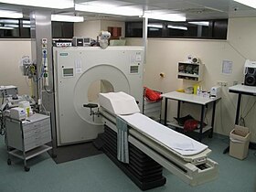
PET is both a medical and research tool. It is used heavily in clinical oncology (medical imaging of tumors and the search for metastases), and for clinical diagnosis of certain diffuse brain diseases such as those causing various types of dementias. PET is also an important research tool to map normal human brain and heart function, and support drug development.
PET is also used in pre-clinical studies using animals, where it allows repeated investigations into the same subjects. This is particularly valuable in cancer research, as it results in an increase in the statistical quality of the data (subjects can act as their own control) and substantially reduces the numbers of animals required for a given study.
Alternative methods of scanning include x-ray computed tomography (CT), magnetic resonance imaging (MRI) and functional magnetic resonance imaging (fMRI), ultrasound and single-photon emission computed tomography (SPECT).
While some imaging scans such as CT and MRI isolate organic anatomic changes in the body, PET and SPECT are capable of detecting areas of molecular biology detail (even prior to anatomic change). PET scanning does this using radiolabelled molecular probes that have different rates of uptake depending on the type and function of tissue involved. Changing of regional blood flow in various anatomic structures (as a measure of the injected positron emitter) can be visualized and relatively quantified with a PET scan.
PET imaging is best performed using a dedicated PET scanner. However, it is possible to acquire PET images using a conventional dual-head gamma camera fitted with a coincidence detector. The quality of gamma-camera PET is considerably lower, and acquisition is slower. However, for institutions with low demand for PET, this may allow on-site imaging, instead of referring patients to another center, or relying on a visit by a mobile scanner.
PET is a valuable technique for some diseases and disorders, because it is possible to target the radio-chemicals used for particular bodily functions.
A few other isotopes and radiotracers are slowly being introduced into oncology for specific purposes. For example, 11C-labelled metomidate (11C-metomidate), has been used to detect tumors of adrenocortical origin.[4][5] Also, FDOPA PET-CT, in centers which offer it, has proven to be a more sensitive alternative to finding, and also localizing, pheochromocytoma than the MIBG scan.[6][7][8]
Recently, three different PET contrast agents have been developed to image bacterial infections in vivo: [18F]maltose,[18] [18F]maltohexaose and [18F]2-fluorodeoxysorbitol (FDS).[19] FDS has also the added benefit of being able to target only Enterobacteriaceae.
The following is an excerpt from an article by Harvard University staff writer Peter Reuell, featured in HarvardScience, part of the online version of the Harvard Gazette newspaper, which discusses research by the team of Harvard Associate Professor of Organic Chemistry and Chemical Biology Tobias Ritter: "A new chemical process ... may increase the utility of positron emission tomography (PET) in creating real-time 3-D images of chemical activity occurring inside the body. This new work ... holds out the tantalizing possibility of using PET scans to peer into a number of functions inside animals and humans by simplifying the process of using “tracer” molecules to create the 3-D images." (by creating a novel electrophilic fluorination reagent as an intermediate molecule; the research could be used in drug development).[20]
18F-FDG, which is now the standard radiotracer used for PET neuroimaging and cancer patient management,[23] has an effective radiation dose of 14 mSv.[3]
The amount of radiation in 18F-FDG is similar to the effective dose of spending one year in the American city of Denver, Colorado (12.4 mSv/year).[24] For comparison, radiation dosage for other medical procedures range from 0.02 mSv for a chest x-ray and 6.5–8 mSv for a CT scan of the chest.[25][26] Average civil aircrews are exposed to 3 mSv/year,[27] and the whole body occupational dose limit for nuclear energy workers in the USA is 50mSv/year.[28] For scale, see Orders of magnitude (radiation).
For PET-CT scanning, the radiation exposure may be substantial—around 23–26 mSv (for a 70 kg person—dose is likely to be higher for higher body weights).[29]
Due to the short half-lives of most positron-emitting radioisotopes, the radiotracers have traditionally been produced using a cyclotron in close proximity to the PET imaging facility. The half-life of fluorine-18 is long enough that radiotracers labeled with fluorine-18 can be manufactured commercially at offsite locations and shipped to imaging centers. Recently rubidium-82 generators have become commercially available.[30] These contain strontium-82, which decays by electron capture to produce positron-emitting rubidium-82.
As the radioisotope undergoes positron emission decay (also known as positive beta decay), it emits a positron, an antiparticle of the electron with opposite charge. The emitted positron travels in tissue for a short distance (typically less than 1 mm, but dependent on the isotope[31]), during which time it loses kinetic energy, until it decelerates to a point where it can interact with an electron.[32] The encounter annihilates both electron and positron, producing a pair of annihilation (gamma) photons moving in approximately opposite directions. These are detected when they reach a scintillator in the scanning device, creating a burst of light which is detected by photomultiplier tubes or silicon avalanche photodiodes (Si APD). The technique depends on simultaneous or coincident detection of the pair of photons moving in approximately opposite directions (they would be exactly opposite in their center of mass frame, but the scanner has no way to know this, and so has a built-in slight direction-error tolerance). Photons that do not arrive in temporal "pairs" (i.e. within a timing-window of a few nanoseconds) are ignored.
Analytical techniques, much like the reconstruction of computed tomography (CT) and single-photon emission computed tomography (SPECT) data, are commonly used, although the data set collected in PET is much poorer than CT, so reconstruction techniques are more difficult. Coincidence events can be grouped into projection images, called sinograms. The sinograms are sorted by the angle of each view and tilt (for 3D images). The sinogram images are analogous to the projections captured by computed tomography (CT) scanners, and can be reconstructed in a similar way. However, the statistics of the data are much worse than those obtained through transmission tomography. A normal PET data set has millions of counts for the whole acquisition, while the CT can reach a few billion counts. This contributes to PET images appearing "noisier" than CT. Two major sources of noise in PET are scatter (a detected pair of photons, at least one of which was deflected from its original path by interaction with matter in the field of view, leading to the pair being assigned to an incorrect LOR) and random events (photons originating from two different annihilation events but incorrectly recorded as a coincidence pair because their arrival at their respective detectors occurred within a coincidence timing window).
In practice, considerable pre-processing of the data is required—correction for random coincidences, estimation and subtraction of scattered photons, detector dead-time correction (after the detection of a photon, the detector must "cool down" again) and detector-sensitivity correction (for both inherent detector sensitivity and changes in sensitivity due to angle of incidence).
Filtered back projection (FBP) has been frequently used to reconstruct images from the projections. This algorithm has the advantage of being simple while having a low requirement for computing resources. However, shot noise in the raw data is prominent in the reconstructed images and areas of high tracer uptake tend to form streaks across the image. Also, FBP treats the data deterministically—it does not account for the inherent randomness associated with PET data, thus requiring all the pre-reconstruction corrections described above.
Statistical, likelihood-based approaches: Statistical, likelihood-based [34] [35] iterative expectation-maximization algorithms such as the Shepp-Vardi algorithm[36] are now the preferred method of reconstruction. These algorithms compute an estimate of the likely distribution of annihilation events that led to the measured data, based on statistical principles. The advantage is a better noise profile and resistance to the streak artifacts common with FBP, but the disadvantage is higher computer resource requirements. A further advantage of statistical image reconstruction techniques is that the physical effects that would need to be pre-corrected for when using an analytical reconstruction algorithm, such as scattered photons, random coincidences, attenuation and detector dead-time, can be incorporated into the likelihood model being used in the reconstruction, allowing for additional noise reduction. Iterative reconstruction has also been shown to result in improvements in the resolution of the reconstructed images, since more sophisticated models of the scanner Physics can be incorporated into the likelihood model than those used by analytical reconstruction methods, allowing for improved quantification of the radioactivity distribution.[37]
Research has shown that Bayesian methods that involve a Poisson likelihood function and an appropriate prior probability (e.g., a smoothing prior leading to total variation regularization or a Laplacian distribution leading to -based regularization in a wavelet or other domain), such as via Ulf Grenander's Sieve estimator[38] [39] or via Bayes penalty methods [40] [41] or via I.J. Good's roughness method [42] ,[43] may yield superior performance to expectation-maximization-based methods which involve a Poisson likelihood function but do not involve such a prior.[44][45][46]
Attenuation correction: Attenuation occurs when photons emitted by the radiotracer inside the body are absorbed by intervening tissue between the detector and the emission of the photon. As different LORs must traverse different thicknesses of tissue, the photons are attenuated differentially. The result is that structures deep in the body are reconstructed as having falsely low tracer uptake. Contemporary scanners can estimate attenuation using integrated x-ray CT equipment, however earlier equipment offered a crude form of CT using a gamma ray (positron emitting) source and the PET detectors.
While attenuation-corrected images are generally more faithful representations, the correction process is itself susceptible to significant artifacts. As a result, both corrected and uncorrected images are always reconstructed and read together.
2D/3D reconstruction: Early PET scanners had only a single ring of detectors, hence the acquisition of data and subsequent reconstruction was restricted to a single transverse plane. More modern scanners now include multiple rings, essentially forming a cylinder of detectors.
There are two approaches to reconstructing data from such a scanner: 1) treat each ring as a separate entity, so that only coincidences within a ring are detected, the image from each ring can then be reconstructed individually (2D reconstruction), or 2) allow coincidences to be detected between rings as well as within rings, then reconstruct the entire volume together (3D).
3D techniques have better sensitivity (because more coincidences are detected and used) and therefore less noise, but are more sensitive to the effects of scatter and random coincidences, as well as requiring correspondingly greater computer resources. The advent of sub-nanosecond timing resolution detectors affords better random coincidence rejection, thus favoring 3D image reconstruction.
Time-of-flight (TOF) PET: For modern systems with a higher time resolution (roughly 3 nanoseconds) a technique called "Time-of-flight" is used to improve the overall performance. Time-of-flight PET makes use of very fast gamma-ray detectors and data processing system which can more precisely decide the difference in time between the detection of the two photons. Although it is technically impossible to localize the point of origin of the annihilation event exactly (currently within 10 cm) thus image reconstruction is still needed, TOF technique gives a remarkable improvement in image quality, especially signal-to-noise ratio.
At the Jülich Institute of Neurosciences and Biophysics, the world's largest PET-MRI device began operation in April 2009: a 9.4-tesla magnetic resonance tomograph (MRT) combined with a positron emission tomograph (PET). Presently, only the head and brain can be imaged at these high magnetic field strengths.[47]
For brain imaging, registration of CT, MRI and PET scans may be accomplished without the need for an integrated PET-CT or PET-MRI scanner by using a device known as the N-localizer.
Limitations to the widespread use of PET arise from the high costs of cyclotrons needed to produce the short-lived radionuclides for PET scanning and the need for specially adapted on-site chemical synthesis apparatus to produce the radiopharmaceuticals after radioisotope preparation. Organic radiotracer molecules that will contain a positron-emitting radioisotope cannot be synthesized first and then the radioisotope prepared within them, because bombardment with a cyclotron to prepare the radioisotope destroys any organic carrier for it. Instead, the isotope must be prepared first, then afterward, the chemistry to prepare any organic radiotracer (such as FDG) accomplished very quickly, in the short time before the isotope decays. Few hospitals and universities are capable of maintaining such systems, and most clinical PET is supported by third-party suppliers of radiotracers that can supply many sites simultaneously. This limitation restricts clinical PET primarily to the use of tracers labelled with fluorine-18, which has a half-life of 110 minutes and can be transported a reasonable distance before use, or to rubidium-82 (used as rubidium-82 chloride) with a half-life of 1.27 minutes, which is created in a portable generator and is used for myocardial perfusion studies. Nevertheless, in recent years a few on-site cyclotrons with integrated shielding and "hot labs" (automated chemistry labs that are able to work with radioisotopes) have begun to accompany PET units to remote hospitals. The presence of the small on-site cyclotron promises to expand in the future as the cyclotrons shrink in response to the high cost of isotope transportation to remote PET machines.[65] In recent years the shortage of PET scans has been alleviated in the US, as rollout of radiopharmacies to supply radioisotopes has grown 30%/year.[66]
Because the half-life of fluorine-18 is about two hours, the prepared dose of a radiopharmaceutical bearing this radionuclide will undergo multiple half-lives of decay during the working day. This necessitates frequent recalibration of the remaining dose (determination of activity per unit volume) and careful planning with respect to patient scheduling.
Work by Gordon Brownell, Charles Burnham and their associates at the Massachusetts General Hospital beginning in the 1950s contributed significantly to the development of PET technology and included the first demonstration of annihilation radiation for medical imaging.[69] Their innovations, including the use of light pipes and volumetric analysis, have been important in the deployment of PET imaging. In 1961, James Robertson and his associates at Brookhaven National Laboratory built the first single-plane PET scan, nicknamed the "head-shrinker."[70]
One of the factors most responsible for the acceptance of positron imaging was the development of radiopharmaceuticals. In particular, the development of labeled 2-fluorodeoxy-D-glucose (2FDG) by the Brookhaven group under the direction of Al Wolf and Joanna Fowler was a major factor in expanding the scope of PET imaging.[71] The compound was first administered to two normal human volunteers by Abass Alavi in August 1976 at the University of Pennsylvania. Brain images obtained with an ordinary (non-PET) nuclear scanner demonstrated the concentration of FDG in that organ. Later, the substance was used in dedicated positron tomographic scanners, to yield the modern procedure.
The logical extension of positron instrumentation was a design using two 2-dimensional arrays. PC-I was the first instrument using this concept and was designed in 1968, completed in 1969 and reported in 1972. The first applications of PC-I in tomographic mode as distinguished from the computed tomographic mode were reported in 1970.[72] It soon became clear to many of those involved in PET development that a circular or cylindrical array of detectors was the logical next step in PET instrumentation. Although many investigators took this approach, James Robertson[73] and Zang-Hee Cho[74] were the first to propose a ring system that has become the prototype of the current shape of PET.
The PET-CT scanner, attributed to Dr. David Townsend and Dr. Ronald Nutt, was named by TIME Magazine as the medical invention of the year in 2000.[75]
In England, the NHS reference cost (2015-2016) for an adult outpatient PET scan is £798, and £242 for direct access services.[77]
If the biologically active molecule chosen for PET is fludeoxyglucose (FDG), an analogue of glucose, the concentrations of tracer imaged will indicate tissue metabolic activity as it corresponds to the regional glucose uptake. Use of this tracer to explore the possibility of cancer metastasis (i.e., spreading to other sites) is the most common type of PET scan in standard medical care (90% of current scans). However, although on a minority basis, many other radioactive tracers are used in PET to image the tissue concentration of other types of molecules of interest. One of the disadvantages of PET scanners is their operating cost .

Uses


PET is also used in pre-clinical studies using animals, where it allows repeated investigations into the same subjects. This is particularly valuable in cancer research, as it results in an increase in the statistical quality of the data (subjects can act as their own control) and substantially reduces the numbers of animals required for a given study.
Alternative methods of scanning include x-ray computed tomography (CT), magnetic resonance imaging (MRI) and functional magnetic resonance imaging (fMRI), ultrasound and single-photon emission computed tomography (SPECT).
While some imaging scans such as CT and MRI isolate organic anatomic changes in the body, PET and SPECT are capable of detecting areas of molecular biology detail (even prior to anatomic change). PET scanning does this using radiolabelled molecular probes that have different rates of uptake depending on the type and function of tissue involved. Changing of regional blood flow in various anatomic structures (as a measure of the injected positron emitter) can be visualized and relatively quantified with a PET scan.
PET imaging is best performed using a dedicated PET scanner. However, it is possible to acquire PET images using a conventional dual-head gamma camera fitted with a coincidence detector. The quality of gamma-camera PET is considerably lower, and acquisition is slower. However, for institutions with low demand for PET, this may allow on-site imaging, instead of referring patients to another center, or relying on a visit by a mobile scanner.
PET is a valuable technique for some diseases and disorders, because it is possible to target the radio-chemicals used for particular bodily functions.
Oncology
PET scanning with the tracer fluorine-18 (F-18) fluorodeoxyglucose (FDG), called FDG-PET, is widely used in clinical oncology. This tracer is a glucose analog that is taken up by glucose-using cells and phosphorylated by hexokinase (whose mitochondrial form is greatly elevated in rapidly growing malignant tumors). A typical dose of FDG used in an oncological scan has an effective radiation dose of 14 mSv.[3] Because the oxygen atom that is replaced by F-18 to generate FDG is required for the next step in glucose metabolism in all cells, no further reactions occur in FDG. Furthermore, most tissues (with the notable exception of liver and kidneys) cannot remove the phosphate added by hexokinase. This means that FDG is trapped in any cell that takes it up, until it decays, since phosphorylated sugars, due to their ionic charge, cannot exit from the cell. This results in intense radiolabeling of tissues with high glucose uptake, such as the brain, the liver, and most cancers. As a result, FDG-PET can be used for diagnosis, staging, and monitoring treatment of cancers, particularly in Hodgkin's lymphoma, non-Hodgkin lymphoma, and lung cancer.[citation needed]A few other isotopes and radiotracers are slowly being introduced into oncology for specific purposes. For example, 11C-labelled metomidate (11C-metomidate), has been used to detect tumors of adrenocortical origin.[4][5] Also, FDOPA PET-CT, in centers which offer it, has proven to be a more sensitive alternative to finding, and also localizing, pheochromocytoma than the MIBG scan.[6][7][8]
Neuroimaging
- Neurology: PET neuroimaging is based on an assumption that areas of high radioactivity are associated with brain activity. What is actually measured indirectly is the flow of blood to different parts of the brain, which is, in general, believed to be correlated, and has been measured using the tracer oxygen-15. However, because of its 2-minute half-life, O-15 must be piped directly from a medical cyclotron for such uses, which is difficult. In practice, since the brain is normally a rapid user of glucose, and since brain pathologies such as Alzheimer's disease greatly decrease brain metabolism of both glucose and oxygen in tandem, standard FDG-PET of the brain, which measures regional glucose use, may also be successfully used to differentiate Alzheimer's disease from other dementing processes, and also to make early diagnosis of Alzheimer's disease. The advantage of FDG-PET for these uses is its much wider availability. PET imaging with FDG can also be used for localization of seizure focus: A seizure focus will appear as hypometabolic during an interictal scan. Several radiotracers (i.e. radioligands) have been developed for PET that are ligands for specific neuroreceptor subtypes such as [11C] raclopride, [18F] fallypride and [18F] desmethoxyfallypride for dopamine D2/D3 receptors, [11C] McN 5652 and [11C] DASB for serotonin transporters, [18F] Mefway for serotonin 5HT1A receptors, [18F] Nifene for nicotinic acetylcholine receptors or enzyme substrates (e.g. 6-FDOPA for the AADC enzyme). These agents permit the visualization of neuroreceptor pools in the context of a plurality of neuropsychiatric and neurologic illnesses.
 PET scan of the human brain.

- Neuropsychology / Cognitive neuroscience: To examine links between specific psychological processes or disorders and brain activity.
- Psychiatry: Numerous compounds that bind selectively to neuroreceptors of interest in biological psychiatry have been radiolabeled with C-11 or F-18. Radioligands that bind to dopamine receptors (D1,[13] D2 receptor,[14][15] reuptake transporter), serotonin receptors (5HT1A, 5HT2A, reuptake transporter) opioid receptors (mu) and other sites have been used successfully in studies with human subjects. Studies have been performed examining the state of these receptors in patients compared to healthy controls in schizophrenia, substance abuse, mood disorders and other psychiatric conditions.
- Stereotactic surgery and radiosurgery: PET-image guided surgery facilitates treatment of intracranial tumors, arteriovenous malformations and other surgically treatable conditions.[16]
Cardiology
Cardiology, atherosclerosis and vascular disease study: In clinical cardiology, FDG-PET can identify so-called "hibernating myocardium", but its cost-effectiveness in this role versus SPECT is unclear. FDG-PET imaging of atherosclerosis to detect patients at risk of stroke is also feasible and can help test the efficacy of novel anti-atherosclerosis therapies.[17]Infectious diseases
Imaging infections with molecular imaging technologies can improve diagnosis and treatment follow-up. PET has been widely used to image bacterial infections clinically by using fluorodeoxyglucose (FDG) to identify the infection-associated inflammatory response.Recently, three different PET contrast agents have been developed to image bacterial infections in vivo: [18F]maltose,[18] [18F]maltohexaose and [18F]2-fluorodeoxysorbitol (FDS).[19] FDS has also the added benefit of being able to target only Enterobacteriaceae.
Pharmacokinetics
Pharmacokinetics: In pre-clinical trials, it is possible to radiolabel a new drug and inject it into animals. Such scans are referred to as biodistribution studies. The uptake of the drug, the tissues in which it concentrates, and its eventual elimination, can be monitored far more quickly and cost effectively than the older technique of killing and dissecting the animals to discover the same information. Much more commonly, however, drug occupancy at a purported site of action can be inferred indirectly by competition studies between unlabeled drug and radiolabeled compounds known apriori to bind with specificity to the site. A single radioligand can be used this way to test many potential drug candidates for the same target. A related technique involves scanning with radioligands that compete with an endogenous (naturally occurring) substance at a given receptor to demonstrate that a drug causes the release of the natural substance.[citation needed]The following is an excerpt from an article by Harvard University staff writer Peter Reuell, featured in HarvardScience, part of the online version of the Harvard Gazette newspaper, which discusses research by the team of Harvard Associate Professor of Organic Chemistry and Chemical Biology Tobias Ritter: "A new chemical process ... may increase the utility of positron emission tomography (PET) in creating real-time 3-D images of chemical activity occurring inside the body. This new work ... holds out the tantalizing possibility of using PET scans to peer into a number of functions inside animals and humans by simplifying the process of using “tracer” molecules to create the 3-D images." (by creating a novel electrophilic fluorination reagent as an intermediate molecule; the research could be used in drug development).[20]
Small animal imaging
PET technology for small animal imaging: A miniature PE tomograph has been constructed that is small enough for a fully conscious and mobile rat to wear on its head while walking around.[21] This RatCAP (Rat Conscious Animal PET) allows animals to be scanned without the confounding effects of anesthesia. PET scanners designed specifically for imaging rodents, often referred to as microPET, as well as scanners for small primates are marketed for academic and pharmaceutical research. The scanners are apparently based on microminiature scintillators and amplified avalanche photodiodes (APDs) though a new system recently invented uses single chip silicon photomultipliers.Musculo-skeletal imaging
Musculoskeletal imaging: PET has been shown to be a feasible technique for studying skeletal muscles during exercises like walking.[22] One of the main advantages of using PET is that it can also provide muscle activation data about deeper lying muscles such as the vastus intermedialis and the gluteus minimus, as compared to other muscle studying techniques like electromyography, which can be used only on superficial muscles (i.e., directly under the skin). A clear disadvantage, however, is that PET provides no timing information about muscle activation, because it has to be measured after the exercise is completed. This is due to the time it takes for FDG to accumulate in the activated muscles.Safety
PET scanning is non-invasive, but it does involve exposure to ionizing radiation.[2]18F-FDG, which is now the standard radiotracer used for PET neuroimaging and cancer patient management,[23] has an effective radiation dose of 14 mSv.[3]
The amount of radiation in 18F-FDG is similar to the effective dose of spending one year in the American city of Denver, Colorado (12.4 mSv/year).[24] For comparison, radiation dosage for other medical procedures range from 0.02 mSv for a chest x-ray and 6.5–8 mSv for a CT scan of the chest.[25][26] Average civil aircrews are exposed to 3 mSv/year,[27] and the whole body occupational dose limit for nuclear energy workers in the USA is 50mSv/year.[28] For scale, see Orders of magnitude (radiation).
For PET-CT scanning, the radiation exposure may be substantial—around 23–26 mSv (for a 70 kg person—dose is likely to be higher for higher body weights).[29]
Operation

Radionuclides and radiotracers
Radionuclides used in PET scanning are typically isotopes with short half-lives [2] such as carbon-11 (~20 min), nitrogen-13 (~10 min), oxygen-15 (~2 min), fluorine-18 (~110 min), gallium-68 (~67 min), zirconium-89 (~78.41 hours), or rubidium-82(~1.27 min). These radionuclides are incorporated either into compounds normally used by the body such as glucose (or glucose analogues), water, or ammonia, or into molecules that bind to receptors or other sites of drug action. Such labelled compounds are known as radiotracers. PET technology can be used to trace the biologic pathway of any compound in living humans (and many other species as well), provided it can be radiolabeled with a PET isotope. Thus, the specific processes that can be probed with PET are virtually limitless, and radiotracers for new target molecules and processes are continuing to be synthesized; as of this writing there are already dozens in clinical use and hundreds applied in research. At present, however, by far the most commonly used radiotracer in clinical PET scanning is fluorodeoxyglucose (also called FDG or fludeoxyglucose), an analogue of glucose that is labeled with fluorine-18. This radiotracer is used in essentially all scans for oncology and most scans in neurology, and thus makes up the large majority of all of the radiotracer (> 95%) used in PET and PET-CT scanning.Due to the short half-lives of most positron-emitting radioisotopes, the radiotracers have traditionally been produced using a cyclotron in close proximity to the PET imaging facility. The half-life of fluorine-18 is long enough that radiotracers labeled with fluorine-18 can be manufactured commercially at offsite locations and shipped to imaging centers. Recently rubidium-82 generators have become commercially available.[30] These contain strontium-82, which decays by electron capture to produce positron-emitting rubidium-82.
Emission
To conduct the scan, a short-lived radioactive tracer isotope is injected into the living subject (usually into blood circulation). Each tracer atom has been chemically incorporated into a biologically active molecule. There is a waiting period while the active molecule becomes concentrated in tissues of interest; then the subject is placed in the imaging scanner. The molecule most commonly used for this purpose is F-18 labeled fluorodeoxyglucose (FDG), a sugar, for which the waiting period is typically an hour. During the scan, a record of tissue concentration is made as the tracer decays.As the radioisotope undergoes positron emission decay (also known as positive beta decay), it emits a positron, an antiparticle of the electron with opposite charge. The emitted positron travels in tissue for a short distance (typically less than 1 mm, but dependent on the isotope[31]), during which time it loses kinetic energy, until it decelerates to a point where it can interact with an electron.[32] The encounter annihilates both electron and positron, producing a pair of annihilation (gamma) photons moving in approximately opposite directions. These are detected when they reach a scintillator in the scanning device, creating a burst of light which is detected by photomultiplier tubes or silicon avalanche photodiodes (Si APD). The technique depends on simultaneous or coincident detection of the pair of photons moving in approximately opposite directions (they would be exactly opposite in their center of mass frame, but the scanner has no way to know this, and so has a built-in slight direction-error tolerance). Photons that do not arrive in temporal "pairs" (i.e. within a timing-window of a few nanoseconds) are ignored.

Localization of the positron annihilation event
The most significant fraction of electron–positron annihilations results in two 511 keV gamma photons being emitted at almost 180 degrees to each other; hence, it is possible to localize their source along a straight line of coincidence (also called the line of response, or LOR). In practice, the LOR has a non-zero width as the emitted photons are not exactly 180 degrees apart. If the resolving time of the detectors is less than 500 picoseconds rather than about 10 nanoseconds, it is possible to localize the event to a segment of a chord, whose length is determined by the detector timing resolution. As the timing resolution improves, the signal-to-noise ratio (SNR) of the image will improve, requiring fewer events to achieve the same image quality. This technology is not yet common, but it is available on some new systems.[33]Image reconstruction
The raw data collected by a PET scanner are a list of 'coincidence events' representing near-simultaneous detection (typically, within a window of 6 to 12 nanoseconds of each other) of annihilation photons by a pair of detectors. Each coincidence event represents a line in space connecting the two detectors along which the positron emission occurred (i.e., the line of response (LOR)).Analytical techniques, much like the reconstruction of computed tomography (CT) and single-photon emission computed tomography (SPECT) data, are commonly used, although the data set collected in PET is much poorer than CT, so reconstruction techniques are more difficult. Coincidence events can be grouped into projection images, called sinograms. The sinograms are sorted by the angle of each view and tilt (for 3D images). The sinogram images are analogous to the projections captured by computed tomography (CT) scanners, and can be reconstructed in a similar way. However, the statistics of the data are much worse than those obtained through transmission tomography. A normal PET data set has millions of counts for the whole acquisition, while the CT can reach a few billion counts. This contributes to PET images appearing "noisier" than CT. Two major sources of noise in PET are scatter (a detected pair of photons, at least one of which was deflected from its original path by interaction with matter in the field of view, leading to the pair being assigned to an incorrect LOR) and random events (photons originating from two different annihilation events but incorrectly recorded as a coincidence pair because their arrival at their respective detectors occurred within a coincidence timing window).
In practice, considerable pre-processing of the data is required—correction for random coincidences, estimation and subtraction of scattered photons, detector dead-time correction (after the detection of a photon, the detector must "cool down" again) and detector-sensitivity correction (for both inherent detector sensitivity and changes in sensitivity due to angle of incidence).
Filtered back projection (FBP) has been frequently used to reconstruct images from the projections. This algorithm has the advantage of being simple while having a low requirement for computing resources. However, shot noise in the raw data is prominent in the reconstructed images and areas of high tracer uptake tend to form streaks across the image. Also, FBP treats the data deterministically—it does not account for the inherent randomness associated with PET data, thus requiring all the pre-reconstruction corrections described above.
Statistical, likelihood-based approaches: Statistical, likelihood-based [34] [35] iterative expectation-maximization algorithms such as the Shepp-Vardi algorithm[36] are now the preferred method of reconstruction. These algorithms compute an estimate of the likely distribution of annihilation events that led to the measured data, based on statistical principles. The advantage is a better noise profile and resistance to the streak artifacts common with FBP, but the disadvantage is higher computer resource requirements. A further advantage of statistical image reconstruction techniques is that the physical effects that would need to be pre-corrected for when using an analytical reconstruction algorithm, such as scattered photons, random coincidences, attenuation and detector dead-time, can be incorporated into the likelihood model being used in the reconstruction, allowing for additional noise reduction. Iterative reconstruction has also been shown to result in improvements in the resolution of the reconstructed images, since more sophisticated models of the scanner Physics can be incorporated into the likelihood model than those used by analytical reconstruction methods, allowing for improved quantification of the radioactivity distribution.[37]
Research has shown that Bayesian methods that involve a Poisson likelihood function and an appropriate prior probability (e.g., a smoothing prior leading to total variation regularization or a Laplacian distribution leading to -based regularization in a wavelet or other domain), such as via Ulf Grenander's Sieve estimator[38] [39] or via Bayes penalty methods [40] [41] or via I.J. Good's roughness method [42] ,[43] may yield superior performance to expectation-maximization-based methods which involve a Poisson likelihood function but do not involve such a prior.[44][45][46]

Attenuation correction: Attenuation occurs when photons emitted by the radiotracer inside the body are absorbed by intervening tissue between the detector and the emission of the photon. As different LORs must traverse different thicknesses of tissue, the photons are attenuated differentially. The result is that structures deep in the body are reconstructed as having falsely low tracer uptake. Contemporary scanners can estimate attenuation using integrated x-ray CT equipment, however earlier equipment offered a crude form of CT using a gamma ray (positron emitting) source and the PET detectors.
While attenuation-corrected images are generally more faithful representations, the correction process is itself susceptible to significant artifacts. As a result, both corrected and uncorrected images are always reconstructed and read together.
2D/3D reconstruction: Early PET scanners had only a single ring of detectors, hence the acquisition of data and subsequent reconstruction was restricted to a single transverse plane. More modern scanners now include multiple rings, essentially forming a cylinder of detectors.
There are two approaches to reconstructing data from such a scanner: 1) treat each ring as a separate entity, so that only coincidences within a ring are detected, the image from each ring can then be reconstructed individually (2D reconstruction), or 2) allow coincidences to be detected between rings as well as within rings, then reconstruct the entire volume together (3D).
3D techniques have better sensitivity (because more coincidences are detected and used) and therefore less noise, but are more sensitive to the effects of scatter and random coincidences, as well as requiring correspondingly greater computer resources. The advent of sub-nanosecond timing resolution detectors affords better random coincidence rejection, thus favoring 3D image reconstruction.
Time-of-flight (TOF) PET: For modern systems with a higher time resolution (roughly 3 nanoseconds) a technique called "Time-of-flight" is used to improve the overall performance. Time-of-flight PET makes use of very fast gamma-ray detectors and data processing system which can more precisely decide the difference in time between the detection of the two photons. Although it is technically impossible to localize the point of origin of the annihilation event exactly (currently within 10 cm) thus image reconstruction is still needed, TOF technique gives a remarkable improvement in image quality, especially signal-to-noise ratio.


Combination of PET with CT or MRI[
PET scans are increasingly read alongside CT or magnetic resonance imaging (MRI) scans, with the combination (called "co-registration") giving both anatomic and metabolic information (i.e., what the structure is, and what it is doing biochemically). Because PET imaging is most useful in combination with anatomical imaging, such as CT, modern PET scanners are now available with integrated high-end multi-detector-row CT scanners (so-called "PET-CT"). Because the two scans can be performed in immediate sequence during the same session, with the patient not changing position between the two types of scans, the two sets of images are more precisely registered, so that areas of abnormality on the PET imaging can be more perfectly correlated with anatomy on the CT images. This is very useful in showing detailed views of moving organs or structures with higher anatomical variation, which is more common outside the brain.At the Jülich Institute of Neurosciences and Biophysics, the world's largest PET-MRI device began operation in April 2009: a 9.4-tesla magnetic resonance tomograph (MRT) combined with a positron emission tomograph (PET). Presently, only the head and brain can be imaged at these high magnetic field strengths.[47]
For brain imaging, registration of CT, MRI and PET scans may be accomplished without the need for an integrated PET-CT or PET-MRI scanner by using a device known as the N-localizer.
Limitations
The minimization of radiation dose to the subject is an attractive feature of the use of short-lived radionuclides. Besides its established role as a diagnostic technique, PET has an expanding role as a method to assess the response to therapy, in particular, cancer therapy,[64] where the risk to the patient from lack of knowledge about disease progress is much greater than the risk from the test radiation.Limitations to the widespread use of PET arise from the high costs of cyclotrons needed to produce the short-lived radionuclides for PET scanning and the need for specially adapted on-site chemical synthesis apparatus to produce the radiopharmaceuticals after radioisotope preparation. Organic radiotracer molecules that will contain a positron-emitting radioisotope cannot be synthesized first and then the radioisotope prepared within them, because bombardment with a cyclotron to prepare the radioisotope destroys any organic carrier for it. Instead, the isotope must be prepared first, then afterward, the chemistry to prepare any organic radiotracer (such as FDG) accomplished very quickly, in the short time before the isotope decays. Few hospitals and universities are capable of maintaining such systems, and most clinical PET is supported by third-party suppliers of radiotracers that can supply many sites simultaneously. This limitation restricts clinical PET primarily to the use of tracers labelled with fluorine-18, which has a half-life of 110 minutes and can be transported a reasonable distance before use, or to rubidium-82 (used as rubidium-82 chloride) with a half-life of 1.27 minutes, which is created in a portable generator and is used for myocardial perfusion studies. Nevertheless, in recent years a few on-site cyclotrons with integrated shielding and "hot labs" (automated chemistry labs that are able to work with radioisotopes) have begun to accompany PET units to remote hospitals. The presence of the small on-site cyclotron promises to expand in the future as the cyclotrons shrink in response to the high cost of isotope transportation to remote PET machines.[65] In recent years the shortage of PET scans has been alleviated in the US, as rollout of radiopharmacies to supply radioisotopes has grown 30%/year.[66]
Because the half-life of fluorine-18 is about two hours, the prepared dose of a radiopharmaceutical bearing this radionuclide will undergo multiple half-lives of decay during the working day. This necessitates frequent recalibration of the remaining dose (determination of activity per unit volume) and careful planning with respect to patient scheduling.
The concept of emission and transmission tomography was introduced by David E. Kuhl, Luke Chapman and Roy Edwards in the late 1950s. Their work later led to the design and construction of several tomographic instruments at the University of Pennsylvania. In 1975 tomographic imaging techniques were further developed by Michel Ter-Pogossian, Michael E. Phelps, Edward J. Hoffman and others at Washington University School of Medicine.[67][68]
Work by Gordon Brownell, Charles Burnham and their associates at the Massachusetts General Hospital beginning in the 1950s contributed significantly to the development of PET technology and included the first demonstration of annihilation radiation for medical imaging.[69] Their innovations, including the use of light pipes and volumetric analysis, have been important in the deployment of PET imaging. In 1961, James Robertson and his associates at Brookhaven National Laboratory built the first single-plane PET scan, nicknamed the "head-shrinker."[70]
One of the factors most responsible for the acceptance of positron imaging was the development of radiopharmaceuticals. In particular, the development of labeled 2-fluorodeoxy-D-glucose (2FDG) by the Brookhaven group under the direction of Al Wolf and Joanna Fowler was a major factor in expanding the scope of PET imaging.[71] The compound was first administered to two normal human volunteers by Abass Alavi in August 1976 at the University of Pennsylvania. Brain images obtained with an ordinary (non-PET) nuclear scanner demonstrated the concentration of FDG in that organ. Later, the substance was used in dedicated positron tomographic scanners, to yield the modern procedure.
The logical extension of positron instrumentation was a design using two 2-dimensional arrays. PC-I was the first instrument using this concept and was designed in 1968, completed in 1969 and reported in 1972. The first applications of PC-I in tomographic mode as distinguished from the computed tomographic mode were reported in 1970.[72] It soon became clear to many of those involved in PET development that a circular or cylindrical array of detectors was the logical next step in PET instrumentation. Although many investigators took this approach, James Robertson[73] and Zang-Hee Cho[74] were the first to propose a ring system that has become the prototype of the current shape of PET.
The PET-CT scanner, attributed to Dr. David Townsend and Dr. Ronald Nutt, was named by TIME Magazine as the medical invention of the year in 2000.[75]
Cost
As of August 2008, Cancer Care Ontario reports that the current average incremental cost to perform a PET scan in the province is Can$1,000–1,200 per scan. This includes the cost of the radiopharmaceutical and a stipend for the physician reading the scan.[76]In England, the NHS reference cost (2015-2016) for an adult outpatient PET scan is £798, and £242 for direct access services.[77]
Quality Control
The overall performance of PET systems can be evaluated by quality control tools such as the Jaszczak phantom.compare :
- Diffuse optical imaging
- Hot cell (Equipment used to produce the radiopharmaceuticals used in PET)
- Molecular Imaging
- PET radiotracer
- CT Scan

Class-D amplifier
A class-D amplifier or switching amplifier is an electronic amplifier in which the amplifying devices (transistors, usually MOSFETs) operate as electronic switches, and not as linear gain devices as in other amplifiers. They are rapidly switching back and forth between the supply rails, being fed by a modulator using pulse width, pulse density, or related techniques to encode the audio input into a pulse train. The audio escapes through a simple low-pass filter into the loudspeaker. The high-frequency pulses, which can be as high as 6 MHz, are blocked. Since the pairs of output transistors are never conducting at the same time, there is no other path for current flow apart from the low-pass filter/loudspeaker. For this reason, efficiency can exceed 90%.

Block diagram of a basic switching or PWM (class-D) amplifier.
Note: For clarity, signal periods are not shown to scale.
Note: For clarity, signal periods are not shown to scale.
Basic operation
Class-D amplifiers work by generating a train of square pulses of fixed amplitude but varying width and separation, or varying number per unit time, representing the amplitude variations of the analog audio input signal. It is also possible to synchronize the modulator clock with an incoming digital audio signal, thus removing the necessity to convert it to analog, The output of the modulator is then used to gate the output transistors on and off alternately. Great care is taken to ensure that the pair of transistors are never allowed to conduct together. This would cause a short circuit between the supply rails through the transistors. Since the transistors are either fully "on" or fully "off", they spend very little time in the linear region, and dissipate very little power. This is the main reason for their high efficiency. A simple low-pass filter consisting of an inductor and a capacitor are used to provide a path for the low-frequencies of the audio signal, leaving the high-frequency pulses behind. In cost sensitive applications the output filter is sometimes omitted. The circuit then relies on the inductance of the loudspeaker to keep the HF component from heating up the voice coil.The structure of a class-D power stage is somewhat comparable to that of a synchronously rectified buck converter (a type of non-isolated switched-mode power supply (SMPS)), but works backwards. Whereas buck converters usually function as voltage regulators, delivering a constant DC voltage into a variable load and can only source current (one-quadrant operation), a class-D amplifier delivers a constantly changing voltage into a fixed load, where current and voltage can independently change sign (four-quadrant operation). A switching amplifier must not be confused with linear amplifiers that use an SMPS as their source of DC power. A switching amplifier may use any type of power supply (e.g., a car battery or an internal SMPS), but the defining characteristic is that the amplification process itself operates by switching. Unlike a SMPS, the amplifier has a much more critical job to do, to keep unwanted artifacts out of the output. Feedback is almost always used, for the same reasons as in traditional analog amplifiers, to reduce noise and distortion.
Theoretical power efficiency of class-D amplifiers is 100%. That is to say, all of the power supplied to it is delivered to the load, none is turned to heat. This is because an ideal switch in its on state would conduct all the current but have no voltage loss across it, hence no heat would be dissipated. And when it is off, it would have the full supply voltage across it but no leak current flowing through it, and again no heat would be dissipated. Real-world power MOSFETs are not ideal switches, but practical efficiencies well over 90% are common. By contrast, linear AB-class amplifiers are always operated with both current flowing through and voltage standing across the power devices. An ideal class-B amplifier has a theoretical maximum efficiency of 78%. Class A amplifiers (purely linear, with the devices always "on") have a theoretical maximum efficiency of 50% and some versions have efficiencies below 20%.
Terminology
The term "class D" is sometimes misunderstood as meaning a "digital" amplifier. While some class-D amps may indeed be controlled by digital circuits or include digital signal processing devices, the power stage deals with voltage and current as a function of non-quantized time. The smallest amount of noise, timing uncertainty, voltage ripple or any other non-ideality immediately results in an irreversible change of the output signal. The same errors in a digital system will only lead to incorrect results when they become so large that a signal representing a digit is distorted beyond recognition. Up to that point, non-idealities have no impact on the transmitted signal. Generally, digital signals are quantized in both amplitude and wavelength, while analog signals are quantized in one (e.g. PWM) or (usually) neither quantity.Signal modulation
The 2-level waveform is derived using pulse-width modulation (PWM), pulse density modulation (sometimes referred to as pulse frequency modulation), sliding mode control (more commonly called "self-oscillating modulation" in the trade.[1]) or discrete-time forms of modulation such as delta-sigma modulation.[2]The most basic way of creating the PWM signal is to use a high speed comparator ("C" in the block-diagram above) that compares a high frequency triangular wave with the audio input. This generates a series of pulses of which the duty cycle is directly proportional with the instantaneous value of the audio signal. The comparator then drives a MOS gate driver which in turn drives a pair of high-power switches (usually MOSFETs). This produces an amplified replica of the comparator's PWM signal. The output filter removes the high-frequency switching components of the PWM signal and recovers the audio information that the speaker can use.
DSP-based amplifiers which generate a PWM signal directly from a digital audio signal (e. g. SPDIF) either use a counter to time the pulse length[3] or implement a digital equivalent of a triangle-based modulator. In either case, the time resolution afforded by practical clock frequencies is only a few hundredths of a switching period, which is not enough to ensure low noise. In effect, the pulse length gets quantized, resulting in quantization distortion. In both cases, negative feedback is applied inside the digital domain, forming a noise shaper which has lower noise in the audible frequency range.
Design challenges
Switching speed
Two significant design challenges for MOSFET driver circuits in class-D amplifiers are keeping dead times and linear mode operation as short as possible. "Dead time" is the period during a switching transition when both output MOSFETs are driven into Cut-Off Mode and both are "off". Dead times need to be as short as possible to maintain an accurate low-distortion output signal, but dead times that are too short cause the MOSFET that is switching on to start conducting before the MOSFET that is switching off has stopped conducting. The MOSFETs effectively short the output power supply through themselves in a condition known as "shoot-through". Meanwhile, the MOSFET drivers also need to drive the MOSFETs between switching states as fast as possible to minimize the amount of time a MOSFET is in Linear Mode—the state between Cut-Off Mode and Saturation Mode where the MOSFET is neither fully on nor fully off and conducts current with a significant resistance, creating significant heat. Driver failures that allow shoot-through and/or too much linear mode operation result in excessive losses and sometimes catastrophic failure of the MOSFETs.[4] There are also problems with using PWM for the modulator; as the audio level approaches 100%, the pulse width can get so narrow as to challenge the ability of the driver circuit and the MOSFET to respond. These pulses can get down to just a few nanoseconds and can result in the above undesired conditions of shoot-through and/or Linear mode. This is why other modulation techniques such as Pulse Density can get closer to the theoretical 100% efficiency than PWM.Electromagnetic interference
The switching power stage generates both high dV/dt and dI/dt, which give rise to radiated emission whenever any part of the circuit is large enough to act as an antenna. In practice, this means the connecting wires and cables will be the most efficient radiators so most effort should go into preventing high-frequency signals reaching those:- Avoid capacitive coupling from switching signals into the wiring.
- Avoid inductive coupling from various current loops in the power stage into the wiring.
- Use one unbroken ground plane and group all connectors together, in order to have a common RF reference for decoupling capacitors
- Include the equivalent series inductance of filter capacitors and the parasitic capacitance of filter inductors in the circuit model before selecting components.
- Wherever ringing is encountered, locate the inductive and capacitive parts of the resonant circuit that causes it, and use parallel RC or series RL snubbers to reduce the Q of the resonance.
- Do not make the MOSFETs switch any faster than needed to fulfil efficiency or distortion requirements. Distortion is more easily reduced using negative feedback than by speeding up switching.
Power supply design
Class-D amplifiers place an additional requirement on their power supply, namely that it be able to sink energy returning from the load. Reactive (capacitive or inductive) loads store energy during part of a cycle and release some of this energy back later. Linear amplifiers will dissipate this energy away, class-D amplifiers return it to the power supply which should somehow be able to store it. In addition, half-bridge class D amps transfer energy from one supply rail (e.g. the positive rail) to the other (e.g. the negative) depending on the sign of the output current. This happens regardless of whether the load is resistive or not. The supply should either have enough capacitive storage on both rails, or be able to transfer this energy back.[5]Error control
The actual output of the amplifier is not just dependent on the content of the modulated PWM signal. The power supply voltage directly amplitude-modulates the output voltage, dead time errors make the output impedance non-linear and the output filter has a strongly load-dependent frequency response. An effective way to combat errors, regardless of their source, is negative feedback. A feedback loop including the output stage can be made using a simple integrator. To include the output filter, a PID controller is used, sometimes with additional integrating terms. The need to feed the actual output signal back into the modulator makes the direct generation of PWM from a SPDIF source unattractive.[6] Mitigating the same issues in an amplifier without feedback requires addressing each separately at the source. Power supply modulation can be partially canceled by measuring the supply voltage to adjust signal gain before calculating the PWM[7] and distortion can be reduced by switching faster. The output impedance cannot be controlled other than through feedback.Advantages
The major advantage of a class-D amplifier is that it can be more efficient than an analog amplifier, with less power dissipated as heat in the active devices. Given that large heat sinks are not required, Class-D amplifiers are much lighter weight than analog amplifiers, an important consideration with portable sound reinforcement system equipment and bass amplifiers. Output stages such as those used in pulse generators are examples of class-D amplifiers. However, the term mostly applies to power amplifiers intended to reproduce audio signals with a bandwidth well below the switching frequency.Despite the complexity involved, a properly designed class-D amplifier offers the following benefits:
- Reduced power waste as heat dissipation and hence:
- Reduction in cost, size and weight of the amplifier due to smaller (or no) heat sinks, and compact circuitry,
- Very high power conversion efficiency, usually better than 90% above one quarter of the amplifier's maximum power, and around 50% at low power levels.

Uses
- Home theatre in a box systems. These economical home cinema systems are almost universally equipped with class-D amplifiers. On account of modest performance requirements and straightforward design, direct conversion from digital audio to PWM without feedback is most common.
- Mobile phones. The internal loudspeaker is driven by up to 1 W. Class D is used to preserve battery lifetime.
- Hearing aids. The miniature loudspeaker (known as the receiver) is directly driven by a class-D amplifier to maximise battery life and can provide saturation levels of 130 dB SPL or more.
- Powered speakers
- High-end audio is generally conservative with regards to adopting new technologies but class-D amplifiers have made an appearance[8]
- Active subwoofers
- Sound Reinforcement and Live Sound. For very high power amplification the powerloss of AB amplifiers are unacceptable. Amps with several kilowatts of output power are available as class-D. The Crest Audio CD3000, for example, is a class-D power amplifier that is rated at 1500 W per channel, yet it weighs only 21 kg (46 lb).[9] Similarly, the Powersoft K20 is a class-D power amplifier that is rated at 9000 W per 2-Ohm channel, yet it weighs only 12 kg (26.5 lb).[10]
- Bass amplifiers. Again, an area where portability is important. Example: Yamaha BBT500H bass amplifier which is rated at 500 W, and yet it weighs less than 5 kg (11 lb).[11] The Promethean P500H by Ibanez is also capable of delivering 500 W into a 4 Ohm load, and weighs only 2.9 kg (6.4 lb). Gallien Krueger MB500 and Eden WTX500, also rated at 500 W weighs no more than 2 kg (4.4 lb).
- Vacuum Tube-based Class-D Amplifier. By means of a suitable grid polarization technique and connections through controlled impedance and length equalized transmission lines, vacuum tubes can be used as power switching devices in Class-D power audio amplifiers in full-bridge and half bridge configurations

=============== CORTEX EYE MA THE MATIC BODY ELECTRON ===============

God JESUS says I am the door of life
Tidak ada komentar:
Posting Komentar