
Tape recording
Although tape recorders have been replaced in everyday use by Cd players and devices such as iPods they still provide a really useful way to understand the ideas of electromagnetic induction. Tape recorders store the information music, speech or data, on plastic tape that is coated with iron oxide powder. You can tell that the tape is magnetic by attracting it with a magnet. Warning – don't try to do this with a tape that already has some music or data stored on it – you will ruin it!Each grain of iron oxide acts like a tiny magnet and on a tape that has no data stored on it these gains are arranged irregularly on the tape – the tape is unmagnetised.
When you record data, lets say some music, on the tape the following things happen:
(a) the microphone picks up the sound wave and converts it to a small changing voltage
(b) the amplifier amplifies this voltage
(c) the output from the amplifier is fed to the recording head where a changing magnetic field is produced
(d) this changing magnetic field arranges the grains of iron oxide on the tape into a pattern that "mirrors" the changing sound received by the microphone.
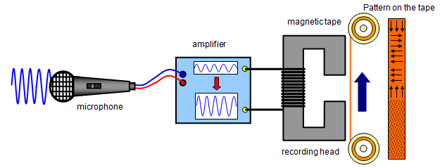
The faster the tape moves the better the recording because the information (lets say the music) is spread out over a longer piece of tape. Slow tape speed compresses the information into a small length and a poorer recording results. The recording head should be as close to the tape as possible so that the changing magnetic field can affect the iron oxide grains more easily.
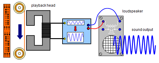
The reverse happens at the playback stage. A changing magnetic field on the tape is converted to a voltage by the playback head, this is amplified by the amplifier and then fed to a loudspeaker.
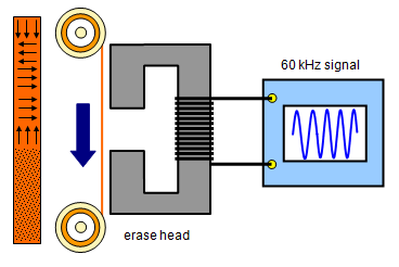
The tape recorder also has an erase head. This is fed by a high frequency signal (60 kHz) which is well about the range of human hearing. This signal jumbles up the tiny iron oxide grains before a new recording takes place. This is done to make sure that none of the previous recording is left on the tape.
The signals may be recorded as either digital or analogue. Magnetic recording techniques are used in the hard disc drives in computers and the floppy discs but not in CDs where a laser is used.
Preservation of magnetic audiotape comprises techniques for handling, cleaning and storage of magnetic audiotapes in an archival repository. Multiple types of magnetic media exist but are mainly in the form of open reels or enclosed cassettes. Although digitization of materials on fragile magnetic media in library and information science is a common practice, there remains a need for conserving the actual physical magnetic tape and playback equipment as artifacts.


Magnetic tape is a medium for magnetic recording, made of a thin, magnetizable coating on a long, narrow strip of plastic film. It was developed in Germany, based on magnetic wire recording. Devices that record and play back audio and video using magnetic tape are tape recorders and video tape recorders. A device that stores computer data on magnetic tape is a tape drive (tape unit, streamer).
Magnetic tape revolutionized broadcast and recording. When all radio was live, it allowed programming to be recorded. At a time when gramophone records were recorded in one take, it allowed recordings to be made in multiple parts, which were then mixed and edited with tolerable loss in quality. It was a key technology in early computer development, allowing unparalleled amounts of data to be mechanically created, stored for long periods, and to be rapidly accessed.
Nowadays, other technologies can perform the functions of magnetic tape. In many cases, these technologies are replacing tape. Despite this, innovation in the technology continues, and Sony and IBM continue to produce new magnetic tape drives.[1]
Over years, magnetic tape made in the 1970s and 1980s can suffer from a type of deterioration called sticky-shed syndrome. Caused by hydrolysis of the binder of the tape, it can render the tape unusable
Construction
The oxide side of a tape is the surface that can be magnetically manipulated by a tape head. This is the side that stores the information, the opposite side is simply a substrate to hold the tape together. The name originates from the fact that the magnetic side of most tapes is made of an oxide of iron. Sometimes chromium is also used.Audio recording
Magnetic tape was invented for recording sound by Fritz Pfleumer in 1928 in Germany, based on the invention of magnetic wire recording by Oberlin Smith in 1888 and Valdemar Poulsen in 1898. Pfleumer's invention used a ferric oxide (Fe
2O
3) powder coating on a long strip of paper. This invention was further developed by the German electronics company AEG, which manufactured the recording machines and BASF, which manufactured the tape. In 1933, working for AEG, Eduard Schuller developed the ring-shaped tape head. Previous head designs were needle-shaped and tended to shred the tape. An important discovery made in this period was the technique of AC biasing, which improved the fidelity of the recorded audio signal by increasing the effective linearity of the recording medium.
Due to the escalating political tensions, and the outbreak of World War II, these developments were largely kept secret. Although the Allies knew from their monitoring of Nazi radio broadcasts that the Germans had some new form of recording technology, the nature was not discovered until the Allies acquired captured German recording equipment as they invaded Europe in the closing of the war. It was only after the war that Americans, particularly Jack Mullin, John Herbert Orr, and Richard H. Ranger, were able to bring this technology out of Germany and develop it into commercially viable formats.
A wide variety of recorders and formats have developed since, most significantly reel-to-reel and Compact Cassette.
Video recording
The practice of recording and editing audio using magnetic tape rapidly established itself as an obvious improvement over previous methods. Many saw the potential of making the same improvements in recording television. Television ("video") signals are similar to audio signals. A major difference is that video signals use more bandwidth than audio signals. Existing audio tape recorders could not practically capture a video signal. Many set to work on resolving this problem. Jack Mullin (working for Bing Crosby) and the BBC both created crude working systems that involved moving the tape across a fixed tape head at very fast speeds. Neither system saw much use. It was the team at Ampex, led by Charles Ginsburg, that made the breakthrough of using a spinning recording head and normal tape speeds to achieve a very high head-to-tape speed that could record and reproduce the high bandwidth signals of video. The Ampex system was called Quadruplex and used 2-inch-wide (51 mm) tape, mounted on reels like audio tape, which wrote the signal in what is now called transverse scan.
A VHS helical scan head drum. Helical and transverse scans made possible to increase the data bandwidth to the necessary point for recording video on tapes, and not just audio.
Data storage
In all tape formats, a tape drive (or "transport" or "deck") uses motors to wind the tape from one reel to another, passing tape heads to read, write or erase as it moves.Magnetic tape was first used to record computer data in 1951 on the Eckert-Mauchly UNIVAC I. The recording medium was a thin strip of one half inch (12.65 mm) wide metal, consisting of nickel-plated bronze (called Vicalloy). Recording density was 128 characters per inch (198 micrometre/character) on eight tracks.

Small open reel of 9 track tape

Quarter inch cartridges, a data format commonly used in the 1980s and 1990s.
Tape remains a viable alternative to disk in some situations due to its lower cost per bit. This is a large advantage when dealing with large amounts of data. Though the areal density of tape is lower than for disk drives, the available surface area on a tape is far greater. The highest capacity tape media are generally on the same order as the largest available disk drives (about 5 TB in 2011). Tape has historically offered enough advantage in cost over disk storage to make it a viable product, particularly for backup, where media removability is necessary.
Tape has the benefit of a comparatively long duration during which the media can be guaranteed to retain the data stored on the media. Fifteen (15) to thirty (30) years of archival data storage is cited by manufacturers of modern data tape such as Linear Tape-Open media.
In 2002, Imation received a US$11.9 million grant from the U.S. National Institute of Standards and Technology for research into increasing the data capacity of magnetic tape.
In 2014 Sony and IBM announced that they had been able to record 148 gigabits per square inch with magnetic tape media developed using a new vacuum thin-film forming technology able to form extremely fine crystal particles, allowing true tape capacity of 185 TB.
Magnetic storage
Magnetic storage or magnetic recording is the storage of data on a magnetised medium. Magnetic storage uses different patterns of magnetisation in a magnetisable material to store data and is a form of non-volatile memory. The information is accessed using one or more read/write heads.
As of 2017[update], magnetic storage media, primarily hard disks, are widely used to store computer data as well as audio and video signals. In the field of computing, the term magnetic storage is preferred and in the field of audio and video production, the term magnetic recording is more commonly used. The distinction is less technical and more a matter of preference. Other examples of magnetic storage media include floppy disks, magnetic recording tape, and magnetic stripes on credit cards.

Longitudinal recording and perpendicular recording, two types of writing heads on a hard disk.
Magnetic storage in the form of wire recording—audio recording on a wire—was publicized by Oberlin Smith in the Sept 8, 1888 issue of the Electrical World. Smith had previously filed a patent in September, 1878 but found no opportunity to pursue the idea as his business was machine tools. The first publicly demonstrated (Paris Exposition of 1900) magnetic recorder was invented by Valdemar Poulsen in 1898. Poulsen's device recorded a signal on a wire wrapped around a drum. In 1928, Fritz Pfleumer developed the first magnetic tape recorder. Early magnetic storage devices were designed to record analog audio signals. Computers and now most audio and video magnetic storage devices record digital data.In old computers, magnetic storage was also used for primary storage in a form of magnetic drum, or core memory, core rope memory, thin film memory, twistor memory or bubble memory. Unlike modern computers, magnetic tape was also often used for secondary storage.
Design
Information is written to and read from the storage medium as it moves past devices called read-and-write heads that operate very close (often tens of nanometers) over the magnetic surface. The read-and-write head is used to detect and modify the magnetisation of the material immediately under it. There are two magnetic polarities, each of which is used to represent either 0 or 1.
The magnetic surface is conceptually divided into many small sub-micrometer-sized magnetic regions, referred to as magnetic domains, (although these are not magnetic domains in a rigorous physical sense), each of which has a mostly uniform magnetisation. Due to the polycrystalline nature of the magnetic material each of these magnetic regions is composed of a few hundred magnetic grains. Magnetic grains are typically 10 nm in size and each form a single true magnetic domain. Each magnetic region in total forms a magnetic dipole which generates a magnetic field. In older hard disk drive (HDD) designs the regions were oriented horizontally and parallel to the disk surface, but beginning about 2005, the orientation was changed to perpendicular to allow for closer magnetic domain spacing.
For reliable storage of data, the recording material needs to resist self-demagnetisation, which occurs when the magnetic domains repel each other. Magnetic domains written too densely together to a weakly magnetisable material will degrade over time due to rotation of the magnetic moment one or more domains to cancel out these forces. The domains rotate sideways to a halfway position that weakens the readability of the domain and relieves the magnetic stresses. Older hard disk drives used iron(III) oxide as the magnetic material, but current disks use a cobalt-based alloy.[1]
A write head magnetises a region by generating a strong local magnetic field, and a read head detects the magnetisation of the regions. Early HDDs used an electromagnet both to magnetise the region and to then read its magnetic field by using electromagnetic induction. Later versions of inductive heads included Metal In Gap (MIG) heads and thin film heads. As data density increased, read heads using magnetoresistance (MR) came into use; the electrical resistance of the head changed according to the strength of the magnetism from the platter. Later development made use of spintronics; in read heads, the magnetoresistive effect was much greater than in earlier types, and was dubbed "giant" magnetoresistance (GMR). In today's heads, the read and write elements are separate, but in close proximity, on the head portion of an actuator arm. The read element is typically magneto-resistive while the write element is typically thin-film inductive.
The heads are kept from contacting the platter surface by the air that is extremely close to the platter; that air moves at or near the platter speed. The record and playback head are mounted on a block called a slider, and the surface next to the platter is shaped to keep it just barely out of contact. This forms a type of air bearing.
Magnetic recording classes
Analog recording
Analog recording is based on the fact that remnant magnetisation of a given material depends on the magnitude of the applied field. The magnetic material is normally in the form of tape, with the tape in its blank form being initially demagnetised. When recording, the tape runs at a constant speed. The writing head magnetises the tape with current proportional to the signal. A magnetisation distribution is achieved along the magnetic tape. Finally, the distribution of the magnetisation can be read out, reproducing the original signal. The magnetic tape is typically made by embedding magnetic particles (approximately 0.5 micrometers [3] in size) in a plastic binder on polyester film tape. The most commonly-used of these was ferric oxide, though chromium dioxide, cobalt, and later pure metal particles were also used. Analog recording was the most popular method of audio and video recording. Since the late 1990s, however, tape recording has declined in popularity due to digital recording[4].Digital recording
Instead of creating a magnetisation distribution in analog recording, digital recording only needs two stable magnetic states, which are the +Ms and -Ms on the hysteresis loop. Examples of digital recording are floppy disks and hard disk drives (HDDs). Digital recording has also been carried out on tapes. However, HDDs offer superior capacities at reasonable prices; at the time of writing (2014), consumer-grade HDDs offer data storage at about 3 GB/$.Recording media on HDDs use a stack of thin films to store information and a read/write head to read and write information to and from the media; various developments have been carried out in the area of used materials.
Magneto-optical recording
Magneto-optical recording writes/reads optically. When writing, the magnetic medium is heated locally by a laser, which induces a rapid decrease of coercive field. Then, a small magnetic field can be used to switch the magnetisation. The reading process is based on magneto-optical Kerr effect. The magnetic medium are typically amorphous R-FeCo thin film (R being a rare earth element). Magneto-optical recording is not very popular. One famous example is Minidisc developed by Sony.Domain propagation memory
Domain propagation memory is also called bubble memory. The basic idea is to control domain wall motion in a magnetic medium that is free of microstructure. Bubble refers to a stable cylindrical domain. Data is then recorded by the presence/absence of a bubble domain. Domain propagation memory has high insensitivity to shock and vibration, so its application is usually in space and aeronautics.Technical details
Access method
Magnetic storage media can be classified as either sequential access memory or random access memory, although in some cases the distinction is not perfectly clear. The access time can be defined as the average time needed to gain access to stored records. In the case of magnetic wire, the read/write head only covers a very small part of the recording surface at any given time. Accessing different parts of the wire involves winding the wire forward or backward until the point of interest is found. The time to access this point depends on how far away it is from the starting point. The case of ferrite-core memory is the opposite. Every core location is immediately accessible at any given time.Hard disks and modern linear serpentine tape drives do not precisely fit into either category. Both have many parallel tracks across the width of the media and the read/write heads take time to switch between tracks and to scan within tracks. Different spots on the storage media take different amounts of time to access. For a hard disk this time is typically less than 10 ms, but tapes might take as much as 100 s.
Current usage
As of 2011[update], common uses of magnetic storage media are for computer data mass storage on hard disks and the recording of analog audio and video works on analog tape. Since much of audio and video production is moving to digital systems, the usage of hard disks is expected to increase at the expense of analog tape. Digital tape and tape libraries are popular for the high capacity data storage of archives and backups. Floppy disks see some marginal usage, particularly in dealing with older computer systems and software. Magnetic storage is also widely used in some specific applications, such as bank cheques (MICR) and credit/debit cards (mag stripes).Future
A new type of magnetic storage, called magnetoresistive random-access memory or MRAM, is being produced that stores data in magnetic bits based on the tunnel magnetoresistance (TMR) effect. Its advantage is non-volatility, low power usage, and good shock robustness. The 1st generation that was developed was produced by Everspin Technologies, and utilized field induced writing.[6] The 2nd generation is being developed through two approaches: thermal-assisted switching (TAS)[7] which is currently being developed by Crocus Technology, and spin-transfer torque (STT) on which Crocus, Hynix, IBM, and several other companies are working.[8] However, with storage density and capacity orders of magnitude smaller than an HDD, MRAM is useful in applications where moderate amounts of storage with a need for very frequent updates are required, which flash memory cannot support due to its limited write endurance. Six state MRAM is also being developed, echoing four bit multi level flash memory cells, that have six different bits, as opposed to two.Digital Audio Tape
Digital Audio Tape (DAT or R-DAT) is a signal recording and playback medium developed by Sony and introduced in 1987.[1] In appearance it is similar to a Compact Cassette, using 3.81 mm / 0.15" (commonly referred to as 4 mm) magnetic tape enclosed in a protective shell, but is roughly half the size at 73 mm × 54 mm × 10.5 mm. As the name suggests, the recording is digital rather than analog. DAT has the ability to record at higher, equal or lower sampling rates than a CD (48, 44.1 or 32 kHz sampling rate respectively) at 16 bits quantization. If a digital source is copied then the DAT will produce an exact clone, unlike other digital media such as Digital Compact Cassette or non-Hi-MD MiniDisc, both of which use a lossy data reduction system.
Like most formats of videocassette, a DAT cassette may only be recorded and played in one direction, unlike an analog compact audio cassette, although many DAT recorders had the capability to record program numbers and IDs, which can be used to select an individual track like on a CD player.
Although intended as a replacement for analog audio compact cassettes, the format was never widely adopted by consumers because of issues of expense and concerns from the music industry about unauthorized high-quality copies. The format saw moderate success in professional markets and as a computer storage medium, which was developed into the Digital Data Storage format. As Sony has ceased production of new recorders, it will become more difficult to play archived recordings in this format unless they are copied to other formats or hard drives.
Development
The technology of DAT is closely based on that of video recorders, using a rotating head and helical scan to record data. This prevents DATs from being physically edited in the cut-and-splice manner of analog tapes, or open-reel digital tapes like ProDigi or DASH.The DAT standard allows for four sampling modes: 32 kHz at 12 bits, and 32 kHz, 44.1 kHz or 48 kHz at 16 bits. Certain recorders operate outside the specification, allowing recording at 96 kHz and 24 bits (HHS). Some early machines aimed at the consumer market did not operate at 44.1 kHz when recording so they could not be used to 'clone' a compact disc. Since each recording standard uses the same tape, the quality of the sampling has a direct relation to the duration of the recording – 32 kHz at 12 bits will allow six hours of recording onto a three-hour tape while HHS will only give 90 minutes from the same tape. Included in the signal data are subcodes to indicate the start and end of tracks or to skip a section entirely; this allows for indexing and fast seeking. Two-channel stereo recording is supported under all sampling rates and bit depths, but the R-DAT standard does support 4-channel recording at 32 kHz.
DATs are between 15 and 180 minutes in length, a 120-minute tape being 60 metres in length. DATs longer than 60 metres tend to be problematic in DAT recorders due to the thinner media. DAT machines running at 48 kHz and 44.1 kHz sample rates transport the tape at 8.15 mm/s. DAT machines running at 32 kHz sample rate transport the tape at 4.075 mm/s.
Predecessor formats
DAT was not the first digital audio tape; pulse-code modulation (PCM) was used in Japan by Denon in 1972 for the mastering and production of analogue phonograph records, using a 2-inch Quadruplex-format videotape recorder for its transport, but this was not developed into a consumer product. Denon's development dated from its work with Japan's NHK Broadcasting; NHK developed the first high-fidelity PCM audio recorder in the late 1960s. Denon continued development of their PCM recorders that used professional video machines as the storage medium, eventually building 8-track units used for, among other productions, a series of jazz records made in New York in the late 1970s.In 1976, another digital audio tape format was developed by Soundstream, using one inch (25.4 mm) wide reel-to-reel tape loaded on an instrumentation recorder manufactured by Honeywell acting as a transport, which in turn was connected to outboard digital audio encoding and decoding hardware of Soundstream's own design. Soundstream's format was improved through several prototypes and when it was developed to 50 kHz sampling rate at 16 bits, it was deemed good enough for professional classical recording by the company's first client, Telarc Records of Cleveland, Ohio. Telarc's April, 1978 recording of the Holst Suites for Band by Fred Fennell and the Cleveland Wind Ensemble was a landmark release, and ushered in digital recording for America's classical music labels. Soundstream's system was also used by RCA.
Starting in 1978, 3M introduced its own line and format of digital audio tape recorders for use in a recording studio. One of the first prototypes of 3M's system was installed in the studios of Sound 80 in Minneapolis, Minnesota. This system was used in June 1978 to record Aaron Copland's "Appalachian Spring" by the St. Paul Chamber Orchestra conducted by Dennis Russell Davies. That record was the first Grammy-winning digital recording. The production version of the 3M Digital Mastering System was used in 1979 to record the first all-digital rock album, Ry Cooder's "Bop Till You Drop," made at Warner Brothers Studio in California.
The first consumer-oriented PCM format used consumer video tape formats (Beta and VHS) as the storage medium. These systems used the EIAJ digital format, which sampled at 44.056 kHz at 14 bits. The Sony PCM-F1 system debuted in 1981, and Sony from the start offered the option of 16-bit wordlength. Other systems were marketed by Akai, JVC, Nakamichi and others. Panasonic, via its Technics division, briefly sold a digital recorder that combined an EIAJ digital adapter with a VHS video transport, the SV-P100. These machines were marketed by consumer electronics companies to consumers, but they were very pricey compared to cassette or even reel-to-reel decks of the time. They did catch on with the more budget conscious professional recordists, and some boutique-label professional releases were recorded using these machines.[2]
Starting in the early 1980s, professional systems using a PCM adaptor were also common as mastering formats. These systems digitized an analog audio signal and then encoded the resulting digital stream into an analog video signal so that a conventional VCR could be used as a storage medium.
One of the most significant examples of a PCM adaptor-based system was the Sony PCM-1600 digital audio mastering system, introduced in 1978. The PCM-1600 used a U-Matic-format VCR for its transport, connected to external digital audio processing hardware. It (and its later versions such as the PCM-1610 and 1630) was widely used for the production and mastering of some of the first Digital Audio CDs in the early 1980s. Once CDs were commercially introduced in 1982, tapes recorded on the PCM-1600 were sent to the CD pressing plants to be used to make the glass master disc for CD replication.
Other examples include dbx, Inc.'s Model 700 system, which, similar to modern Super Audio CDs, used a high sample-rate delta-sigma modulation rather than PCM; Decca's 1970s PCM system,[3] which used a videotape recorder manufactured by IVC for a transport; and Mitsubishi's X-80 digital recorder, a 6.4 mm (¼ in) open reel digital mastering format that used a very unusual sampling rate of 50.4 kHz.
For high-quality studio recording, all of these formats were effectively made obsolete in the early 1980s by two competing reel-to-reel formats with stationary heads: Sony's DASH format and Mitsubishi's continuation of the X-80 recorder, which was improved upon to become the ProDigi format. (In fact, one of the first ProDigi-format recorders, the Mitsubishi X-86C, was playback-compatible with tapes recorded on an X-80.) Both of these formats remained popular as an analog alternative until the early 1990s, when hard disk recorders rendered them obsolete.
R-DAT and DCC
The DAT recorder mechanism was considerably more complex and expensive than an analogue cassette deck mechanism due to the rotary helical scan head, therefore Philips and Panasonic Corporation developed a rival digital tape recorder system with a stationary head based on the analogue compact cassette. The DCC was cheaper and simpler mechanically than DAT, but did not make perfect digital copies as it used a lossy compression technique called PASC. (Lossy compression was necessary to reduce the data rate to a level that the DCC head could record successfully at the linear tape speed of 4.75 cm/s that the compact cassette system uses.) DCC was never a competitor to DAT in recording studios, because DAT was already established, and as it was launched at the same time as Sony's Minidisc format (which has random access and editing features), it was not successful with consumers either. However, DCC proved that high quality digital recording could be achieved with a cheap simple mechanism using stationary heads.Anti-DAT lobbying
In the late 1980s, the Recording Industry Association of America (RIAA) unsuccessfully lobbied against the introduction of DAT devices into the U.S. Initially, the organization threatened legal action against any manufacturer attempting to sell DAT machines in the country. It later sought to impose restrictions on DAT recorders to prevent them from being used to copy LPs, CDs, and prerecorded cassettes. One of these efforts, the Digital Audio Recorder Copycode Act of 1987 (introduced by Sen. Al Gore and Rep. Waxman), instigated by CBS Records president Walter Yetnikoff, involved a technology called CopyCode and required DAT machines to include a chip to detect attempts to copy material recorded with a notch filter,[4] meaning that copyrighted prerecorded music, whether analog or digital, whether on LP, cassette, or DAT, would have distorted sound resulting from the notch filter applied by the publisher at the time of mastering for mass reproduction. A National Bureau of Standards study showed that not only were the effects plainly audible, but that it was not even effective at preventing copying.
This opposition by CBS softened after Sony, a DAT manufacturer, bought CBS Records in January 1988. By June 1989, an agreement was reached, and the only concession the RIAA would receive was a more practical recommendation from manufacturers to Congress that legislation be enacted to require that recorders have a Serial Copy Management System to prevent digital copying for more than a single generation.[5] This requirement was enacted as part of the Audio Home Recording Act of 1992, which also imposed taxes on DAT recorders and blank media. However, the computer industry successfully lobbied to have personal computers exempted from that act, setting the stage for massive consumer copying of copyrighted material on materials like recordable CDs and by extension, filesharing systems such as Napster.
Uses of DAT
Professional recording industry
DAT was used professionally in the 1990s by the professional audio recording industry as part of an emerging all-digital production chain also including digital multi-track recorders and digital mixing consoles that was used to create a fully digital recording. In this configuration, it is possible for the audio to remain digital from the first AD converter after the mic preamp until it is in a CD player.Pre-recorded DAT
In December 1987, The Guitar And Other Machines by the British post-punk band The Durutti Column, became the first commercial release on DAT. Later in May 1988, Wire released their album The Ideal Copy on the format.[7] Several other albums from multiple record labels were also released as pre-recorded DATs in the first few years of the format's existence, in small quantities as well. Factory Records released a small number of albums on the format, including New Order's best-selling compilation Substance 1987, but many planned releases were cancelled.[8]Amateur and home use
DAT was envisaged by proponents as the successor format to analogue audio cassettes in the way that the compact disc was the successor to vinyl-based recordings. It sold well in Japan, where high-end consumer audio stores stocked DAT recorders and tapes into the 2010s and second-hand stores generally continued to offer a wide selection of mint condition machines. However, there and in other nations, the technology was never as commercially popular as CD or cassette. DAT recorders proved to be comparatively expensive and few commercial recordings were available. Globally, DAT remained popular, for a time, for making and trading recordings of live music since available DAT recorders predated affordable CD recorders.
Computer data storage media
The format was designed for audio use, but through the ISO Digital Data Storage standard was adopted for general data storage, storing from 1.3 to 80 GB on a 60 to 180 meter tape depending on the standard and compression. It is a sequential-access medium and is commonly used for backups. Due to the higher requirements for capacity and integrity in data backups, a computer-grade DAT was introduced, called DDS (Digital Data Storage). Although functionally similar to audio DATs, only a few DDS and DAT drives (in particular, those manufactured by Archive for SGI workstations)[9] are capable of reading the audio data from a DAT cassette. SGI DDS4 drives no longer have audio support; SGI removed the feature due to "lack of demand".[10]Future of DAT
In November 2005, Sony announced that its remaining DAT machine models would be discontinued the following month.[11] Sony has sold around 660,000 DAT products since its introduction in 1987.[ However, the DAT format still finds regular use in film and television recording,primarily due to the support in some recorders for SMPTE time code synchronisation, and sometimes by audio enthusiasts as a way of backing up vinyl, compact cassette and CD collections to a digital format to then be transferred to PC. Although it is being superseded by modern hard disk recording or memory card equipment, which offers much more flexibility and storage, Digital Data Storage tapes, which are broadly similar to DATs, apart from tape length and thickness on some variants, and are still manufactured today unlike DAT cassettes, are often used as substitutes in many situations.In 2004, Sony introduced the Hi-MD Walkman with the ability to record in linear PCM. Although the Hi-MD format did find some favour as a disc-based DAT alternative for field recordings and general portable playback, Hi-MD manufacture ended in 2012.
Digital Compact Cassette
The Digital Compact Cassette (DCC) is a magnetic tape sound recording format introduced by Philips and Matsushita in late 1992 and marketed as the successor to the standard analog Compact Cassette. It was also a direct competitor to Sony's MiniDisc (MD), but neither format toppled the then-ubiquitous analog cassette despite their technical superiority. Another competing format, the Digital Audio Tape (DAT) had by 1992 also failed to sell in large quantities (although it was established in recording studios)—DCC was envisaged as a less expensive alternative to DAT. DCC shares a similar form factor to analog compact cassettes, and DCC recorders can play back either type of cassette. This backward compatibility allowed users to adopt digital recording without rendering their existing tape collections completely obsolete.

DCC signalled the parting of ways of Philips and Sony, who had worked together successfully on the standard Compact Disc, CD-ROM, and CD-i before. Based on the success of Digital Audio Tape in professional environments, both companies saw a market for a new consumer-oriented digital audio recording system that would be less expensive and perhaps less fragile. Sony decided to create the entirely new MiniDisc format (based on their experience with magneto-optical recording and Compact Disc) while Philips decided on a tape format that was compatible with their earlier analog Compact Cassette format.
DCC, initially referred to as S-DAT (stationary-head digital audio tape, as opposed to R-DAT—rotary-head digital audio tape),[1] was developed in cooperation with Matsushita, and the first DCC recorders, were introduced at the CES in Chicago in May, 1992[2] and the Firato consumer electronics show in Amsterdam in September 1992. At that time, not only Philips and Technics (brand of Matsushita) announced DCC recorders but also other brands such as Grundig and Marantz (both related to Philips at the time).
More recorders and players were introduced by Philips and other manufacturers in the following years, including some portable players and recorders as well as in-dash DCC/radio combinations for automotive use.[citation needed]
At the HCC-dagen computer fair in Utrecht, Netherlands, on November 24, 25, and 26, 1995, Philips presented the DCC-175 portable recorder that can be connected to an IBM-compatible PC using the "PC-link" cable. This was the only DCC recorder that can be connected to and controlled by a computer, and it was only ever available in the Netherlands.[citation needed]
Philips marketed the DCC format in Europe, the United States, and Japan. According to the newspaper article that announced the demise of DCC, DCC was more popular than MiniDisc in Europe (especially in the Netherlands).[3]
DCC was quietly discontinued in October 1996[3] after Philips admitted it had failed at achieving any significant market penetration with the format, and unofficially conceded victory to Sony. However, the MiniDisc format had not done very well either; the price of both systems had been too high for the younger market, and audiophiles rejected MD and DCC because in their opinion, the lossy compression deteriorated the audio quality too much.[4]
Technology

Magneto-Resistive stationary heads
DCC uses a 9-track magneto-resistive (MR) head for playback. The head is fixed to the mechanism of the recorder, unlike rotary heads that are used in helical scan systems such as DAT or VHS to increase head-to-tape speed. Because of the reduced number of moving parts, DCC decks are less sensitive to shock and vibration. And because of the dimensions that are so similar to analog compact cassettes, existing auto-reverse audio cassette recorder mechanisms can easily be adapted for use in DCC recorders simply by mounting a DCC head instead of only an analog head. In fact, Philips did this during development.[5]Magneto-resistive heads do not use iron so they do not build up residual magnetism. They never need to be demagnetized, and if a cassette demagnetizer is used on MR heads, they are easily damaged or destroyed.
Various head assemblies were used, according to the service manuals:
- Stationary DCC recorders (i.e. recorders meant for use in home stereo systems) such as the DCC-900 use a head assembly that has 9 (MR) playback heads and 9 (coil) recording heads for DCC, and two (MR) heads for playing analog compact cassettes. This type of head assembly was designed to be rotated by the mechanism when the recorder/player switched from side A to side B.
- Playback-only portable players such as the DCC-130 and DCC-134 used head assemblies with 18 MR heads, nine for each side of the cassette. When playing analog cassettes, two of the MR heads are used. The head assembly is fixed to the mechanism and does not need to rotate for side B.
- Portable recorders such as the DCC-170 and DCC-175 use head assemblies with 18 MR heads for DCC playback, 18 coil heads for DCC recording, and 4 MR heads for analog playback (a total of 40 heads in one head assembly). This head assembly is fixed to the mechanism and does not need to rotate for side B.
Tape specifications and PASC audio compression
The tape speed of DCC is the same as for analog compact cassettes: 1 7⁄8 inches (4.8 cm) per second, DCCs use tape that is the same width as that from analog compact cassettes: 1/8 of an inch (3.175 mm). The tape that is used in production cassettes is chromium dioxide- or cobalt-doped ferric-oxide, 3-4 µm thick in a total tape thickness of 12 µm,[6] identical to the tape that was widely in use for video tapes.Nine heads are used to read/write half the width of the tape; the other half of the width are used for the B-side. Eight of these tracks contain audio data, the ninth track is used for auxiliary information such as song titles and track markers, as well as markers to make the player switch from side A to side B (with or without winding towards the end of the tape first) and end-of-tape markers.
The (theoretical) maximum capacity of a DCC tape is 120 minutes, compared to 3 hours for DAT; however, no 120-minute tapes were ever produced. Also, because of the time needed for the mechanism to switch direction, there is always a short interruption in the audio between the two sides of the tape. DCC recorders can record from digital sources that use the S/PDIF standard, at sample rates of 32 kHz, 44.1 kHz or 48 kHz, or they can record from analog sources at 44.1 kHz.[citation needed]
Because of the low tape speed, the achievable bit rate of DCC is limited. To compensate, DCC uses an audio compression codec based on MPEG-1 audio layer I (MP1) and termed PASC (precision adaptive sub-band coding). MPEG and PASC use digital filters to convert the audio into 32 frequency subbands, and then use adaptive allocation and scaling to decide how many bits should be assigned to represent each frequency band. When decoding, the subband bit stream is used to synthesize an uncompressed bit stream again. PASC lowers the typical bitrate of a CD recording of approximately 1.4 megabits per second to 384 kilobits per second, a compression ratio of around 4:1. The difference in quality between PASC and the 5:1 compression used by early versions of ATRAC in the original MiniDisc is largely a subjective matter
After adding system information (such as emphasis settings, SCMS information, time code) and adding Reed-Solomon error correction bits to the 384 kbit/s data stream, followed by 8b/10b encoding,[7] the resulting bit rate is 768 kbit/s, which is recorded onto the eight data tracks at 96 kbit/s per track in a checkered pattern.[8] According to the Philips webpage,[6] it is possible for a DCC recorder to recover all missing data from a tape even if one of the 8 audio tracks is completely unreadable, or if all tracks are unreadable for 1.45 mm (about 0.03 seconds).
Auxiliary track
On prerecorded tapes, the information about album artist, album title, and track titles and lengths is recorded in the auxiliary ninth track continuously for the length of the entire tape. This makes it possible for players to recognize immediately what the tape position is and how to get to any of the other tracks (including which side of the tape to turn to), as soon as a tape is inserted and playback is started, regardless of whether the tape was rewound before inserting or not.On user tapes, a track marker is recorded at the beginning of every track, so that it is possible to skip and repeat tracks automatically. The markers are be automatically recorded when a silence is detected during an analog recording, or when a track marker is received in the S/PDIF signal of a digital input source (this track marker is automatically be generated by CD players). It is possible to remove these markers (to "merge tracks"), or add extra markers (to "split tracks") without rerecording the audio. Furthermore, it is possible to add markers afterwards that will signal the end of the tape or the end of the tape side, so that during playback, the player will stop the mechanism or fast-forward to the end of the A-side or will switch from A-side to B-side immediately.
On later generations of recorders, it is possible to make a third tape type, referred to by service documentation as "super-user tapes". The DCC-730 and DCC-951 make it possible to enter title information for each track, which is recorded on the auxiliary track after the start-of-track marker. Because the title information is only stored in one place, so unlike prerecorded tapes where users can see the names of all tracks on a tape, it is not possible to see tracks names of any other track than the one that is currently playing.
The three tape types (prerecorded, standard-user, and super-user) are compatible with all recorders and it is impossible (and unnecessary) to recognize the difference between a standard-user tape and a super-user tape without playing it. There are some interesting minor compatibility problems with text on super-user tapes; for example:
- On stationary recorders that have simple fourteen-segment displays, all track information is converted to upper case. They are capable of displaying symbols that are impossible to enter with their own track information editors (such as the apostrophe), but they are unable to show lower-case characters.
- The Philips DCC-822/DCC-824 car stereo with DCC player has a full dot-matrix text display which can display upper-case and lower-case titles from prerecorded tapes as well as super-user tapes.
- Later-generation portable recorders DCC-170 and DCC-175 are capable of displaying text information from prerecorded tapes, but not from super-user tapes. The DCC-175 is capable of writing and reading the text information to/from a super-user tape via the PC, but does not show the text information on the display.
Copy protection
All DCC recorders use the SCMS copy-protection system, which uses two bits in the S/PDIF digital audio stream and on tape to differentiate between protected vs. unprotected audio, and between original vs. copy:- Recording digitally from a source marked "protected" and "original" (produced by an audio CD or a prerecorded DCC, for example) was allowed, but the recorder will change the "original" bit to the "copy" state on the new tape to prevent copying of the copy.
- Recording digitally from a source marked "unprotected" is also allowed; the "original/copy" marker is ignored.
- Recording digitally from a source marked "protected" and "copy" is not allowed: the record button will not work and any ongoing recordings will stop, and an error message is shown on the display.
Cassettes and cases
DCCs are similar to compact cassettes, except that there are no "bulges" where the tape-access holes are located. The top side of a DCC is flat and there are no access holes for the hubs on there (they are not required because auto-reverse is a standard feature on all DCC decks), so this side can be used for a bigger label than can be used on an analog compact cassette. A spring-loaded metal shutter similar to the shutters on 3.5 inch floppy disks and MiniDiscs covers the tape access holes and locks the hubs while the cassette is not in use. Cassettes provide several extra holes and indentations so that DCC recorders can tell a DCC apart from an analog compact cassette, and so they can tell what the length of a DCC tape is. Also, there is a sliding marker on the DCC to enable and disable recording. Unlike the break-away notches on analog compact cassettes and VHS tapes, this marker makes it easier to make a tape recordable again, and unlike on analog compact cassettes, the marker protects the entire tape rather than just one side.The cases that DCCs come in generally do not have the characteristic folding mechanism of those for analog compact cassettes. Instead, DCC cases tend to be simply plastic boxes that are open on one of the short sides. The front side has a hole that is almost the size of the cassette, so that any label on the cassette is exposed even when the cassette is in its case. This allows the user to slide the cassette into and out of the case with one hand, and it reduced production costs, especially for prerecorded cassettes, because a label is needed only for the cassette rather than for the case. Format partner Matsushita does, however, produce blank cassettes (under their Panasonic brand) with a clam-shell-style case. Because DCCs have no "bulges" near the tape access holes, there is more space in the case behind the cassette to insert, for example, a booklet for a prerecorded tape, or a folded up card on which users could write the contents of the tape. In spite of the differences, the outside measurements of the standard DCC cases are exactly identical to the cases of analog compact cassettes, so they can be used in existing storage systems. The Matsushita-designed clam-shell case is slightly thinner than an analog compact cassette case is.
Data recording
There is only one DCC recorder that has the capability of being connected to and controlled by a computer: the DCC-175. It is a portable recorder that was developed by Marantz in Japan (unlike most of the other Philips recorders which were developed in the Netherlands and Belgium), and looks very similar to the other portables available from Philips and Marantz at the time: the DCC-134 and the DCC-170. The DCC-175 was sold only in the Netherlands, and was available separately or in a package with the "PC-link" data cable which can be used to connect the recorder to a parallel port of an IBM-compatible PC. Only small quantities of both recorder and cable were made, leaving many people searching for one or both at the time of the demise of DCC.The DCC-175 Service Manual[9] shows that in the recorder, the cable was connected to the I²S bus that carries the PASC bitstream, and it is also connected to a dedicated serial port of the microcontroller, to allow the PC to control the mechanism and to read and write auxiliary information such as track markers and track titles. The parallel port connector of the cable contains a custom chip created especially for this purpose by Philips Key Modules, as well as a standard RAM chip. Philips made no detailed technical information available to the public about the custom chip and therefore it is impossible for people who own a DCC-175 but no PC-link cable to make their own version of the PC-link cable.
The PC-link cable package included software consisting of:
- DCC Backup for Windows, a backup program
- DCC Studio, a sound recorder and editor for Windows
- A DCC tape database program that works together with DCC Studio
The backup programs for DOS as well as Windows does not support long file names which had been introduced by Windows 95 just a few months before the release. Also, because the tape runs at its usual speed and data rate, it takes 90 minutes to record approximately 250 megabytes of uncompressed data. Other backup media common in those days are faster, have more capacity, and support long file names, so the DCC backup programs are relatively uninteresting for users.
The DCC Studio application, however, was a useful application that makes it possible to copy audio from tape to hard disk and vice versa, regardless of the SCMS status of the tape. This makes it possible to circumvent SCMS with DCC Studio. The program also allows users to manipulate the PASC audio files that were recorded to hard disk in various ways: they can change equalization settings, cut/copy and paste track fragments, and place and move audio markers and name those audio markers from the PC keyboard. It is possible to record a mix tape by selecting the desired tracks from a list, and moving the tracks around in a playlist. Then the user can click on the record button to copy the entire playlist back to DCC tape, while simultaneously recording markers (such as reverse and end-of-tape) and track titles. It is not necessary to record the track titles and tape markers separately (as you would do with a stationary recorder), and thanks to the use of a PC keyboard, it is possible to use characters in song titles that are not available when using a stationary machine's remote control.
The DCC Studio program uses the recorder as playback and recording device. Most PCs of that era do not have a sound card and none is needed either. Working with the PASC data directly without the need to compress and decompress, it also saves a lot of hard disk space, and most computers in that time would have had a hard time compressing and decompressing PASC data in real time anyway. However, many users complained that they would have liked to have the possibility of using uncompressed WAV audio files with the DCC Studio program, and Philips responded by mailing a floppy disk to registered users, containing programs to convert a WAV file to PASC and vice versa. Unfortunately this software is extremely slow (it takes several hours to compress a few minutes of PCM music in a WAV file to PASC) but it was soon discovered that the PASC files are simply MPEG-1 audio layer I files that use an under-documented padding feature of the MPEG standard to make all frames the same length, so then it became easy to use other MPEG decoding software to convert PASC to PCM and vice versa.
Derivatives
The technology of using stationary MR heads was later developed by OnStream for use as a data storage media for computers. MR heads are now also commonly used in hard disks, although hard disks now use the GMR variant, whereas DCCs use the earlier AMR.[10]A derivative technology developed originally for DCC is now being used for filtering beer. Silicon wafers with micrometer-scale holes are ideal for separating yeast particles from beer. The beer flows through the silicon wafer leaving the yeast particles behind, which results in a very clear beer. The manufacturing process for the filters was originally developed for the read/write heads of DCC decks
DVD
DVD (an abbreviation of "digital versatile disc"or "digital video disc")[7] is a digital optical disc storage format invented and developed by Panasonic, Philips, Sony, and Toshiba in 1995. The medium can store any kind of digital data and is widely used for software and other computer files as well as video programs watched using DVD players. DVDs offer higher storage capacity than compact discs while having the same dimensions.
Prerecorded DVDs are mass-produced using molding machines that physically stamp data onto the DVD. Such discs are a form of DVD-ROM because data can only be read and not written or erased. Blank recordable DVD discs (DVD-R and DVD+R) can be recorded once using a DVD recorder and then function as a DVD-ROM. Rewritable DVDs (DVD-RW, DVD+RW, and DVD-RAM) can be recorded and erased many times.
DVDs are used in DVD-Video consumer digital video format and in DVD-Audio consumer digital audio format as well as for authoring DVD discs written in a special AVCHD format to hold high definition material (often in conjunction with AVCHD format camcorders). DVDs containing other types of information may be referred to as DVD data discs .
Development

Comparison of several forms of disk storage showing tracks (tracks not to scale); green denotes start and red denotes end.
* Some CD-R(W) and DVD-R(W)/DVD+R(W) recorders operate in ZCLV, CAA or CAV modes, but most work in Constant linear velocity (CLV) mode.
* Some CD-R(W) and DVD-R(W)/DVD+R(W) recorders operate in ZCLV, CAA or CAV modes, but most work in Constant linear velocity (CLV) mode.
CD Video used analog video encoding on optical discs matching the established standard 120 mm (4.7 in) size of audio CDs. Video CD (VCD) became one of the first formats for distributing digitally encoded films in this format, in 1993.[11] In the same year, two new optical disc storage formats were being developed. One was the Multimedia Compact Disc (MMCD), backed by Philips and Sony, and the other was the Super Density (SD) disc, supported by Toshiba, Time Warner, Matsushita Electric, Hitachi, Mitsubishi Electric, Pioneer, Thomson, and JVC. By the time of the press launches for both formats in January 1995, the MMCD nomenclature had been dropped, and Philips and Sony were referring to their format as Digital Video Disc (DVD).[12][13]
Representatives from the SD camp asked IBM for advice on the file system to use for their disc, and sought support for their format for storing computer data. Alan E. Bell, a researcher from IBM's Almaden Research Center, got that request, and also learned of the MMCD development project. Wary of being caught in a repeat of the costly videotape format war between VHS and Betamax in the 1980s, he convened a group of computer industry experts, including representatives from Apple, Microsoft, Sun Microsystems, Dell, and many others. This group was referred to as the Technical Working Group, or TWG.
On August 14, 1995, an ad hoc group formed from five computer companies (IBM, Apple, Compaq, Hewlett-Packard, and Microsoft) issued a press release stating that they would only accept a single format.[14] The TWG voted to boycott both formats unless the two camps agreed on a single, converged standard. They recruited Lou Gerstner, president of IBM, to pressure the executives of the warring factions. In one significant compromise, the MMCD and SD groups agreed to adopt proposal SD 9, which specified that both layers of the dual-layered disc be read from the same side—instead of proposal SD 10, which would have created a two-sided disc that users would have to turn over.[15] As a result, the DVD specification provided a storage capacity of 4.7 GB for a single-layered, single-sided disc and 8.5 GB for a dual-layered, single-sided disc.[15] The DVD specification ended up similar to Toshiba and Matsushita's Super Density Disc, except for the dual-layer option (MMCD was single-sided and optionally dual-layer, whereas SD was two half-thickness, single-layer discs which were pressed separately and then glued together to form a double-sided disc[13]) and EFMPlus modulation designed by Kees Schouhamer Immink.
Philips and Sony decided that it was in their best interests to end the format war, and agreed to unify with companies backing the Super Density Disc to release a single format, with technologies from both. After other compromises between MMCD and SD, the computer companies through TWG won the day, and a single format was agreed upon. The TWG also collaborated with the Optical Storage Technology Association (OSTA) on the use of their implementation of the ISO-13346 file system (known as Universal Disk Format) for use on the new DVDs.
Adoption
Movie and home entertainment distributors adopted the DVD format to replace the ubiquitous VHS tape as the primary consumer digital video distribution format. They embraced DVD because it produces superior moving pictures and sound, provides superior data lifespan, and can be interactive. Interactivity on LaserDiscs had proven desirable to consumers, especially collectors. When LaserDisc prices dropped from approximately $100 per disc to $20 per disc at retail, this luxury feature became available for mass consumption. Simultaneously, the movie studios decided to change their home entertainment release model from a rental model to a for purchase model,[citation needed] and large numbers of DVDs were sold.At the same time, a demand for interactive design talent and services was created. Movies in the past had uniquely designed title sequences. Suddenly every movie being released required information architecture and interactive design components that matched the film's tone and were at the quality level that Hollywood demanded for its product.
DVD as a format had two qualities at the time that were not available in any other interactive medium: enough capacity and speed to provide high quality, full motion video and sound, and low cost delivery mechanism provided by consumer products retailers. Retailers would quickly move to sell their players for under $200, and eventually for under $50 at retail. In addition, the medium itself was small enough and light enough to mail using general first class postage. Almost overnight, this created a new business opportunity and model for business innovators to re-invent the home entertainment distribution model. It also gave companies an inexpensive way to provide business and product information on full motion video through direct mail.
Immediately following the formal adoption of a unified standard for DVD, two of the four leading video game console companies (Sega and The 3DO Company) said they already had plans to design a gaming console with DVDs as the source medium.[16] (Sony, despite being one of the developers of the DVD format and eventually the first company to actually release a DVD-based console, stated at the time that they had no plans to use DVD in their gaming systems.[16]) Game consoles such as the PlayStation 2, Xbox, and Xbox 360 use DVDs as their source medium for games and other software. Contemporary games for Windows were also distributed on DVD.
Specifications
The DVD specifications created and updated by the DVD Forum are published as so-called DVD Books (e.g. DVD-ROM Book, DVD-Audio Book, DVD-Video Book, DVD-R Book, DVD-RW Book, DVD-RAM Book, DVD-AR Book, DVD-VR Book, etc.).[1][2][3]Some specifications for mechanical, physical and optical characteristics of DVD optical discs can be downloaded as freely available standards from the ISO website.[17] There are also equivalent European Computer Manufacturers Association (Ecma) standards for some of these specifications, such as Ecma-267 for DVD-ROMs.[18] Also, the DVD+RW Alliance publishes competing recordable DVD specifications such as DVD+R, DVD+R DL, DVD+RW or DVD+RW DL. These DVD formats are also ISO standards.[19][20][21][22]
Some of DVD specifications (e.g. for DVD-Video) are not publicly available and can be obtained only from the DVD Format/Logo Licensing Corporation for a fee of US $5000.[23][24] Every subscriber must sign a non-disclosure agreement as certain information in the DVD Book is proprietary and confidential.[23]
DVD recordable and rewritable
DVD recordable
HP initially developed recordable DVD media from the need to store data for backup and transport.[25] DVD recordables are now also used for consumer audio and video recording. Three formats were developed: DVD-R/RW, DVD+R/RW (plus), and DVD-RAM. DVD-R is available in two formats, General (650 nm) and Authoring (635 nm), where Authoring discs may be recorded with CSS encrypted video content but General discs may not.[26]
Although most DVD writers can nowadays write the DVD+R/RW and DVD-R/RW formats (usually denoted by "DVD±RW" or the existence of both the DVD Forum logo and the DVD+RW Alliance logo), the "plus" and the "dash" formats use different writing specifications. Most DVD readers and players play both kinds of discs, though older models can have trouble with the "plus" variants.
Some first generation DVD players would cause damage to DVD±R/RW/DL when attempting to read them.
The form of the spiral groove that makes up the structure of a recordable DVD encodes unalterable identification data known as Media Identification Code (MID). The MID contains data such as the manufacturer and model, byte capacity, allowed data rates (also known as speed), etc
Dual-layer recording
Dual-layer recording (sometimes also known as double-layer recording) allows DVD-R and DVD+R discs to store significantly more data—up to 8.5 gigabytes per disc, compared with 4.7 gigabytes for single-layer discs.[27] Along with this, DVD-DLs have slower write speeds as compared to ordinary DVDs. When played, a slight transition can sometimes be seen in the playback when the player changes layers. DVD-R DL was developed for the DVD Forum by Pioneer Corporation; DVD+R DL was developed for the DVD+RW Alliance by Mitsubishi Kagaku Media (MKM) and Philips.[28]
A dual-layer disc differs from its single layered counterpart by employing a second physical layer within the disc itself. The drive with dual-layer capability accesses the second layer by shining the laser through the first semitransparent layer. In some DVD players, the layer change can exhibit a noticeable pause, up to several seconds.[29] This caused some viewers to worry that their dual-layer discs were damaged or defective, with the end result that studios began listing a standard message explaining the dual-layer pausing effect on all dual-layer disc packaging.
DVD recordable discs supporting this technology are backward-compatible with some existing DVD players and DVD-ROM drives.[28] Many current DVD recorders support dual-layer technology, and the price is now comparable to that of single-layer drives, although the blank media remain more expensive. The recording speeds reached by dual-layer media are still well below those of single-layer media.
Dual layer DVDs are recorded using Opposite Track Path (OTP).[30] DVD-ROM discs mastered for computer use are produced with track 0 starting at the inside diameter (as is the case with a single layer). Track 1 then starts at the outside diameter. DVD video discs are mastered slightly differently. The video is divided between the layers such that layer 1 can be made to start at the same diameter that layer 0 finishes. This speeds up the transition as the layer changes because although the laser does have to refocus on layer 1, it does not have to skip across the disc to find it.
Capacity
The basic types of DVD (12 cm diameter, single-sided or homogeneous double-sided) are referred to by a rough approximation of their capacity in gigabytes. In draft versions of the specification, DVD-5 indeed held five gigabytes, but some parameters were changed later on as explained above, so the capacity decreased. Other formats, those with 8 cm diameter and hybrid variants, acquired similar numeric names with even larger deviation.The 12 cm type is a standard DVD, and the 8 cm variety is known as a MiniDVD. These are the same sizes as a standard CD and a mini-CD, respectively. The capacity by surface (MiB/cm2) varies from 6.92 MiB/cm2 in the DVD-1 to 18.0 MiB/cm2 in the DVD-18.
As with hard disk drives, in the DVD realm, gigabyte and the symbol GB are usually used in the SI sense (i.e., 109, or 1,000,000,000 bytes).
Each DVD sector contains 2,418 bytes of data, 2,048 bytes of which are user data. There is a small difference in storage space between + and - (hyphen) formats:

| Designation | Sides | Layers (total) | Diameter (cm) | Capacity | ||
|---|---|---|---|---|---|---|
| (GiB) | ||||||
| DVD-1[33] | SS SL | 1 | 1 | 8 | 1.36 | |
| DVD-2 | SS DL | 1 | 2 | 8 | 2.47 | |
| DVD-3 | DS SL | 2 | 2 | 8 | 2.72 | |
| DVD-4 | DS DL | 2 | 4 | 8 | 4.95 | |
| DVD-5 | SS SL | 1 | 1 | 12 | 4.37 | |
| DVD-9 | SS DL | 1 | 2 | 12 | 7.95 | |
| DVD-10 | DS SL | 2 | 2 | 12 | 8.75 | |
| DVD-14[34] | DS SL+DL | 2 | 3 | 12 | 12.33 | |
| DVD-18 | DS DL | 2 | 4 | 12 | 15.90 | |


| Designation | Sides | Layers (total) | Diameter (cm) | Capacity | ||
|---|---|---|---|---|---|---|
| (GiB) | ||||||
| DVD-R | SS SL (1.0) | 1 | 1 | 12 | 3.68 | |
| DVD-R | SS SL (2.0) | 1 | 1 | 12 | 4.37 | |
| DVD-RW | SS SL | 1 | 1 | 12 | 4.37 | |
| DVD+R | SS SL | 1 | 1 | 12 | 4.37 | |
| DVD+RW | SS SL | 1 | 1 | 12 | 4.37 | |
| DVD-R | SS DL | 1 | 2 | 12 | 7.96 | |
| DVD-RW | SS DL | 1 | 2 | 12 | 7.96 | |
| DVD+R | SS DL | 1 | 2 | 12 | 7.96 | |
| DVD+RW | SS DL | 1 | 2 | 12 | 7.96 | |
| DVD-RAM | SS SL | 1 | 1 | 8 | 1.36* | |
| DVD-RAM | DS SL | 2 | 1 | 8 | 2.47* | |
| DVD-RAM | SS SL (1.0) | 1 | 1 | 12 | 2.40 | |
| DVD-RAM | SS SL (2.0) | 1 | 1 | 12 | 4.37 | |
| DVD-RAM | DS SL (1.0) | 2 | 1 | 12 | 4.80 | |
| DVD-RAM | DS SL (2.0) | 2 | 1 | 12 | 8.75* | |
| Type | Sectors | Bytes | KiB | MiB | GiB |
|---|---|---|---|---|---|
| DVD-R SL | 2,298,496 | 4,707,319,808 | 4,596,992 | 4,489.250 | 4.384 |
| DVD+R SL | 2,295,104 | 4,700,372,992 | 4,590,208 | 4,482.625 | 4.378 |
| DVD-R DL | 4,171,712 | 8,543,666,176 | 8,343,424 | 8,147.875 | 7.957 |
| DVD+R DL | 4,173,824 | 8,547,991,552 | 8,347,648 | 8,152.000 | 7.961 |
DVD drives and player
DVD drives are devices that can read DVD discs on a computer. DVD players are a particular type of devices that do not require a computer to work, and can read DVD-Video and DVD-Audio discs.Laser and optic
All three common optical disc media (Compact disc, DVD, and Blu-ray) use light from laser diodes, for its spectral purity and ability to be focused precisely. DVD uses light of 650 nm wavelength (red), as opposed to 780 nm (far-red, commonly called infrared) for CD. This shorter wavelength allows a smaller pit on the media surface compared to CDs (0.74 µm for DVD versus 1.6 µm for CD), accounting in part for DVD's increased storage capacity.
In comparison, Blu-ray Disc, the successor to the DVD format, uses a wavelength of 405 nm (violet), and one dual-layer disc has a 50 GB storage capacity.
Transfer rates
Read and write speeds for the first DVD drives and players were of 1,385 kB/s (1,353 KiB/s); this speed is usually called "1×". More recent models, at 18× or 20×, have 18 or 20 times that speed. Note that for CD drives, 1× means 153.6 kB/s (150 KiB/s), about one-ninth as swift.[33][35]
| Drive speed | Data rate | ~Write time (minutes)[36] | ||
|---|---|---|---|---|
| Mbit/s | MB/s | Single-Layer | Dual-Layer | |
| 1× | 11.08 | 1.39 | 57 | 103 |
| 2× | 22.16 | 2.77 | 28 | 51 |
| 2.4× | 26.59 | 3.32 | 24 | 43 |
| 2.6× | 28.81 | 3.60 | 22 | 40 |
| 4× | 44.32 | 5.54 | 14 | 26 |
| 6× | 66.48 | 8.31 | 9 | 17 |
| 8× | 88.64 | 11.08 | 7 | 13 |
| 10× | 110.80 | 13.85 | 6 | 10 |
| 12× | 132.96 | 16.62 | 5 | 9 |
| 16× | 177.28 | 22.16 | 4 | 6 |
| 18× | 199.44 | 24.93 | 3 | 6 |
| 20× | 221.60 | 27.70 | 3 | 5 |
| 22× | 243.76 | 30.47 | 3 | 5 |
| 24× | 265.92 | 33.24 | 2 | 4 |
DVD-Video
DVD-Video is a standard for distributing video/audio content on DVD media. The format went on sale in Japan in 1995, in the United States, Canada, Central America, and Indonesia in 1997, and in Europe, Asia, Australia, and Africa in 1998. DVD-Video became the dominant form of home video distribution in Japan when it first went on sale in 1995, but it shared the market for home video distribution in the United States until June 15, 2003, when weekly DVD-Video in the United States rentals began outnumbering weekly VHS cassette rentals.[37] DVD-Video is still the dominant form of home video distribution worldwide except for in Japan where it was surpassed by Blu-ray Disc when Blu-ray first went on sale in Japan on March 31, 2006.Security
The Content Scramble System (CSS) is a digital rights management (DRM) and encryption system employed on almost all commercially produced DVD-video discs. CSS utilizes a proprietary 40-bit stream cipher algorithm. The system was introduced around 1996 and was first compromised in 1999.The purpose of CSS is twofold:
- CSS prevents byte-for-byte copies of an MPEG (digital video) stream from being playable since such copies do not include the keys that are hidden on the lead-in area of the restricted DVD.
- CSS provides a reason for manufacturers to make their devices compliant with an industry-controlled standard, since CSS scrambled discs cannot in principle be played on noncompliant devices; anyone wishing to build compliant devices must obtain a license, which contains the requirement that the rest of the DRM system (region codes, Macrovision, and user operation prohibition) be implemented.[38]
Consumer restrictions
The rise of filesharing has prompted many copyright holders to display notices on DVD packaging or displayed on screen when the content is played that warn consumers of the illegality of certain uses of the DVD. It is commonplace to include a 90-second advertisement warning that most forms of copying the contents are illegal. Many DVDs prevent skipping past or fast-forwarding through this warning.Arrangements for renting and lending differ by geography. In the U.S., the right to re-sell, rent, or lend out bought DVDs is protected by the first-sale doctrine under the Copyright Act of 1976. In Europe, rental and lending rights are more limited, under a 1992 European Directive that gives copyright holders broader powers to restrict the commercial renting and public lending of DVD copies of their work.
DVD-Audio
DVD-Audio is a format for delivering high fidelity audio content on a DVD. It offers many channel configuration options (from mono to 5.1 surround sound) at various sampling frequencies (up to 24-bits/192 kHz versus CDDA's 16-bits/44.1 kHz). Compared with the CD format, the much higher-capacity DVD format enables the inclusion of considerably more music (with respect to total running time and quantity of songs) or far higher audio quality (reflected by higher sampling rates, greater sample resolution and additional channels for spatial sound reproduction).Despite DVD-Audio's superior technical specifications, there is debate[by whom?] as to whether the resulting audio enhancements are distinguishable in typical listening environments. DVD-Audio currently forms a niche market, probably due to the very sort of format war with rival standard SACD that DVD-Video avoided.
Security
DVD-Audio discs employ a DRM mechanism, called Content Protection for Prerecorded Media (CPPM), developed by the 4C group (IBM, Intel, Matsushita, and Toshiba).Although CPPM was supposed to be much harder to crack than a DVD-Video CSS, it too was eventually cracked, in 2007, with the release of the dvdcpxm tool. The subsequent release of the libdvdcpxm library (based on dvdcpxm) allowed for the development of open source DVD-Audio players and ripping software. As a result, making 1:1 copies of DVD-Audio discs is now possible with relative ease, much like DVD-Video discs.
Successor
However, unlike previous format changes, e.g., vinyl to Compact Disc or VHS videotape to DVD, there is no immediate indication that production of the standard DVD will gradually wind down, as they still dominate, with around 75% of video sales and approximately one billion DVD player sales worldwide as of 3 April 2011. In fact, experts claim that the DVD will remain the dominant medium for at least another five years as Blu-ray technology is still in its introductory phase, write and read speeds being poor and necessary hardware being expensive and not readily available.[41][42]
Consumers initially were also slow to adopt Blu-ray due to the cost.[43] By 2009, 85% of stores were selling Blu-ray Discs. A high-definition television and appropriate connection cables are also required to take advantage of Blu-ray disc. Some analysts suggest that the biggest obstacle to replacing DVD is due to its installed base; a large majority of consumers are satisfied with DVDs.[44] The DVD succeeded because it offered a compelling alternative to VHS. In addition, the uniform media size let manufacturers make Blu-ray players and now defunct format HD DVD players backward-compatible, so they can play older DVDs. This stands in contrast to the change from vinyl to CD, and from tape to DVD, which involved a complete change in physical medium. As of 2012[update] it is still commonplace for studios to issue major releases in "combo pack" format, including both a DVD and a Blu-ray disc (as well as, in many cases, a third disc with an authorized digital copy). Also, some multi-disc sets use Blu-ray for the main feature, but DVDs for supplementary features (examples of this include the Harry Potter "Ultimate Edition" collections, the 2009 re-release of the 1967 The Prisoner TV series, and a 2007 collection related to Blade Runner). Another reason cited (July 2011) for the slower transition to Blu-ray from DVD is the necessity of and confusion over "firmware updates" and needing an internet connection to perform updates.
This situation is similar to the changeover from 78 rpm shellac recordings to 45 rpm and 33⅓ rpm vinyl recordings. Because the new and old mediums were virtually the same (a disc on a turntable, played by a needle), phonograph player manufacturers continued to include the ability to play 78s for decades after the format was discontinued.
Manufacturers continue to release standard DVD titles as of 2017[update], and the format remains the preferred one for the release of older television programs and films. Some programs, such as Star Trek: The Original Series and Star Trek: The Next Generation must be re-scanned to produce a high definition version from the original film recordings. (Certain special effects were also updated to appear better in high-definition.)[45] In the case of Doctor Who, a series primarily produced on standard definition videotape between 1963 and 1989, BBC Video reportedly intended to continue issuing DVD-format releases of that series until at least November 2013.
DVDs are also facing competition from video on demand services. With increasing numbers of homes having high speed Internet connections, many people now have the option to either rent or buy video from an online service, and view it by streaming it directly from that service's servers, meaning that the customer need not have any form of permanent storage media for video at all. PWC predicts that online streaming revenue will overtake physical media sales revenue by 2018.[50]
Longevity
DVD longevity is measured by how long the data remains readable from the disc, assuming compatible devices exist that can read it: that is, how long the disc can be stored until data is lost. Numerous factors affect longevity: composition and quality of the media (recording and substrate layers), humidity and light storage conditions, the quality of the initial recording (which is sometimes a matter of mutual compatibility of media and recorder), etc.[51] According to NIST, "[a] temperature of 64.4°F (18°C) and 40% RH [Relative Humidity] would be considered suitable for long-term storage. A lower temperature and RH is recommended for extended-term storage."[52]According to the Optical Storage Technology Association (OSTA), "Manufacturers claim lifespans ranging from 30 to 100 years for DVD, DVD-R and DVD+R discs and up to 30 years for DVD-RW, DVD+RW and DVD-RAM."[53]
According to a NIST/LoC research project conducted in 2005-2007 using accelerated life testing, "There were fifteen DVD products tested, including five DVD-R, five DVD+R, two DVD-RW and three DVD+RW types. There were ninety samples tested for each product. [...] Overall, seven of the products tested had estimated life expectancies in ambient conditions of more than 45 years. Four products had estimated life expectancies of 30-45 years in ambient storage conditions. Two products had an estimated life expectancy of 15-30 years and two products had estimated life expectancies of less than 15 years when stored in ambient conditions." The life expectancies for 95% survival estimated in this project by type of product are tabulated
| Disc type | 0–15 years | 15–30 years | 30–45 years | over 45 years |
|---|---|---|---|---|
| DVD-R | 20% | 20% | 0% | 60% |
| DVD+R | 20% | 0% | 40% | 40% |
| DVD-RW | 0% | 0% | 50% | 50% |
| DVD+RW | 0% | 33.3% | 33.3% | 33.3% |
Block Diagrams
Tape Recorder Tutorial
The tape head consists of a ring of soft magnetic material, called the core, with a small gap in it.
A coil is wound around the core. The tape travels over the gap in the core.

As the audio signal varies in amplitude and frequency so does the magnetic field.
The tape consists of a plastic film coated with a material that is magnetised by the field as it passes over the gap.
As the magnetic field varies in strength so does the magnetism stored on the tape.
During playback the tape passes over the same head. (it is called the record/playback head).
This time the magnetism stored on the tape induces a voltage in the head coil.
This voltage is amplified and used to drive a loudspeaker.
Magnetic Disk
a digital computer memory in which the data carrier is a thin aluminum or plastic disk coated with a layer of magnetic material.
Magnetic disks are 180-1,200 mm in diameter and 2.5-5.0 mm thick; Ni-Co-P or Co-W alloys are used for the magnetic coating. Data are recorded magnetically on the disks in concentric tracks on the working surface and are coded by an address, which indicates the number of the disk and the number of the track. There may be a fixed magnetic head for recording or readout on each track or a single movable head that is common to several tracks and sometimes to several disks. The pickup lever of the selection mechanism, together with the magnetic heads mounted on it, is moved by an electric or pneumatic operating mechanism that moves the heads to any disk and also to any track on a disk. The most common design has “floating” heads.
A magnetic-disk memory usually contains several dozen disks mounted on a common axle, which is turned by an electric motor. One or more disks (a packet) may be replaced, creating disk index files. There may be as many as 100 disks in a memory and 64-5,000 data tracks on each operating surface of a disk; the recording density is 20-130 impulses per millimeter. The data capacity of magnetic disk memories ranges from several tens of thousands up to several billion bits, and the average access time is 10-100 millisec.
Magnetic disks appeared during the mid-1950’s and immediately became widely used because of their excellent technical characteristics. In speed of response they are between immediate-access memories and external storages. They can store an adequate volume of data, the cost per unit of stored information (bit) is low, and their service reliability is excellent
Tracks and Spots
The disk surface is divided into concentric tracks (circles within circles). The thinner the tracks, the more storage. The data bits are recorded as tiny magnetic spots on the tracks. The smaller the spot, the more bits per inch and the greater the storage.
Sectors
Tracks are further divided into sectors, which hold a block of data that is read or written at one time; for example, READ SECTOR 782, WRITE SECTOR 5448. In order to update the disk, one or more sectors are read into the computer, changed and written back to disk. The operating system figures out how to fit data into these fixed spaces.
Modern disks have more sectors in the outer tracks than the inner ones because the outer radius of the platter is greater than the inner radius (see CAV). See magnetic tape and optical disc.
The following magnetic disk technologies are summarized below. Several have been discontinued, but are often still used long after their official demise. Media tend to be made for many years thereafter.
Each grain of iron oxide acts like a tiny magnet and on a tape that has no data stored on it these gains are arranged irregularly on the tape – the tape is unmagnetised.
When you record data, lets say some music, on the tape the following things happen:
(a) the microphone picks up the sound wave and converts it to a small changing voltage
(b) the amplifier amplifies this voltage
(c) the output from the amplifier is fed to the recording head where a changing magnetic field is produced
(d) this changing magnetic field arranges the grains of iron oxide on the tape into a pattern that "mirrors" the changing sound received by the microphone.
The faster the tape moves the better the recording because the information (lets say the music) is spread out over a longer piece of tape. Slow tape speed compresses the information into a small length and a poorer recording results. The recording head should be as close to the tape as possible so that the changing magnetic field can affect the iron oxide grains more easily.
The reverse happens at the playback stage. A changing magnetic field on the tape is converted to a voltage by the playback head, this is amplified by the amplifier and then fed to a loudspeaker.
The tape recorder also has an erase head. This is fed by a high frequency signal (60 kHz) which is well about the range of human hearing. This signal jumbles up the tiny iron oxide grains before a new recording takes place. This is done to make sure that none of the previous recording is left on the tape.
The signals may be recorded as either digital or analogue. Magnetic recording techniques are used in the hard disc drives in computers and the floppy discs but not in CDs where a laser is used.
 As stated above, the human ear can hear frequencies from 20Hz to 20,000Hz (20kHZ). When a sound's frequency is on the lower end of our hearing scale (down near 20hz), we hear deep/low notes/sounds we commonly call Bass. When the frequency is up near 20kHz, we hear high-pitched sounds we commonly call Treble. We call the middle ground frequencies Midrange. Those of us who are fortunate enough to be able to hear most of these frequencies know that we are surrounded by sounds at all times; the world is a noisy place.
Humans are capable of creating sounds in many ways. Most of us can make sound with our vocal cords. Some of us are able to use our hands or lung power to make instruments produce sounds. Babies cry for their parents, children bang on plates, teenagers scream at their parents, and some of us use our knowledge of science to create eqiupment that can reproduce sound; speakers! We are all deeply connected to sound in many ways. Knowledge of how we create sound, and incororate it into our daily lives, will help you notice phenomena that you never knew were there.
 As you can see, there are not many parts. However, minimal variations in each component can have dramatic effect on the speaker's performance.
The Essentials: Cone, Suspension, Magnet, Voice Coil, and Frame.
The cone is the main moving mass of the speaker. The larger the cone, the more mass and surface area a speaker will have. The more surface area a speaker has, the more air it can move. The more air it can move, the louder the speaker can get; In a nutshell.
NOTE: Accurate, High frequency replication requires smaller specialty drivers; tweeters.
The suspension and the spider keep the voice coil aligned and act like a spring when the speaker is in motion. The suspension pulls the cone back to the center position when it moves back and forth. If there were no suspension, there would be nothing to hold the voice coil and cone in place. The rigidity, composition, and design of the suspension can greatly affect a speaker's performance. Below is a diagram of how a speaker's suspension works.
 The magnet structure is what creates the standing magnetic field. This standing magnetic field gives the voice coil's generated field something to push off of. A strong standing magnetic field allows greater cone motion potential. The stronger this field is, the further it spans thus allowing a voice coil's field more to push off of. The entire action is similar to the idea behind a solenoid. The below diagram demonstrates the voice coil's relationship with the standing magnet field.
 The voice coil and standing magnetic field are what makes the cone move. When an electrical current/signal from from an audio amplifier (alternating at the same frequency as the sound that created it) is put into a speaker's voice coil, the voice coil generates an alternating magnetic field. The alternating polarity of the voice coil causes it to be repelled-from and attracted-to the standing magnetic field. This action of alternating attracting and repelling causes the cone (attached to the voice coil) to move! When the cone moves between 20Hz-20 KHz, the speaker makes sound that we can hear!
All of the above components are held together by the frame. The voice coil is connected to the cone which is connected to the frame via the suspension and spider. The magnet structure is held in place by the frame. The frame keeps the family together and it has to be strong to keep everyone together when things start moving. Without anyone of these crucial components, the speaker would not exist.
 Drivers are specialist. Drivers are speakers that have a certain job to fill and that job is voicing a certain range of frequencies. There are traditionally three types of drivers: Woofers, Midrange, and tweeters. Woofers specialize in producing low frequencies and are the largest of the drivers. Midrange drivers specialize in producing midrange frequencies. Tweeters specialize in producing high frequencies.
Sub-woofers, which you may have heard of, are special drivers that focus on replicating very low frequencies; many of which we can't hear. This driver's purpose is to add the shake, rumble, and roll to a listening experience. Sub-woofers can bring a home theater system closer to sounding and feeling like a movie theater sound system which adds to your home theater experience. Sub-woofers can also make music listening feel like a live experience. Live music experiences are typically experienced at louder volumes where you can feel the bass and impact of the instruments. Subwoofers replicate this sensation but without the other frequencies being at high volume which can be uncomfortable to your ear.
 Although there are many different types, styles, and sizes, speakers just make sound. Knowing how they make sound can add a new dimension to a listening experience. Much like knowing a little bit about how a car works may change your driving habits, knowledge about speakers can help you operate them more efficiently. We hope this article helps you understand speakers a little more and gives you a little more confidence when you go out a purchase them.

Magnetic disks are 180-1,200 mm in diameter and 2.5-5.0 mm thick; Ni-Co-P or Co-W alloys are used for the magnetic coating. Data are recorded magnetically on the disks in concentric tracks on the working surface and are coded by an address, which indicates the number of the disk and the number of the track. There may be a fixed magnetic head for recording or readout on each track or a single movable head that is common to several tracks and sometimes to several disks. The pickup lever of the selection mechanism, together with the magnetic heads mounted on it, is moved by an electric or pneumatic operating mechanism that moves the heads to any disk and also to any track on a disk. The most common design has “floating” heads.
A magnetic-disk memory usually contains several dozen disks mounted on a common axle, which is turned by an electric motor. One or more disks (a packet) may be replaced, creating disk index files. There may be as many as 100 disks in a memory and 64-5,000 data tracks on each operating surface of a disk; the recording density is 20-130 impulses per millimeter. The data capacity of magnetic disk memories ranges from several tens of thousands up to several billion bits, and the average access time is 10-100 millisec.
Magnetic disks appeared during the mid-1950’s and immediately became widely used because of their excellent technical characteristics. In speed of response they are between immediate-access memories and external storages. They can store an adequate volume of data, the cost per unit of stored information (bit) is low, and their service reliability is excellent
magnetic disk
(storage)
A flat rotating disc covered on one or both sides with magnetisable material. The two main types are the hard disk and the floppy disk.
Data is stored on either or both surfaces of discs in concentric rings called "tracks". Each track is divided into a whole number of "sectors". Where multiple (rigid) discs are mounted on the same axle the set of tracks at the same radius on all their surfaces is known as a "cylinder".
Data is read and written by a disk drive which rotates the discs and positions the read/write heads over the desired track(s). The latter radial movement is known as "seeking". There is usually one head for each surface that stores data. To reduce rotational latency it is possible, though expensive, to have multiple heads at different angles.
The head writes binary data by magnetising small areas or "zones" of the disk in one of two opposing orientations. It reads data by detecting current pulses induced in a coil as zones with different magnetic alignment pass underneath it.
In theory, bits could be read back as a time sequence of pulse (one) or no pulse (zero). However, a run of zeros would give a prolonged absence of signal, making it hard to accurately divide the signal into individual bits due to the variability of motor speed. Run Length Limited is one common solution to this clock recovery problem.
High speed disks have an access time of 28 milliseconds or less, and low-speed disks, 65 milliseconds or more. The higher speed disks also transfer their data faster than the slower speed units.
The disks are usually aluminium with a magnetic coating. The heads "float" just above the disk's surface on a current of air, sometimes at lower than atmospheric pressure in an air-tight enclosure. The head has an aerodynamic shape so the current pushes it away from the disk. A small spring pushes the head towards the disk at the same time keeping the head at a constant distance from the disk (about two microns).
magnetic disk
The primary computer storage device. Like tape, it is magnetically recorded and can be re-recorded over and over. Disks are rotating platters with a mechanical arm that moves a read/write head between the outer and inner edges of the platter's surface. It can take as long as one second to find a location on a floppy disk to as little as a couple of milliseconds on a fast hard disk. See hard disk for more details.Tracks and Spots
The disk surface is divided into concentric tracks (circles within circles). The thinner the tracks, the more storage. The data bits are recorded as tiny magnetic spots on the tracks. The smaller the spot, the more bits per inch and the greater the storage.
Sectors
Tracks are further divided into sectors, which hold a block of data that is read or written at one time; for example, READ SECTOR 782, WRITE SECTOR 5448. In order to update the disk, one or more sectors are read into the computer, changed and written back to disk. The operating system figures out how to fit data into these fixed spaces.
Modern disks have more sectors in the outer tracks than the inner ones because the outer radius of the platter is greater than the inner radius (see CAV). See magnetic tape and optical disc.
 |
| Tracks and Sectors |
|---|
| Tracks are concentric circles on the disk, broken up into storage units called "sectors." The sector, which is typically 512 bytes, is the smallest unit that can be read or written. |
Magnetic Disk Summary
The following magnetic disk technologies are summarized below. Several have been discontinued, but are often still used long after their official demise. Media tend to be made for many years thereafter.
 |
| The Early 1990s |
|---|
| This RAID II prototype in 1992, which embodies principles of high performance and fault tolerance, was designed and built by University of Berkeley graduate students. Housing 36 320MB disk drives, its total storage was less than the disk drive in the cheapest PC only six years later. (Image courtesy of The Computer History Museum, www.computerhistory.org) See RAID. |
DISCONTINUED TECHNOLOGIES
 |
| The Early 1990s |
|---|
| This RAID II prototype in 1992, which embodies principles of high performance and fault tolerance, was designed and built by University of Berkeley graduate students. Housing 36 320MB disk drives, its total storage was less than the disk drive in the cheapest PC only six years later. (Image courtesy of The Computer History Museum, www.computerhistory.org) See RAID. |
Computer Desktop Encyclopedia copyright ©1981-2016 by The Computer Language Company Inc
Magnetic recording/audiocassette
Audiocassette tape recorders are widely used to record and play back music or speech. Information is stored on a narrow ribbon of plastic tape that has one side coated with a magnetic material consisting of magnetically active particles, most commonly iron oxide and chromium dioxide. As the tape passes around the five magnetic heads of a tape recorder, sound is recorded, replayed, or erased according to the heads that are activated.
A recording head (a small electromagnet) magnetizes the passing tape in such a way that the magnetic particles on it are realigned in a pattern that corresponds to the loudness and frequency (rate of vibration) of
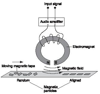
incoming sounds. The resulting pattern remains on the tape until erased or changed.
The tape of an audiocassette has a weak magnetic field (an area where a magnetic force is present) around it that varies from point to point depending on the pattern of its magnetic particles. The playback head contains a coil of wire. When the magnetized tape moves past the coil, an electrical current is created. The current will alternate in direction depending on the alignment of the magnetic particles as they pass by the playback head. The magnetic pattern originally recorded on the tape is transformed into a precisely corresponding electrical signal.
The electric current from the playback head is then amplified and sent to an audio speaker, which vibrates simultaneously with the varying current. The back-and-forth motion of the speaker creates pressure waves in the air. This causes the listener's eardrums to vibrate, producing the sensation of sound.
Electromagnet: A coil of wire surrounding an iron core that becomes magnetized when electric current flows through the wire.
Erase head: An electromagnet operating at an ultrasonic frequency (rate of vibration) to scramble previously recorded information on a tape.
Playback head: A small coil that senses the varying magnetic field of the moving tape and converts it into an electrical signal that can be amplified.
Recording head: An electromagnet that aligns the magnetic particles of the cassette tape while it moves by.
An audiocassette has a built-in erase head to remove previously recorded information. The tape has to be blank before it can be used again to make a new recording. The erase head normally is an electromagnet that operates at an ultrasonic frequency, much higher than the human ear can hear. It effectively scrambles the previously recorded magnetic particle patterns. Audiocassettes are designed so that the tape from the supply reel passes by the erase head just before the recording head.
The audiocassette was introduced in 1963 by the Philips Company of the Netherlands. The audiocassette made inserting, advancing, and rewinding a tape fast and easy. The tape could be stopped and ejected at any point. Because of this ease and economy, magnetic tape recordings could compete with long-playing records (LPs). The invention of the microchip allowed audiotape players to be made smaller and more portable. With the introduction of products such as Sony's compact Walkman™, cassettes became universally popular.
Although the audiocassette is economical and still widely used, digital technologies are revolutionizing the industry. Digital audio tape
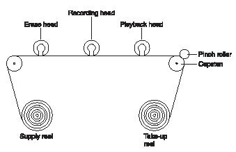
(DAT) recorders became widely available in the United States in 1990. A digital system enables a home recorder to make a tape copy that is an exact replica (not just an approximation) of the original sounds on a cassette that is half the size of a typical audiocassette. Digital technology records sound in a code of binary numbers (a series of zeroes and ones), so each subsequent recording is an exact copy of the code. These kinds of recordings do not suffer from the sound distortion that was the problem with the recordings they replaced.
A recording head (a small electromagnet) magnetizes the passing tape in such a way that the magnetic particles on it are realigned in a pattern that corresponds to the loudness and frequency (rate of vibration) of
Recording head. (Reproduced by permission of
The Gale Group
.) incoming sounds. The resulting pattern remains on the tape until erased or changed.
The tape of an audiocassette has a weak magnetic field (an area where a magnetic force is present) around it that varies from point to point depending on the pattern of its magnetic particles. The playback head contains a coil of wire. When the magnetized tape moves past the coil, an electrical current is created. The current will alternate in direction depending on the alignment of the magnetic particles as they pass by the playback head. The magnetic pattern originally recorded on the tape is transformed into a precisely corresponding electrical signal.
The electric current from the playback head is then amplified and sent to an audio speaker, which vibrates simultaneously with the varying current. The back-and-forth motion of the speaker creates pressure waves in the air. This causes the listener's eardrums to vibrate, producing the sensation of sound.
Words to Know
Digital audio tape (DAT): A technology developed in the 1990s, by which information is stored on magnetic tape in binary code.Electromagnet: A coil of wire surrounding an iron core that becomes magnetized when electric current flows through the wire.
Erase head: An electromagnet operating at an ultrasonic frequency (rate of vibration) to scramble previously recorded information on a tape.
Playback head: A small coil that senses the varying magnetic field of the moving tape and converts it into an electrical signal that can be amplified.
Recording head: An electromagnet that aligns the magnetic particles of the cassette tape while it moves by.
History of magnetic recording
The invention of magnetic recording tape is attributed to both American inventor J. A. O'Neill and German engineer Fritz Pfleumer (1881–1945). Pfleumer filed the first audiotape patent in 1929. In 1935, the German electronics firm AEG produced a prototype (first version) of a record/playback machine, called a magnetophon. It was based on Pfleumer's idea, but used a plastic tape. Another firm, BASF, went on to refine the tape AEG used, presenting the first usable magnetic tape in 1935.Types of magnetic recording machines
At one time, audiotape was used in a reel-to-reel format. This was a complicated and awkward procedure. Eight-track cartridges were another innovation in magnetic recording. These used an endless-loop format so the tape could be played continuously without being flipped over by the listener.The audiocassette was introduced in 1963 by the Philips Company of the Netherlands. The audiocassette made inserting, advancing, and rewinding a tape fast and easy. The tape could be stopped and ejected at any point. Because of this ease and economy, magnetic tape recordings could compete with long-playing records (LPs). The invention of the microchip allowed audiotape players to be made smaller and more portable. With the introduction of products such as Sony's compact Walkman™, cassettes became universally popular.
Although the audiocassette is economical and still widely used, digital technologies are revolutionizing the industry. Digital audio tape
Cassette and heads. (Reproduced by permission of
The Gale Group
.) (DAT) recorders became widely available in the United States in 1990. A digital system enables a home recorder to make a tape copy that is an exact replica (not just an approximation) of the original sounds on a cassette that is half the size of a typical audiocassette. Digital technology records sound in a code of binary numbers (a series of zeroes and ones), so each subsequent recording is an exact copy of the code. These kinds of recordings do not suffer from the sound distortion that was the problem with the recordings they replaced.
Tape recording
Although tape recorders have been replaced in everyday use by Cd players and devices such as iPods they still provide a really useful way to understand the ideas of electromagnetic induction. Tape recorders store the information music, speech or data, on plastic tape that is coated with iron oxide powder. You can tell that the tape is magnetic by attracting it with a magnet. Warning – don't try to do this with a tape that already has some music or data stored on it – you will ruin it!Each grain of iron oxide acts like a tiny magnet and on a tape that has no data stored on it these gains are arranged irregularly on the tape – the tape is unmagnetised.
When you record data, lets say some music, on the tape the following things happen:
(a) the microphone picks up the sound wave and converts it to a small changing voltage
(b) the amplifier amplifies this voltage
(c) the output from the amplifier is fed to the recording head where a changing magnetic field is produced
(d) this changing magnetic field arranges the grains of iron oxide on the tape into a pattern that "mirrors" the changing sound received by the microphone.
The faster the tape moves the better the recording because the information (lets say the music) is spread out over a longer piece of tape. Slow tape speed compresses the information into a small length and a poorer recording results. The recording head should be as close to the tape as possible so that the changing magnetic field can affect the iron oxide grains more easily.
The reverse happens at the playback stage. A changing magnetic field on the tape is converted to a voltage by the playback head, this is amplified by the amplifier and then fed to a loudspeaker.
The tape recorder also has an erase head. This is fed by a high frequency signal (60 kHz) which is well about the range of human hearing. This signal jumbles up the tiny iron oxide grains before a new recording takes place. This is done to make sure that none of the previous recording is left on the tape.
The signals may be recorded as either digital or analogue. Magnetic recording techniques are used in the hard disc drives in computers and the floppy discs but not in CDs where a laser is used.
Magnetic Recording

Magnetic Tapes
Magnetic Tapes

Magnetic Disks

Writing & Reading Data

Magnetic recording of the human voice was first carried out in 1898 by a Danish engineer, named Poulsen. The recording was made on a ferromagnetic wire, but due to a lack of amplification the recording quality was very poor. In 1927, magnetic tape was simultaneously invented in the USA and Germany. However, the familiar oxide tapes for audio recording were not developed until 1947, by the 3M corporation.
The first hard disk drive, known as the “RAMAC”, was introduced by IBM in 1957, and had a storage capacity of 2000 bits in-2. The storage capacity has rapidly and steadily increased since the “RAMAC” and in the year 2000 reached approximately 10 Gbits in-2, i.e. an increase by a factor of five million. This increase in storage capacity is illustrated in figure 1, in terms of the decrease in area on the disk required to store the information.
Figure 1: The block represents the size of one bit of data on a hard disk. The sizes have been enlarged 1000 times.
Magnetic Tapes
Magnetic Disks
Writing & Reading Data
Magnetic Tapes
Magnetic tapes are extensively used for recording audio and video signals, although it is unclear how long this technology will continue to be used with the rising popularity of the digital versatile disk (DVD).
Tapes can be made with either a particulate media adhered to a plastic substrate or a metal evaporated (ME) film on the substrate. The magnetic layer on a particulate tape is only 40% magnetic material whereas ME tapes have a 100% magnetic layer. Therefore, ME tapes give better quality recording, but they are more time consuming to produce and are more expensive. Particulate tapes are much cheaper and hence account for the majority of magnetic tapes.
There is a range of magnetic particulates that can be used for tapes and these are listed in table 1, with their magnetic properties. The values of coercivity quoted in table 4 are approximate averages as the coercivity is highly dependent on particle size and shape, which will vary in any batch of powder. Smaller particle size and higher magnetisation lead to better quality recording, i.e. greater signal to noise ratio. As the density of recording increases then the magnetic domain size decreases and so the particle size must decrease and the coercivity of the material must increase. The cheapest and most commonly used material is g-Fe2O3, while increasing quality is achieved through the use of cobalt modified (2-3wt%) g-Fe2O3, chromium dioxide and, the best, pure iron. Finally, also mentioned in table 5, is barium hexaferrite, which has the highest coercivity and is used for applications where the stored data must be secure and is unlikely to require rewriting, e.g. a credit card.
Material
|
Saturation Polarisation (mT)
|
Intrinsic Coercivity (kAm-1)
|
Average Particle Size (mm)
|
Particle Shape
|
g-Fe2O3
|
440
|
30
|
0.5 x 0.1
|
Needle
|
Co modified g-Fe2O3
|
460
|
60
|
0.5 x 0.1
|
Needle
|
CrO2
|
600
|
70
|
0.4 x 0.05
|
Needle
|
Fe
|
2100
|
125
|
0.15 x 0.05
|
Needle
|
BaO.6Fe2O3
|
460
|
200
|
0.15 x 0.05
|
Disc
|
Table 1: Approximate magnetic properties of particulates used in recording media.
The production route for a particulate magnetic tape is illustrated in figure 2. The magnetic particles are mixed with a binder (dissolved in a solvent), lubricants that will help reduce the friction when then tape is moved over the head and abrasives (such as Al2O3) that are hard and help prevent wear of the magnetic tape. This mixture is poured onto a PET (polyethylene tetraphthalate) substrate, which is ~25mm thick. Sometimes aramid substrates are used for long play cassettes, as these substrates can be as thin as 5mm. The particles are magnetically anisotropic, usually due to their shape, and the next stage of the process is to align these particles in the length of the tape while the magnetic layer is still liquid. The solvent is then evaporated by heating the tape and it is rolled to improve the density and leave a magnetic layer of about 3-5mm thick.
Figure 2: The processing route for particulate magnetic tape.
Magnetic Disks
Recording data onto a disk has obvious advantages with respect to access times, as the head can readily be moved to the appropriate place on the disk whereas a tape would need to be rewound or advanced. There are two types of disk: floppy and hard. The principles of manufacturing and recording on floppy disks are very similar to that of particulate magnetic tape, i.e. the same particulate materials on a plastic substrates.
Hard disk drives are formed on a rigid substrate, usually aluminium, which is around 2mm thick. On to the substrate are deposited several layers: an underlayer to help adhesion (~10mm nickel phosphide); a layer of chromium (5-10nm) to control orientation and grain size of magnetic layer; the magnetic layer (50nm PtCo with various additions of Ta, P, Ni, Cr); a protective overcoat (e.g. 10-20nm zirconia) and finally lubricant to reduce friction and wear of the disk (e.g. a monolayer of long chain fluorocarbons). The magnetic layer forms a cellular structure of Co-rich magnetic cells in a non-magnetic matrix. These cells act just like particulate recording media but on a much finer scale.
The construction of a hard disk drive is shown schematically in figure 3. The disk is attached to a spindle motor that will spin the disk; for greater storage capacity several disks can be built into a stack. Read and write heads are attached to a swinging arm (one for each side of the disks) that can be scanned across the disk using a voice coil.
Figure 3: Schematic representation of the construction of a hard disk drive.
Writing & Reading Data
Writing of data is performed using an inductive head, as illustrated in figure 4. Reading of data also uses an inductive head or, as in modern hard disk drives, a giant magnetoresistive (GMR) head (illustrated in figure 4).
The writing process involves passing a current (i.e. the signal to be recorded) through the coil of the head. This current generates a field in the air gap of the C-shaped core and a fringing field (in the plane of the tape or disk) that extends out of the gap to the tape or disk that is moving past it. The fringing field will change the magnetic state of the media and if the magnetic properties of the media are appropriate then the remanence of the tape in that region will be proportional to the amount of current applied to the coil. For digital signals only two remanent states are required for the material and hence the material requirements are not as stringent as for analogue recording, although smaller particle size is desired for high storage capacity and faster access time.
The reading process when carried out with an inductive head is very similar to the writing process. The magnetic fields extending out from the tape or disk induce a field in the C-shaped core of the read head, which in turn generates a voltage in the coil. This voltage can then be turned back into the original signal, be it audio, visual or digital data.
Figure 4: Schematic of an inductive read / write head and a GMR read head.
In modern hard disk drives the data is read back using a GMR head. The GMR element of this head experiences changes in electrical resistance under the influence of a magnetic field. They can sense very low magnetic fields and have a very high spatial resolution. The use of GMR heads is essential as the increased storage density and smaller magnetic domain size in the media means that the field strength, at a specific height above the surface of the media, has decreased. The GMR element shown in figure 4 is a spin valve type with 4 layers: an antiferromagnetic exchange film (e.g. iron/manganese); a layer of cobalt with its direction of magnetisation pinned by the antiferromagnetic exchange film (upwards in fig.4); a layer of copper which is a spacer and a layer of nickel/iron with its direction of magnetisation free to move under the influence of the magnetic field from the recording media. The biasing magnetic layer magnetises the NiFe in the plane of the film and perpendicular to the direction of magnetisation of the Co film. When the direction of magnetisation of the NiFe moves towards the direction of magnetisation of the Co then there is a drop in resistance; when it moves away then there is an increase in the resistance
How Speakers Work
Speakers produce sound! You already know that, but do you know how they work? This article will guide you through a conceptual overview of how speakers convert an electrical signal into sound. No matter what you are told, no matter how pretty they look, no matter how fancy of words people use, speakers just make sound. Although the explanation of what they do is simple, how speakers work, and how to make them work well, can be extremely complicated. Gaining knowledge about how speakers work will better help you understand how a speaker functions, as well as help you become an informed buyer when you purchase audio equipment.How is sound made?
Sound is a phrase that typically refers to frequencies that the human ear can hear (20Hz -20,000Hz). Sound is created by the fluctuation of air pressure caused by the movement and/or vibration of a given object. When an object moves or vibrates, it transmits the kinetic energy to the air particles around it. The most common analogy for this is to visualize waves in water. Frequency is the word we use to describe the length of a single wave. The frequency is affected by the speed of vibration of the sound-creating object. Slower vibrations equate to lower-frequency sounds. Faster vibrations make higher-frequency sounds.Humans are capable of creating sounds in many ways. Most of us can make sound with our vocal cords. Some of us are able to use our hands or lung power to make instruments produce sounds. Babies cry for their parents, children bang on plates, teenagers scream at their parents, and some of us use our knowledge of science to create eqiupment that can reproduce sound; speakers! We are all deeply connected to sound in many ways. Knowledge of how we create sound, and incororate it into our daily lives, will help you notice phenomena that you never knew were there.
How do Speakers make sound?
A speaker's function is fairly simple. A speaker converts electrical signals into acoustical energy: sound. By moving back and forth, the speaker increases and decreases the air pressure in front of it thus creating sound waves. Below is a basic diagram of a speaker.The Essentials: Cone, Suspension, Magnet, Voice Coil, and Frame.
The cone is the main moving mass of the speaker. The larger the cone, the more mass and surface area a speaker will have. The more surface area a speaker has, the more air it can move. The more air it can move, the louder the speaker can get; In a nutshell.
NOTE: Accurate, High frequency replication requires smaller specialty drivers; tweeters.
The suspension and the spider keep the voice coil aligned and act like a spring when the speaker is in motion. The suspension pulls the cone back to the center position when it moves back and forth. If there were no suspension, there would be nothing to hold the voice coil and cone in place. The rigidity, composition, and design of the suspension can greatly affect a speaker's performance. Below is a diagram of how a speaker's suspension works.
All of the above components are held together by the frame. The voice coil is connected to the cone which is connected to the frame via the suspension and spider. The magnet structure is held in place by the frame. The frame keeps the family together and it has to be strong to keep everyone together when things start moving. Without anyone of these crucial components, the speaker would not exist.
What is a driver?
Drivers are specialist. Drivers are speakers that have a certain job to fill and that job is voicing a certain range of frequencies. There are traditionally three types of drivers: Woofers, Midrange, and tweeters. Woofers specialize in producing low frequencies and are the largest of the drivers. Midrange drivers specialize in producing midrange frequencies. Tweeters specialize in producing high frequencies.Sub-woofers, which you may have heard of, are special drivers that focus on replicating very low frequencies; many of which we can't hear. This driver's purpose is to add the shake, rumble, and roll to a listening experience. Sub-woofers can bring a home theater system closer to sounding and feeling like a movie theater sound system which adds to your home theater experience. Sub-woofers can also make music listening feel like a live experience. Live music experiences are typically experienced at louder volumes where you can feel the bass and impact of the instruments. Subwoofers replicate this sensation but without the other frequencies being at high volume which can be uncomfortable to your ear.
Although there are many different types, styles, and sizes, speakers just make sound. Knowing how they make sound can add a new dimension to a listening experience. Much like knowing a little bit about how a car works may change your driving habits, knowledge about speakers can help you operate them more efficiently. We hope this article helps you understand speakers a little more and gives you a little more confidence when you go out a purchase them. Tape Recorder
a device for the magnetic recording and reproduction of sound.
Depending on their quality and intended use, tape recorders are classified as professional, studio, semiprofessional, or home models. Professional tape recorders are designed for the synchronous recording of sound (with a visual image) on perforated magnetic tape and are used in sound films. Studio recorders for recording on unperforated 6.25-mm magnetic tape are used in radio broadcasting, motion-picture studios, recording studios, television centers, and wherever high-quality sound recording is required. Semiprofessional recorders, most of which require 6.25-mm tape, are used for recording dispatcher communications in transport and for audio-frequency signals in scientific studies. For amateur recording and the playback of commercial tapes, home models are adequate. In addition, there are dictating machines; reporters’ models, light portable machines with independent power supplies; and students’ models, which are designed for parallel dual-track recording and which may be plugged into external monitors in foreign-language labs. Tape decks, as well as combinations of tape recorders and other types of equipment, such as radios and turntables, are available.
A tape recorder consists of a tape drive mechanism to advance the tape; electric signal amplifiers; magnetic heads for recording, playing back, and erasing the recordings; a high-frequency oscillations generator; a recording level indicator; and a power supply. The high-frequency (40-200 kilohertz) current from the generator is fed into the coils of the recording head (for magnetizing the tape) and erasing head. The basic quality of the recorder depends on the degree of magnetization. The optimal strength of the magnetization current is chosen for each type of magnetic tape. To simplify and reduce the cost of tape recorders (particularly, those for consumer use), a universal amplifier head is used (for sequential recording and playback) in conjunction with a universal magnetic head (see Figure 1).
The magnetic tape is usually wound on a spool (in professional recorders) or reel (in semiprofessional and home recorders). In the new cassette recorders the tape (occasionally, the magnetic wire) is contained in a closed cassette that is easily inserted and removed. Cassettes protect the tape from dust and manual contact and simplify the operation of the recorder.
Unlike the monophonic recorders described, which have a single channel for recording and playback, stereophonic recorders have a more complex design: each channel requires separate amplifiers, heads, and speakers. Consumer-model stereophonic recorders have two channels; professional stereophonic recorders may have as many as six.
The basic quality indexes for magnetic recorders with nonperforated tapes are established by GOST (All-Union State Standard).
![]()
GOST also specifies tape speeds of 38.1, 19.05, 9.53, and 4.76 cm per sec. Some tape recorders provide for two or three operating speeds, as required. The quality indexes depend on the use for which the recorders are intended, their class, and the operating speed. As a rule, the higher the tape speed, the higher the quality indexes.
The storage capacity of a disk depends on the bits per inch of track and the tracks per inch of surface. Using Winchester technology, the designers of disk drive units were able to increase the data density of a disk by increasing the number of tracks. Winchester was the code name used by IBM during the development of this technology. The designers originally planned to use dual disk drives to introduce the new concept. Each drive was to have a storage capacity of 30 million characters, and thus was expected to be a "30-30." Since that was the caliber of a famous rifle, the new product was nicknamed "Winchester." The designers found that data density could be improved and storage capacity increased by reducing the flying height, the distance of the read/write heads over the disk surfaces when reading and writing. By doing this, smaller magnetized spots could be precisely written and then read. The read/write heads were moved so close to the disk that a human hair looked like a mountain in the path of the flying head. Winchester technology reduces this potential problem by sealing the disks in a contamination-free container. This eliminates foreign objects from coming in contact with the read/write heads.
After seeing the picture below, does it bring back memory of the old days? It might be difficult back in the days to imagine a future where everyone owns a smart phone and tablet computer when computers used to be the size of an entire class room. In 50 years, computers have evolved at an incredible pace and digital storage is of no exception. Like computers, digital storages have continuously pushed for new breakthroughs throughout the years not only in overall storage capacities but also in different and more efficient formats.
Technologists tend to provide an overly-complicated answer to the question “what is the cloud?”. In the context of cloud hosting there is no physical object which you can point to and label as the cloud. It’s more of an electronic structure where data is stored over many different computers and served up via a network connection, typically the Internet.
Is there really a difference between these terms? The short answer is yes, but not by much. Reference to the cloud is usually a reference to one small piece of the whole Internet. But if you take into consideration that the Internet behaves as one macroscopic cloud system you start to see the idea more clearly.
You may be wondering how the combination of multiple server environments will scale as any cloud system grows in size. The distribution of power and storage capacity is often controlled by a backend software OS/system.
Depending on their quality and intended use, tape recorders are classified as professional, studio, semiprofessional, or home models. Professional tape recorders are designed for the synchronous recording of sound (with a visual image) on perforated magnetic tape and are used in sound films. Studio recorders for recording on unperforated 6.25-mm magnetic tape are used in radio broadcasting, motion-picture studios, recording studios, television centers, and wherever high-quality sound recording is required. Semiprofessional recorders, most of which require 6.25-mm tape, are used for recording dispatcher communications in transport and for audio-frequency signals in scientific studies. For amateur recording and the playback of commercial tapes, home models are adequate. In addition, there are dictating machines; reporters’ models, light portable machines with independent power supplies; and students’ models, which are designed for parallel dual-track recording and which may be plugged into external monitors in foreign-language labs. Tape decks, as well as combinations of tape recorders and other types of equipment, such as radios and turntables, are available.
A tape recorder consists of a tape drive mechanism to advance the tape; electric signal amplifiers; magnetic heads for recording, playing back, and erasing the recordings; a high-frequency oscillations generator; a recording level indicator; and a power supply. The high-frequency (40-200 kilohertz) current from the generator is fed into the coils of the recording head (for magnetizing the tape) and erasing head. The basic quality of the recorder depends on the degree of magnetization. The optimal strength of the magnetization current is chosen for each type of magnetic tape. To simplify and reduce the cost of tape recorders (particularly, those for consumer use), a universal amplifier head is used (for sequential recording and playback) in conjunction with a universal magnetic head (see Figure 1).
The magnetic tape is usually wound on a spool (in professional recorders) or reel (in semiprofessional and home recorders). In the new cassette recorders the tape (occasionally, the magnetic wire) is contained in a closed cassette that is easily inserted and removed. Cassettes protect the tape from dust and manual contact and simplify the operation of the recorder.
Unlike the monophonic recorders described, which have a single channel for recording and playback, stereophonic recorders have a more complex design: each channel requires separate amplifiers, heads, and speakers. Consumer-model stereophonic recorders have two channels; professional stereophonic recorders may have as many as six.
The basic quality indexes for magnetic recorders with nonperforated tapes are established by GOST (All-Union State Standard).
Figure 1. Simplified diagram of home tape recorder: (In) input circuit delivering electric signals from a microphone, radio receiver, or other source; (Sw(), (Sw2), and (Sw3) selector switches (position [Re] for recording position [P] for playback); (UA) universal amplifier of electric signals; (UH) universal magnetic head; (EH) erasing head; (HG) high-frequency current generator for magnetizing (at UH) and erasing (at EH) the tape; (PS) power supply; (Sp) speaker for audio monitoring; (I) recording level indicator (miniature voltmeter or electronic light indicator) for monitoring the recording level with allowable distortions (by tape magnetization); (R,) and (R2) tape supply and take-up reels; (GR,) and (GR2) guide rollers for tape (T)
GOST also specifies tape speeds of 38.1, 19.05, 9.53, and 4.76 cm per sec. Some tape recorders provide for two or three operating speeds, as required. The quality indexes depend on the use for which the recorders are intended, their class, and the operating speed. As a rule, the higher the tape speed, the higher the quality indexes.
The storage capacity of a disk depends on the bits per inch of track and the tracks per inch of surface. Using Winchester technology, the designers of disk drive units were able to increase the data density of a disk by increasing the number of tracks. Winchester was the code name used by IBM during the development of this technology. The designers originally planned to use dual disk drives to introduce the new concept. Each drive was to have a storage capacity of 30 million characters, and thus was expected to be a "30-30." Since that was the caliber of a famous rifle, the new product was nicknamed "Winchester." The designers found that data density could be improved and storage capacity increased by reducing the flying height, the distance of the read/write heads over the disk surfaces when reading and writing. By doing this, smaller magnetized spots could be precisely written and then read. The read/write heads were moved so close to the disk that a human hair looked like a mountain in the path of the flying head. Winchester technology reduces this potential problem by sealing the disks in a contamination-free container. This eliminates foreign objects from coming in contact with the read/write heads.
Data can be physically organized in one of two ways on a disk pack, depending on the manufacturer and the model of disk drive you are using. One way uses the cylinder method, and the other uses the sector method. On diskettes, data is organized using the sector method.
The cylinder method uses a cylinder as the basic reference point. When you look at figure 2-10, view A, you will see a disk pack containing six disk platters with 10 recording surfaces. Imagine you are looking down through the disk pack from the top. All the tracks with the same number line up vertically. Together they are called a cylinder. These 10 tracks, one on each recording surface, can be referenced by the 10 read/write heads on the five access arms at each discrete location where the access arms can be positioned.
Figure 2-10A. - Physical organization of data on a disk. CYLINDER METHOD.
 Therefore, to physically reference a record stored using the cylinder method, a computer program must specify the cylinder number, the recording surface number, and the record number as shown in figure 2-10, view A. Here, the record is stored in cylinder 25 of recording surface 6 and is the first record on that track. Special data stored on each track specifies the beginning of the track so that the first record, second record, third record, and so on, can be identified.
Another way to physically organize data on the disk pack (and on diskettes) is to use the sector method. This requires that each of the tracks be divided into individual storage areas called sectors (shown in figure 2-10, view B). The number of sectors varies with the disk system used; however, there are usually eight or more. Each sector holds a specific number of characters. Before a record can be accessed, a computer program must again give the disk drive the record's address specifying the track number, the surface number, and the sector number of the record. One or more read/write heads are then moved to the proper track, the head over the specified surface is activated, and the data is read from or written to the designated sector as it spins under the head.
Figure 2-10B. - Physical organization of data on a disk. SECTOR METHOD.
 MAGNETIC TAPE
Another type of storage device is magnetic tape which is similar to the tape used with commercial tape recorders. It is used mainly for secondary storage. It differs from commercial tape in that it is usually wider (ranging from one-half inch to an inch), and it is manufactured to more rigid quality specifications. It is made of a MYLAR base coated with a magnetic oxide that can be magnetized to store data. Magnetic tape comes in a variety of lengths (from 600 to 3,000 feet), and is packaged in one of three ways: open reel, cartridge, or cassette, as shown in figure 2-11. Large computers use standard open reels, 1/2-inch wide tape, 2,400 feet in length. Magnetic tape units are categorized by the type of packaging used for the tape. The tape unit (or drive) shown in figure 2-12 uses open reels, while cartridge tape units use tape cartridges and cassette units use tape cassettes. Cartridge tape units are often used on personal computers to provide backup for hard disk.
Figure 2-11. - Various types of magnetic tape storage.
 Figure 2-12. - Mounting a magnetic tape
 A standard 1/2-inch tape may have either seven (fig. 2-13, view A) or nine tracks (fig. 2-13 , view B) of data stored on it, depending upon the particular read/write heads installed in the tape unit. Read/write heads are usually designed to read (or write) data (in the form of bits) concurrently across the width of the tape.
Figure 2-13. - Multi-track magnetic tape.
 The amount of data or the number of binary digits (0 and 1 bits) that can be written (stored) on a linear inch of tape is known as the tape's recording density. Common recording densities for multitrack tapes range from 200 to 6,250 bits/bytes per inch (BPI). Also note that sometimes the density of a tape is referred to as the number of frames per inch (FPI) or characters per inch (CPI) rather than BPI. Regardless of which term is used, a frame or byte is a group of related bits that make up a single character written across the width of the tape. Most magnetic tape units are capable of reading and writing in several different densities.
Magnetic tapes have many common features and data recording formats. Each tape is physically marked in some manner to indicate where reading and writing on tape is to begin (known as the beginning-of-tape [BOT]), and where it ends (known as the end-of-tape [EOT]). The length of tape between the BOT and EOT is referred to as the usable recording (reading/writing) surface or usable storage area. BOT/EOT markers are usually made of short silver strips of reflective tape (1/4-inch wide by 1/2-inch long) as shown in figure 2-14. The BOT marker is normally placed toward the front edge of the tape (the side nearest you when the tape is mounted on the tape unit). The EOT marker is placed toward the back edge (the side farthest from you when the tape is mounted on the tape unit). They are placed approximately 15 to 20 feet in from each end on the shiny side of the tape. Sometimes, holes or clear plastic inserts are used as markers in place of reflective strips. Regardless of the method used, the BOT/EOT markers are sensed by an arrangement of lamps and/or photodiode sensors to indicate where reading and writing is to begin and end.
Figure 2-14. - Beginning-of-tape (BOT) and end-of-tape (EOT) markers.
 We can make records on magnetic tape any size we need to hold the data. We are restricted only by the length of the tape or the capacity of internal storage. For example, a record can be one character, several characters, or thousands of characters in length. The collection of records is called a file. A file containing payroll records is called a payroll file; a file containing supply inventory records is called a supply inventory file.
Records can be placed on tape either separately as single records (unblocked) as shown in figure 2-15, view A, or multiple records can be grouped together (blocked) as shown in figure 2-15, view B, to form a record block. The number of records stored in a record block is the blocking factor. In this example, the blocking factor is five.
Figure 2-15. - Record formats on magnetic tape.
 All magnetic tape must be moving at a predetermined speed for data to be read from or written on the tape. Data cannot be read or written while the tape is coming up to speed, slowing down, or stopped. During this time delay, the tape moves a short distance creating a blank spot on the tape. This interrecord gap or interblock gap separates each single record or block of records on the tape. The length of the gap varies, depending upon the particular system and method of recording, but is approximately 2/5 to 3/4 inch in length. If single records are stored on the tape, the interrecord gap may be longer than the portion of tape used to store the record. Therefore, much of the tape's recording surface is wasted.
To overcome the inefficiency of storing single data records, we normally block records. In figure 2-15, view B, you will notice the tape is used more efficiently than the tape in figure 2-15, view A. Blocking allows more data to be stored on a reel of tape.
During reading, the record begins with the first character sensed following an interrecord or interblock gap and continues until the next gap is reached. All input records read are internally stored in accordance with the amount of storage area set aside by the applications program.
Magnetic tape, as a storage media, offers several useful features. We can store large amounts of data in a variety of convenient package sizes (open reels, cartridges, or cassettes). Magnetic tapes are easily interchangeable between similar tape units of different computer systems, and tapes are less prone to damage than other types of storage media.
The storage capacity of a disk depends on the bits per inch of track and the tracks per inch of surface. Using Winchester technology, the designers of disk drive units were able to increase the data density of a disk by increasing the number of tracks. Winchester was the code name used by IBM during the development of this technology. The designers originally planned to use dual disk drives to introduce the new concept. Each drive was to have a storage capacity of 30 million characters, and thus was expected to be a "30-30." Since that was the caliber of a famous rifle, the new product was nicknamed "Winchester." The designers found that data density could be improved and storage capacity increased by reducing the flying height, the distance of the read/write heads over the disk surfaces when reading and writing. By doing this, smaller magnetized spots could be precisely written and then read. The read/write heads were moved so close to the disk that a human hair looked like a mountain in the path of the flying head. Winchester technology reduces this potential problem by sealing the disks in a contamination-free container. This eliminates foreign objects from coming in contact with the read/write heads.
Data can be physically organized in one of two ways on a disk pack, depending on the manufacturer and the model of disk drive you are using. One way uses the cylinder method, and the other uses the sector method. On diskettes, data is organized using the sector method.
The cylinder method uses a cylinder as the basic reference point. When you look at figure 2-10, view A, you will see a disk pack containing six disk platters with 10 recording surfaces. Imagine you are looking down through the disk pack from the top. All the tracks with the same number line up vertically. Together they are called a cylinder. These 10 tracks, one on each recording surface, can be referenced by the 10 read/write heads on the five access arms at each discrete location where the access arms can be positioned.
Figure 2-10A. - Physical organization of data on a disk. CYLINDER METHOD.
Therefore, to physically reference a record stored using the cylinder method, a computer program must specify the cylinder number, the recording surface number, and the record number as shown in figure 2-10, view A. Here, the record is stored in cylinder 25 of recording surface 6 and is the first record on that track. Special data stored on each track specifies the beginning of the track so that the first record, second record, third record, and so on, can be identified.
Another way to physically organize data on the disk pack (and on diskettes) is to use the sector method. This requires that each of the tracks be divided into individual storage areas called sectors (shown in figure 2-10, view B). The number of sectors varies with the disk system used; however, there are usually eight or more. Each sector holds a specific number of characters. Before a record can be accessed, a computer program must again give the disk drive the record's address specifying the track number, the surface number, and the sector number of the record. One or more read/write heads are then moved to the proper track, the head over the specified surface is activated, and the data is read from or written to the designated sector as it spins under the head.
Figure 2-10B. - Physical organization of data on a disk. SECTOR METHOD.
MAGNETIC TAPE
Another type of storage device is magnetic tape which is similar to the tape used with commercial tape recorders. It is used mainly for secondary storage. It differs from commercial tape in that it is usually wider (ranging from one-half inch to an inch), and it is manufactured to more rigid quality specifications. It is made of a MYLAR base coated with a magnetic oxide that can be magnetized to store data. Magnetic tape comes in a variety of lengths (from 600 to 3,000 feet), and is packaged in one of three ways: open reel, cartridge, or cassette, as shown in figure 2-11. Large computers use standard open reels, 1/2-inch wide tape, 2,400 feet in length. Magnetic tape units are categorized by the type of packaging used for the tape. The tape unit (or drive) shown in figure 2-12 uses open reels, while cartridge tape units use tape cartridges and cassette units use tape cassettes. Cartridge tape units are often used on personal computers to provide backup for hard disk.
Figure 2-11. - Various types of magnetic tape storage.
Figure 2-12. - Mounting a magnetic tape
A standard 1/2-inch tape may have either seven (fig. 2-13, view A) or nine tracks (fig. 2-13 , view B) of data stored on it, depending upon the particular read/write heads installed in the tape unit. Read/write heads are usually designed to read (or write) data (in the form of bits) concurrently across the width of the tape.
Figure 2-13. - Multi-track magnetic tape.
The amount of data or the number of binary digits (0 and 1 bits) that can be written (stored) on a linear inch of tape is known as the tape's recording density. Common recording densities for multitrack tapes range from 200 to 6,250 bits/bytes per inch (BPI). Also note that sometimes the density of a tape is referred to as the number of frames per inch (FPI) or characters per inch (CPI) rather than BPI. Regardless of which term is used, a frame or byte is a group of related bits that make up a single character written across the width of the tape. Most magnetic tape units are capable of reading and writing in several different densities.
Magnetic tapes have many common features and data recording formats. Each tape is physically marked in some manner to indicate where reading and writing on tape is to begin (known as the beginning-of-tape [BOT]), and where it ends (known as the end-of-tape [EOT]). The length of tape between the BOT and EOT is referred to as the usable recording (reading/writing) surface or usable storage area. BOT/EOT markers are usually made of short silver strips of reflective tape (1/4-inch wide by 1/2-inch long) as shown in figure 2-14. The BOT marker is normally placed toward the front edge of the tape (the side nearest you when the tape is mounted on the tape unit). The EOT marker is placed toward the back edge (the side farthest from you when the tape is mounted on the tape unit). They are placed approximately 15 to 20 feet in from each end on the shiny side of the tape. Sometimes, holes or clear plastic inserts are used as markers in place of reflective strips. Regardless of the method used, the BOT/EOT markers are sensed by an arrangement of lamps and/or photodiode sensors to indicate where reading and writing is to begin and end.
Figure 2-14. - Beginning-of-tape (BOT) and end-of-tape (EOT) markers.
We can make records on magnetic tape any size we need to hold the data. We are restricted only by the length of the tape or the capacity of internal storage. For example, a record can be one character, several characters, or thousands of characters in length. The collection of records is called a file. A file containing payroll records is called a payroll file; a file containing supply inventory records is called a supply inventory file.
Records can be placed on tape either separately as single records (unblocked) as shown in figure 2-15, view A, or multiple records can be grouped together (blocked) as shown in figure 2-15, view B, to form a record block. The number of records stored in a record block is the blocking factor. In this example, the blocking factor is five.
Figure 2-15. - Record formats on magnetic tape.
All magnetic tape must be moving at a predetermined speed for data to be read from or written on the tape. Data cannot be read or written while the tape is coming up to speed, slowing down, or stopped. During this time delay, the tape moves a short distance creating a blank spot on the tape. This interrecord gap or interblock gap separates each single record or block of records on the tape. The length of the gap varies, depending upon the particular system and method of recording, but is approximately 2/5 to 3/4 inch in length. If single records are stored on the tape, the interrecord gap may be longer than the portion of tape used to store the record. Therefore, much of the tape's recording surface is wasted.
To overcome the inefficiency of storing single data records, we normally block records. In figure 2-15, view B, you will notice the tape is used more efficiently than the tape in figure 2-15, view A. Blocking allows more data to be stored on a reel of tape.
During reading, the record begins with the first character sensed following an interrecord or interblock gap and continues until the next gap is reached. All input records read are internally stored in accordance with the amount of storage area set aside by the applications program.
Magnetic tape, as a storage media, offers several useful features. We can store large amounts of data in a variety of convenient package sizes (open reels, cartridges, or cassettes). Magnetic tapes are easily interchangeable between similar tape units of different computer systems, and tapes are less prone to damage than other types of storage media.
Past to future – the evolution of digital storage
After seeing the picture below, does it bring back memory of the old days? It might be difficult back in the days to imagine a future where everyone owns a smart phone and tablet computer when computers used to be the size of an entire class room. In 50 years, computers have evolved at an incredible pace and digital storage is of no exception. Like computers, digital storages have continuously pushed for new breakthroughs throughout the years not only in overall storage capacities but also in different and more efficient formats.

Let us travel through time and see how storage devices have helped us shape our digital life!
Punched Tape:

When looking at this picture, many might think this is the typical time card used to clock in at work; however, this is actually one of the earliest ways for computers to store data known as punched tape and is actually the first attempt on digitalizing data. Punched tape can store 80 lines of digital data and is used mainly for census and communications related data. Even today this type of data communication method is still being used which most will recognize as scantron used for school exams.
Magnetic Tape:

During the 70s, magnetic tapes have been all the rage in the world of data storage. Similar to tape and VHS, magnetic tape is a type of storage method that is based on traditional magnetic wire recording technology. Made up primarily magnetic materials, magnetic tape can be used to store large amount of data yet can be winded up for easy storing. Remember back in the days where the tape needs to be re-winded back to its original state after we listen to music or watchmovie so it can be enjoyed again.
Floppy Disk:

Floppy disk is the earliest mobile storage device available for the mass market. Thin and light in nature, floppy disk was widely used back in the days by many computers such as IBM PC, Apple II, and Windows PC. In addition, the floppy disk drive in either 3.5 to 5.25 inch configuration is among one of the computer standard features. Floppy disk can store up to 1.44MB of data and up to 250MB for certain industrial grade configurations. Floppy disk was in its prime during the 80s~90s and it was not until 1998 when iMac first decided to abandon the format completely did floppy disk started to fade out from the computer world.
Compact Disk:

Floppy disk eventually became obsolete with the introduction of compact disk, also known as CD for short. Compact disk utilizes laser technology by reflecting the light onto the pits of the disk where the data can be read and transcoded into digital signals by using a photodiode to measure the intensity change of the light. Since CD has with a protective layer design and is a not a touch basedstorage device, it is difficult to interfere the process of reading/writing data making it a very ideal form of storage device and is why it is one of the standard features most computershave on the market even today.
Hard Drive:

Hard drive is the most common type of storage device in today’s world. It primarily consists of rapid rotating discs that are coated with magnetic material and is accessed by magnetic heads for writing and reading data. The benefit of such technology is large amount of storage spaces, fast read and write speed, and affordable. Hard drive is available in two different configurations, 3.5” for the desktop and 2.5” for the laptop computers. Even to date it remains as an irreplaceable storage device for computers.
Solid-State Drive:

SSD is the newest type of storage device available on the market today and primarily consist of a control chip and flash memory. The concept of SSD is the incorporation of a controller that controls the locations and ways data are stored onto the flash memory. The result is significant increase in read/write speed, thin and light, energy saving and shock resistant due to lack of mechanical parts. Since SSD typically have less storage space and higher price than a hard drive, it is primarily used in mobile devices such as smart phones, tablets, and ultrabook computers.
USB Drive:

USB flash drive is the most commonly used portable storage device today. The benefit of a flash drive is its portability, large storage capacity, fast read/write speed and plug-and play capability. As a result, flash drive is most commonly used by portable music devices such as iPod which replaced the early CD Walkman and forever changed the digital music industry. By any chance, have you ever owned a MP3 player?
Cloud Service:

During the 1980s, someone predicted that Network is the computer and digital data can be relayed to computers around the world through such Network. The benefit of network is the unlimited amount of storage and computer resources available but the downside was the lack of internet speed to use the full potential of such technology. Throughout the years, wireless technology and now fiber optics have become the new standards allowing for faster internet access than ever. Cloud Service is slowly becoming a part of every individual’s daily life and ASUS WebStorage is introduced for this very reason.
ASUS WebStorage is designed to help connect people and their digital life closer than ever and eliminate data compatibility limitations across devices. Through internet and cloud, data can be freely transferred across devices and accessed on the go without compatibility limitations making it ideal for individuals’ daily, work, and multimedia needs.
Cloud Hosting: How Does it Really Work?
The Internet has expanded so quickly in just a couple of decades. This growth has also accompanied a tremendous uptick in technological advancement allowing Internet speeds to increase while server costs have dramatically fallen. I’m sure by now most of you have heard about hosting your files “within the cloud”. More advanced hosting companies have begun to offer cloud hosting solutions. But what does this really mean?
 (Image source: Fotolia)
I’d like to spend some time looking further into the details of cloud hosting. How do you end up with a server cluster managing as a complete web host environment? How much do these generally cost? And is the cloud really where the future is taking us?
(Image source: Fotolia)
I’d like to spend some time looking further into the details of cloud hosting. How do you end up with a server cluster managing as a complete web host environment? How much do these generally cost? And is the cloud really where the future is taking us?
Many of these questions can be answered with just a bit of information. Let’s first break down this idea of the “cloud” into more friendly terms.
(Image source: Fotolia)Defining the Cloud
Technologists tend to provide an overly-complicated answer to the question “what is the cloud?”. In the context of cloud hosting there is no physical object which you can point to and label as the cloud. It’s more of an electronic structure where data is stored over many different computers and served up via a network connection, typically the Internet.
 (Image source: Fotolia)
When you get into cloud hosting these server farms behave as one large storage space and processor. The actual website data(such as HTML/CSS files, images, etc.) is spread out over a cluster of hard drives connected together, much like one virtual disk with tremendous capacity. Server clusters can provide a cloud setup with literally unlimited machines to run through. You could also build a cloud space with just 5-10, so the methodology is scalable to boot.
(Image source: Fotolia)
When you get into cloud hosting these server farms behave as one large storage space and processor. The actual website data(such as HTML/CSS files, images, etc.) is spread out over a cluster of hard drives connected together, much like one virtual disk with tremendous capacity. Server clusters can provide a cloud setup with literally unlimited machines to run through. You could also build a cloud space with just 5-10, so the methodology is scalable to boot.
(Image source: Fotolia)The Cloud vs. The Internet
Is there really a difference between these terms? The short answer is yes, but not by much. Reference to the cloud is usually a reference to one small piece of the whole Internet. But if you take into consideration that the Internet behaves as one macroscopic cloud system you start to see the idea more clearly.
In truth the infrastructure we’re building today may be the underlying framework for our Internet of the future. Bandwidth speeds are only increasing while the price of data storage and transfer is dropping rapidly. The price of electricity is still enough to deter your average Joe from setting up his own personal cloud network, but for how long?
 (Image source: Fotolia)
The Internet and cloud hosting have both grown out of a necessity for connectivity between humans. It’s a desire to simplify the most confusing aspects of our daily lives. I can imagine a future where the entire world population controls data flow to and from the cloud, a global Internet hierarchy. We will be free to connect and share data, stories, ideas, and most importantly communication!
(Image source: Fotolia)
The Internet and cloud hosting have both grown out of a necessity for connectivity between humans. It’s a desire to simplify the most confusing aspects of our daily lives. I can imagine a future where the entire world population controls data flow to and from the cloud, a global Internet hierarchy. We will be free to connect and share data, stories, ideas, and most importantly communication!
(Image source: Fotolia)Division of Computing Power
You may be wondering how the combination of multiple server environments will scale as any cloud system grows in size. The distribution of power and storage capacity is often controlled by a backend software OS/system.
The server admin would be able to log into the backend via terminal and check CPU load of all the machines, along with other vital system information. This process is called virtualization which provides a layer of abstraction between the software and hardware components. Cloud server administrators can easily optimize the cluster for storage efficiency, optimal energy usage, data backups and more.
 (Image source: Fotolia)
In the long run it’s also a much cheaper solution than virtual or physical server plans. And since not every customer needs a server setup you can take on additional charges as a Content Delivery Network(CDN). Customers only pay for the bandwidth they use to deliver images, streaming music, and other large media files.
(Image source: Fotolia)
In the long run it’s also a much cheaper solution than virtual or physical server plans. And since not every customer needs a server setup you can take on additional charges as a Content Delivery Network(CDN). Customers only pay for the bandwidth they use to deliver images, streaming music, and other large media files.
(Image source: Fotolia)   
"There was a time in this business when they had the eyes of the whole wide world. But that wasn't good enough for them. Oh, no. They had to have the ears of the world, too. So they opened their big mouths, and out came talk. Talk! Talk!!"
-- Gloria Swanson lamenting the demise of silent films in Sunset Boulevard
Principles of Sound
Audio frequencies are those perceptible by the human ear. All sound is produced by mechanical vibrations. When something vibrates, it alternately compresses and expands the air around it. These condensations and rarefactions are transmitted to adjacent air particles. Therefore, some of the energy of a vibrating surface is transmitted away from it and may affect our hearing mechanism, providing the vibrations are those we can hear.
The pitch of the sound is determined by its frequency - the rate at which the vibrations occur. The unit of frequency is called a Hertz (Hz); 1 Hz is equal to 1 vibration per second. An alternate term is "cycles per second." The human ear is sensitive to frequencies between about 20 Hz and 20,000 Hz. Frequencies lower than 20 Hz are called infrasonic; those higher than 20,000 Hz are called ultrasonic.
The magnitude of the changes in a material associated with a sound wave are remarkably small. For example, a tone of middle C (261 Hz) played in air as loudly as the ear can tolerate, results in density changes of less than one-tenth of a millimetre (0.004 inches).
|
|
The wavelength of sound is the distance between two adjacent compressions. For example, for a tone of middle C in air, the wavelength is about 1.2 metres (4 feet). The frequency, the wavelength, and the speed of sound have this relationship:
speed = frequency times wavelength
|  |
| |
The shorter the wavelength, the higher the frequency (more cycles per second)
|
The most important, and technically the most impressive, of sound receivers is the ear - it can detect sound density changes of less than one ten-millionth of 1 percent. This figure corresponds to a particle displacement of less than .0000001 millimetres. Now that's small.
 |
Because the range of acoustic amplitudes that the ear can detect is so large, a special compressed scale has been devised to describe acoustic intensities. In this "decibel" scale a 10-decibel (dB) difference between two sounds is perceived as a loudness difference of a factor of two. Regular exposure to sounds of about 90 dB will eventually cause hearing loss, and sounds of 130 dB can cause immediate and permanent hearing loss.
Sources of Sound - Microphones
A microphone is a device that transforms sound into electrical signals. The signals can then be transmitted, amplified, recorded electrically and, finally, converted back into sound.
All microphones contain a thin membrane - either a diaphragm or a ribbon. The membrane vibrates in response to the sound striking it. A transducer (the term is taken from the Latin "lead across") connected to it generates an electrical signal that is equivalent to the vibrations in frequency and amplitude.
Types of Operation
Microphones may be classed by operating principle. The main types are carbon, piezoelectric, dynamic and capacitor.
The carbon microphone used to be the basic part of a telephone transmitter - it is not normally used for broadcast. It consists of a cup containing loosely packed carbon granules next to a thin metal diaphragm. When sound waves strike the diaphragm, they cause a change in the electrical resistance of the carbon pack that is proportional to the change in pressure. As the carbon microphone doesn't actually generate any electricity of its own, an external battery is required. Also, the carbon particles have a tendency to pack over time, which requires an occasional tap to loosen them. Although we no longer use carbon microphones in this business, it's a tradition that continues to this day - tapping the microphone to see if it's working!
Carbon microphone
In the piezoelectric, or crystal, microphone, the diaphragm is linked to a transducer crystal (Rochelle salts or barium titanate are commonly used). The distortion of the crystal by the sound waves generates a small electrical signal.
Piezoelectric microphone
The dynamic microphone has the diaphragm attached to a coil of wire that moves within the magnetic field of a permanent magnet. The coil generates the signal voltage by electromagnetic induction. When wire is wound in a coil, electricity can be generated by moving a magnet within the coil. This is because the lines of magnetic force created by the magnet are powerful enough to jiggle electrons free within the wire when they cut across the magnetic field at right angles. The electricity is only generated while the magnet is moving. It's the change that does it. Therefore, in our microphone, the moving coil (attached to the diaphragm), makes small electrical currents that we can use.
Dynamic microphone
To explain the capacitor (or condenser or electrostatic) microphone, we must understand what a condenser is.
Take a parallel pair of electrodes, separated with air or some other non-conductor - this is a condenser. Apply an electric current to them. Electrons will rush from the more negative one to the more positive one, in an attempt to balance the electrical potential between them. If you take the current away, the plates will temporarily have a charge on them. You can now use that stored charge for other purposes. The word condenser was thought up by the first experimenters who thought that collecting electricity was "condensing" it. To make it more confusing, we now call condensers "capacitors."
Electrostatic (or condenser) microphone
Okay, then. The condenser microphone contains a thin metal diaphragm that is stretched close and parallel to a fixed metal electrode; this is our condenser. We then add a charge to this condenser. The sound waves generate vibrations in the one flexible diaphragm plate, which will cause a small change in the otherwise fixed voltage available to us. Since the diaphragm's vibration results in a variation of our condenser's ability to store a charge, we can amplify and use that change.
The electret condenser uses a permanently polarized capacitor, so you don't need a power supply to charge the plates. Electret microphones are still hooked up to a battery, however, because the signals they generate are so weak that it they have to be amplified before being sent down the microphone's connecting wires.
Loudspeakers
A speaker is a device that converts electrical energy into mechanical energy. This in turn, pushes air, producing a sound.
There are different ways to make a loudspeaker, but one particular type is the most popular because of its efficiency and wide-range response. It is known as a dynamic, or magnetic loudspeaker.
In the dynamic loudspeaker a permanent magnet (or electromagnet) produces a magnetic field. A coil of wire located within the magnetic field is energized by an electrical signal representing the sound to be reproduced. Since a variable magnetic field is generated in the coil, the coil is alternately attracted to and repelled from the magnet. The coil is glued to a cone of paper, which vibrates and causes the surrounding air to vibrate, re-creating the original sound. By the way, this is the reverse principle of the electromagnetic theory used in the dynamic microphone, discussed a few paragraphs back.

Dynamic loudspeaker (courtesy How Stuff Works)
|
The carbon microphone used to be the basic part of a telephone transmitter - it is not normally used for broadcast. It consists of a cup containing loosely packed carbon granules next to a thin metal diaphragm. When sound waves strike the diaphragm, they cause a change in the electrical resistance of the carbon pack that is proportional to the change in pressure. As the carbon microphone doesn't actually generate any electricity of its own, an external battery is required. Also, the carbon particles have a tendency to pack over time, which requires an occasional tap to loosen them. Although we no longer use carbon microphones in this business, it's a tradition that continues to this day - tapping the microphone to see if it's working!
| |
|
Carbon microphone
|
| |
In the piezoelectric, or crystal, microphone, the diaphragm is linked to a transducer crystal (Rochelle salts or barium titanate are commonly used). The distortion of the crystal by the sound waves generates a small electrical signal.
|
|
Piezoelectric microphone
|
|
The dynamic microphone has the diaphragm attached to a coil of wire that moves within the magnetic field of a permanent magnet. The coil generates the signal voltage by electromagnetic induction. When wire is wound in a coil, electricity can be generated by moving a magnet within the coil. This is because the lines of magnetic force created by the magnet are powerful enough to jiggle electrons free within the wire when they cut across the magnetic field at right angles. The electricity is only generated while the magnet is moving. It's the change that does it. Therefore, in our microphone, the moving coil (attached to the diaphragm), makes small electrical currents that we can use.
| |
|
Dynamic microphone
|
| |
To explain the capacitor (or condenser or electrostatic) microphone, we must understand what a condenser is.
Take a parallel pair of electrodes, separated with air or some other non-conductor - this is a condenser. Apply an electric current to them. Electrons will rush from the more negative one to the more positive one, in an attempt to balance the electrical potential between them. If you take the current away, the plates will temporarily have a charge on them. You can now use that stored charge for other purposes. The word condenser was thought up by the first experimenters who thought that collecting electricity was "condensing" it. To make it more confusing, we now call condensers "capacitors."
|
|
Electrostatic (or condenser) microphone
|
Loudspeakers
A speaker is a device that converts electrical energy into mechanical energy. This in turn, pushes air, producing a sound.
There are different ways to make a loudspeaker, but one particular type is the most popular because of its efficiency and wide-range response. It is known as a dynamic, or magnetic loudspeaker.
In the dynamic loudspeaker a permanent magnet (or electromagnet) produces a magnetic field. A coil of wire located within the magnetic field is energized by an electrical signal representing the sound to be reproduced. Since a variable magnetic field is generated in the coil, the coil is alternately attracted to and repelled from the magnet. The coil is glued to a cone of paper, which vibrates and causes the surrounding air to vibrate, re-creating the original sound. By the way, this is the reverse principle of the electromagnetic theory used in the dynamic microphone, discussed a few paragraphs back.
| |
|
Dynamic loudspeaker (courtesy How Stuff Works)
|
Sound Recording
Sound recording involves the electronic detection of sounds and their preservation in analog or digital coding in a storage medium - usually a disc, tape, or film. In reproduction, or playback, the encoded information is recovered from the storage medium, amplified, and fed to loudspeakers or headphones that re-create the original sound.
The Storage Medium
Sound recording technology can be classified into five storage media:
Mechanical Recording
This technology is the basis of all phonograph records. The audio signal is represented by an undulating groove in the surface of a cylinder or disc. For playback, the record spins on a turntable while a lightweight stylus traces the pattern of wiggles in the groove.
Magnetic Recording
The basis of all tape recording (both audio and video), magnetic techniques are also used for the sound tracks of some 70-mm motion-picture films. In all cases, a plastic tape or film carries a thin coating of magnetic material, usually a metal oxide, on which a varying magnetic pattern is imposed during recording.
Optical Film
This technology is used for the sound tracks of all but a few motion-picture films. During recording a "light-valve" varies the amount of light passing through a lens system reaching the sensitized film - the strength of the light changes with the sound. In playback the developed film transmits a varying amount of light to a photocell, which creates a varying electrical signal.
Optical Disc
This is the basis of the compact disc (CD), digital video disc (DVD), and the optical videodisc. The signal is represented by a pattern of microscopic pits along a reflective spiral track in the disc. In playback, the pattern is "read" by a small laser and photocell.
Solid State
With the proliferation of flash memory media such as Compact Flash, Smart Disk, Memory Stick and other devices, we now must include this type of recording medium along with the other, more traditional, types.
The Form of Signal
Sound recordings are also classified according to the form of the signal that is stored:
Analog (Amplitude Modulation or AM)
All sound is characterized by a pattern of rapidly varying air pressure. In analog recording, that pattern is imposed directly upon the storage medium, as the undulating groove in a phonograph record, the varying magnetic pattern in an analog recorded tape, or the varying light pattern of a film sound track. The principal drawback of analog recording is that imperfections in the storage medium (for example, the particles of dust in a record groove or on a film sound track) can become part of the audio signal during playback.
Frequency Modulation (FM)
Used for recording the sound and picture in videodiscs and "HiFi" videocassettes, the sound-wave pattern is represented by slight variations in a recorded base frequency or carrier signal whose average frequency is above 1 megahertz (MHz). This approach requires more complex circuitry, but it avoids the limitations of direct analog recording.
Digital
The sound is represented by a binary (two-state) code in which the recorded signal alternates between "on" and "off." Of several possible coding schemes, the most commonly used is "pulse code modulation" (PCM). Error correction codes are included in the recording, allowing near-perfect re-creation of the original audio signal during playback.
These recording methods may be used to record audio or video. In principle, each of the forms (AM, FM, and digital) may be used with any of the four storage technologies, yielding up to twelve possible combinations. For example, mechanical-type disc sound storage with stylus playback has been used for analog recording (the familiar phonograph record); for FM recording (the CED videodisc system that was briefly marketed in the United States by RCA); and for digital recording (the Teldec Mini-Disk system, that was proposed as an alternative to the compact disc).
Popular Audio Recording Formats
For a description of phonograph records, cassettes, audio head configurations and tracks, CDs, and DAT (digital audio tape), please refer to the Appendix.
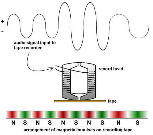
Analog Recording and Playback on Magnetic Tape
In recent decades magnetic recording has become the most popular of all recording technologies, mainly because of the ease with which magnetic signals can be recorded, edited, copied, erased, or rerecorded. When an electric current flows in a coil of wire, it generates a magnetic field. Conversely, when a magnetic field moves near a wire, it generates an electric current in the wire. These physical phenomena are the basis of audio tape recording (conversion of an electrical signal to a magnetic pattern) and playback (conversion of the magnetic pattern back to an electrical signal).
A tape recorder consists of two systems: a tape transport mechanism that moves the tape past the heads at a uniform speed; and record and playback electronics that prepare the signal for recording and then amplify it in playback.
Magnetic recording and reproducing
The actual recording or playback is done by a "head," a small electromagnet mounted in a shielded case. For recording, the signal current generates a magnetic field in the head that is imposed on the magnetic particles in the tape. For playback, the magnetic fields in the moving tape generate tiny electric currents in the head. At each instant the head is in magnetic contact with a very small area of tape (in an audio cassette, that area is about 0.0001 inch wide by 0.02 inch high) containing several thousand particles. Some recorders have separate heads for recording and playback.
Each microscopic particle of iron oxide is an individual bar magnet oriented lengthwise on the tape, with a north pole and a south pole. In an unrecorded tape, about half of the particles are magnetized with their north pole forward, and the other half are oriented with their south pole leading. When exposed to a magnetic field strong enough to overcome their "coercivity" (resistance to change), the particles adopt the imposed field direction, reversing poles if necessary. Thus, the process of recording is simply one of flipping each particle's magnetic orientation one way or the other. Once set, the particles keep their magnetic orientation until exposed to another strong field. (For analog recording, the audio signal is combined with a strong "AC bias" signal that alternates from north to south and back around 100 KHz.) The result is that the audio waveform is faithfully represented by the percentage of north forward particles at each location along the recorded track.
To erase a recording, an "erase head" exposes the tape to a version of the bias signal, whose rapid polarity reversals leave half of the particles magnetized in each direction.
Audio Consoles
Let's now turn to the nerve centre of the entire operation - the console. It's here that signals flowing from mics, turntables, tape recorders and players are amplified, mixed, balanced and routed to air or tape.
At first glance, consoles may look threatening. They're really not - and they all operate on quite basic principles. They can be considered to have three basic systems: input, output and monitoring. As we go through a typical audio board, keep in mind three points: we have to get the signals from each sound source to inputs on the console; combine them; and monitor what we're doing.
We'll look at a single channel of the console, or "strip."
Input Selection
On most consoles, there is an ability to select from two different inputs on a given audio "strip". Unfortunately, you only get to choose one of these sources at a time to work with.
Level Setting
If it's a microphone you've chosen, its low level will have to be amplified to what we call "line level", so each strip contains a microphone preamplifier, which can be switched in and out of the line.
Equalizers
An equalizer is a device that alters a sound by boosting or reducing selected frequencies. We usually have one of these on every fader in our console (except for the submasters and masters). More on these later on in this chapter.
More Level Setting
We have managed to get all inputs up to what is called "line level," but we now need a way to vary the levels of the different sources. Enter the fader...or potentiometer...or pot...or attenuator...or gain control...or, if you insist, volume control. In principle, it's not much more sophisticated than a knob or sliding fader, like on your stereo system, except that it has calibrations on it.
Auxiliary Sends
These are rather like submasters, with two exceptions.
First, you can change the level going to the auxiliary output from each strip's source, regardless of the position of the fader for that strip. You also can decide whether to send the strip's source straight away, before you've used the fader to adjust its level, or after the fader. This selection is called "pre-fade" or "post-fade."
Second, auxiliaries don't normally go to air - they're used for operations like sending sources to control room or studio floor monitors, sending special material to the earpieces that on-camera talent are wearing, and sending information to telephone callers for phone-in shows.
A typical audio console (featuring one strip)
| Analog Recording and Playback on Magnetic Tape
In recent decades magnetic recording has become the most popular of all recording technologies, mainly because of the ease with which magnetic signals can be recorded, edited, copied, erased, or rerecorded. When an electric current flows in a coil of wire, it generates a magnetic field. Conversely, when a magnetic field moves near a wire, it generates an electric current in the wire. These physical phenomena are the basis of audio tape recording (conversion of an electrical signal to a magnetic pattern) and playback (conversion of the magnetic pattern back to an electrical signal).
A tape recorder consists of two systems: a tape transport mechanism that moves the tape past the heads at a uniform speed; and record and playback electronics that prepare the signal for recording and then amplify it in playback.
|
|
Magnetic recording and reproducing
|
Audio Consoles
Let's now turn to the nerve centre of the entire operation - the console. It's here that signals flowing from mics, turntables, tape recorders and players are amplified, mixed, balanced and routed to air or tape.
At first glance, consoles may look threatening. They're really not - and they all operate on quite basic principles. They can be considered to have three basic systems: input, output and monitoring. As we go through a typical audio board, keep in mind three points: we have to get the signals from each sound source to inputs on the console; combine them; and monitor what we're doing.
We'll look at a single channel of the console, or "strip."
Input Selection
On most consoles, there is an ability to select from two different inputs on a given audio "strip". Unfortunately, you only get to choose one of these sources at a time to work with.
Level Setting
If it's a microphone you've chosen, its low level will have to be amplified to what we call "line level", so each strip contains a microphone preamplifier, which can be switched in and out of the line.
Equalizers
An equalizer is a device that alters a sound by boosting or reducing selected frequencies. We usually have one of these on every fader in our console (except for the submasters and masters). More on these later on in this chapter.
More Level Setting
We have managed to get all inputs up to what is called "line level," but we now need a way to vary the levels of the different sources. Enter the fader...or potentiometer...or pot...or attenuator...or gain control...or, if you insist, volume control. In principle, it's not much more sophisticated than a knob or sliding fader, like on your stereo system, except that it has calibrations on it.
Auxiliary Sends
These are rather like submasters, with two exceptions.
First, you can change the level going to the auxiliary output from each strip's source, regardless of the position of the fader for that strip. You also can decide whether to send the strip's source straight away, before you've used the fader to adjust its level, or after the fader. This selection is called "pre-fade" or "post-fade."
Second, auxiliaries don't normally go to air - they're used for operations like sending sources to control room or studio floor monitors, sending special material to the earpieces that on-camera talent are wearing, and sending information to telephone callers for phone-in shows.
| |
|
A typical audio console (featuring one strip)
|
Solo and Pre-Fade Listen
This type of button allows you to listen to a single channel off-line, sometimes through a special "cue" speaker and amplifier, and sometimes through the main monitor speakers, overriding any existing program material on those monitors.
On-Off or Mute
At times, we'll want to electrically separate the sound source from the board. So, we'll usually find a channel on-off key on each strip.
Professional audio operators do not use the strip's mute button to select sources while they are on air! All sources should be mixed using the main faders. This means that words and music will not accidentally be clipped by slow-moving operator's hands, or by unexpected cues. As well, in the heat of the moment, it is much easier to see if an audio strip is activated by looking at the larger faders on the board, instead of having to search for a tiny mute button, or a mute indicator light.
Phase Button
Normally, stereo audio signals are mixed together and laid down on audio tracks "in phase." Electronic transmission of sound is a series of voltage level waves. If a sound appears on two channels, and those channels are mixed , the sounds should "add up." If, for some reason, one channel is "out of phase" with respect to the other, the sounds cancel.
How could one channel ever get "out of phase" with the other in the first place? Consider that broadcast audio is a balanced system; two wires carry the signal, and a third is a ground connection. If somewhere in all the audio interconnections, those two signal wires are reversed in one of the channels, that signal will now be out of phase relative to the other channel. The obvious way to correct an electrical out of phase condition is to rewire the equipment properly. If there is no time for that, most consoles have a phase reversal switch that shifts one channel's phase by 180 degrees, back into phase.
Pan Pots
These allow us to shift the balance of sound to any point between the left and right channels of our stereo consoles.
Tying It All Together
We can make this "tying together" operation easy (but less flexible) or more difficult (but more versatile). If we bring all outputs to one final fader, that one becomes the "master" fader, controlling all of our sources to air. We also can group our sources together in "bunches," each bunch going to a separate "submaster" fader, which in turn, is bundled with the other submasters into the master. This submastering route allows us to vary sound elements in groups - for example, all the microphones, all of the VTR and line sources, "the band," or any other combination you'd like.
Keeping An Eye On Things
If our signals are too strong, they will overload equipment. If they are too weak, they will not overpower the background noise element in our electronics. We need an indicator.
There are many different types of audio level meters, but the most common one is the VU meter (VU stands for volume unit). The VU meter is an "averaging" meter in that it doesn't respond to sudden peaks in level - sort of like your ears. You can get VU meters in the standard, needle movement form, or as an LED or LCD display. They are calibrated in a scale that ranges typically from -20 VU to + 3 VU.
VU meter
PPM meter

Another meter commonly used in Europe (and increasingly, in North America) is the PPM (peak program meter). This device reads peaks in level rather than averages. The argument goes that although humans may not hear momentary peaks in loudness, the equipment does. Therefore, the PPM is better insurance against signal distortion.
LED peak reading meter
Keeping An Eye On Things
If our signals are too strong, they will overload equipment. If they are too weak, they will not overpower the background noise element in our electronics. We need an indicator.
There are many different types of audio level meters, but the most common one is the VU meter (VU stands for volume unit). The VU meter is an "averaging" meter in that it doesn't respond to sudden peaks in level - sort of like your ears. You can get VU meters in the standard, needle movement form, or as an LED or LCD display. They are calibrated in a scale that ranges typically from -20 VU to + 3 VU.
| | |
|
VU meter
|
PPM meter
|
| | Another meter commonly used in Europe (and increasingly, in North America) is the PPM (peak program meter). This device reads peaks in level rather than averages. The argument goes that although humans may not hear momentary peaks in loudness, the equipment does. Therefore, the PPM is better insurance against signal distortion. |
|
LED peak reading meter
|
When mixing audio, "ride the gain" so the level stays between -5 and 0 VU; ride a PPM meter at +8 dBm. It's normal for peaks and dips to go beyond this, of course. Mix with a light, fluid hand. Pots should not be jerked up and down to make adjustments at the slightest fall or rise in loudness. Changes should be smooth - you'll hear abrupt ones. Once again, this is another good reason to use the faders to activate channels, instead of the mute buttons.
Don't We Get To Hear It?
This part's easy. Take a tap off the master (or, using a selector switch, any of the submasters), and amplify it enough to drive loudspeakers. Perhaps put a level pot in the circuit so we can turn it down (or up!) when we want to. That should do the job. One precaution to be taken, however: many such circuits incorporate "mute" systems so when certain microphones' faders are actuated (or when an external mute switch is pressed), the audio at the speakers is automatically cut off. This prevents the dreaded feedback.
An Additional Extra - The Tone Oscillator
This is a signal generator that produces pure sine wave tones at selected frequencies. It is used to calibrate the console to connected tape recorders so their VU meters indicate the same levels, and to put reference tone levels on tape recordings.
A Bit More About Equalizers
Perhaps the most often used signal processor is the equalizer. Your home stereo system's bass and treble controls are primitive equalizers. There are three types in general use in broadcast - selectively variable (fixed frequency), continuously variable (parametric), and graphic. Their jobs are all the same: boost or cut the level of a selected frequency, or set of frequencies.
High Pass, Low Pass, Band Pass Filters
A high pass filter allows you to select a frequency below which signals will be removed, thus passing higher frequencies.
A low pass filter, as you might expect, allows you to select a frequency above which signals will be removed, thus passing lower frequencies.
It is disconcerting for newcomers to the audio operating scene to find that high pass filter controls have figures on them corresponding to low frequencies, and low pass filters having numbers relating to high frequencies!
A band pass filter allows you to select two frequencies - one below and one above which signals will be removed, thus leaving you with a band of frequencies that will be sent onwards.
Selectively Variable Equalizer
This unit is a series of band pass filters, and provides two or three ranges (or bands) of the frequency spectrum that you can vary. You can change where in each range (low, mid, high) you want to affect, and by how much boost or cut.
Selectively variable equalizer, featuring low cut, high pass, band pass, and low pass filters
| | A Bit More About Equalizers
Perhaps the most often used signal processor is the equalizer. Your home stereo system's bass and treble controls are primitive equalizers. There are three types in general use in broadcast - selectively variable (fixed frequency), continuously variable (parametric), and graphic. Their jobs are all the same: boost or cut the level of a selected frequency, or set of frequencies.
High Pass, Low Pass, Band Pass Filters
A high pass filter allows you to select a frequency below which signals will be removed, thus passing higher frequencies.
A low pass filter, as you might expect, allows you to select a frequency above which signals will be removed, thus passing lower frequencies.
It is disconcerting for newcomers to the audio operating scene to find that high pass filter controls have figures on them corresponding to low frequencies, and low pass filters having numbers relating to high frequencies!
A band pass filter allows you to select two frequencies - one below and one above which signals will be removed, thus leaving you with a band of frequencies that will be sent onwards.
Selectively Variable Equalizer
This unit is a series of band pass filters, and provides two or three ranges (or bands) of the frequency spectrum that you can vary. You can change where in each range (low, mid, high) you want to affect, and by how much boost or cut.
|
|
Selectively variable equalizer, featuring low cut, high pass, band pass, and low pass filters
|
Parametric Equalizer
This unit is similar to the selectively variable equalizer mentioned above, but you also can select how narrow (or wide) you want the band affected to be. This is known as affecting its "Q."
Graphic Equalizer
These are nifty looking units that allow you to "draw" on the front panel, by using a series of sliders, the frequency response you wish to achieve. The more sliders you have, the more delicately you can control your output - but the more expensive the unit becomes.
Graphic equalizer
Graphic Equalizer
These are nifty looking units that allow you to "draw" on the front panel, by using a series of sliders, the frequency response you wish to achieve. The more sliders you have, the more delicately you can control your output - but the more expensive the unit becomes.
| |
|
Graphic equalizer
|
Things To Think About:
There's a relationship between the pitch of a sound, its frequency, and its wavelength.
Microphones and speakers work on similar, but opposite principles.
There are four common types of storage media currently used for sound recording, and three common forms of signal recording.
What are the basic principles behind analog and digital recording and reproducing?
Be familiar with some of the most common elements of a broadcast audio console.
Filtering is an integral part of radio and television signal processing. Acquaint yourself with the various filter types and their usage.
What you have written in this post is exactly what I have experience when I first started my blog.I’m happy that I came across with your site this article is on point,thanks again and have a great day.Keep update more information.
BalasHapusDocument Management Software
Electronic Document Management System
Cloud Document Management System
Document Management System
Electronic Document Management Software
Magnetic levitation is the latest in transportation technology and has been the interest of many countries around the world.
BalasHapusThanks
Magnetic Tracks, Magnetic lights & Acessories in Dubai
LED Module & Housing for Spot or Downlight lights in dubai
Magnetic track lighting is a great way to save energy and money in your home. At Savingenergytech.com, you'll find a variety of energy-saving and eco-friendly lighting products, including magnetic track lighting.
BalasHapusThanks
Magnetic Track lighting