Basic electronic for electronic development on Automotive smoothing sensor to intake computer UPS AMNIMARJESLOW GOVERNMENT 91220017 LOR LINTAKE LCLAR CYCLOTRON LJBUSAF
Electronic engineers play a vital role in almost all aspects of our everyday life and are the power behind the 'information revolution' that is increasingly impacting on all our lives.
Electronic engineers hold a pivotal role in the design and manufacture of a vast range of products and systems from smart phones to communications satellites and from personal computers to medical diagnostic systems. These have been made possible by a remarkable combination of scientific and technical innovations that encompass both the design and development of physical systems (hardware) and in many cases the programs that define their operation (software).
All Electronic engineers need analytical, design, information technology and management skills
Introduction: Basic Electronics
Step 1: Electricity
There are two types of electrical signals , those being alternating current (AC), and direct current (DC).
With alternating current, the direction electricity flows throughout the circuit is constantly reversing. You may even say that it is alternating direction. The rate of reversal is measured in Hertz, which is the number of reversals per second. So, when they say that the US power supply is 60 Hz, what they mean is that it is reversing 120 times per second (twice per cycle).
With Direct Current, electricity flows in one direction between power and ground. In this arrangement there is always a positive source of voltage and ground (0V) source of voltage. You can test this by reading a battery with a multimeter.
Speaking of voltage, electricity is typically defined as having a voltage and a current rating. Voltage is obviously rated in Volts and current is rated in Amps. For instance, a brand new 9V battery would have a voltage of 9V and a current of around 500mA (500 milliamps).
Electricity can also be defined in terms of resistance and watts. We will talk a little bit about resistance in the next step, but I am not going to be going over Watts in depth. As you delve deeper into electronics you will encounter components with Watt ratings. It is important to never exceed the Wattage rating of a component, but fortunately that Wattage of your DC power supply can easily be calculated by multiplying the voltage and current of your power source.
Most basic electronic circuits use DC electricity. As such, all further discussion of electricity will revolve around DC electricity.
Step 2: Circuits
A circuit is a complete and closed path through which electric current can flow. In other words, a closed circuit would allow the flow of electricity between power and ground. An open circuit would break the flow of electricity between power and ground.
Anything that is part of this closed system and that allows electricity to flow between power and ground is considered to be part of the circuit.
Step 3: Resistance
The next very important consideration to keep in mind is that electricity in a circuit must be used.
For instance, in the circuit above, the motor that electricity is flowing through is adding resistance to the flow of electricity. Thus, all of the electricity passing through the circuit is being put to use.
In other words, there needs to be something wired between positive and ground that adds resistance to the flow of electricity and uses it up. If positive voltage is connected directly to ground and does not first pass through something that adds resistance, like a motor, this will result in a short circuit. This means that the positive voltage is connected directly to ground.
Likewise, if electricity passes through a component (or group of components) that does not add enough resistance to the circuit, a short will likewise occur .
Shorts are bad because they will result in your battery and/or circuit overheating, breaking, catching on fire, and/or exploding.
It is very important to prevent short circuits by making sure that the positive voltage is never wired directly to ground.
That said, always keep in mind that electricity always follows the path of least resistance to ground. What this means is that if you give positive voltage the choice to pass through a motor to ground, or follow a wire straight to ground, it will follow the wire because the wire provides the least resistance. This also means that by using the wire to bypass the source of resistance straight to ground, you have created a short circuit. Always make sure that you never accidentally connect positive voltage to ground while wiring things in parallel.
Also note that a switch does not add any resistance to a circuit and simply adding a switch between power and ground will create a short circuit.
Step 4: Series Vs. Parallel
There are two different ways in which you can wire things together called series and parallel.
When things are wired in series, things are wired one after another, such that electricity has to pass through one thing, then the next thing, then the next, and so on.
In the first example, the motor, switch and battery are all wired in series because the only path for electricity to flow is from one, to the next, and to the next.
When things are wired in parallel, they are wired side by side, such that electricity passes through all of them at the same time, from one common point to another common point
In the next example, the motors are wired in parallel because the electricity passes through both motors from one common point to another common point.
in the final example the motors are wired in parallel, but the pair of parallel motors, switch and batteries are all wired in series. So, the current is split between the motors in a parallel fashion, but still must pass in series from one part of the circuit to the next.
If this does not make sense yet, do not worry. When you start to build your own circuits, all of this will start to become clear.
Step 5: Basic Components
In order to build circuits, you will need to become familiar with a few basic components. These components may seem simple, but are the bread and butter of most electronics projects. Thus, by learning about these few basic parts, you will be able to go a long way.
Bear with me as I elaborate as to what each of these are in the coming steps.
Step 6: Resistors
As the name implies, resistors add resistance to the circuit and reduces the flow of electrical current. It is represented in a circuit diagram as a pointy squiggle with a value next to it.
The different markings on the resistor represent different values of resistance. These values are measured in ohms.
Resistors also come with different wattage ratings. For most low-voltage DC circuits, 1/4 watt resistors should be suitable.
You read the values from left to right towards the (typically) gold band. The first two colors represent the resistor value, the third represents the multiplier, and the fourth (the gold band) represents the tolerance or precision of the component. You can tell the value of each color by looking at a resistor color value chart.
Anyhow... a resistor with the markings brown, black, orange, gold will translate as follows:
1 (brown) 0 (black) x 1,000 = 10,000 with a tolerance of +/- 5%
Any resistor of over 1000 ohms is typically shorted using the letter K. For instance, 1,000 would be 1K; 3,900, would translate to 3.9K; and 470,000 ohms would become 470K.
Values of ohms over a million are represented using the letter M. In this case, 1,000,000 ohms would become 1M.
Step 7: Capacitors
A capacitor is a component that stores electricity and then discharges it into the circuit when there is a drop in electricity. You can think of it as a water storage tank that releases water when there is a drought to ensure a steady stream.
Capacitors are measured in Farads. The values that you will typically encounter in most capacitors are measured in picofarad (pF), nanofarad (nF), and microfarad (uF). These are often used interchangeably and it helps to have a conversion chart at hand.
The most commonly encountered types of capacitors are ceramic disc capacitors that look like tiny M&Ms with two wires sticking out of them and electrolytic capacitors that look more like small cylindrical tubes with two wires coming out the bottom (or sometimes each end).
Ceramic disc capacitors are non-polarized, meaning that electricity can pass through them no matter how they are inserted in the circuit. They are typically marked with a number code which needs to be decoded. This type of capacitor is typically represented in a schematic as two parallel lines.
Electrolytic capacitors are typically polarized. This means that one leg needs to be connected to the ground side of the circuit and the other leg must be connected to power. If it is connected backwards, it won't work correctly. Electrolytic capacitors have the value written on them, typically represented in uF. They also mark the leg which connects to ground with a minus symbol (-). This capacitor is represented in a schematic as a side-by-side straight and curved line. The straight line represents the end which connects to power and the curve connected to ground.
Step 8: Diodes
Diodes are components which are polarized. They only allow electrical current to pass through them in one direction. This is useful in that it can be placed in a circuit to prevent electricity from flowing in the wrong direction.
Another thing to keep in mind is that it requires energy to pass through a diode and this results in a drop of voltage. This is typically a loss of about 0.7V. This is important to keep in mind for later when we talk about a special form of diodes called LEDs.
The ring found on one end of the diode indicates the side of the diode which connects to ground. This is the cathode. It then follows that the other side connects to power. This side is the anode.
The part number of the diode is typically written on it, and you can find out its various electrical properties by looking up its datasheet.
They are represented in schematic as a line with a triangle pointing at it. The line is that side which connected to ground and the bottom of the triangle connects to power.
Step 9: Transistors
A transistor takes in a small electrical current at its base pin and amplifies it such that a much larger current can pass between its collector and emitter pins. The amount of current that passes between these two pins is proportional to the voltage being applied at the base pin.
There are two basic types of transistors, which are NPN and PNP. These transistors have opposite polarity between collector and emitter.
NPN transistors allow electricity to pass from the collector pin to the emitter pin. They are represented in a schematic with a line for a base, a diagonal line connecting to the base, and a diagonal arrow pointing away from the base.
PNP transistors allow electricity to pass from the emitter pin to the collector pin. They are represented in a schematic with a line for a base, a diagonal line connecting to the base, and a diagonal arrow pointing towards the base.
Transistors have their part number printed on them and you can look up their datasheets online to learn about their pin layouts and their specific properties. Be sure to take note of the transistor's voltage and current rating as well.
Step 10: Integrated Circuits
An integrated circuit is an entire specialized circuit that has been miniaturized and fit onto one small chip with each leg of the chip connecting to a point within the circuit. These miniaturized circuits typically consist of components such as transistors, resistors, and diodes.
For instance, the internal schematic for a 555 timer chip has over 40 components in it.
Like transistors, you can learn all about integrated circuits by looking up their datasheets. On the datasheet you will learn the functionality of each pin. It should also state the voltage and current ratings of both the chip itself and each individual pin.
Integrated circuits come in a variety of different shapes and sizes. As a beginner, you will be mainly working with DIP chips. These have pins for through-hole mounting. As you get more advanced, you may consider SMT chips which are surface mount soldered to one side of a circuit board.
The round notch on one edge of the IC chip indicates the top of the chip. The pin to the top left of the chip is considered pin 1. From pin 1, you read sequentially down the side until you reach the bottom (i.e. pin 1, pin 2, pin 3..). Once at the bottom, you move across to the opposite side of the chip and then start reading the numbers up until you reach the top again.
Keep in mind that some smaller chips have a small dot next to pin 1 instead of a notch at the top of the chip.
There is no standard way that all ICs are incorporated into circuit diagrams, but they are often represented as boxes with numbers in them (the numbers representing the pin number).
Step 11: Potentiometers
Potentiometers are variable resistors. In plain English, they have some sort of knob or slider that you turn or push to change resistance in a circuit. If you have ever used a volume knob on a stereo or a sliding light dimmer, then you have used a potentiometer.
Potentiometers are measured in ohms like resistors, but rather than having color bands, they have their value rating written directly on them (i.e. "1M"). They are also marked with an "A" or a "B, " which indicated the type of response curve it has.
Potentiometers marked with a "B" have a linear response curve. This means that as you turn the knob, the resistance increases evenly (10, 20, 30, 40, 50, etc.). The potentiometers marked with an "A" have a logarithmic response curve. This means that as you turn the knob, the numbers increase logarithmically (1, 10, 100, 10,000 etc.)
Potentiometers have three legs as to create a voltage divider, which is basically two resistors in series. When two resistors are put in series, the point between them is a voltage that is a value somewhere between the source value and ground.
For instance, if you have two 10K resistors in series between power (5V) and ground (0V), the point where these two resistors meet will be half the power supply (2.5V) because both of the resistors have identical values. Assuming this middle point is actually the center pin of a potentiometer, as you turn the knob, the voltage on the middle pin will actually increase towards 5V or decrease toward 0V (depending which direction that you turn it). This is useful for adjusting the intensity of an electrical signal within a circuit (hence its use as a volume knob).
This is represented in a circuit as a resistor with an arrow pointing towards the middle of it.
If you only connect one of the outer pins and the center pin to the circuit, you are only changing the resistance within the circuit and not the voltage level on the middle pin. This too is a useful tool for circuit building because often you just want to change the resistance at a particular point and not create an adjustable voltage divider.
This configuration is often represented in a circuit as a resistor with an arrow coming out of one side and looping back in to point towards the middle.
Step 12: LEDs
LED stands for light emitting diode. It is basically a special type of diode that lights up when electricity passes through it. Like all diodes, the LED is polarized and electricity is only intended to pass through in one direction.
There are typically two indicators to let you know what direction electricity will pass through and LED. The first indicator that the LED will have a longer positive lead (anode) and a shorter ground lead (cathode). The other indicator is a flat notch on the side of the LED to indicate the positive (anode) lead. Keep in mind that not all LEDs have this indication notch (or that it is sometimes wrong).
Like all diodes, LEDs create a voltage drop in the circuit, but typically do not add much resistance. In order to prevent the circuit from shorting, you need to add a resistor in series. To figure out how large of a resistor you need for optimum intensity, you can use this online LED calculator to figure out how much resistance is needed for a single LED. It is often good practice to use a resistor that is slightly larger in the value than what is returned by calculator.
You may be tempted to wire LEDs in series, but keep in mind that each consecutive LED will result in a voltage drop until finally there is not enough power left to keep them lit. As such, it is ideal to light up multiple LEDs by wiring them in parallel. However, you need to make certain that all of the LEDs have the same power rating before you do this (different colors often are rated differently).
LEDs will show up in a schematic as a diode symbol with lightning bolts coming off of it, to indicate that it is a glowing diode.
Step 13: Switches
A switch is basically a mechanical device that creates a break in a circuit. When you activate the switch, it opens or closes the circuit. This is dependent on the type of switch it is.
Normally open (N.O.) switches close the circuit when activated.
Normally closed (N.C.) switches open the circuit when activated.
As switches get more complex they can both open one connection and close another when activated. This type of switch is a single-pole double-throw switch (SPDT).
If you were to combine two SPDT switches into one single switch, it would be called a double-pole double-throw switch (DPDT). This would break two separate circuits and open two other circuits, every time the switch was activated.
Step 14: Batteries
A battery is a container which converts chemical energy into electricity. To over-simplify the matter, you can say that it "stores power."
By placing batteries in series you are adding the voltage of each consecutive battery, but the current stays the same. For instance, a AA-battery is 1.5V. If you put 3 in series, it would add up to 4.5V. If you were to add a fourth in series, it would then become 6V.
By placing batteries in parallel the voltage remains the same, but the amount of current available doubles. This is done much less frequently than placing batteries in series, and is usually only necessary when the circuit requires more current than a single series of batteries can offer.
It is recommend that you get a range of AA battery holders. For instance, I would get an assortment that holds 1, 2, 3, 4, and 8 AA batteries.
Batteries are represented in a circuit by a series of alternating lines of different length. There are also additional marking for power, ground and the voltage rating.
Step 15: Breadboards
Breadboards are special boards for prototyping electronics. They are covered with a grid of holes, which are split into electrically continuous rows.
In the central part there are two columns of rows that are side-by-side. This is designed to allow you to be able to insert an integrated circuit into the center. After it is inserted, each pin of the integrated circuit will have a row of electrically continuous holes connected to it.
In this way, you can quickly build a circuit without having to do any soldering or twisting wires together. Simply connect the parts that are wired together into one of the electrically continuous rows.
On each edge of the breadboard, there typically runs two continuous bus lines. One is intended as a power bus and the other is intended as a ground bus. By plugging power and ground respectively into each of these, you can easily access them from anywhere on the breadboard.
Step 16: Wire
In order to connect things together using a breadboard, you either need to use a component or a wire.
Wires are nice because they allow you to connect things without adding virtually no resistance to the circuit. This allows you to be flexible as to where you place parts because you can connect them together later with wire. It also allows you to connect a part to multiple other parts.
it is recommended that you use insulated 22awg (22 gauge) solid core wire. You can get this at Radioshack. Red wire typically indicates a power connection and black wire represents a ground connection.
To use wire in your circuit, simply cut a piece to size, strip a 1/4" of insulation from each end of the wire and use it to connect points together on the breadboard.
Parts List:
1K ohm - 1/4 Watt resistor
5mm red LED
SPST toggle switch
9V battery connector
If you look at the schematic you will see that the 1K resistor, LED, and switch are all connected in series with the 9V battery. When you build the circuit, you will be able to turn the LED on and off with the switch.
You can look up the color code for a 1K resistor using the graphical resistance calculator. Also, remember that the LED needs to be plugged in the right way (hint - the long leg goes to the positive side of the circuit).
If you decide to use the switch, open and close it to see what happens when you make and break the circuit.
This next schematic may look daunting, but it is actually rather straight-forward. It is using all of the parts that we have just gone over to automatically blink an LED.
Any general purpose NPN or PNP transistors should do for the circuit, but should you want to follow along at home, I am using 293904 (NPN) and 2N3906 (PNP) transistors. I learned their pin layouts by looking up their datasheets. A good source for quickly finding datasheets is Octopart.com. Simply search for the part number and you should find a picture of the part and link to the datasheet.
For instance, from the datasheet for the 2N3904 transistor, I was quickly able to see that pin 1 was the emitter, pin 2 was the base, and pin 3 was the collector.
Aside from the transistors, all of the resistors, capacitors, and LED should be straight-forward to connect. However, there is one tricky bit in the schematic. Notice the half-arch near the transistor. This arch indicates that the capacitor jumps over the trace from the battery and connects to the base of the PNP transistor instead.
Also, when building the circuit, don't forget to keep in mind that the electrolytic capacitors and LED are polarized and will only work in one direction.
After you finish building the circuit and plug in the power, it should blink. If it does not blink, carefully check all of your connections and orientation of all of the parts.
A trick for quickly debugging the circuit is counting components in the schematic versus components on your breadboard. If they don't match, you left something out. You can also do the same counting trick for the number of things that connect to a particular point in the circuit.
Once it is working, try changing the value of 470K resistor. Notice that by increasing the value of this resistor, the LED blinks slower and that by decreasing it, the LED blinks faster.
The reason for this is that the resistor is controlling the rate at which the 10uF capacitor is filling and discharging. This is directly related to the blinking of the LED.
Replace this resistor with a 1M potentiometer that is in series with a 10K resistor. Wire it such that one side of the resistor connects to an outer pin on the potentiometer and the other side connects to the base of the PNP transistor. The center pin of the potentiometer should connect to ground. The rate of blinking now changes when you turn the knob and sweep through the resistance.
This last circuit is using a 555 timer chip to make noise using a speaker.
What is happening is that the configuration of components and connections on the 555 chip is causing pin 3 to oscillate rapidly between high and low. If you were to graph these oscillations, it would look like a square wave (a wave the alternates between two power levels). This wave then rapidly pulses the speaker, which displaces air at such a high frequency that we hear this as a steady tone of that frequency.
Make sure that the 555 chip is straddling the center of the breadboard, such that none of the pins might get accidentally connected. Aside from that, simply make the connections as specified in the schematic diagram.
Also note the "NC" symbol on the schematic. This stands in for "No Connect," which obviously means nothing connects to that pin in this circuit.
You can read all about 555 chips on this page and see a great selection of additional 555 schematics on this page.
In terms of the speaker, use a small speaker like you might find inside of a musical greeting card. This configuration can't drive a large speaker, the smaller the speaker you can find, the better off that you will be. Most speakers are polarized, so make certain that you have the negative side of the speaker connected to ground (if it requires it).
If you want to take it a step farther, you can create a volume knob by connecting one outer pin of a 100K potentiometer to pin 3, the middle pin to the speaker, and the the remaining outer pin to ground.
Step 20: You're on Your Own
Basic Electronics
The goal of this chapter is to provide some basic information about electronic circuits. We make the assumption that you have no prior knowledge of electronics, electricity, or circuits, and start from the basics. This is an unconventional approach, so it may be interesting, or at least amusing, even if you do have some experience. So, the first question is ``What is an electronic circuit?'' A circuit is a structure that directs and controls electric currents, presumably to perform some useful function. The very name "circuit" implies that the structure is closed, something like a loop. That is all very well, but this answer immediately raises a new question: "What is an electric current?" Again, the name "current" indicates that it refers to some type of flow, and in this case we mean a flow of electric charge, which is usually just called charge because electric charge is really the only kind there is. Finally we come to the basic question:
No one knows what charge really is anymore than anyone knows what gravity is. Both are models, constructions, fabrications if you like, to describe and represent something that can be measured in the real world, specifically a force. Gravity is the name for a force between masses that we can feel and measure. Early workers observed that bodies in "certain electrical condition" also exerted forces on one another that they could measure, and they invented charge to explain their observations. Amazingly, only three simple postulates or assumptions, plus some experimental observations, are necessary to explain all electrical phenomena. Everything: currents, electronics, radio waves, and light. Not many things are so simple, so it is worth stating the three postulates clearly.
We just invent the name to represent the source of the physical force that can be observed. The assumption is that the more charge something has, the more force will be exerted. Charge is measured in units of Coulombs, abbreviated C. The unit was named to honor Charles Augustin Coulomb (1736-1806) the French aristocrat and engineer who first measured the force between charged objects using a sensitive torsion balance he invented. Coulomb lived in a time of political unrest and new ideas, the age of Voltaire and Rousseau. Fortunately, Coulomb completed most of his work before the revolution and prudently left Paris with the storming of the Bastille.
We call the two styles positive charge, , and (you guessed it) negative charge, . Charge also comes in lumps of -19C , which is about two ten-million-trillionths of a Coulomb. The discrete nature of charge is not important for this discussion, but it does serve to indicate that a Coulomb is a LOT of charge.
You cannot create it and you cannot annihilate it. You can, however, neutralize it. Early workers observed experimentally that if they took equal amounts of positive and negative charge and combined them on some object, then that object neither exerted nor responded to electrical forces; effectively it had zero net charge. This experiment suggests that it might be possible to take uncharged, or neutral, material and to separate somehow the latent positive and negative charges. If you have ever rubbed a balloon on wool to make it stick to the wall, you have separated charges using mechanical action.
Those are the three postulates. Now we will present some of the experimental findings that both led to them and amplify their significance.
First we return to the basic assumption that forces are the result of charges. Specifically, bodies with opposite charges attract, they exert a force on each other pulling them together. The magnitude of the force is proportional to the product of the charge on each mass. This is just like gravity, where we use the term "mass" to represent the quality of bodies that results in the attractive force that pulls them together (see Fig. 4.1).
Figure 4.1: Opposite charges exert an attractive force on each other, just like two masses attract. External force is required to hold them apart, and work is required to move them farther apart.
Electrical force, like gravity, also depends inversely on the distance squared between the two bodies; short separation means big forces. Thus it takes an opposing force to keep two charges of opposite sign apart, just like it takes force to keep an apple from falling to earth. It also takes work and the expenditure of energy to pull positive and negative charges apart, just like it takes work to raise a big mass against gravity, or to stretch a spring. This stored or potential energy can be recovered and put to work to do some useful task. A falling mass can raise a bucket of water; a retracting spring can pull a door shut or run a clock. It requires some imagination to devise ways one might hook on to charges of opposite sign to get some useful work done, but it should be possible.
The potential that separated opposite charges have for doing work if they are released to fly together is called voltage, measured in units of volts (V). (Sadly, the unit volt is not named for Voltaire, but rather for Volta, an Italian scientist.) The greater the amount of charge and the greater the physical separation, the greater the voltage or stored energy. The greater the voltage, the greater the force that is driving the charges together. Voltage is always measured between two points, in this case, the positive and negative charges. If you want to compare the voltage of several charged bodies, the relative force driving the various charges, it makes sense to keep one point constant for the measurements. Traditionally, that common point is called "ground."
Early workers, like Coulomb, also observed that two bodies with charges of the same type, either both positive or both negative, repelled each other (Fig. 4.2). They experience a force pushing
Figure 4.2: Like charges exert a repulsive force on each other. External force is required to hold them together, and work is required to push them closer.
them apart, and an opposing force is necessary to hold them together, like holding a compressed spring. Work can potentially be done by letting the charges fly apart, just like releasing the spring. Our analogy with gravity must end here: no one has observed negative mass, negative gravity, or uncharged bodies flying apart unaided. Too bad, it would be a great way to launch a space probe. The voltage between two separated like charges is negative; they have already done their work by running apart, and it will take external energy and work to force them back together.
So how do you tell if a particular bunch of charge is positive or negative? You can't in isolation. Even with two charges, you can only tell if they are the same (they repel) or opposite (they attract). The names are relative; someone has to define which one is "positive." Similarly, the voltage between two points and , AB , is relative. If AB is positive you know the two points are oppositely charged, but you cannot tell if point has positive charge and point negative, or visa versa. However, if you make a second measurement between and another point , you can at least tell if and have the same charge by the relative sign of the two voltages, AB and AC to your common point . You can even determine the voltage between and without measuring it: BC = VAC - VAB . This is the advantage of defining a common point, like , as ground and making all voltage measurements with respect to it. If one further defines the charge at point to be negative charge, then a positive AB means point is positively charged, by definition. The names and the signs are all relative, and sometimes confusing if one forgets what the reference or ground point is.
Charge is mobile and can flow freely in certain materials, called conductors. Metals and a few other elements and compounds are conductors. Materials that charge cannot flow through are called insulators. Air, glass, most plastics, and rubber are insulators, for example. And then there are some materials called semiconductors, that, historically, seemed to be good conductors sometimes but much less so other times. Silicon and germanium are two such materials. Today, we know that the difference in electrical behavior of different samples of these materials is due to extremely small amounts of impurities of different kinds, which could not be measured earlier. This recognition, and the ability to precisely control the "impurities" has led to the massive semiconductor electronics industry and the near-magical devices it produces, including those on your RoboBoard. We will discuss semiconductor devices later; now let us return to conductors and charges.
Imagine two oppositely charged bodies, say metal spheres, that are being held apart, as in Fig. 4.3.
Figure 4.3: Two spheres with opposite charges are connected by a conductor, allowing charge to flow.
There is a force between them, the potential for work, and thus a voltage. Now we connect a conductor between them, a metal wire. On the positively charged sphere, positive charges rush along the wire to the other sphere, repelled by the nearby similar charges and attracted to the distant opposite charges. The same thing occurs on the other sphere and negative charge flows out on the wire. Positive and negative charges combine to neutralize each other, and the flow continues until there are no charge differences between any points of the entire connected system. There may be a net residual charge if the amounts of original positive and negative charge were not equal, but that charge will be distributed evenly so all the forces are balanced. If they were not, more charge would flow. The charge flow is driven by voltage or potential differences. After things have quieted down, there is no voltage difference between any two points of the system and no potential for work. All the work has been done by the moving charges heating up the wire.
The flow of charge is called electrical current. Current is measured in amperes (a), amps for short (named after another French scientist who worked mostly with magnetic effects). An ampere is defined as a flow of one Coulomb of charge in one second past some point. While a Coulomb is a lot of charge to have in one place, an ampere is a common amount of current; about one ampere flows through a 100 watt incandescent light bulb, and a stove burner or a large motor would require ten or more amperes. On the other hand low power digital circuits use only a fraction of an ampere, and so we often use units of of an ampere, a milliamp, abbreviated as ma, and even of a milliamp, or a microamp, . The currents on the RoboBoard are generally in the milliamp range, except for the motors, which can require a full ampere under heavy load. Current has a direction, and we define a positive current from point to as the flow of positive charges in the same direction. Negative charges can flow as well, in fact, most current is actually the result of negative charges moving. Negative charges flowing from to would be a negative current, but, and here is the tricky part, negative charges flowing from to would represent a positive current from to . The net effect is the same: positive charges flowing to neutralize negative charge or negative charges flowing to neutralize positive charge; in both cases the voltage is reduced and by the same amount.
Charges can be separated by several means to produce a voltage. A battery uses a chemical reaction to produce energy and separate opposite sign charges onto its two terminals. As the charge is drawn off by an external circuit, doing work and finally returning to the opposite terminal, more chemicals in the battery react to restore the charge difference and the voltage. The particular type of chemical reaction used determines the voltage of the battery, but for most commercial batteries the voltage is about 1.5 V per chemical section or cell. Batteries with higher voltages really contain multiple cells inside connected together in series. Now you know why there are 3 V, 6 V, 9 V, and 12 V batteries, but no 4 or 7 V batteries. The current a battery can supply depends on the speed of the chemical reaction supplying charge, which in turn often depends on the physical size of the cell and the surface area of the electrodes. The size of a battery also limits the amount of chemical reactants stored. During use, the chemical reactants are depleted and eventually the voltage drops and the current stops. Even with no current flow, the chemical reaction proceeds at a very slow rate (and there is some internal current flow), so a battery has a finite storage or shelf life, about a year or two in most cases. In some types of batteries, like the ones we use for the robot, the chemical reaction is reversible: applying an external voltage and forcing a current through the battery, which requires work, reverses the chemical reaction and restores most, but not all, the chemical reactants. This cycle can be repeated many times. Batteries are specified in terms of their terminal voltage, the maximum current they can deliver, and the total current capacity in ampere-hours.
You should handle batteries carefully, especially the ones we use in this course. Chemicals are a very efficient and compact way of storing energy. Just consider the power of gasoline or explosives, or the fact that you can play soccer for several hours powered only by a slice of cold pizza for breakfast. Never connect the terminals of a battery together with a wire or other good conductor. The battery we use for the RoboBoard is similar to the battery in cars, which uses lead and sulphuric acid as reactants. Such batteries can deliver very large currents through a short circuit, hundreds of amperes. The large current will heat the wire and possibly burn you; the resulting rapid internal chemical reactions also produce heat and the battery can explode, spreading nasty, reactive chemicals about. Charging these batteries with too large a current can have the same effect. Double check the circuit and instructions before connecting a battery to any circuit. More information on batteries can be found in Chapter 7.
We need some way to control the flow of current from a voltage source, like a battery, so we do not melt wires and blow up batteries. If you think of current, charge flow, in terms of water flow, a good electrical conductor is like big water pipe. Water mains and fire hoses have their uses, but you do not want to take a drink from one. Rather, we use small pipes, valves, and other devices to limit water flow to practical levels. Resistors do the same for current; they resist the flow of charge; they are poor conductors. The value of a resistor is measured in ohms and represented by the Greek letter capital omega. There are many different ways to make a resistor. Some are just a coil of wire made of a material that is a poor conductor. The most common and inexpensive type is made from powdered carbon and a glue-like binder. Such carbon composition resistors usually have a brown cylindrical body with a wire lead on each end, and colored bands that indicate the value of the resistor. The key to reading these values is given in Chapter 2.
There are other types of resistors in your robot kit. The potentiometer is a variable resistor. When the knob of a potentiometer is turned, a slider moves along the resistance element. Potentiometers generally have three terminals, a common slider terminal, and one that exhibits increasing resistance and one that has decreasing resistance relative to the slider as the shaft is turned in one direction. The resistance between the two stationary contacts is, of course, fixed, and is the value specified for the potentiometer. The photoresistor or photocell is composed of a light sensitive material. When the photocell is exposed to more light, the resistance decreases. This type of resistor makes an excellent light sensor.
Ohm's law describes the relationship between voltage, , which is trying to force charge to flow, resistance, , which is resisting that flow, and the actual resulting current . The relationship is simple and very basic: . Thus large voltages and/or low resistances produce large currents. Large resistors limit current to low values. Almost every circuit is more complicated than just a battery and a resistor, so which voltage does the formula refer to? It refers to the voltage across the resistor, the voltage between the two terminal wires. Looked at another way, that voltage is actually produced by the resistor. The resistor is restricting the flow of charge, slowing it down, and this creates a traffic jam on one side, forming an excess of charge with respect to the other side. Any such charge difference or separation results in a voltage between the two points, as explained above. Ohm's law tells us how to calculate that voltage if we know the resistor value and the current flow. This voltage drop is analogous to the drop in water pressure through a small pipe or small nozzle.
Current flowing through a poor conductor produces heat by an effect similar to mechanical friction. That heat represents energy that comes from the charge traveling across the voltage difference. Remember that separated charges have the potential to do work and provide energy. The work involved in heating a resistor is not very useful, unless we are making a hotplate; rather it is a byproduct of restricting the current flow. Power is measured in units of watts (W), named after James Watt, the Englishman who invented the steam engine, a device for producing lots of useful power. The power that is released into the resistor as heat can be calculated as , where is the current flowing through the resistor and is the voltage across it. Ohm's law relates these two quantities, so we can also calculate the power as The power produced in a resistor raises its temperature and can change its value or destroy it. Most resistors are air-cooled and they are made with different power handling capacity. The most common values are 1/8, 1/4, 1, and 2 watt resistors, and the bigger the wattage rating, the bigger the resistor physically. Some high power applications use special water cooled resistors. Most of the resistors on the RoboBoard are 1/8 watt.
Resistors are often connected together in a circuit, so it is necessary to know how to determine the resistance of a combination of two or more resistors. There are two basic ways in which resistors can be connected: in series and in parallel. A simple series resistance circuit is shown in Figure 4.4.
Figure 4.4: Two Resistors in Series
Determining the total resistance for two or more resistors in series is very simple. Total resistance equals the sum of the individual resistances. In this case, T=R1+R2 . This makes common sense; if you think again in terms of water flow, a series of obstructions in a pipe add up to slow the flow more than any one. The resistance of a series combination is always greater than any of the individual resistors.
The other method of connecting resistors is shown in Figure 4.5, which shows a simple parallel resistance circuit.
Figure 4.5: Two Resistors in Parallel
Our water pipe analogy indicates that it should be easier for current to flow through this multiplicity of paths, even easier than it would be to flow through any single path. Thus, we expect a parallel combination of resistors to have less resistance than any one of the resistors. Some of the total current will flow through R1 and some will flow through R2, causing an equal voltage drop across each resistor. More current, however, will flow through the path of least resistance. The formula for total resistance in a parallel circuit is more complex than for a series circuit:
T={1{1R1}+{1R2}...+{1Rn}}
(1)
Parallel and series circuits can be combined to make more complex structures, but the resulting complex resistor circuits can be broken down and analyzed in terms of simple series or parallel circuits. Why would you want to use such combinations? There are several reasons; you might use a combination to get a value of resistance that you needed but did not have in a single resistor. Resistors have a maximum voltage rating, so a series of resistors might be used across a high voltage. Also, several low power resistors can be combined to handle higher power. What type of connection would you use?
Capacitors are another element used to control the flow of charge in a circuit. The name derives from their capacity to store charge, rather like a small battery. Capacitors consist of two conducting surfaces separated by an insulator; a wire lead is connected to each surface. You can imagine a capacitor as two large metal plates separated by air, although in reality they usually consist of thin metal foils or films separated by plastic film or another solid insulator, and rolled up in a compact package. Consider connecting a capacitor across a battery, as in Fig. 4.6.
Figure 4.6: A simple capacitor connected to a battery through a resistor.
As soon as the connection is made charge flows from the battery terminals, along the wire and onto the plates, positive charge on one plate, negative charge on the other. Why? The like-sign charges on each terminal want to get away from each other. In addition to that repulsion, there is an attraction to the opposite-sign charge on the other nearby plate. Initially the current is large, because in a sense the charges can not tell immediately that the wire does not really go anywhere, that there is no complete circuit of wire. The initial current is limited by the resistance of the wires, or perhaps by a real resistor, as we have shown in Fig. 4.6. But as charge builds up on the plates, charge repulsion resists the flow of more charge and the current is reduced. Eventually, the repulsive force from charge on the plate is strong enough to balance the force from charge on the battery terminal, and all current stops. Figure 4.7 shows how the current might vary with
Figure 4.7: The time dependence of the current in the circuit of Fig. 4.6 for two values of resistance.
time for two different values of resistors. For a large resistor, the whole process is slowed because the current is less, but in the end, the same amount of charge must exist on the capacitor plates in both cases. The magnitude of the charge on each plate is equal.
The existence of the separated charges on the plates means there must be a voltage between the plates, and this voltage be equal to the battery voltage when all current stops. After all, since the points are connected by conductors, they should have the same voltage; even if there is a resistor in the circuit, there is no voltage across the resistor if the current is zero, according to Ohm's law. The amount of charge that collects on the plates to produce the voltage is a measure of the value of the capacitor, its capacitance, measured in farads (f). The relationship is , where Q is the charge in Coulombs. Large capacitors have plates with a large area to hold lots of charge, separated by a small distance, which implies a small voltage. A one farad capacitor is extremely large, and generally we deal with microfarads (), one millionth of a farad, or picofarads (pf), one trillionth -12) of a farad.
Consider the circuit of Fig. 4.6 again. Suppose we cut the wires after all current has stopped flowing. The charge on the plates is now trapped, so there is still a voltage between the terminal wires. The charged capacitor looks somewhat like a battery now. If we connected a resistor across it, current would flow as the positive and negative charges raced to neutralize each other. Unlike a battery, there is no mechanism to replace the charge on the plates removed by the current, so the voltage drops, the current drops, and finally there is no net charge left and no voltage differences anywhere in the circuit. The behavior in time of the current, the charge on the plates, and the voltage looks just like the graph in Fig. 4.7. This curve is an exponential function: . The voltage, current, and charge fall to about 37% of their starting values in a time of seconds, which is called the characteristic time or the time constant of the circuit. The time constant is a measure of how fast the circuit can respond to changes in conditions, such as attaching the battery across the uncharged capacitor or attaching a resistor across the charged capacitor. The voltage across a capacitor cannot change immediately; it takes time for the charge to flow, especially if a large resistor is opposing that flow. Thus, capacitors are used in a circuit to damp out rapid changes of voltage.
Like resistors, capacitors can be joined together in two basic ways: parallel and series. It should be obvious from the physical construction of capacitors that connecting two together in parallel results in a bigger capacitance value. A parallel connection results in bigger capacitor plate area, which means they can hold more charge for the same voltage. Thus, the formula for total capacitance in a parallel circuit is:
T=C1+C2...+Cn ,
(2)
the same form of equation for resistors in series, which can be confusing unless you think about the physics of what is happening.
The capacitance of a series connection is lower than any capacitor because for a given voltage across the entire group, there will be less charge on each plate. The total capacitance in a series circuit is
T={1{1C1}+{1C2}...+{1Cn}}.
(3)
Again, this is easy to confuse with the formula for parallel resistors, but there is a nice symmetry here.
Inductors are the third and final type of basic circuit component. An inductor is a coil of wire with many windings, often wound around a core made of a magnetic material, like iron. The properties of inductors derive from a different type of force than the one we invented charge to explain: magnetic force rather than electric force. When current flows through a coil (or any wire) it produces a magnetic field in the space outside the wire, and the coil acts just like any natural, permanent magnet, attracting iron and other magnets. If you move a wire through a magnetic field, a current will be generated in the wire and will flow through the associated circuit. It takes energy to move the wire through the field, and that mechanical energy is transformed to electrical energy. This is how an electrical generator works. If the current through a coil is stopped, the magnetic field must also disappear, but it cannot do so immediately. The field represents stored energy and that energy must go somewhere. The field contracts toward the coil, and the effect of the field moving through the wire of the coil is the same as moving a wire through a stationary field: a current is generated in the coil. This induced current acts to keep the current flowing in the coil; the induced current opposes any change, an increase or a decrease, in the current through the inductor. Inductors are used in circuits to smooth the flow of current and prevent any rapid changes.
The current in an inductor is analogous to the voltage across a capacitor. It takes time to change the voltage across a capacitor, and if you try, a large current flows initially. Similarly, it takes time to change the current through an inductor, and if you insist, say by opening a switch, a large voltage will be produced across the inductor as it tries to force current to flow. Such induced voltages can be very large and can damage other circuit components, so it is common to connect some element, like a resistor or even a capacitor across the inductor to provide a current path and absorb the induced voltage. (Often, a diode, which we will discuss later, is used.)
Inductors are measured in henrys (h), another very big unit, so you are more likely to see millihenries, and microhenries. There are almost no inductors on the RoboBoard, but you will be using some indirectly: the motors act like inductors in many ways. In a sense an electric motor is the opposite of an electrical generator. If current flows through a wire that is in a magnetic field (produced either by a permanent magnet or current flowing through a coil), a mechanical force will be generated on the wire. That force can do work. In a motor, the wire that moves through the field and experiences the force is also in the form of a coil of wire, connected mechanically to the shaft of the motor. This coil looks like and acts like an inductor; if you turn off the current (to stop the motor), the coil will still be moving through the magnetic field, and the motor now looks like a generator and can produce a large voltage. The resulting inductive voltage spike can damage components, such as the circuit that controls the motor current. In the past this effect destroyed a lot of motor controller chips and other RoboBoard components. The present board design contains special diodes that will withstand and safely dissipate the induced voltages -- we hope.
You already know how inductors act in combination because they act just like resistors. Inductance adds in series. This makes physical sense because two coils of wire connected in series just looks like a longer coil. Parallel connection reduces inductance because the current is split between the several coils and the fields in each are thus weaker.
Our statements above about charge are not wrong, but they are simple and incomplete. In order to understand how semiconductor devices work one needs a more complete description of the nature of charge in the real world. Charge does not exist independently; it is carried by subatomic particles. For this discussion we will be concerned primarily with electrons, which carry a negative charge of -19 C , the minimum amount of charge that can exist in isolation. At least, no one has found any smaller amount than this fundamental quantum of charge.
Electrons are one component of atoms and molecules. Atoms are the building blocks out of which all matter is constructed. Atoms bond with each other to form substances. Substances composed of just one type of atom are called elements. For example, copper, gold and silver are all elements; that is, each of them consists of only one type of atom. More complex substances are made up of more than one atom and are known as compounds. Water, which has both hydrogen and oxygen atoms, is such a compound. The smallest unit of a compound is a molecule. A water molecule, for example, contains two hydrogen atoms and one oxygen atom.
Atoms themselves are made up of even smaller components: protons, neutrons and electrons. Protons and neutrons form the nucleus of an atom, while the electrons orbit the nucleus. Protons carry positive charge and electrons carry negative charge; the magnitude of the charge for both particles is the same, one quantum charge, -19 C . Neutrons are not charged. Normally, atoms have the same number of protons and electrons and have no net electrical charge.
Figure 4.8: Structure of an Atom
Electrons that are far from the nucleus are relatively free to move around under the influence of external fields because the force of attraction from the positive charge in the nucleus is weak at large distances. In fact, it takes little force in many cases to completely remove an outer electron from an atom, leaving an ion with a net positive charge. Once free, electrons can move at speeds approaching the speed of light (roughly 670 million miles per hour) through metals, gases and vacuum. They can also become attached to another atom, forming an ion with net negative charge.
Electric current in metal conductors consists of a flow of free electrons. Because electrons have negative charge, the flow of electrons is in a direction opposite to the positive current. Free electrons traveling through a conductor drift until they hit other electrons attached to atoms. These electrons are then dislodged from their orbits and replaced by the formerly free electrons. The newly freed electrons then start the process anew. At the microscopic level, electron flow through a conductor is not a steady stream, like water flowing from a faucet, but rather a series of short bursts.
Semiconductor devices are made primarily of silicon (silicon's element symbol is "Si"). Pure silicon forms rigid crystals because of its four valence (outermost) electron structure -- one Si atom bonds to four other Si atoms forming a very regularly shaped diamond pattern. Figure 4.10 shows part of a silicon crystal structure.
Figure 4.10: A Silicon Crystal Structure
Pure silicon is not a conductor because there are no free electrons; all the electrons are tightly bound to neighboring atoms. To make silicon conducting, producers combine or "dope" pure silicon with very small amounts of other elements like boron or phosphorus. Phosphorus has five outer valence electrons. When three silicon atoms and one phosphorus atom bind together in the basic silicon crystal cell of four atoms, there is an extra electron and a net negative charge. Figure4.11 shows the crystal structure of phosphorus doped silicon.
Figure 4.11: Silicon Doped with Phosphorus
This type of material is called n-type silicon. The extra electron in the crystal cell is not strongly attached and can be released by normal thermal energy to carry current; the conductivity depends on the amount of phosphorus added to the silicon.
Boron has only three valance electrons. When three silicon atoms and one boron atom bind with each other there is a "hole" where another electron would be if the boron atom were silicon; see Fig. 4.12. This gives the crystal cell a positive net charge (referred to as p-type silicon), and the ability to pick up an electron easily from a neighboring cell.
Figure 4.12: Silicon Doped with Boron
The resulting migration of electron vacancies or holes acts like a flow of positive charge through the crystal and can support a current. It is sometimes convenient to refer to this current as a flow of positive holes, but in fact the current is really the result of electrons moving in the opposite direction from vacancy to vacancy.
Both p-type and n-type silicon will conduct electricity just like any conductor; however, if a piece of silicon is doped p-type in one section and n-type in an adjacent section, current will flow in only one direction across the junction between the two regions. This device is called a diode and is one of the most basic semiconductor devices.
A diode is called forward biased if it has a positive voltage across it from from the p- to n-type material. In this condition, the diode acts rather like a good conductor, and current can flow, as in Fig. 4.13.
Figure 4.13: A Forward Biased Diode
There will be a small voltage across the diode, about 0.6 volts for Si, and this voltage will be largely independent of the current, very different from a resistor.
If the polarity of the applied voltage is reversed, then the diode will be reverse biased and will appear nonconducting (Fig. 4.14). Almost no current will flow and there will be a large voltage across the device.
Figure 4.14: A Reverse Biased Diode
The non-symmetric behavior is due to the detailed properties of the pn-junction. The diode acts like a one-way valve for current and this is a very useful characteristic. One application is to convert alternating current (AC), which changes polarity periodically, into direct current (DC), which always has the same polarity. Normal household power is AC while batteries provide DC, and converting from AC to DC is called rectification. Diodes are used so commonly for this purpose that they are sometimes called rectifiers, although there are other types of rectifying devices. Figure 4.15 shows the input and output current for a simple half-wave
Figure 4.15: A Half-Wave Rectifier
rectifier. The circuits gets its name from the fact that the output is just the positive half of the input waveform. A full-wave rectifier circuit (shown in Figure 4.16) uses four diodes arranged so that both polarities of the input waveform can be used at the output.
Figure 4.16: A Full-Wave Rectifier
The full-wave circuit is more efficient than the half-wave one.
explain electronic :
Current Sensor ICs
Allegro MicroSystems, LLC has developed a line of fully integrated Hall-effect current sensor and Hall-effect linear integrated circuits that provide highly accurate, low noise output voltage signals that are proportional to an applied AC or DC current. These ICs are in high volume production in many applications, including automotive HEV inverters and electronic power steering (EPS) systems, and in industrial and consumer inverters and motor control applications.
Allegro current sensor ICs are also used in many power monitoring applications, such as computer blade servers and server power supplies. Allegro's proprietary fully integrated Hall-effect current sensor ICs employ advanced IC and packaging techniques for sensing current from 0 A to 50 A and 50 A to 200 A. These integrated solutions provide galvanic isolation (up to 4.8 kV) and extremely low resistance on the primary conductor (≤ 1mΩ) for highly efficient solutions and are available in a variety of surface mount and through-hole packages. For sensing beyond 200 A, an Allegro linear current sensor IC can be used.
Allegro current sensor ICs allow design engineers to use Hall-effect-based current sensor ICs in new applications where increased energy efficiency or new operating features are required.
Magnetic Digital Position Sensor ICs
Innovation Everywhere: Digital Hall-Effect Sensor ICs, Magnetic Position Sensor ICs, Magnetic Hall Sensor ICs
Hall-effect digital position sensor ICs detect changes in magnetic flux density, allowing them to distinguish movement and position. These contactless sensing solutions require few external components and can withstand the hostile operating conditions of automotive applications. Allegro has the industry’s broadest portfolio of magnetic digital position sensors with switching and latching solutions to cover just about any application need.
Specific advantages of Allegro’s solutions include:
4× chopper stabilization for superior temperature stability and resistance to physical stress
Low-voltage (3 V) operation
Key performance characteristics specified over the full operating voltage and ambient temperature ranges
Industry-leading jitter performance
Automotive-grade ruggedness (most products are qualified to AEC Q100)
The majority of Allegro’s digital position sensing volume ships into demanding automotive applications, and has a proven quality record and dedication to continuous improvement
Magnetic Linear and Angular Position Sensor ICs
High-Performance Angle Sensor ICs
Allegro MicroSystems is a leader in the design and manufacture of Hall-effect integrated circuits. With its unique silicon fabrication process, Allegro integrates Hall-effect sensor elements and signal processing circuitry into single monolithic silicon devices to yield highly accurate magnetic flux density measurement sensors.
Allegro’s linear position and angle Hall-effect sensor ICs are used extensively in the automotive, industrial, white goods, and consumer markets. With each of these markets they are used in a wide variety of position and angle measurement applications. In automotive electronic power steering systems for example, linear and angle position Hall-effect sensor ICs measure steering wheel angle, torque, and rotational speed. In industrial factory automation markets they are used for proximity and angle detection for hydraulic control valves and joysticks, and in white goods and consumer markets they are used for control and open/closure detection systems.
Allegro offers a rich suite of factory and customer programmable linear Hall-effect sensor ICs, and invests continually in new position and angle sensor products to meet the evolving market needs of its customers.
Magnetic Speed Sensor ICs
Allegro is a market leader for rotational speed and direction detection Hall-effect sensor integrated circuits. Leveraging applications expertise, decades of mixed-signal Hall-effect IC design, and a broad portfolio of patents, Allegro offers solutions tailored to four key automotive applications: camshaft, crankshaft, transmission, and wheel speed (ABS).
Solutions are available in two- or three-wire output interfaces, with or without direction detection, and with or without an integrated back-biasing magnet (needed for applications using a ferrous metal target).
Experience working directly with global OEMs and Allegro’s local support network distributed around the world combine to provide deep technical support for sensor selection and application analysis on our high performance sensing solutions. Unique algorithms have been developed and patented to address application-specific anomalies and are utilized as necessary in our broad selection of Speed and Direction sensor ICs to ensure industry-leading accuracy and robust application performance.
Allegro strives to continuously improve quality performance to stay ahead of the ever-increasing demands of the automotive market.
For non-automotive applications, Allegro has a number of sensor ICs with general purpose speed or speed and direction detection capabilities. These ICs are ideally suited for easy integration into sensing systems and Allegro’s global technical support and Sales are eager to help to ensure a fast and problem-free develop
Motor Driver and Interface ICs
Allegro offers an industry leading portfolio of motor driver and controller ICs for brushless DC, brush DC, and stepper motors. Product architectures vary from highly-efficient internal DMOS drivers to MOSFET controller ICs suited for a wide variety of motor applications. Coupled with a strong system level expertise, Allegro’s motor driver IC portfolio provides the user with a high-performance, leading edge and reliable motor control solution.
Allegro's BCD (bipolar, CMOS and DMOS components) technology allows for a wide range of features that is well suited for today’s demanding motor control applications. Allegro motor driver ICs can be found in a number of demanding markets, including automotive, industrial and office equipment. Our products are found in motor driver applications such as automotive pumps and blowers, electronic power steering (EPS) systems, printers (ink-jet and laser) and a variety of cooling fan applications
Regulators and Lighting
Allegro MicroSystems, LLC offers a growing portfolio of DC/DC switching regulators and LED drivers. Allegro’s process technology and applications expertise has enabled the development of highly integrated ICs, providing flexibility and functionality in a small solution footprint. Devices offer buck, boost, charge pump, and linear topologies and aim to provide comprehensive, extremely robust solutions with minimal external components.
The DC/DC regulator portfolio focuses on fully integrated devices with on-chip FETs, and includes single channel and multiple-output devices. Devices are both general purpose and application specific. The lighting portfolio includes LED driver ICs with a wide variety of topologies, channel counts, output currents and feature sets to help customers optimize their solutions. Drivers are targeted at either LED lighting applications or LED backlighting for LCD displays.
Automotive voltage and temperature ratings are available on devices in both product portfolios.
Electronics Development
Critical Components Selection
The first step of designing the electronics is to select the various microchips (i.e. integrated circuits), sensors, displays, connectors, and other electronic devices needed based upon the desired functions and target retail price of your product.
In the U.S., Digikey, Arrow, Mouser, and Future are the most popular suppliers of electronic components. You can purchase most electronic components in ones (for prototyping and initial testing) or up to thousands (for low-volume manufacturing).
Some examples of electronic components commonly used in product designs.
I recommend creating a detailed system block diagram. Most products require a master microcontroller with various components (displays, sensors, memory, etc) interfacing with the microcontroller via various serial ports. By creating a system block diagram you can easily identify the type and number of serial ports required. This is an essential first step for selecting the correct microcontroller for your product.
The more you learn the better you’ll be able to manage the work done by your engineering team.
Pre-Design Your Product to Estimate Production Cost
I highly recommend that you estimate the production cost for your product before you begin designing the full schematic. In order to do this you’ll need to first create a pre-design of your product.
It’s critical to know as soon as possible how much it will cost to manufacture your product. You need this number in order to determine the best sales price, the cost of inventory, and most importantly how much profit you can make.
Once you’ve selected all of the major components then you should have enough information to accurately estimate the production cost for your product (Cost of Goods Sold – COGS). Most entrepreneurs and developers skip this step and proceed right to designing the full circuit schematic (see my next step). That’s a mistake.
Knowing the production cost (plus the development and scaling costs) is so important that I created the Predictable Hardware Report to do this for new electronic products. This report includes a preliminary design of your product along with accurate estimates on the cost to develop, scale, and manufacture it.
Don’t make profit an after thought. Does Apple start developing a new product before knowing how much profit they can make? Of course not, and neither should you.
See my article describing in great detail all of the costs to develop, prototype, scale, and manufacture (including COGS) your new electronic hardware product.
Circuit Design (Schematic)
The next step is to create a diagram of the electronics design, called a schematic diagram, that is similar to a blueprint for a house. In most cases you’ll need a schematic circuit for each block of your system block diagram.
The schematic shows how every component, from microchips to simple resistors, connects together. Creating the schematic or circuit diagram is the core step in designing electronics.
You’ll need special electronics design software to create the schematic. I highly recommend a package called DipTrace which is really affordable, powerful, and easy to use. There are dozens of electronics design packages available but I’ve found Diptrace to be best to option especially for new designers (although it’s powerful enough to use for really complex designs).
Printed Circuit Board Design
Once the schematic is done you will create the design for the actual Printed Circuit Board (PCB). The PCB is the physical board that holds and connects all of the electronic components. For many projects creating the PCB layout can be the most time consuming step.
The PCB is designed in the same software that created the schematic diagram. The software will have various verification tools to ensure the PCB layout meets the design rules for the PCB process used, and that the PCB matches the schematic.
The smaller the product, and the tighter the components must be packed together, the longer it will take to create the PCB layout. If your product routes large amounts of power, or offers wireless connectivity, then PCB layout is even more critical and time consuming.
For most PCB designs the most critical parts are the power routing, any high-speed signals (crystal clocks, etc) and any wireless circuits.
Bill of Materials (BOM)
The Bill of Materials must now be generated. This is usually automatically created by the schematic design software. The BOM lists the part number, quantity, and all component specifications.
PCB Prototypes
Creating electronic prototypes is a two step process. The first step produces the bare printed circuit boards. Your circuit design software will allow you to output the PCB layout in a format called Gerber with one file for each PCB layer. These Gerber files can be sent to a prototype shop for small volume runs, or the same files can be provided to a larger manufacturer for high volume production.
The second step is having all of the electronic components soldered onto the board. From your design software you’ll be able to output a file that shows the exact coordinates of every component placed on the board. This allows the assembly shop to fully automate the soldering of every component on your PCB.
For producing your assembled boards I highly recommend Seeed Studio Fusion. They offer fantastic pricing on quantities from 5 up to 8,000 boards. They also offer 3D printing services making them a one-stop shop.
I also recommend Sunstone Circuits and San Francisco Circuits which I’ve used extensively to prototype my PCB designs.
Example of a fully assembled Printed Circuit Board (PCB).
It takes 1-2 weeks to get completely assembled boards, unless you pay for rush service which I rarely recommend.
If you really want to squeeze down the size of your PCB then you may want to look at more advanced PCB production methods. Advanced processes have advanced costs, so it’s best to only them use if it is essential for your product’s success.
Evaluate, Debug, and Repeat
Now it’s time to evaluate the prototype of the electronics. Keep in mind that your first prototype will rarely work perfectly. You will most likely go through several iterations before you finalize the design. This is when you will identify, debug and fix any issues with your prototype.
This can be a difficult stage to forecast in both terms of cost and time. Any bugs found are of course unexpected, so it can take time to figure out the source of the bug and how best to fix it. Evaluation and testing are usually done in parallel with the next step, programming the microcontroller.
Most new electronic products require programming to function (called firmware).
Programming
Nearly all modern electronic products include a microchip called a Microcontroller Unit (MCU) that acts as the “brains” for the product. A microcontroller is very similar to a microprocessor found in a computer or smartphone.
A microprocessor excels at moving large amounts of data quickly, while a microcontroller excels at interfacing and controlling devices like switches, sensors, displays, motors, etc. A microcontroller is pretty much just a simplified microprocessor.
The microcontroller needs to be programmed to perform the desired functionality. Microcontrollers are almost always programmed in the very common computer language called ‘C’. The program, called firmware, is stored in permanent but reprogrammable memory usually internal to the microcontroller chip.
Binary Numbers
In electronics, binary numbers are the flow of information in the form of zeros and ones used by digital computers and systems
Unlike a linear, or analogue circuits, such as AC amplifiers, which process signals that are constantly changing from one value to another, for example amplitude or frequency, digital circuits process signals that contain just two voltage levels or states, labelled, Logic “0” and Logic “1”.
Generally, a logic “1” represents a higher voltage, such as 5 volts, which is commonly referred to as a HIGH value, while a logic “0” represents a low voltage, such as 0 volts or ground, and is commonly referred to as a LOW value. These two discrete voltage levels representing the digital values of “1’s” (one’s) and “0’s” (zero’s) are commonly called: BInary digiTS, and in digital and computational circuits and applications they are normally referred to as binary BITS.
Binary Bits of Zeros and Ones
Because there are only two valid Boolean values for representing either a logic “1” or a logic “0”, makes the system of using Binary Numbers ideal for use in digital or electronic circuits and systems.
The binary number system is a Base-2 numbering system which follows the same set of rules in mathematics as the commonly used decimal or base-10 number system. So instead of powers of ten, ( 10n ) for example: 1, 10, 100, 1000 etc, binary numbers use powers of two, ( 2n ) effectively doubling the value of each successive bit as it goes, for example: 1, 2, 4, 8, 16, 32 etc.
The voltages used to represent a digital circuit can be of any value, but generally in digital and computer systems they are kept well below 10 volts. In digital systems theses voltages are called “logic levels” and ideally one voltage level represents a “HIGH” state, while another different and lower voltage level represents a “LOW” state. A binary number system uses both of these two states.
Digital waveforms or signals consist of discrete or distinctive voltage levels that are changing back and forth between these two “HIGH” and “LOW” states. But what makes a signal or voltage “Digital” and how can we represent these “HIGH” and “LOW” voltage levels. Electronic circuits and systems can be divided into two main categories.
• Analogue Circuits – Analogue or Linear circuits amplify or respond to continuously varying voltage levels that can alternate between a positive and negative value over a period of time.
• Digital Circuits – Digital circuits produce or respond too two distinct positive or negative voltage levels representing either a logic level “1” or a logic level “0”.
Analogue Voltage Output
A simple example of the differences between an analogue (or analog) circuit and a digital circuit are shown below:
Analogue Voltage Output Representation
This is an analogue circuit. The output from the potentiometer varies as the wiper terminal is rotated producing an infinite number of output voltage points between 0 volts and Vmax. The output voltage can vary either slowly or rapidly from one value to the next so there is no sudden or step change between two voltage levels thereby producing a continuously variable output voltage. Examples of analogue signals include temperature, pressure, liquid levels and light intensity.
Digital Voltage Output
In this digital circuit example, the potentiometer wiper has been replaced by a single rotary switch which is connected in turn to each junction of the series resistor chain, forming a basic potential divider network. As the switch is rotated from one position (or node) to the next the output voltage, Vout changes quickly in discrete and distinctive voltage levels representing multiples of 1.0 volts on each switching action or step, as shown in the output graph.
So for example, the output voltage will be 2 volts, 3 volts, 5 volts, etc. but NOT 2.5V, 3.1V or 4.6V. Finer output voltage levels could easily be produced by using a multi-positional switch and increasing the number of resistive elements within the potential divider network, therefore increasing the number of discrete switching steps.
Digital Voltage Output Representation
Then we can see that the major difference between an analogue signal or quantity and a digital quantity is that an “Analogue” quantity is continuously changing over time while a “Digital” quantity has discrete (step by step) values. “LOW” to “HIGH” or “HIGH” to “LOW”.
A good example of this would be a light dimmer in your house that varies the lights intensity (brightness) up or down as it is rotated between fully-ON (maximum brightness) and fully-OFF, producing an analogue output that varies continuously. While on the other hand, with a standard wall mounted light switch, the light is either “ON” (HIGH) or it is “OFF” (LOW) when the switch is operated. The result is that there is no in between producing a form of ON-OFF digital output.
Some circuits combine both analogue and digital signals such as an analogue to digital converter (ADC) or a digital to analogue converter (DAC). Either way, the digital input or output signal represents a binary number value equivalent of an analogue signal.
Digital Logic Levels
In all electronic and computer circuits, only two logic levels are allowed to represent a single state. These levels are referred to as a logic 1 or a logic 0, HIGH or LOW, True or False, ON or OFF. Most logic systems use positive logic, in which case a logic “0” is represented by zero volts and a logic “1” is represented by a higher voltage. For example, +5 volts for TTL logic as shown.
Digital Value Representation
First State
Second State
Logic “0”
Logic “1”
LOW
HIGH
FALSE
TRUE
Low Level Voltage Output
High Level Voltage Output
0V or Ground
+5 Volts
Generally the switching from one voltage level, “0” to “1” or “1” to “0” is made as quickly as possible to prevent miss switching of the logic circuit. In standard TTL (transistor-transistor-logic) IC’s there is a pre-defined range of input and output voltage limits for defining what exactly is a logic “1” value and what is a logic “0” value as shown below.
TTL Input & Output Voltage Levels
Then, when using a +5 volt supply any voltage input between 2.0v and 5v is recognised as a logic “1” value and any voltage input of below 0.8v is recognised as a logic “0” value. While the output of a logic gate between 2.7v and 5v represents a logic “1” value and a voltage output below 0.4v represents a logic “0” value. This is called “positive logic” and is used in these digital logic tutorials.
Then binary numbers are commonly used in digital and computer circuits and are represented by either a logic “0” or a logic “1”. Binary numbering systems are best suited to the digital signal coding of binary, as it uses only two digits, one and zero, to form different figures. So in this section about binary numbers we will look at how to convert decimal or base-10 numbers into octal numbers, hexadecimal numbers, and binary numbers.
So in the next tutorial about Binary Numbers and the binary number system we will look at converting decimal numbers into binary numbers and vice versa and introduce the concept of the Byte and the Word to represent the parts of a much larger binary number.
What is a UPS?
The purpose of a UPS is to provide emergency power (usually by a lead/acid battery) to a load when it senses that the input power source has failed. They are different from emergency power systems or standby generators because they provide near-instantaneous protection from power interruption by using a battery (which can be a supercapacitor or flywheel).
The battery itself usually has a short runtime (about 5-20 minutes), but it should be enough to either save all that precious data/progress that you have made, gracefully shut everything down, or fix the problem that caused the outage.
A UPS can be used to protect hardware like data centers, computers, and other electrical equipment where an unexpected surge/sag can cause serious problems like data loss, business disruption, and even injuries or fatalities.
There are three types of uninterruptible power supplies: static, dynamic (rotary), and hybrid. Static uses power electronic converters, dynamic uses electromagnetic engines (generators and motor), and hybrid uses – you guessed it – a combination of both static and dynamic. Let’s take a look at how these topologies are commonly used for electronics.
1. Offline/Standby UPS
Most standby/offline UPS have a switch to either run on the main power source or the battery component. The majority of the bulk is in the battery component, as the main power supply goes to the AC/DC rectifier that charges the battery. After that it goes into a DC/AC inverter to output into the load.
Figure 1: Offline/Standby UPS.
2. Online/Double Conversion UPS
The online/double conversion UPS differs from the offline/standby as the DC/AC inverter is always connected on. This means there will be no transfer time between the main power source and battery, providing greater protection against spikes, sags, electrical noise, and complete power failure.
What’s usually in an online/double conversion UPS?
The main power source in double conversion UPS goes into the AC/DC rectifier even during normal operations, so it must go through a DC/AC inverter every time, hence the term “double conversion.”
Figure 2: Online/Double Conversion UPS.
3. Line-Interactive UPS
3. Line-Interactive UPS
The line-interactive UPS has a similar design to the offline/standby, but with properties of an online/double conversion as well. The line-interactive design can handle small under-voltages and over-voltages (about 20% from its standard voltage) by using a multi-tap variable voltage autotransformer or buck-boost converter. Even during these small under/over-voltages, the battery is not being used and is still being charged until there is a big under/over-voltage.
What’s usually in a line interactive UPS?
The design is similar to offline/standby, but it either has an autotransformer or a buck-boost converter on the main line. This will either boost the voltage for under-voltages or buck the voltage for over-voltages. Figure 3: Line-interactive UPS.
Which type is right for me?
We created a simple table that breaks down the pros and cons of each of each type of uninterruptible power supply.
Bottom line:
Offline/standby UPS is the most basic, and they are good for applications like home computers, printers, or scanners.
Online UPS is the most reliable and offers the best protection, making them ideal for motor applications or situations where you can’t afford any transfer time. Best uses are for data centers or intensive care units.
Line-interactive UPS would be suitable for light sag and surges, plus it has lower electric consumption. If you want a reliable, efficient, and cost-effective UPS, the line-interactive is the way to go.
* To search for a specific type of UPS (Line-interactive, Online, Offline), use the parametric search bar on the UPS page, navigate to the UPS Type section and search for the desired UPS type.
Selectivity and Fast Fault-Locating in 24V DC Load Circuits
The selectivity and diagnostics modules are the optimum extension for all 24 V DC power supplies. They distribute and monitor the load current over several current circuits. Overloads and short circuits on a circuit are reliably recognized.
The electronics permit brief current peaks caused, for example, by high inrush currents, but isolate 24 V DC load circuits in the event of an extended overload. This is ensured even on high-resistance lines and in the case of "creeping" short circuits. In such cases, miniature circuit breakers fail to trip, or trip too late, even if the power supply unit could deliver the required tripping current. The intact load circuits continue to supply the SITOP add-on module with 24 V DC without interruption or interaction whatsoever and thus avoid what could otherwise be a complete failure of the system.
As electronic protection, the selectivity module SITOP PSE200U switches off faulty 24 V DC load circuits without delay and continues to supply the other consumers with power without interruption.
Reliable tripping, regardless of the cable lengths or cable cross-sections
Four 24 V DC load feeders per module, in two versions with adjustable output current range of 0.5-3 A and 3-10 A
Variants with power limitation for the outputs to 100 VA according to NEC Class 2
Easy configuration using individual setting of the maximum current via potentiometer for each channel
Two versions for remote diagnostics: common signaling contact or single channel signaling
LEDs for fast fault location on site
Remote reset possible from centralized location
Easy commissioning using manual on/off switching of channels with reset button
Voltage measuring points for output current (1 V = 1 A), no separation of the circuits required
Sequential connection delay of individual 24 V DC load circuits reduces total inrush current
Sealable transparent cover protects against maladjustment of tripping current and sequential delay
Switched-Mode Power Supply (SMPS)
Definition - What does Switched-Mode Power Supply (SMPS) mean?
A switched-mode power supply (SMPS) is an electronic circuit that converts power using switching devices that are turned on and off at high frequencies, and storage components such as inductors or capacitors to supply power when the switching device is in its non-conduction state.
Switching power supplies have high efficiency and are widely used in a variety of electronic equipment, including computers and other sensitive equipment requiring stable and efficient power supply.
A switched-mode power supply is also known as a switch-mode power supply or switching-mode power supply.
Techopedia explains Switched-Mode Power Supply (SMPS)
Switched-mode power supplies are classified according to the type of input and output voltages. The four major categories are:
AC to DC
DC to DC
DC to AC
AC to AC
A basic isolated AC to DC switched-mode power supply consists of:
Input rectifier and filter
Inverter consisting of switching devices such as MOSFETs
Transformer
Output rectifier and filter
Feedback and control circuit
The input DC supply from a rectifier or battery is fed to the inverter where it is turned on and off at high frequencies of between 20 KHz and 200 KHz by the switching MOSFET or power transistors. The high-frequency voltage pulses from the inverter are fed to the transformer primary winding, and the secondary AC output is rectified and smoothed to produce the required DC voltages. A feedback circuit monitors the output voltage and instructs the control circuit to adjust the duty cycle to maintain the output at the desired level.
There are different circuit configurations known as topologies, each having unique characteristics, advantages and modes of operation, which determines how the input power is transferred to the output.
Most of the commonly used topologies such as flyback, push-pull, half bridge and full bridge, consist of a transformer to provide isolation, voltage scaling, and multiple output voltages. The non-isolated configurations do not have a transformer and the power conversion is provided by the inductive energy transfer.
Advantages of switched-mode power supplies:
Higher efficiency of 68% to 90%
Regulated and reliable outputs regardless of variations in input supply voltage
Small size and lighter
Flexible technology
High power density
Disadvantages:
Generates electromagnetic interference
Complex circuit design
Expensive compared to linear supplies
Switched-mode power supplies are used to power a wide variety of equipment such as computers, sensitive electronics, battery-operated devices and other equipment requiring high efficiency.
======================= Electronic Development ======================


 Allegro MicroSystems, LLC has developed a line of fully integrated Hall-effect current sensor and Hall-effect linear integrated circuits that provide highly accurate, low noise output voltage signals that are proportional to an applied AC or DC current. These ICs are in high volume production in many applications, including automotive HEV inverters and electronic power steering (EPS) systems, and in industrial and consumer inverters and motor control applications.


 Allegro MicroSystems, LLC offers a growing portfolio of DC/DC switching regulators and LED drivers. Allegro’s process technology and applications expertise has enabled the development of highly integrated ICs, providing flexibility and functionality in a small solution footprint. Devices offer buck, boost, charge pump, and linear topologies and aim to provide comprehensive, extremely robust solutions with minimal external components.

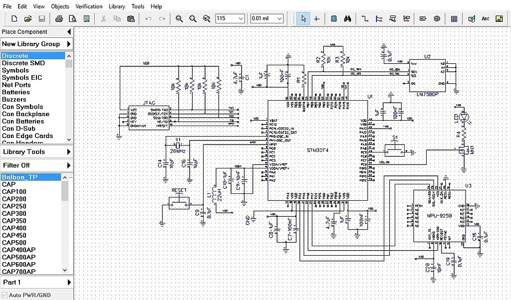


 Because there are only two valid Boolean values for representing either a logic “1” or a logic “0”, makes the system of using Binary Numbers ideal for use in digital or electronic circuits and systems.
 This is an analogue circuit. The output from the potentiometer varies as the wiper terminal is rotated producing an infinite number of output voltage points between 0 volts and Vmax. The output voltage can vary either slowly or rapidly from one value to the next so there is no sudden or step change between two voltage levels thereby producing a continuously variable output voltage. Examples of analogue signals include temperature, pressure, liquid levels and light intensity.
 Then we can see that the major difference between an analogue signal or quantity and a digital quantity is that an “Analogue” quantity is continuously changing over time while a “Digital” quantity has discrete (step by step) values. “LOW” to “HIGH” or “HIGH” to “LOW”.

 Then, when using a +5 volt supply any voltage input between 2.0v and 5v is recognised as a logic “1” value and any voltage input of below 0.8v is recognised as a logic “0” value. While the output of a logic gate between 2.7v and 5v represents a logic “1” value and a voltage output below 0.4v represents a logic “0” value. This is called “positive logic” and is used in these digital logic tutorials.

Tidak ada komentar:
Posting Komentar