Contactors and Protection Relays
motor starter type :
discrete and process manufacturing
- Building - HVAC
- Commercial equipment
- Food and beverage processing
- Hoisting
- Marine
- Material handling
- Material working (wood, ceramic, stone, pvc, metal)
- Mining mineral and metal
- Oil and gas
- Packaging
- Textile
- Washing machines
- Water and waste water
application
- Compressor for refinery
- Compressor for regasification
- Conveyor
- Drilling rig
- Extruder
- Fan
- Mixer
- Other application
- Press
- Process crane
- Progressive cavity pump
- Pump
- Rod pump
- Screw pump
- Separator
- Shredder
- Swapping pump
- Thruster
- Water injection pump
- Winch
Working of Contactors
A contactor is also a type of relay. Although they have been explained in earlier posts, their wide use and significance needs to be explained in detail.
Features of Contactors
- A contactor is a relay that is used for switching power.
- They usually handle very heavy loads like an electric motor, lighting and heating equipments and so on.
- Though their output is used for switching very high loads, they are controlled by a circuit with very less power.
- According to the loads they handle, they vary in sizes from a small device to as huge as a yard.
- Though they are used for switching purposes, they do not interrupt a short-circuit current like a circuit breaker.
- They have ratings ranging from a breaking current of a few amperes and 24 DC volts to thousands of amperes with many kilo volts.
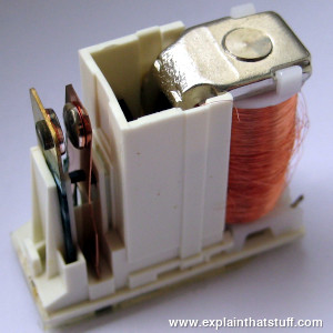
Contactor – Design and Construction
Like a relay, a contactor also has
- Contact
- Spring
- Electromagnet
The contact part of the contactor includes the power contacts as well as the auxiliary contacts. The power contacts gains the power for the contactor and the auxiliary contacts is used to bring a loop with the rest of the rest of the devices it is attached to. These contacts are connected to the contact springs.
The contacts are controlled by the electromagnet. These electromagnets give the initial force to the contacts and make them closed. Both these contacts and electromagnet are enclosed in a frame which is usually made of insulating materials. The usually used insulating materials are Nylon 6, thermosetting plastics and so on. They are useful, as they completely insulate the contacts and help in preventing the touch of contacts. For high-end contactors, an open-frame contactor is commonly used. This will provide a greater protection from oil, dust, weather and also from explosion. The type of frame housing used may also differ according to the voltage rating used. The ones given above are restricted up to a certain voltage. If the contactors are used to manage volts higher than 1000 volts, inert gases and also vacuum is used as frame housing.
Contactors are also used in DC circuits. For their use in DC circuits, magnetic blowouts are also used. The use of blowout coils help in stretching and moving the electric arc. The electric arcs can be AC or DC. An AC arc will have can be easily extinguished as they have low current characteristics. DC arcs of the same current characteristics need more stretching need more current to be blown out. They ratings differ from about 500 Amperes to about 1500 Amperes.
In order to save power in a contactor when it is closed, an economizer circuit is also introduced. This circuit helps in reducing the coil current. There is difference in the amount of power that is required to close the contactor and that from keeping it closed. Greater power is required to close it. This circuit will also help it to stay cooler. Take a look at the diagram given below.

- contactor relay
Working of Contactor
As contactors are used for high-current load applications they are designed to control and reduce the arc produced when the heavy motor currents are interrupted. Other than the low current contacts, they are also setup with Normally Open contacts. These are devices which handle more than 20 Amperes current and over 100 Kilo Watts power.
The contactor has an AC/DC supply driven coil input. This will depend on the requirement. This coil will mostly be controlled by a lower voltage PLC. They can also be controlled by the motor voltage. The motor may have series of coils connected to either control the acceleration or even the resistance.
When current is passed through the contactor, the electromagnet starts to build up, producing a magnetic field. Thus the core of the contactor starts to wind up. This process helps in energizing the moving contact. Thus the moving and fixed contacts make a short circuit. Thus the current is passed through them to the next circuit. The armature coil brings in high current in the initial position. This reduces as soon as the metal core enters the coil. When the current is stopped, the coil gets de-energized and thus the contacts get open circuited.
Contactor Ratings
Ratings of a contactor are given according to the pole of the contactor. It also depends on factors like fault withstand current, coil voltage and so on. According to their rating, contactors are classified into the following.
- AC1 – Non-inductive rows
- AC2 – Contactors for starting of slip-ring motors
- AC3 – Starting of squirrel-cage motors and switching off only after the motor is up to speed.
- AC4 – Starting of squirrel-cage motors with inching and plugging duty.
- AC11 – Auxiliary control circuits
Contactor Apllications
- Lighting control
- Magnetic starter
Working of Relays
What is a relay?
We know that most of the high end industrial application devices have relays for their effective working. Relays are simple switches which are operated both electrically and mechanically. Relays consist of a n electromagnet and also a set of contacts. The switching mechanism is carried out with the help of the electromagnet. There are also other operating principles for its working. But they differ according to their applications. Most of the devices have the application of relays.
Why is a relay used?
The main operation of a relay comes in places where only a low-power signal can be used to control a circuit. It is also used in places where only one signal can be used to control a lot of circuits. The application of relays started during the invention of telephones. They played an important role in switching calls in telephone exchanges. They were also used in long distance telegraphy. They were used to switch the signal coming from one source to another destination. After the invention of computers they were also used to perform Boolean and other logical operations. The high end applications of relays require high power to be driven by electric motors and so on. Such relays are called contactors.
Relay Design
There are only four main parts in a relay. They are
- Electromagnet
- Movable Armature
- Switch point contacts
- Spring
The figures given below show the actual design of a simple relay.

- Relay Construction
It is an electro-magnetic relay with a wire coil, surrounded by an iron core. A path of very low reluctance for the magnetic flux is provided for the movable armature and also the switch point contacts. The movable armature is connected to the yoke which is mechanically connected to the switch point contacts. These parts are safely held with the help of a spring. The spring is used so as to produce an air gap in the circuit when the relay becomes de-energized.
How relay works?
The working of a relay can be better understood by explaining the following diagram given below.

- Relay Design
The diagram shows an inner section diagram of a relay. An iron core is surrounded by a control coil. As shown, the power source is given to the electromagnet through a control switch and through contacts to the load. When current starts flowing through the control coil, the electromagnet starts energizing and thus intensifies the magnetic field. Thus the upper contact arm starts to be attracted to the lower fixed arm and thus closes the contacts causing a short circuit for the power to the load. On the other hand, if the relay was already de-energized when the contacts were closed, then the contact move oppositely and make an open circuit.
As soon as the coil current is off, the movable armature will be returned by a force back to its initial position. This force will be almost equal to half the strength of the magnetic force. This force is mainly provided by two factors. They are the spring and also gravity.
Relays are mainly made for two basic operations. One is low voltage application and the other is high voltage. For low voltage applications, more preference will be given to reduce the noise of the whole circuit. For high voltage applications, they are mainly designed to reduce a phenomenon called arcing.
Relay Basics
The basics for all the relays are the same. Take a look at a 4 – pin relay shown below. There are two colours shown. The green colour represents the control circuit and the red colour represents the load circuit. A small control coil is connected onto the control circuit. A switch is connected to the load. This switch is controlled by the coil in the control circuit. Now let us take the different steps that occour in a relay.

- relay operation
- Energized Relay (ON)
As shown in the circuit, the current flowing through the coils represented by pins 1 and 3 causes a magnetic field to be aroused. This magnetic field causes the closing of the pins 2 and 4. Thus the switch plays an important role in the relay working. As it is a part of the load circuit, it is used to control an electrical circuit that is connected to it. Thus, when the relay in energized the current flow will be through the pins 2 and 4.
")
- Energized Relay (ON)
- De – Energized Relay (OFF)
As soon as the current flow stops through pins 1 and 3, the switch opens and thus the open circuit prevents the current flow through pins 2 and 4. Thus the relay becomes de-energized and thus in off position.
")
- De-Energized Relay (OFF)
In simple, when a voltage is applied to pin 1, the electromagnet activates, causing a magnetic field to be developed, which goes on to close the pins 2 and 4 causing a closed circuit. When there is no voltage on pin 1, there will be no electromagnetic force and thus no magnetic field. Thus the switches remain open.
Pole and Throw
Relays have the exact working of a switch. So, the same concept is also applied. A relay is said to switch one or more poles. Each pole has contacts that can be thrown in mainly three ways. They are
- Normally Open Contact (NO) – NO contact is also called a make contact. It closes the circuit when the relay is activated. It disconnects the circuit when the relay is inactive.
- Normally Closed Contact (NC) – NC contact is also known as break contact. This is opposite to the NO contact. When the relay is activated, the circuit disconnects. When the relay is deactivated, the circuit connects.
- Change-over (CO) / Double-throw (DT) Contacts – This type of contacts are used to control two types of circuits. They are used to control a NO contact and also a NC contact with a common terminal. According to their type they are called by the names break before make and make before break contacts.
Relays are also named with designations like
- Single Pole Single Throw (SPST) – This type of relay has a total of four terminals. Out of these two terminals can be connected or disconnected. The other two terminals are needed for the coil.
- Single Pole Double Throw (SPDT) – This type of a relay has a total of five terminals. Out f these two are the coil terminals. A common terminal is also included which connects to either of two others.
- Double Pole Single Throw (DPST) – This relay has a total of six terminals. These terminals are further divided into two pairs. Thus they can act as two SPST’s which are actuated by a single coil. Out of the six terminals two of them are coil terminals.
- Double Pole Double Throw (DPDT) – This is the biggest of all. It has mainly eight relay terminals. Out of these two rows are designed to be change over terminals. They are designed to act as two SPDT relays which are actuated by a single coil.
Relay Applications
- Relays are used to realize logic functions. They play a very important role in providing safety critical logic.
- Relays are used to provide time delay functions. They are used to time the delay open and delay close of contacts.
- Relays are used to control high voltage circuits with the help of low voltage signals. Similarly they are used to control high current circuits with the help of low current signals.
- They are also used as protective relays. By this function all the faults during transmission and reception can be detected and isolated.
Relay Selection
We must note some factors while selecting a particular relay. They are
- Protection – Different protections like contact protection and coil protection must be noted. Contact protection helps in reducing arcing in circuits using inductors. Coil protection helps in reducing surge voltage produced during switching.
- Look for a standard relay with all regulatory approvals.
- Switching time – Ask for high speed switching relays if you want one.
- Ratings – There are current as well as voltage ratings. The current ratings vary from a few amperes to about 3000 amperes. In case of voltage ratings, they vary from 300 Volt AC to 600 Volt AC. There are also high voltage relays of about 15,000 Volts.
- Type of contact used – Whether it is a NC or NO or closed contact.
- Select Make before Break or Break before Make contacts wisely.
- Isolation between coil circuit and contacts
How to test a relay
We shows to us how to test a relay. A relay will usually have a coil, pole terminal and a set of contacts. The set of contacts that are open when the relay is not energized are called normally open (N/O) contacts and the set of contacts that are closed when the relay is not energized are called normally closed (N/C) contacts. The following steps can be used to perform the testing of the relay using a multimeter.
- Keep the multimeter in the continuity check mode.
- Check for continuity between the N/C contacts and pole.
- Check for discontinuity between N/O contacts and the pole.
- Now energise the relay using the rated voltage. For example use a 9V battery for energising a 9V relay. The relay will engage with clicking sound.
- Now check for continuity between N/O contacts and pole.
- Also check for discontinuity between N/C contacts and pole.
- As a final test, measure the resistance of the relay coil using a multimeter and check whether it is matching to the value stated by the manufacturer.
Basic Relays
Before going on to a deeper classification of the relays there are some basic relay circuits that must be kept in our mind. They are
- Voltage Suppression Relays
As relays are used in industrial purposes very often, they are mostly controlled with the help of computers. But when relays are controlled with such devices, there will surely be the presence of semi-conductors like transistors. This will in turn cause the presence of voltage spikes. As a result, it is really necessary to introduce voltage suppression devices, otherwise they will clearly destroy the transistors.
This voltage suppression can be introduced in two ways. Either the computer provides the suppression or the relay provides the suppression. If the relay provides the suppression they are called voltage-suppression relays. In relays voltage suppression is provided with the help of resistors of high value and even diodes and capacitors. Out of these diodes and resistors are more commonly used. Whatever device is used, it will be clearly stated in the relay.
De-spiking Diode Relays
A diode in the reverse-biased position is connected in parallel with the relay coil. As there is no flow of current due to such a connection, an open circuit of the relay will cause the current to stop flowing through the coil. This will have effect on the magnetic field. The magnetic field will be decreased instantly. This will cause the rise of an opposite voltage with very high reverse polarity to be induced. This is mainly caused because of the magnetic lines of force that cut the armature coil due to the open circuit. Thus the opposite voltage rises until the diode reaches 0.7 volts. As soon as this cut-off voltage is achieved, the diode becomes forward-biased. This causes a closed circuit in the relay, causing the entire voltage to pass through the load. The current thus produced will be flowing through the circuit for a very long time. As soon as the voltage is completely drained, this current flow will also stop.
De-spiking Resistor Relays
A resistor is almost efficient as that of a diode. It can not only suppress the voltage spikes efficiently, but also allows the entire current to flow through it when the relay is in the on position. Thus the current flow through it will also be very high. To reduce this, the value of the resistance should be as high as 1 Kilo Ohm. But, as the value of the resistors increases the voltage spiking capability of the relay decreases.
Types Of Relays
Here is a detailed list of the different types of relays.
1. Latching Relay
Latching relays are also called impulse relays. They work in the bistable mode, and thus have two relaxing states. They are also called keep relays or stay relays because as soon as the current towards this relay is switched off, the relay continues the process that it was doing in the last state. This can be achieved only with a solenoid which is operating in a ratchet and cam mechanism. It can also be done by an over-centre spring mechanism or a permanent magnet mechanism in which, when the coil is kept in the relaxed point, the over-centre spring holds the armature and the contacts in the right spot. This can also be done with the help of a remanent core.
In the ratchet and cam method, power consumption occurs only for a particular time. Hence it is more advantageous than the others.
2. Reed Relay
These types of relays have been given more importance in the contacts. In order to protect them from atmospheric protection they are safely kept inside a vacuum or inert gas. Though these types of relays have a very low switching current and voltage ratings, they are famous for their switching speeds.
3. Polarized Relay
This type of relay has been given more importance on its sensitivity. These relays have been used since the in

Relay Switch Circuit
Relays are electromechanical devices that use an electromagnet to operate a pair of movable contacts from an open position to a closed position.The advantage of relays is that it takes a relatively small amount of power to operate the relay coil, but the relay itself can be used to control motors, heaters, lamps or AC circuits which themselves can draw a lot more electrical power.
The electro-mechanical relay is an output device (actuator) which come in a whole host of shapes, sizes and designs, and have many uses and applications in electronic circuits. But while electrical relays can be used to allow low power electronic or computer type circuits to switch relatively high currents or voltages both “ON” or “OFF”, some form of relay switch circuit is required to control it.
The design and types of relay switching circuits is huge, but many small electronic projects use transistors and MOSFETs as their main switching device as the transistor can provide fast DC switching (ON-OFF) control of the relay coil from a variety of input sources so here is a small collection of some of the more common ways of switching relays.
NPN Relay Switch Circuit
A typical relay switch circuit has the coil driven by a NPN transistor switch, TR1 as shown depending on the input voltage level. When the Base voltage of the transistor is zero (or negative), the transistor is cut-off and acts as an open switch. In this condition no Collector current flows and the relay coil is de-energised because being current devices, if no current flows into the Base, then no current will flow through the relay coil.If a large enough positive current is now driven into the Base to saturate the NPN transistor, the current flowing from Base to Emitter (B to E) controls the larger relay coil current flowing through the transistor from the Collector to Emitter.
For most bipolar switching transistors, the amount of relay coil current flowing into the Collector would be somewhere between 50 to 800 times that of the required Base current to drive the transistor into saturation. The current gain, or beta value ( β ) of the general purpose BC109 shown is typically about 290 at 2mA (Datasheet).
NPN Relay Switch Circuit

When the transistor switches “OFF”, the current flowing through the relay coil decreases and the magnetic field collapses. However the stored energy within the magnetic field has to go some where and a reverse voltage is developed across the coil as it tries to maintain the current in the relay coil. This action produces a high voltage spike across the relays coil that can damage the switching NPN transistor if allowed to build up.
So in order to prevent damage to the semiconductor transistor, a “flywheel diode”, also known as a freewheeling diode, is connected across the relay coil. This flywheel diode clamps the reverse voltage across the coil to about 0.7V dissipating the stored energy and protecting the switching transistor. Flywheel diodes are only applicable when the supply is a polarized DC voltage. An AC coil requires a different protection method, and for this an RC snubber circuit is used.
NPN Darlington Relay Switch Circuit
The previous NPN transistor relay switch circuit is ideal for switching small loads such as LED’s and miniature relays. But sometimes it is required to switch larger relay coils or currents beyond the range of a BC109 general purpose transistor and this can be achieved using Darlington Transistors.The sensitivity and current gain of a relay switch circuit can be greatly increased by using a Darlington pair of transistors in place of a single switching transistor. Darlington Transistor pairs can be made from two individually connected Bipolar Transistors as shown or available as one single device with standard: Base, Emitter and Collector connecting leads.
The two NPN transistors are connected as shown so that the Collector current of the first transistor, TR1 becomes the Base current of the second transistor TR2. The application of a positive base current to TR1 automatically turns “ON” the switching transistor, TR2.
NPN Darlington Relay Switch Circuit

Emitter Follower Relay Switch Circuit
As well as the standard Common Emitter configuration for a relay switch circuit, the relay coil can also be connected to the Emitter terminal of the transistor to form an Emitter Follower circuit. The input signal is connected directly to the Base, while the output is taken from the Emitter load as shown.Emitter Follower Relay Switch Circuit

Emitter Darlington Relay Switch Circuit
This is the Darlington transistor version of the previous Emitter Follower circuit. A very small positive Base current applied to TR1 causes a much greater Collector current to flow through TR2 due to the multiplication of the two Beta values.Emitter Darlington Relay Switch Circuit

PNP Relay Switch Circuit
As well as switching relay coils and other such loads with NPN Bipolar Transistors, we can also switch them using PNP Bipolar Transistors. The PNP relay switch circuit is no different to the NPN relay switching circuit in terms of its ability to control the relays coil. However, it does require different polarities of operating voltages. For example, the Collector-Emitter voltage, Vce , must be negative for the PNP type to cause current flow from the Emitter to the Collector.PNP Relay Switch Circuit

In other words, when Vin is HIGH the PNP transistor is switched “OFF” and so too is the relay coil. When Vin is LOW, the Base voltage is less than the Emitter voltage, (more negative) and the PNP transistor turns “ON”. The Base resistor value sets the Base current, which sets the Collector current that drives the relay coil.
PNP transistor switches can be used when the switching signal is the reverse for an NPN transistor, for example the output of a CMOS NAND gate or other such logic device. A CMOS logic output has the drive strength at logic 0 to sink sufficient current to turn the PNP transistor “ON”. Then current sinks can be turned into current sources by using PNP transistors and a power supply of opposite polarity.
PNP Collector Relay Switch Circuit
The operation of this circuit is the same as the previous relay switching circuit. In this relay switch circuit, the relay load has been connected to the PNP transistors Collector. The ON-OFF switching action of the transistor and coil occurs when Vin is LOW, transistor “ON” and when Vin is HIGH, transistor “OFF”.PNP Collector Relay Switch Circuit

So in an NPN transistor, a HIGH voltage with respect to the Emitter is applied to the Base, current flows from the Collector to the Emitter and the NPN transistor switches “ON”. For a PNP transistor, a LOW voltage with respect to the Emitter is applied to the Base, current flows from the Emitter to the Collector and the PNP transistor switches “ON”.
N-channel MOSFET Relay Switch Circuit
MOSFET relay switching operation is very similar to Bipolar Junction Transistor (BJT) switch operation seen above, and any of the previous circuits can be implemented using MOSFETs. However, there are some major differences in the operation of the MOSFET circuits with the main ones being that MOSFETs are voltage operated devices, and as the Gate is electrically isolated from the Drain-Source channel, they have very high input impedances so the Gate current for a MOSFET is zero, therefore a base resistor is unnecessary.MOSFETs conduct through a conductive channel with the channel initially being closed, transistor “OFF”. This channel gradually increasing in conductive width as the voltage applied to the Gate terminal is slowly increased. In other words, the transistor operates by enhancing the channel as the Gate voltage increases and for this reason the this type of MOSFET is called an Enhancement MOSFET, or E-MOSFET.
N-channel Enhancement MOSFETs (NMOS) are the most commonly used type of MOSFET as a positive voltage on the Gate terminal switches the MOSFET “ON” and zero or a negative voltage on the Gate switches it “OFF”, making ideal as MOSFET relay switch. Complementary P-channel Enhancement MOSFETs are also available which, like the PNP BJT work with opposite voltages.
N-channel MOSFET Relay Switch Circuit

Then the enhancement mode MOSFET operates as a normally open switch making it ideal for switching small loads such as relays. E-type MOSFETs have high “OFF” resistance but moderate “ON” resistance (OK for most applications), so when selecting one for a particular switching application, its RDS value needs to be taken into consideration.
P-channel MOSFET Relay Switch Circuit
The P-channel Enhancement MOSFET (PMOS) is constructed the same as for the N-channel Enhancement MOSFET except that it operates with negative Gate voltages only. In other words, A P-channel MOSFET operates in the same fashion but with opposite polarities as the Gate must be more negative than the Source to turn “ON” the transistor by being forward-biased as shown.P-channel MOSFET Relay Switch Circuit

When a LOW voltage level is applied to the Gate, the P-channel MOSFET will be turned “ON”. This will cause current to flow through the low resistance path of e-MOSFETs channel operating the relay coil. Both N-channel and P-channel e-MOSFETs make excellent low voltage relay switching circuits and can easily be interfaced to a wide variety of digital logic gates and micro-processor applications.
Logic Controlled Relay Switch Circuit
The N-channel, enhancement-type MOSFET is extremely useful as a transistor switch because in its “OFF” state (with zero Gate bias) its channel has a very high resistance blocking current flow. However, a relatively small positive voltage greater than the threshold voltage VT, on its high impedance Gate causes it to begin conducting current from its Drain terminal to its Source terminal.Unlike the Bipolar Junction Transistor which requires a Base current to turn it “ON”, the e-MOSFET only requires a voltage on the Gate as due to its insulated Gate construction, zero current flows into the Gate. Then this makes the e-MOSFET, either N-channel or P-channel ideal to be driven directly by typical TTL or CMOS logic gates as shown.
Logic Controlled Relay Switch Circuit

Micro-controller Relay Switch Circuit
As well as digital logic gates, we can also use the output pins and channels of micro-controllers, PIC’s and processors to control the outside world. The circuit below shows how to interface a relay using a MOSFET switch.Micro-controller Relay Switch Circuit

Relay Switching Circuit Summary
In this tutorial we have seen how we can use both Bipolar Junction Transistors, either NPN or PNP and Enhancement MOSFETs, either N-channel or P-channel as a transistor switching circuit.Sometimes when building Electronic or Micro-controller circuits we want to use a transistor switch to control a high-power device, such as motors, lamps, heating elements or AC circuits. Generally these devices require larger currents or higher voltages than a single power transistor can handle then we can use a relay switching circuit to do this.
Bipolar transistors (BJT’s) make very good and cheap relay switching circuits, but BJT’s are current operated devices as they convert a small Base current into a larger load current to energise the relay coil.
However, the MOSFET switch is ideal as an electrical switch as it takes virtually no Gate current to turn “ON”, converting a Gate voltage into a load current. Therefore, a MOSFET can be operated as a voltage-controlled switch.
In many applications bipolar transistors can be substituted with enhancement-type MOSFETs offering faster switching action, much higher input impedance, and probably less power dissipation. The combination of a very high Gate impedance, very low power consumption in its “OFF” state, and very fast switching capability makes the MOSFET suitable for many digital switching applications. Also with zero Gate current its switching action can not overload the output circuit of a digital gate or micro-controller.
However, because the gate of an E-MOSFET is insulated from the rest of the component, it is especially sensitive to static electricity which could destroy the thin oxide layer on the Gate. Then special care should be taken either when handling the component, or when it is in use and that any circuit using e-MOSFETs includes appropriate protection from static and voltage spikes.
Also for additional protection of either BJT’s or MOSFETs, always use a flywheel diode across and relay coil to safely dissipate the back emf generated by the transistors switching action.

Electrical Relay
Thus far we have seen a selection of Input devices that can be used to detect or “sense” a variety of physical variables and signals and are therefore called SensorsBut there are also a variety of electrical and electronic devices which are classed as Output devices used to control or operate some external physical process. These output devices are commonly called Actuators.
Actuators convert an electrical signal into a corresponding physical quantity such as movement, force, sound etc. An actuator is also classed as a transducer because it changes one type of physical quantity into another and is usually activated or operated by a low voltage command signal. Actuators can be classed as either binary or continuous devices based upon the number of stable states their output has.
For example, a relay is a binary actuator as it has two stable states, either energised and latched or de-energised and unlatched, while a motor is a continuous actuator because it can rotate through a full 360o motion. The most common types of actuators or output devices are Electrical Relays, Lights, Motors and Loudspeakers.
We saw previously that solenoids can be used to electrically open latches, doors, open or close valves, and in a variety of robotic and mechatronic applications, etc. However, if the solenoid plunger is used to operate one or more sets of electrical contacts, we have a device called a relay that is so useful it can be used in an infinite number of different ways and in this tutorial we will look at Electrical Relays.
Electrical Relays can also be divided into mechanical action relays called “Electromechanical Relays” and those which use semiconductor transistors, thyristors, triacs, etc, as their switching device called “Solid State Relays” or SSR’s.
The Electromechanical Relay
The term Relay generally refers to a device that provides an electrical connection between two or more points in response to the application of a control signal. The most common and widely used type of electrical relay is the electromechanical relay or EMR.
An Electrical Relay
Electrical Relays however, are basically electrically operated switches that come in many shapes, sizes and power ratings suitable for all types of applications. Relays can also have single or multiple contacts within a single package with the larger power relays used for mains voltage or high current switching applications being called “Contactors”.
In this tutorial about electrical relays we are just concerned with the fundamental operating principles of “light duty” electromechanical relays we can use in motor control or robotic circuits. Such relays are used in general electrical and electronic control or switching circuits either mounted directly onto PCB boards or connected free standing and in which the load currents are normally fractions of an ampere up to 20+ amperes. The relay circuit are common in Electronics applications.
As their name implies, electromechanical relays are electro-magnetic devices that convert a magnetic flux generated by the application of a low voltage electrical control signal either AC or DC across the relay terminals, into a pulling mechanical force which operates the electrical contacts within the relay. The most common form of electromechanical relay consist of an energizing coil called the “primary circuit” wound around a permeable iron core.
This iron core has both a fixed portion called the yoke, and a moveable spring loaded part called the armature, that completes the magnetic field circuit by closing the air gap between the fixed electrical coil and the moveable armature. The armature is hinged or pivoted allowing it to freely move within the generated magnetic field closing the electrical contacts that are attached to it. Connected between the yoke and armature is normally a spring (or springs) for the return stroke to “reset” the contacts back to their initial rest position when the relay coil is in the “de-energized” condition, i.e. turned “OFF”.
Electromechanical Relay Construction

In the normally closed position, the contacts are permanently closed when the field current is “OFF” as the switch contacts return to their normal position. These terms Normally Open, Normally Closed or Make and Break Contacts refer to the state of the electrical contacts when the relay coil is “de-energized”, i.e, no supply voltage connected to the relay coil. Contact elements may be of single or double make or break designs. An example of this arrangement is given below.

When the contacts are closed the contact resistance should be zero, a short circuit, but this is not always the case. All relay contacts have a certain amount of “contact resistance” when they are closed and this is called the “On-Resistance”, similar to FET’s.
With a new relay and contacts this ON-resistance will be very small, generally less than 0.2Ω’s because the tips are new and clean, but over time the tip resistance will increase.
For example. If the contacts are passing a load current of say 10A, then the voltage drop across the contacts using Ohms Law is 0.2 x 10 = 2 volts, which if the supply voltage is say 12 volts then the load voltage will be only 10 volts (12 – 2). As the contact tips begin to wear, and if they are not properly protected from high inductive or capacitive loads, they will start to show signs of arcing damage as the circuit current still wants to flow as the contacts begin to open when the relay coil is de-energized.
This arcing or sparking across the contacts will cause the contact resistance of the tips to increase further as the contact tips become damaged. If allowed to continue the contact tips may become so burnt and damaged to the point were they are physically closed but do not pass any or very little current.
If this arcing damage becomes to severe the contacts will eventually “weld” together producing a short circuit condition and possible damage to the circuit they are controlling. If now the contact resistance has increased due to arcing to say 1Ω’s the volt drop across the contacts for the same load current increases to 1 x 10 = 10 volts dc. This high voltage drop across the contacts may be unacceptable for the load circuit especially if operating at 12 or even 24 volts, then the faulty relay will have to be replaced.
To reduce the effects of contact arcing and high “On-resistances”, modern contact tips are made of, or coated with, a variety of silver based alloys to extend their life span as given in the following table.
Electrical Relay Contact Tip Materials
- Ag (fine silver)
- 1. Electrical and thermal conductivity are the highest of all the metals.
- 2. Exhibits low contact resistance, is inexpensive and widely used.
- 3. Contacts tarnish easily through sulphurisation influence.
- AgCu (silver copper)
- 1. Known as “Hard silver” contacts and have better wear resistance and less tendency to arc and weld, but slightly higher contact resistance.
- AgCdO (silver cadmium oxide)
- 1. Very little tendency to arc and weld, good wear resistance and arc extinguishing properties.
- AgW (silver tungsten)
- 1. Hardness and melting point are high, arc resistance is excellent.
- 2. Not a precious metal.
- 3. High contact pressure is required to reduce resistance.
- 4. Contact resistance is relatively high, and resistance to corrosion is poor.
- AgNi (silver nickel)
- 1. Equals the electrical conductivity of silver, excellent arc resistance.
- AgPd (silver palladium)
- 1. Low contact wear, greater hardness.
- 2. Expensive.
- Platinum, Gold and Silver Alloys
- 1. Excellent corrosion resistance, used mainly for low-current circuits.
Electrical Relay Snubber Circuit

Electrical Relay Contact Types.
As well as the standard descriptions of Normally Open, (NO) and Normally Closed, (NC) used to describe how the relays contacts are connected, relay contact arrangements can also be classed by their actions. Electrical relays can be made up of one or more individual switch contacts with each “contact” being referred to as a “pole”. Each one of these contacts or poles can be connected or “thrown” together by energizing the relays coil and this gives rise to the description of the contact types as being:- SPST – Single Pole Single Throw
- SPDT – Single Pole Double Throw
- DPST – Double Pole Single Throw
- DPDT – Double Pole Double Throw
“Single Pole Double Throw – (Break before Make)”, or SPDT – (B-M)
Examples of just some of the more common diagrams used for electrical relay contact types to identify relays in circuit or schematic diagrams is given below but there are many more possible configurations.Electrical Relay Contact Configurations

- Where:
- C is the Common terminal
- NO is the Normally Open contact
- NC is the Normally Closed contact
When both a make and a break set of contact elements are present at the same time so that the two contacts are electrically connected to produce a common point (identified by three connections), the set of contacts are referred to as “Form C contacts” or change-over contacts. If no electrical connection exists between the make and break contacts it is referred to as a double change-over contact.
One final point to remember about using electrical relays. It is not advisable at all to connect relay contacts in parallel to handle higher load currents. For example, never attempt to supply a 10A load with two relay contacts in parallel that have 5A contact ratings each, as the mechanically operated relay contacts never close or open at exactly the same instant of time. The result is that one of the contacts will always be overloaded even for a brief instant resulting in premature failure of the relay over time.
Also, while electrical relays can be used to allow low power electronic or computer type circuits to switch relatively high currents or voltages both “ON” or “OFF”. Never mix different load voltages through adjacent contacts within the same relay such as for example, high voltage AC (240v) and low voltage DC (12v), always use separate relays for safety.
One of the more important parts of any electrical relay is its coil. This converts electrical current into an electromagnetic flux which is used to mechanically operate the relays contacts. The main problem with relay coils is that they are “highly inductive loads” as they are made from coils of wire. Any coil of wire has an impedance value made up of resistance ( R ) and inductance ( L ) in series (LR Series Circuit).
As the current flows through the coil a self induced magnetic field is generated around it. When the current in the coil is turned “OFF”, a large back emf (electromotive force) voltage is produced as the magnetic flux collapses within the coil (transformer theory). This induced reverse voltage value may be very high in comparison to the switching voltage, and may damage any semiconductor device such as a transistor, FET or micro-controller used to operate the relay coil.

When the current flowing through the coil is switched “OFF”, an induced back emf is generated as the magnetic flux collapses in the coil.
This reverse voltage forward biases the diode which conducts and dissipates the stored energy preventing any damage to the semiconductor transistor.
When used in this type of application the diode is generally known as a Flywheel Diode, Free-wheeling Diode and even Fly-back Diode, but they all mean the same thing. Other types of inductive loads which require a flywheel diode for protection are solenoids, motors and inductive coils.
As well as using flywheel Diodes for protection of semiconductor components, other devices used for protection include RC Snubber Networks, Metal Oxide Varistors or MOV and Zener Diodes.
The Solid State Relay.
While the electromechanical relay (EMR) are inexpensive, easy to use and allow the switching of a load circuit controlled by a low power, electrically isolated input signal, one of the main disadvantages of an electromechanical relay is that it is a “mechanical device”, that is it has moving parts so their switching speed (response time) due to physically movement of the metal contacts using a magnetic field is slow.Over a period of time these moving parts will wear out and fail, or that the contact resistance through the constant arcing and erosion may make the relay unusable and shortens its life. Also, they are electrically noisy with the contacts suffering from contact bounce which may affect any electronic circuits to which they are connected.
To overcome these disadvantages of the electrical relay, another type of relay called a Solid State Relay or (SSR) for short was developed which is a solid state contactless, pure electronic relay.
The solid state relay being a purely electronic device has no moving parts within its design as the mechanical contacts have been replaced by power transistors, thyristors or triac’s. The electrical separation between the input control signal and the output load voltage is accomplished with the aid of an opto-coupler type Light Sensor.
The Solid State Relay provides a high degree of reliability, long life and reduced electromagnetic interference (EMI), (no arcing contacts or magnetic fields), together with a much faster almost instant response time, as compared to the conventional electromechanical relay.
Also the input control power requirements of the solid state relay are generally low enough to make them compatible with most IC logic families without the need for additional buffers, drivers or amplifiers. However, being a semiconductor device they must be mounted onto suitable heatsinks to prevent the output switching semiconductor device from over heating.
Solid State Relay

Like the electromechanical relays, a Resistor-Capacitor (RC) snubber network is generally required across the output terminals of the SSR to protect the semiconductor output switching device from noise and voltage transient spikes when used to switch highly inductive or capacitive loads. In most modern SSR’s this RC snubber network is built as standard into the relay itself reducing the need for additional external components.
Non-zero crossing detection switching (instant “ON”) type SSR’s are also available for phase controlled applications such as the dimming or fading of lights at concerts, shows, disco lighting etc, or for motor speed control type applications.
As the output switching device of a solid state relay is a semiconductor device (Transistor for DC switching applications, or a Triac/Thyristor combination for AC switching), the voltage drop across the output terminals of an SSR when “ON” is much higher than that of the electromechanical relay, typically 1.5 – 2.0 volts. If switching large currents for long periods of time an additional heat sink will be required.
Input/Output Interface Modules, (I/O Modules) are another type of solid state relay designed specifically to interface computers, micro-controller or PIC’s to “real world” loads and switches. There are four basic types of I/O modules available, AC or DC Input voltage to TTL or CMOS logic level output, and TTL or CMOS logic input to an AC or DC Output voltage with each module containing all the necessary circuitry to provide a complete interface and isolation within one small device. They are available as individual solid state modules or integrated into 4, 8 or 16 channel devices.
Modular Input/Output Interface System.

In this tutorial about Electrical Relays, we have looked at both the electromechanical relay and the solid state relay which can be used as an output device (actuator) to control a physical process. In the next tutorial we will continue our look at output devices called Actuators and especially one that converts a small electrical signal into a corresponding physical movement using electromagnetism. The output device is called a Solenoid.
What are relays?
A relay is an electromagnetic switch operated by a relatively small electric current that can turn on or off a much larger electric current. The heart of a relay is an electromagnet (a coil of wire that becomes a temporary magnet when electricity flows through it). You can think of a relay as a kind of electric lever: switch it on with a tiny current and it switches on ("leverages") another appliance using a much bigger current. Why is that useful? As the name suggests, many sensors are incredibly sensitive pieces of electronic equipment and produce only small electric currents. But often we need them to drive bigger pieces of apparatus that use bigger currents. Relays bridge the gap, making it possible for small currents to activate larger ones. That means relays can work either as switches (turning things on and off) or as amplifiers (converting small currents into larger ones).How relays work
Here are two simple animations illustrating how relays use one circuit to switch on a second circuit.
When power flows through the first circuit (1), it activates the electromagnet (brown), generating a magnetic field (blue) that attracts a contact (red) and activates the second circuit (2). When the power is switched off, a spring pulls the contact back up to its original position, switching the second circuit off again.
This is an example of a "normally open" (NO) relay: the contacts in the second circuit are not connected by default, and switch on only when a current flows through the magnet. Other relays are "normally closed" (NC; the contacts are connected so a current flows through them by default) and switch off only when the magnet is activated, pulling or pushing the contacts apart. Normally open relays are the most common.
Here's another animation showing how a relay links two circuits together. It's essentially the same thing drawn in a slightly different way. On the left side, there's an input circuit powered by a switch or a sensor of some kind. When this circuit is activated, it feeds current to an electromagnet that pulls a metal switch closed and activates the second, output circuit (on the right side). The relatively small current in the input circuit thus activates the larger current in the output circuit:
- The input circuit (black loop) is switched off and no current flows through it until something (either a sensor or a switch closing) turns it on. The output circuit (blue loop) is also switched off.
- When a small current flows in the input circuit, it activates the electromagnet (shown here as a red coil), which produces a magnetic field all around it.
- The energized electromagnet pulls the metal bar in the output circuit toward it, closing the switch and allowing a much bigger current to flow through the output circuit.
- The output circuit operates a high-current appliance such as a lamp or an electric motor.
Who invented relays?
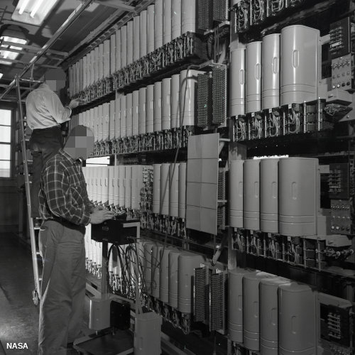
Photo: Relays were widely used for switching and routing calls in telephone exchanges such as this one, pictured in 1952. Photo by courtesy of NASA Glenn Research Center (NASA-GRC).
Relays were invented in 1835 by American electromagnetism pioneer Joseph Henry; in a demonstration at the College of New Jersey, Henry used a small electromagnet to switch a larger one on and off, and speculated that relays could be used to control electrical machines over very long distances. Henry applied this idea to another invention he was working on at the time, the electric telegraph (the forerunner of the telephone), which was successfully developed by William Cooke and Charles Wheatstone in England and (much more famously) by Samuel F. B. Morse in the United States. Relays were later used in telephone switching and early electronic computers and remained hugely popular until transistors came along in the late 1940s; according to Bancroft Gherardi, marking the 100th anniversary of Henry's work on electromagnetism, there were an estimated 70 million relays in operation in the United States alone by that time. Transistors are tiny electronic components that can do a similar job to relays, working as either amplifiers or switches. Although they switch faster, use far less electricity, take up a fraction of the space, and cost much less than relays, they generally work with only tiny currents so relays are still used in many applications. It was the development of transistors that spurred on the computer revolution from the mid-20th century onward. But without relays, there would have been no transistors, so relays—and pioneers like Joseph Henry—deserve some of the credit too!
How Relays Work
Relays are switches that open and close circuits electromechanically or electronically. Relays control one electrical circuit by opening and closing contacts in another circuit. As relay diagrams show, when a relay contact is normally open (NO), there is an open contact when the relay is not energized. When a relay contact is Normally Closed (NC), there is a closed contact when the relay is not energized. In either case, applying electrical current to the contacts will change their state.
Relays are generally used to switch smaller currents in a control circuit and do not usually control power consuming devices except for small motors and Solenoids that draw low amps. Nonetheless, relays can "control" larger voltages and amperes by having an amplifying effect because a small voltage applied to a relays coil can result in a large voltage being switched by the contacts.
Protective relays can prevent equipment damage by detecting electrical abnormalities, including overcurrent, undercurrent, overloads and reverse currents. In addition, relays are also widely used to switch starting coils, heating elements, pilot lights and audible alarms.
Relays are either electromechanical relays or solid-state relays. In electromechanical relays (EMR), contacts are opened or closed by a magnetic force. With solid-state relays (SSR), there are no contacts and switching is totally electronic. The decision to use electromechanical or solid state relays depends on an application's electrical requirements, cost constraints and life expectancy. Although solid-state relays have become very popular, electromechanical relays remain common. Many of the functions performed by heavy-duty equipment need the switching capabilities of electromechanical relays. Solid State Relays switche the current using non-moving electronic devices such as silicon controlled rectifiers.
These differences in the two types of relays result in advantages and disadvantages with each system. Because solid state relays do not have to either energize a coil or open contacts, less voltage is required to "turn" Solid State Relays on or off. Similarly, Solid State Relays turn on and turn off faster because there are no physical parts to move. Although the absence of contacts and moving parts means that Solid State Relays are not subject to arcing and do not wear out, contacts on Electromechanical Relays can be replaced, whereas entire Solid State Relays must be replaced when any part becomes defective. Because of the construction of Solid State Relays, there is residual electrical resistance and/or current leakage whether switches are open and closed. The small voltage drops that are created are not usually a problem; however, Electromechanical Relays provide a cleaner ON or OFF condition because of the relatively large distance between contacts, which acts as a form of insulation.
These differences in the two types of relays result in advantages and disadvantages with each system. Because solid state relays do not have to either energize a coil or open contacts, less voltage is required to "turn" Solid State Relays on or off. Similarly, Solid State Relays turn on and turn off faster because there are no physical parts to move. Although the absence of contacts and moving parts means that Solid State Relays are not subject to arcing and do not wear out, contacts on Electromechanical Relays can be replaced, whereas entire Solid State Relays must be replaced when any part becomes defective. Because of the construction of Solid State Relays, there is residual electrical resistance and/or current leakage whether switches are open and closed. The small voltage drops that are created are not usually a problem; however, Electromechanical Relays provide a cleaner ON or OFF condition because of the relatively large distance between contacts, which acts as a form of insulation.
Electromechanical Relays
Basic parts and functions of electromechanical relays include:
Relays involve two circuits: the energizing circuit and the contact circuit. The coil is on the energizing side; and the relays contacts are on the contact side. When a relays coil is energized, current flow through the coil creates a magnetic field. Whether in a DC unit where the polarity is fixed, or in an AC unit where the polarity changes 120 times per second, the basic function remains the same: the magnetic coil attracts a ferrous plate, which is part of the armature. One end of the armature is attached to the metal frame, which is formed so that the armature can pivot, while the other end opens and closes the contacts. Contacts come in a number of different configurations, depending on the number of Breaks, poles and Throws that make up the relay. For instance, relays might be described as Single-Pole, Single-Throw (SPST), or Double-Pole, Single-Throw (DPST). These terms will give an instant indication of the design and function of different types of relays.
- Frame: Heavy-duty frame that contains and supports the parts of the relay.
- Coil: Wire is wound around a metal core. The coil of wire causes an electromagnetic field.
- Armature: A relays moving part. The armature opens and closes the contacts. An attached spring returns the armature to its original position.
- Contacts: The conducting part of the switch that makes (closes) or breaks (opens) a circuit.
Relays involve two circuits: the energizing circuit and the contact circuit. The coil is on the energizing side; and the relays contacts are on the contact side. When a relays coil is energized, current flow through the coil creates a magnetic field. Whether in a DC unit where the polarity is fixed, or in an AC unit where the polarity changes 120 times per second, the basic function remains the same: the magnetic coil attracts a ferrous plate, which is part of the armature. One end of the armature is attached to the metal frame, which is formed so that the armature can pivot, while the other end opens and closes the contacts. Contacts come in a number of different configurations, depending on the number of Breaks, poles and Throws that make up the relay. For instance, relays might be described as Single-Pole, Single-Throw (SPST), or Double-Pole, Single-Throw (DPST). These terms will give an instant indication of the design and function of different types of relays.
- Break -This is the number of separate places or contacts that a switch uses to open or close a single electrical circuit. All contacts are either single break or double break. A single break (SB) contact breaks an electrical circuit in one place, while a double break (DB) contact breaks it in two places. Single break contacts are normally used when switching lower power devices such as indicating lights. Double break contacts are used when switching high-power devices such as solenoids.
- Pole -This is the number of completely isolated circuits that relays can pass through a switch. A single-pole contact (SP) can carry current through only one circuit at a time. A double-pole contact (DP) can carry current through two isolated circuits simultaneously. The maximum number of poles is 12, depending upon a relays design.
- Throw -This is the number of closed contact positions per pole that are available on a switch. A switch with a single throw contact can control only one circuit, while a double-throw contact can control two.
Types of Relyas: Electromechanical
- General Purpose Relays are electromechanical switches, usually operated by a magnetic coil. General purpose relays operate with AC or DC current, at common voltages such as 12V, 24V, 48V, 120V and 230V, and they can control currents ranging from 2A-30A. These relays are economical, easy to replace and allow a wide range of switch configuration.
- Machine Control Relays are also operated by a magnetic coil. They are heavy-duty relays used to control starters and other industrial components. Although they are more expensive than general purpose relays, they are generally more durable. The biggest advantage of machine control relays over general purpose relays is the expandable functionality of Machine Control Relays by the adding of accessories. A wide selection of accessories is available for machine control relays, including additional poles, convertible contacts, transient suppression of electrical noise, latching control and timing attachments.
- Reed Relays are a small, compact, fast operating switch design with one contact, which is NO. Reed Relays are hermetically sealed in a glass envelope, which makes the contacts unaffected by contaminants, fumes or humidity, allows reliable switching, and gives contacts a higher life expectancy. The ends of the contact, which are often plated with gold or another low resistance material to increase conductivity, are drawn together and closed by a magnet. Reed relays are capable of switching industrial components such as solenoids, contactors and starter motors. Reed relays consists of two reeds. When a magnetic force is applied, such as an electromagnet or coil, it sets up a magnetic field in which the end of the reeds assume opposite polarity. When the magnetic field is strong enough, the attracting force of the opposite poles overcomes the stiffness of the reeds and draws them together. When the magnetic force is removed, the reeds spring back to their original, open position. These relays work very quickly because of the short distance between the reeds.
Solid State Relays
Solid state relays consist of an input circuit, a control circuit and an output circuit. The Input Circuit is the portion of a relays frame to which the control component is connected. The input circuit performs the same function as the coil of electromechanical relays. The circuit is activated when a voltage higher than the relays specified Pickup Voltage is applied to the relays input. The input circuit is deactivated when the voltage applied is less than the specified minimum Dropout voltage of the relay. The voltage range of 3 VDC to 32 VDC, commonly used with most solid-state relays, makes it useful for most electronic circuits. The Control Circuit is the part of the relay that determines when the output component is energized or de-energized. The control circuit functions as the coupling between the input and output circuits. In electromechanical relays, the coil accomplishes this function. A relays Output Circuit is the portion of the relay that switches on the load and performs the same function as the mechanical contacts of electromechanical relays. Solid-state relays, however, normally have only one output contact. - Zero-Switching Relays - relays turns ON the load when the control (minimum operating) voltage is applied and the voltage of the load is close to zero. Zero-Switching relays turn OFF the load when the control voltage is removed and the current in the load is close to zero. Zero-Switching relays are the most widely used.
- Instant ON Relays - turns ON the load immediately when the pickup voltage is present. Instant ON Relays allow the load to be turned ON at any point in it's up and down wave.
- Peak Switching Relays - turns ON the load when the control voltage is present, and the voltage of the load is at its peak. Peak Switching relays turn OFF when the control voltage is removed and the current in the load is close to zero.
- Analog Switching Relays - has an infinite number of possible output voltages within the relays rated range. Analog switching relays have a built in synchronizing circuit that controls the amount of output voltage as a function of the input voltage. This allows a Ramp-Up function of time to be on the load. Analog Switching relays turn OFF when the control voltage is removed and current in the load is near zero.
A Relays Contact Life
A relays useful life depends upon its contacts. Once contacts burn out, the relays contacts or the entire relay has to be replaced. Mechanical Life is the number of operations (openings and closings) a contact can perform without electrical current. A relays mechanical life is relatively long, offering up to 1,000,000 operations. A relays Electrical life is the number of operations (openings and closings) the contacts can perform with electrical current at a given current rating. A relays Contact electrical life ratings range from 100,000 to 500,000 cycles. 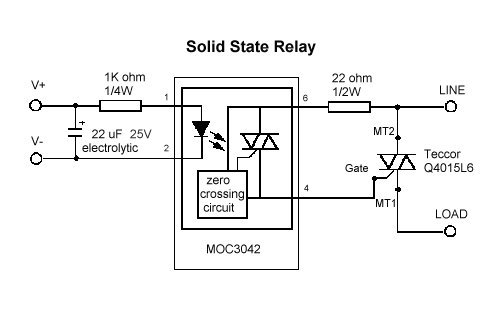
This diagram represents the basic circuit of Solid State Relays
How to Use Relays to Control Electronic Line-Voltage Circuits
In many electronics projects, you need to turn line-voltage powered circuits on and off using circuits that use low-voltage DC power supplies. For example, suppose you want to flash a 120 VAC flood lamp on and off at regular intervals. Relays to the rescue!
You could build a circuit to provide the necessary timing using a 555 timer integrated circuit (IC), but the 555 timer IC requires just a small DC power supply, in the range of 5 to 15 V. And the output current can’t exceed 200 mA, not nearly enough to light a flood lamp. That is where the relay come in.
A relay is an electromechanical device that uses an electromagnet to open or close a switch. The circuit that powers the electromagnet’s coil is completely separate from the circuit that is switched on or off by the relay’s switch, so it’s possible to use a relay whose coil requires just a few volts to turn a line voltage circuit on or off.
For this relay, the coil requires just 12 VDC to operate and pulls just 75 mA, well under the current limit that can be sourced by the 555 timer IC’s output pin. But the switch part of this relay can handle up to 10 A of current at 120 VAC, more than enough to illuminate a flood lamp.

The switch part of a relay is available in different configurations just like manual switches. The most common switch configuration is double pole, double throw (DPDT), which means that the relay actually controls two separate switches that operate together, and that each switch has both normally open and normally closed contacts.
Here is a schematic diagram for a simple circuit that uses a 9 VDC circuit with a handheld pushbutton to turn a 120 VAC lamp on and off. The relay in the circuit has a coil rated for 9 VDC and a switch rating of 10 A at 117 VAC. Thus, only 9 VDC passes through the handheld pushbutton. If the person holding the switch decides to take it apart, he or she won’t be exposed to dangerous voltage.

A more complicated circuit, in which a 555 timer IC controls a flood lamp via a relay is another option. Here, one end of the relay coil is connected to the 555 timer IC’s output pin (pin 3), and the other end is connected to ground. When the 555’s output switches on, the relay closes, and the flood lamp circuit is completed.

Note the diode that’s placed across the relay coil in this circuit. This diode is required to protect the 555 timer IC from any back-current that might be created within the relay’s coil when the coil is energized. Because of electromagnetic induction, relay coils are prone to this problem.
When the coil is energized, it creates a magnetic field that causes the relay’s switch contacts to move. However, this magnetic field has a subtle side effect. In the instant that the voltage on the coil goes from zero to the Vss supply voltage, the magnetic field surrounding the coil expands from nothing to its maximum strength.
During this expansion, the magnetic field is moving relative to the coil itself. Because of the principal of induction, this moving magnetic field induces a current in the coil itself, in the opposite direction as the current that is energizing the coil.
Depending on the circumstances, this back current can be powerful — powerful enough to overwhelm the output current coming from the 555 timer IC and possibly powerful enough to send current into the output pin, which can damage or destroy the 555 chip. D1 prevents this from happening by providing the equivalent of a short circuit across the coil for current flowing back toward the output pin.
Whenever you drive a relay from a circuit that has delicate components such as integrated circuits or transistors, you should always include a diode across the relay coil to prevent the relay from damaging your circuits.
How Batteries Work in Electronic Circuits
The easiest way to provide a voltage source for an electronic circuit is to include a battery. There are plenty of other ways to provide voltage, including AC adapters (which you can plug into the wall) and solar cells (which convert sunlight to voltage). However, batteries remain the most practical source of juice for most electronic circuits.
A battery is a device that converts chemical energy into electrical energy in the form of voltage, which in turn can cause current to flow.
A battery works by immersing two plates made of different metals into a special chemical solution called an electrolyte. The metals react with the electrolyte to produce a flow of charges that accumulate on the negative plate, called the anode. The positive plate, called the cathode, is sucked dry of charges. As a result, a voltage is formed between the two plates.
These plates are connected to external terminals to which you can connect a circuit to cause current to flow.

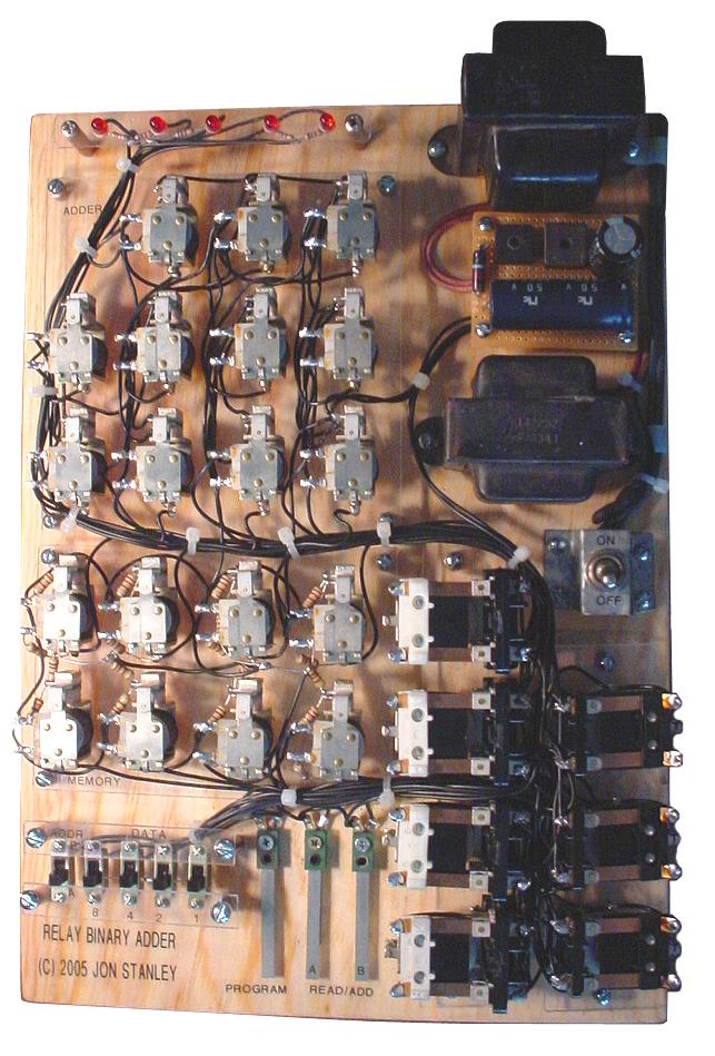
Basic Relay Computer
I obtained roughly 35 NOS relays for free from a friend who was cleaning out his garage. There was a forum discussion about vintage relay computers of the 30s to 50s, where various schematics of relay half-adders and full-adders were devised. I modeled my relay computer after the Homebuilt Computer in "How Things Work" by Neil Ardley. Basically the computer shown in the book has four data switches for 4-bit data and a switch to select the memory location A or B. The data is loaded into one of two memory locations of a 4508B 4-bit flip flop IC that serves as memory. The bits stored in memory can be read one at a time or summed through the 4008 4-bit binary adder. The binary output was decoded with a 4511 decoder to a 7-segment display.
Note that this basic relay computer is not a fully operational CPU, but actually a simple 4-bit relay adder with two 4-bit input storage/registers. This is as basic as a "computer" can get. Below are schematics of the half-adder and full-adder circuits that were devised by others at a forum.

 Relay Computer
Relay Computer Two
using the x86 instruction set for a relay computer to boot up Windows, which would’ve taken several hundred years on a relay computer running on a 50Hz clock. And so the inspiration began... (note: if you want to skip the hardware details of the computer, the pictures and videos are at the end of this page).
Seriously, the x86 instruction set is insanely large for a simple relay computer so I created my own instruction set. I looked at Harry Porter’s relay computer design for inspiration and ideas for the hardware. But first, the computer cannot exist without the actual relays. After searching several online electronics suppliers for relays, the lowest price I could find was at $1 per relay so a computer using 200+ relays can become rather expensive. So ebay was the next option and after patiently watching several auctions, a lot of 168 SPDT relays came up and I nabbed it for about $25. A few weeks later, another lot of 100 4PDT relays came up and I won it for about $14. Including shipping costs, the total cost for the 268 relays I purchased from ebay was about $60. So, 268 relays became my limit for the computer design. Obviously, I did not try to copy Harry Porter’s relay computer because it called for 400+ relays, but I borrowed many ideas from his design so I wouldn’t have to reinvent the wheel. During the weekends at school, the relay computer was designed with a limit of 268 relays (which eventually increased to 281 relays), a 8-bit data bus, a 16-bit address width, and a floating zero. Moreover, I created my own instruction set architecture (ISA) using only 5-bit instructions for simplicity. One might wonder "what the heck is a floating zero?" There is a significant difference between using a grounded zero compared to a floating zero in relay logic. The grounded zero means the zero is represented by a connection to the power supply ground. This can simplify certain logics such as the XOR, which would need only one relay. My first relay adder used the grounded zero. However, the grounded zero poses problems with other logics such as the memory registers due to the potential of shorting out the power supply. I circumvented this problem in my first relay adder by using resistors. A floating zero basically means there is no connection to the power supply ground, positive source, or anything, hence the name "floating" zero. This is hugely beneficial for avoiding shorts when the relays change states, especially in the registers.Before continuing to the details of the relay CPU hardware, the hardware is based on the instruction set architecture (ISA) chosen. My ISA is basically classified in four different categories: Branch, Data Movement, ALU Function, and Halt and the exact instructions and definitions may be viewed here: Relay Computer Two ISA.The relay CPU architecture is shown below:
The three registers and the ALU
The first step was to build the three CPU registers: A, B, and C. Below is a schematic of a single 8-bit relay register:
The Program Counter and Memory Address Registers
One might wonder, why a 16-bit address bus for a relay computer running on a clock rate that is over several thousand times slower than most computers in the seventies? 16-bits means 64KB of memory, and most personal computers in the seventies didn’t even have 8KB of memory! It would make more sense to limit the address width to 8 bits to match the data bus width, but that is only 256 bytes of memory. It might seem like plenty for one program, but I had planned on using a NV-SRAM (non-volatile static RAM) so I could store programs and not have to enter them in memory ever again so 256 bytes can be quite limiting. Expanding the address width to 10 or 11 bits would make better sense, but with absolute addressing it is a bit of a mismatch with a 8-bit data containing the first 8-bits of the absolute address and the next 8-bits of data with the first few bits for the upper n-bits of the absolute address. So I figured I’d go the whole nine yards and use twice the data bus width for the address width, so 16-bits for the width.The Program Counter, or PC for short, is a 16-bit register that stores the address of the CPU location in memory. This location is used to retrieve instructions or data from memory for execution. As the CPU executes the current instruction, the PC generally increments to the next location so the CPU can fetch the next instruction when it is done executing the current instruction. A 16-bit incrementer is used to increment the PC, using only 16 relays plus a few supporting relays. The following schematic is a half adder (a revised form of the full adder used in the ALU where the second relay is left out). An increment is achieved by feeding 1 and 0 in Cin and Cin’ respectively at the first half-adder. The output will be the incremented input.
The Finite State Machine
The Finite State Machine (FSM) controls all the aspects of the relay CPU like a conductor runs the orchestra. There are two parts to the FSM in all computers, the combinational logic and storage. In this relay computer, there is a sequencer (the storage component) that is basically a 12-state linear counter. The sequencer increments the state for every change in the clock; in other words, both a rising and falling edge of the clock triggers the sequencer. The relay logics decode the current state produced by the sequencer plus the instruction stored in the 5-bit instruction register to control all the subcomponents of the relay CPU, including the ALU and the PC unit.Below is the schematic of the 12-state sequencer used in my relay computer:
The RAM
The RAM I used is solid-state, so yes I admit this is not a 100% pure solid-state-free computer but the CPU is all relays. There are many reasons for using solid-state RAM. The obvious reason is because building RAM out of relays, core memory, or something is really difficult. Imagine 256 bytes of relay RAM, which is 2048 bits and not to mention the address decoder and everything else. Even if it was possible to use one relay per bit, 2048 bits for a mere 256 bytes of RAM is just simply expensive. Core memory was another consideration, but many geeks consider them collectibles and pay big bucks to obtain a small 16x16 matrix to put in a pretty little frame. Then there is the thought of buying a jar full of the ferrite doughnuts for a few bucks and make my own.So, I initially planned to use a Dallas DY1220 2KB non-volatile SRAM so I could store my programs in memory without ever having to reprogram the memory every time the computer was shut off. I planned on using a 32KB SRAM, but 2KB seemed satisfying and the CPU was designed for 64KB so at least it has expandability. I had another idea for simplifying the CPU by expanding the IR to 8-bits and use the last three bits as part of the address, but I had already built most of the CPU before I even thought about it, but the ideas will be explained later below.The challenge was to devise a level shifter to interface the RAM to the relay CPU. The RAM runs on 5 volts, so a logic 1 is 5V and logic 0 is 0V. The relay CPU uses 24V for a logic 1 and a floating connection for logic 0. The level shifter takes care of the differences like a money exchange for two currencies.I attempted to save parts so the level shifter was a bit tricky to design. The CPU-to-RAM converter was basically in parallel to the RAM-to-CPU converter. One or the other was simply active during a read or write, but there is the potential of closing a loop between the two converters, resulting in latched bits. After design number 5 or so, I eventually bought several 5-volt reed relays for the converter. However, the use of reed relays was a huge mistake because those relays are very sensitive to magnetic fields around them. In fact, I hooked up an ohmmeter to the reed relay contacts and energized the coil. There was continuity, but when I brought a small weak magnet about a half inch away from the relay, the switch opened! After a couple weeks of struggle to shield the reed relays with sheet metal and ensuring they switched properly, I gave up and bought REAL 24V relays from a local electronics store. The final design worked with these relays, as shown below:
The Power Supply
Of course nothing works without a power supply. Below is the schematic of a regulated 24VDC power supply using minimal parts and is capable of supplying up to 2.5A, which is roughly the peak current consumed by the relay computer depending on the clock speed and the contents of all the registers at a time. 24V at 2.5A maximum is roughly 60 watts peak, and on average, the relay CPU consumes about 40 watts.
RELAY COUNT
| COSTS
|
Lessons Learned
Below are a few tips so you don't repeat my mistakes if you decide to be crazy enough to build a relay computer.- Don't bother with a 16-bit address. In retrospect, I decided this was way more memory than necessary for a slow computer. Had I built this CPU a second time, I would opt for 8-bit addressing and keep the memory at 256 bytes. 9 to 11 bits is also reasonable and recall there are 3 unused bits in the instruction bytes that can be reused. There are several advantages with reducing the address length. First, less sequencer states would be necessary because there is less to transfer from memory to the Memory Address Registers. The PC and its incrementer would be reduced in size and save a lot of relays.
- Examine the instruction timing diagrams carefully and try not to cut corners when loading data into registers. The computer was not exactly 100% reliable over time due to relays starting to stick after operating for a while and causes unpredictable erroneous behavior.
- Some instructions are not as useful as I initially anticipated so there is room for improvement there.
- Make sure the clock that operates the sequencer is around 50% duty cycle. Any imbalance can cause switching issues because the sequencer advances on both "rising" and "falling" edges of the clock. I did not include a schematic diagram of the clock here because it can be built in any number of ways you prefer. I originally used a function generator that controlled 24V to generate the CLK signal, and then made a single relay oscillator that ran very slowly as the final solution.
The registers module is finished.

It contains 8 of 8 bit registers. One of them is instructions counter and another one - link register. Four of registers may be used for memory access.
It contains 8 of 8 bit registers. One of them is instructions counter and another one - link register. Four of registers may be used for memory access.
Clock generator
Started experimenting on clock generator. I designed a scheme which consists of 2 relays and RC circuits:

Then I bought two 100 Ohm resistors and two 1500 uF capacitors.

Soldered clock works with 2.66 seconds period:
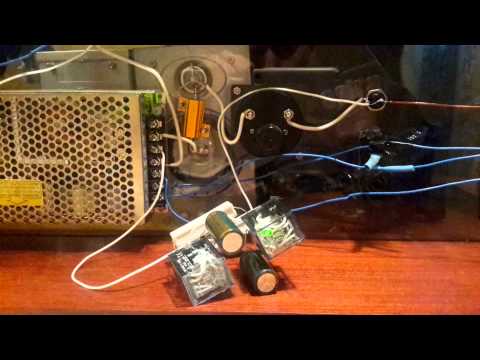
Time for energizing the capacitor and switch on the relay is about 0.2 sec (as I planned). And discharging the capacitor and switching off the relay takes 0.93-1.2 sec. Thus the left relay performs the charging-discharging cycle. It is switched on within ~1.2 sec and off within ~1.4 sec. This is almost perfect square wave.
I'll probably reduce the capacitors and make two speeds of execution (switched by "turbo" button).
Completely assembled ALU
After last post in the blog I made the following modifications of ALU:
- All the brass plates were engraved, drilled, and cut.
- Plates were installed on the main board.
- Bought and installed plastic backside to the cabinet.
- Screwed two hinges for hanging cabinet on the wall.

One more buggy relay
I almost finished wiring of the ALU module. After wiring arithmetic blocks' outputs to the result register I noticed, that some of the result bits do not receive values from the adder.
Here is the adder, which computed 0xff as a result:

Result register shows that two bits in 0xff are zeroes:

The root cause of the bug was in the buggy relay - two of the contacts of the relay in the adder enable circuit did not passed the current from inputs to outputs.
Fortunately, there were 3 spare switches in the relay for the CY in the enable circuit. I just duplicated the wires from the one of the enable relays to the CY one:

Relay computer "trainer"
The idea behind this project is to make a low relay count, single board computer similar to the single-board trainers of the early microcomputer era which can be mass produced for a reasonable price. CPU part of this computer consists of 83 relays. Other parts are based on ICs.

TIM relay computer
It consists of 152 relays and controlled by punch tape and DIP switches. This computer is the "smallest Turing complete relay computers in the world by relay count (with maybe the exception of the 'DUO Premium')".
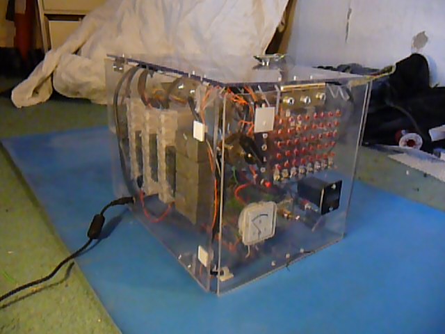
Relay testing board
After finding 3 failed relays within the subtractor module I decided to make a testing board for relays.
I checked about 30 relays using this board and all of them seem good. It seems strange because I found ~5 bad relays within set of ~50 already assembled.

relay computer
There is another documented relay computer - RC-3 built in Goodwill Computer Museum.

It is a clone of Harry Porter's relay computer. Here is the description of the computer from the site: "The RC-3 is an 8-bit computer with a 16-bit address bus that uses 418 electromechanical relays as logic elements. It has 421 lights and 134 switches on its front panel, and runs at the blinding speed of 6 Hz. It was designed and built by the founders of the Museum of Computer Culture during the 2010-2011 timeframe, when they were volunteers at Goodwill Computer Museum."
Tidak ada komentar:
Posting Komentar