
Block Diagram of an electronic safe

The cam mechanism would be such that turning the knob in the opposite direction is not going to engage the electronic safe .


Digital Combination Lock!

I've always wondered how did electronic locks work, so once i finished the basic digital electronics course I decided to build one myself. And I´ll help you to build your own!
You could connect it to anything from 1v to 400v(or maybe more that depends on the RELAY), DC or AC, so you could use it to control another circuit, or even to electrify a fence!! (please dont try that, really dangerous)… I connected a mini chrismas tree to the output (110v) cause I hadnt taken the holydays decoration off my lab, so it was around at the time i finished the proyect.
Step 1: How Does It Work?

First I thought in what was needed to be processed and how. So i drew this diagram as a map to guide me as i build each part of the proyect. Heres a summary of how it works.
- First we need a circuit to decode the 10 possible inputs (0-9) to its 4 output BCD (Binary Coded Decimal), and another output that tells us when any button is pressed.
- Then we need to build the circuit for our two 7-segments displays to work properly, with 4 inputs for a BCD number and of course 7 outs for our displays, ( I used the IC 74LS47)
- Then a circuit to save each pressed number and toggle between displays
- As well as an internal memory for our password
- And, the hearth of our lock, the comparator (its 8 bits ´cause there are 4 bits per digit in the display, meaning that if you want to do a 4 digit lock you will need two of this connected together.) This will tell us if the numbers in the displays are the same as the password saved in the internal memories.
- And finally a circuit to keep the OPEN or CLOSE signal for an undetermined time, and of course an output (thats whatever you want to control with your lock)
Step 2: Materials


Here´s all that you will need.
NOTE: I took most of the materials from an old VCR board, so they were "free" making this proyect really cheap. In total i spent about 13 dlls (most of the IC cost 76 cnts, exept for the D-ff (about 1.15) cause i had no IC, but you can keep them for future proyects, they are a great investment.
Components:
- Lots of Diodes (about 20) to make one way connections.
- One NPN transistor ( to feed the Relay Coil with enough current)
- One Relay (to control the connected device)
- One red LED ( to indicate when the system is LOCKED)
- 14 push buttons
- Lots of resistors (doesnt really matter the resistance, its just to set the IC pins to 1 or 0[+ or -])
- Two 7-segments Displays.
- A Lot of wire!!
Integrated Circuits:
- Two 7432(OR GATES) to build the DEC to BCD and the comparator
- Two 7486(XOR GATES) soul of the comparator.
- Two 7447 Display driver
- Four 74175(4 D-FF) each is a memory able to hold 4 bits.
- One 7476(2 JK-FF) for the display selector and to hold the OPEN CLOSE signal.
- One 7404(NOT GATE) invert the clock pulsefor the display selector. ( you could use an NPN transistor insted, cause you need only one gate ( the ic has 6).
Tools:
- 3 Protoboards (http://en.wikipedia.org/wiki/Breadboard)
- Pliers
- Exacto Knife
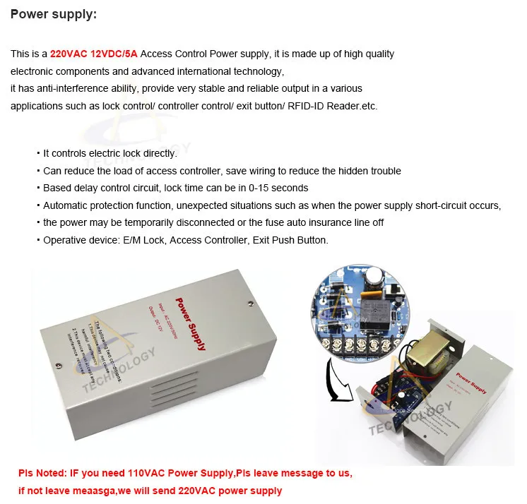
- 5V DC power supply(feeds circuits)
- 12V DC power supply(feeds the relay coil)
- 120V AC Power supply(feeds the device on the output)
NOTE:I used about 8 ft of wire, and advice about this, insted of buying expensive protoboard wire, you could Buy 3 ft of ethernet cable, the strip it, and you will have 8 or 9 wires, each with a diferent color and 3 ft long. (thats exactly what i do, since the normal protoboard wire is about 10 ft per dollar.
But for a buck you could 3.3 ft of ethernet cable, so you would end up with about 27-30 ft!
Step 3: Dec to BCD


The first step is building the input system, so you can comunicate with your lock.
I´ve designed the following circuit in order to achive two main goals.
- Turn any of the 10 numbers from (0-9) to its BCD (binary) counterpart.(Actually, there is an IC for this purpose, but it wasnt in stock when i went to my local electronic shop., so if you get it you will save yourself a lot of time and trouble, but I think is more fun this way )
- Being able to detect whenever a button is pressed.
To solve the first problem, we should take a look at this truth table to know which output (ABCD) will be high (1) when we press each button.
D C B A] X
0 0 0 0] 0
0 0 0 1] 1
0 0 1 0] 2
0 0 1 1] 3
0 1 0 0] 4
0 1 0 1] 5
0 1 1 0] 6
0 1 1 1] 7
1 0 0 0] 8
1 0 0 1] 9
Now heres where something I love about Digitals comes to a use…
There are many ways of doing one thing…. Its just like maths, you can get to 3 adding 1+2, or substracting 4-1, or 3^1….
In other words, you could build lots of diferents circuits to achive the same goal, this is something that makes our current task easier.
I designed this circuit cause I thought it used few ICs, but you could design your own!
Now, I know some maybe scratching their heads trying to figure out why did I used so many diodes, well here is the answer…
Diodes work like a one way connection, so in a pair connected as in my circuit, if there´s (1) voltage on its "positive side" it will conduce current, so we will have voltage in the other side aswell, but if there is a negative , or inexistent voltage (0) it will behave as an open circuit. Lets check the behavior of these diodes, calling the first diode anode (+) "E", and the second diode anode "F" and the output will be their connected cathode"X".
E F] X
0 0] 0
0 1] 1
1 0] 1
1 1] 1
You can see we have the exact same behavior than an OR GATE, and then,Why not using just diodes, that way you will save even more Integrated Circuits, and money?...Well the answer is simple, and you should really take it in consideration, the VOLTAGE DROPPED across EACH DIODE. It´s normally about 0.65V. Why is that? Because each diode needs at least 0.6 V across its anode and cathode to make its junction get close, so it can start conducting.I
In other words, for each diode you connect and its working at the same time, you will loose 0.65 V… that wouldnt be a big problem if we were only turning leds on, but we are working with TTL IC, that means that we need at least more than 2 V. And as we are starting with 5 v.. That means that conecting 5 diodes will cause a failure in our circuit ( the integrated circuit wouldnt be able to distinguish between 0v and less than 2v…)
That´s why I never used more than 2 diodes in each input…
NOTE: You must connect a resistor connected to GND in each OR Gate input…
To solve the second problem I just added a diode to each ABCD, and 0, and connected them together, so whenever any of those is 1, you will have a 1 on "Press"(P).
Step 4: Displays


These step is one of the easiest, we just need to decode the ABCD inputs to drive the seven segment display…And luckly there´s already an integrated circuit that will save us all the logic, time and space.
If you are using a Common Anode display then you will need a 7447.
If you are using a Common Cathode display then you will need a 7448.
The wiring is the same, so either way you could use my schematic.
The inputs ABCD for each IC come from each memory´s output (we will review the memories in the next step)
Step 5: Memory


This is were we change from combinational logic, to sequencial logic…
To make the 4 bits(ABCD) memory we just need a D- Flip Flop for each bit, and in the 74175 we have 4 of those.
Remember each number is represented in ABCD , so each 74175 can save one number.
The input of the first two memories (Data "D") comes from the DEC to BCD coder that we built on the first step.
Well we have the information that each one is going to hold, but, when are they going to save it?
Of course, one will save the first pressed number and the other the second pressed number…
So, how do we get this effect? Well with another kind of FF (flip flop) the JK, when both J and K inputs are high, it will change the state of the outputs to its complement (negation), in other words, we will have on "Q" 1, then 0 then 1 again, then 0 and so on. This Q and Q´ are the clock for the memories (what will tell´em when to save new data.)
The pulse that will determine when this change is made is the "P" that is high whenever you press any number, but to save the information on time, we will need the opposite, so heres where we use the NOT GATE.
In other words, once we push a button, the jk ff will change its output, turnin on the first memory, so that it will save the data, then we push again and the first memory recording state will be off, but the second memory will save the new data!
I added at this point a reset button that will turn both memories (ABCD) back to 0, and will return the display selector (jk ff) to the first memory.
Now… why did i said we need four 74175?
Well to save the password!! While its possible just to set the password with resistors to GND or Vcc, that will make your password static, and impossible to change if you get your lock done in a PCB.
So, with a memory, you can save the password, and change it as many times as you wish.
The inputs will be the outputs of our displays memory, so when a positive pulse reaches their clock, you will be coping whathever numbers are in the displays. (both, the memories and password memories will have the same information). Of course the "new password" pulse will only be avaliable if you already intruduced the correct password and opened the lock.
In all we will have a storage capacity of 2 Bytes or 16 bits!!
Step 6: Comparing


At this point we have a system thats capable of saving each number we press in one display then the other, and copying that information to the password memories… we are still lacking the essential, the Comparator… one circuit that will compare the two (ABCD) of the display memories with the two (ABCD) of the password memories.. Again, theres already an IC from the TTL family that does all the dirty job, but it wasnt in available in my local electronic shop.
So I built my own.
To understand how i did it lets look at the XOR truth table
A a] X
0 0] 0
0 1] 1
1 0] 1
1 1] 0
A a] X
0 0] 0
0 1] 1
1 0] 1
1 1] 0
Notice that whenever A and a have the same value, the output is low (0).
So if they are diferent we will have a 1 at the output.
Meaning that with one XOR Gate you can compare 2 bits one of the display memory and the other of the password memory. Based on that i built the following circuit, remember that you can build it your own way, cause there are many ways to get to the same answer here in digital electronics.
This circuit takes in the 8 bits of the display memories ( one bit per XOR, cause the other input should be used with the password memory) and the 8 bits of the password memories ( its a 1 Byte comparator).
And will deliver only one output.
if and only if the information on both display memories is the same as the information in the password memories, we will have a (0) low output. In other words, if the information on both sets of memories differ, even on 1 bit, the output will be high (1).
Step 7: Open/Close


Finally the last part, we are almost done! Soon enogh you will be able to lock any device, or electrify any fence,, ( Please dont!)
Now, we will take the last bit of information, and interrupt it with a push button, so if someone accidentaly writes the correct password, the lock wont open.( i called this button "enter", really clever, huh!,)
And after the enter button,will come the RS latch, one device that can turn Q´ to 1 if a there´s a 0 on its R input, and save it, and Q to 1 if theres a 0 in the S input.
I connected "Q" to a red led meaning lock, or that the controlled device is OFF.
And "Q´" to a transistor that will provide the relay with enough current to turn it, turning ON the countroled device.
"Q´" was connected to a push button, ( that i called new password button for obious reasons) so that when you push that button it you will close the circuit between Q´ and the clock input for the password memory. If Q´ is Low (system locked) nothing will change in the password memory when the button is pressed, but if it is High (system Open) clock will be activated and password memories will copy the information on the display memories.(changing the password).
And connected a resistor to GND and to a push button (lock button) and from there to the S input, so whenever you press it, you will lock the system.
Well, while i could have bought an RS flip flop just for this purpose, i still got one JK ff left from my 7476.
And, cause the inputs R and S are asincronous, we dont need to worry about the clock. So just wire things up as shown in the diagram ( as i did.)
Be Carefull when you connect the relay to AC, use enough isolating tape.. You dont want a short circuit when working with hundreds of volts!
After conecting everithing together…we are finally done!!! Please feel free to comment any question or suggest, if you notice any problem or mistake dont doubt in ponting it out. Im here to help.
Do We Need Flame Retardants in Electronics?
Disagreement burns over whether the chemicals in electronics are dangerous, or even provide any fire safety

The chemicals coating our electronics sometimes come with a disturbing profile. One common flame retardant used in the plastic casings of electronics, decabromodiphenyl ether, was voluntarily phased out by industry at the end of 2013 due to health and environmental concerns, including that it could potentially cause cancer or impact brain function. But some of the many alternatives that the U.S. Environmental Protection Agency anticipates will be used could degrade into tetrabromobisphenol A—itself a flame retardant that was labeled as a carcinogen by the National Institute of Environmental Health Sciences last year.
Flame retardants are chemically bound to the circuit boards of personal electronics during production—helping to keep any chemicals from seeping into the environment or possibly causing health repercussions for consumers (although it’s a different story for workers who process discarded electronics). The function of circuit boards is to transmit electrical current, so flame retardant proponents say fire protection is an obvious necessity.
Flame retardants are also embedded in the plastic shells that encase circuitry and electronics, with potentially more alarming health impacts. They are added to the plastics during a late stage of manufacturing without bonding to or reacting with the product material, making it easier for them to leach into the environment.
flashback safety electronic on Power dissipation and electronic components

An ever-present challenge in electronic circuit design is selecting suitable components that not only perform their intended task but also will survive under foreseeable operating conditions. A big part of that process is making sure that your components will stay within their safe operating limits in terms of current, voltage, and power. Of those three, the “power” portion is often the most difficult (for both newcomers and experts) because the safe operating area can depend so strongly on the particulars of the situation.
In what follows, we’ll introduce some of the basic concepts of power dissipation in electronic components, with an eye towards understanding how to select components for simple circuits with power limitations in mind.
— STARTING SIMPLE —
Let’s begin with one of the simplest circuits imaginable: A battery hooked up to a single resistor:
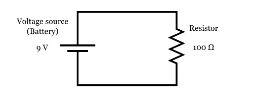
Here, we have a single 9 V battery, and a single 100 Ω (100 Ohm) resistor, hooked up with wires to form a complete circuit.
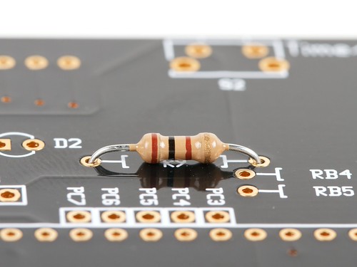
Easy enough, right? But now a question: If you want to actually build this circuit, how “big” of a 100 Ω resistor do you need to use to make sure that it doesn’t overheat? That is to say, can we just use a “regular” ¼ W resistor, like the one shown below, or do we need to go bigger?
To find out, we need to be able to calculate the amount of power that the resistor will dissipate.
Here’s the general rule for calculating power dissipation:
Power Rule: P = I × VIf a current I flows through through a given element in your circuit, losing voltage V in the process, then the power dissipated by that circuit element is the product of that current and voltage: P = I × V.
Aside:
How can current times voltage end up giving us a “power” measurement?
To understand this, we need to remember what current and voltage physically represent.
Electric current is the rate of flow of electric charge through the circuit, normally expressed in amperes, where 1 ampere = 1 coulomb per second. (The coulomb is the SI unit of electric charge.)
Voltage, or more formally, electric potential, is the potential energy per unit of electric charge —across the circuit element in question. In most cases, you can think of this as the the amount of energy that is “used up” in the element, per unit of charge that passes through. Electric potential is normally measured in volts, where 1 volt = 1 joule per coulomb. (The joule is the SI unit of energy.)
So, if we take a current times a voltage, that gives us the amount of energy that is “used up” in the element, per unit of charge, times the number of those units of charge passing through the element per second:
1 ampere × 1 volt =
1 ( coulomb / second ) × 1 ( joule / coulomb ) =
1 joule / second
The resulting quantity is in units of one joule per second: a rate of flow of energy, better known as power. The SI unit of power is the watt, where 1 watt = 1 joule per second.
Finally then, we have
1 ampere × 1 volt = 1 watt
Back to our circuit! To use the power rule (P = I × V), we need to know both the current through the resistor, and the voltage across the resistor.
First, we use Ohm’s law ( V = I × R ), to find the current through the resistor.
• The voltage across the resistor is V = 9 V.
• The resistance of the resistor is R = 100 Ω.
Therefore, the current through the resistor is:
I = V / R = 9 V / 100 Ω = 90 mA
• The current through the resistor is I = 90 mA.
• The voltage across the resistor is V = 9 V.
Therefore, the power dissipated in the resistor is:
P = I × V = 90 mA × 9 V = 0.81 W
So can you go ahead and use that 1/4 W resistor?
No, because it would likely fail from overheating.
The 100 Ω resistor in this circuit needs to be rated for at least 0.81 W. Generally, one picks the next larger available size, 1 W in this case.
A 1 W resistor typically comes in a much larger physical package, like the one shown here:
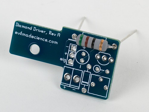
(A 1 W, 51 Ω resistor, for size comparison.)
Because a 1 W resistor is much larger physically, it should be able to handle dissipating a higher amount of power, with its higher surface area and wider leads. (It may still get very hot to the touch, but it should not get hot enough that it fails.)
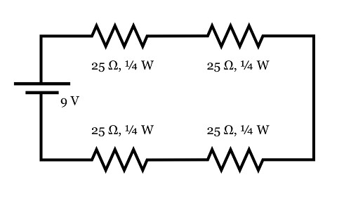
Here’s an alternate arrangement that works with four 25 Ω resistors in series (which still adds up to 100 Ω). In this case, the current through each resistor is still 90 mA. But, as there is only one quarter as much voltage across each resistor, there is only one quarter as much power dissipated in each resistor. For this arrangement, one only needs the four resistors to be rated for 1/4 W.
Aside: Working through that example.
Because the four resistors are in series, we can add their values together to get their total resistance, 100 Ω. Using Ohm’s law with that total resistance gives us the 90 mA current again. And again, since the resistors are in series, the same current (90 mA) must flow through each, back to the battery. The voltage across each 25 Ω resistor is then V = I × R, or 90 mA × 25 Ω = 2.25 V. (To double check that this is reasonable, note that the voltages across the four resistors sum up to 4 × 2.25 V = 9 V.)
The power across each individual 25 Ω resistor is P = I × V = 90 mA × 2.25 V ≈ 0.20 W, a safe level for use with a 1/4 W resistor. Intuitively, it also makes sense that if you divide up a 100 Ω resistor into four equal parts, each should dissipate one quarter of the total power.
— ON BEYOND RESISTORS —
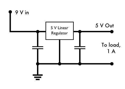
For our next example, let’s consider the following situation: Suppose that you have a circuit that takes input from a 9 V power supply, and has an onboard linear regulator to step the voltage down to 5 V, where everything actually runs. Your load, on the 5 V end, could be as high as 1 A.
What does the power look like in this situation?
The regulator essentially acts like a big variable resistor, that adjusts its resistance as needed to maintain a consistent 5 V output. When the output load is a full 1 A, the output power delivered by the regulator is 5 V × 1 A = 5 W, and the power input to the circuit by the 9 V power supply is 9 W. The voltage dropped across the regulator is 4 V, and at 1 A, that means that 4 W is dissipated by the linear regulator— also the difference between the power input and the power output.
In each part of this circuit, the power relationship is given by P = I × V. Two parts — the regulator and the load — are places where power is dissipated. And in the part of the circuit across the power supply, P = I × V describes the power input to the system— the voltage increases as the current travels across the power supply.
Additionally, it is worth noting that we have not said what kind of load is pulling that 1 A. Power is being consumed, but that does not necessarily mean that it is being converted into (just) heat energy— it could be powering a motor, or powering a set of battery chargers for example.
Aside:
While a linear voltage regulator setup like this is a very common setup for electronics, it’s worth pointing out that this is also an incredibly inefficient arrangement: 4/9 of the input power is simply burned off as heat, even when operated at lower currents.
While a linear voltage regulator setup like this is a very common setup for electronics, it’s worth pointing out that this is also an incredibly inefficient arrangement: 4/9 of the input power is simply burned off as heat, even when operated at lower currents.
— WHEN THERE ISN’T A SIMPLE “POWER” SPECIFICATION —
Next, a slightly more challenging part: making sure that your regulator can handle the power. While resistors are clearly labeled with their power capacity, linear regulators are not always. In our regulator example above, let’s further suppose that we’re using a L7805ABV regulator from ST (datasheet here).
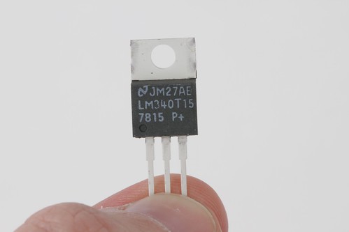
(Photo: A typical TO-220 case, the type typically used for medium-power linear regulators)
The L7805ABV is a 5 V linear regulator in a TO-220 package (similar to the one shown above), that is rated for 1.5 A output current and up to 35 V input voltage.
Naively, you might guess that you can hook this right up to 35 V input, and expect to get 1.5 A of output, meaning that the regulator would be radiating 30 V * 1.5 A = 45 W of power. But this is a tiny plastic package; it actually can’t handle that much power. If you look in the datasheet under the “Absolute maximum ratings” section, to try and find how much power it can handle, all that it says is “Internally limited” — which is anything but clear on its own.
It does turn out that there is an actual power rating, but it’s usually somewhat “hidden” within the datasheet. You can figure it out by looking at a couple of related specifications:
• TOP, Operating junction temperature range: -40 to 125 °C
• RthJA, Thermal resistance junction-ambient: 50 °C/W
• RthJC, Thermal resistance junction-case: 5 °C/W
The Operating junction temperature range, TOP, specifies how hot the “junction”– the active part of the regulator integrated circuit –can be allowed to get before it goes into thermal shutdown. (The thermal shutdown is the internal limit that makes the regulator power “Internally limited”.) For us, that’s a maximum of 125 °C.
The thermal resistance junction-ambient RthJA (Often written as ΘJA), tells us how hot the junction gets when (1) the regulator is dissipating a given amount of power and (2) the regulator is sitting in open air, at a given ambient temperature. Suppose that we need to design our regulator to only work under modest commercial conditions, that will not exceed 60 °C. If we need to keep the junction temperature under 125 °C, then the maximum temperature rise that we can allow is 65°C. If we have RthJA of 50 °C/W, then the maximum power dissipation that we can allow is 65/50 = 1.3 W, if we are to prevent the regulator from going into thermal shutdown. That’s well below the 4 W that we would expect with a 1 A load current. In fact, we can only tolerate 1.3 W / 4 V = 325 mA of average output current without sending the regulator into thermal shutdown.
This, however, is for the case of the TO-220 radiating to ambient air– almost a worst-case situation. If we can add a heat sink or otherwise cool the regulator, we can do much better.
The opposite end of the spectrum is given by the other thermal specification: the thermal resistance junction-case, RthJC. This specifies how much temperature difference you can expect between the junction and the outside of the TO-220 package: only 5 °C/W. This is the relevant number if you can quickly remove heat from the package, for example if you have a very good heat sink hooked up to the outside of the TO-220 package. With a big heat sink and perfect coupling to that heat sink, at 4 W, the junction temperature would rise only 20 °C above the temperature of your heat sink. This represents the absolute minimum heating that you can expect under ideal conditions.
Depending on the engineering requirements, you can start from this point to build a full power budget, to account for the thermal conductivity of every element of your system, from the regulator itself, to the thermal interface pad between it and the heat sink, to the thermal coupling of the heat sink to the ambient air. You can then verify the couplings and relative temperatures of each component with a spot-reading non-contact infrared thermometer. But often, it’s a better choice to re-evaluate the situation and see if there’s a better way to go about this.
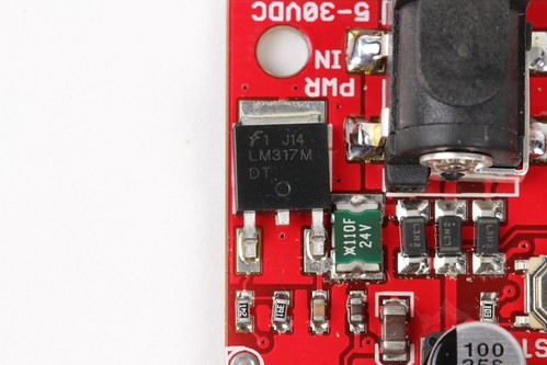
For the present situation, one might consider moving to a surface mount regulator that offers better power handling capability (by using the circuit board as a heat sink) or it may be worth looking into adding a power resistor (or zener diode) before the regulator to drop most of the voltage outside the regulator package, easing the load on it. Or better yet, seeing if there’s a way to build your circuit without the lossy linear regulator stage.
— AFTERWORD —
We have covered the basics of understanding power dissipation in a few simple, dc circuits.
The principles that we have gone over are quite general, and can be used to help understand power consumption in most types of passive elements and even most types of integrated circuits. There are real limitations, however, and one could spend a lifetime learning the nuances of power consumption, particularly at lower currents or high frequencies where small losses that we have neglected become important.
In ac circuits, many things behave very differently, but the power rule still holds in most circumstances: P(t) = I(t) × V(t) for time-varying current and voltage. And, not all regulators are all that lossy: Switching power supplies can convert (for example) 9 V dc to 5 V dc with 90% or higher efficiency– meaning that with good design, it may only take about 0.6 A at 9 V to produce 5 V at 1 A. But that’s a story for another time.
How Circuit Breakers Work
The circuit breaker is an absolutely essential device in the modern world, and one of the most important safety mechanisms in your home. Whenever electrical wiring in a building has too much current flowing through it, these simple machines cut the power until somebody can fix the problem. Without circuit breakers (or the alternative, fuses), household electricity would be impractical because of the potential for fires and other mayhem resulting from simple wiring problems and equipment failures.
In this article, we'll find out how circuit breakers and fuses monitor electrical current and how they cut off the power when current levels get too high. As we'll see, the circuit breaker is an incredibly simple solution to a potentially deadly problem.
To understand circuit breakers, it helps to know how household electricity works.
Electricity is defined by three major attributes:
- Voltage
- Current
- Resistance
Voltage, current and resistance are all interrelated -- you can't change one without changing another. Current is equal to voltage divided by resistance (commonly written as I = v / r). This makes intuitive sense: If you increase the pressure working on electric charge or decrease the resistance, more charge will flow.
Circuit Breaker: At Work in Your Home
The power distribution grid delivers electricity from a power plant to your house. Inside your house, the electric charge moves in a large circuit, which is composed of many smaller circuits. One end of the circuit, the hot wire, leads to the power plant. The other end, called the neutral wire, leads to ground. Because the hot wire connects to a high energy source, and the neutral wire connects to an electrically neutral source (the earth), there is a voltage across the circuit -- charge moves whenever the circuit is closed. The current is said to be alternating current, because it rapidly changes direction.
The power distribution grid delivers electricity at a consistent voltage (120 and 240 volts in the United States), but resistance (and therefore current) varies in a house. All of the different light bulbs and electrical appliances offer a certain amount of resistance, also described as the load. This resistance is what makes the appliance work. A light bulb, for example, has a filament inside that is very resistant to flowing charge. The charge has to work hard to move along, which heats up the filament, causing it to glow .
In building wiring, the hot wire and the neutral wire never touch directly. The charge running through the circuit always passes through an appliance, which acts as a resistor. In this way, the electrical resistance in appliances limits how much charge can flow through a circuit (with a constant voltage and a constant resistance, the current must also be constant). Appliances are designed to keep current at a relatively low level for safety purposes. Too much charge flowing through a circuit at a particular time would heat the appliance's wires and the building's wiring to unsafe levels, possibly causing a fire.
This keeps the electrical system running smoothly most of the time. But occasionally, something will connect the hot wire directly to the neutral wire or something else leading to ground. For example, a fan motor might overheat and melt, fusing the hot and neutral wires together. Or someone might drive a nail into the wall, accidentally puncturing one of the power lines. When the hot wire is connected directly to ground, there is minimal resistance in the circuit, so the voltage pushes a huge amount of charge through the wire. If this continues, the wires can overheat and start a fire.
 The simplest circuit protection device is the fuse. A fuse is just a thin wire, enclosed in a casing, that plugs into the circuit. When a circuit is closed, all charge flows through the fuse wire -- the fuse experiences the same current as any other point along the circuit. The fuse is designed to disintegrate when it heats up above a certain level -- if the current climbs too high, it burns up the wire. Destroying the fuse opens the circuit before the excess current can damage the building wiring.
The problem with fuses is they only work once. Every time you blow a fuse, you have to replace it with a new one. A circuit breaker does the same thing as a fuse -- it opens a circuit as soon as current climbs to unsafe levels -- but you can use it over and over again.
The basic circuit breaker consists of a simple switch, connected to either a bimetallic strip or an electromagnet. The diagram below shows a typical electromagnet design.
The hot wire in the circuit connects to the two ends of the switch. When the switch is flipped to the on position, electricity can flow from the bottom terminal, through the electromagnet, up to the moving contact, across to the stationary contact and out to the upper terminal.
The electricity magnetizes the electromagnet (See How Electromagnets Work to find out why). Increasing current boosts the electromagnet's magnetic force, and decreasing current lowers the magnetism. When the current jumps to unsafe levels, the electromagnet is strong enough to pull down a metal lever connected to the switch linkage. The entire linkage shifts, tilting the moving contact away from the stationary contact to break the circuit. The electricity shuts off.
All the wiring in a house runs through a central circuit breaker panel (or fuse box panel), usually in the basement or a closet. A typical central panel includes about a dozen circuit breaker switches leading to various circuits in the house. One circuit might include all of the outlets in the living room, and another might include all of the downstairs lighting. Larger appliances, such as a central air conditioning system or a refrigerator, are typically on their own circuit.

The power distribution grid delivers electricity at a consistent voltage (120 and 240 volts in the United States), but resistance (and therefore current) varies in a house. All of the different light bulbs and electrical appliances offer a certain amount of resistance, also described as the load. This resistance is what makes the appliance work. A light bulb, for example, has a filament inside that is very resistant to flowing charge. The charge has to work hard to move along, which heats up the filament, causing it to glow .
In building wiring, the hot wire and the neutral wire never touch directly. The charge running through the circuit always passes through an appliance, which acts as a resistor. In this way, the electrical resistance in appliances limits how much charge can flow through a circuit (with a constant voltage and a constant resistance, the current must also be constant). Appliances are designed to keep current at a relatively low level for safety purposes. Too much charge flowing through a circuit at a particular time would heat the appliance's wires and the building's wiring to unsafe levels, possibly causing a fire.
This keeps the electrical system running smoothly most of the time. But occasionally, something will connect the hot wire directly to the neutral wire or something else leading to ground. For example, a fan motor might overheat and melt, fusing the hot and neutral wires together. Or someone might drive a nail into the wall, accidentally puncturing one of the power lines. When the hot wire is connected directly to ground, there is minimal resistance in the circuit, so the voltage pushes a huge amount of charge through the wire. If this continues, the wires can overheat and start a fire.
Breaker Design: Basic
The problem with fuses is they only work once. Every time you blow a fuse, you have to replace it with a new one. A circuit breaker does the same thing as a fuse -- it opens a circuit as soon as current climbs to unsafe levels -- but you can use it over and over again.
The basic circuit breaker consists of a simple switch, connected to either a bimetallic strip or an electromagnet. The diagram below shows a typical electromagnet design.
The hot wire in the circuit connects to the two ends of the switch. When the switch is flipped to the on position, electricity can flow from the bottom terminal, through the electromagnet, up to the moving contact, across to the stationary contact and out to the upper terminal.
The electricity magnetizes the electromagnet (See How Electromagnets Work to find out why). Increasing current boosts the electromagnet's magnetic force, and decreasing current lowers the magnetism. When the current jumps to unsafe levels, the electromagnet is strong enough to pull down a metal lever connected to the switch linkage. The entire linkage shifts, tilting the moving contact away from the stationary contact to break the circuit. The electricity shuts off.
Click on the circuit breaker to release the switch.
A bimetallic strip design works on the same principle, except that instead of energizing an electromagnet, the high current bends a thin strip to move the linkage. Some circuit breakers use an explosive charge to throw the switch. When current rises above a certain level, it ignites explosive material, which drives a piston to open the switch.
Breaker Design: Advanced
More advanced circuit breakers use electronic components (semiconductor devices) to monitor current levels rather than simple electrical devices. These elements are a lot more precise, and they shut down the circuit more quickly, but they are also a lot more expensive. For this reason, most houses still use conventional electric circuit breakers.
One of the newer circuit breaker devices is the ground fault circuit interrupter, or GFCI. These sophisticated breakers are designed to protect people from electrical shock, rather than prevent damage to a building's wiring. The GFCI constantly monitors the current in a circuit's neutral wire and hot wire. When everything is working correctly, the current in both wires should be exactly the same. As soon as the hot wire connects directly to ground (if somebody accidentally touches the hot wire, for example), the current level surges in the hot wire, but not in the neutral wire. The GFCI breaks the circuit as soon as this happens, preventing electrocution. Since it doesn't have to wait for current to climb to unsafe levels, the GFCI reacts much more quickly than a conventional breaker.
One of the newer circuit breaker devices is the ground fault circuit interrupter, or GFCI. These sophisticated breakers are designed to protect people from electrical shock, rather than prevent damage to a building's wiring. The GFCI constantly monitors the current in a circuit's neutral wire and hot wire. When everything is working correctly, the current in both wires should be exactly the same. As soon as the hot wire connects directly to ground (if somebody accidentally touches the hot wire, for example), the current level surges in the hot wire, but not in the neutral wire. The GFCI breaks the circuit as soon as this happens, preventing electrocution. Since it doesn't have to wait for current to climb to unsafe levels, the GFCI reacts much more quickly than a conventional breaker.
All the wiring in a house runs through a central circuit breaker panel (or fuse box panel), usually in the basement or a closet. A typical central panel includes about a dozen circuit breaker switches leading to various circuits in the house. One circuit might include all of the outlets in the living room, and another might include all of the downstairs lighting. Larger appliances, such as a central air conditioning system or a refrigerator, are typically on their own circuit.
=================== ========SEATBACK==========================
Tidak ada komentar:
Posting Komentar