MARIA PREFER
( Moving Area Robotics In Allow Precision RE-liability Flexibility Efficiency of motion Robotic )
GUIDING e- STAR_C ( Stopwatch_Timer_Alarm __Clock )


Precision electronics :
The following terminology are often used in relation to the measurement uncertainty:
- Accuracy: The error between the real and measured value.
- Precision: The random spread of measured values around the average measured values.
- Resolution: The smallest to be distinguished magnitude from the measured value.
Measurement uncertainty
Measurement uncertainties can be divided into systematic and random measurement errors. The systematic errors are caused by abnormalities in gain and zero settings of the measuring equipment and tools. The random errors caused by noise and induced voltages and/or currents.Definition accuracy and precision
Often the concepts accuracy and precision are used interchangeably; they are regarded as synonymous. These two terms, however, have an entirely different meaning. The accuracy indicates how close the measured value is from its actual value, i.e. the deviation between the measured and actual values. Precision refers to the random spread of the measured values.
Histogram
The measured values can be plotted in a histogram as shown in Figure 1. The histogram shows how often a measured value occurs. The highest point of the histogram, this is the measured value that has been most frequently measured, indicates the mean value. This is indicated by the blue line in both graphs. The black line represents the real value of the parameter. The difference between the average measured value and real value is the accuracy. The width of the histogram indicates the spread of individual measurements. This distribution of measurements is called accuracy.Use the correct definition
Accuracy and precision thus have a different meaning. It is therefore quite possible that a measurement is very precise but not accurate. Or conversely, a very accurate measurement, but not precise. In general, a measurement is considered valid if both the measurement is precise as well accurate.Accuracy
Accuracy is an indication of the correctness of a measurement. Because at a single measurement the precision affects also the accuracy, an average of a series of measurements will be taken.The uncertainty of measuring instruments is usually given by two values: uncertainty of reading and uncertainty over the full scale. These two specifications together determine the total measurement uncertainty.
These values for the measurement uncertainty is specified in percent or in ppm (parts per million) relative to the current national standard. 1 % corresponds to 10000 ppm.
The specified uncertainty is quoted for specified temperature ranges and for certain time period after calibration. Please also note that at different ranges other uncertainties may apply.

Uncertainty relative to reading
An indication of a percentage deviation without further specification also refers to the reading. Tolerances of voltage dividers, the exact gain and absolute deviation of the readout and digitization cause this inaccuracy.A voltmeter which reads 70,00 V and has a "±5 % reading" specification, will have an uncertainty of 3,5 V (5 % of 70 V) above and below. The actual voltage will be between 66,5 en 73,5 volt.

Uncertainty relative to full scale
This type of inaccuracy is caused by offset errors and linearity errors of amplifiers. And with instruments that digitizes signals, by the non-linearity of the conversion and the uncertainty in AD converters. This specification refers to the full-scale range that is used.A voltmeter may have a specification "3 % full scale". If during a measurement the 100 V range is selected (= full scale), then the uncertainty is 3 % of 100 V = 3 V regardless of the voltage measured.
If the readout in this range 70 V, then the real voltage is between 67 and 73 volts.
Figure 3 makes clear that this type of tolerance is independent of the reading. Would a value of 0 V being read; in this case would the voltage in reality between -3 and +3 volts.
Full scale uncertainty in digits
Often give digital multimeters the full-scale uncertainty in digits instead of a percentage value.A digital multimeter with a 3½ digit display (range -1999 t / m 1999), the specification can read "+ 2 digits". This means that the uncertainty of the display is 2 units. For example: if a 20 volt range is chosen (± 19.99), than the full scale uncertainty is ±0.02 V. The display shows a value of 10.00 than the actual value shall be between 9.98 and 10.02 volts.

Calculation of measurement uncertainty
The specification of the tolerance of the reading and the full scale together determine the total measurement uncertainty of an instrument. In the following calculation example the same values are used as in the examples above:Accuracy: ±5 % reading (3 % full scale)
Range: 100 V, Reading: 70 V
The total measurement uncertainty is now calculated as follows:
 [equ. 1]
In this situation, a total uncertainty of 7.5 V up and down. The real value should be between 62.5 and 77.5 volts. Figure 4 shows this graphically.
The percentage uncertainty is the relationship between reading and uncertainty. In the given situation this is:
Digits
A digital multimeters can hold a specification of "±2.0 % rdg, + 4 digits. This means that 4 digits have to be added to the reading uncertainty of 2 %. As an example again a 3½ digit digital readout. This will read 5.00 V in while the 20 V range is selected. 2 % of the reading would mean an uncertainty of 0.1 V. Add to this the inaccuracy of the digits (= 0.04 V). The total uncertainty is therefore 0.14 V. The real value should be between 4.86 and 5.14 volts.Cumulative uncertainty
Often only the uncertainty of the measuring instrument is taken into account. But also must be looked after the additional measurement uncertainty of the measurement accessories if these are used. Here are a couple of examples:Increased uncertainty when using probe 1:10
When a 1:10 is used, not only the measurement uncertainty of the instrument must take into account. Also the input impedance of the used instrument and the resistance of the probe, who make together a voltage divider, shall influence the uncertainty.
(The uncertainty is also influenced by the resistance network that forms the internal resistance Ri. This is included in the specified tolerances.)

The tolerance of the input resistance of the oscilloscope can be found into the specifications. The tolerance of the series resistance Rp of the probe is not always given. However, the system uncertainty stated by the combination of the oscilloscope probe with a specified type oscilloscope will be known. If the probe is used with another type than the prescribed oscilloscope, the measurement uncertainty is undetermined. This must always be avoided.
Summation in quadrature
To get the resulting measurement uncertanty, all the relevant tolerances must be summed in quadrature. In the following example an oscilloscope has a tolerance of 1.5 % and a 1:10 probe is used with a system uncertainty of 2.5 %. These two specifications must be summation in quadrature to obtain total reading uncertainty:Measuring with a shunt resistor

The specified tolerance of the shunt resistor refers to the reading uncertainty. To find the total uncertainty, the tolerance of the shunt and the reading uncertainty of the measuring instrument are added in quadrature:
In this example, the total reading uncertainty is 2.5 %.
The resistance of the shunt is temperature dependent. The resistance value is specified for a given temperature. The temperature dependence is often expressed in ppm/°C.
As an example the calculating of the resistance value at ambient temperature (Tamb) of 30 °C. The shunt has a specification: R=100 Ω @ 22 °C (respectively Rnom & Tnom), and a temperature dependence of 20 ppm/°C.
 [equ. 5]
The current flowing through the shunt causes dissipation of energy in the shunt and this will result in rising of the temperature and therefore a change in resistance value. The change in resistance value due to the current flow is dependent on several factors. For very accurate measurements the shunt must be calibrated at a flow resistance and environmental conditions in which these will be used.
Precision
The term precision is used to express the random measurement error. The random nature of the deviations of the measured value is mostly of thermal origin. Because of the arbitrary nature of this noise it's not possible to give an absolute error. The precision gives only the probability that the measurement value is between given limits.
Gaussian distribution
Thermal noise has a Gaussian or normal distribution. This is described by the following equation: [equ. 6]
Here is μ the mean value and σ indicates the degree of dispersion and corresponds to the RMS value of the noise signal. The function provides a probability distribution curve as shown in Figure 8 where the mean value μ 2 is and the effective noise amplitude σ 1.
| Border | Chance |
| 0,5·σ | 38.3 % |
| 0,674·σ | 50.0 % |
| 1·σ | 68.3 % |
| 2·σ | 95.4 % |
| 3·σ | 99.7 % |
Probability table
Table 1 lists some chance values expressed at a certain limit. As seen, the probability that a measured value is within ±3·σ is 99.7 %.Improving precision
The precision of a measurement can be improved by oversampeling or filtering. The individual measurements are averaged out so that the noise quantity is greatly reduced. The spread of the measured values is hereby also reduced. With oversampling or filtering must be taken into account that this may reduce the bandwidth.Resolution
The resolution of a measurement system is the smallest yet to distinguish different in values. The specified resolution of an instrument has no relation to the accuracy of measurement.Digital measuring systems
A digital system converts an analog signal to a digital equivalent with an AD converter. The difference between two values, the resolution, is therefore always equal to one bit. Or in the case of a digital multimeter, this is 1 digit.It's also possible to express the resolution in other units than bits. As an example a digital oscilloscope which has an 8 bit AD converter. If the vertical sensitivity is set to 100 mV/div and the number of divisions is 8, the total range will be 800 mV. The 8 bits represent 28 = 256 different values. The resolution in volts is then 800 mV / 256 = 3125 mV.
Analog measuring systems
In the case of analog measuring instruments where the measured value is displayed in a mechanical way, such as a moving-coil meter, it's difficult to give an exact number for the resolution. Firstly, the resolution is limited by the mechanical hysteresis caused by friction of the bearings of the needle. On the other hand, resolution is determined by the observer, making this a subjective evaluation.Biorobotics

Kinesin uses protein domain dynamics on nanoscales to walk along a microtubule.
Biorobotics covers the fields of cybernetics, bionics and even genetic engineering as a collective study.Biorobotics may make robots that emulate or simulate living biological organisms mechanically or even chemically, or make biological organisms as manipulatable and functional as robots, or use biological organisms as components of robots. Biorobotics could use genetic engineering to create organisms designed by artificial means.
Bio-inspired robotics
Practical experimentation
A biological brain, grown from cultured neurons which were originally separated, has been developed as the neurological entity subsequently embodied within a robot body by Kevin Warwick and his team at University of Reading. The brain receives input from sensors on the robot body and the resultant output from the brain provides the robot's only motor signals. The biological brain is the only brain of the robot.
Biomechatronics
Biomechatronics is an applied interdisciplinary science that aims to integrate biology, mechanics, and electronics. It also encompasses the fields of robotics and neuroscience. Biomechatronic devices encompass a wide range of applications from the development of prosthetic limbs to engineering solutions concerning respiration, vision, and the cardiovascular system.
How it works
Biomechatronics mimics how the human body works. For example, four different steps must occur to be able to lift the foot to walk. First, impulses from the motor center of the brain are sent to the foot and leg muscles. Next the nerve cells in the feet send information, providing feedback to the brain, enabling it to adjust the muscle groups or amount of force required to walk across the ground. Different amounts of force are applied depending on the type of surface being walked across. The leg's muscle spindle nerve cells then sense and send the position of the floor back up to the brain. Finally, when the foot is raised to step, signals are sent to muscles in the leg and foot to set it down.Biosensors
Biosensors are used to detect what the user wants to do or their intentions and motions. In some devices the information can be relayed by the user's nervous system or muscle system. This information is related by the biosensor to a controller which can be located inside or outside the biomechatronic device. In addition biosensors receive information about the limb position and force from the limb and actuator. Biosensors come in a variety of forms. They can be wires which detect electrical activity, needle electrodes implanted in muscles, and electrode arrays with nerves growing through them.Mechanical sensors
The purpose of the mechanical sensors is to measure information about the biomechatronic device and relate that information to the biosensor or controller.Controller
The controller in a biomechatronic device relays the user's intentions to the actuators. It also interprets feedback information to the user that comes from the biosensors and mechanical sensors. The other function of the controller is to control the biomechatronic device's movements.Actuator
The actuator is an artificial muscle. Its job is to produce force and movement. Depending on whether the device is orthotic or prosthetic the actuator can be a motor that assists or replaces the user's original muscle.Research
Biomechatronics is a rapidly growing field but as of now there are very few labs which conduct research. The Shirley Ryan AbilityLab (formerly the Rehabilitation Institute of Chicago), University of California at Berkeley, MIT, Stanford University, and University of Twente in the Netherlands are the researching leaders in biomechatronics. Three main areas are emphasized in the current research.- Analyzing human motions, which are complex, to aid in the design of biomechatronic devices
- Studying how electronic devices can be interfaced with the nervous system.
- Testing the ways to use living muscle tissue as actuators for electronic devices
Analyzing motions
A great deal of analysis over human motion is needed because human movement is very complex. MIT and the University of Twente are both working to analyze these movements. They are doing this through a combination of computer models, camera systems, and electromyograms.Interfacing
Interfacing allows biomechatronics devices to connect with the muscle systems and nerves of the user in order send and receive information from the device. This is a technology that is not available in ordinary orthotics and prosthetics devices. Groups at the University of Twente and University of Malaya are making drastic steps in this department. Scientists there have developed a device which will help to treat paralysis and stroke victims who are unable to control their foot while walking. The researchers are also nearing a breakthrough which would allow a person with an amputated leg to control their prosthetic leg through their stump muscles.MIT research
Hugh Herr is the leading biomechatronic scientist at MIT. Herr and his group of researchers are developing a sieve integrated circuit electrode and prosthetic devices that are coming closer to mimicking real human movement. The two prosthetic devices currently in the making will control knee movement and the other will control the stiffness of an ankle joint.Robotic fish
As mentioned before Herr and his colleagues made a robotic fish that was propelled by living muscle tissue taken from frog legs. The robotic fish was a prototype of a biomechatronic device with a living actuator. The following characteristics were given to the fish.- A styrofoam float so the fish can float
- Electrical wires for connections
- A silicone tail that enables force while swimming
- Power provided by lithium batteries
- A microcontroller to control movement
- An infrared sensor enables the microcontroller to communicate with a handheld device
- Muscles stimulated by an electronic unit
Arts research
New media artists at UCSD are using biomechatronics in performance art pieces, such as Technesexual (more information, photos, video), a performance which uses biometric sensors to bridge the performers' real bodies to their Second Life avatars and Slapshock (more information, photos,video), in which medical TENS units are used to explore intersubjective symbiosis in intimate relationships.Growth
The demand for biomechatronic devices are at an all-time high and show no signs of slowing down. With increasing technological advancement in recent years, biomechatronic researchers have been able to construct prosthetic limbs that are capable of replicating the functionality of human appendages. Such devices include the "i-limb", developed by prosthetic company Touch Bionics, the first fully functioning prosthetic hand with articulating joints, as well as Herr's PowerFoot BiOM, the first prosthetic leg capable of simulating muscle and tendon processes within the human body. Biomechatronic research has also helped further research towards understanding human functions. Researchers from Carnegie Mellon and North Carolina State have created an exoskeleton that decreases the metabolic cost of walking by around 7 percent.Many biomechatronic researchers are closely collaborating with military organizations. The US Department of Veterans Affairs and the Department of Defense are giving funds to different labs to help soldiers and war veterans.
Despite the demand, however, biomechatronic technologies struggle within the healthcare market due to high costs and lack of implementation into insurance policies. Herr claims that Medicare and Medicaid specifically are important "market-breakers or market-makers for all these technologies," and that the technologies will not be available to everyone until the technologies get a breakthrough. Biomechatronic devices, although improved, also still face mechanical obstructions, suffering from inadequate battery power, consistent mechanical reliability, and neural connections between prosthetics and the human body
RE - liability electronics meaning
A practical definition of reliability is “the probability that a piece of equipment operating under specified conditions shall perform satisfactorily for a given period of time”. The reliability is a number between 0 and 1 respectively.
RE-liability ?
The ability of an apparatus, machine, or system to consistently perform
its intended or required function or mission, on demand and without
degradation or failure. ... Often expressed as mean time between failures (MTBF) or reliability coefficient. Also called quality over time.
Reliability prediction for electronic components
A prediction of reliability is an important element in the process of selecting equipment for use by telecommunications service providers and other buyers of electronic equipment, and it is essential during the design stage of engineering systems life cycle. Reliability is a measure of the frequency of equipment failures as a function of time. Reliability has a major impact on maintenance and repair costs and on the continuity of service.
Every product has a failure rate, λ which is the number of units failing per unit time. This failure rate changes throughout the life of the product. It is the manufacturer’s aim to ensure that product in the “infant mortality period” does not get to the customer. This leaves a product with a useful life period during which failures occur randomly i.e., λ is constant, and finally a wear-out period, usually beyond the products useful life, where λ is increasing.
Definition of reliability
A practical definition of reliability is “the probability that a piece of equipment operating under specified conditions shall perform satisfactorily for a given period of time”. The reliability is a number between 0 and 1 respectively.
MTBF and MTTF
MTBF (mean operating time between failures) applies to equipment that is going to be repaired and returned to service, MTTF (mean time to failure) applies to parts that will be thrown away on failing. During the ‘useful life period’ assuming a constant failure rate, MTBF is the inverse of the failure rate and the terms can be used interchangeably.Importance of reliability prediction
Reliability predictions:- Help assess the effect of product reliability on the maintenance activity and on the quantity of spare units required for acceptable field performance of any particular system. For example, predictions of the frequency of unit level maintenance actions can be obtained. Reliability prediction can be used to size spare populations.
- Provide necessary input to system-level reliability models. System-level reliability models can subsequently be used to predict, for example, frequency of system outages in steady-state, frequency of system outages during early life, expected downtime per year, and system availability.
- Provide necessary input to unit and system-level life cycle cost analyses. Life cycle cost studies determine the cost of a product over its entire life. Therefore, how often a unit will have to be replaced needs to be known. Inputs to this process include unit and system failure rates. This includes how often units and systems fail during the first year of operation as well as in later years.
- Assist in deciding which product to purchase from a list of competing products. As a result, it is essential that reliability predictions be based on a common procedure.
- Can be used to set factory test standards for products requiring a reliability test. Reliability predictions help determine how often the system should fail.
- Are needed as input to the analysis of complex systems such as switching systems and digital cross-connect systems. It is necessary to know how often different parts of the system are going to fail even for redundant components.
- Can be used in design trade-off studies. For example, a supplier could look at a design with many simple devices and compare it to a design with fewer devices that are newer but more complex. The unit with fewer devices is usually more reliable.
- Can be used to set achievable in-service performance standards against which to judge actual performance and stimulate action.
The RPP views electronic systems as hierarchical assemblies. Systems are constructed from units that, in turn, are constructed from devices. The methods presented predict reliability at these three hierarchical levels:
- Device: A basic component (or part)
- Unit: Any assembly of devices. This may include, but is not limited to, circuit packs, modules, plug-in units, racks, power supplies, and ancillary equipment. Unless otherwise dictated by maintenance considerations, a unit will usually be the lowest level of replaceable assemblies/devices. The RPP is aimed primarily at reliability prediction of units.
- Serial System: Any assembly of units for which the failure of any single unit will cause a failure of the system.
RE - liability engineering
Reliability engineering is a sub-discipline of systems engineering that emphasizes dependability in the lifecycle management of a product. Dependability, or reliability, describes the ability of a system or component to function under stated conditions for a specified period of time.[1] Reliability is closely related to availability, which is typically described as the ability of a component or system to function at a specified moment or interval of time.
Reliability is theoretically defined as the probability of success as the frequency of failures; or in terms of availability, as a probability derived from reliability, testability and maintainability. Testability, maintainability and maintenance are often defined as a part of "reliability engineering" in reliability programs. Reliability plays a key role in the cost-effectiveness of systems.

Reliability engineering deals with the estimation, prevention and management of high levels of "lifetime" engineering uncertainty and risks of failure. Although stochastic parameters define and affect reliability, reliability is not (solely) achieved by mathematics and statistics. One cannot really find a root cause (needed to effectively prevent failures) by only looking at statistics. "Nearly all teaching and literature on the subject emphasize these aspects, and ignore the reality that the ranges of uncertainty involved largely invalidate quantitative methods for prediction and measurement."For example, it is easy to represent "probability of failure" as a symbol or value in an equation, but it is almost impossible to predict its true magnitude in practice, which is massively multivariate, so having the equation for reliability does not begin to equal having an accurate predictive measurement of reliability.
Reliability engineering relates closely to safety engineering and to system safety, in that they use common methods for their analysis and may require input from each other. Reliability engineering focuses on costs of failure caused by system downtime, cost of spares, repair equipment, personnel, and cost of warranty claims. Safety engineering normally focuses more on preserving life and nature than on cost, and therefore deals only with particularly dangerous system-failure modes. High reliability (safety factor) levels also result from good engineering and from attention to detail, and almost never from only reactive failure management (using reliability accounting and statistics)
The objectives of reliability engineering, in decreasing order of priority, are:
- To apply engineering knowledge and specialist techniques to prevent or to reduce the likelihood or frequency of failures.
- To identify and correct the causes of failures that do occur despite the efforts to prevent them.
- To determine ways of coping with failures that do occur, if their causes have not been corrected.
- To apply methods for estimating the likely reliability of new designs, and for analysing reliability data.
Scope and techniques
Reliability engineering for "complex systems" requires a different, more elaborate systems approach than for non-complex systems. Reliability engineering may in that case involve:- System availability and mission readiness analysis and related reliability and maintenance requirement allocation
- Functional system failure analysis and derived requirements specification
- Inherent (system) design reliability analysis and derived requirements specification for both hardware and software design
- System diagnostics design
- Fault tolerant systems (e.g. by redundancy)
- Predictive and preventive maintenance (e.g. reliability-centered maintenance)
- Human factors / human interaction / human errors
- Manufacturing- and assembly-induced failures (effect on the detected "0-hour quality" and reliability)
- Maintenance-induced failures
- Transport-induced failures
- Storage-induced failures
- Use (load) studies, component stress analysis, and derived requirements specification
- Software (systematic) failures
- Failure / reliability testing (and derived requirements)
- Field failure monitoring and corrective actions
- Spare parts stocking (availability control)
- Technical documentation, caution and warning analysis
- Data and information acquisition/organisation (creation of a general reliability development hazard log and FRACAS system)
- Chaos engineering
- Tribology
- Stress (mechanics)
- Fracture mechanics / fatigue
- Thermal engineering
- Fluid mechanics / shock-loading engineering
- Electrical engineering
- Chemical engineering (e.g. corrosion)
- Material science
Definitions
Reliability may be defined in the following ways:- The idea that an item is fit for a purpose with respect to time
- The capacity of a designed, produced, or maintained item to perform as required over time
- The capacity of a population of designed, produced or maintained items to perform as required over specified time
- The resistance to failure of an item over time
- The probability of an item to perform a required function under stated conditions for a specified period of time
- The durability of an object
Basics of a reliability assessment
Many engineering techniques are used in reliability risk assessments, such as reliability hazard analysis, failure mode and effects analysis (FMEA), fault tree analysis (FTA), Reliability Centered Maintenance, (probabilistic) load and material stress and wear calculations, (probabilistic) fatigue and creep analysis, human error analysis, manufacturing defect analysis, reliability testing, etc. It is crucial that these analyses are done properly and with much attention to detail to be effective. Because of the large number of reliability techniques, their expense, and the varying degrees of reliability required for different situations, most projects develop a reliability program plan to specify the reliability tasks (statement of work (SoW) requirements) that will be performed for that specific system.Consistent with the creation of a safety cases, for example ARP4761, the goal of reliability assessments is to provide a robust set of qualitative and quantitative evidence that use of a component or system will not be associated with unacceptable risk. The basic steps to take[13] are to:
- Thoroughly identify relevant unreliability "hazards", e.g. potential conditions, events, human errors, failure modes, interactions, failure mechanisms and root causes, by specific analysis or tests.
- Assess the associated system risk, by specific analysis or testing.
- Propose mitigation, e.g. requirements, design changes, detection logic, maintenance, training, by which the risks may be lowered and controlled for at an acceptable level.
- Determine the best mitigation and get agreement on final, acceptable risk levels, possibly based on cost/benefit analysis.
In a de minimis definition, severity of failures includes the cost of spare parts, man-hours, logistics, damage (secondary failures), and downtime of machines which may cause production loss. A more complete definition of failure also can mean injury, dismemberment, and death of people within the system (witness mine accidents, industrial accidents, space shuttle failures) and the same to innocent bystanders (witness the citizenry of cities like Bhopal, Love Canal, Chernobyl, or Sendai, and other victims of the 2011 Tōhoku earthquake and tsunami)—in this case, reliability engineering becomes system safety. What is acceptable is determined by the managing authority or customers or the affected communities. Residual risk is the risk that is left over after all reliability activities have finished, and includes the unidentified risk—and is therefore not completely quantifiable.

Risk vs cost/complexity
Reliability and availability program plan
Implementing a reliability program is not simply a software purchase; it is not just a checklist of items that must be completed that will ensure one has reliable products and processes. A reliability program is a complex learning and knowledge-based system unique to one's products and processes. It is supported by leadership, built on the skills that one develops within a team, integrated into business processes and executed by following proven standard work practices.A reliability program plan is used to document exactly what "best practices" (tasks, methods, tools, analysis, and tests) are required for a particular (sub)system, as well as clarify customer requirements for reliability assessment. For large-scale complex systems, the reliability program plan should be a separate document. Resource determination for manpower and budgets for testing and other tasks is critical for a successful program. In general, the amount of work required for an effective program for complex systems is large.
A reliability program plan is essential for achieving high levels of reliability, testability, maintainability, and the resulting system availability, and is developed early during system development and refined over the system's life-cycle. It specifies not only what the reliability engineer does, but also the tasks performed by other stakeholders. A reliability program plan is approved by top program management, which is responsible for allocation of sufficient resources for its implementation.
A reliability program plan may also be used to evaluate and improve the availability of a system by the strategy of focusing on increasing testability & maintainability and not on reliability. Improving maintainability is generally easier than improving reliability. Maintainability estimates (repair rates) are also generally more accurate. However, because the uncertainties in the reliability estimates are in most cases very large, they are likely to dominate the availability calculation (prediction uncertainty problem), even when maintainability levels are very high. When reliability is not under control, more complicated issues may arise, like manpower (maintainers / customer service capability) shortages, spare part availability, logistic delays, lack of repair facilities, extensive retro-fit and complex configuration management costs, and others. The problem of unreliability may be increased also due to the "domino effect" of maintenance-induced failures after repairs. Focusing only on maintainability is therefore not enough. If failures are prevented, none of the other issues are of any importance, and therefore reliability is generally regarded as the most important part of availability. Reliability needs to be evaluated and improved related to both availability and the total cost of ownership (TCO) due to cost of spare parts, maintenance man-hours, transport costs, storage cost, part obsolete risks, etc. But, as GM and Toyota have belatedly discovered, TCO also includes the downstream liability costs when reliability calculations have not sufficiently or accurately addressed customers' personal bodily risks. Often a trade-off is needed between the two. There might be a maximum ratio between availability and cost of ownership. Testability of a system should also be addressed in the plan, as this is the link between reliability and maintainability. The maintenance strategy can influence the reliability of a system (e.g., by preventive and/or predictive maintenance), although it can never bring it above the inherent reliability.
The reliability plan should clearly provide a strategy for availability control. Whether only availability or also cost of ownership is more important depends on the use of the system. For example, a system that is a critical link in a production system—e.g., a big oil platform—is normally allowed to have a very high cost of ownership if that cost translates to even a minor increase in availability, as the unavailability of the platform results in a massive loss of revenue which can easily exceed the high cost of ownership. A proper reliability plan should always address RAMT analysis in its total context. RAMT stands for reliability, availability, maintainability/maintenance, and testability in the context of the customer's needs.
Reliability requirements
For any system, one of the first tasks of reliability engineering is to adequately specify the reliability and maintainability requirements allocated from the overall availability needs and, more importantly, derived from proper design failure analysis or preliminary prototype test results. Clear requirements (able to designed to) should constrain the designers from designing particular unreliable items / constructions / interfaces / systems. Setting only availability, reliability, testability, or maintainability targets (e.g., max. failure rates) is not appropriate. This is a broad misunderstanding about Reliability Requirements Engineering. Reliability requirements address the system itself, including test and assessment requirements, and associated tasks and documentation. Reliability requirements are included in the appropriate system or subsystem requirements specifications, test plans, and contract statements. Creation of proper lower-level requirements is critical. Provision of only quantitative minimum targets (e.g., MTBF values or failure rates) is not sufficient for different reasons. One reason is that a full validation (related to correctness and verifiability in time) of a quantitative reliability allocation (requirement spec) on lower levels for complex systems can (often) not be made as a consequence of (1) the fact that the requirements are probabilistic, (2) the extremely high level of uncertainties involved for showing compliance with all these probabilistic requirements, and because (3) reliability is a function of time, and accurate estimates of a (probabilistic) reliability number per item are available only very late in the project, sometimes even after many years of in-service use. Compare this problem with the continuous (re-)balancing of, for example, lower-level-system mass requirements in the development of an aircraft, which is already often a big undertaking. Notice that in this case, masses do only differ in terms of only some %, are not a function of time, the data is non-probabilistic and available already in CAD models. In case of reliability, the levels of unreliability (failure rates) may change with factors of decades (multiples of 10) as result of very minor deviations in design, process, or anything else. The information is often not available without huge uncertainties within the development phase. This makes this allocation problem almost impossible to do in a useful, practical, valid manner that does not result in massive over- or under-specification. A pragmatic approach is therefore needed—for example: the use of general levels / classes of quantitative requirements depending only on severity of failure effects. Also, the validation of results is a far more subjective task than for any other type of requirement. (Quantitative) reliability parameters—in terms of MTBF—are by far the most uncertain design parameters in any design.Furthermore, reliability design requirements should drive a (system or part) design to incorporate features that prevent failures from occurring, or limit consequences from failure in the first place. Not only would it aid in some predictions, this effort would keep from distracting the engineering effort into a kind of accounting work. A design requirement should be precise enough so that a designer can "design to" it and can also prove—through analysis or testing—that the requirement has been achieved, and, if possible, within some a stated confidence. Any type of reliability requirement should be detailed and could be derived from failure analysis (Finite-Element Stress and Fatigue analysis, Reliability Hazard Analysis, FTA, FMEA, Human Factor Analysis, Functional Hazard Analysis, etc.) or any type of reliability testing. Also, requirements are needed for verification tests (e.g., required overload stresses) and test time needed. To derive these requirements in an effective manner, a systems engineering-based risk assessment and mitigation logic should be used. Robust hazard log systems must be created that contain detailed information on why and how systems could or have failed. Requirements are to be derived and tracked in this way. These practical design requirements shall drive the design and not be used only for verification purposes. These requirements (often design constraints) are in this way derived from failure analysis or preliminary tests. Understanding of this difference compared to only purely quantitative (logistic) requirement specification (e.g., Failure Rate / MTBF target) is paramount in the development of successful (complex) systems.
The maintainability requirements address the costs of repairs as well as repair time. Testability (not to be confused with test requirements) requirements provide the link between reliability and maintainability and should address detectability of failure modes (on a particular system level), isolation levels, and the creation of diagnostics (procedures). As indicated above, reliability engineers should also address requirements for various reliability tasks and documentation during system development, testing, production, and operation. These requirements are generally specified in the contract statement of work and depend on how much leeway the customer wishes to provide to the contractor. Reliability tasks include various analyses, planning, and failure reporting. Task selection depends on the criticality of the system as well as cost. A safety-critical system may require a formal failure reporting and review process throughout development, whereas a non-critical system may rely on final test reports. The most common reliability program tasks are documented in reliability program standards, such as MIL-STD-785 and IEEE 1332. Failure reporting analysis and corrective action systems are a common approach for product/process reliability monitoring.
Reliability culture / human errors / human factors
In practice, most failures can be traced back to some type of human error, for example in:- Management decisions (e.g. in budgeting, timing, and required tasks)
- Systems Engineering: Use studies (load cases)
- Systems Engineering: Requirement analysis / setting
- Systems Engineering: Configuration control
- Assumptions
- Calculations / simulations / FEM analysis
- Design
- Design drawings
- Testing (e.g. incorrect load settings or failure measurement)
- Statistical analysis
- Manufacturing
- Quality control
- Maintenance
- Maintenance manuals
- Training
- Classifying and ordering of information
- Feedback of field information (e.g. incorrect or too vague)
- etc.
Furthermore, human errors in management; the organization of data and information; or the misuse or abuse of items, may also contribute to unreliability. This is the core reason why high levels of reliability for complex systems can only be achieved by following a robust systems engineering process with proper planning and execution of the validation and verification tasks. This also includes careful organization of data and information sharing and creating a "reliability culture", in the same way that having a "safety culture" is paramount in the development of safety critical systems.
Reliability prediction and improvement
Reliability prediction combines:- creation of a proper reliability model
- estimation (and justification) of input parameters for this model (e.g. failure rates for a particular failure mode or event and the mean time to repair the system for a particular failure)
- estimation of output reliability parameters at system or part level (i.e. system availability or frequency of a particular functional failure) The emphasis on quantification and target setting (e.g. MTBF) might imply there is a limit to achievable reliability, however, there is no inherent limit and development of higher reliability does not need to be more costly. In addition, they argue that prediction of reliability from historic data can be very misleading, with comparisons only valid for identical designs, products, manufacturing processes, and maintenance with identical operating loads and usage environments. Even minor changes in any of these could have major effects on reliability. Furthermore, the most unreliable and important items (i.e. the most interesting candidates for a reliability investigation) are most likely to be modified and re-engineered since historical data was gathered, making the standard (re-active or pro-active) statistical methods and processes used in e.g. medical or insurance industries less effective. Another surprising — but logical — argument is that to be able to accurately predict reliability by testing, the exact mechanisms of failure must be known and therefore — in most cases — could be prevented! Following the incorrect route of trying to quantify and solve a complex reliability engineering problem in terms of MTBF or probability using an-incorrect – for example, the re-active – approach is referred to by Barnard as "Playing the Numbers Game" and is regarded as bad practice.
To perform a proper quantitative reliability prediction for systems may be difficult and very expensive if done by testing. At the individual part-level, reliability results can often be obtained with comparatively high confidence, as testing of many sample parts might be possible using the available testing budget. However, unfortunately these tests may lack validity at a system-level due to assumptions made at part-level testing. These authors emphasized the importance of initial part- or system-level testing until failure, and to learn from such failures to improve the system or part. The general conclusion is drawn that an accurate and absolute prediction — by either field-data comparison or testing — of reliability is in most cases not possible. An exception might be failures due to wear-out problems such as fatigue failures. In the introduction of MIL-STD-785 it is written that reliability prediction should be used with great caution, if not used solely for comparison in trade-off studies.
Design for reliability
Design for Reliability (DfR) is a process that encompasses tools and procedures to ensure that a product meets its reliability requirements, under its use environment, for the duration of its lifetime. DfR is implemented in the design stage of a product to proactively improve product reliability.[20] DfR is often used as part of an overall Design for Excellence (DfX) strategy.Statistics-based approach (i.e. MTBF)
Reliability design begins with the development of a (system) model. Reliability and availability models use block diagrams and Fault Tree Analysis to provide a graphical means of evaluating the relationships between different parts of the system. These models may incorporate predictions based on failure rates taken from historical data. While the (input data) predictions are often not accurate in an absolute sense, they are valuable to assess relative differences in design alternatives. Maintainability parameters, for example Mean time to repair (MTTR), can also be used as inputs for such models.The most important fundamental initiating causes and failure mechanisms are to be identified and analyzed with engineering tools. A diverse set of practical guidance as to performance and reliability should be provided to designers so that they can generate low-stressed designs and products that protect, or are protected against, damage and excessive wear. Proper validation of input loads (requirements) may be needed, in addition to verification for reliability "performance" by testing.

A fault tree diagram
Another effective way to deal with reliability issues is to perform analysis that predicts degradation, enabling the prevention of unscheduled downtime events / failures. RCM (Reliability Centered Maintenance) programs can be used for this.
Physics-of-failure-based approach
For electronic assemblies, there has been an increasing shift towards a different approach called physics of failure. This technique relies on understanding the physical static and dynamic failure mechanisms. It accounts for variation in load, strength, and stress that lead to failure with a high level of detail, made possible with the use of modern finite element method (FEM) software programs that can handle complex geometries and mechanisms such as creep, stress relaxation, fatigue, and probabilistic design (Monte Carlo Methods/DOE). The material or component can be re-designed to reduce the probability of failure and to make it more robust against such variations. Another common design technique is component derating: i.e. selecting components whose specifications significantly exceed the expected stress levels, such as using heavier gauge electrical wire than might normally be specified for the expected electric current.Common tools and techniques
Many of the tasks, techniques, and analyses used in Reliability Engineering are specific to particular industries and applications, but can commonly include:- Physics of failure (PoF)
- Built-in self-test (BIT) (testability analysis)
- Failure mode and effects analysis (FMEA)
- Reliability hazard analysis
- Reliability block-diagram analysis
- Dynamic reliability block-diagram analysis
- Fault tree analysis
- Root cause analysis
- Statistical engineering, design of experiments – e.g. on simulations / FEM models or with testing
- Sneak circuit analysis
- Accelerated testing
- Reliability growth analysis (re-active reliability)
- Weibull analysis (for testing or mainly "re-active" reliability)
- Thermal analysis by finite element analysis (FEA) and / or measurement
- Thermal induced, shock and vibration fatigue analysis by FEA and / or measurement
- Electromagnetic analysis
- Avoidance of single point of failure (SPOF)
- Functional analysis and functional failure analysis (e.g., function FMEA, FHA or FFA)
- Predictive and preventive maintenance: reliability centered maintenance (RCM) analysis
- Testability analysis
- Failure diagnostics analysis (normally also incorporated in FMEA)
- Human error analysis
- Operational hazard analysis
- Preventative/Planned Maintenance Optimization (PMO)
- Manual screening
- Integrated logistics support
The importance of language
Reliability engineers, whether using quantitative or qualitative methods to describe a failure or hazard, rely on language to pinpoint the risks and enable issues to be solved. The language used must help create an orderly description of the function/item/system and its complex surrounding as it relates to the failure of these functions/items/systems. Systems engineering is very much about finding the correct words to describe the problem (and related risks), so that they can be readily solved via engineering solutions. Jack Ring said that a systems engineer's job is to "language the project." (Ring et al. 2000) For part/system failures, reliability engineers should concentrate more on the "why and how", rather that predicting "when". Understanding "why" a failure has occurred (e.g. due to over-stressed components or manufacturing issues) is far more likely to lead to improvement in the designs and processes used than quantifying "when" a failure is likely to occur (e.g. via determining MTBF). To do this, first the reliability hazards relating to the part/system need to be classified and ordered (based on some form of qualitative and quantitative logic if possible) to allow for more efficient assessment and eventual improvement. This is partly done in pure language and proposition logic, but also based on experience with similar items. This can for example be seen in descriptions of events in fault tree analysis, FMEA analysis, and hazard (tracking) logs. In this sense language and proper grammar (part of qualitative analysis) plays an important role in reliability engineering, just like it does in safety engineering or in-general within systems engineering.Correct use of language can also be key to identifying or reducing the risks of human error, which are often the root cause of many failures. This can include proper instructions in maintenance manuals, operation manuals, emergency procedures, and others to prevent systematic human errors that may result in system failures. These should be written by trained or experienced technical authors using so-called simplified English or Simplified Technical English, where words and structure are specifically chosen and created so as to reduce ambiguity or risk of confusion (e.g. an "replace the old part" could ambiguously refer to a swapping a worn-out part with a non worn-out part, or replacing a part with one using a more recent and hopefully improved design).
Reliability modeling
Reliability modeling is the process of predicting or understanding the reliability of a component or system prior to its implementation. Two types of analysis that are often used to model a complete system's availability behavior (including effects from logistics issues like spare part provisioning, transport and manpower) are Fault Tree Analysis and reliability block diagrams. At a component level, the same types of analyses can be used together with others. The input for the models can come from many sources including testing; prior operational experience; field data; as well as data handbooks from similar or related industries. Regardless of source, all model input data must be used with great caution, as predictions are only valid in cases where the same product was used in the same context. As such, predictions are often only used to help compare alternatives.
A reliability block diagram showing a "1oo3" (1 out of 3) redundant designed subsystem
- The physics of failure approach uses an understanding of physical failure mechanisms involved, such as mechanical crack propagation or chemical corrosion degradation or failure;
- The parts stress modeling approach is an empirical method for prediction based on counting the number and type of components of the system, and the stress they undergo during operation.
Reliability theory
Reliability is defined as the probability that a device will perform its intended function during a specified period of time under stated conditions. Mathematically, this may be expressed as,- ,


There are a few key elements of this definition:
- Reliability is predicated on "intended function:" Generally, this is taken to mean operation without failure. However, even if no individual part of the system fails, but the system as a whole does not do what was intended, then it is still charged against the system reliability. The system requirements specification is the criterion against which reliability is measured.
- Reliability applies to a specified period of time. In practical terms, this means that a system has a specified chance that it will operate without failure before time . Reliability engineering ensures that components and materials will meet the requirements during the specified time. Note that units other than time may sometimes be used (e.g. "a mission", "operation cycles").
- Reliability is restricted to operation under stated (or explicitly defined) conditions. This constraint is necessary because it is impossible to design a system for unlimited conditions. A Mars Rover will have different specified conditions than a family car. The operating environment must be addressed during design and testing. That same rover may be required to operate in varying conditions requiring additional scrutiny.
- Two notable references on reliability theory and its mathematical and statistical foundations are Barlow, R. E. and Proschan, F. (1982) and Samaniego, F. J. (2007).

Quantitative system reliability parameters—theory
Quantitative requirements are specified using reliability parameters. The most common reliability parameter is the mean time to failure (MTTF), which can also be specified as the failure rate (this is expressed as a frequency or conditional probability density function (PDF)) or the number of failures during a given period. These parameters may be useful for higher system levels and systems that are operated frequently (i.e. vehicles, machinery, and electronic equipment). Reliability increases as the MTTF increases. The MTTF is usually specified in hours, but can also be used with other units of measurement, such as miles or cycles. Using MTTF values on lower system levels can be very misleading, especially if they do not specify the associated Failures Modes and Mechanisms (The F in MTTF).In other cases, reliability is specified as the probability of mission success. For example, reliability of a scheduled aircraft flight can be specified as a dimensionless probability or a percentage, as often used in system safety engineering.
A special case of mission success is the single-shot device or system. These are devices or systems that remain relatively dormant and only operate once. Examples include automobile airbags, thermal batteries and missiles. Single-shot reliability is specified as a probability of one-time success or is subsumed into a related parameter. Single-shot missile reliability may be specified as a requirement for the probability of a hit. For such systems, the probability of failure on demand (PFD) is the reliability measure — this is actually an "unavailability" number. The PFD is derived from failure rate (a frequency of occurrence) and mission time for non-repairable systems.
For repairable systems, it is obtained from failure rate, mean-time-to-repair (MTTR), and test interval. This measure may not be unique for a given system as this measure depends on the kind of demand. In addition to system level requirements, reliability requirements may be specified for critical subsystems. In most cases, reliability parameters are specified with appropriate statistical confidence intervals.
Reliability testing
The purpose of reliability testing is to discover potential problems with the design as early as possible and, ultimately, provide confidence that the system meets its reliability requirements.Reliability testing may be performed at several levels and there are different types of testing. Complex systems may be tested at component, circuit board, unit, assembly, subsystem and system levels. For example, performing environmental stress screening tests at lower levels, such as piece parts or small assemblies, catches problems before they cause failures at higher levels. Testing proceeds during each level of integration through full-up system testing, developmental testing, and operational testing, thereby reducing program risk. However, testing does not mitigate unreliability risk.
With each test both a statistical type 1 and type 2 error could be made and depends on sample size, test time, assumptions and the needed discrimination ratio. There is risk of incorrectly accepting a bad design (type 1 error) and the risk of incorrectly rejecting a good design (type 2 error).
It is not always feasible to test all system requirements. Some systems are prohibitively expensive to test; some failure modes may take years to observe; some complex interactions result in a huge number of possible test cases; and some tests require the use of limited test ranges or other resources. In such cases, different approaches to testing can be used, such as (highly) accelerated life testing, design of experiments, and simulations.
The desired level of statistical confidence also plays a role in reliability testing. Statistical confidence is increased by increasing either the test time or the number of items tested. Reliability test plans are designed to achieve the specified reliability at the specified confidence level with the minimum number of test units and test time. Different test plans result in different levels of risk to the producer and consumer. The desired reliability, statistical confidence, and risk levels for each side influence the ultimate test plan. The customer and developer should agree in advance on how reliability requirements will be tested.
A key aspect of reliability testing is to define "failure". Although this may seem obvious, there are many situations where it is not clear whether a failure is really the fault of the system. Variations in test conditions, operator differences, weather and unexpected situations create differences between the customer and the system developer. One strategy to address this issue is to use a scoring conference process. A scoring conference includes representatives from the customer, the developer, the test organization, the reliability organization, and sometimes independent observers. The scoring conference process is defined in the statement of work. Each test case is considered by the group and "scored" as a success or failure. This scoring is the official result used by the reliability engineer.
As part of the requirements phase, the reliability engineer develops a test strategy with the customer. The test strategy makes trade-offs between the needs of the reliability organization, which wants as much data as possible, and constraints such as cost, schedule and available resources. Test plans and procedures are developed for each reliability test, and results are documented.
Reliability testing is common in the Photonics industry. Examples of reliability tests of lasers are life test and burn-in. These tests consist of the highly accelerated aging, under controlled conditions, of a group of lasers. The data collected from these life tests are used to predict laser life expectancy under the intended operating characteristics.
Reliability test requirements
Reliability test requirements can follow from any analysis for which the first estimate of failure probability, failure mode or effect needs to be justified. Evidence can be generated with some level of confidence by testing. With software-based systems, the probability is a mix of software and hardware-based failures. Testing reliability requirements is problematic for several reasons. A single test is in most cases insufficient to generate enough statistical data. Multiple tests or long-duration tests are usually very expensive. Some tests are simply impractical, and environmental conditions can be hard to predict over a systems life-cycle.Reliability engineering is used to design a realistic and affordable test program that provides empirical evidence that the system meets its reliability requirements. Statistical confidence levels are used to address some of these concerns. A certain parameter is expressed along with a corresponding confidence level: for example, an MTBF of 1000 hours at 90% confidence level. From this specification, the reliability engineer can, for example, design a test with explicit criteria for the number of hours and number of failures until the requirement is met or failed. Different sorts of tests are possible.
The combination of required reliability level and required confidence level greatly affects the development cost and the risk to both the customer and producer. Care is needed to select the best combination of requirements—e.g. cost-effectiveness. Reliability testing may be performed at various levels, such as component, subsystem and system. Also, many factors must be addressed during testing and operation, such as extreme temperature and humidity, shock, vibration, or other environmental factors (like loss of signal, cooling or power; or other catastrophes such as fire, floods, excessive heat, physical or security violations or other myriad forms of damage or degradation). For systems that must last many years, accelerated life tests may be needed.
Accelerated testing
The purpose of accelerated life testing (ALT test) is to induce field failure in the laboratory at a much faster rate by providing a harsher, but nonetheless representative, environment. In such a test, the product is expected to fail in the lab just as it would have failed in the field—but in much less time. The main objective of an accelerated test is either of the following:- To discover failure modes
- To predict the normal field life from the high stress lab life
- Define objective and scope of the test
- Collect required information about the product
- Identify the stress(es)
- Determine level of stress(es)
- Conduct the accelerated test and analyze the collected data.
- Arrhenius model
- Eyring model
- Inverse power law model
- Temperature–humidity model
- Temperature non-thermal model
Software reliability
Software reliability is a special aspect of reliability engineering. System reliability, by definition, includes all parts of the system, including hardware, software, supporting infrastructure (including critical external interfaces), operators and procedures. Traditionally, reliability engineering focuses on critical hardware parts of the system. Since the widespread use of digital integrated circuit technology, software has become an increasingly critical part of most electronics and, hence, nearly all present day systems.There are significant differences, however, in how software and hardware behave. Most hardware unreliability is the result of a component or material failure that results in the system not performing its intended function. Repairing or replacing the hardware component restores the system to its original operating state. However, software does not fail in the same sense that hardware fails. Instead, software unreliability is the result of unanticipated results of software operations. Even relatively small software programs can have astronomically large combinations of inputs and states that are infeasible to exhaustively test. Restoring software to its original state only works until the same combination of inputs and states results in the same unintended result. Software reliability engineering must take this into account.
Despite this difference in the source of failure between software and hardware, several software reliability models based on statistics have been proposed to quantify what we experience with software: the longer software is run, the higher the probability that it will eventually be used in an untested manner and exhibit a latent defect that results in a failure (Shooman 1987), (Musa 2005), (Denney 2005).
As with hardware, software reliability depends on good requirements, design and implementation. Software reliability engineering relies heavily on a disciplined software engineering process to anticipate and design against unintended consequences. There is more overlap between software quality engineering and software reliability engineering than between hardware quality and reliability. A good software development plan is a key aspect of the software reliability program. The software development plan describes the design and coding standards, peer reviews, unit tests, configuration management, software metrics and software models to be used during software development.
A common reliability metric is the number of software faults, usually expressed as faults per thousand lines of code. This metric, along with software execution time, is key to most software reliability models and estimates. The theory is that the software reliability increases as the number of faults (or fault density) decreases or goes down. Establishing a direct connection between fault density and mean-time-between-failure is difficult, however, because of the way software faults are distributed in the code, their severity, and the probability of the combination of inputs necessary to encounter the fault. Nevertheless, fault density serves as a useful indicator for the reliability engineer. Other software metrics, such as complexity, are also used. This metric remains controversial, since changes in software development and verification practices can have dramatic impact on overall defect rates.
Testing is even more important for software than hardware. Even the best software development process results in some software faults that are nearly undetectable until tested. As with hardware, software is tested at several levels, starting with individual units, through integration and full-up system testing. Unlike hardware, it is inadvisable to skip levels of software testing. During all phases of testing, software faults are discovered, corrected, and re-tested. Reliability estimates are updated based on the fault density and other metrics. At a system level, mean-time-between-failure data can be collected and used to estimate reliability. Unlike hardware, performing exactly the same test on exactly the same software configuration does not provide increased statistical confidence. Instead, software reliability uses different metrics, such as code coverage.
Eventually, the software is integrated with the hardware in the top-level system, and software reliability is subsumed by system reliability. The Software Engineering Institute's capability maturity model is a common means of assessing the overall software development process for reliability and quality purposes.
Structural reliability
Structural reliability or the reliability of structures is the application of reliability theory to the behavior of structures. It is used in both the design and maintenance of different types of structures including concrete and steel structures. In structural reliability studies both loads and resistances are modeled as probabilistic variables. Using this approach the probability of failure of a structure is calculated.Comparison to safety engineering
Reliability engineering is concerned with overall minimisation of failures that could lead to financial losses for the responsible entity, whereas safety engineering focuses on minimising a specific set of failure types that in general could lead to large scale, widespread issues beyond the responsible entity.Reliability hazards could transform into incidents leading to a loss of revenue for the company or the customer, for example due to direct and indirect costs associated with: loss of production due to system unavailability; unexpected high or low demands for spares; repair costs; man-hours; (multiple) re-designs; interruptions to normal production etc.
Safety engineering is often highly specific, relating only to certain tightly regulated industries, applications, or areas. It primarily focuses on system safety hazards that could lead to severe accidents including: loss of life; destruction of equipment; or environmental damage. As such, the related system functional reliability requirements are often extremely high. Although it deals with unwanted failures in the same sense as reliability engineering, it, however, has less of a focus on direct costs, and is not concerned with post-failure repair actions. Another difference is the level of impact of failures on society, leading to a tendency for strict control by governments or regulatory bodies (e.g. nuclear, aerospace, defense, rail and oil industries).
This can occasionally lead to safety engineering and reliability engineering having contradictory requirements or conflicting choices at a system architecture level. For example, in train signal control systems it is common practice to use a "fail-safe" system design concept. In this example, a wrong-side failure needs an extremely low failure rate as such failures can lead to such severe effects, like frontal collisions of two trains where a signalling failure leads to two oncoming trains on the same track being given GREEN lights. Such systems should be (and thankfully are) designed in a way that the vast majority of failures (e.g. temporary or total loss of signals or open contacts of relays) will generate RED lights for all trains. This is the safe state. This means in the event of a failure, all trains are stopped immediately. This fail-safe logic might, unfortunately, lower the reliability of the system. The reason for this is the higher risk of false tripping, as any failure whether temporary or not may be trigger such a safe – but costly – shut-down state. Different solutions can be applied for similar issues. See the section on fault tolerance below.
Fault tolerance
Reliability can be increased by using "1oo2" (1 out of 2) redundancy at a part or system level. However, if both redundant elements disagree it can be difficult to know which is to be relied upon. In the previous train signalling example this could lead to lower safety levels as there are more possibilities for allowing "wrong side" or other undetected dangerous failures. Fault-tolerant systems often rely on additional redundancy (e.g. 2oo3 voting logic) where multiple redundant elements must agree on a potentially unsage action before it is performed. This increases both reliability and safety at a system level and is often used for so-called "operational" or "mission" systems. This is common practice in Aerospace systems that need continued availability and do not have a fail-safe mode. For example, aircraft may use triple modular redundancy for flight computers and control surfaces (including occasionally different modes of operation e.g. electrical/mechanical/hydraulic) as these need to always be operational, due to the fact that there are no "safe" default positions for control surfaces such as rudders or ailerons when the aircraft is flying.Basic reliability and mission (operational) reliability
The above example of a 2oo3 fault tolerant system increases both mission reliability as well as safety. However, the "basic" reliability of the system will in this case still be lower than a non-redundant (1oo1) or 2oo2 system. Basic reliability engineering covers all failures, including those that might not result in system failure, but do result in additional cost due to: maintenance repair actions; logistics; spare parts etc. For example, replacement or repair of 1 faulty channel in a 2oo3 voting system, (the system is still operating, although with one failed channel it has actually become a 2oo2 system) is contributing to basic unreliability but not mission unreliability. As an example, the failure of the tail-light of an aircraft will not prevent the plane from flying (and so is not considered a mission failure), but it does need to be remedied (with a related cost, and so does contribute to the basic unreliability levels).Detectability and common cause failures
When using fault tolerant (redundant architectures) systems or systems that are equipped with protection functions, detectability of failures and avoidance of common cause failures becomes paramount for safe functioning and/or mission reliability.Reliability versus quality (Six Sigma)
Six Sigma has its roots in manufacturing. Reliability engineering is a specialty engineering part of systems engineering. The systems engineering process is a discovery process that is quite unlike a manufacturing process. A manufacturing process is focused on repetitive activities that achieve high quality outputs with minimum cost and time. The systems engineering process must begin by discovering a real (potential) problem that needs to be solved; the biggest failure that can be made in systems engineering is finding an elegant solution to the wrong problem (or in terms of reliability: "providing elegant solutions to the wrong root causes of system failures").The everyday usage term "quality of a product" is loosely taken to mean its inherent degree of excellence. In industry, a more precise definition of quality as "conformance to requirements or specifications at the start of use" is used. Assuming the final product specification adequately captures the original requirements and customer/system needs, the quality level can be measured as the fraction of product units shipped that meet specifications.
Variation of this static output may affect quality and reliability, but this is not the total picture. More inherent aspects may play a role, and in some cases, these may not be readily measured or controlled by any means. At a part level microscopic material variations such as unavoidable micro-cracks and chemical impurities may over time (due to physical or chemical "loading") become macroscopic defects. At a system level, systematic failures may play a dominant role (e.g. requirement errors or software or software compiler or design flaws).
Furthermore, for more complex systems it should be questioned if derived or lower-level requirements and related product specifications are truly valid and correct? Will these result in premature failure due to excessive wear, fatigue, corrosion, and debris accumulation, or other issues such as maintenance induced failures? Are there any interactions at a system level (as investigated by for example Fault Tree Analysis)? How many of these systems still meet function and fulfill the needs after a week of operation? What performance losses occurred? Did full system failure occur? What happens after the end of a one-year warranty period? And what happens after 50 years (a common lifetime for aircraft, trains, nuclear systems, etc.)? That is where "reliability" comes in. These issues are far more complex and can not be controlled only by a standard "quality" (six sigma) way of working. They need a systems engineering approach.
Quality is a snapshot at the start of life and mainly related to control of lower-level product specifications. This includes time-zero defects i.e. where manufacturing mistakes escaped final Quality Control. In theory the quality level might be described by a single fraction of defective products. Reliability (as a part of systems engineering) acts as more of an ongoing account of operational capabilities, often over many years. Theoretically, all items will fail over an infinite period of time. Defects that appear over time are referred to as reliability fallout. To describe reliability fallout a probability model that describes the fraction fallout over time is needed. This is known as the life distribution model. Some of these reliability issues may be due to inherent design issues, which may exist even though the product conforms to specifications. Even items that are produced perfectly may fail over time due to one or more failure mechanisms (e.g. due to human error or mechanical, electrical, and chemical factors). These reliability issues can also be influenced by acceptable levels of variation during initial production.
Quality is therefore related to manufacturing, and reliability is more related to the validation of sub-system or lower item requirements, (system or part) inherent design and life cycle solutions. Items that do not conform to (any) product specification will generally do worse in terms of reliability (having a lower MTTF), but this does not always have to be the case. The full mathematical quantification (in statistical models) of this combined relation is in general very difficult or even practically impossible. In cases where manufacturing variances can be effectively reduced, six sigma tools may be useful to find optimal process solutions which can increase reliability. Six Sigma may also help to design products that are more robust to manufacturing induced failures.
In contrast with Six Sigma, reliability engineering solutions are generally found by focusing on a (system) design and not on the manufacturing process. Solutions are found in different ways, such as by simplifying a system to allow more of the mechanisms of failure involved to be understood; performing detailed calculations of material stress levels allowing suitable safety factors to be determined; finding possible abnormal system load conditions and using this to increase robustness of a design to manufacturing variance related failure mechanisms. Furthermore, reliability engineering uses system-level solutions, like designing redundant and fault-tolerant systems for situations with high availability needs ..
Six-Sigma is also more quantified (measurement-based). The core of Six-Sigma is built on empirical research and statistical analysis (e.g. to find transfer functions) of directly measurable parameters. This can not be translated practically to most reliability issues, as reliability is not (easily) measurable due to being very much a function of time (large times may be involved), especially during the requirements-specification and design phases, where reliability engineering is the most efficient. Full quantification of reliability is in this phase extremely difficult or costly (due to the amount of testing required). It also may foster re-active management (waiting for system failures to be measured before a decision can be taken). Furthermore, as explained on this page, Reliability problems are likely to come from many different causes (e.g. inherent failures, human error, systematic failures) besides manufacturing induced defects.
Note: A "defect" in six-sigma/quality literature is not the same as a "failure" (Field failure | e.g. fractured item) in reliability. A six-sigma/quality defect refers generally to non-conformance with a requirement (e.g. basic functionality or a key dimension). Items can, however, fail over time, even if these requirements are all fulfilled. Quality is generally not concerned with asking the crucial question "are the requirements actually correct?", whereas reliability is.
Within an entity, departments related to Quality (i.e. concerning manufacturing), Six Sigma (i.e. concerning process control), and Reliability (product design) should provide input to each other to cover the complete risks more efficiently.
Reliability operational assessment
Once systems or parts are being produced, reliability engineering attempts to monitor, assess, and correct deficiencies. Monitoring includes electronic and visual surveillance of critical parameters identified during the fault tree analysis design stage. Data collection is highly dependent on the nature of the system. Most large organizations have quality control groups that collect failure data on vehicles, equipment and machinery. Consumer product failures are often tracked by the number of returns. For systems in dormant storage or on standby, it is necessary to establish a formal surveillance program to inspect and test random samples. Any changes to the system, such as field upgrades or recall repairs, require additional reliability testing to ensure the reliability of the modification. Since it is not possible to anticipate all the failure modes of a given system, especially ones with a human element, failures will occur. The reliability program also includes a systematic root cause analysis that identifies the causal relationships involved in the failure such that effective corrective actions may be implemented. When possible, system failures and corrective actions are reported to the reliability engineering organization.Some of the most common methods to apply to a reliability operational assessment are failure reporting, analysis, and corrective action systems (FRACAS). This systematic approach develops a reliability, safety, and logistics assessment based on failure/incident reporting, management, analysis, and corrective/preventive actions. Organizations today are adopting this method and utilizing commercial systems (such as Web-based FRACAS applications) that enable them to create a failure/incident data repository from which statistics can be derived to view accurate and genuine reliability, safety, and quality metrics.
It is extremely important for an organization to adopt a common FRACAS system for all end items. Also, it should allow test results to be captured in a practical way. Failure to adopt one easy-to-use (in terms of ease of data-entry for field engineers and repair shop engineers) and easy-to-maintain integrated system is likely to result in a failure of the FRACAS program itself.
Some of the common outputs from a FRACAS system include Field MTBF, MTTR, spares consumption, reliability growth, failure/incidents distribution by type, location, part no., serial no., and symptom.
The use of past data to predict the reliability of new comparable systems/items can be misleading as reliability is a function of the context of use and can be affected by small changes in design/manufacturing.
Reliability organizations
Systems of any significant complexity are developed by organizations of people, such as a commercial company or a government agency. The reliability engineering organization must be consistent with the company's organizational structure. For small, non-critical systems, reliability engineering may be informal. As complexity grows, the need arises for a formal reliability function. Because reliability is important to the customer, the customer may even specify certain aspects of the reliability organization.There are several common types of reliability organizations. The project manager or chief engineer may employ one or more reliability engineers directly. In larger organizations, there is usually a product assurance or specialty engineering organization, which may include reliability, maintainability, quality, safety, human factors, logistics, etc. In such case, the reliability engineer reports to the product assurance manager or specialty engineering manager.
In some cases, a company may wish to establish an independent reliability organization. This is desirable to ensure that the system reliability, which is often expensive and time-consuming, is not unduly slighted due to budget and schedule pressures. In such cases, the reliability engineer works for the project day-to-day, but is actually employed and paid by a separate organization within the company.
Because reliability engineering is critical to early system design, it has become common for reliability engineers, however, the organization is structured, to work as part of an integrated product team.
Education
Some universities offer graduate degrees in reliability engineering. Other reliability engineers typically have an engineering degree, which can be in any field of engineering, from an accredited university or college program. Many engineering programs offer reliability courses, and some universities have entire reliability engineering programs. A reliability engineer may be registered as a professional engineer by the state, but this is not required by most employers. There are many professional conferences and industry training programs available for reliability engineers. Several professional organizations exist for reliability engineers, including the American Society for Quality Reliability Division (ASQ-RD), the IEEE Reliability Society, the American Society for Quality (ASQ),[32] and the Society of Reliability Engineers (SRE).A group of engineers have provided a list of useful tools for reliability engineering. These include: RelCalc software, Military Handbook 217 (Mil-HDBK-217), and the NAVMAT P-4855-1A manual. Analyzing failures and successes coupled with a quality standards process also provides systemized information to making informed engineering designs.
Flexible electronics
Flexible electronics, also known as flex circuits, is a technology for assembling electronic circuits by mounting electronic devices on flexible plastic substrates, such as polyimide, PEEK or transparent conductive polyester film. Additionally, flex circuits can be screen printed silver circuits on polyester. Flexible electronic assemblies may be manufactured using identical components used for rigid printed circuit boards, allowing the board to conform to a desired shape, or to flex during its use. An alternative approach to flexible electronics suggests various etching techniques to thin down the traditional silicon substrate to few tens of micrometers to gain reasonable flexibility, referred to as flexible silicon (~ 5 mm bending radius) .
Image of Miraco flexible printed circuits prior to de-panelization
Manufacturing
Flexible printed circuits (FPC) are made with a photolithographic technology. An alternative way of making flexible foil circuits or flexible flat cables (FFCs) is laminating very thin (0.07 mm) copper strips in between two layers of PET. These PET layers, typically 0.05 mm thick, are coated with an adhesive which is thermosetting, and will be activated during the lamination process. FPCs and FFCs have several advantages in many applications:- Tightly assembled electronic packages, where electrical connections are required in 3 axes, such as cameras (static application).
- Electrical connections where the assembly is required to flex during its normal use, such as folding cell phones (dynamic application).
- Electrical connections between sub-assemblies to replace wire harnesses, which are heavier and bulkier, such as in cars, rockets and satellites.
- Electrical connections where board thickness or space constraints are driving factors.
Advantage of FPCs
- Potential to replace multiple rigid boards or connectors
- Single-sided circuits are ideal for dynamic or high-flex applications
- Stacked FPCs in various configurations
Disadvantages of FPCs
- Cost increase over rigid PCBs
- Increased risk of damage during handling or use
- More difficult assembly process
- Repair and rework is difficult or impossible
- Generally worse panel utilization resulting in increased cost
Applications
Flex circuits are often used as connectors in various applications where flexibility, space savings, or production constraints limit the serviceability of rigid circuit boards or hand wiring. A common application of flex circuits is in computer keyboards; most keyboards use flex circuits for the switch matrix.In LCD fabrication, glass is used as a substrate. If thin flexible plastic or metal foil is used as the substrate instead, the entire system can be flexible, as the film deposited on top of the substrate is usually very thin, on the order of a few micrometres.
Organic light-emitting diodes (OLEDs) are normally used instead of a back-light for flexible displays, making a flexible organic light-emitting diode display.
Most flexible circuits are passive wiring structures that are used to interconnect electronic components such as integrated circuits, resistors, capacitors and the like; however, some are used only for making interconnections between other electronic assemblies either directly or by means of connectors.
In the automotive field, flexible circuits are used in instrument panels, under-hood controls, circuits to be concealed within the headliner of the cabin, and in ABS systems. In computer peripherals flexible circuits are used on the moving print head of printers, and to connect signals to the moving arm carrying the read/write heads of disk drives. Consumer electronics devices make use of flexible circuits in cameras, personal entertainment devices, calculators, or exercise monitors.
Flexible circuits are found in industrial and medical devices where many interconnections are required in a compact package. Cellular telephones are another widespread example of flexible circuits.
Flexible solar cells have been developed for powering satellites. These cells are lightweight, can be rolled up for launch, and are easily deployable, making them a good match for the application. They can also be sewn into backpacks or outerwear .
Flexible circuit structures
There are a few basic constructions of flexible circuits but there is significant variation between the different types in terms of their construction. Following is a review of the most common types of flexible circuit constructionsSingle-sided flex circuits
Single-sided flexible circuits have a single conductor layer made of either a metal or conductive (metal filled) polymer on a flexible dielectric film. Component termination features are accessible only from one side. Holes may be formed in the base film to allow component leads to pass through for interconnection, normally by soldering. Single sided flex circuits can be fabricated with or without such protective coatings as cover layers or cover coats, however the use of a protective coating over circuits is the most common practice. The development of surface mounted devices on sputtered conductive films has enabled the production of transparent LED Films, which is used in LED Glass but also in flexible automotive lighting composites.Double access or back bared flex circuits
Double access flex, also known as back bared flex, are flexible circuits having a single conductor layer but which is processed so as to allow access to selected features of the conductor pattern from both sides. While this type of circuit has certain benefits, the specialized processing requirements for accessing the features limits its use.Sculptured flex circuits
Sculptured flex circuits are a novel subset of normal flexible circuit structures. The manufacturing process involves a special flex circuit multi-step etching method which yields a flexible circuit having finished copper conductors wherein the thickness of the conductor differs at various places along their length. (i.e., the conductors are thin in flexible areas and thick at interconnection points.).Double-sided flex circuits
Double-sided flex circuits are flex circuits having two conductor layers. These flex circuits can be fabricated with or without plated through holes, though the plated through hole variation is much more common. When constructed without plated through holes and connection features are accessed from one side only, the circuit is defined as a "Type V (5)" according to military specifications. It is not a common practice but it is an option. Because of the plated through hole, terminations for electronic components are provided for on both sides of the circuit, thus allowing components to be placed on either side. Depending on design requirements, double-sided flex circuits can be fabricated with protective coverlayers on one, both or neither side of the completed circuit but are most commonly produced with the protective layer on both sides. One major advantage of this type of substrate is that it allows crossover connections to be made very easy. Many single sided circuits are built on a double sided substrate just because they have one of two crossover connections. An example of this use is the circuit connecting a mousepad to the motherboard of a laptop. All connections on that circuit are located on only one side of the substrate, except a very small crossover connection which uses the second side of the substrate.Multilayer flex circuits
Flex circuits having three or more layers of conductors are known as multilayer flex circuits. Commonly the layers are interconnected by means of plated through holes, though this is not a requirement of the definition for it is possible to provide openings to access lower circuit level features. The layers of the multilayer flex circuit may or may not be continuously laminated together throughout the construction with the obvious exception of the areas occupied by plated through-holes. The practice of discontinuous lamination is common in cases where maximum flexibility is required. This is accomplished by leaving unbonded the areas where flexing or bending is to occur.Rigid-flex circuits
Rigid-flex circuits are a hybrid construction flex circuit consisting of rigid and flexible substrates which are laminated together into a single structure. Rigid-flex circuits should not be confused with rigidized flex constructions, which are simply flex circuits to which a stiffener is attached to support the weight of the electronic components locally. A rigidized or stiffened flex circuit can have one or more conductor layers. Thus while the two terms may sound similar, they represent products that are quite different.The layers of a rigid flex are also normally electrically interconnected by means of plated through holes. Over the years, rigid-flex circuits have enjoyed tremendous popularity among military product designer, however the technology has found increased use in commercial products. While often considered a specialty product for low volume applications because of the challenges, an impressive effort to use the technology was made by Compaq computer in the production of boards for a laptop computer in the 1990s. While the computer's main rigid-flex PCBA did not flex during use, subsequent designs by Compaq utilized rigid-flex circuits for the hinged display cable, passing 10s of 1000s of flexures during testing. By 2013, the use of rigid-flex circuits in consumer laptop computers is now common.
Rigid-flex boards are normally multilayer structures; however, two metal layer constructions are sometimes used.
Polymer thick film flex circuits
Polymer thick film (PTF) flex circuits are true printed circuits in that the conductors are actually printed onto a polymer base film. They are typically single conductor layer structures, however two or more metal layers can be printed sequentially with insulating layers printed between printed conductor layers, or on both sides. While lower in conductor conductivity and thus not suitable for all applications, PTF circuits have successfully served in a wide range of low-power applications at slightly higher voltages. Keyboards are a common application, however, there are a wide range of potential applications for this cost-effective approach to flex circuit manufacture.Flexible circuit materials
Each element of the flex circuit construction must be able to consistently meet the demands placed upon it for the life of the product. In addition, the material must work reliably in concert with the other elements of the flexible circuit construction to assure ease of manufacture and reliability. Following are brief descriptions of the basic elements of flex circuit construction and their functions.Base material
The base material is the flexible polymer film which provides the foundation for the laminate. Under normal circumstances, the flex circuit base material provides most primary physical and electrical properties of the flexible circuit. In the case of adhesiveless circuit constructions, the base material provides all of the characteristic properties. While a wide range of thickness is possible, most flexible films are provided in a narrow range of relatively thin dimension from 12 µm to 125 µm (1/2 mil to 5 mils) but thinner and thicker material are possible. Thinner materials are of course more flexible and for most material, stiffness increase is proportional to the cube of thickness. Thus for example, means that if the thickness is doubled, the material becomes eight times stiffer and will only deflect 1/8 as much under the same load. There are a number of different materials used as base films including: polyester (PET), polyimide (PI), polyethylene naphthalate (PEN), polyetherimide (PEI), along with various fluropolymers (FEP) and copolymers. Polyimide films are most prevalent owing to their blend of advantageous electrical, mechanical, chemical and thermal properties.Bonding adhesive
Adhesives are used as the bonding medium for creating a laminate. When it comes to temperature resistance, the adhesive is typically the performance limiting element of a laminate especially when polyimide is the base material. Because of the earlier difficulties associated with polyimide adhesives, many polyimide flex circuits presently employ adhesive systems of different polymer families. However some newer thermoplastic polyimide adhesives are making important in-roads. As with the base films, adhesives come in different thickness. Thickness selection is typically a function of the application. For example, different adhesive thickness is commonly used in the creation of cover layers in order to meet the fill demands of different copper foil thickness which may be encountered.Metal foil
A metal foil is most commonly used as the conductive element of a flexible laminate. The metal foil is the material from which the circuit paths are normally etched. A wide variety of metal foils of varying thickness are available from which to choose and create a flex circuit, however copper foils serve the vast majority of all flexible circuit applications. Copper's excellent balance of cost and physical and electrical performance attributes make it an excellent choice. There are actually many different types of copper foil. The IPC identifies eight different types of copper foil for printed circuits divided into two much broader categories, electrodeposited and wrought, each having four sub-types.) As a result, there are a number of different types of copper foil available for flex circuit applications to serve the varied purposes of different end products. With most copper foil, a thin surface treatment is commonly applied to one side of the foil to improve its adhesion to the base film. Copper foils are of two basic types: wrought (rolled) and electrodeposited and their properties are quite different. Rolled and annealed foils are the most common choice, however thinner films which are electroplated are becoming increasingly popular.In certain non standard cases, the circuit manufacturer may be called upon to create a specialty laminate by using a specified alternative metal foil, such as a special copper alloy or other metal foil in the construction. This is accomplished by laminating the foil to a base film with or without an adhesive depending on the nature and properties of the base film.
Flexible circuit industry standards and specifications
Specifications are developed to provide a common ground of understanding of what a product should look like and how it should perform. Standards are developed directly by manufacturer's associations such as the Association Connecting Electronics Industries (IPC) and by users of flexible circuits.Soft robotics using Flexible Electronics
Soft Robotics is the specific subfield of robotics dealing with constructing robots from highly compliant materials, similar to those found in living organisms.
Soft robotics draws heavily from the way in which living organisms move and adapt to their surroundings. In contrast to robots built from rigid materials, soft robots allow for increased flexibility and adaptability for accomplishing tasks, as well as improved safety when working around humans. These characteristics allow for its potential use in the fields of medicine and manufacturing.
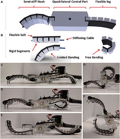
Types and designs
The bulk of the field of soft robotics is based upon the design and construction of robots made completely from compliant materials, with the end result being similar to invertebrates like worms and octopuses. The motion of these robots is difficult to model,[1] as continuum mechanics apply to them, and they are sometimes referred to as continuum robots. Soft Robotics is the specific sub-field of robotics dealing with constructing robots from highly compliant materials, similar to those found in living organisms. Similarly, soft robotics also draws heavily from the way in which these living organisms move and adapt to their surroundings. This allows scientists to use soft robots to understand biological phenomena using experiments that cannot be easily performed on the original biological counterparts. In contrast to robots built from rigid materials, soft robots allow for increased flexibility and adaptability for accomplishing tasks, as well as improved safety when working around humans. These characteristics allow for its potential use in the fields of medicine and manufacturing. However, there exist rigid robots that are also capable of continuum deformations, most notably the snake-arm robot.Also, certain soft robotic mechanics may be used as a piece in a larger, potentially rigid robot. Soft robotic end effectors exist for grabbing and manipulating objects, and they have the advantage of producing a low force that is good for holding delicate objects without breaking them.
In addition, hybrid soft-rigid robots may be built using an internal rigid framework with soft exteriors for safety. The soft exterior may be multifunctional, as it can act as both the actuators for the robot, similar to muscles in vertebrates, and as padding in case of a collision with a person.
Bio-mimicry
Plant cells can inherently produce hydrostatic pressure due to a solute concentration gradient between the cytoplasm and external surroundings (osmotic potential). Further, plants can adjust this concentration through the movement of ions across the cell membrane. This then changes the shape and volume of the plant as it responds to this change in hydrostatic pressure. This pressure derived shape evolution is desirable for soft robotics and can be emulated to create pressure adaptive materials through the use of fluid flow. The following equation models the cell volume change rate:- is the rate of volume change.
- is the cell membrane.
- is the hydraulic conductivity of the material.
- is the change in hydrostatic pressure.
- is the change in osmotic potential.


Another biologically inherent shape changing mechanism is that of hygroscopic shape change. In this mechanism, plant cells react to changes in humidity. When the surrounding atmosphere has a high humidity, the plant cells swell, but when the surrounding atmosphere has a low humidity, the plant cells shrink. This volume change has been observed in pollen grains and pine cone scales.
Manufacturing
Conventional manufacturing techniques, such as subtractive techniques like drilling and milling, are unhelpful when it comes to constructing soft robots as these robots have complex shapes with deformable bodies. Therefore, more advanced manufacturing techniques have been developed. Those include Shape Deposition Manufacturing (SDM), the Smart Composite Microstructure (SCM) process, and 3D multimaterial printing.SDM is a type of rapid prototyping whereby deposition and machining occur cyclically. Essentially, one deposits a material, machines it, embeds a desired structure, deposits a support for said structure, and then further machines the product to a final shape that includes the deposited material and the embedded part. Embedded hardware includes circuits, sensors, and actuators, and scientists have successfully embedded controls inside of polymeric materials to create soft robots, such as the Stickybot and the iSprawl.
SCM is a process whereby one combines rigid bodies of carbon fiber reinforced polymer (CFRP) with flexible polymer ligaments. The flexible polymer act as joints for the skeleton. With this process, an integrated structure of the CFRP and polymer ligaments is created through the use of laser machining followed by lamination. This SCM process is utilized in the production of mesoscale robots as the polymer connectors serve as low friction alternatives to pin joints.
3D printing can now be used to print a wide range of silicone inks using Robocasting also known as direct ink writing (DIW). This manufacturing route allows for a seamless production of fluidic elastomer actuators with locally defined mechanical properties. It further enables a digital fabrication of pneumatic silicone actuators exhibiting programmable bioinspired architectures and motions. A wide range of fully functional softrobots have been printed using this method including bending, twisting, grabbing and contracting motion. This technique avoids some of the drawbacks of conventional manufacturing routes such as delamination between glued parts. Another additive manufacturing method that produces shape morphing materials whose shape is photosensitive, thermally activated, or water responsive. Essentially, these polymers can automatically change shape upon interaction with water, light, or heat. One such example of a shape morphing material was created through the use of light reactive ink-jet printing onto a polystyrene target.[12] Additionally, shape memory polymers have been rapid prototyped that comprise two different components: a skeleton and a hinge material. Upon printing, the material is heated to a temperature higher than the glass transition temperature of the hinge material. This allows for deformation of the hinge material, while not affecting the skeleton material. Further, this polymer can be continually reformed through heating.
Control methods and materials
All soft robots require an actuation system to generate reaction forces, to allow for movement and interaction with its environment. Due to the compliant nature of these robots, soft actuation systems must be able to move without the use of rigid materials that would act as the bones in organisms, or the metal frame that is common in rigid robots. Nevertheless, several control solutions to soft actuation problem exist and have found its use, each possessing advantages and disadvantages. Some examples of control methods and the appropriate materials are listed below.Electric field
One example is utilization of electrostatic force that can be applied in:- Dielectric Elastomer Actuators (DEAs) that use high-voltage electric field in order to change its shape (example of working DEA). These actuators can produce high forces, have high specific power (W kg−1), produce large strains (>1000%), possess high energy density (>3 MJ m−3), exhibit self-sensing, and achieve fast actuation rates (10 ms - 1 s). However, the need for high-voltages quickly becomes the limiting factor in the potential practical applications. Additionally, these systems often exhibit leakage currents, tend to have electrical breakdowns (dielectric failure follows Weibull statistics therefore the probability increases with increased electrode area ), and require pre-strain for the greatest deformation. Some of the new research shows that there are ways of overcoming some of these disadvantages, as shown e.g. in Peano-HASEL actuators, which incorporate liquid dielectrics and thin shell components. These approach lowers the applied voltage needed, as well as allows for self-healing during electrical breakdown.
Thermal
- Shape memory polymers (SMPs) are smart and reconfigurable materials that serve as an excellent example of thermal actuation that can be used for actuation. These materials will "remember" their original shape and will revert to it upon temperature increase. For example, crosslinked polymers can be strained at temperatures above their glass-transition (Tg) or melting-transition (Tm) and then cooled down. When the temperature is increased again, the strain will be released and materials shape will be changed back to the original.[20] This of course suggests that there is only one irreversible movement, but there have been materials demonstrated to have up to 5 temporary shapes. One of the simplest and best known examples of shape memory polymers is a toy called Shrinky Dinks that is made of pre-stretched polystyrene (PS) sheet which can be used to cut out shapes that will shrink significantly when heated. Actuators produced using these materials can achieve strains up to 1000% and have demonstrated a broad range of energy density between <50 kJ m−3 and up to 2 MJ m−3. Definite downsides of SMPs include their slow response (>10 s) and typically low force generated. Examples of SMPs include polyurethane (PU), polyethylene teraphtalate (PET), polyethyleneoxide (PEO) and others.
- Shape memory alloys are behind another control system for soft robotic actuation. Although made of metal, a traditionally rigid material, the springs are made from very thin wires and are just as compliant as other soft materials. These springs have a very high force-to-mass ratio, but stretch through the application of heat, which is inefficient energy-wise.
Pressure difference
- Pneumatic artificial muscles, another control method used in soft robots, relies on changing the pressure inside a flexible tube. This way it will act as a muscle, contracting and extending, thus applying force to what it's attached to. Through the use of valves, the robot may maintain a given shape using these muscles with no additional energy input. However, this method generally requires an external source of compressed air to function.
Sensors
Soft stretch sensors are often used to measure the shape and motion of the robot. These measurements are often then fed into a control system.Uses and applications
Soft robots can be implemented in the medical profession, specifically for invasive surgery. Soft robots can be made to assist surgeries due to their shape changing properties. Shape change is important as a soft robot could navigate around different structures in the human body by adjusting its form. This could be accomplished through the use of fluidic actuation.Soft robots may also be used for the creation of flexible exosuits, for rehabilitation of patients, assisting the elderly, or simply enhancing the user's strength. A team from Harvard created an exosuit using these materials in order to give the advantages of the additional strength provided by an exosuit, without the disadvantages that come with how rigid materials restrict a person's natural movement.
Traditionally, manufacturing robots have been isolated from human workers due to safety concerns, as a rigid robot colliding with a human could easily lead to injury due to the fast-paced motion of the robot. However, soft robots could work alongside humans safely, as in a collision the compliant nature of the robot would prevent or minimize any potential injury.
An application of bio-mimicry via soft robotics is in ocean or space exploration. In the search for extraterrestrial life, scientists need to know more about extraterrestrial bodies of water, as water is the source of life on Earth. Soft robots could be used to mimic sea creatures that can efficiently maneuver through water. Such a project was attempted by a team at Cornell in 2015 under a grant through NASA’s Innovative Advanced Concepts (NIAC). The team set out to design a soft robot that would mimic a lamprey or cuttlefish in the way it moved underwater, in order to efficiently explore the ocean below the ice layer of Jupiter's moon, Europa. But exploring a body of water, especially one on another planet, comes with a unique set of mechanical and materials challenges.
Mechanical Considerations in Design
Soft robots, particularly those designed to imitate life, often must experience cyclic loading in order to move or do the tasks for which they were designed. For example, in the case of the lamprey- or cuttlefish-like robot described above, motion would require electrolyzing water and igniting gas, causing a rapid expansion to propel the robot forward. This repetitive and explosive expansion and contraction would create an environment of intense cyclic loading on the chosen polymeric material. A robot underwater and/or on Europa would be nearly impossible to patch up or replace, so care would need to be taken to choose a material and design that minimizes initiation and propagation of fatigue-cracks. In particular, one should choose a material with a fatigue limit, or a stress-amplitude frequency above which the polymer’s fatigue response is no longer dependent on the frequency.Secondly, because soft robots are made of highly compliant materials, one must consider temperature effects. The yield stress of a material tends to decrease with temperature, and in polymeric materials this effect is even more extreme. At room temperature and higher temperatures, the long chains in many polymers can stretch and slide past each other, preventing the local concentration of stress in one area and making the material ductile. But most polymers undergo a ductile-to-brittle transition temperature below which there is not enough thermal energy for the long chains to respond in that ductile manner, and fracture is much more likely. The tendency of polymeric materials to turn brittle at cooler temperatures is in fact thought to be responsible for the Space Shuttle Challenger disaster, and must be taken very seriously, especially for soft robots that will be implemented in medicine. A ductile-to-brittle transition temperature need not be what one might consider "cold," and is in fact characteristic of the material itself, depending on its crystallinity, toughness, side-group size (in the case of polymers), and other factors
Efficiency of motion for Robotic
In the motion efficiency of the robot, it requires sufficient energy efficiency to supply electronic equipment that drives the actuator or output system and if possible energy is absorbed only in nano amperes and micro amperes.
Smart Generator Technology
The mechanical generator systems, developed and patented by Kinetron, are devices that transform human or mechanical kinetic energy into electrical energy to power electronic products.This transformation is realized by a highly efficient micro generators and micro precision mechanics, to guarantee the highest efficiency and highest power density in the market.
Besides energy generation, Kinetron’s smart generator systems can be equipped with highly efficient rectifying, charging and storing circuits and can be configured to gather, process and (wirelessly) transmit data about the use or movement of the system. This enables the creation of self-powered smart.
__________________________________________________________________________________
Gen. Mac Tech Zone MARIA PREFER
( Moving Area Robotics In Allow Precision Reliability Flexibility Efficiency of motion )
for ROBOTIC .
e- S H I N to A / D / S Tour Route and e- STAR_C
__________________________________________________________________________________
Tidak ada komentar:
Posting Komentar