
S T A R __ C

S ( Stop Watch )
TIMER ( T )

A ( Alarm Electronic )

C ( Clock Electronic )
S T A R __ C
_________________________________________________________________________________
STOP WATCH in e- S H I N to A/D/S Tour Route

A stopwatch is a handheld timepiece designed to measure the amount of time that elapses between its activation and deactivation. A large digital version of a stopwatch designed for viewing at a distance, as in a sports stadium, is called a stop clock.
A stopwatch is a handheld timepiece designed to measure the amount of time that elapses between its activation and deactivation. A large digital version of a stopwatch designed for viewing at a distance, as in a sports stadium, is called a stopclock. In manual timing, the clock is started and stopped by a person pressing a button. In fully automatic time, both starting and stopping are triggered automatically, by sensors.
The timing functions are traditionally controlled by two buttons on the case. Pressing the top button starts the timer running, and pressing the button a second time stops it, leaving the elapsed time displayed. A press of the second button then resets the stopwatch to zero. The second button is also used to record split times or lap times. When the split time button is pressed while the watch is running, the display freezes then starts then freezes again, allowing the elapsed time to that point to be read, but the watch mechanism continues running to record total elapsed time. Pressing the split button a second time allows the watch to resume display of total time.

Stopwatch function in Casio wristwatch.

Digital electronic stopwatches are available which, due to their crystal oscillator timing element, are much more accurate than mechanical timepieces. Because they contain a microchip, they often include date and time-of-day functions as well. Some may have a connector for external sensors, allowing the stopwatch to be triggered by external events, thus measuring elapsed time far more accurately than is possible by pressing the buttons with one's finger. Stopwatches that count by 1/100 of a second are commonly mistaken as counting milliseconds, rather than centiseconds. The first digital timer used in organized sports was the Digitimer, developed by Cox Electronic Systems, Inc. of Salt Lake City Utah (1971). It utilized a Nixie-tube readout and provided a resolution of 1/1000 second. Its first use was in ski racing but was later used by the World University Games in Moscow, Russia, the U.S. NCAA, and in the Olympic trials.
The device is used when time periods must be measured precisely and with a minimum of complications. Laboratory experiments and sporting events like sprints are good examples.
The stopwatch function is also present as an additional function of many electronic devices such as wristwatches, cell phones, portable music players, and computers.
Even though stopwatches are created to be more accurate, humans are
still prone to make mistakes every time they use one. Normally, humans
will take about 180–200 milliseconds to detect and respond to visual stimulus. Therefore, most of the measurement errors happen for that reason. To get more accurate results, most researchers use the propagation of uncertainty equation in order to reduce any error in experiments.

 and 0.05 will be
  .
.
is the sum of the uncertainty between
and
 and 0.05 will be .
In most science experiments, researchers will normally use SI or the International System of Units on any of their experiments. For stopwatches, the units of time that are generally used when observing a stopwatch are minutes, seconds, and 'one hundredth of a second'.
_________________________________________________________________________________
TIMER in e- S H I N to A/D/S tour Route
Timer is a clock that controls the sequence of an event while counting in fixed intervals of time. A Timer is used for producing precise time delay. ... An example could be setting up an alarm which triggers at a point of time or after a period of time. Most of the processors/controllers have inbuilt Timers.
A time switch (also called a timer switch, or simply timer) is a timer that operates an electric switch controlled by the timing mechanism. The switch may be connected to an electric circuit operating from mains power, including via a relay or contactor; or low voltage, including battery-operated equipment in vehicles.
In general, there are three types of PLC timer delays, ON-delay timer, OFF-delay timer and retentive timer on
Timer in Operating System:As all we know that it is only the operating system that has full control over the CPU,and it is the primary duty of operating system to prevent user programs from getting stuck into an infinite loop or not calling to system services and never returning control back to the operating system..
A timer which counts upwards from zero for measuring elapsed time is often called a stopwatch, while a device which counts down from a specified time interval is more usually called a timer. A simple example of this type is an hourglass. Working method timers have two main groups: Hardware and Software timers.
CPU protection: CPU usage is protected by using the timer device, the associated timer interrupts, and OS code called the scheduler. While running in user mode, the CPU cannot change the timer value or turn off the timer interrupt, because these require privileged operations.
Electronic Timer Circuit
the electronic timer circuit describe below can be used by the student as a clock while they are preparing for the competitive exams.

It
will give them audio visual sound after the pre set time interval. In
our electronic timer circuit it is 15 minutes hence it will give an
alarm after every 15 minutes. The timer could be programmed for other
periods as well. By calibrating the variable resistor by some hit and
trial method, you can vary the time period. We have also provided a
reset switch so that you can reset it when you are required to start it
again.
The
circuit is built around CD4060 and few more components. IC CD4060 is 14
stage ripple carry binary counter, divider and an oscillator. Its
built-in oscillator is main feature of this IC that’s why it can be used
in numerous applications like flasher, clock generator in timer
circuits.
Here
IC1 is working as frequency dividing circuit. In this internal
oscillator stage is made using resistor and capacitor which can be
connected to pin 11,10 and 9. A capacitor is connected to pin 9 and pin
11 and 10 is connected with a resistor. Most importantly, pin 10 is
connected to a variable resistor so that we can select different
frequency range. We are also using a fixed resistor so that while
adjusting pot pin 10 values may not fall to zero. With the components
explained, alarm can be adjusted for 15 minutes at the output. When
power is on the pulse at the junction R3 and C2 resets the counter and
counting starts. And when counter reaches bit 14(Q13), pin 3 goes high
so that the buzzer connected with the transistor turns on. We have
provided a reset switch S1 at pin 12 which when press momentarily will
reset all counter and oscillation starts over again.
If
you want to change the time period of oscillator you can do it just by
changing the value of component R1, R2 and VR1.One thing we must take
care that value of resistor connected to pin 10 including variable
resistor should be 10 times less than resistor connected to pin 11. We
have connected to pin 12 reset input to ground with a capacitor and
resistor because when power is applied it initially behaviors as a short
and prevents the IC from getting a ground potential through the
resistor. And with the few milliseconds the capacitor charges and makes
the pin potential to ground level. This ensures that the IC initiates
counting from zero so that we will get regular time period making the
result more reliable.
During
testing of circuit you can connect the output at Q10 and Q13 means at
pin 15 and pin 12 .It gives lesser division and corresponding less time
cycle of operation. It is tedious to wait that the circuit is working or
not , so you can also make hit and trial by connecting different value
of R1 ,R2, VR1 and you will get the output soon.
 |
LED
Light emitting diodes...
|
 |
Resistor
Resistor
is a passive component used to control current in a circuit. Its
resistance is given by the ratio of voltage applied across its terminals
to the current passing through it. Thus a particular value of resistor,
for fixed voltage, limits the current through it. They are omnipresent
in...
|
 |
Capacitor
Capacitor
is a passive component used to store charge. The charge (q) stored in a
capacitor is the product of its capacitance (C) value and the voltage
(V) applied to it. Capacitors offer infinite reactance to zero frequency
so they are used for blocking DC components or bypassing the AC
signals. The capacitor...
|

A digital timing diagram is a representation of a set of signals in the time domain. A timing diagram can contain many rows, usually one of them being the clock. It is a tool that is commonly used in digital electronics, hardware debugging, and digital communications.
Digital timing diagram
A digital timing diagram is a representation of a set of signals in the time domain. A timing diagram can contain many rows, usually one of them being the clock. It is a tool that is commonly used in digital electronics, hardware debugging, and digital communications. Besides providing an overall description of the timing relationships, the digital timing diagram can help find and diagnose digital logic hazards.
Diagram convention
Most timing diagrams use the following conventions:- Higher value is a logic one
- Lower value is a logic zero
- A slot showing a high and low is an either or (such as on a data line)
- A Z indicates high impedance
- A greyed out slot is a don't-care or indeterminate.
Example: SPI bus timing

A timing diagram for the Serial Peripheral Interface Bus
SPI operates in the following way:
- The master determines an appropriate CPOL & CPHA value
- The master pulls down the slave select (SS) line for a specific slave chip
- The master clocks SCK at a specific frequency
- During each of the 8 clock cycles the transfer is full duplex:
- The master writes on the MOSI line and reads the MISO line
- The slave writes on the MISO line and reads the MOSI line
- When finished the master can continue with another byte transfer or pull SS high to end the transfer
Note that for CPHA=1 the MISO & MOSI lines are undefined until after the first clock edge and are also shown greyed-out before that.
A more typical timing diagram has just a single clock and numerous data lines
Timer
A timer is a specialized type of clock used for measuring specific time intervals. Timers can be categorized into two main types. A timer which counts upwards from zero for measuring elapsed time is often called a stopwatch, while a device which counts down from a specified time interval is more usually called a timer. A simple example of this type is an hourglass. Working method timers have two main groups: Hardware and Software timers.
Most timers give an indication that the time interval that had been set has expired.
Time switches, timing mechanisms which activate a switch, are sometimes also called "timers".
Hardware timers
Mechanical timers
Mechanical timers use clockwork to measure time.[1] Manual timers are typically set by turning a dial to the time interval desired; turning the dial stores energy in a mainspring to run the mechanism. They function similarly to a mechanical alarm clock; the energy in the mainspring causes a balance wheel to rotate back and forth.[1] Each swing of the wheel releases the gear train to move forward by a small fixed amount, causing the dial to move steadily backward until it reaches zero when a lever arm strikes a bell. The mechanical kitchen timer was invented in 1926 by Thomas Norman Hicks.[1] Some less accurate, cheaper mechanisms use a flat paddle called a fan fly that spins against air resistance; low-precision mechanical egg-timers are sometimes of this type.The simplest and oldest type of mechanical timer is the hourglass, in which a fixed amount of sand drains through a narrow opening from one chamber to another to measure a time interval.
Electromechanical timers

An electromechanical cam timer uses a small synchronous AC motor turning a cam against a comb of switch contacts. The AC motor is turned at an accurate rate by the alternating current, which power companies carefully regulate. Gears drive a shaft at the desired rate, and turn the cam. The most common application of this timer now is in washers, driers and dishwashers. This type of timer often has a friction clutch between the gear train and the cam, so that the cam can be turned to reset the time.
Electromechanical timers survive in these applications because mechanical switch contacts may still be less expensive than the semiconductor devices needed to control powerful lights, motors and heaters.
In the past, these electromechanical timers were often combined with electrical relays to create electro-mechanical controllers. Electromechanical timers reached a high state of development in the 1950s and 1960s because of their extensive use in aerospace and weapons systems. Programmable electromechanical timers controlled launch sequence events in early rockets and ballistic missiles. As digital electronics has progressed and dropped in price, electronic timers have become more advantageous.
Electronic timers

A simple digital timer. The internal components—including the circuit board with control chip and LED display, a battery, and a buzzer—are visible.
Many timers are now implemented in software. Modern controllers use a programmable logic controller (PLC) rather than a box full of electromechanical parts. The logic is usually designed as if it were relays, using a special computer language called ladder logic. In PLCs, timers are usually simulated by the software built into the controller. Each timer is just an entry in a table maintained by the software.
Digital timers are used in safety devices such as a gas timer.
Software timers
These types of timers are not devices nor parts of devices; they exist only as computer code. They rely on the accuracy of a clock generator usually built into a hardware device that runs the software.Software applications
Nowadays when people are using more and more mobile phones, there are also timer apps that mimic the old mechanical timer, but which have also highly sophisticated functions. These apps are also easier to use daily, because they are available at once, without any need to purchase or carry the separate devices, as today timer is just a software application on a phone or tablet. Some of these apps are countdown timers, stopwatch timers, etc. These timer apps can be used for tracking working or training time, motivating children to do tasks, replacing an hour glass in board games, or for the traditional purpose for tracking time when cooking and baking.Apps may be superior to hour glasses, or to mechanical timers. Hour glasses are not precise and clear, and they can jam. Mechanical timers lack the customization that applications support, such as sound volume adjustments for individual needs. Most applications will also offer selectable alarm sounds.
Some timer applications can help children to understand the concept of time, help them to finish tasks in time, and help them to get motivated. These applications are especially used with children with special needs like ADHD, Down syndrome, etc., but everybody else can also benefit from them.
Other types
Computer systems usually have at least one hardware timer. These are typically digital counters that either increment or decrement at a fixed frequency, which is often configurable, and which interrupt the processor when reaching zero. An alternative design uses a counter with a sufficiently large word size that it will not reach its overflow limit before the end of life of the system.More-sophisticated timers may have comparison logic to compare the timer value against a specific value, set by software, that triggers some action when the timer value matches the preset value. This might be used, for example, to measure events or generate pulse width modulated wave forms to control the speed of motors (using a class D digital electronic amplifier).
One specialist use of hardware timers in computer systems is as watchdog timers, that are designed to perform a hardware reset of the system if the software fails.
555 timer IC
The 555 timer IC is an integrated circuit (chip) used in a variety of timer, pulse generation, and oscillator applications. The 555 can be used to provide time delays, as an oscillator, and as a flip-flop element. Derivatives provide two or four timing circuits in one package.Introduced in 1972 by Signetics, the 555 is still in widespread use due to its low price, ease of use, and stability. It is now made by many companies in the original bipolar and in low-power CMOS technologies. As of 2003, it was estimated that 1 billion units were manufactured every year. The 555 is the most popular integrated circuit ever manufactured.

Signetics NE555 in 8-pin DIP package
| |
| Type | Active, Integrated circuit |
|---|---|
| Invented | Hans Camenzind |
| First production | 1971 |
| Electronic symbol | |
 Internal block diagram[ | |
Pinout
The typical pinout of the 555 and 556 IC packages are as follows:| 555 Pin# | 556 Pin# | Pin name | Pin direction | Pin purpose |
|---|
| 1 | 7 | GND | Power | Ground supply: this pin is the ground reference voltage (zero volts). |
| 2 | 6, 8 | TRIG | Input | Trigger: when the voltage at this pin falls below 1⁄2 of CONT pin voltage (1⁄3 VCC except when CONT is driven by an external signal), the OUT pin goes high and a timing interval starts. As long as this pin continues to be kept at a low voltage, the OUT pin will remain high. |
| 3 | 5,9 | OUT | Output | Output: this is a push-pull (P.P.) output that is driven to either a low state (ground supply at GND pin) or a high state (positive supply at VCC pin minus approximately 1.7 Volts). (Note: For CMOS timers, the high state is driven to VCC.) When bipolar timers are used in applications where the output drives a TTL input, a 100 to 1000 pF decoupling capacitor may need to be added to prevent double triggering. |
| 4 | 4,10 | RESET | Input | Reset: a timing interval may be reset by driving this pin to GND, but the timing does not begin again until this pin rises above approximately 0.7 Volts. This pin overrides TRIG (trigger), which overrides THRES (threshold). In most applications this pin is not used, thus it should be connected to VCC to prevent electrical noise causing a reset. |
| 5 | 3,11 | CONT | Input | Control (or Control Voltage): this pin provides access to the internal voltage divider (2⁄3 VCC by default). By applying a voltage to the CONT input one can alter the timing characteristics of the device. In most applications this pin is not used, thus a 10 nF decoupling capacitor (film or C0G) should be connected between this pin and GND to ensure electrical noise doesn't affect the internal voltage divider. This control pin input can be used to build an astable multivibrator with a frequency-modulated output. |
| 6 | 2,12 | THRES | Input | Threshold: when the voltage at this pin is greater than the voltage at CONT pin (2⁄3 VCC except when CONT is driven by an external signal), then the timing (OUT high) interval ends. |
| 7 | 1,13 | DISCH | Output | Discharge: this is an open-collector (O.C.) output (CMOS timers are open-drain), which can be used to discharge a capacitor between intervals, in phase with output. |
| 8 | 14 | VCC | Power | Positive supply: the guaranteed voltage range of bipolar timers is typically 4.5 to 15 Volts (some timers are spec'ed for up to 16 Volts or 18 Volts), though most will operate as low as 3 Volts. (Note: CMOS timers have a lower minimum voltage rating, which varies depending on the part number.) See the supply min and max columns in the derivatives table. For bipolar timers, a decoupling capacitor is required because of current surges during output switching. |

Modes
The IC 555 has three operating modes:- Astable (free-running) mode – the 555 can operate as an electronic oscillator. Uses include LED and lamp flashers, pulse generation, logic clocks, tone generation, security alarms, pulse position modulation and so on. The 555 can be used as a simple ADC, converting an analog value to a pulse length (e.g., selecting a thermistor as timing resistor allows the use of the 555 in a temperature sensor and the period of the output pulse is determined by the temperature). The use of a microprocessor-based circuit can then convert the pulse period to temperature, linearize it and even provide calibration means.
- Monostable mode – in this mode, the 555 functions as a "one-shot" pulse generator. Applications include timers, missing pulse detection, bounce-free switches, touch switches, frequency divider, capacitance measurement, pulse-width modulation (PWM) and so on.
- Bistable (schmitt trigger) mode – the 555 can operate as a flip-flop, if the DIS pin is not connected and no capacitor is used. Uses include bounce-free latched switches.
Astable


In the first pulse, the capacitor charges from zero to two-thirds of the supply voltage, however, in later pulses, it only charges from one-third to two-thirds of the supply voltage. Consequently, the first pulse have a longer high time interval compared to later pulses. Moreover, the capacitor charges through both resistors but only discharges through , thus the high interval is longer than the low interval. This is shown in the following equations. Where the high interval of each pulse is given by:


Particularly with bipolar 555s, low values of must be avoided so that the output stays saturated near zero volts during discharge, as assumed by the above equation. Otherwise the output low time will be greater than calculated above. The first cycle will take appreciably longer than the calculated time, as the capacitor must charge from 0V to 2⁄3 of VCC from power-up, but only from 1⁄3 of VCC to 2⁄3 of VCC on subsequent cycles.
To have an output high time shorter than the low time (i.e., a duty cycle less than 50%) a fast diode (i.e. 1N4148 signal diode) can be placed in parallel with R2, with the cathode on the capacitor side. This bypasses R2 during the high part of the cycle so that the high interval depends only on R1 and C, with an adjustment based the voltage drop across the diode. The voltage drop across the diode slows charging on the capacitor so that the high time is a longer than the expected and often-cited ln(2)*R1C = 0.693 R1C. The low time will be the same as above, 0.693 R2C. With the bypass diode, the high time is

The operation of RESET in this mode is not well-defined. Some manufacturers' parts will hold the output state to what it was when RESET is taken low, others will send the output either high or low.
The astable configuration, with two resistors, cannot produce a 50% duty cycle. To produce a 50% duty cycle, eliminate R1, disconnect pin 7 and connect the supply end of R2 to pin 3, the output pin. This circuit is similar to using an inverter gate as an oscillator, but with fewer components than the astable configuration, and a much higher power output than a TTL or CMOS gate. The duty cycle for either the 555 or inverter-gate timer will not be precisely 50% and will change depending on the load that the output is also driving while high (longer duty cycles for greater loads) due to the fact the timing network is supplied from the device's output pin, which has different internal resistances depending on whether it is in the high or low state (high side drivers tend to be more resistive). An alternate method to set the duty cycle practically, is to connect a diode parallel to pin 6 & 7. The operation of the diode when connected is explained above. The resultant duty cycle is given as D=R2/(R1+R2). If a potentiometer is used to supply R1 and R2, R1 + R2 is constant. The duty cycle then varies with the potentiometer at a constant frequency. A series resistor of 100 ohms must be added to each R1 and R2 to limit peak current of the transistor(within) when R1 and R2 are at minimum level. This method of adding a diode has a restriction of choosing R1 and R2 values. An alternate way is to add a JK flip-flop to the output of non-symmetrical square wave generator. But, with this the output frequency is one half of the timer.
Monostable

.png)
Assume initially the output of the monostable is zero, the output of flip-flop(Q bar) is 1 so that the discharging transistor is on and voltage across capacitor is zero. One of the input of upper comparator is at 2/3 of supply voltage and other is connected to capacitor. For lower comparator, one of the input is trigger pulse and other is connected at 1/3 of supply voltage. Now the capacitor charges towards supply voltage(Vcc). When the trigger input is applied at trigger pin the output of lower comparator is 0 and upper comparator is 0. The output of flip-flop remains unchanged therefore the output is 0. when the voltage across capacitor crosses the 1/3 of the vcc the output of lower comparator changes from 0 to 1. Therefore, the output of monostable is one and the discharging transistor is still off and voltage across capacitor charges towards vcc from 1/3 of vcc,
When the voltage across capacitor crosses 2/3 of VCC, the output of upper comparator changes from 0 to 1, therefore the output of monostable is 0 and the discharging transistor is on and capacitor discharges through this transistor as it offers low resistance path. The cycle repeats continuously. The charging and discharging of capacitor depends on the time constant RC.
The voltage across capacitor is given by vc = Vcc(1-e^(-t/RC)) at t=T, vc =(2/3)Vcc therefore, 2/3Vcc=Vcc(1-e^(-T/RC)), T=RC ln(3), T=1.1 RC (seconds)
The output pulse width of time t, which is the time it takes to charge C to 2⁄3 of the supply voltage, is given by

While using the timer IC in monostable mode, the main disadvantage is that the time span between any two triggering pulses must be greater than the RC time constan Conversely, ignoring closely spaced pulses is done by setting the RC time constant to be larger than the span between spurious triggers. (Example: ignoring switch contact bouncing.)
Bistable

A 555 timer can be used to create a Schmitt trigger which converts a noisy input into a clean digital output. The input signal should be connected through a series capacitor which then connects to the trigger and threshold pins. A resistor divider, from VCC to GND, is connected to the previous tied pins. The reset pin is tied to VCC.
Specifications

Texas Instruments NE555 in DIP-8 and SO-8 packages
| Supply voltage (VCC) | 4.5 to 15 V |
| Supply current (VCC = +5 V) | 3 to 6 mA |
| Supply current (VCC = +15 V) | 10 to 15 mA |
| Output current (maximum) | 200 mA |
| Maximum Power dissipation | 600 mW |
| Power consumption (minimum operating) | 30 mW@5V, 225 mW@15V |
| Operating temperature | 0 to 75 °C |
Packages
In 1972, Signetics originally released the 555 timer in DIP-8 and TO5-8 metal can packages, and the 556 timer was released in DIP-14 package.Currently, the 555 is available in through-hole packages as DIP-8 and SIP-8 (both 2.54mm pitch), and surface-mount packages as SO-8 (1.27mm pitch), SSOP-8 / TSSOP-8 / VSSOP-8 (0.65mm pitch), BGA (0.5mm pitch). The Microchip Technology MIC1555 is a 555 CMOS timer with 3 fewer pins available in SOT23-5 (0.95mm pitch) surface mount package.
The dual 556 timer is available in through hole packages as DIP-14 (2.54mm pitch), and surface-mount packages as SO-14 (1.27mm pitch) and SSOP-14 (0.65mm pitch).
Derivatives
Numerous companies have manufactured one or more variants of the 555, 556, 558 timers over the past decades as many different part numbers. The following is a partial list: AMD, California Eastern Labs, CEMI, Custom Silicon Solutions, Diodes Inc, ECG Philips, Estek, Exar, Fairchild, Gemini, GoldStar, Harris, HFO, Hitachi, IK Semicon, Intersil, JRC, Lithic Systems, Maxim, Micrel, MOS, Motorola, ON, Microchip, National, NEC, NTE Sylvania, NXP, Philips, Raytheon, RCA, Renesas, Sanyo, Signetics, Silicon General, Solid State Scientific, STMicroelectronics, Teledyne, TI, Unisonic, Wing Shing, X-REL, Zetex.| Manufacturer | Part Number |
Production Active |
IC Process |
Timer Total |
Supply Min (Volt) |
Supply Max (Volt) |
5V Supply Iq (μA) |
Frequency Max (MHz) |
Remark | Datasheet |
|---|---|---|---|---|---|---|---|---|---|---|
| Custom Silicon Solutions | CSS555 | Yes | CMOS | 1 | 1.2 | 5.5 | 4.3 | 1.0 | Low Voltage, Lowest Current Internal EEPROM configuration |
[25] [26] |
| Diodes Incorporated | ZSCT155 | No | CMOS | 1 | 0.9 | 6 | 150 | 0.33 | Lowest supply voltage | [27] |
| Intersil | ICM7555 | Yes | CMOS | 1 | 2 | 18 | 40 | 1.0 | Lowest current of common parts | [14] |
| Intersil | ICM7556 | Yes | CMOS | 2 | 2 | 18 | 80 | 1.0 | Lowest current of common parts | [14] |
| Japan Radio Company | NJM555 | Yes | Bipolar | 1 | 4.5 | 16 | 3000 | 0.1* | SIP-8 package | [23] |
| Microchip Technology | MIC1555 | Yes | CMOS | 1* | 2.7 | 18 | 240 | 5.0* | SOT23-5 package | [24] |
| ON Semiconductor | LM555 | Yes | Bipolar | 1 | 4.5 | 16 | 3000 | 0.1* | — | [28] |
| Signetics | NE555 | No | Bipolar | 1 | 4.5 | 16 | 3000 | 0.1* | First 555 timer DIP-8 and TO5-8 package |
[4] [13] [29] [2] |
| Signetics | NE556 | No | Bipolar | 2 | 4.5 | 16 | 6000 | 0.1* | First 556 timer DIP-14 package |
[13][2] |
| Signetics | NE558 | No | Bipolar | 4* | 4.5 | 18 | 4800* | 0.1* | First 558 timer DIP-16 package |
[2] |
| Texas Instruments | LM555 | Yes | Bipolar | 1 | 4.5 | 18 | 3000 | 0.1* | — | [21] |
| Texas Instruments | LM556 | Yes | Bipolar | 2 | 4.5 | 16 | 6000 | 0.1* | — | [30] |
| Texas Instruments | LMC555 | Yes | LinCMOS | 1 | 1.5 | 15 | 100 | 3.0 | DSBGA-8 package (smallest 555) | [15] |
| Texas Instruments | NE555 | Yes | Bipolar | 1 | 4.5 | 16 | 3000 | 0.1* | Similar to Signetic NE555 | [1] |
| Texas Instruments | NE556 | Yes | Bipolar | 2 | 4.5 | 16 | 6000 | 0.1* | Similar to Signetic NE556 | [18] |
| Texas Instruments | TLC551 | Yes | LinCMOS | 1 | 1 | 15 | 170 | 1.8 | Lowest voltage of active parts | [17] |
| Texas Instruments | TLC552 | Yes | LinCMOS | 2 | 1 | 18 | 340 | 2.8 | Lowest voltage of active parts | [31] |
| Texas Instruments | TLC555 | Yes | LinCMOS | 1 | 2 | 15 | 170 | 2.1 | — | [16] |
| Texas Instruments | TLC556 | Yes | LinCMOS | 2 | 2 | 15 | 340 | 2.1 | — | [32] |
| X-REL Semiconductor | XTR655 | Yes | — | 1 | 2.8 | 5.5 | 170 | 4.0 | Extreme temp (-60°C to +230°C) | [33] |

Die of a NE556 dual timer manufactured by STMicroelectronics.

Die of a NE558D quad timer manufactured by Signetics.
- Table notes
- All information in the above table was pulled from references in the datasheet column, except where denoted below.
- For "Timer Total" column, a "*" denotes parts that are missing 555 timer features.
- For "Iq" column, a 5 volt supply was chosen as a common voltage to make it easier to compare. The value for Signetics NE558 is an estimate, because NE558 datasheets don't state Iq at 5V.[The value listed in this table was estimated by comparing the 5V to 15V ratio of other bipolar datasheets, then derating the 15V parameter for the NE558 part, which is denoted by the "*".
- For "Frequency Max" column, a "*" denotes values that may not be the actual maximum frequency limit of the part. The MIC1555 datasheet discusses limitations from 1 to 5 MHz.Though most bipolar timers don't state the maximum frequency in their datasheets, they all have a maximum frequency limitation of hundreds of kHz across their full temperature range. Section 8.1 of the Texas Instruments NE555 datasheet states a value of 100 kHz, and their website shows a value of 100 kHz in timer comparison tables, which is overly conservative. In Signetics App Note 170, states that most devices will oscillate up to 1 MHz, however when considering temperature stability it should be limited to about 500 kHz.
- Table manufacturer notes
- Fairchild Semiconductor was sold to ON Semiconductor in 2016.
- Micrel was sold to Microchip Technology in 2015.
- National Semiconductor was sold to Texas Instruments in 2011.
- Signetics was sold to Philips Semiconductor in 1975, later to NXP Semiconductors in 2006.
- Zetex Semiconductors was sold to Diodes Incorporated in 2008.
556 dual timer
The dual version is called 556. It features two complete 555s in a 14 pin package. Only the two power supply pins are shared between the two timers. Bipolar version are currently available, such as the NE556 and LM556. CMOS versions are currently available, such as the Intersil ICM7556 and Texas Instruments TLC556 and TLC552, see derivatives table.558 quad timer

Pinout of 558 quad timer (16 pins). The 558 timers are different than 555 timer (obsolete part)
Partial list of differences between 558 and 555 chips:
- One VCC and one GND, similar to 556 chip.
- Four "Reset" are tied together internally to one external pin (558).
- Four "Control Voltage" are tied together internally to one external pin (558).
- Four "Triggers" are falling-edge sensitive (558), instead of level sensitive (555).
- Two resistors in the voltage divider (558), instead of three resistors (555).
- One comparator (558), instead of two comparators (555).
- Four "Output" are open-collector (O.C.) type (558), instead of push-pull (P.P.) type (555). Since the 558 outputs are open-collector, pull-up resistors are required to "pull up" the output to the positive voltage rail when the output is in a high state. This means the high state only sources a small amount of current through the pull-up resistor.
Time switch
A time switch (also called a timer switch, or simply timer) is a timer that operates an electric switch controlled by the timing mechanism.The switch may be connected to an electric circuit operating from mains power, including via a relay or contactor; or low voltage, including battery-operated equipment in vehicles. It may be built into power circuits (as with a central heating or water heater timer), plugged into a wall outlet with equipment plugged into the timer instead of directly into the power point; or built into equipment as, for example, a sleep timer that turns off a television receiver after a set period.
The mechanism may be mechanical (e.g., clockwork; rarely used nowadays), electromechanical (e.g., a slowly rotating geared motor that mechanically operates switches) or electronic, with semiconductor timing circuitry and switching devices and no moving parts.
The timer may switch equipment on, off, or both, at a preset time or times, after a preset interval, or cyclically. A countdown time switch switches power, usually off, after a preset time. A cyclical timer switches equipment both on and off at preset times over a period, then repeats the cycle; the period is usually 24 hours or 7 days.
For example, a central heating timer may supply heat for a specified period during the morning and evening every weekday, and all day on weekends. A timer for an unattended slow cooker may switch on automatically at a time and for a period suitable to have food ready at mealtime. Likewise, a coffee maker may turn itself on early in the morning in time for awakening residents to have fresh coffee already brewed for them.
Timers may do other processing or have sensors; for example, a timer may switch on lights only during hours of darkness, using a seasonal algorithm or light sensor. Combining the two allows a light to come on at sundown and go off at midnight, for example.
An astronomical (or astronomic) timer calculates dawn and dusk times for each day of the year based on the latitude and longitude (or just north/central/south and time zone on more cheaply made ones), and the day of the year (month and date), programmed by the user upon installation in addition to the usual time of day, except in the case of GPS enabled astronomic timers wherein all
programming is fully automatic. This eliminates the need for a photocell (which may be repeatedly triggered on and off by the light which it operates) or for repeatedly re-setting a regular timer for seasonal changes in the length of day or for daylight-saving time. This allows exterior lighting like a porch light fixture to be controlled by simply replacing its indoor wall switch, or doing the same for a lamp in a dark interior corner (away from a window) by simply plugging-in a self-adjusting lamp timer.
Time switches can be used for many purposes, including saving electric energy by consuming it only when required, switching equipment on, off, or both at times required by some process, and home security (for example switching lights in a pattern that gives the impression that premises are attended) to reduce the likelihood of burglary or prowling.
Among applications are lighting (interior, exterior, and street lighting), cooking devices such as ovens, washing machines, and heating and cooling of buildings and vehicles. Built-in automatic washing machine controllers are examples of very complex electromechanical and electronic timers cycles, starting and stopping many processes including pumps and valves to fill and empty the drum with water, heating, and rotating at different speeds, with different combinations of settings for different fabrics.
 A 24-hour cyclical electromechanical UK time switch showing current time 06:15 and set to be on from 07:00 to 07:45 and 20:00 to 22:00.
 Digital in-wall timer switch with battery for uninterrupted time keeping


________________________________________________________________________________
ALARM ELECTRONIC IN e- S H I N t0 A/D/S Tour route
Circuit. In electronics, a circuit is a closed path that allows electricity to flow from one point to another. It may include various electrical components, such as transistors, resistors, and capacitors, but the flow is unimpeded by a gap or break in the circuit
The basic burglar alarm is actually an electrical circuit which is placed in the entrance of a building. The circuit contains electricity and enables it to flow between two points of opposite charge. When you open the door, a part of the circuit is opened. Its pathway is disrupted and current stops flowing.
The current powers the relay's electromagnet, so the buzzer circuit stays open. When you move the magnet by opening the door, the spring snaps the switch back into the open position. This cuts off the current and closes the relay, sounding the alarm. You can also build this sort of system into a window.
Circuit in science:
A closed path through which an electric current flows or may flow. ♦ Circuits in which a power source is connected to two or more components (such as light bulbs, or logic gates in a computer circuit), one after the other, are called series circuits.
In theoretical computer science, a circuit is a model of computation in which input values proceed through a sequence of gates, each of which computes a function. Circuits of this kind provide a generalization of Boolean circuits and a mathematical model for digital logic circuits .
Circuit (computer science)
In theoretical computer science, a circuit is a model of computation in which input values proceed through a sequence of gates, each of which computes a function. Circuits of this kind provide a generalization of Boolean circuits and a mathematical model for digital logic circuits. Circuits are defined by the gates they contain and the values the gates can produce. For example, the values in a Boolean circuit are boolean values, and the circuit includes conjunction, disjunction, and negation gates. The values in an integer circuit are sets of integers and the gates compute set union, set intersection, and set complement, as well as the arithmetic operations addition and multiplication.computer science, a circuit is a model of computation in which input values proceed through a sequence of gates, each of which computes a function.


__________________________________________________________________________________
C ( Clock ) in e-S H I N to A/D/S Tour Route

Time clock
A time clock, sometimes known as a clock card machine or punch clock or time recorder, is a device that records start and end times for hourly employees at a place of business.
In mechanical time clocks, this was accomplished by inserting a heavy paper card, called a time card, into a slot on the time clock. When the time card hit a contact at the rear of the slot, the machine would print day and time information (a timestamp) on the card.
One or more time cards could serve as a timesheet or provide the data to fill one. This allowed a timekeeper to have an official record of the hours an employee worked to calculate the pay owed an employee.
Electronic time clock
Basic time clock
A basic time clock will just stamp the date and time on a time card, similar to a parking validation machine. These will usually be activated by a button that a worker must press to stamp their card, or stamp upon full insertion. Some machines use punch hole cards instead of stamping, which can facilitate automated processing on machinery not capable of optical character recognition.There are also variations based on manufacture and machine used, and whether the user wants to record weekly or monthly recordings. The time cards usually have the workdays, "time in", and "time out" areas marked on them so that employees can "punch in" or "punch out" in the correct place. The employee may be responsible for lining up the correct area of the card to be punched or stamped. Some time clocks feature a bell or signal relay to alert employees as to a certain time or break.
Fraudulent operation of time clocks can include overstamping, where one time is stamped over another, and buddy stamping, where a friend clocks in another member of staff.
Self-calculating machines
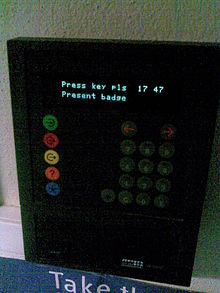
.JPG)
Contactless magnetic time clock card
Software based time and attendance systems are similar to paper-based systems, but they rely on computers and check-in terminals. They are backed up with software that can be integrated with the human resources department and in some cases payroll software. These types of systems are becoming more popular but due to high initial costs they are usually only adopted by large business of over 30 employees. Despite this they can save a business a lot of money every year by cutting down errors and reducing administration time.
Mobile time tracking
With the mass market proliferation of mobile devices (smart phones, handheld devices), new types of self-calculating time tracking systems have been invented which allow a mobile workforce – such as painting companies or construction companies - to track employees 'on' and 'off' hours. This is generally accomplished through either a mobile application, or an IVR based phone call in system. Using a mobile device allows enterprises to better validate that their employees or suppliers are physically 'clocking in' at a specific location using the GPS functionality of a mobile phone for extra validation.Biometrics
Biometric time clocks are a feature of more advanced time and attendance
systems. Rather than using a key, code or chip to identify the user,
they rely on a unique attribute of the user, such as a hand print,
finger print, finger vein, palm vein, facial recognition, iris or
retina. The user will have their attribute scanned into the system.
Biometric readers are often used in conjunction with an access control
system, granting the user access to a building, and at the same time
clocking them in recording the time and date. These systems also attempt
to cut down on fraud such as "buddy clocking." When combined with an
access control system they can help prevent other types of fraud such as
'ghost employees', where additional identities are added to payroll but
don't exist.
A clock is a device that tells the time. Some clocks can give the date as well as the time and a few give other information. There are different types of clocks. A watch is a type of clock that is small and can be carried. Watches are usually worn on a person's wrist. At one time, watches were commonly kept in the person's pocket.

ANALOG CLOCK
Keeping time
Clocks use different ways to measure time. Clocks need some sort of steady beat or motion to track the change in time. Ancient water clocks worked by the steady movement of water from a container with a hole in the bottom to another container without a hole. Other clocks use pendulums, springs and gears to track the change in time correctly.Digital clocks work by measuring the vibrations of quartz crystals when charged with electricity. The vibration frequency of the crystal does not change.
Atomic clocks use the electromagnetic waves absorbed and emitted by atoms such as caesium to measure time. They are the most precise clocks in the world.
Clock displays
There are many types of clocks and watches. The two most common types of displays on clocks are "analog" and "digital" .Analog clocks
Analog clocks use angles to tell time. They have hands that rotate around the clock's face. The position of the hands shows the time. The face of the clock is a flat disk. It will often have the numbers one through twelve on the face to make it easier to read. Analog clocks commonly have two or three hands. If it has two, there is a large hand or minute hand and a smaller hand, the hour hand. Clocks with three hands also have a second hand. This hand is usually about as long as the minute hand, but much thinner.Each hand shows the time it is named for and moves around the face of the clock one complete rotation for each movement to the next larger hand. For example, the second hand moves around the face of the clock in 60 seconds. It moves once each second. When it moves all the way around the clock, the minute hand moves forward one space. When the minute hand moves all the way around the face of the clock (which takes 60 minutes), the hour hand moves forward one section. The second and minute hands take 60 movements to move all around the face of the clock, the hour hand only needs 12 movements to do the same.
Digital clocks

A radio controlled digital clock
Sounds
There are also clocks that use sound, usually along with a dial or some other means, to show the time. The sound could be as simple as a bell or so complex that it sounds the same as a person. Many clocks that do this are old and are driven by springs or weights rather than batteries or other forms of electric power. Some special clocks are often used by people who are blind or cannot see well enough to read an analog or digital clock. They can also be used by people with mental problems that cause them to be unable to read other clocks.
Hourglass in wooden stand
A lot about clocks
There are many different types of clocks and watches. They are different in what they are used for, what they can do or how they are made. Examples include:- A wristwatch is worn on the wrist. It is held in place by two straps connected to the watch and then wrapped around the wrist and connected to each other.
- A pocket watch is kept in a pocket. It usually has a small chain which is connected to the person's clothing. This help stops the watch from being lost.
- A Sundial is an old form of a clock which uses the Sun to tell time.
- An alarm clock is a clock that makes a sound (often a buzzing or a bell-like sound) or plays music at a certain time. It is used by people to wake up from sleep at a time they choose.
- A grandfather clock is a tall clock that stands on a floor. It uses a pendulum to tell time.
- A Cuckoo clock is a pendulum based clock which makes a sound each hour on the hour. They often also have a small door. When the clock makes the sound, the door opens and a small toy bird or other item usually comes out of the door.
- An hourglass, also known as a sandglass or sand timer, uses sand trickling slowly to measure time.
Digital clock
A digital clock is a type of clock that displays the time digitally (i.e. in numerals or other symbols), as opposed to an analog clock, where the time is indicated by the positions of rotating hands.
Digital clocks are often associated with electronic drives, but the "digital" description refers only to the display, not to the drive mechanism. (Both analog and digital clocks can be driven either mechanically or electronically, but "clockwork" mechanisms with digital displays are rare.)

The first digital pocket watch was the invention of Austrian engineer Josef Pallweber who created his "jump-hour" mechanism in 1883. Instead of a conventional dial, the jump-hour featured two windows in an enamel dial, through which the hours and minutes are visible on rotating discs. The second hand remained conventional. By 1885 Pallweber mechanism was already on the market in pocket watches by Cortébert and IWC; arguably contributing to the subsequent rise and commercial success of IWC. The principles of Pallweber jump-hour movement had appeared in wristwatches by the 1920s (Cortébert) and are still used today (Chronoswiss Digiteur). While the original inventor didn't have a watch brand at the time, his name has since been resurrected by a newly established watch manufacturer.
Plato clocks used a similar idea but a different layout. These spring-wound pieces consisted of a glass cylinder with a column inside, affixed to which were small digital cards with numbers printed on them, which flipped as time passed. The Plato clocks were introduced at the St. Louis World Fair in 1904, produced by Ansonia Clock Company. Eugene Fitch of New York patented the clock design in 1903.13 years earlier Josef Pallweber had patented the same invention using digital cards (different from his 1885 patent using moving disks) in Germany (DRP No. 54093).The German factory Aktiengesellschaft für Uhrenfabrikation Lenzkirch made such digital clocks in 1893 and 1894.
The earliest patent for a digital alarm clock was registered by D.E Protzmann and others on October 23, 1956, in the United States. Protzmann and his associates also patented another digital clock in 1970, which was said to use a minimal amount of moving parts. Two side-plates held digital numerals between them, while an electric motor and cam gear outside controlled movement.
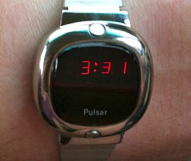
In 1970, the first digital wristwatch with an LED display was mass-produced. Called the Pulsar, and produced by the Hamilton Watch Company, this watch was hinted at two years prior when the same company created a prototype digital watch for Kubrick's 2001: A Space Odyssey.Throughout the 1970s, despite the initial hefty cost of digital watches, the popularity of said devices steadily rose.
Construction
Digital clocks typically use the 50 or 60 hertz oscillation of AC power or a 32,768 hertz crystal oscillator as in a quartz clock to keep time. Most digital clocks display the hour of the day in 24-hour format; in the United States and a few other countries, a commonly-used hour sequence option is 12-hour format (with some indication of AM or PM). Some timepieces, such as many digital watches, can be switched between 12-hour and 24-hour modes. Emulations of analog-style faces often use an LCD screen, and these are also sometimes described as "digital".Displays

A digital clock's display changing numbers
Setting
If people find difficulty in setting the time in some designs of digital clocks in electronic devices where the clock is not a critical function, they may not be set at all, displaying the default after powered on, 00:00 or 12:00.Because they run on electricity, digital clocks often need to be reset whenever the power is cut off, even for a very brief period of time. This is a particular problem with alarm clocks that have no "battery" backup, because a power outage during the night usually prevents the clock from triggering the alarm in the morning.
To reduce the problem, many devices designed to operate on household electricity incorporate a battery backup to maintain the time during power outages and during times of disconnection from the power supply. More recently, some devices incorporate a method for automatically setting the time, such as using a broadcast radio time signal from an atomic clock, getting the time from an existing satellite television or computer connection, or by being set at the factory and then maintaining the time from then on with a quartz movement powered by an internal rechargeable battery. Commercial digital clocks are typically more reliable than consumer clocks. Multi-decade backup batteries can be used to maintain time during power loss.
 An LCD battery-operated clock without alarm
 A premium digital clock radio with digital tuning
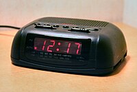 A basic digital clock radio with analog tuning


Uses of digital clocks

This digital clock has been attached to an oven.

This digital clock reacts to temperature.
Watch
A watch is a timepiece intended to be carried or worn by a person. It is designed to keep working despite the motions caused by the person's activities. A wristwatch is designed to be worn around the wrist, attached by a watch strap or other type of bracelet. A pocket watch is designed for a person to carry in a pocket. The study of timekeeping is known as horology.
Watches progressed in the 17th century from spring-powered clocks, which appeared as early as the 14th century. During most of its history the watch was a mechanical device, driven by clockwork, powered by winding a mainspring, and keeping time with an oscillating balance wheel.
n general, modern watches often display the day, date, month and year. For mechanical watches, various extra features called "complications", such as moon-phase displays and the different types of tourbillon, are sometimes included.Most electronic quartz watches, on the other hand, include time-related features such as timers, chronographs and alarm functions. Furthermore, some modern smartwatches even incorporate calculators, GPS and Bluetooth technology or have heart-rate monitoring capabilities, and some of them use radio clock technology to regularly correct the time.
Electronic movements, also known as quartz movements, have few or no moving parts, except a quartz crystal which is made to vibrate by the piezoelectric effect. A varying electric voltage is applied to the crystal, which responds by changing its shape so, in combination with some electronic components, it functions as an oscillator. It resonates at a specific highly stable frequency, which is used to accurately pace a timekeeping mechanism. Most quartz movements are primarily electronic but are geared to drive mechanical hands on the face of the watch to provide a traditional analog display of the time, a feature most consumers still prefer.
Watch batteries (strictly speaking cells, as a battery is composed of multiple cells) are specially designed for their purpose. They are very small and provide tiny amounts of power continuously for very long periods (several years or more). In most cases, replacing the battery requires a trip to a watch-repair shop or watch dealer; this is especially true for watches that are water-resistant, as special tools and procedures are required for the watch to remain water-resistant after battery replacement. Silver-oxide and lithium batteries are popular today; mercury batteries, formerly quite common, are no longer used, for environmental reasons. Cheap batteries may be alkaline, of the same size as silver-oxide cells but providing shorter life. Rechargeable batteries are used in some solar-powered watches.
Some electronic watches are powered by the movement of the wearer. For instance, Seiko's kinetic-powered quartz watches use the motion of the wearer's arm: turning a rotating weight which causes a tiny generator to supply power to charge a rechargeable battery that runs the watch. The concept is similar to that of self-winding spring movements, except that electrical power is generated instead of mechanical spring tension.
Solar powered watches are powered by light. A photovoltaic cell on the face (dial) of the watch converts light to electricity, which is used to charge a rechargeable battery or capacitor. The movement of the watch draws its power from the rechargeable battery or capacitor. As long as the watch is regularly exposed to fairly strong light (such as sunlight), it never needs a battery replacement. Some models need only a few minutes of sunlight to provide weeks of energy (as in the Citizen Eco-Drive). Some of the early solar watches of the 1970s had innovative and unique designs to accommodate the array of solar cells needed to power them (Synchronar, Nepro, Sicura and some models by Cristalonic, Alba, Seiko, and Citizen). As the decades progressed and the efficiency of the solar cells increased while the power requirements of the movement and display decreased, solar watches began to be designed to look like other conventional watche
Display
Analog


Casio AE12 LCA (liquid-crystal-analog) watch
Analog display of the time is nearly universal in watches sold as jewelry or collectibles, and in these watches, the range of different styles of hands, numbers, and other aspects of the analog dial is very broad. In watches sold for timekeeping, analog display remains very popular, as many people find it easier to read than digital display; but in timekeeping watches the emphasis is on clarity and accurate reading of the time under all conditions (clearly marked digits, easily visible hands, large watch faces, etc.). They are specifically designed for the left wrist with the stem (the knob used for changing the time) on the right side of the watch; this makes it easy to change the time without removing the watch from the wrist. This is the case if one is right-handed and the watch is worn on the left wrist (as is traditionally done). If one is left-handed and wears the watch on the right wrist, one has to remove the watch from the wrist to reset the time or to wind the watch.
Analog watches, as well as clocks, are often marketed showing a display time of approximately 1:50 or 10:10. This creates a visually pleasing smile-like face on the upper half of the watch, in addition to enclosing the manufacturer's name. Digital displays often show a time of 12:08, where the increase in the number of active segments or pixels gives a positive feeling.
Digital
A digital display shows the time as a number, e.g., 12:08 instead of a shorthand pointing towards the number 12 and a long hand 8/60 of the way around the dial. The digits are usually shown as a seven-segment display.The first digital mechanical pocket watches appeared in the late 19th century. In the 1920s, the first digital mechanical wristwatches appeared.
The first digital electronic watch, a Pulsar LED prototype in 1970, was developed jointly by Hamilton Watch Company and Electro-Data, founded by George H. Thiess.John Bergey, the head of Hamilton's Pulsar division, said that he was inspired to make a digital timepiece by the then-futuristic digital clock that Hamilton themselves made for the 1968 science fiction film 2001: A Space Odyssey. On 4 April 1972, the Pulsar was finally ready, made in 18-carat gold and sold for $2,100. It had a red light-emitting diode (LED) display.
Digital LED watches were very expensive and out of reach to the common consumer until 1975, when Texas Instruments started to mass-produce LED watches inside a plastic case. These watches, which first retailed for only $20, reduced to $10 in 1976, saw Pulsar lose $6 million and the Pulsar brand sold to Seiko.
An early LED watch that was rather problematic was The Black Watch made and sold by British company Sinclair Radionics in 1975. This was only sold for a few years, as production problems and returned (faulty) product forced the company to cease production.
Most watches with LED displays required that the user press a button to see the time displayed for a few seconds because LEDs used so much power that they could not be kept operating continuously. Usually, the LED display color would be red. Watches with LED displays were popular for a few years, but soon the LED displays were superseded by liquid crystal displays (LCDs), which used less battery power and were much more convenient in use, with the display always visible and no need to push a button before seeing the time. Only in darkness would a button need to be pressed to light the display with a tiny light bulb, later illuminating LEDs.
The first LCD watch with a six-digit LCD was the 1973 Seiko 06LC, although various forms of early LCD watches with a four-digit display were marketed as early as 1972 including the 1972 Gruen Teletime LCD Watch, and the Cox Electronic Systems Quarza. In Switzerland, Ebauches Electronic SA presented a prototype eight-digit LCD wristwatch showing time and date at the MUBA Fair, Basle, in March 1973, using a Twisted nematic LCD manufactured by Brown, Boveri & Cie, Switzerland, which became the supplier of LCDs to Casio for the CASIOTRON watch in 1974.
A problem with Liquid Crystal Displays is that they use polarized light. If, for example, the user is wearing polarized sunglasses, the watch may be difficult to read because the plane of polarization of the display is roughly perpendicular to that of the glasses.] If the light that illuminates the display is polarized, for example if it comes from a blue sky, the display may be difficult or impossible to read.
From the 1980s onward, digital watch technology vastly improved. In 1982 Seiko produced the Seiko TV Watch that had a television screen built-in,and Casio produced a digital watch with a thermometer as well as another that could translate 1,500 Japanese words into English. In 1985, Casio produced the CFX-400 scientific calculator watch. In 1987 Casio produced a watch that could dial telephone numbers and Citizen revealed one that would react to voice. In 1995 Timex released a watch which allowed the wearer to download and store data from a computer to their wrist. Some watches, such as the Timex Datalink USB, feature dot matrix displays. Since their apex during the late 1980s to mid-1990s high technology fad, digital watches have mostly become simpler, less expensive timepieces with little variety between models.

___________________________________________________________________________________
Astrology in time and energy
ASTROLOGY AND THE ENERGIES
To these two energies, a
third group of energies must be added, and these are the basis of much of our
astrological research. They emanate from the twelve constellations which form
our solar zodiac. Their effect is infinite and the permutations of these three
groups of energies lead to the infinite complication which we find in nature.
The claims of the astrologers as to the reality of the energies playing upon
the human organism can be seen to be true; their claims as to their capacity to
interpret are for the most part unfounded. So little is really known by the
highest intelligence on the planet; for, forget not, that the adepts utilise
primarily the intuition. These energies leave their mark upon every form in
every kingdom in nature, acting as a retrograding or a stimulating force. They
carry one type of energy on to a fuller expression of the quality of any form,
or hold another back from a developed manifestation.
Each planet
represents a different part of life, a different energy. In psychology
terms, they are considered your “needs” or “drives”. ... The personal planets are the Sun, the Moon, Mercury, Venus, and Mars. They are called fast-moving planets because they travel through the entire zodiac quickly.
It is not opportune here to
outline the nature of true astrology. That astrology is a science, and a
coming science, is true. That astrology in its highest aspect and its true
interpretation will enable man eventually to focus his understanding and to
function rightly is equally true. That in the revelations that astrology will
make in time to come will be found the secret of the true coordination between
soul and form is also correct. But that astrology is not yet to be
found. Too much is overlooked and too little known to make astrology the exact
science that many claim it is. The claim
will be fulfilled at some future date, but the time is not yet.
Certain factors which
astrologers should bear in mind, and certain conditions they are only too apt
to forget, may however be briefly noted. For the sake of clear understanding
we will simply tabulate a number of statements which should be studied with
care by the average
investigator in this field. I cannot here write a treatise on the energies
with which astrology should deal, sorely as such a treatise is needed.
Astrologers concern
themselves primarily with three types of energy:
a. The energy of the constellation in which the Sun is
posited at the time of birth.
b. The rising sign to which the man should respond.
c. The moon which governs his form aspect, and
particularly the physical form.
The energy of the particular
constellation or sign in which a man is born is more deeply significant than
has ever yet been suggested. It embodies or indicates his present problem,
sets the pace or tempo of his life, and is related to the quality of his
personality. It governs, if I may so express it, the rajasic or activity
aspect of his life during incarnation.
The ascendant or rising sign
indicates the line along which his energy as a whole can flow if he is to
fulfill the purpose of any incarnation. This, of course, if rightly handled.
It holds the secret of his future, and in its symbolism and understanding he
can find the clue to his life problem and an indication of what he can be and
achieve. It presents to him the type of force which will enable him to
succeed. This, when duly consummated, might be regarded as producing the
sattvic, or harmony aspect of his life, for when it plays its part and is
utilised, it produces harmony with the will of the soul during any particular
incarnation.
In the moon influence, we
have indicated the native's past. It summarises the limitations and handicaps
under which he must work, and therefore might be regarded as embodying the
tamasic aspect of matter, or that which "holds back" and which—if
permitted to influence unduly—will produce inertia. In the body with which man is
equipped lies hid the secret of past experience, and every lunar form through
which we have to arrive at due expression is in itself the product or synthesis
of all the past. Let me see if I can put the present truth about astrology in
such simple guise that they who know naught of this intricate science may
understand.
The birth month indicates the
day of opportunity. The door stands open. The particular month in which a
soul comes into incarnation is indicated to that soul by the month in which it
passed out of incarnation in a previous life cycle. If it, for instance, died
in the month governed by the sign Leo, it will return into incarnation in the
same sign, picking up the thread of experience where it left it, and starting
with the same type of energy and the peculiar equipment with which it passed
away from earth life, plus the gain of thought and conscious onlooking. The
quality of the energy and the nature of the forces to be manipulated during
life are indicated to the soul in this way.
The rising sign, embodying
another type of energy, should wax in strength during the incarnation, for it
indicates the nature of the soul force that the incarnated son of God is
seeking to wield through the medium of a particular personality, possessing
certain characteristics.
The influence of the moon is
primarily physical. The prison of the soul is thus indicated. The handicaps
to be met are thus secured; the type of body or of bodies through which the
force of the native's sign and the quality of the energy which will bring him
to his goal are thus defined. Through the medium of the lunar lords and what
they have given him as the result of past experience down the ages must he
express himself upon the physical plane.
Owing to the precession of
the equinoxes, a situation is brought about in which a fourth type of force
makes itself felt. The sun is, in reality, many degrees away
in the great round of the heavens from where it is stated to be, as far as the
greater zodiac is concerned. This is, of course, from the standpoint of time.
As the sweep of the sun through a constellation covers a period of
approximately two thousand two hundred years, the shift in the course of the
centuries is very slight, so slight that little difference would be noted in
the casting of the planetary horoscope. In the casting of the horoscope of a
solar system it would be of vital importance, but this is so far beyond the
capacity of the wisest astrologer on our planet that discussion is immaterial.
In casting the horoscope of a
human being who is born in a particular month, however, it should be borne in
mind (which it seldom is) that now the month and the sign do not coincide at
all. The sun is really not in Leo, for instance, during the month of August.
The correct interpretation therefore of a chart is largely psychometrical and
dependent upon the thought-form of the constellation which has been built up
for ages by the astrologers. Energy follows thought. For thousands of years
certain types of energy and their consequent qualifying effects on substance
and form have been considered to be thus and so. Therefore, thus they are,
except in the case of the highly evolved, of the true aspirant who has oriented
himself, and is thus escaping from the wheel of existence and beginning to
govern his stars, and so is no longer under their rule and domination.
Astrology now deals primarily
with the personality for whom the horoscope may be cast and with the events of
the personality life. When, through meditation and service, plus the
discipline of the lunar bodies, a man comes consciously and definitely under
his soul ray, then he comes as definitely under the influence of one or other
of the seven solar systems, as they focus their energy through one or other of
the constellations and subsequently one or other of the seven sacred
planets. Eventually, there will be twelve sacred planets, corresponding to the
twelve constellations, but the time is not yet. Our solar system, as you know,
is one of seven. When a man has arrived at this point in evolution, birth
months, mundane astrology, and the influences which play upon the form aspect
become of less and less importance. This circle of solar systems affects
paramountly the soul and it becomes the focal point of spiritual energies.
This is the problem of the soul on its own plane,—responsiveness to these types
of energy, and, of them, the personality is totally unaware.
The signs which fall
therefore into the four categories of earth, water, fire and air, concern
primarily the man who lives below the diaphragm, and who utilises the lower
four centres:—the centre at the base of the spine, the sacral centre, the solar
plexus and the spleen. The inner group of seven major or systemic energies
produce their effect upon the man who is living above the diaphragm, and work
through the seven representative centres in the head. Four of them focus
through the throat centre, the heart centre, the ajna and head centres. Three
are held latent in the region of the head centres (the thousand petalled lotus)
and only enter into functioning activity after the third initiation. It will
be evident therefore how complicated from the standpoint of the horoscope (as
well as of the individual problem) is this meeting of the energies of two types
of constellations in the case of the man who is neither purely human nor purely
spiritual. The ordinary horoscope is negated. The horoscope is not possible
as yet of delineation. The only horoscope, which is basically and almost
infallibly correct is that of the entirely low grade human being who lives
entirely below the diaphragm and is governed by his animal nature alone.
Astrologers must remember
also that there are several undiscovered planets which are producing pulls and
shifts and focussing streams of energy upon our earth which tend to complicate
the problem still further. Pluto is one of them, and having now emerged into
manifestation (or rather into recognition) to it will be assigned all the
unexplained conditions. Pluto will be made the scapegoat for faulty astrology
for a long time to come. This chart failed to work and be true because Pluto
must be influential in it and we know little about Pluto. So the story will
run. Yet Pluto has always been revolving around our sun and producing its
effects. It governs however the death or cessation of old ideas and emotions,
and its influence is therefore largely cerebral and in that you have the clue
to its late discovery. Mankind is only on the verge of becoming mental. Its
effects are felt first in the mental body. The names of the planets are not
the result of arbitrary choice but the planets name themselves.
Astrologers will eventually
find it necessary to cast three horoscopes or three charts:—one purely physical
dealing with the body of nature; one primarily emotional, and dealing with the
quality of the personality and with its sensitivity, or state of awareness;
the third will be the chart of the mental impulses and conditions. It will be
found that these three charts will take certain geometrical lines, the lines of
energies will form patterns. These three charts, superimposed one upon the
other, will give the personality diagram, the individual life pattern. Amazing
symbolic charts and lineal forms will be found to emerge when this is done, and
the "geometry of the individual" will grow out of this, for it will
be found that each line will function in relation to another line, and the
trends of the life energies will become apparent. Eventually, even in this
department of knowledge, "the star will shine
forth." This will constitute a new branch of psychology and its
true exponent for our age will duly be found. I but indicate the lines
of the future astrology in order to safeguard the present.
One thing astrologers need at
this time to do and that is to make due allowance for this transition period
out of Pisces into Aquarius. This is seldom done, but it is evident that the
tremendous turmoil incident to these transitions affects the individual chart,
and frequently offsets individual destiny or karma. People are submerged in
planetary and racial destinies, and their own tiny affairs are offset almost
entirely and sometimes completely negated. It is not possible to cast the
horoscope of the planet, and those who propose to do so are deceiving
themselves and others. The horoscope of the fourth kingdom in nature, of
humanity, will eventually be cast, but it will be done by initiates, and there
are no initiate astrologers working on the physical plane at this time. One
hint here I give.
The Sun was in Sagittarius
when the first human tendencies struggled to the fore. The stage of animal man
was completed and when Sagittarius was dominant (from our planetary
standpoint—I am using words with care) the great event of individualisation
took place. But the brain of the then human being failed to register what had
happened. In the words of the Old Commentary:
"The sons of God shot
forth like arrows from the bow. The forms received the impulse and lo! a God
was born. The tiny babe knew not the great event."
This took place twenty-one
million years ago. Cycles passed and when at a later date the sun was in Leo
(approximately eighteen million years ago) the first instances of coordination
between brain and mind took place and the human being was definitely
self-conscious. He registered his individuality. The figures for the first . date
(though exactness is not possible in a system of mutation such as ours) are
21,688,345 years ago. These figures are useless at this time for they can
neither be proved correct nor incorrect. Later investigation will prove their
usefulness, when the nature of time is better understood. Sagittarius governs
human evolution, for it symbolises progress towards a conscious goal. Leo
governs the human consciousness in the human kingdom for the energy pouring
through it enables man to say "I am".
It might be of value if I
here attempted a translation necessarily inadequate, of the key word of each
sign. These fall into two categories as far as humanity is concerned. There
is the key word for the form aspect and the keyword for the soul aspect. In
the first case, the word is expressed; in the second it is consciously spoken
by the soul. Translated into modern terms much is lost, but the underlying
thought which directs the work of the emanating energies is of value. For our
world period they are as follows:
For the aspirant who
progresses from Aries to Pisces and has therefore re-oriented himself we have:
Aries
|
I come forth, and from the
plane of mind I rule.
|
Taurus
|
I see, and when the eye is
opened, all is illumined.
|
Gemini
|
I recognise my other self
and in the waning of that self I grow and glow.
|
Cancer
|
I build a lighted house and
therein dwell.
|
Leo
|
I am That and That am I.
|
Virgo
|
I am the Mother and the
Child, I God, I matter am.
|
Libra
|
I choose the Way that leads
between the two great lines of force.
|
Scorpio
|
Warrior I am, and from the
battle I emerge triumphant.
|
Sagittarius
|
I see the goal. I reach
the goal and see another.
|
Capricorn
|
Lost am I in light supernal
and on that light I turn my back.
|
Aquarius
|
Water of life am I, poured
forth for thirsty men.
|
Pisces
|
I leave the Father's home
and turning back, I save.
|
rom the standpoint of the form, the life proceeds in a reverse direction, and the work of nature is seen under the following words:
Pisces
|
And the Word said: Go
forth into matter.
|
Aquarius
|
And the Word said: Let
desire in form be ruler.
|
Capricorn
|
And the Word said: Let
ambition rule and the door stand wide.
|
Sagittarius
|
And the Word said: Let
food be sought.
|
Scorpio
|
And the Word said: Let
Maya flourish and deception rule.
|
Libra
|
And the Word said: Let
choice be made.
|
Virgo
|
And the Word said: Let
matter reign.
|
Leo
|
And the Word said: Let
other forms exist, I rule.
|
Cancer
|
And the Word said: Let
isolation be the rule and yet the crowd exists.
|
Gemini
|
And the Word said: Let
instability do its work.
|
Taurus
|
And the Word said: Let
struggle be undismayed.
|
Aries
|
And the Word said: Let
form again be sought.
|
It will be noted that all
these ideas concern the work of energy in some form or another and in the last
grouping with the work of the so-called unregenerate selfish individual, full
of desire for satisfaction. The group of mantric words used by the aspirant in
the power of his own soul, are positive.
It seems needless to deal
further with the various types of force and we shall now turn our attention to
Rule XI.

___________________________________________________________________________________
STAR_C
A star is an astronomical object consisting of a luminous spheroid of plasma held together by its own gravity. The nearest star to Earth is the Sun. Many other stars are visible to the naked eye from Earth during the night, appearing as a multitude of fixed luminous points in the sky due to their immense distance from Earth. Historically, the most prominent stars were grouped into constellations and asterisms, the brightest of which gained proper names. Astronomers have assembled star catalogues that identify the known stars and provide standardized stellar designations. However, most of the estimated 300 sextillion (3×10²³) stars in the observable universe are invisible to the naked eye from Earth, including all stars outside our galaxy, the Milky Way.For at least a portion of its life, a star shines due to thermonuclear fusion of hydrogen into helium in its core, releasing energy that traverses the star's interior and then radiates into outer space. Almost all naturally occurring elements heavier than helium are created by stellar nucleosynthesis during the star's lifetime, and for some stars by supernova nucleosynthesis when it explodes. Near the end of its life, a star can also contain degenerate matter. Astronomers can determine the mass, age, metallicity (chemical composition), and many other properties of a star by observing its motion through space, its luminosity, and spectrum respectively. The total mass of a star is the main factor that determines its evolution and eventual fate. Other characteristics of a star, including diameter and temperature, change over its life, while the star's environment affects its rotation and movement. A plot of the temperature of many stars against their luminosities produces a plot known as a Hertzsprung–Russell diagram (H–R diagram). Plotting a particular star on that diagram allows the age and evolutionary state of that star to be determined.
A star's life begins with the gravitational collapse of a gaseous nebula of material composed primarily of hydrogen, along with helium and trace amounts of heavier elements. When the stellar core is sufficiently dense, hydrogen becomes steadily converted into helium through nuclear fusion, releasing energy in the process. The remainder of the star's interior carries energy away from the core through a combination of radiative and convective heat transfer processes. The star's internal pressure prevents it from collapsing further under its own gravity. A star with mass greater than 0.4 times the Sun's will expand to become a red giant when the hydrogen fuel in its core is exhausted. In some cases, it will fuse heavier elements at the core or in shells around the core. As the star expands it throws a part of its mass, enriched with those heavier elements, into the interstellar environment, to be recycled later as new stars. Meanwhile, the core becomes a stellar remnant: a white dwarf, a neutron star, or, if it is sufficiently massive, a black hole.
Binary and multi-star systems consist of two or more stars that are gravitationally bound and generally move around each other in stable orbits. When two such stars have a relatively close orbit, their gravitational interaction can have a significant impact on their evolution. Stars can form part of a much larger gravitationally bound structure, such as a star cluster or a galaxy.

Designations
The concept of a constellation was known to exist during the Babylonian period. Ancient sky watchers imagined that prominent arrangements of stars formed patterns, and they associated these with particular aspects of nature or their myths. Twelve of these formations lay along the band of the ecliptic and these became the basis of astrology. Many of the more prominent individual stars were also given names, particularly with Arabic or Latin designations.As well as certain constellations and the Sun itself, individual stars have their own myths. To the Ancient Greeks, some "stars", known as planets (Greek πλανήτης (planētēs), meaning "wanderer"), represented various important deities, from which the names of the planets Mercury, Venus, Mars, Jupiter and Saturn were taken.] (Uranus and Neptune were also Greek and Roman gods, but neither planet was known in Antiquity because of their low brightness. Their names were assigned by later astronomers.)
Circa 1600, the names of the constellations were used to name the stars in the corresponding regions of the sky. The German astronomer Johann Bayer created a series of star maps and applied Greek letters as designations to the stars in each constellation. Later a numbering system based on the star's right ascension was invented and added to John Flamsteed's star catalogue in his book "Historia coelestis Britannica" (the 1712 edition), whereby this numbering system came to be called Flamsteed designation or Flamsteed numbering.
The only internationally recognized authority for naming celestial bodies is the International Astronomical Union (IAU). The International Astronomical Union maintains the Working Group on Star Names (WGSN) which catalogs and standardizes proper names for stars. A number of private companies sell names of stars, which the British Library calls an unregulated commercial enterprise. The IAU has disassociated itself from this commercial practice, and these names are neither recognized by the IAU, professional astronomers, nor the amateur astronomy community. One such star-naming company is the International Star Registry, which, during the 1980s, was accused of deceptive practice for making it appear that the assigned name was official. This now-discontinued ISR practice was informally labeled a scam and a fraud, and the New York City Department of Consumer and Worker Protection issued a violation against ISR for engaging in a deceptive trade practice
Formation and evolution

Stellar evolution of low-mass (left cycle) and high-mass (right cycle) stars, with examples in italics
_________________________________________________________________________________
Gen. Mac Tech Zone EINSTEIN and STAR_C
Tidak ada komentar:
Posting Komentar