
human stem cells is a place where the storage of human genetic memory where genes or human codes are made sequentially that form a tangible development of an organ of living things called humans, this human stem cell code can be taken during one week of fertilization between sperm cells and cells eggs and their shape are almost identical for all stem cells of living creatures other than humans. when humans were created by the Father in heaven, the code of the genetic code was revealed until now where humans can manifest according to their original form, namely when God formed the first human, at that time God formed from embryonic cells from the embryo composition from the existence of the new earth which he created itself in the form of similarities between the horizon, soil, dust and water as the initial embryo of the formation of the earth. God said that you were created in the same image and likened to me, and so the Lord Jesus always made a parable in the likeness and like, we were created in the same image and in the same way as our creator, and that means our mother cell was similar and similar. in this era we can call God's past copy so and if copy paste wants to be perfect with the creator of course we must continue to know him, so that we will be equal and perfect of course for the grace and affection of the creator, God himself. in the detection and processing of human embryos in today's era many use modern technology in the form of sophisticated electronic engineering techniques that are artificial intelligence, which is the second derivative of human thinking. if we call it in the complex electronic language that is the 2nd differential, we are the 1st differential from God who is the Father in heaven if we hear the diffraction means there is a matter of development time in the usual calculations in electronics called Timer For Up / down Counter or we are Real Word (up counter) and Retro (down Counter).
Love in Second Save of Light
( Gen . Mac Tech Zone Point Virtual Matrix )
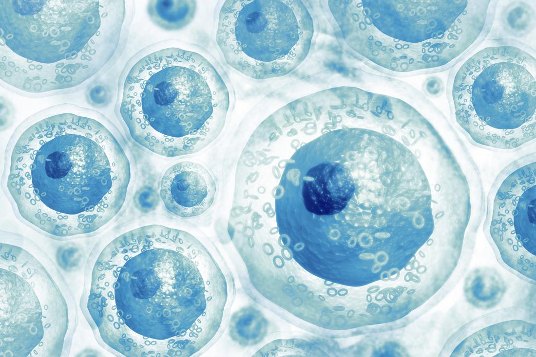
X O 11 stem cells
Scientists and doctors are interested in stem cells as they help to explain how some functions of the body work, and how they sometimes go wrong.
Sources of stem cells
Stem cells originate from two main sources: adult body tissues and embryos. Scientists are also working on ways to develop stem cells from other cells, using genetic "reprogramming" techniques.
Adult stem cells
Also called tissue-specific or somatic stem cells, adult stem cells exist throughout the body from the time an embryo develops.
The cells are in a non-specific state, but they are more specialized than embryonic stem cells. They remain in this state until the body needs them for a specific purpose, say, as skin or muscle cells.
Day-to-day living means the body is constantly renewing its tissues. In some parts of the body, such as the gut and bone marrow, stem cells regularly divide to produce new body tissues for maintenance and repair.
Stem cells are present inside different types of tissue. Scientists have found stem cells in tissues, including:
- the brain
- bone marrow
- blood and blood vessels
- skeletal muscles
- skin
- the liver
Adult stem cells can divide or self-renew indefinitely. This means they can generate various cell types from the originating organ or even regenerate the original organ, entirely.
This division and regeneration are how a skin wound heals, or how an organ such as the liver, for example, can repair itself after damage.
In the past, scientists believed adult stem cells could only differentiate based on their tissue of origin. However, some evidence now suggests that they can differentiate to become other cell types, as well.
Embryonic stem cells
From the very earliest stage of pregnancy, after the sperm fertilizes the egg, an embryo forms.Around 3–5 days after a sperm fertilizes an egg, the embryo takes the form of a blastocyst or ball of cells.
The blastocyst contains stem cells and will later implant in the womb. Embryonic stem cells come from a blastocyst that is 4–5 days old.
When scientists take stem cells from embryos, these are usually extra embryos that result from in vitro fertilization (IVF).
In IVF clinics, the doctors fertilize several eggs in a test tube, to ensure that at least one survives. They will then implant a limited number of eggs to start a pregnancy.
When a sperm fertilizes an egg, these cells combine to form a single cell called a zygote.
This single-celled zygote then starts to divide, forming 2, 4, 8, 16 cells, and so on. Now it is an embryo.
Soon, and before the embryo implants in the uterus, this mass of around 150–200 cells is the blastocyst. The blastocyst consists of two parts:
- an outer cell mass that becomes part of the placenta
- an inner cell mass that will develop into the human body
With the right stimulation, the cells can become blood cells, skin cells, and all the other cell types that a body needs.
In early pregnancy, the blastocyst stage continues for about 5 days before the embryo implants in the uterus, or womb. At this stage, stem cells begin to differentiate.
Embryonic stem cells can differentiate into more cell types than adult stem cells.
Mesenchymal stem cells (MSCs)
MSCs come from the connective tissue or stroma that surrounds the body's organs and other tissues.Scientists have used MSCs to create new body tissues, such as bone, cartilage, and fat cells. They may one day play a role in solving a wide range of health problems.
Induced pluripotent stem cells (iPS)
Scientists create these in a lab, using skin cells and other tissue-specific cells. These cells behave in a similar way to embryonic stem cells, so they could be useful for developing a range of therapies.However, more research and development is necessary.
To grow stem cells, scientists first extract samples from adult tissue or an embryo. They then place these cells in a controlled culture where they will divide and reproduce but not specialize further.
Stem cells that are dividing and reproducing in a controlled culture are called a stem-cell line.
Researchers manage and share stem-cell lines for different purposes. They can stimulate the stem cells to specialize in a particular way. This process is known as directed differentiation. it has been easier to grow large numbers of embryonic stem cells than adult stem cells. However, scientists are making progress with both cell types.

X O 110 110 Stem Cells and the study of Mathematics , Statistics and Physics
Human stem cells are at the forefront of modern molecular biology research due to their ability to give rise to any specialist human cell type, a property known as pluripotency. However, stem cells are notoriously hard to grow in culture. Here we are developing mathematical models of the stem cell behaviour, from single or a few cells up to colonies of thousands.
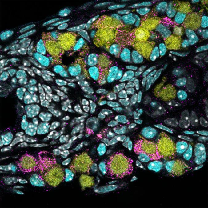
the last concept of "Dynamics of single human embryonic stem
cells and their pairs: a quantitative analysis" we
performed real-time microscope imaging of human embryonic stem cells and
analysed the kinematics of single and pairs of cells.
We find that the cells, and their pairs, typically move like an isotropic random walk with a characteristic speed. Here, we present a movie of the typical stem cell motion.
We find that the cells, and their pairs, typically move like an isotropic random walk with a characteristic speed. Here, we present a movie of the typical stem cell motion.

Ecological Networks

An ecological network is a representation of the interactions between species in an ecosystem, a familiar example of which is the food web. Recent advances in DNA sequencing techniques allow biologists to construct and describe such networks in unprecedented levels of detail.
we are interested in understanding the dynamics of species within complex ecological networks and predicting network responses to external perturbations. We must saving of Biology with real-world ecological data sets.
X O 110 110 110 Data set in electronic circuit electron , we call Counter and frequency
In digital logic and computing, a counter is a device which stores (and sometimes displays) the number of times a particular event or process has occurred, often in relationship to a clock signal. ... A counter circuit is usually constructed of a number of flip-flops connected in cascade.
Counter is a digital device and the output of the counter includes a predefined state based on the clock pulse applications. The output of the counter can be used to count the number of pulses. Generally, counters consist of a flip-flop ( memory ) arrangement which can be synchronous counter or asynchronous counter.
Types of Counters, Binary Ripple Counter, Ring Counter, BCD Counter, Decade counter, Up down Counter, Frequency Counter.
Up - Counter
Counter is a sequential circuit. A digital circuit which is used for a counting pulses is known counter. Counter is the widest application of flip-flops. It is a group of flip-flops with a clock signal applied.
The only difference is that for the up counter the output is taken at the non-inverting output ports of the flip-flops. Whereas, for the down counter the output is taken at the inverting output ports of the flip-flops.
Counters are used in digital electronics for counting purpose, they can count specific event happening in the circuit. For example, in UP counter a counter increases count for every rising edge of clock.
Counter means ;
1 : marked by or tending toward or in an opposite direction or effect. 2 : given to or marked by opposition, hostility, or antipathy. 3 : situated or lying opposite the counter side.
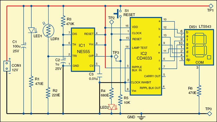
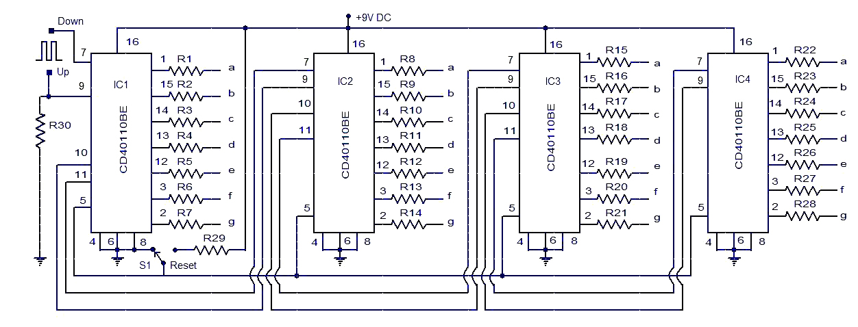
Circuit diagram of the electronic letterbox with letter-counting facility
Pulse Detecting Genetic Circuit
In digital logic and computing, a counter is a device which stores (and sometimes displays) the number of times a particular event or process has occurred, often in relationship to a clock signal. The most common type is a sequential digital logic circuit with an input line called the clock and multiple output lines. The values on the output lines represent a number in the binary or BCD number system. Each pulse applied to the clock input increments or decrements the number in the counter.
A counter circuit is usually constructed of a number of flip-flops connected in cascade. Counters are a very widely used component in digital circuits, and are manufactured as separate integrated circuits and also incorporated as parts of larger integrated circuits.
In electronics, counters can be implemented quite easily using register-type circuits such as the flip-flop, electronics is a complete language of communication and a wide variety of classified into:
- Asynchronous (ripple) counter – changing state bits are used as clocks to subsequent state flip-flops
- Synchronous counter – all state bits change under control of a single clock
- Decade counter – counts through ten states per stage
- Up/down counter – counts both up and down, under command of a control input
- Ring counter – formed by a shift register with feedback connection in a ring
- Johnson counter – a twisted ring counter
- Cascaded counter
- Modulus counter.
Occasionally there are advantages to using a counting sequence other than the natural binary sequence—such as the binary coded decimal counter, a linear-feedback shift register counter, or a Gray-code counter.
Counters are useful for digital clocks and timers, and in oven timers, VCR clocks, etc.
A robust cellular counter could enable synthetic biologists to design complex circuits with diverse behaviors. The existing synthetic-biological counters, responsive to the beginning of the pulse, are sensitive to the pulse duration. Here to present a pulse detecting circuit that responds only at the falling edge of a pulse–analogous to negative edge triggered electric circuits. As biological events do not follow precise timing, use of such a pulse detector would enable the design of robust asynchronous counters which can count the completion of events. This transcription-based pulse detecting circuit depends on the interaction of two co-expressed lamb doid phage-derived proteins: the first is unstable and inhibits the regulatory activity of the second, stable protein. At the end of the pulse the unstable inhibitor protein disappears from the cell and the second protein triggers the recording of the event completion. Using stochastic simulation we showed that the proposed design can detect the completion of the pulse irrespective to the pulse duration. In our simulation we also showed that fusing the pulse detector with a phage lambda memory element we can construct a counter which can be extended to count larger numbers. The design principle is a new control mechanism for synthetic biology which can be integrated in different circuits for identifying the completion of an event.

Synthetic biology borrows the basic principles from engineering and molecular biology, and applies these principles in designing, testing, validating and assembling genetic parts into larger systems . Over the past 15 years synthetic biology researchers have designed numerous synthetic genetic circuits and a trend of increasing circuit complexity seems likely . The design principles of electrical circuits have inspired and have been incorporated in the construction of many synthetic genetic circuits . Like in electrical circuits, memory is an essential functional unit in biological systems which records the received stimulus and directs the cell fate in alternate directions based on the logged experience. Consequently, a diverse design approach has been exercised in registering a biological event in a cell and probing the record at a later time .

A counter is another basic device that track events and is extensively used in building a wide range of complex electrical circuits. The existence of counting mechanism in wild organisms has been documented . With the help of a robust cellular counter, synthetic biologists could design novel control mechanisms and applications based on the occurrence of events. A few successful circuits have been constructed .
The design of a counter makes the use of memory and a single memory unit can work as a counter capable of counting a single event. Such a one-counter can be cascaded to count numbers larger than one but counting high numbers will be challenging because the number of orthogonal systems will increase linearly with the maximum number we want to count. One way to overcome this difficulty is to use set-reset memory devices ( Integral list point )

Another potential challenge in designing a robust biological counter is the ability to count at completion of the event. The existing designs of the counters are sensitive to the pulse duration–a brief pulse will be ignored and a lengthy pulse can cause the counter to count ahead .
This problem can be evaded if we can design a counter that advances the count at the end of the pulse, as is the common practice in electrical counter design . The essential component in such a design is a pulse detecting circuit that responses only at the falling edge of the pulse stimulus. Use of such a pulse detector will make the counter robust to pulse duration. The design of the robust genetic pulse detector using the lambda CI repressor protein . By preventing the dimerization of CI protein until the triggering pulse completes, we identify the end of the event and subsequently the dimerized CI protein will trigger the reporter circuit. In simulation we tested and characterized the pulse detecting device to identify the limit of its operation. We designed an extendable one-counter by coupling this pulse detecting circuit with a lambda switch based memory .
Using a detailed chemical modeling and stochastic simulation we show that the presented robust pulse detector works with practical biologically parameters and can be used in designing falling edge triggered genetic counter.
A new design control for pulse detection
In principle, it is possible to design an asynchronous counter using both negative edge triggering (NET) and positive edge triggering (PET). However, in electronics most of the asynchronous counters are designed using NET because it makes the linking to flip-flops easier which should change state when the previous bit changes from high to low. An additional advantage of designing counters with NET is that they count events irrespective of the event’s duration and frequency.
is analogous to synchronous counters found in digital systems, and counted correctly only in response to pulses of defined duration. In contrast, the design of the counter outlined in corresponds to asynchronous counters. A pulse detector circuit that triggers only at the falling edge of a pulse would facilitate the design of an asynchronous counter and can be used in designing many other genetic circuits. We have a pulse detector circuit that uses distinctive characteristics of the lambda CI repressor protein to explore design considerations for a transcription-based biological negative edge detector. The bacteriophage lambda has a complex set of interlocking regulatory mechanisms that it uses to maintain the lysogenic state and to transition to the lytic state .
In the lysogenic state the lambda genome is integrated in the chromosome of host cell and replicated with cell division. In response to a DNA-damage signal, the lambda-phage exits the stable lysogenic state and enters the lytic state in which the phage lyses the cell, producing many new phage particles.
One regulatory module in lambda genome, colloquially known as lambda switch, mediates this decision and consists of: cI and cro genes, two promoters (PRM and PR transcribing cI and cro respectively) and three operators (OR1, OR2, and OR3) in the OR region .
the three operators in the OR region enhance the cooperativity of the system with respect to cI and allow a hair-trigger response in switching from the CI-rich state to the Cro-rich state .
Both CI and Cro proteins bind to the three operators with different affinities and control the transcription of cI and cro genes. RNA polymerase can transcribe gene cro when both OR1 and OR2 are free; similarly gene cI is transcribed when OR3 is free. CI protein can enhance the transcription from PRM promoter when bound to OR2. A moderate level of CI protein is maintained by shutting down the PRM
promoter when CI level crosses a certain threshold. The double negative
feedback mechanism along with the positive feedback from CI controls
the expression of only one of the two genes (cI and cro) repressing the other and thereby allows the lambda phage maintaining its lysogenic state and switching to the lytic state . These features allowed Kotula et al.
to construct a memory element based on switching from the CI state to
the Cro state. These authors also noted that the Cro state was quite
stable, at least under the conditions tested. Thus, switching from the
Cro to the CI state could also be used to record events; this is the
approach used here.
One characteristic of CI and Cro proteins, important for our design, is that they bind to the OR
operator sites in their dimer and higher-order multimers only; monomers
have no activity. Therefore activation and repression of these PR and PRM
promoters could be controlled by preventing the dimer formation of CI
and Cro proteins. This is a key element of the genetic device we present
here. In their study on operator and non-operator DNA binding of lambda
repressor protein CI, Nelson and Sauer isolated a mutant of CI
repressor bearing a mutation in the DNA binding surface, Asn55Lys (N55K)
that eliminated the binding affinity of the CI-mutant to operator sites
but increased the affinity to non-specific DNA binding sites . We recently demonstrated that CI (N55K) acts as a dominant negative inhibitor of the CI protein itself , presumably by forming mixed dimers as has been observed for the tet and lac repressors .
This mutation should not affect the dimerization characteristics of the
protein. We refer to this protein as dominant-negative CI (CIDN)
which is used for blocking dimer formation of CI proteins. Inhibition
of the activity of a transcription factor by complexation with a
dominant negative partner has previously been found useful .
Another protein that can be used to block the activity of lambda CI
protein is the Antirepressor of P22, which appears to inactivate
numerous lambdoid phage repressors .
The architecture of the pulse detecting circuit, assumed to be hosted in E coli bacterium, is shown in Fig 1(A). We placed both the wild-type cI and cIDN under the control of a single inducible promoter. A degradation tag is added with cIDN to ensure quick degradation of the monomeric proteins. One obvious candidate for the inducible promoter could be the TetA promoter PTetA . A much stronger RBS (RBS1) is required for cIDN than the RBS (RBS2) for cI. Experimentally one would use a reporter such as the lacZ gene under the control of PRM promoter. Essentially, the system works as follows: when the PTetA is induced (during the pulse), CIDN and CI transcripts are produced. Because of the stronger RBS associated with CIDN, many more CIDN
molecules are present in the cell compared to CI molecules. Therefore,
almost all of the CI monomers will form heterodimers with CIDN, and there will be no CI2 to activate PRM promoter. After the induction period, because of the degradation tag CIDN molecules degrade quickly giving CI molecules a chance to form dimers and activate PRM promoter. Fig 1(B) explains the input output relationship for the pulse detecting circuit.

Schematic representation of the negative edge triggered pulse detecting circuit.
(a)
Components of the pulse detecting circuit. The central element is an
artificial operon in which a regulated promoter directs transcription of
high levels of an unstable inhibitor protein and lower levels of a
target transcriptional regulator. In the specific version shown here,
the tetracycline-regulated TetA promoter directs transcription of,
firstly, a dominant-negative mutant of the lambda cI gene with a degradation tag (green), and secondly an intact version of the cI gene (red). TetR, the tetracyline repressor (gray), blocks transcription of this unit and PRM (which is activated by intact CI protein) transcribing lacZ
(sky-blue) serves as an illustrative readout of circuit activity. (b)
Behavioral characteristics of the circuit in response to an inducing
pulse, with time proceeding downward. In the initial absence of the
inducer tetracycline, neither of the proteins is made and lacZ is OFF. Upon addition of tetracycline, both proteins are made and the CIDN protein inhibits the wild-type protein, so lacZ remains OFF. Upon removal of the inducer, the CIDN protein is rapidly degraded while the wild-type CI protein remains intact, and activates lacZ transcription.
stochastic simulation, we analyzed the pulse detecting circuit to determine the range of parameters (e.g. relative strength of the RBS sites, degradation tag efficiency) of the model for which the circuit produced the desired behavior. After successful model validation, we combined the pulse counter with a lambda phage memory element to construct a one-counter circuit. The simulation results show, when parameters such as RBS strengths are in the right range, that the designed circuit is able to count the event completion and can be expanded to count larger numbers.
Relative strength of RBS sites
In order to prevent CI proteins from activating the PRM promoter, we need to block the homo-dimerization of wild type CI proteins. In our design, we plan to produce enough CIDN proteins so that all CI wild-type proteins will form heterodimers with CIDN rather homo-dimers. Since both the wild type and dominant type cI genes are transcribed from the same promoter PTetA the best way to achieve that is to use RBS sites with different strength with cI and cIDN genes. In our theoretical calculation it was found that the RBS of cIDN (RBS1) should be at least 10 times stronger than the RBS of cI
(RBS2). In order to verify that we tested our model with a range of
RBS1:RBS2 strength ratios. It was found that if the strength ratio
between RBS1 and RBS2 is 20:1 or greater, it is possible to prevent the
dimer formation of CI proteins completely and thereby the reporter gene lacZ becomes activated only when the pulse is finished. Fig 2 shows the simulation of the pulse detector circuit with RBS1:RBS2 = 20:1. As the figure shows, the abundance of CIDN molecules ensures that no CI2 dimer is formed to activate PRM promoter. After the pulse, the degradation tag attached to cIDN quickly removes CIDN
protein molecules from the cell allowing CI to form homo-dimers and
trigger the reporter circuit. In our simulations, we varied the
RBS1:RBS2 ratio from 2 to 25, and it was found that if it is less than
20 then the pulse detection might not work very precisely. As an example
the results for the RBS1:RBS2 = 10 is included in S1 Fig. As we can see if RBS1:RBS2 is less than 20 then we have some CI2
in the system before the pulse is finished thus the reporter circuit
might start to respond earlier. The effect is more visible for lengthier
pulse durations as will be discussed later. In order to compare the
effect of RBS strength ratios directly we put all the LacZ responses and
the corresponding CI2 concentration changes in S2 Fig. From those response curves it is clear that if the RBS1:RBS2 ratio is less than 20 then CI2 concentration start to rise before the pulse finishes and reporter circuit starts to respond accordingly.

Response of the pulse detector circuit in Fig 1 for a pulse duration of ½ bacterial cell-cycle (CC) [1020 sec].
The
pulse was activated at 10.2 CC (20808 sec) and deactivated at 10.7 CC
(21828 sec). The relative strength of RBS1 and RBS2 was 20:1 and the
degradation tag had half-life of 4 minutes. The response is average of
20 simulation runs.
Influence of degradation tag associated with cIDN
The second most important challenge in the design is to quickly remove CIDN
from the cell after the completion of the pulse, so that we have enough
CI concentration present in the cell to induce the reporter circuit.
Evidently, adding a degradation tag to cIDN is a workable solution. However, it should be noted that attaching a degradation-tag will also affect the concentration of CIDN during the pulse. So we need a well-chosen degradation-tag so that we have sufficient CIDN concentration to prevent formation of CI2 during the pulse and after the pulse the CIDN
molecules are quickly removed from the system. We therefore,
experimented with various degradation-tags of different strengths. We
run simulations with degradation-tags with half-life 2, 4, 8 and 16
minutes. The effect of the strength of degradation-tag is shown in Fig 3. From Fig 3,
it is found that if degradation-tag is too strong (e.g. half-life 2
mins) then CI molecules start to form dimers before the pulse is
finished and if the tag is too weak (e.g. half-life 16 mins) then CIDN
remains in the cell for long after the pulse and does not allow
formation of CI-dimers to activate the reporter circuit. The
degradation-tag with half-life of 4 minutes matches well with the
RBS1:RBS2 = 20 to maintain CIDN concentration high enough to prevent formation of CI2 during the pulse and quickly eradicate CIDN from the cell to activate the reporter circuit after the pulse. S3 Fig
shows that the combination of deg-tag of 4 minutes and RBS1:RBS2 ratio
of 20 or higher is effective in building a working model for the pulse
detecting circuit.

Response of the pulse detector circuit in Fig 1 with degradation tags of different half-lifes (2, 4, 8 and 16 minutes).

For
brevity only responses of LacZ and CI molecules were displayed for each
deg-tag using the same color. The pulse was activated at 10.2 CC (20808
sec) and deactivated at 10.7 CC (21828 sec). The relative strength of
RBS1 and RBS2 was 20:1. The response is average of 20 simulation runs.
Effect of pulse length
Another
important characteristic of the proposed pulse detector is its
insensitivity to pulse duration. Since the circuit responses at the
falling edge of the pulse it is not affected by the length of the pulse.
In order to confirm that ability of the designed circuit we simulated
the circuit with different pulse duration, specifically with pulses of
1.0 CC (cell-cycle) and 1.5 CC. Fig 4
shows the response of the designed pulse detector circuit with a
RBS1:RBS2 ratio of 20 and 4 minutes degradation tag. Although the
duration of the pulse was made double (Fig 4(A)) and triple (Fig 4(B)) there was no significant presence of CI2 in the cell to activate the lacZ reporter throughout the pulse. Consequently the lacZ
responded only after the pulse was finished making the circuit
independent of the pulse duration. We also extensively studied the
effect of other ratios of RBS1:RBS2 and strength of degradation tag for
these two pulse lengths and the summary of those results are presented
in S4 and S5
Figs. The observation was analogous to what we found in case of the
pulse duration of ½ cell-cycle–if the circuit is designed with a
RBS1:RBS2 ratio of 20 or more and a degradation tag with 4 minutes
half-life then it will behave as a perfect pulse detector circuit
irrespective to pulse duration.
Response of the pulse detector circuit in Fig 1 for different pulse durations.
The
RBS1:RBS2 ratio was set to 20 and a deg-tag of 4 minutes was used. Each
response in the graph is the average of 20 simulations. (a) The pulse
was activated at 10.2 CC (20808 sec) and deactivated at 11.2 CC (22848
sec) [duration 1 bacterial cell-cycle (CC)]. (b) The pulse was activated
at 10.2 CC (20808 sec) and deactivated at 11.7 CC (23868 sec) [duration
1 ½ bacterial cell-cycle (CC)].
Design of a counter circuit with the embedded pulse detector
After
we confirmed the reliability of the pulse detector circuit we fused a
lambda memory circuit with it to design a synthetic counter. The
bistable characteristic of lambda switch makes it a dependable memory
device for recording the count after the pulse has been completed. The
overall design of the counter circuit is shown in Fig 5.
Initially the lambda memory is in Cro-rich state and retains that state
until it is switched to CI-rich state in response to the completion of
the pulse. With the beginning of the pulse which is simulated by the
induction of the PTetA promoter, mRNAs of both cIDN and cI are transcribed. By the virtue of the stronger RBS1 enough CIDN proteins are translated from cIDN mRNA and those proteins form CIDN-CI dimers with CI monomers and prevent CI to form CI2 and activate the PRM promoter. Now when the pulse finishes, the transcription of cIDN and cI stops and the attached degradation-tag causes CIDN to be removed quickly from the cell allowing CI molecules to form dimers. The CI-dimers interact with the PRM
promoter and switch the memory into CI-rich state from Cro-rich state.
Once the memory has changed over to CI-rich state the feedback loops of
lambda switch retains the memory in that state and thus records the
completion of the pulse.

However, for switching from Cro-rich state to CI-rich state we need sufficient amount of CI2
dimers present in the cell. According to some simulations we need
approximately 70 ~ 100 nM CI for switching from Cro-rich state to
CI-rich state. As shown in earlier sections, the strength ratio between
RBS1 and RBS2 needed to be 20 or more to design a working pulse detector
circuit. Taking that into consideration we experimented with different
strengths of RBS1 and RBS2 so that we have a ratio of 25. We run our
simulations under four conditions with [RBS1, RBS2] = [25x, 1x], [50x,
2x], [100x, 4x] and [200x, 8x] where 25x means that the RBS is 25 times
stronger than the RBS of wild type cI. In every case, we used
the degradation-tag with half-life of 4 minutes. Each simulation was run
for 20 times and the summary of the results are shown in Fig 6. According to this simulation, if we have a 8 times stronger RBS attached to cI and a RBS 25 times stronger than that attached to cIDN then we will be able to design a reliable counter circuit with the pulse detector circuit and the lambda memory circuit. Fig 7
shows the average simulation of the circuit with the following setting.
Under this setting, in 20 out of 20 runs, the circuit successfully
switched from Cro-rich state to CI-rich state. This also advocates the
robustness of the counter circuit.

Success rate of switching the memory device ON.
Each
simulation was run 20 times with different [RBS1, RBS2] ratios:
[25x,1x], [50x,2x], [100x,4x] and [200x,8x] where 25x means the RBS is
25 times stronger than the RBS in wild type cI.

Average simulation of the 1 bit pulse counter circuit.
The
circuit was simulated for 30 bacterial CC (30X34 minutes). The duration
of the pulse was 1.5 CC (1.5X34 minutes) and was activated at 10.2 CC
(10.2X34 minutes).
In simulation we have shown that it is possible to
construct a counter circuit using the designed pulse detector circuit
along with the lambda memory switch. However, the usage of lambda switch
imposes additional requirements as the Cro-rich state of lambda is very
stable and switching it to CI-rich state needs significant amount of CI
present in the system. Therefore, we need to use very strong RBS both
for cI and cIDN genes so that we
can get enough proteins per transcript. Alternatively, we can use a
promoter with higher isomerization rate instead of PTetA. We can also consider stabilizing the cI and cIDN
mRNAs as well. It is also possible to change the OR regions in lambda
switch that makes switching from Cro-rich to CI-rich state easier.
Hence, the counter circuit can be constructed by using one of these
strategies or applying their combinations altogether.
Furthermore,
in order to show the robust behavior of the counter circuit in response
to the pulse duration, we experimented with various pulse durations–in
particular we varied the pulse from 1 CC, 2.5 CC, 5 CC and 10 CC where 1
CC means 1 bacterial cell cycle of 34 minutes. We repeated each
simulation 20 times for each setup. The counter circuit exhibited very
robust behavior by successfully counting each pulse irrespective to the
pulse duration in each experimental run. The average simulation of this 1
bit pulse counter circuit for various pulse durations is shown in the S6 Fig.
However, when the pulse duration was set 0.5 CC then in 7 runs out of
20 the circuit failed to switch to CI-rich state or switched back to
Cro-rich state. These results indicates that if the pulse duration is
very short then the current circuit cannot response, nevertheless, it is
possible to design a counter circuit, based on the same principle, that
can count shorter pulses by changing system parameters. The simulations
in this section indicate that the designed counter circuit is capable
of counting a pulse of any duration greater than a minimum limit.
The
designed counter circuit with the aid of pulse detector circuit can be
cascaded for building counters that can count larger numbers. Fig 8 shows a two-counting circuit that makes use of FLP-FRT recombination. The flippase1 is transcribed from the PRM promoter along with YFP and cI
once the circuit has switched to CI-rich state (i.e. after it has
counted one). The Flippase1 then can remove the terminator allowing the PTetA
promoter to transcribe CI and anti-CI proteins from 434. Subsequently
the anti434CI and 434CI proteins can behave similar to CI and CIDN and switch 434Cro state to 434CI state interacting with respective promoters. Another FLP-FRT pair (flipppase2) can be added for subsequent counting as shown in Fig 8.
Moreover, the capability of the pulse detector circuit to respond to
the falling edge of a pulse would enable us designing the asynchronous
counter and many other useful synthetic circuits.

Design of two or higher bit counters using the pulse detector circuit.
Conclusion
This
work presents a synthetic circuit for detecting the falling edge of a
pulse based on the interaction between two proteins. The basic principle
of this design is to co-express two proteins from an inducible promoter
and one of the proteins will interfere with the activity of the other
and prevent the second protein from its usual activity. The first
protein will also have a degradation tag attached so that it will be
quickly removed from the cell when the induction subdues and thus will
allow the second protein to return to its natural action. In our design
we used the lambda CI protein and one of its mutants which we call CIDN for designing the pulse detector circuit. The interaction between CI and CIDN has been characterized in laboratory experiments and it was found that the repression of CI by CIDN occurs in a dose dependent manner . Using stochastic simulation we showed that by selecting the RBS sites associated with cI and cIDN and the degradation-tag attached to cIDN
we can construct a pulse detecting circuit that is robust to pulse
duration. Since the biological events are not precisely timed, a pulse
detecting circuit that can work irrespective to pulse duration would be
very attractive to synthetic biologists. Fusing the pulse detector with
lambda memory circuit we constructed a counter that can count the
completion of an event. In our simulation the counter exhibited robust
behavior. The design is generalized enough to be extended for
constructing counter capable of counting higher numbers. Furthermore,
the pulse detecting circuit can also be used for designing asynchronous
biological counters.
The presented
design is a new control mechanism for synthetic biology. The design
principle can be used for many other circuits for detecting the
completion of an event. Most of the verification of the design has been
done in simulation but model based design has been used in previously
designed synthetic circuits (e.g. toggle switch, repressilator).
However, the results generated by the model could be successfully
reproduced in experiments only after tuning the circuit. Although
stochastic models represents the biological systems more closely
compared to the deterministic models (e.g. differential equation based
model), it is expected that some tuning of the model would be necessary
to implement it in experiments . Therefore, the designed pulse detecting circuit can be constructed in vivo perhaps with some necessary adjustments and can play as a valuable component for synthetic biology.
Methods
We
used a reaction based model for simulating different components of our
circuits. Each model consists of a set of chemical reaction and we used
Gillespie algorithm
for stochastic simulation of each model. The basic components of
different models are: homo-dimerization of CI and Cro proteins and
hetero-dimerization of CI-CIDN proteins, binding of CI2 and Cro2 dimers to OR operator sites (OR1, OR2 and OR3), binding of RNA polymerase to PRM, PR and PTetA promoters, isomerization of different promoters, transcription of cI and cIDN, cro and lacZ
from respective promoters and translation of those transcripts
corresponding to associated RBS sites, degradation of mRNA molecules and
protein monomers and dimers according to their half-life or attached
degradation-tag’s half-life respectively.
All the model parameters are set using biochemical data. Most of the parameters came from the model of lambda switch by Morelli.X O 110 110 110 110 Astrophysical and Geophysical Fluid Dynamics
Exploring the operation of hydrodynamic and
magnetohydrodynamics processes in a variety of contexts, including the
ocean and atmosphere, planets, stars, accretion discs, the interstellar
medium, and galaxy clusters, as well as in more idealised, generic,
contexts.
Although the fundamental equations governing these processes are thought to be known, the phenomena that arise in different objects and regimes vary greatly, and the detailed mechanisms involved are still the subject of vigorous research.
The object load is interest include:
- planetary dynamos
- geomagnetic field reversals
- magnetic torques in accretion discs binary stars
- galactic dynamos
- interstellar turbulence
- magnetic Taylor–Couette flow
Particle Astrophysics
One of the goals of Particle Astrophysics is to use the early universe to test the consistency of new developments in particle physics and quantum gravity.An example is the five dimensional brane-world theory that has arisen from superstring models. We are also investigating the effects of quantum gravity on particle physics experiments.
We learn to satellite observations of the universe today. This enables us to explain the pictures of the universe taken by microwave satellites, and also provides a set of initial conditions for galaxy formation, linking in with research areas in astrophysical fluid dynamics.
_________________________________________________________________________________

Pro - Life

e- Locker Detector in Point Virtual Matrix and Human Stem Cells
__________________________________________________________________________________
Tidak ada komentar:
Posting Komentar