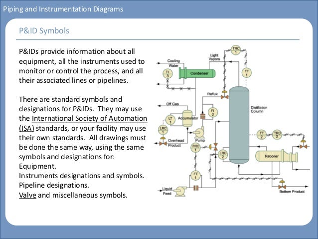
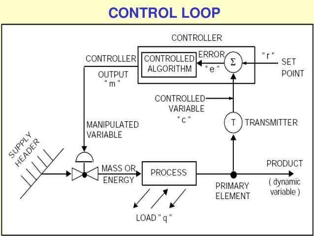
Instrumentation and control of an oil refinery and its monitoring
At this time I will tell my experience when I work on oil supplier and contractor in Java island, when I review many and enter many oil refineries and manufacture system also kind of good petroleum to be produced to become efficient petroleum and effective, usually good petroleum is petroleum from raw material that is somewhat blackened whereas bad for processed which color is rather yellowish brass. each oil refinery has a control room chamber that processes the work system in each refinery, each refinery has a laboratory space for oil testing sent from exploration and also has a control room that looks at the work system and program of all existing refineries. space control room equipped with special tools both for human and instrumentation and instrumentation tools and control either electro mechanic or electronic sensor as a means of detecting working system of refinery or oil refinery or oil-making process from the beginning to become a petroleum that can be used for day-to-day interests.


How Kerosene is made ?

Kerosene is an oil distillate commonly used as a fuel or solvent. It is a thin, clear liquid consisting of a mixture of hydrocarbons that boil between 302°F and 527°F (150°C and 275°C). While kerosene can be extracted from coal, oil shale, and wood, it is primarily derived from refined petroleum. Before electric lights became popular, kerosene was widely used in oil lamps and was one of the most important refinery products. Today kerosene is primarily used as a heating oil, as fuel in jet engines, and as a solvent for insecticide sprays.
Kerosene was an important commodity in the days before electric lighting and it was the first material to be chemically extracted on a large commercial scale. Mass refinement of kerosene and other petroleum products actually began in 1859 when oil was discovered in the United States. An entire industry evolved to develop oil drilling and purification techniques. Kerosene continued to be the most important refinery product throughout the late 1890s and early 1900s. It was surpassed by gasoline in the 1920s with the increasing popularity of the internal combustion engine. Other uses were found for kerosene after the demise of oil lamps, and today it is primarily used in residential heating and as a fuel additive. In the late 1990s, annual production of kerosene had grown to approximately 1 billion gal (3.8 billion 1) in the United States alone.
Kerosene is extracted from a mixture of petroleum chemicals found deep within the earth. This mixture consists of oil, rocks, water, and other contaminates in subterranean reservoirs made of porous layers of sandstone and carbonate rock. The oil itself is derived from decayed organisms that were buried along with the sediments of early geological eras. Over tens of millions of years, this organic residue was converted to petroleum by a pair of complex chemical processes known as diagenesis and catagensis. Diagenesis, which occurs below 122°F (50°C), involves both microbial activity and chemical reactions such as dehydration, condensation, cyclization, and polymerization. Catagenesis occurs between 122°F and 392°F (50°C and 200°C) and involves thermocatalytic cracking, decarboxylation, and hydrogen disproportionation. The combination of these complex reactions creates the hydrocarbon mixture known as petroleum.
The Manufacturing
Process
Crude oil recovery
- 1 The first step in the manufacture of kerosene is to collect the crude oil. Most oil supplies are buried deep beneath the earth and there are three primary types of drilling operations used to bring it to the surface. One method, Cable-Tooled Drilling, involves using a jackhammer chisel to dislodge rock and dirt to create a tunnel to reach oil deposits that reside just below the earth's surface. A second process, Rotary Drilling, is used to reach oil reservoirs that are much deeper underground. This process requires sinking a drill pipe with a rotating steel bit into the ground. This rotary drill spins rapidly to pulverize earth and rock. The third drilling process is Off Shore Drilling and it uses a large ocean borne platform to lower a shaft to the ocean floor.
- 2 When any of these drilling processes break into an underground reservoir, a geyser erupts as dissolved hydrocarbon gases push the crude oil to the surface. These gases will force about 20% of the oil out of the well. Water is then pumped into the well to flush more of the oil out. This flushing process will recover about 50% of the buried oil. By adding a surfactant to the water even more oil can be recovered. However, even with the most rigorous flushing it is still impossible to remove 100% of the oil trapped underground. The crude oil recovered is pumped into large storage tanks and transported to a refining site.
- 3 After the oil is collected, gross contaminants such as gases, water, and dirt are removed. Desalting is one cleansing operation that can be performed both in the oilfield and at the refinery site. After the oil has been washed, the water is separated from the oil. The properties of the crude oil are evaluated to determine which petroleum products can best be extracted from it. The key properties of interest include density, sulfur content, and other physical properties of the oil related to its carbon chain distribution. Since crude oil is a combination of many different hydrocarbon materials that are miscible in one another, it must be separated into its components before it can be turned into kerosene.
Separation
- 4 Distillation is one type of separation process involves heating the crude oil to separate its components. In this process the stream of oil is pumped into the bottom of a distillation column where it is heated. The lighter hydrocarbon components in the mixture rise to the top of the column and most of the high boiling-point fractions are left at the bottom. At the top of the column these lighter vapors reach the condenser which cools them and returns them to a liquid state. The columns used to separate lighter oils are proportionally tall and thin (up to 116 ft [35 m] tall) because they only require atmospheric pressure. Tall distillation columns can more efficiently separate hydrocarbon mixtures because they allow more time for the high boiling compounds to condense before they reach the top of the column. To separate some of the heavier fractions of oil, distillations columns must be operated at approximately one tenth of atmospheric pressure (75 mm Hg). These vacuum columns are structured to be very wide and short to help control pressure fluctuations. They can be over 40 ft (12 m) in diameter.
- 5 The condensed liquid fractions can be collected separately. The fraction that is collected between 302°F and 482°F (150°C and 250°C) is kerosene. By comparison, gasoline is distilled between 86°F and 410°F (30°C and 210°C). By recycling the distilled kerosene through the column multiple times its purity can be increased. This recycling process is known as refluxing.
Purification
- 6 Once the oil has been distilled into its fractions, further processing in a series of chemical reactors is necessary to create kerosene. Catalytic reforming, akylkation, catalytic cracking, and hydroprocessing are four of the major processing techniques used in the conversion of kerosene. These reactions are used to control the carbon chain distribution by adding or removing carbon atoms from the hydrocarbon backbone. These reaction processes involve transferring the crude oil fraction into a separate vessel where it is chemically converted to kerosene.
- 7 Once the kerosene has been reacted, additional extraction is required to remove secondary contaminants that can affect the oil's burning properties. Aromatic compounds, which are carbon ring structures such as benzene, are one class of contaminant that must be removed. Most extraction processes are conducted in large towers that maximize the contact time between the kerosene and the extraction solvent. Solvents are chosen based on the solubility of the impurities. In other words, the chemical impurities are more soluble in the solvent than they are the kerosene. Therefore, as the kerosene flows through the tower, the impurities will tend to be drawn into the solvent phase. Once the contaminants have been pulled out of the kerosene, the solvent is removed leaving the kerosene in a more purified state. The following extraction techniques are used to purify kerosene. The Udex extraction process became popular in the United States during the 1970s. It uses a class of chemicals known as glycols as solvents. Both diethylene glycol and tetraethylene glycol are used because they have a high affinity for aromatic compounds.
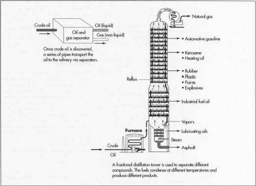
The distilling process of kerosene.
The Sulfolane process was created by the Shell company in 1962 and is still used in many extraction units 40 years later. The solvent used in this process is called sulfolane, and it is a strong polar compound that is more efficient than the glycol systems used in the Udex process. It has a greater heat capacity and greater chemical stability. This process uses a piece of equipment known as a rotating disk contractor to help purify the kerosene.
The Lurgi Arosolvan Process uses N-methyl-2-pyrrolidinone mixed with water or glycol which increases of selectivity of the solvent for contaminants. This process involves a multiple stage extracting towers up to 20 ft (6 m) in diameter and 116 ft (35 m) high.
The dimethyl sulfoxide process involves two separate extraction steps that increase the selectivity of the solvent for the aromatic contaminants. This allows extraction of these contaminants at lower temperatures. In addition, chemicals used in this process are non-toxic and relatively inexpensive. It uses a specialized column, known as a Kuhni column, that is up to 10 ft (3 m) in diameter.
The Union Carbide process uses the solvent tetraethylene glycol and adds a second extraction step. It is somewhat more cumbersome than other glycol processes.
The Formex process uses N-formyl morpholine and a small percentage of water as the solvent and is flexible enough to extract aromatics from a variety of hydrocarbon materials.
The Redox process (Recycle Extract Dual Extraction) is used for kerosene destined for use in diesel fuel. It improves the octane number of fuels by selectively removing aromatic contaminants. The low aromatic kerosene produced by these process is in high demand for aviation fuel and other military uses.
Final processing
- 8 After extraction is complete, the refined kerosene is stored in tanks for shipping. It is delivered by tank trucks to facilities where the kerosene is packaged for commercial use. Industrial kerosene is stored in large metal tanks, but it may be packaged in small quantities for commercial use. Metal containers may be used because kerosene is not a gas and does not require pressurized storage vessels. However, its flammability dictates that it must be handled as a hazardous substance.
Quality Control
The distillation and extraction processes are not completely efficient and some processing steps may have to be repeated to maximize the kerosene production. For example, some of the unconverted hydrocarbons may by separated by further distillation and recycled for another pass into the converter. By recycling the petroleum waste through the reaction sequence several times, the quality of kerosene production can be optimized.
By products/Waste
Some portion of the remaining petroleum fractions that can not be converted to kerosene may be used in other applications such as lubricating oil. In addition, some of the contaminants extracted during the purification process can be used commercially. These include certain aromatic compounds such as paraffin. The specifications for kerosene and these other petroleum byproducts are set by the American Society for Testing and Materials (ASTM) and the American Petroleum Institute (API).
The Future
The future of kerosene depends on the discovery of new applications as well as the development of new methods of production. New uses include increasing military demand for high grade kerosene to replace much of its diesel fuel with JP-8, which is a kerosene based jet fuel. The diesel fuel industry is also exploring a new process that involves adding kerosene to low sulfur diesel fuel to prevent it from gelling in cold weather. Commercial aviation may benefit by reducing the risk of jet fuel explosion by creating a new low-misting kerosene. In the residential sector, new and improved kerosene heaters that provide better protection from fire are anticipated to increase demand.
As demand for kerosene and its byproducts increases, new methods of refining and extracting kerosene will become even more important. One new method, developed by ExxonMobil, is a low-cost way to extract high purity normal paraffin from kerosene. This process uses ammonia that very efficiently absorbs the contaminants. This method uses vapor phase fixed-bed adsorption technology and yields a high level of paraffin that are greater than 90% pure.
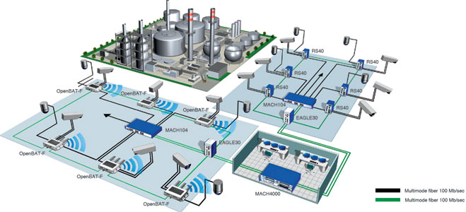
Industrial Ethernet for the Oil & Gas Industry
| |||||
|

To implement a reliable network backbone that can support 200 IP video feeds, the customer used the EDS-510A managed Ethernet switch to build a redundant Gigabit Ethernet network. Although the EDS-510A's two digital input channels are insufficient for extra monitoring devices, the ioLogik E2210 Active Ethernet I/O server was able to provide the necessary digital I/O channels. The built-in SNMP support and multiple I/O channels of ioLogik E2210 are available for control and monitoring by SNMP, no additional management software is required. In addition, status changes of each I/O channel can be actively reported by SNMP traps, so there is no need for data polling.

XXX . XXX Profession oil refinery control room operator
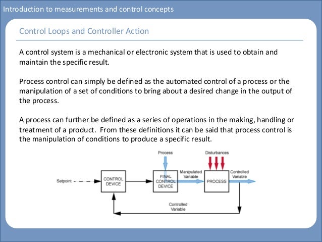
Oil refinery control room operators perform a range of tasks from the control room of an oil refinery. They monitor the processes through electronic representations shown on monitors, dials, and lights. Control room operators make changes to variables and communicate with other departments to make sure processes keep running smoothly and according to established procedures. They take appropriate actions in case of irregularities or emergencies.
Personality Type
- Realistic / Conventional
Knowledge
- Electronics The functioning of electronic circuit boards, processors, chips, and computer hardware and software, including programming and applications. Apply this knowledge to ensure electronic equipment runs smoothly.
- Petroleum The various facets of oil: its extraction, processing, constituents, uses, environmental issues, etc.
Skills
- Monitor equipment Monitoring equipment implies watching gauges, dials, or display screens to make sure a machine is working.
- Manage emergency procedures React quickly in case of emergency and set planned emergency procedures in motion.
- Write production reports Make up and complete shift schedules and production reports in a timely manner.
- Coordinate remote communications Direct network and radio communications between different operational units. Receive and transfer further radio or telecom messages or calls. These might include messages from the public, or the emergency services.
- Ensure compliance with safety legislation Implement safety programmes to comply with national laws and legislation. Ensure that equipment and processes are compliant with safety regulations.
- Conduct inter-shift communication Communicate relevant information about the conditions in the workplace, progress, events, and potential problems to the workers in the next shift.
- Use a computer Utilise computer equipment or digital devices to facilitate quality control, data management, and communication. Follow instructions given by a computer programme, create computer files or documents.
- Troubleshoot Identify operating problems, decide what to do about it and report accordingly.
XXX . XXX 4% zero Control room
A control room, operations center, or operations control center (OCC) is a room serving as a central space where a large physical facility or physically dispersed service can be monitored and controlled. A control room will often be part of a larger command center.
Control rooms are usually equipped with elaborate fire suppression and security systems to safeguard their contents and occupants, and to ensure continued operation in emergencies. In hazardous environments, the control room may also serve as an area of refuge for personnel trapped onsite. The rooms are typically crammed with equipment, mounted in multi-function rack mount cabinets to allow updating. The dense concentration of equipment often requires special electrical uninterruptible power supply (UPS) feeds and air conditioning.
Since the control equipment is intended to control other items in the surrounding facility, these (often fire-resistance rated) service rooms require many penetrations for cables. Due to routine equipment updates these penetrations are subject to frequent changes, so that a control room maintenance program must include vigilant firestop maintenance for code compliance.
Due to the nature of the sensitive equipment inside control room cabinets, it is useful to ensure the use of "T-rated" firestops, that are massive and thick enough to resist heat transmission to the inside of the control room. It is also common to place control rooms under positive pressure ventilation to prevent smoke or toxic gases from entering. If used, gaseous fire suppressants must occupy the space that is to be protected for a minimum period of time to be sure a fire can be completely extinguished. Openings in such spaces must, therefore, be kept to a minimum to prevent the escape of the suppression gas.
A mobile control room is designated as particularly in high risk facilities, such as a nuclear power station or a petrochemical facility. It can provided a guaranteed life support for the anticipated safety control. The design of a control room incorporates ergonomic and aesthetic features including optimum traffic flow, acoustics, illumination, and health and safety of the workers. Ergonomic considerations determine the placement of humans and equipment to ensure that operators can easily move into, out of, and around the control room, and can interact with each other without any hindrances during emergency situations; and to keep noise and other distractions to a minimum.
probe and solve Consolidation of refinery control rooms - Petroleum Technology Quarterly
The consolidation of control rooms was conducted in several refineries in the 1990s and early 2000s as a means of reducing the number of operators and improving efficiency for enhanced competitiveness. The characteristics of consolidated control rooms vary, reflecting the history of a refinery. However, the adverse business environment in recent times has meant that the oil industry has had to consider approaches other than consolidation. In many plants, migration of the distributed control system (DCS) gives an opportunity to investigate the control room configuration and operational management system for achieving safer, more stable and more efficient operation.
This article describes refinery modernisation activities that led towards an ideal refinery that enables safe, stable and efficient operation. In the example described, Yokogawa was asked to contribute to a major part of the modernisation relating to DCS migration and control room consolidation. Yokogawa offered the Refinery Operation Modernisation Service, one of its VigilantPlant Services, which features four solutions: consolidated refinery production control including consolidated control room design; operator training system (OTS); capture and amalgamation of best practices (SOPs); and safety instrumented system (SIS).
Major issues for modernisation
Over the years, the refiner had upgraded its units one by one, with the aim of creating a high-conversion refinery, and the operations department had also been expanded to as many as six operating sections responsible for each unit. In all, the refinery had four distributed control rooms and DCSs acting independently. The control systems were supplied by two vendors and were of several generations, because they had been introduced as process installations. This presented several challenges:
- The detailed design of the DCS varied among the different operations sections
- Each operations section had its own operational procedures
- There was a lack of communication between operations sections since they mainly relied on information carried through instrumentation signal cables or via the supervisory information system
- The CPU utilisation rate and the number of instruments to be handled by each DCS were approaching allowable limits due to the repeated expansion and modification of process units
- The segmented organisation resulted in differing requirements for the education and training of operators, different spare parts for the DCSs, and different procedures for the maintenance engineers.
Activities towards an ideal refinery
The refinery authorised a phased plan towards an ideal refinery to meet the demographic challenges presented by knowledgeable veterans retiring and their places being taken by less experienced personnel, with a target date of 2013 (see Figure 1). In Phase 1, the consolidation of control rooms and the migration of the production control system were scheduled to be completed in June 2009. After the physical migration, organisational re-engineering was planned, as Phase 2, to establish the "consolidated operation centre" by 2011.
This project was triggered by a report by a business improvement working group to the refinery's top management in 2004. Until the formal launch of the project in 2007, the control room consolidation working group in the refinery identified the issues involved for safe, stable and efficient operation, as well as the training of younger operators for knowledge transfer. During this preparation phase, Yokogawa proposed a visual concept of an ideal refinery and the human-centred configuration of the consolidated control room, including its migration plan, in collaboration with the refiner's working group. In Phase 1 of the project, named the control room consolidation project, Yokogawa undertook the migration work including control room design.
Control room consolidation project
The refinery was operated by six sections: the on-site plant sections 1-4, the power and utilities section, and the offsite section, distributed in four control rooms. The initial study concluded that the control rooms should be consolidated into one by constructing a new control room, and that the control systems should be migrated, taking the opportunity of a large turnaround scheduled for June 2009. The planned DCS migration was not a simple replacement of each existing DCS system, but introduced a supervisory DCS that could control and monitor the whole plant. It also included implementation of the consolidated safety instrumented system (SIS) to enhance the safety of the entire plant.

Figure 1 Activities toward an ideal refinery
The main purposes of the control room consolidation and the system migration are as follows:- Enhance agility and co-operativeness in the refinery, and enhance the integrity of information systems throughout the supply chain, from plant operation to shipping
- Improve safety and establish a more efficient operation by systematic operator training to retain operational expertise, capturing operational procedures and amalgamating the derived best practices as improved standard operational procedures
- Prepare the environment for the above two major aims by constructing a new consolidated control room and a new system, thus establishing operational integrity.
- The consolidated refinery production control system: this includes not only the consolidation of control rooms and the migration of the control system planned in Phase 1, but also further system enhancement for improving plant operation and for operator training scheduled in Phase 2, implemented in 2011
- Highly efficient operation
- Safety management
- Refinery-wide operation: in the near future, refinery operation will be integrated into one unit, from crude processing to product shipping
- Operator training for sharing and improving operational expertise: the same DCS information is available everywhere in the refinery, in meeting rooms, in the field and in the office. Operational assistance systems are standardised
- High availability of the systems: the intention is to improve availability of each device, network and piece of software by designing the systems with full consideration of systems operation and maintenance.
Yokogawa proposed the Refinery Operation Modernisation Service to solve the various issues in the refinery. It consists of four solutions: the consolidated refinery production control system; consolidated control room design; OTS; and SIS for the refinery.
The proposed consolidated refinery production control system utilises the full functions of Centum VP, Yokogawa's latest integrated production control system. The system can realise efficient refinery operation in a consolidated control room by covering a broad range of plant areas and by incorporating many applications such as advanced process control, operation assistance, alarm analysis and SISs (see Figures 2 and 3).
The human-machine interface (HMI) for the consolidated control system was configured by utilising the HMI technology of the Centum VP. The new HMI can contribute to safe, stable and efficient operation in the following ways:
- Improved operability by adopting a multi-window function
- Integrated operation of multiple systems—including DCS, SIS, advanced process control system, operation assistance system, alarm analysis system, and supervisory emergency shutdown system —using integrated terminal functions
- Custom-designed furniture for comfortable operation and dual monitoring displays for sufficient information
- Reduced noise because of the fanless housing design
- Dedicated operational HMI console for temporary use
- A space-saving layout by adopting portable HMI consoles that are online detachable from the DCS bus.
The supervisory DCS is installed on top of each unit DCS that collects refinery-wide data, such as utility data through the refinery-wide DCS bus, and monitors the performance of the refinery. The supervisory DCS also has a refinery-wide control function such as utility balance, and plant manipulations can be carried out through local DCS HMI.
In the future, this supervisory DCS will play an important role for total production management of the refinery, from crude processing to product shipping.

Figure 2 Overview of the consolidated refinery production control system
Large channel capacity and high-speed DCS busThe consolidation of multiple large systems such as the total refinery system without losing information was achieved by a high-speed network. Yokogawa provides the Vnet/IP large channel-capacity DCS bus, which eases the restrictions on data communication between devices and systems.
DCS everywhere using a ubiquitous LAN
 |
| Figure 3 Illustration of consolidated control room concept |
Ease of maintenance
Large-scale complex systems require vigilant design to improve integrity and availability. Highreliability design policies including redundancy, duplication and quick system recovery are adopted. In addition, remote maintenance enables problems to be detected and solved at an early stage, leading to stable operation.
Human-centred design for consolidated control room
For the new consolidated control room, Yokogawa designed the layout, lighting and acoustic systems, taking into account ergonomic factors such as operability, workability, visibility and comfort. The control room layout also takes such factors as communication between sections and future expandability into consideration. As a result, the new control room is human-centred in terms of both comfort and vigilance (see Figure 3).
Operator training system
In 2008, the refinery introduced a new type of fluid catalytic cracker as its second unit. The new unit was very different from the existing one in operation, and so the refinery decided to introduce an OTS to ensure a quick start-up. The OTS was configured by combining Yokogawa's OmegaLand dynamic simulator alongside the DCS. Moreover, since the existing DCS was migrated to the latest version of Centum VP accompanied by the consolidation of control rooms, the OTS was also used for operator training of the new operation screens for the consolidated refinery production control system. This reduced the risk involved changing a DCS vendor and enabled quick start-up of the new DCS.
The OTS was set up in the newly constructed training room, and a new system for the crude distillation unit (CDU) was also developed to transfer the expertise of veteran operators.
Safety instrumented system
Taking the opportunity of DCS migration, the consolidated SIS was installed to enhance the safety of the entire refinery. The existing emergency shutdown (ESD) system using a conventional relay system was replaced with the SIL3-certified ProSafe-RS safety instrumented system, which meets all requirements covered by IEC 61508/JIS C 0508.
The SIS is part of the core infrastructure of the consolidated refinery production control system for safe and efficient operation (see Figure 4). The system can also be integrated with the DCS and ESD triggers, and events can be seen on the same HMI of the DCS. Emergency responses can be carried out on the HMI display of the DCS along with the new ESD console.
The reliability of the ESD system has been improved by the following features of ProSafe-RS:
- Diagnosis of the entire path from a system I/O card to emergency shutdown valves without obstacles such as hard relays
- Diagnosis of wiring from ESD contact signals including pressure switches
- Partial stroke test of emergency shutdown valves.

Figure 4 Safety instrumentation for the refinery based on ProSafe-RS
Migration processThe migration of the DCSs throughout the refinery and the migration of the existing ESD circuit to ProSafe-RS had to be completed during the short period of the scheduled turnaround in 2009. Table 1 shows the outline of the migration. Although it was a big project, it was completed in just 14 days.
System migration in such a short time and without any trouble was achieved thanks to meticulous preparation, detailed scheduling including resource allocation, a startup team supported by a backup team, specialists and subsystem engineers capable of quick troubleshooting, and a "hot line" to the quality assurance department.
Effects of control room consolidation
Among the many positive effects of the consolidation of the control rooms, the greatest is a sense of unity and face-to-face communication between people, allowing them to broaden their outlook by working together.
The renovated control room makes people feel relaxed and secure, and as a result they can concentrate on plant operation. Improvements in data integrity and data availability accelerate communication between units to optimise the operation among units. Standardisation of operational procedures, a secondary effect of the system consolidation, has promoted the transfer of operational expertise. Introduction of the SIS has enhanced safety. Another intangible but valuable effect of the renovation is the motivation of young operators. They are stimulated by the new control room, the new systems and the new way of plant operation, as are all the people in the refinery.
Continuous improvement activities towards establishing the production centre are expected to create a variety of effects in the future.
Outline of the consolidation during the 2009 scheduled turnaround
| Item | Description |
|---|---|
| Control room | Consolidating four control rooms into one |
| Yokogawa's start-up team | Up to 60 |
| Total loop and interlock tests | Switched signal: approx 15 000 points, completed in 14 days |
| System migration | Simultaneous migration of 144 field devices. Breakdown: HMI: 44; server: 16; control station: 68; safety controller: 14 |
The consolidation of control rooms and the migration of the production system prepared the infrastructure for further improvements at the refinery. The next steps towards organisational and operation procedural renovations have started.
Increased productivity of operators as a result of consolidation will be used for further improvement of plant operation as well as human resource development. Yokogawa continues the development of industry solutions such as Production Instructor and Exapilot, contributing to the tasks of capturing, amalgamating and optimising operational procedures as a contribution to operator effectiveness.
The consolidated control room is now the centre of operation and it will be an enabler of two-way optimisation of refinery operation, both refinerywide and organisation-wide. The refinery can be operated refinery-wide as one unit, while organisational integration can realise flexible production to accommodate a changing environment.


XXX . XXX 4%zero null 0 1 Processing & Refining Crude Oil

Operators control the refining processes using hi-tech computers located in control centers situated throughout the refinery.
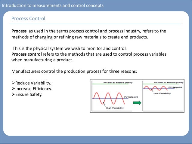
Hi-Tech Process Control
Using the latest electronic technology to monitor and control the plants, operators run the process units 24 hours a day, 7 days a week. From control rooms located in each Operations area, operators use a computer-driven process control system with console screens that display color interactive graphics of the plants and real-time data on the status of the plants. The process control system allows operators to “fine-tune” the processes and respond immediately to process changes. With redundancy designed into the control system, safe operations are assured in the event of plant upset.Refining’s Basic Steps
Most refineries, regardless of complexity, perform a few basic steps in the refining process: DISTILLATION, CRACKING, TREATING and REFORMING. These processes occur in our main operating areas – Crude/Aromatics, Cracking I, RDS/Coker, Cracking II, and at the Sulfur Recovery Unit.1. Distillation
Modern distillation involves pumping oil through pipes in hot furnaces and separating light hydrocarbon molecules from heavy ones in downstream distillation towers – the tall, narrow columns that give refineries their distinctive skylines.The Pascagoula Refinery’s refining process begins when crude oil is distilled in two large Crude Units that have three distillation columns, one that operates at near atmospheric pressure, and two others that operate at less than atmospheric pressure, i.e., a vacuum.
During this process, the lightest materials, like propane and butane, vaporize and rise to the top of the first atmospheric column. Medium weight materials, including gasoline, jet and diesel fuels, condense in the middle. Heavy materials, called gas oils, condense in the lower portion of the atmospheric column. The heaviest tar-like material, called residuum, is referred to as the “bottom of the barrel” because it never really rises.

This distillation process is repeated in many other plants as the oil is further refined to make various products.
In some cases, distillation columns are operated at less than atmospheric pressure (vacuum) to lower the temperature at which a hydrocarbon mixture boils. This “vacuum distillation” (VDU) reduces the chance of thermal decomposition (cracking) due to over heating the mixture.
As part of the 2003 Clean Fuels Project, the Pascagoula Refinery added a new low-pressure vacuum column to the Crude I Unit and converted the RDS/Coker’s VDU into a second vacuum column for the Crude II Unit. These and other distillation upgrades improved gas oil recovery and decreased residuum volume.
Using the most up-to-date computer control systems, refinery operators precisely control the temperatures in the distillation columns which are designed with pipes to withdraw the various types of products where they condense. Products from the top, middle and bottom of the column travel through these pipes to different plants for further refining.
2. Cracking
Since the marketplace establishes product value, our competitive edge depends on how efficiently we can convert middle distillate, gas oil and residuum into the highest value products.At the Pascagoula Refinery, we convert middle distillate, gas oil and residuum into primarily gasoline, jet and diesel fuels by using a series of processing plants that literally “crack” large, heavy molecules into smaller, lighter ones.
Heat and catalysts are used to convert the heavier oils to lighter products using three “cracking” methods: fluid catalytic cracking (FCC), hydrocracking (Isomax), and coking (or thermal-cracking).

The Fluid Catalytic Cracker (FCC) uses high temperature and catalyst to crack 86,000 barrels (3.6 million gallons) each day of heavy gas oil mostly into gasoline. Hydrocracking uses catalysts to react gas oil and hydrogen under high pressure and high temperature to make both jet fuel and gasoline.
Also, about 58,000 barrels (2.4 million gallons) of lighter gas oil is converted daily in two Isomax Units, using this hydrocracking process.

We blend most of the products from the FCC and the Isomaxes directly into transportation fuels, i.e., gasoline, diesel and jet fuel. We burn the lightest molecules as fuel for the refinery’s furnaces, thus conserving natural gas and minimizing waste.
In the Delayed Coking Unit (Coker), 98,000 barrels a day of low-value residuum is converted (using the coking, or thermal-cracking process) to high-value light products, producing petroleum coke as a by-product. The large residuum molecules are cracked into smaller molecules when the residuum is held in a coke drum at a high temperature for a period of time. Only solid coke remains and must be drilled from the coke drums.
Modifications to the refinery during its 2003 Clean Fuels Project increased residuum volume going to the Coker Unit. The project increased coke handling capacity and replaced the 150 metric-ton coke drums with new 300 metric-ton drums to handle the increased residuum volume.
The Coker typically produces more than 6,000 tons a day of petroleum coke, which is sold for use as fuel or in cement manufacturing.
Combining
While the cracking processes break most of the gas oil into gasoline and jet fuel, they also break off some pieces that are lighter than gasoline. Since Pascagoula Refinery’s primary focus is on making transportation fuels, we recombine 14,800 barrels (622,000 gallons) each day of lighter components in two Alkylation Units. This process takes the small molecules and recombines them in the presence of sulfuric acid catalyst to convert them into high octane gasoline.
3. Treating (Removing Impurities)
The products from the Crude Units and the feeds to other units contain some natural impurities, such as sulfur and nitrogen. Using a process called hydrotreating (a milder version of hydrocracking), these impurities are removed to reduce air pollution when our fuels are used.Because about 80 percent of the crude oil processed by the Pascagoula Refinery is heavier oils that are high in sulfur and nitrogen, various treating units throughout the refinery work to remove these impurities.
In the RDS Unit’s six 1,000-ton reactors, sulfur and nitrogen are removed from FCC feed stream. The sulfur is converted to hydrogen sulfide and sent to the Sulfur Unit where it is converted into elemental sulfur. Nitrogen is transformed into ammonia which is removed from the process by water-washing. Later, the water is treated to recover the ammonia as a pure product for use in the production of fertilizer.
The RDS’s Unit main product, low sulfur vacuum gas oil, is fed to the FCC (fluid catalytic cracker) Unit which then cracks it into high value products such as gasoline and diesel.
4. Reforming
Octane rating is a key measurement of how well a gasoline performs in an automobile engine. Much of the gasoline that comes from the Crude Units or from the Cracking Units does not have enough octane to burn well in cars.The gasoline process streams in the refinery that have a fairly low octane rating are sent to a Reforming Unit where their octane levels are boosted. These reforming units employ precious-metal catalysts – platinum and rhenium – and thereby get the name “rheniformers.” In the reforming process, hydrocarbon molecules are “reformed” into high octane gasoline components. For example, methyl cyclohexane is reformed into toluene.

The reforming process actually removes hydrogen from low-octane gasoline. The hydrogen is used throughout the refinery in various cracking (hydrocracking) and treating (hydrotreating) units.
Our refinery operates three catalytic reformers, where we rearrange and change 71,000 barrels (about 3 million gallons) of gasoline per day to give it the high octane cars need.

Product testing
Blending
A final and critical step is the blending of our products. Gasoline, for example, is blended from treated components made in several processing units. Blending and Shipping Area operators precisely combine these to ensure that the blend has the right octane level, vapor pressure rating and other important specifications. All products are blended in a similar fashion.Quality Control
In the refinery’s modernly-equipped Laboratory, chemists and technicians conduct quality assurance tests on all finished products, including checking gasoline for proper octane rating. Techron® Chevron’s patented performance booster, is added to gasoline at the company’s marketing terminals, one of which is located at the Pascagoula Refinery.XXX . XXX 4%zero null 0 1 2 3 4 INSTRUMENTATION SOLUTIONS FOR PETROLEUM REFINING PROCESS CONTROL
PRODUCTS INSTRUMENTATION AND CONTROL REFINERY : | |||||
|


Introduction Process Control System
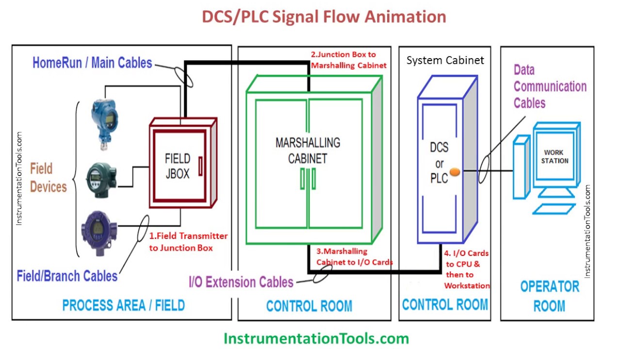
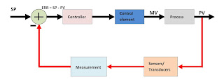
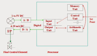
A process control system is made up of a group of electronic devices that provide stability, accuracy and eliminate harmful transition statuses in production processes. Operating systems can have different arrangements and implementation, from energy supply units to machines. As technology quickly progresses, many complex operational tasks have been solved by connecting programmable logic controllers and a central computer. Beside connections with devices (e.g., operating panels, motors, sensors, switches, valves, etc.) possibilities for communication among instruments are so great that they allow a high level of exploitation and process coordination. In addition, there is greater flexibility in realizing a process control system. Each component of a process control system plays an important role, regardless of its size. For example, without a sensor, the PLC wouldn't know what is going on during a process. In an automated system, a PLC controller is usually the central part of a process control system. With the execution of a program stored in program memory, PLC continuously monitors status of the system through signals from input devices. Based on the logic implemented in the program, PLC determines which actions need to be executed with output instruments. To run more complex processes it is possible to connect more PLC controllers to a central computer. A system could look like the one pictured below:
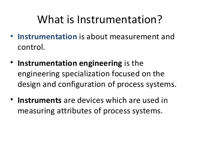
XXX . XXX 4%zero null 0 1 2 3 4 5 6 7 Industrial Instrumentation and Control
concepts and principles that govern the operation of industrial plants. Concepts associated with measurements of flow, level, temperature and pressure, electronics and pneumatics instrumentation, control loops, PID control, and others will be addressed.
Instrumentation and control are interdisciplinary fields. They require knowledge of chemistry, mechanics, electricity and magnetism, electronics, microcontrollers and microprocessors, software languages, process control, and even more such as the principles of pneumatics and hydraulics and communications.
This is what makes instrumentation and control so interesting and instructive.
In this article and the next, I will give a complete overview of the basic principles of instrumentation and control (I & C) used for the functioning and operation of industrial plants such as those involving oil and gas, pulp and paper, sugar, pharmaceutical products, food, and chemicals.
First, we'll need to cover how to measure, and to measure we need a measurement instrument.
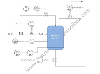
Consider the example of Figure 1.
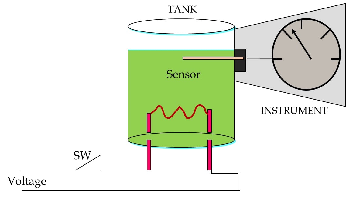
When the switch is closed, the resistor generates heat, increasing the temperature of the liquid in the tank. This increase is detected by the measurement instrument and shown on the scale of that instrument.
We can get the information on the physical changes in a process using direct indication or a recorder.


Usually, the measurement information generated by an instrument must be sent to a control center (or control room) that is physically distant from the instrument. In general, this information must conform to established specifications.

When an instrument has the ability to send information, we call it a transmitter (XMTR).
Another classification is pneumatic instruments vs. electrical/electronic instruments.
One of the advantages of these instruments is that they do not consume electricity, so they can be used in areas where it would be dangerous or inconvenient to use electrical power. They work with a single variable, are imprecise instruments, are affected by vibrations and temperature changes, and have high maintenance requirements. The output signal of the transmitters is between 3 and 15 psi, and the maximum transmission distance is approximately 200 meters.


Span: Calculated as the maximum value of the range minus the minimum value of the range. Span is expressed with a single number in process units, e.g., 120 °C, 30 V, 150 liters per second.
Elevation: If the lower limit of the range is a positive value, this lower limit is the elevation. Example: If the range is 50 °C to 200 °C, we can say that the elevation is 50 °C or 33.3% of the span.
Depression (also referred to as suppression): If the lower limit of the range is negative, the absolute value of this lower limit is the depression. Example: If the range is -10 °C to 80 °C, we can say that the depression is 10 °C or 11.1% of the span.
Overrange: When a device is calibrated to operate within a certain range but may be subjected to values above or below that range, then it requires a protection mechanism to prevent damage to the instrument or to prevent the indicator from exceeding its upper or lower limit. When the measured values are above the maximum value, we have positive overrange. When the measured values are below the minimum value, we have negative overrange.

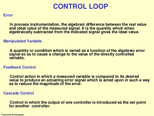
Error: The difference between the measured value and the actual (or expected, or desired) value of a physical variable. The error can be positive or negative. When the measured value is greater than the actual value, the error is positive. When the measured value is less than the actual value, the error is negative.
Accuracy: A number that defines the limits of the error. When we say that an instrument has an accuracy of 0.1% of the span, this means that anywhere within the range, the readings do not differ from the actual value by more than 0.1% of the span.
We have an oil tank where we are required to continuously measure the temperature. The operating conditions for this process are as follows:

This transmitter must have the following characteristics:
++++++++++++++++++++++++++++++++++++++++++++++++++++++++++++++++++++++++
INSTRUMENTATION CONTROL REFINERY ON ELECTRONICS MONITORING

+++++++++++++++++++++++++++++++++++++++++++++++++++++++++++++++++++++++++
concepts and principles that govern the operation of industrial plants. Concepts associated with measurements of flow, level, temperature and pressure, electronics and pneumatics instrumentation, control loops, PID control, and others will be addressed.
Someone once asked a colleague what his occupation was. He replied without hesitation, "I am an instrumentation and control engineer." "And what is that?" asked his interlocutor. "...Oh. Oh ... I'm in trouble," thought the engineer.
To explain what a mechanical, electrical, chemical, or electrical engineer does is relatively easy, but it is another story to concisely describe the work performed by an engineer who specializes in instrumentation and control.Instrumentation and control are interdisciplinary fields. They require knowledge of chemistry, mechanics, electricity and magnetism, electronics, microcontrollers and microprocessors, software languages, process control, and even more such as the principles of pneumatics and hydraulics and communications.
This is what makes instrumentation and control so interesting and instructive.
In this article and the next, I will give a complete overview of the basic principles of instrumentation and control (I & C) used for the functioning and operation of industrial plants such as those involving oil and gas, pulp and paper, sugar, pharmaceutical products, food, and chemicals.
First, we'll need to cover how to measure, and to measure we need a measurement instrument.
What is a measurement instrument?
A measurement instrument is a device capable of detecting change, physical or otherwise, in a particular process. It then converts these physical changes into some form of information understandable by the user.Consider the example of Figure 1.
Figure 1: An example of a measurement instrument
When the switch is closed, the resistor generates heat, increasing the temperature of the liquid in the tank. This increase is detected by the measurement instrument and shown on the scale of that instrument.
We can get the information on the physical changes in a process using direct indication or a recorder.
Indication
This is the simplest form of measurement; it allows us to know the current state of the variable.Figure 2: Monitoring a variable via indication
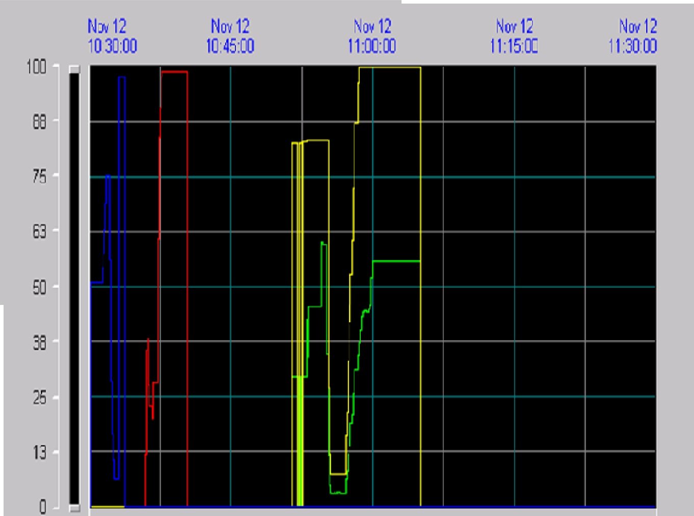
Recorder
A device that can store data allows us to observe the current state of the variable and how it behaved in the past. A recorder provides us with the history of the variable.Figure 3: A display showing how measurements have changed over time
Elements of a Measurement Instrument
Measurement instruments consist primarily of the following parts:- Sensor: This element is a device that experiences changes in its physical properties as a result of changes in the process it's measuring.
- Amplifier / Conditioner: Changes detected by the sensor may be very small, so they must be amplified and then conditioned such that they can be properly displayed.
- Display: The measured data should be presented in an understandable way. This can be done using a graduated instrument or an electronic display. Sometimes the display additionally acts as a recorder in order to convey the measurement's history or trends.
Figure 4: Elements of a measurement instrument
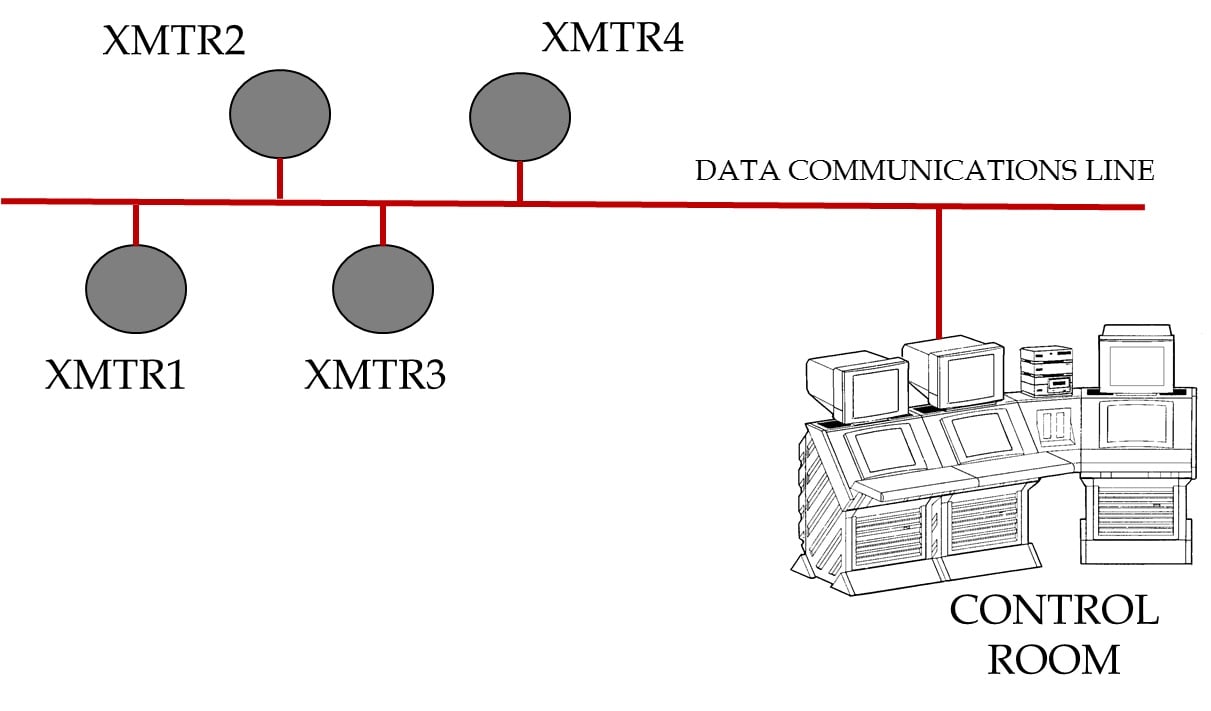
Usually, the measurement information generated by an instrument must be sent to a control center (or control room) that is physically distant from the instrument. In general, this information must conform to established specifications.
Figure 5: Measurement information is sent from the instrument to the control room
When an instrument has the ability to send information, we call it a transmitter (XMTR).
Classification of Instruments
There are different classifications for measurement instruments. We can classify them, for example, as in-field instruments or panel instruments. The in-field instrument is installed close to the process or measuring point. It must be physically robust if it will be exposed to harsh environmental conditions. Panel instruments are in a controlled-environment room (often a clean space with air conditioning and controlled humidity).Another classification is pneumatic instruments vs. electrical/electronic instruments.
Pneumatic Instruments
As the name suggests, these are devices that are powered by air.One of the advantages of these instruments is that they do not consume electricity, so they can be used in areas where it would be dangerous or inconvenient to use electrical power. They work with a single variable, are imprecise instruments, are affected by vibrations and temperature changes, and have high maintenance requirements. The output signal of the transmitters is between 3 and 15 psi, and the maximum transmission distance is approximately 200 meters.
Figure 6: Basic diagram of a pneumatic instrument
Electrical / Electronic Instruments
Electronic instruments can be divided into three general categories: analog, smart analog, and digital.Analog:
- Output signal: 4 - 20 mA
- Transmission distance: 1200 m (typical)
- Data for one variable is transmitted
- Good accuracy
- Easy maintenance
Figure 7: Basic diagram of an electronic instrument (XMTR)
Smart Analog:
- Characterization of the sensor as measuring temperature, static pressure, etc.
- Excellent accuracy
- Self-diagnosis (i.e., the sensor can analyze problems in its own functionality)
- One variable
Digital:
- Multiple instruments can use a single cable
- Transmission of multiple values for each instrument (process variables, calibration, diagnostics, range)
- Distance: approximately 1900 m without a repeater
- Data capacity is influenced by the mode of transmission (cable, fiber optic, wireless)
Figure 8: Digital transmitters
General Concepts
Range: The region between the limits within which a variable is measured. It indicates the minimum and maximum values that limit the region. The range is expressed with two numbers, e.g., 10 to 20 °C, 10 to 150 V, 0 to 100%Span: Calculated as the maximum value of the range minus the minimum value of the range. Span is expressed with a single number in process units, e.g., 120 °C, 30 V, 150 liters per second.
Elevation: If the lower limit of the range is a positive value, this lower limit is the elevation. Example: If the range is 50 °C to 200 °C, we can say that the elevation is 50 °C or 33.3% of the span.
Depression (also referred to as suppression): If the lower limit of the range is negative, the absolute value of this lower limit is the depression. Example: If the range is -10 °C to 80 °C, we can say that the depression is 10 °C or 11.1% of the span.
Overrange: When a device is calibrated to operate within a certain range but may be subjected to values above or below that range, then it requires a protection mechanism to prevent damage to the instrument or to prevent the indicator from exceeding its upper or lower limit. When the measured values are above the maximum value, we have positive overrange. When the measured values are below the minimum value, we have negative overrange.
Figure 9: Examples of range, span, elevation, and depression
If measured > actual, error > 0
If measured < actual, error < 0
The error can be expressed- in engineering units (e.g., °C, psi)
- as a percentage of the span (e.g., +/- 3% of the span)
- as a percentage of the measurement (e.g., +/- 5% of the measurement)
Accuracy: A number that defines the limits of the error. When we say that an instrument has an accuracy of 0.1% of the span, this means that anywhere within the range, the readings do not differ from the actual value by more than 0.1% of the span.
An Example
For a better understanding of the concepts expressed above, consider the following example.We have an oil tank where we are required to continuously measure the temperature. The operating conditions for this process are as follows:
- Minimum temperature: -10 °C
- Maximum temperature: 90 °C
- The measurement accuracy must be 1% of the span or better
- The temperature measurement must be displayed locally and remotely
Figure 10: Our example system
First, we must select a measuring instrument that allows us to measure the temperature of the liquid in the tank. Since the information should be available locally and remotely, we will choose a temperature transmitter.
This transmitter must have the following characteristics:
- Range: -10 °C to 90 °C
- Span: 90 °C - (-10 °C) = 100 °C
- Depression: 10 °C or 10% of the span
- Accuracy: 1% of the span = 1% × 100 °C = 1 °C
- This accuracy of 1% ensures that, in each measurement or temperature reading, variation or errors will not exceed +/- 1 °C
Conclusion
In this article we have discussed measurement devices and fundamental measurement concepts in the context of instrumentation and control systems. We also looked at a simple example system involving a heating element and an instrument that can collect and transmit temperature data. In the next article, we will cover the four basic variables used in industrial applications: flow, level, temperature, and pressure. Also, we will discuss various sensors such as orifice plates, thermocouples, and RTDs, and we will review instruments and transmitters used for measuring these four physical variables.++++++++++++++++++++++++++++++++++++++++++++++++++++++++++++++++++++++++
INSTRUMENTATION CONTROL REFINERY ON ELECTRONICS MONITORING
+++++++++++++++++++++++++++++++++++++++++++++++++++++++++++++++++++++++++
Tidak ada komentar:
Posting Komentar