

Integrated Circuit Does to our Circuit
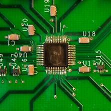

The integrated circuit
An integrated circuit is simply any type of circuit, made to fit onto a chip. Sometimes, we call it a chip, a microchip or an IC (Integrated Circuit).
What It Does To our Circuit
An integrated circuit is any kind of circuit that is integrated onto a chip. Therefore, what it does to your circuit depends on the type of circuit. It can be an amplifier, a radio transmitter, a microcontroller or any other circuit you can think of.
The chip I made was a Ultra-Wideband (UWB) Radar chip. It’s a really cool technology. Check out some of the radar circuits I have made using this technology.
By making a circuit on a small chip, it’s much easier to make advanced projects. Let’s say you want to make a tracking device for your car. You can find a GPS chip for positioning, a GSM chip to send text messages, and a microcontroller chip to control everything. Then create a printed circuit board design to connect them all.
Integrated circuits make your life building circuits, so much easier.
How Do we Make an Integrated Circuit?
You create an integrated circuit by drawing different rectangles in a computer program for designing chips. The different rectangles represent different types of material. This sounds a bit weird. But every component is made up from different materials
Here is the chip I designed back in 2008:
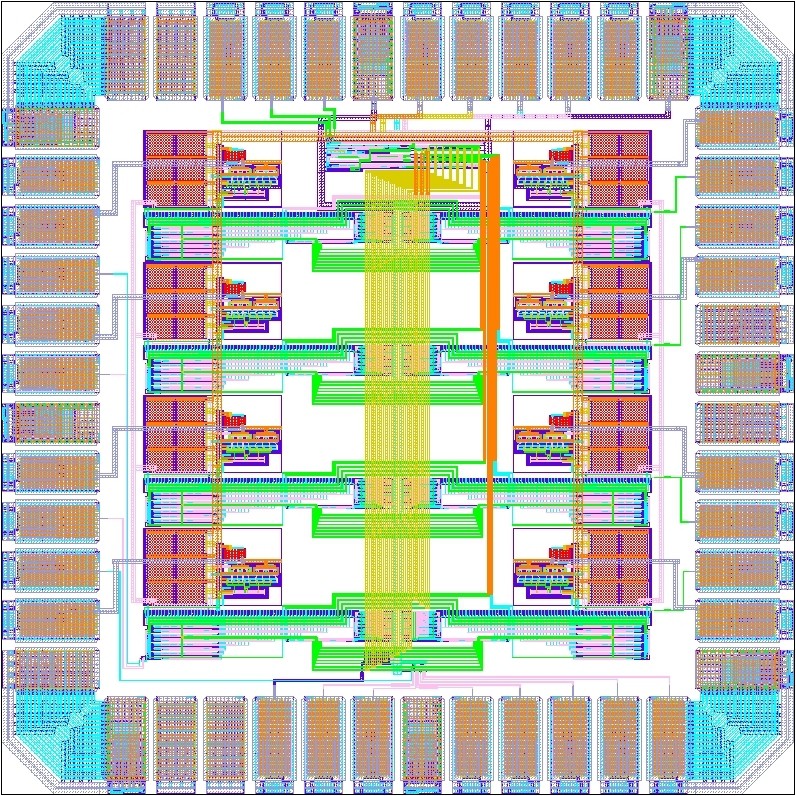
This design is then transferred to a silicon wafer by using a complex process of etching and stereolithography.
How To Figure Out What a Specific Chip Does
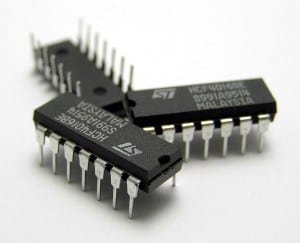 If you have an integrated circuit, but you don’t know what it does, don’t worry. Usually it very easy to figure out what it does. Just take the model number that you find on the top, and type it into Google with “datasheet” after.
Usually, you will find a PDF-file of the datasheet. The datasheet is a technical document that describes the component. By opening and reading the first page of the datasheet, you should be able to get an understanding of what it does.
But, if your chip does not have anything written on it, it is almost impossible to figure out what it does.
what exactly is an integrated circuit? In its most basic form, an IC is simply a collection of teeny tiny electronic components organized on a piece of silicon. Compared to their larger brothers and sisters, the components found on an IC can be nearly microscopic in size, and each IC contains a unique collection of diodes, transistors, microprocessors, capacitors, etc… all found on something smaller than a dime!

All of your standard, common components have been miniaturized to fit inside this integrated circuit. (Image source)
What’s the benefit of putting all of these components together into one integrated circuit? There are many! Here’s just a few:
- Space Savers. Instead of requiring an entire printed circuit board filled with a ton of transistors, diodes, and other parts, you can get all of that advanced functionality in a fraction of the size.
- Greater Complexity. The level of complexity found in such a small package has allowed us to build some pretty amazing things. Like self-landing rockets, and satellites with built-in navigation. Imagine trying to make those things with billions of through-hole components!
- Common Goals. By creating a tiny integrated circuit with an exact purpose, you can put a bunch of these together to all achieve a common goal. Need a tracking device for your car? One IC can provide GPS, another can send messages, and a final microcontroller IC can control all the data going back and forth.
And of course, you also have the benefit of taking all of those separate yet connected parts found on a conventional circuit and putting them all together in one place! That gives you all of that advanced functionality you need in a pre-made circuit without having to build it yourself!
The integrated circuit truly is the brains behind all of today’s electronic devices, and you’ll be hard pressed to not find them everywhere, like in radars, televisions, video processing, missiles, and yes, even juice makers! The list is endless. Just take a quick scan of all the electronic devices in your home, and you’re bound to find an IC inside of nearly all of them. But from where did they come?
The Beginnings of the Integrated Circuit
Before the integrated circuit rolled around, vacuum tubes were the kings of the day, being used to amplify electrical signals and power computers the size of an entire room! But these monolithic vacuum tubes broke down regularly and pumped out a ton of heat in the process.
So in 1947, three American physicists one-upped the vacuum tube by making the first transistor. These things were a fraction of the size of a vacuum tube, used way less power, and didn’t break nearly as much. And if you combine a bunch of these transistors together? You get an integrated circuit!

The first transistor, invented in 1947 by three American physicists to replace the cumbersome vacuum tube.
The first integrated circuit was developed by two gentlemen – Jack Kilby and Robert Noyce. Kilby was working at Texas Instruments at the time, where he had an idea to construct all of the parts of an electronic circuit on a single chip.
Doping It Up – How an IC Is Made
At the heart of an integrated circuit are layers of silicon wafers (semiconductors) and copper that comes together to create the electronic components that we use today in our breadboards – transistors, resistors, diodes, etc. in a miniaturized form. When you organize all of these parts together in an integrated circuit, then you have created a die. But how exactly is this die made? That’s where doping comes in
Semiconductors & Doping
Semiconductors are not just conductors or insulators; they’re both! While many people thought that conductors and insulators were evenly split categories, this truth gets a little fuzzy the farther you journey into the periodic table. There are several materials, including silicon and germanium, that can act as both insulators and conductors depending on what kind of impurities are added to them. This process of adding impurities is called doping, and here’s how it works in a nutshell:
- N-Type Doping. Let’s say you have a piece of silicon, and you add the chemical element antimony to it. This is going to give silicon more electrons than it normally has, while also allowing it to conduct electricity. This doped silicon is called N-type silicon.
- P-Type Doping. If you take the same silicon and add the chemical element boron to it, then you’ll remove some of the silicon’s electrons, leaving behind gaps that act as negative electrons that can carry electric current in the opposite direction of n-type silicon, and so you’ve created p-type silicon.
- Putting It Together. By placing both n-type and p-type silicon together, you can create pathways for electrons to flow. And this exchange of electrons being exchanged is the basis behind the on and off, or 1 and 0 binary function of today’s transistors, integrated circuits, and digital electronics!

Here you can see the difference between n-type (left) and p-type (right) doping and its effects on silicon’s electrons. (Image source)
There are several methods to make the doping process happen. One of them is called sputtering, which is basically where doping material is fired at a silicon wafer in machine-gun like fashion. There’s also another method called vapor deposition, which uses gas to transmit the impurities as a film onto the surface of a silicon wafer. Here’s the entire process that a piece of silicon will go through to become an integrated circuit:
- Wafers. Scientists first grow silicon crystals in the shape of long cylinders like a tube of cookie dough. These then get sliced super thin, creating what are called wafers.
- Masking. Next, heat and ultraviolet light are applied to each wafer, leaving behind a coating of silicon dioxide and a protective layer called photoresist.
- Etching. It’s now time for a chemical bath where these masked wafers will have some of their photoresist removed, leaving a pattern for where n-type and p-type areas will be placed.
- Doping. The etched wafers are heated yet again with gasses that contain our doping impurities to create our n-type and p-type silicon.
- Testing. The now completed wafers are now run through a testing machine to verify proper connections. Any wafer that doesn’t pass gets tossed.
- Packaging. All of the wafers that pass the testing phase are then packaged into the black boxes that we’re used to seeing on a circuit board!

The six-step process for making an integrated circuit, starting with wafer creation to the final packaging we’re used to seeing on a circuit board. (Image source)
Common Types of ICs
Integrated circuits come in all shapes and sizes, and can all be wrapped up into three general categories:
- Digital Integrated Circuits. These ICs work on the binary system that powers all of the digital electronics of today, using a system of 1s and 0s to make some amazing things happen. In digital integrated circuits, you’ll find logic gates, transistors, etc.. all bundled into a single chip to power things like an Arduino or Raspberry Pi.
- Analog Integrated Circuits. Unlike its digital cousin, the analog IC works by tackling those always-changing analog signals and can perform some heavy tasks including filtering, amplification, and modulation.
- Mixed-Signal Integrated Circuits. When you combine both digital and analog functionality on a single chip, then you’ve created a Mixed-Signal IC. You’ll find these guys being used for things like clocking/timing regulation and digital-to-analog or analog-to-digital conversion.
Within the realm of digital integrated circuits, you’ll find a ton of variety, including logic gates, timers, microcontrollers, microprocessors, FPGAs, and sensors. These ICs all pack in millions, and even billions of transistors on a single circuit. But how do you tell the difference between each? This is where package types can help.
Making Sense of Package Types
The brain of an integrated circuit is skillfully hidden beneath a protective package that you’re used to seeing on a circuit board. Package types are all standardized, making it easy to solder to circuit boards or connect to breadboards for prototyping. On each package, there’s a set of silver pins, and these allow the IC to connect to other parts of your circuit. While there are may different package types, we’ll cover the most common that you’re bound to encounter in your projects:
Dual-Inline Packages (DIP)
This package type is part of the through-hole family, and you can easily recognize these chips by looking for their long, rectangular shapes with parallel rows of pins. This package type is ideal for use on breadboards and can include anywhere from 4 to 64 pins.

Your typical Dual-Inline Package type with two rows of pins and a long, rectangular shape.
Small Outline Packages (SOP)
SOP ICs are closely related to DIPs, except they’re applied as surface-mount components instead of through-hole. These chips won’t be used in your breadboarding experiments and will require some advanced machinery to apply precisely. SOP ICs come in several varieties, including Thin Small-Outline Packages (TSOP) and Thin-Shrink Small-Outline Packages (TSSOP).

Similar to the DIP with the double row of pins, however, these devices are surface mounted.
Quad Flat Packages (QFP)
This package type is easily identified by pins jutting out from all four directions of the IC. These useful chips can have anywhere from 8 to 70 pins on each side, which can give them a whopping 300 pins to work with during a PCB layout process! You’ll find a ton of microprocessors using the QFP package type, including the popular ATmega328.

A Quad Flat Package, used in the popular ATmega328.
Ball Grid Arrays (BGA)
The last package type, and also the most advanced is the Ball Grid Array. These complex package types include small balls of solder on the bottom arranged in a pattern or grid. Routing all of the pins on a BGA can be quite difficult, often taking hours to route the nets out of the tight spacing (called fanout routing). You’ll find the BGA package type used for only the most advanced microprocessors, like those on the Raspberry Pi.

Today’s modern Ball Grid Arrays have hundreds of pins that can take hours to route by a designer. (Image source)
Moore’s Law and the Future of Integrated Circuits
Since integrated circuits came into existence in the 1960s, engineers began putting dozens of components on a single chip in what was called small-scale integration, or SSI. Shortly after, hundreds of components were being placed in the same footprint, then thousands, and millions! Noticing a trend here?
Gordon Moore, co-founder of Intel, sure did. Moore made the observation, and also the prediction that the number of components being placed on a chip was doubling roughly every one to two years, and would continue to do so. This is the famous Moore’s Law.

The steady and gradual climb of transistors being packed into an IC year after year, known as Moore’s Law.
Today, Moore’s Law is running into some trouble. By 2006, we were squeezing in over 300 million transistors on a single chip. But today’s ICs are “only” packing in about 1 billion transistors. This is way off of Moore’s prediction, which says we should be using 4-5 billion. So what’s the problem? Several things:
- The problem with space. The more components that we pack into the same space, the more problems we find. Like possibly having one rogue atom go astray that can ruin an entire chip and provide some questionable reliability.
- It keeps getting hotter. Having millions and billions of transistors packed into such a small space creates a huge problem with heat, how are you going to handle that increase in temperature in the already shrinking size of our devices?
- Strange behavior. When you start packing in transistors together, then quantum mechanics come about, and electrons start jumping around for no reason. This becomes a problem in your computer, where stray electrons can mean the difference between clean and corrupted data.
So what’s the solution? Some propose that it’s time to end our use of silicon and move on to other conductive materials like graphene. But we still haven’t figured out a way to reliably manufacture this new material. There’s also the option to replace electrons with something faster, like photons! Whether either of these alternatives will power the future of our computers is yet to be seen. Here’s a great video that sums up the challenges we’re facing with Moore’s Law, and where we might be headed in the future (laser computers, anyone?)
Today, Electronics. Tomorrow, the World!
So that’s it for the wild and crazy world of integrated circuits. Can we guess what the future will hold as we advance into packing more and more transistors into a smaller space? It’s anybody’s guess. But if there’s one thing for certain, it’s that integrated circuits will continue to serve as the little masterminds behind all of our electronic devices.
We’ve seen just how useful these things can be, providing the brains behind things like radar, televisions, video processing, and our very own computers .
XXX . XXX crystal electronics as a source of frequencies and clocks in electronics circuits

What is Crystal Oscillator Circuit and its Working?
An electronic circuit or electronic device that is used to generate periodically oscillating electronic signal is called as an electronic oscillator. The electronic signal produced by an oscillator is typically a sine wave or square wave. An electronic oscillator converts the direct current signal into an alternating current signal. The radio and television transmitters are broad casted using the signals generated by oscillators. The electronic beep sounds and video game sounds are generated by the oscillator signals. These oscillators generate signals using the principle of oscillation.
There are different types of oscillator electronic circuits such as Linear oscillators – Hartley oscillator, Phase-shift oscillator, Armstrong oscillator, Clapp oscillator, Colpitts oscillator, and so on, Relaxation oscillators – Royer oscillator, Ring oscillator, Multivibrator, and so on, and Voltage Controlled Oscillator (VCO). In this article, let us discuss in detail about Crystal oscillator like what is crystal oscillator, crystal oscillator circuit, working, and use of crystal oscillator in electronic circuits.
What is Crystal Oscillator?
An electronic circuit that is used to generate an electrical signal of precise frequency by utilizing the vibrating crystal’s mechanical resonance made of piezoelectric material. There are different types of piezoelectric resonators, but typically, quartz crystal is used in these types of oscillators. Hence, these oscillator electronic circuits are named as crystal oscillators.
Crystal Oscillator Circuit Diagram
The quartz crystal oscillator circuit diagram can be represented as follows:
The above diagram represents the electronic symbol for a piezoelectric crystal resonator which consists of two metalized electrodes and quartz crystal.
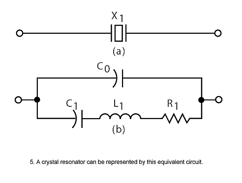
The above figure shows the equivalent circuit diagram of quartz crystal in an electronic oscillator that consists of resistor, inductor, and capacitors which are connected as shown in the figure.
Crystal Oscillator Working
The atoms, molecules, ions are packed in an order in three spatial dimensions with repeating pattern to form a solid that can be called as a crystal. The crystal can be made by almost any object that is made of elastic material by using appropriate electrical transducers. As every object consists of natural resonant frequency of vibration, steel consists of high speed of sound and is also very elastic.
Thus, steel is frequently used instead of quartz in mechanical filters. This resonant frequency depends on different parameters such as size, elasticity, speed of sound, and shape of the crystal. In general, the shape of high frequency crystals is simple rectangular plate and the shape of low frequency crystals is tuning fork shape as shown in the figure below.
Crystal oscillator circuit works on the principle of the inverse piezoelectric effect, i.e., a mechanical deformation is produced by applying an electric field across certain materials. Thus, it utilizes the vibrating crystal’s mechanical resonance which is made of a piezoelectric material for generating an electrical signal of a specific frequency.
These quartz crystal oscillators are highly stable, consists of good quality factor, they are small in size, and are very economical. Hence, quartz crystal oscillator circuits are superior compared to other resonators such as LC circuits, turning forks, and so on. Generally, 8MHz crystal oscillator is used in microprocessors and microcontrollers.
The equivalent electrical circuit also represents the crystal action of the crystal. The basic components used in the circuit, inductance L1 represent crystal mass, capacitance C1 represents compliance, resistance R1 represents the crystal’s internal structure friction, and C0 is used to represent the capacitance that is formed because of crystal’s mechanical moulding.
The quartz crystal oscillator circuit diagram consists of series resonance and parallel resonance, i.e., two resonant frequencies. If the reactance produced by capacitance C1 is equal and opposite to the reactance produced by inductance L1, then the series resonance occurs. The series and parallel resonant frequencies are represented by fs and fp respectively, and the values of fs and fp can be determined by using the following equations shown in the figure below.
Thus, the impedance is approximately equal to the resistance R1 during this condition. If the series resonant leg reactance is equal to the reactance caused due to capacitance C0, then parallel resonance occurs. Thus, the external circuit if offered a very high impedance by the crystal during this condition.
The above figure shows the graph between impedance and frequency of the quartz crystal oscillator circuit. Typically, crystal oscillators are having a frequency range from 32KHz to 200MHz.
Use of Crystal Oscillator
In general, we know that, crystal oscillators are used in the microprocessors and microcontrollers for providing the clock signals. Let us consider 8051 microcontroller for which an external crystal oscillator circuit of 12MHz is essential, even though (based on model) 8051 microcontroller is capable to run at 40 MHz (max). 8051 requires 12 clock cycles for one machine cycle, such that to give effective cycle rate at 1MHz (considering 12MHz clock) to 3.33MHz (considering maximum 40MHz clock). This crystal oscillator is used to generate clock pulses required for the synchronization of all the internal operations.
There are numerous applications for crystal oscillator in various fields and a few crystal oscillator applications are shown below:
Application of Crystal Oscillator in Military and Aerospace
The use of crystal oscillator in military and aerospace, is to establish an efficient communication system, for the navigation purpose, electronic warfare, in the guidance systems, and so on.
Use of Crystal Oscillator in Research and Measurement
The crystal oscillator is used in research and measurement for celestrial navigation, space tracking purpose, in the measuring instruments and medical devices, and so on.
Industrial Applications of Crystal Oscillator
There are a huge number of industrial applications of crystal oscillator such as in computers, digital systems, instrumentation, phase locked loop systems, marine, modems, sensors, telecommunications, disk drives, and so on.
Use of Crystal Oscillator in Automotive
Crystal oscillator is used for engine controlling, stereo, clock and to trip computer, and in GPS system.
Consumer Applications of Crystal Oscillator
Crystal oscillators are used in many consumer goods such as cable television systems, personal computers, video cameras, toys and video games, radio systems, cellular phones, and so on .
Inside a Crystal Oscillator
A crystal oscillator is an electronic oscillator circuit which uses inverse piezoelectric effect, ie when electric field is applied across certain materials it produces mechanical deformation. Thus it uses mechanical resonance of a vibrating crystal of piezoelectric materiel to create an electric signal with very precise frequency. They have high stability, quality factor, small size and low cost and this makes them superior over other resonators like LC circuit, ceramic resonator, turning forks etc.
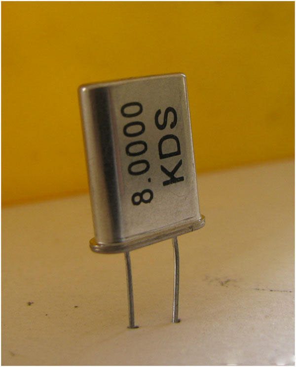
This image show a 8MHz crystal oscillator commonly used in microcontrollers and microprocessors. Although the crystal has electromechanical resonance, we can represent the crystal action by an equivalent electrical resonant circuit as show below. The inductance and capacitance L1 and C1 represents electrical equivalents of crystal mass and compliance, while the resistance R1 represents the friction of crystal’s internal structure and C0 represents the capacitance formed due to mechanical moulding of the crystal.
From the circuit we can find that it can have two resonant frequencies, series resonance and parallel resonance. Series resonance occurs when the reactances produced by capacitance C1 and inductance L1 becomes equal and opposite. Thus during this condition impedance is very low, equal to resistance R1. Parallel resonance occurs when the reactance of series resonant leg becomes equal to reactance produced by capacitance C0. During this condition the crystal offers very high impedance to the external circuit.
Impedance versus frequency graph is shown below…..
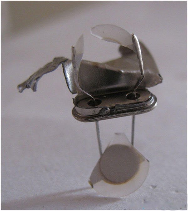
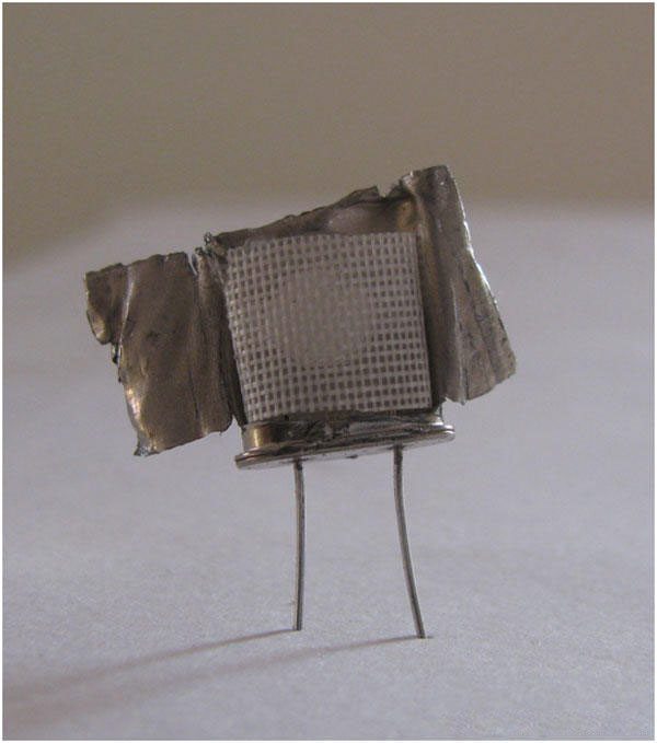
The entire crystal is covered with metal casing as shown in the image.
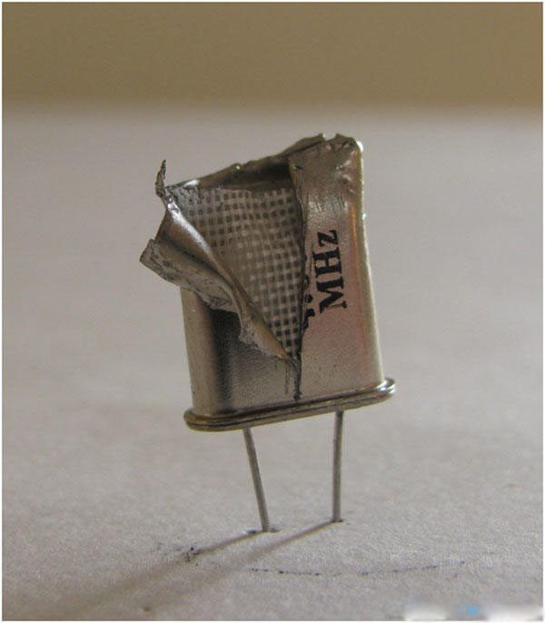
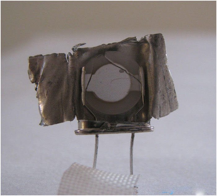
On removing this metal casing we can see a net like blanket to protect crystal from mechanical damages.
In the above image we can see the net casing inside the outer metal casing and crystal is placed inside it.
Electronic oscillator
An electronic oscillator is an electronic circuit that produces a periodic, oscillating electronic signal, often a sine wave or a square wave. Oscillators convert direct current (DC) from a power supply to an alternating current (AC) signal. They are widely used in many electronic devices. Common examples of signals generated by oscillators include signals broadcast by radio and television transmitters, clock signals that regulate computers and quartz clocks, and the sounds produced by electronic beepers and video games.
Oscillators are often characterized by the frequency of their output signal:
- A low-frequency oscillator (LFO) is an electronic oscillator that generates a frequency below approximately 20 Hz. This term is typically used in the field of audio synthesizers, to distinguish it from an audio frequency oscillator.
- An audio oscillator produces frequencies in the audio range, about 16 Hz to 20 kHz.
- An RF oscillator produces signals in the radio frequency (RF) range of about 100 kHz to 100 GHz.
Oscillators designed to produce a high-power AC output from a DC supply are usually called inverters.
There are two main types of electronic oscillator – the linear or harmonic oscillator and the nonlinear or relaxation oscillator .
In electronics a relaxation oscillator is a nonlinear electronic oscillator circuit that produces a nonsinusoidal repetitive output signal, such as a triangle wave or square wave. The circuit consists of a feedback loop containing a switching device such as a transistor, comparator, relay, op amp, or a negative resistance device like a tunnel diode, that repetitively charges a capacitor or inductor through a resistance until it reaches a threshold level, then discharges it again. The period of the oscillator depends on the time constant of the capacitor or inductor circuit. The active device switches abruptly between charging and discharging modes, and thus produces a discontinuously changing repetitive waveform. This contrasts with the other type of electronic oscillator, the harmonic or linear oscillator, which uses an amplifier with feedback to excite resonant oscillations in a resonator, producing a sine wave. Relaxation oscillators are used to produce low frequency signals for applications such as blinking lights and electronic beepers and in voltage controlled oscillators (VCOs), inverters and switching power supplies, dual-slope analog to digital converters, and function generators.

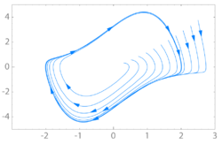
The term relaxation oscillator is also applied to dynamical systems in many diverse areas of science that produce nonlinear oscillations and can be analyzed using the same mathematical model as electronic relaxation oscillators. For example, geothermal geysers, networks of firing nerve cells, thermostat controlled heating systems, coupled chemical reactions, the beating human heart, earthquakes, the squeaking of chalk on a blackboard, the cyclic populations of predator and prey animals, and gene activation systems have been modeled as relaxation oscillators. Relaxation oscillations are characterized by two alternating processes on different time scales: a long relaxation period during which the system approaches an equilibrium point, alternating with a short impulsive period in which the equilibrium point shifts. The period of a relaxation oscillator is mainly determined by the relaxation time constant. Relaxation oscillations are a type of limit cycle and are studied in nonlinear control theory .
Relaxation oscillators are generally used to produce low frequency signals for such applications as blinking lights, and electronic beepers. and clock signals in some digital circuits. During the vacuum tube era they were used as oscillators in electronic organs and horizontal deflection circuits and time bases for CRT oscilloscopes; one of the most common was the Miller integrator circuit invented by Alan Blumlein, which used vacuum tubes as a constant current source to produce a very linear ramp. They are also used in voltage controlled oscillators (VCOs), inverters and switching power supplies, dual-slope analog to digital converters, and in function generators to produce square and triangle waves. Relaxation oscillators are widely used because they are easier to design than linear oscillators, are easier to fabricate on integrated circuit chips because they do not require inductors like LC oscillators, and can be tuned over a wide frequency range. However they have more phase noise and poorer frequency stability than linear oscillators. Before the advent of microelectronics, simple relaxation oscillators often used a negative resistance device with hysteresis such as a thyratron tube, neon lamp, or unijunction transistor, however today they are more often built with dedicated integrated circuits such as the 555 timer chip.
General concept
The system is in unstable equilibrium if both the inputs and outputs of the comparator are at zero volts. The moment any sort of noise, be it thermal or electromagnetic noise brings the output of the comparator above zero (the case of the comparator output going below zero is also possible, and a similar argument to what follows applies), the positive feedback in the comparator results in the output of the comparator saturating at the positive rail.
In other words, because the output of the comparator is now positive, the non-inverting input to the comparator is also positive, and continues to increase as the output increases, due to the voltage divider. After a short time, the output of the comparator is the positive voltage rail, .
The inverting input and the output of the comparator are linked by a series RC circuit. Because of this, the inverting input of the comparator asymptotically approaches the comparator output voltage with a time constant RC. At the point where voltage at the inverting input is greater than the non-inverting input, the output of the comparator falls quickly due to positive feedback.
This is because the non-inverting input is less than the inverting input, and as the output continues to decrease, the difference between the inputs gets more and more negative. Again, the inverting input approaches the comparator's output voltage asymptotically, and the cycle repeats itself once the non-inverting input is greater than the inverting input, hence the system oscillates.
Example: Differential equation analysis of a comparator-based relaxation oscillator
Rearranging the differential equation into standard form results in the following:
Notice there are two solutions to the differential equation, the driven or particular solution and the homogeneous solution. Solving for the driven solution, observe that for this particular form, the solution is a constant. In other words, where A is a constant and .
is the sum of the particular and homogeneous solution.
Solving for B requires evaluation of the initial conditions. At time 0, and . Substituting into our previous equation,
Frequency of oscillation
First let's assume that for ease of calculation. Ignoring the initial charge up of the capacitor, which is irrelevant for calculations of the frequency, note that charges and discharges oscillate between and . For the circuit above, Vss must be less than 0. Half of the period (T) is the same as time that switches from Vdd. This occurs when V− charges up from to .
When Vss is not the inverse of Vdd we need to worry about asymmetric charge up and discharge times. Taking this into account we end up with a formula of the form:
Which reduces to the above result in the case that .
XXX . XXX 41% zero Limit cycle
In mathematics, in the study of dynamical systems with two-dimensional phase space, a limit cycle is a closed trajectory in phase space having the property that at least one other trajectory spirals into it either as time approaches infinity or as time approaches negative infinity. Such behavior is exhibited in some nonlinear systems. Limit cycles have been used to model the behavior of a great many real world oscillatory systems. The study of limit cycles was initiated by Henri Poincaré (1854–1912).
Definition
We consider a two-dimensional dynamical system of the form
where
is a smooth function. A trajectory of this system is some smooth function with values in which satisfies this differential equation. Such a trajectory is called closed (or periodic) if it is not constant but returns to its starting point, i.e. if there exists some such that for all . An orbit is the image of a trajectory, a subset of . A closed orbit, or cycle, is the image of a closed trajectory. A limit cycle is a cycle which is the limit set of some other trajectory.
Properties
By the Jordan curve theorem, every closed trajectory divides the plane into two regions, the interior and the exterior of the curve.
Given a limit cycle and a trajectory in its interior that approaches the limit cycle for time approaching , then there is a neighborhood around the limit cycle such that all trajectories in the interior that start in the neighborhood approach the limit cycle for time approaching . The corresponding statement holds for a trajectory in the interior that approaches the limit cycle for time approaching , and also for trajectories in the exterior approaching the limit cycle.
Stable, unstable and semi-stable limit cycles
In the case where all the neighbouring trajectories approach the limit cycle as time approaches infinity, it is called a stable or attractive limit cycle (ω-limit cycle). If instead all neighbouring trajectories approach it as time approaches negative infinity, then it is an unstable limit cycle (α-limit cycle). If there is a neighbouring trajectory which spirals into the limit cycle as time approaches infinity, and another one which spirals into it as time approaches negative infinity, then it is a semi-stable limit cycle. There are also limit cycles which are neither stable, unstable nor semi-stable: for instance, a neighboring trajectory may approach the limit cycle from the outside, but the inside of the limit cycle is approached by a family of other cycles (which wouldn't be limit cycles).
Stable limit cycles are examples of attractors. They imply self-sustained oscillations: the closed trajectory describes perfect periodic behavior of the system, and any small perturbation from this closed trajectory causes the system to return to it, making the system stick to the limit cycle.
Finding limit cycles
Every closed trajectory contains within its interior a stationary point of the system, i.e. a point where . The Bendixson–Dulac theorem and the Poincaré–Bendixson theorem predict the absence or existence, respectively, of limit cycles of two-dimensional nonlinear dynamical systems.
Open problems
Finding limit cycles in general is a very difficult problem. The number of limit cycles of a polynomial differential equation in the plane is the main object of the second part of Hilbert's sixteenth problem. It is unknown, for instance, whether there is any system in the plane where both components of are quadratic polynomials of the two variables, such that the system has more than 4 limit cycles.
XXX . XXX 42% zero null 24 Load Switch IC TCK301G, TCK302G, TCK303 Application & Circuit
Description
- Operation and application of the slew rate control circuitry designed for inrush current limiting
- Main switches of USB PD-enabled rapid-charging circuits for electronic devices with USB Type-C™ ports
- Main switches of 5- to 12-V power supply input circuits that support various modes of rapid charging and wireless power transfer
- Switches for the power management of systems requiring power-saving modes
Features
- Small package: 0.5 mm pitch WCSP9 ( 1.5 mm x 1.5 mm, t: 0.5 mm (Typ.)) , PD = 1.65 W
- High input voltage: VIN (Max) = 28 V
- High output current: IOUT (DC) = 3.0 A
- Low ON resistance : RON = 73 mΩ (Typ.) at VIN = 4.5 V, IOUT = - 1.0 A
- Inrush current reducing circuit ( slew rate control )
- Over voltage lockout circuit : 6.6 V at 301G, 10.5 V at 302G, and 15.5 V at 303G (Typ.)
- Under voltage lockout circuit: 2.9 V (Typ.)

Overview : The OK301 is a single chip implementation of USB security keyboard which includes key matrix controller and security fratures. It also support for 2.4G RF keyboard if integrated with OK100B RF keyboard controller. Cloud Keyboard Security is a method to resist keylogger for the Personal Computer in the Cloud Computing Internet. The OK301 embedded FIPS certificated AES engine for CKS. By the method of OK301 keyboard security controller, the keylogger can't steal user’s keystrokes with right meanings, so that the online applications are safe for any critical business transaction.
The OK301 built in an oTHE 8-bit single instruction RISC CPU with 8KByte Flash. It provides a non-conflict key-scan architecture that allows user press over 12 keys at the same time. It resolved a long time problem that USB keyboard can not press over 6 keys at the same time. This key-scan architecture also includes auto key scan change detection and ghost key cancellation. |  | ||||
|
Application : Due to personal computer hardware and software’s natural limitations, hackers can easily attach a keylogging software through a Trojan virus and access an end-user’s unprotected keystroke data. This hacking technique is so common and easy to implement that many accounts and passwords are stolen daily. If the stolen identity is a credit card number, online banking account, or any of the other numerous types of important data, a significant loss can and will be incurred. The cloud computing is booming and endorsed by almost every countries in the world. Information stored in remote servers and access from front-end devices. The keyboard is vital security equipment in the cloud computing ecosystem. oTHE has developed Cloud Keyboard Security Solution (CKSS), providing traditional keyboards with the ability to secure anything the user types, allowing users not to worry about keyloggers. CKSS is the first anti-keylogger solution by both hardware and software working together, and it is the only proactive solution for anti-keylogging, which secures the end-user data input, even in cloud computing. OK301 has passed more than 50 keylogging software tests, with the results positive and surpassing other anti-keylogging software solutions. The CKSS system core algorithm (AES algorithm) has passed American standards (NIST) in password verification with CAVP (Cryptographic Algorithm Validation Program).
The OK301 is LQFP-48Pin package for standard USB keyboard. OK301 and OK100B are also the best cost-effective wireless keyboard controller, and high security keyboard encryptor for anti-keylogger solutions. | |||||
 | |||||
 | |||||
Overview : The OK100B is a wireless Keyboard Security Controller for 2.4G RF Keyboard/Mouse dongle. Cloud Keyboard Security is a method to resist keylogger for the Personal Computer in the Cloud Computing Internet. The OK100B embedded FIPS certificated AES engine for CKS. By the method of OK100B CKS controller, the keylogger can't steal user’s keystrokes with right meanings, so that the online applications are safe for any critical business transaction.
The OK100B built in an oTHE 8-bit single instruction RISC CPU with 8KByte Flash only. It provides USB 2.0 interface and supports USB 1.1 protocol. The OK100B supports TQFN-24Pin package for standard 2.4G keyboard dongle. It is very easy to integrate into existing normal 2.4G RF keyboard, even does not need modify the firmware of Device(Keyboard). |  | ||||
|
Application : Due to personal computer hardware and software’s natural limitations, hackers can easily attach a keylogging software through a Trojan virus and access an end-user’s unprotected keystroke data. This hacking technique is so common and easy to implement that many accounts and passwords are stolen daily. If the stolen identity is a credit card number, online banking account, or any of the other numerous types of important data, a significant loss can and will be incurred. oTHE Cloud Keyboard Security Solution (CKSS) is the best keyboard security solution now, guarding your keystrokes for online banking, shopping, gaming, and many others. oTHE launched Cloud Keyboard Security Solution to not only integrate itself in current local applications but also in cloud computing applications. CKSS is the first anti-keylogger solution by both hardware and software working together, and it is the only proactive solution for anti-keylogging, which secures the end-user data input, even in cloud computing. It has passed more than 50 keylogging software tests, with the results positive and surpassing other anti-keylogging software solutions. The CKSS system core algorithm (AES algorithm) has acquired the FIPS Certification in CAVP (Cryptographic Algorithm Validation Program).
The OK100B keyboard security chip is a TQFN-24pin chip package that can be built within the 2.4G RF dongle. It is a single chip replacement in the dongle, and there is no need to modify the device (keyboard) hardware and software, automatically bringing you security from within the wireless keyboard. | |||||
 | |||||
Overview : OK100 is a keyboard security controller. It contains 8-Bit MCU, encryption calculator, 8K Bytes Flash, SRAM, USB 1.1 controller and PS2 controller circuit. OK100 and software through the integration of encryption technology, can take the initiative to prevention network hackers or other malicious software(Keylogger) to steal personal information. OK100 is a SOIC-16Pin package can be built within the PC keyboard, made USB/PS2 Adapter, or built within the motherboard. It can be resolved when the user concerns in the Internet, and was be-logged happens. It is a low-cost, high security encryption and practical solutions.
|  | ||||
|
Application : Due to personal computer hardware and software nature limitations, the hacker attacked this leakage through keylogger software by Trojan virus and hooked the keystrokes data. The hacker technique is so common and easy to spread that account and password was stolen all the time. If the keystrokes data is credit card number, online banking ID and password, or other important data, the actual loss may caused. OK100 is the best solution now, it can guard your keystrokes data for online banking, shopping, gaming..ect. oTHE launched Cloud Keyboard Security not only apply in current application but also in cloud computing application. OK100 is the first anti-keylogger solution by hardware and software together and it is the only proactive solution for anti-keylogger which can secure the end-user data input in cloud computing. OK100 has passed more than 50 keyboard logging software (Keylogger) test, all the testing result is positive. Compare to other anti-keylogger software solution, OK100 is better choice, no doubt definitely. The OK100 Cloud Keyboard Security also won third place in the Buyers' Choice product awards at the 2010 Taipei International Computer Show (Computex 2010). The AES's core algorithm of OK100 was also certificated by CAVP( Cryptographic Algorithm Validation Program ) of NIST( National Institute of Standards and Technology ) in February of this year.
OK100 keyboard security is a SOIC-16Pin-chip package can be built within the PC keyboard, made USB/PS2 Adapter, or built within the motherboard. | |||||
 | |||||
Overview : The OK106 is a Keyboard Security Controller for smart phone which used to link your smart phone to Notebook PC's USB port. It supports "AccountPal" APP to protect your keystroke data, and prevent network hackers or other malicious software(Keylogger) to steal personal information. AccountPal APP is a keystroke data protector. This APP is an application of iPhone and it emulate a keyboard for normal Desk-top PC or Notebook data input. To execute this APP and connect an OK106 Security Cable” when you like to key-in important data, such like : ID number, Password, Banking Account or Credit Card number for data input into PC or notebook, then the keystroke data which through this APP of iPhone will be protected and prevent keylogging from spyware (keylogger) in the PC or notebook.
The OK106 built in an oTHE 8-bit single instruction RISC CPU, AES Security Engine, 64KBytes Flash, SRAM and PS2 controller circuit. It also provides USB 2.0 interface and supports USB 1.1 protocol. The OK106 is a TQFN-24Pin or LQFP-48Pin package. | |||||
| |||||
Application : Due to personal computer hardware and software’s natural limitations, hackers can easily attach a keylogging software through a Trojan virus and access an end-user’s unprotected keystroke data. This hacking technique is so common and easy to implement that many accounts and passwords are stolen daily. If the stolen identity is a credit card number, online banking account, or any of the other numerous types of important data, a significant loss can and will be incurred. The cloud computing is booming and endorsed by almost every countries in the world. Information stored in remote servers and access from front-end devices. The keyboard is vital security equipment in the cloud computing ecosystem. oTHE has developed Cloud Keyboard Security Solution (CKSS), providing traditional keyboards with the ability to secure anything the user types, allowing users not to worry about keyloggers. CKSS is the first anti-keylogger solution by both hardware and software working together, and it is the only proactive solution for anti-keylogging, which secures the end-user data input, even in cloud computing. OK106 has passed more than 50 keylogging software tests, with the results positive and surpassing other anti-keylogging software solutions. The CKSS system core algorithm (AES algorithm) has passed American standards (NIST) in password verification with CAVP (Cryptographic Algorithm Validation Program).
The following diagram shows an example application of OK106. You can develop a keypad APP of smart phone, and then connect a security cable which integrated OK106 controller to your PC, to protect your important keystroke data. | |||||
 | |||||
Overview : The OK102 is a USB keyboard security controller. It will be easier to upgrade your current USB wired/wireless keyboard to SECURITY wired/wireless keyboard within OK102 chip and Cloud Keyboard Security software. OK102 will encrypt your every keystroke especailly your confidential user name and password, so that the hacker will only get the incorrect and encrypted code. So you don’t worry about your important inforamtion stolen especially when online gaming, online banking, online shopping or instant messenger.
It contains 16-Bit MCU, encryption calculator, USB Host / Slave controller, 256K Bytes Flash and 16K Bytes SRAM. OK102 and Cloud Keyboard Security (CKS) software through the integration of encryption technology, can take the initiative to prevention network hackers or other malicious keylogger software to steal personal information. |  | ||||
|
Application : OK102 keyboard security IC not only has OK100/OK300 Cipher but also integrates the more complete USB Host / Device controller. At the same time, oTHE developed its own very simple and high efficiency 16-bit CPU as the core of the controller, so you can enjoy high security, practicality and low cost keyboard encryption upgrade solution. Due to the limitation of PC software and hardware – the hackers can easilly install keylooger by many forms, as emails, viruses, Trojan horses then to record everything you type on the computer, including documents, emails, user names and passwords, and then either store these information in a hidden place on your computer or send it over the Internet to the person who infiltrated it. Since the Internet has become a part of daily life and business like online gaming, online banking, online shopping , rapid growth of cybercrime endangers the whole society, for example, saving account or credit card number or other confidential datas stolen. So, the keyboard is a very important inforamtion security equipment. That’s why oTHE develops the Cloud Keyboard Security Controller and Software to make the traditional keybaord to become the security keyboard. Currently, OK102 adopts 128-bit AES encryption, which has been approval by CAVP of NIST and also pass more than 50 keylogger programs. Easy to use and reliable, OK102 helps to protect your privacy and make sure that all your confidental inforamtion remains secret and safety.
OK102 is a LQFP-32Pin package can be built in a USB adapter, or built within the motherboard. It can be resolved when the user concerns in the Internet, and was be-logged happens. It is a low-cost, high security encryption and practical solutions for hardware anti-keylogger. | |||||
 | |||||
attention : A microprocessor belongs to the family of integrated circuits; it has many transistors forming many gates and logic functions to be a processor.
An integrated circuit can be a collection of many transistors arranged to do many functions besides processing. It can be digital or analog or even mixed. within digital and analog functions there can be thousands of applications.
In other words a microprocessor is always an integrated circuit, but an integrated circuit doesn't have to be a microprocessor.
A microprocessor is an integrated circuit. Not all integrated circuits are microprocessors.
An integrated circuit is simply an electronic device where all its functional blocks - transistors, etc - are fabricated on the same piece of silicon.



An integrated circuit is simply an electronic device where all its functional blocks - transistors, etc - are fabricated on the same piece of silicon.
Integrated Circuit (IC) can be a memory chip, configuration chip. logic chip or microprocessor chip, The difference of the last one is it is the brain that process all data taken from the other 3 chips.

XXX . XXX 44% zero null 46 System selection considerations : CENTRAL PROCESSOR
CENTRAL PROCESSOR
The heart of the syscon is invariably a microprocessor. A 4-bit type is most usual, with on-board ROM containing an instruction set appropriate to the videorecorder design and deck members. Very often this ROM is permanently programmed by or at the request of the equipment manufacturer to suit his design, the rest of the micro being of a standardised type; this ROM programme is defined by the suffix of the type number, very important when the device is replaced in a repair situation. Increasingly, microprocessors are being custom-designed for specific videorecorder or camcorder applications, particularly where the equipment manufacturer is also in the business of designing and producing ICs. This approach greatly simplifies the interfacing circuits between the syscon and its peripheral devices such as keyboards, remote control systems, motors and solenoids. It also permits the use of a single micro for all ‘intelligent’ operations within a budget-priced machine, in which timer, clock, display drive, servo and tape counter operations may be dealt with inside the same package as the syscon process itself, reducing cost, complexity, interconnection links and component count.
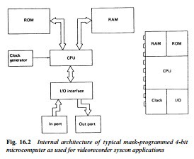
A small RAM capacity is also provided on board the μP chip to store user instructions and deck status data pending decisions or execution. Unlike conventional computing systems where memories, interfaces and codes are separate from the CPU, the one-chip microcomputer used here contains parallel processing CPU, ROM, RAM, I/O ports, programmable timer, control circuit and clock oscil- lator, see Fig. 16.2. Typical ROM and RAM capacities in a syscon microchip are 3000 × 8 bits and 96 × 8 bits respectively. No great speed in operation is required, especially as the micro spends virtu- ally all its time waiting instructions – a clock oscillator rate of 400 kHz is typical, with an instruction cycle of 10 μs.
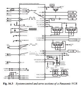
A block diagram of a typical syscon circuit, also incorporating the servo section, is shown in Fig. 16.3. There is little point in attempt- ing to indicate the internal blocks of the microprocessor section; these
devices have to be regarded as ‘black boxes’, and their internal workings are inaccessible anyway. Leaving out the servo section, dealt with in the last chapter, we start at the bottom left-hand corner with chip pins 115/6/7. Normally held high by the adjacent pull-up resistors, these three lines are selectively and sequentially grounded by the wiper contacts of the deck-mounted mode switch to indicate to the syscon the state of the deck mechanics. In this particular design the deck mechanics (see Chapter 18) are driven by a loading motor, here com- manded – via a drive IC – by syscon chip pins 11 and 12.
The other functions which concern us here are operated by the pins in the lower right-hand side of the diagram. IC pin 20 is held low when the safety tab switch S6001 is closed in the presence of a pre- recorded cassette whose tab has been knocked out: this inhibits record mode. IC pin 108 pulses the tape-end sensor LED D6001 which is mounted at the front centre of the cassette shell; when the tape is
fully rewound its light falls on phototransistor Q6002, pulsing down IC pin 94 to inhibit rewind when in stop mode or to invoke stop mode at the end of tape rewinding. Similarly the supply phototransistor Q6003, mounted on the left side of the cassette cradle, sees pulsed IR light from D6001 when the tape is fully wound on to the take-up spool (tape end condition) and signals the fact to IC pin 95 by pulsing it low. Now all forward modes are inhibited and stop or auto-rewind mode entered. When the tape is at an intermediate posi- tion the photosensor transistors are high impedance, the pull-up resistors hold chip pins 94 and 95 high, and any function is permitted.
The reel sensors here are optocoupled types, with the light from the emitter LED in each of IC 6002/6003 being alternately passed to, and blocked from, its phototransistor by castellations on the spool turntable, several times per revolution. The squarewaves thus generated pass into the IC on pins 70 and 71, where they are used not only for deck ‘emergency’ monitoring as described earlier, but to deceler- ate the tape as it approaches rewind-end; and to calculate and display tape time elapsed or remaining. This function is separate from the real-time counter, operated by the CTL pulses at chip pins 82/83.
As the pin-count of this IC suggests (it’s a 124-lead flatpack) it has many functions in addition .
XXX . XXX 45% zero null 54 Smart Analog ICS 501
Smart Analog for General-purpose instrumentation amplifier
Smart Analog IC301
Smart Analog for Low voltage general-purpose instrumentation amplifier

Startup Time
The definition for the startup time of a crystal oscillator can vary, depending on the type of system. For a microprocessor system, the startup time is often the time from initial power application to the time a stable clock signal is available. The startup time for a phase-locked loop (PLL) is often the time from initial power application to when a stable reference signal is available, often settled to within an acceptable frequency offset from the final steady state oscillation frequency. The startup time of a crystal oscillator is determined by the noise or transient conditions at turn-on; small-signal envelope expansion due to negative resistance; and large-signal amplitude limiting.
Envelope expansion is a function only of total negative resistance and the motional inductance of the crystal. The simplified equivalent series LCR circuit contains the motional inductance, the sum of the applied negative resistance of the three-point oscillator and the motional resistance of the crystal, and the effective series capacitance of the entire network (dominated by the motional capacitance). The undriven network can be modeled with:
s*L + R + 1/(s*C) = 0
Multiplying both sides by s/L gives:
s2 + s*(R/L) + 1/(L*C) = 0
The roots are located at:
½ * {–R/L ± √[(R/L)2 – 4/(L*C)]}
Because the R/L term within the square root is swamped by the 1/(L*C) term, the equation can be simplified to
–R/(2*L) ± – j * √[1/(L*C)]
Because the net resistance R is negative, the poles are in the right half-plane. The resulting time-domain solution for this differential equation is:
V(t) = K * [e|(R/2*L)|*t] * sin{2Πt√[1/(L*C)] + Θ}
where K is a constant and Θ is an arbitrary phase, both related to the initial startup conditions. The exponential expansion is valid only for small-signal conditions, as the power available to the circuit is limited.
The time constant for envelope expansion is positive. It is directly proportional to the net negative resistance of the three-point oscillator and the motional resistance, and inversely proportional to the motional inductance. Due to the large motional inductance of crystals and the limited net negative resistance, crystal oscillators have long startup times.
As an example of the envelope expansion time constant, assume a crystal with 5-fF motional capacitance, and an oscillator with 1500-Ω negative resistance, operating at 10 MHz. From the motional capacitance and operating frequency, a motional inductance of 50.7 mH can be calculated using L = 1/(C*ω2). This motional inductance yields an envelope expansion time constant of t = 2*L/|R| = 67.55 µs.
There is a tradeoff between reduced frequency pulling (due to low motional capacitance) and longer startup times (due to high motional inductance), because high motional inductance is a result of low motional capacitance. (The product of the two is more or less fixed.) This interdependence is partly mitigated by the fact that smaller motional capacitances are associated with smaller shunt capacitances, which yield larger negative resistances and thereby improve startup time.
Startup time is an important consideration in battery-powered applications where the device is often switched on and off. Shorter oscillator startup times reduce wasted energy in low-power radio systems (such as those using the MAX7032 transceiver, and the MAX1472 or MAX7058 transmitter).
Frequency Stability Versus Temperature
All crystals vary in resonant frequency as the temperature changes. The way the frequency varies depends on the angle at which the crystal is cut. The relative frequency shift versus temperature of AT-cut quartz crystals can be represented as a cubic polynomial.
Δf/f0 = A0 + A1(T – T0) + A2(T – T0)2 + A3(T – T0)3
where the coefficients A0 through A3 are functions of the cutting angle.
Frequency stability is important in systems using a crystal as the frequency reference. This is especially true for high-frequency narrow-band applications. Consider a 25 kHz channel in the 863- to 870-MHz European ISM band. A frequency drift of only 5 kHz (less than 6 ppm) could result in communication failure or regulatory noncompliance.
Keeping the drift to substantially less than 6 ppm over the “industrial-spec” temperature range of –40°C to 85°C is essentially impossible, even with zero-tolerance crystals that are perfectly cut and don’t age . In this case, a radio system with an internal temperature sensor and narrow-frequency-step fractional-N synthesizer, such as the MAX7049 transmitter, can be used to compensate for known temperature shifts.

++++++++++++++++++++++++++++++++++++++++++++++++++++++++++++++++++++++++
ELECTRONICS SWITCH ( Short Wave Interaction To Couple Highway ) SO DO
RELAXATION LIMIT SWITCH TIME
Appropriately cut quartz crystals can be used as high-quality electromechanical resonators. Their piezoelectric properties (voltage across the crystal deforms it; deforming the crystal generates a voltage) allow them to be the frequency-determining element in electronic circuits. Crystals are widely used in oscillators, time bases, and frequency synthesizers for their high quality factor (QF) ; excellent frequency stability ; tight production tolerances; and relatively low cost.

+++++++++++++++++++++++++++++++++++++++++++++++++++++++++++++++++++++++++++++++++++++++++++++++++





![T=(RC)\left[\ln \left({\frac {2V_{{ss}}-V_{{dd}}}{V_{{ss}}}}\right)+\ln \left({\frac {2V_{{dd}}-V_{{ss}}}{V_{{dd}}}}\right)\right]](https://wikimedia.org/api/rest_v1/media/math/render/svg/8cf1100fb40fec42584ef8e7a769d4902e584ae2)





Thanks For sharing very helpful information
BalasHapusVibrating Fork Level Switch for Solids
Really thanks for sharing this useful post for electronic switch mode .
BalasHapusTechbasha