
Human Sensors
- 1. HOW DO HUMAN SENSORS WORK?- UNDERSTANDING HUMAN SENSORSAND COMPARING THEM WITH THOSE IN A ROBOT (50 MINUTES)
- 2. PRE/POST- ASSESSMENT SHEET HOW DO HUMAN SENSORS WORK? 1. What sensors or senses do we humans have? 2. Describe how any two of the sensors you listed above work. 3. Give examples of sensors in robots that are similar to human senses. 2Computational Neurobiology Center, University of Missouri
- 3. PRE/POST- ASSESSMENT SHEET HOW DO HUMAN SENSORS WORK? 1. What sensors or senses do we humans have ? Eyes, Ears, Nose, Skin, Tongue, (other sensors include temperature sensors, sensors detecting body position, balance sensors, blood acidity sensors, …) 2. Describe how any two of the sensors you listed above work. Eye – takes in light from the surroundings and relays that to nerve cells that send images to the brain Ear – takes in sound waves from air and vibrates, sending the vibrations through inner ear to hair cells that send signals to the brain Nose – particles are inhaled into the nose and nerve cells contact particles and send signals to the brain Skin- sensors all over skin are activated and send signals to the brain through nervous system Tongue- taste buds are made up of small cells that have little hairs that are activated by particles in food. These hairs send signals through nerves to the brain. 3. Give examples of sensors in robots that are similar to human senses. Eyes – light sensor, ultrasonic sensor Ear – sound sensor Skin – touch sensor 3Computational Neurobiology Center, University of Missouri
- 4. WHAT IS A SENSOR? Device that measures a physical quantity such as temperature and sends the information to a device such as a computer Two types Some detect presence of a stimulus (Type I). Can you think of an example? Some detect quantity/value of a stimulus (Type II). Example? What are the sensors that exist on the robot? What are some examples of sensors in real life? Some shoes now have sensors that can transmit the distance traveled to ipods! 4 Image1: For Source/Rights Refer to slide 27Computational Neurobiology Center, University of Missouri
- 5. WHAT IS A SENSOR? A sensor is a device that measures a physical quantity (stimulus) and transmits this measurement so that a computer, instrument, or observer can read it. Some sensors simply detect the presence of a stimulus. These are called Type I sensors. Example: A sound sensor that detects the presence of a sound. Other sensors can actually discern relative values of a stimulus. These are called Type II sensors. Example: A sound sensor that detects the number of decibels in a sound. Sensors are used in everyday objects such as garage doors that won’t shut if a kid/person is in its way – do you know how that works? Other applications that use sensors include 5 cars, airplanes, robots, and medical equipment.Computational Neurobiology Center, University of Missouri
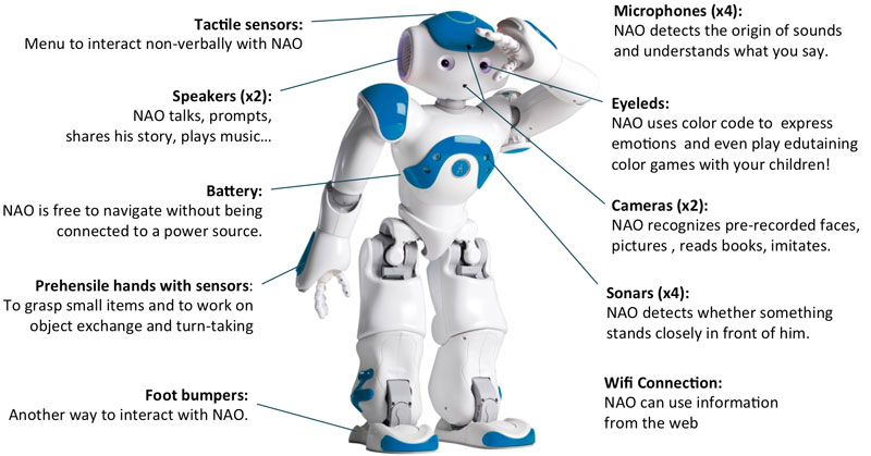
- 6. HUMAN SENSORS Your sensory organs (eyes, ears, nose and skin) provide information to your brain so that it can make decisions. They work in a manner very similar to the working of sensors of an robot. Your brain uses the information that it receives from your sensory organs continuously and make your body work. There are five senses in humans: Your eyes allow you to see the world Your ears allow you to hear sounds Your skin lets you feel objects through touch Your nose lets you smell the many scents present in the world Your tongue lets you taste …and several other sensors in the body that you don’t notice directly Sensors in the inner ear give the brain information about balance Sensors in our muscles that let the brain know our body position Sensors throughout your body that sense temperature 6 Computational Neurobiology Center, University of Missouri
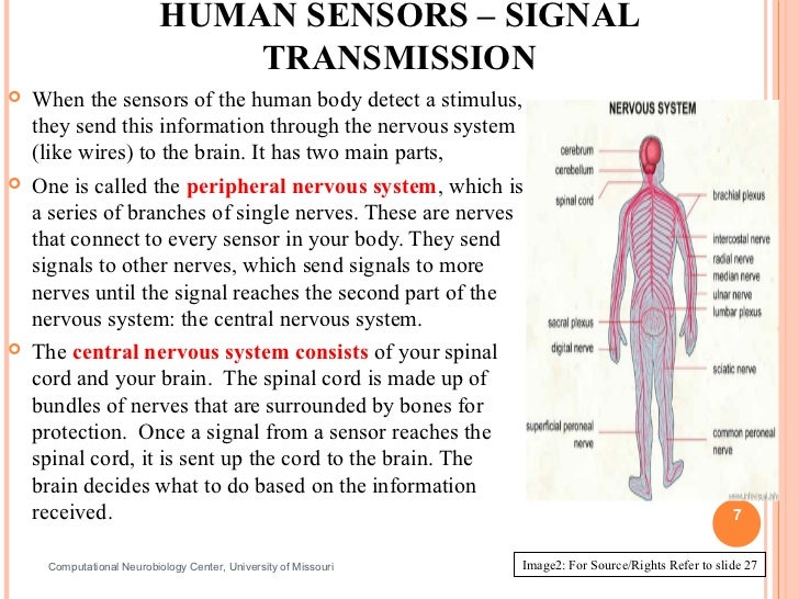
- 7. HUMAN SENSORS – SIGNAL TRANSMISSION When the sensors of the human body detect a stimulus, they send this information through the nervous system (like wires) to the brain. It has two main parts, One is called the peripheral nervous system, which is a series of branches of single nerves. These are nerves that connect to every sensor in your body. They send signals to other nerves, which send signals to more nerves until the signal reaches the second part of the nervous system: the central nervous system. The central nervous system consists of your spinal cord and your brain. The spinal cord is made up of bundles of nerves that are surrounded by bones for protection. Once a signal from a sensor reaches the spinal cord, it is sent up the cord to the brain. The brain decides what to do based on the information received. 7 Computational Neurobiology Center, University of Missouri Image2: For Source/Rights Refer to slide 27
- 8. TOUCH: HOW DO WE FEEL USING OUR SKIN? Skin contains millions of sensitive nerve endings that can detect stimuli such as Pain Pressure Temperature Many other stimuli we detect are other versions of the three above Itching is small pain stimuli Tickling is small pressure stimuli When these receptors are stimulated, they send signals through your nervous system to the brain which recognizes that something has been touched. Image3: For Source/Rights Refer to slide 27 8Computational Neurobiology Center, University of Missouri
- 9. TOUCH SENSORS ACTIVITY Activity: Each person pick a partner Each group of two should have two pencils One partner close his/her eyes and extends his/her hand to the other partner Second partner pokes the first partner’s hand with either one or two pencils, and have them guess whether one or two pencils were used. Try different distances apart when using two pencils at a time. Attempt this at various locations on the hand, starting at the palm and ending at the back of the forearm and discuss results. Switch roles. Discuss findings as a group. 9Computational Neurobiology Center, University of Missouri
- 10. VISION: HOW DOES THE BRAIN KNOW WHAT WELOOK AT? Light (stimulus) enters the eye It passes through the optic nerve Lateral Geniculate Nucleus (LGN) relays the information to the visual cortex Visual Cortex processes this information 10Computational Neurobiology Center, University of Missouri
- 11. HOW DO YOUR EYES WORK? First, light enters your eye, and is refracted, or bent, by the cornea, the outermost part of your eye. Refracted light is directed right at the pupil, a small hole in the center of the iris, the colored part of the eye. The iris can change the size of the pupil to allow more or less light to enter. Light that goes through the pupil is then redirected again by the eye’s lens, which points the light at nerve cells in the back of your eye. There are two types of nerve cells in the back: Cones detect colors and fine details in good light. They are concentrated in the center of the back part of your eye. Rods detect the presence of objects in bad light and are concentrated on the sides of the back part of your eye. Cones and rod send signal through the optic nerve to brain. 11Computational Neurobiology Center, University of Missouri
- 12. VARIOUS PARTS OF THE HUMAN EYE 12 Image 4: For Source/Rights Refer to slide 27 Computational Neurobiology Center, University of Missouri
- 13. WORKSHEET: LABEL COMPONENTS OF THE EYE 13Computational Neurobiology Center,University of Missouri
- 14. SOUND: HOW DOES YOUR EAR WORK? Sound waves enter the ear canal and cause the eardrum to vibrate Vibrations of the eardrum are carried through the hammer, anvil, and stirrup of the ear to a fluid-filled structure called the cochlea. Different pitches cause different parts of the fluid in the cochlea to vibrate When cochlear fluid vibrates, it moves hairs connected to nerve cells, which send signals to the brain through the auditory nerve. The brain helps you recognize the sound. Image 5: For Source/Rights Refer to slide 27 14Computational Neurobiology Center, University of Missouri
- 15. VARIOUS PARTS OF THE HUMAN EAR 15 Image 5: For Source/Rights Refer to slide 27 Computational Neurobiology Center, University of Missouri
- 16. WORKSHEET- LABEL PARTS OF THE HUMAN EAR 16Computational Neurobiology Center, University of Missouri
- 17. SMELL: HOW DO WE SMELL USING OUR NOSE? Small particles of almost everything around us can be found in the air. These particles enter the nose when you breathe in and contact nerve endings in the upper nasal passage. These nerve endings send a signal through the nervous system to the brain, which makes sense of the smell. Humans can distinguish between hundreds of different smells. Dogs can distinguish between thousands. Image 6: For Source/Rights Refer to slide 27 17http://videos.howstuffworks.com/howstuffworks/461-how-smell-works-video.htm Computational Neurobiology Center, University of Missouri
- 18. TASTE: HOW DO WE TASTE USING OUR TONGUE? The tongue has sensory receptors called taste buds that can detect one of five different flavors Sweet Salty Bitter Sour Umami Umami is a flavor that is said to be present in many high-protein foods, such as meats, cheeses, tomatoes and mushrooms, and is generally described as being a savory, meaty taste. Taste buds are comprised of cells called gustatory receptor cells. These cells have tiny hairs that detect taste from the food that you eat. The hairs send information to the cells, which send a signal through the nervous system to the brain, which interprets the information as taste. What is the difference between taste and flavor? Flavor includes taste, but also a little more. It comprises taste, smell, texture of food, and even other sensations such as pain when you eat something spicy. Eating food with your nose blocked shows a marked 18 decrease in flavor, even though the taste is the same. Computational Neurobiology Center, University of Missouri Image 7: For Source/Rights Refer to slide 27
- 19. TASTE ACTIVITY Activity requiring Starburst (or other) flavored candy: Pair students in groups of two Each student get two pieces of Starburst candy - the other student should not know the flavors that his/her partner has. One partner should close his/her eyes and close his/her nose while the other partner unwraps and gives him/her one piece of candy. The taster should then guess the flavor of the candy. Then, the taster should wipe their tongue dry with a paper towel, close their eyes, and be given the other piece of candy and guess its flavor. Switch roles. Discuss findings as a group after all the groups are done. 19Computational Neurobiology Center, University of Missouri
- 20. NXT ROBOT SENSORS What do they do? Gather information from the surroundings and send it to the computer brick. Robot Sensors can only be used if the Robot’s program asks for information from them! Similarly, the Robot can only act on information from the sensors if its program tells it to do so! How do sensors send signals to the Computer brick? The sensors send information through the wires (similar to the nervous system in your body) that connect them to the Computer brick, which uses the information if its program requires it. 20Computational Neurobiology Center, University of Missouri
- 21. HOW DO ROBOT SENSORSWORK? Touch Sensor Button-like protrusion. When bumped, it sends a signal to the computer brick saying that it has been touched Light Sensor Works in two different ways Can detect the amount of ambient light and convert it to a numerical value. This value is sent to the Computer brick Can send out light and detect how much is reflected by an object. This is to detect brightness of an object. Converts amount of reflected light to a numerical value and sends it to the Computer brick. If no object is in front of the sensor, it sends a value of zero. 21Computational Neurobiology Center, University of Missouri
- 22. HOW DO ROBOT SENSORS WORK?(CONT.) Sound Sensor What is Sound? Sound is made up of sound waves or vibrations in the air. Louder sounds produce larger vibrations Higher pitch sounds produce more frequent vibrations Sound sensor has a thin piece of material called a diaphragm that vibrates when hit by sound waves (similar to your eardrum). If vibrations of the diaphragm are large enough to be detected, the sound sensor sends a signal to the Computer brick saying that it has heard a sound. 22Computational Neurobiology Center, University of Missouri
- 23. HOW DO ROBOT SENSORS WORK? (CONT.) Ultrasonic Sensor The Ultrasonic Sensor has two parts A transmitter that sends out a signal that humans cannot hear A receiver that receives the signal after it has bounced off of nearby objects The sensors sends out its signal and determines how long the signal takes to come back. If the object is very close to the sensor, the signal will come back quickly If the object is far away from the sensor, the signal takes longer to come back If objects are too far away from the sensor, the signal will take so long to come back (or be so weak when it comes back) that the receiver cannot detect it The Ultrasonic Sensor sends a message back to the computer brick, telling it the time taken for the signal to return. The computer brick then uses this information to compute how far away the object was. Can you name a process performed by certain animals that works like this? 23 Computational Neurobiology Center, University of Missouri
- 24. WHAT ARE ROBOT EQUIVALENTS OF HUMAN SENSORS? 24Computational Neurobiology Center, University of Missouri
- 25. PRE/POST- ASSESSMENT SHEET HOW DO HUMAN SENSORS WORK? 1. What sensors or senses do we humans have? 2. Describe how any two of the sensors you listed above work. 3. Give examples of sensors in robots that are similar to human senses. 25Computational Neurobiology Center, University of Missouri
- 26. PRE/POST- ASSESSMENT SHEET HOW DO HUMAN SENSORS WORK? 1. What sensors or senses do we humans have ? Eyes, Ears, Nose, Skin, Tongue, (other sensors include temperature sensors, sensors detecting body position, balance sensors, blood acidity sensors, …) 2. Describe how any two of the sensors you listed above work. Eye – takes in light from the surroundings and relays that to nerve cells that send images to the brain Ear – takes in sound waves from air and vibrates, sending the vibrations through inner ear to hair cells that send signals to the brain Nose – particles are inhaled into the nose and nerve cells contact particles and send signals to the brain Skin- sensors all over skin are activated and send signals to the brain through nervous system Tongue- taste buds are made up of small cells that have little hairs that are activated by particles in food. These hairs send signals through nerves to the brain. 3. Give examples of sensors in robots that are similar to human senses. Eyes – light sensor, ultrasonic sensor Ear – sound sensor Skin – touch sensor 26Computational Neurobiology Center, University of Missouri
- 27. IMAGE SOURCE/RIGHTSImage 1:ADA Description: Shoe with ipod embedded in it.Image file name: shoe designSource/Rights: http://www.gadgetsharp.com/20091123/9-creative-and-high-tech-shoes-designs/Image 2:ADA Description: Human Nervous System.Image file name: Nervous SystemSource/Rights: http://www.infovisual.info/03/038_en.htmlImage 3:ADA Description: Nerves in human hand.Image file name: battery.jifSource/Rights: static.howstuffworks.com/gif/battery.gifImage 4:ADA Description: Human Eye.Image file name: Human eye.jpgSource/Rights: http://www.ratbehavior.org/Eyes.htmImage 5:ADA Description: Human Ear anatomy.Image file name: HumanEar.jpgSource/Rights: www.commons.wikimedia.org 27Computational Neurobiology Center,College of Engineering, University ofMissouri, Columbia MO 65211
- 28. IMAGE SOURCE/RIGHTS Image
Robo Classification by Application
Robos can be classified by components such as their type of locomotion or kinematics. This approach works very well when only industrial robots are being classified. As robos have become more ubiquitous and complex this component centered system of classification has become less relevant to the general study of robotics. This lesson will focus on classifying robos by their application.
Objectives
1) The student will be able to classify robots by application.
2) The student will be able to discuss specific functions of specific robos.
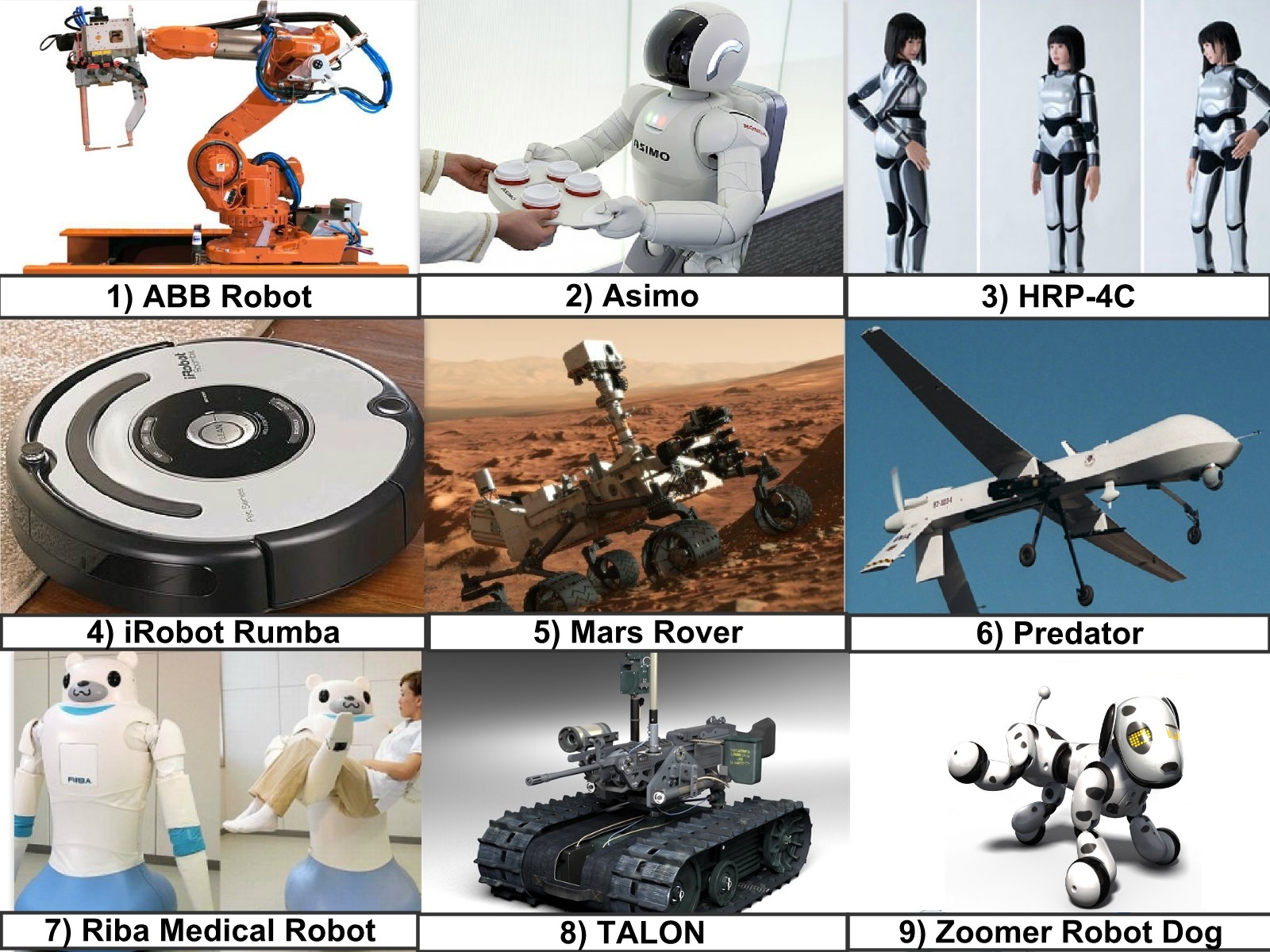
1) Industrial robo – ABB Robo

2) Humanoid robo

4) Humanoid robot – HRP-4C
6) Military robo– Predator


6) Military robot – Predator
7) Medical robot – Riba

8) Military robot – TALON

9) Toy robo – Zoomer
X . I

Sensor to help robots read human expressions
A team of researchers here has created a stretchable and transparent sensor that could help robos read human facial expressions -- from smiling and frowning to brow-furrowing and eye-rolling.
developed the ultra-sensitive and wearable sensor by layering a carbon nanotube film on two different kinds of electrically-conductive elastomers.
They found it could tell whether people were laughing or crying and where they were looking.The new sensor detect facial movements, including slight changes in gaze.
"One way to make interactions between people and robots more intuitive would be to endow machines with the ability to read their users' emotions and respond with a computer version of empathy," Lee added.
The technology, reported in the journal ACS Nano, can help robot developers make their machines more human.


Build an Obstacle-Avoiding Robo

Robo Architectures
of the motors, the avoid module suppresses the output of the runaway module. The combined Level 0 and Level 1 behavior result in a robot that wanders aimless about but avoid obstacles.
Robo Architectures
In 1990 when entitled "Integrated Planning and Execution", I didn't have a lot to say about "Architectures" or "Robot Programming Languages" and indeed I don't have a great deal more to say now. However, given the amount of time and effort spent by some of my colleagues on the subject, I want to provide at least a glimpse of what all the excitement is about. My lack of enthusiasm doesn't reflect on the problem, the problem is both interesting and challenging, so much as on my dissatisfaction with the current solutions.What is it that distinguishes the software for a reasonably sophisticated robot from most other large and complicated software systems? The answer has to do with its embededness of the robot and the demands of responding to the environment in a timely manner. The relationship between the computational requirements for coming up with an an appropriate response to a given environmental challenge and the time allowed by the circumstances is at the heart of designing robot architectures. In many cases this issue is finessed simply by having robots that have enough computational resources that they don't have to worry about being clever.
Consider the task of driving down an interstate highway. There are the small adjustments you make to stay within your lane. There are larger and more abrupt adjustments you might make to avoid a piece of tire tread or other road hazard. You might plan your trip well in advance to determine which sequence of roads you'll take to get to your desired destination. You'll have to divide your attention between staying in your lane and watching the cars around you and watching for signs and landmarks that tell you of approaching exits. Once you see the sign for your exit, you may have to plan how to maneuver your vehicle across several lanes of traffic in order to make your exit.
Planning a route could be as difficult as solving a traveling salesman problem or as easy as finding the shortest path in a graph. Certainly thinking about how to maneuver across four lanes of traffic could take longer than figuring out how to swerve to miss a pot hole. What do you do if you're hurtling toward an exit but not sure if it is the best exit to take in getting to your destination? You can't simply stop the world while you figure things out. You can't even focus your attention entirely on the problem because you still have to attend to the road.
There is another issue that often comes to the fore and has its analog in conventional desktop systems and that is the management of resources. Just as two different processes can't be allowed to access a disk drive at the same time, two processes (or behaviors) can't be allowed to drive the motors at the same time. Suppose your maneuvering across the highway trying to reach the far right lane to turn onto an approaching exit. At some level all of your attention is on getting the car to move to the right. Then suddenly you notice a car appear on your right and another part of your brain takes control of the wheel and swerves to the left to avoid a collision. How to arbitrate between different goals and behaviors each requiring access to a critical resource?
What sort of architecture might allow for timely responses across a wide spectrum of environmental challenges and at the same time provide a framework for arbitrating among competing behaviors?
Look and Lurch
Murphy describes the range of current architectures (or paradigms) in terms of the relationships between three primitives, sense, plan and act and in terms of how sensory data is processed and propagated through the system. The following graphic illustrates the relationships among the primitives in terms of the three dominant paradigms. |
 |
Reactive Systems
An alternative to the hierarchical paradigm with its horizontally organized architecture is called the reactive paradigm and is labeled as such above. Adherents of the reactive paradigm organize the components vertically so that there is a more direct route from sensors to effectors. Schematically Brooks depicts the paradigm as follows: |
 |
 |
- Output - a transition can compute a value as a function of the module's inputs and internal state and then send the value to one of its outputs before entering a specified state
- Side effect - a transition can set one of the module's instance variables (internal state) to some value computed as a function of the module's inputs and internal state; the module then enters a specified state
- Conditional dispatch - a predicate on the module's inputs and instance variables is evaluated and depending on the outcome the module enters one of two specified states
- Event dispatch - a sequence of conditions and states to branch to is specified; the conditions are then monitored continuously until a condition is met and then the module transitions to the corresponding state
 |
 |
|
 |
Implementing Subsumption
Last year I developed a compiler in scheme that converted Brooks subsumption language syntax to NQC code. Here is a very simple subsumption code fragment and the resulting NQC output. Because of its limited numbers of processes (tasks) and variables NQC never proved practical as a target language. Eventually I had a compiler that handle most of the subsumption language constructs but would only work for cases involving five or six modules. I thought of converting my compiler to legOS but it didn't seem worth all the work given that the basic ideas of subsumption are pretty easy to incorporate in code and the rest is just syntax. Well, some might say that the syntax enforces a discipline but others just find the discipline confining. In any case, if you want to use subsumption, you can either write your own compiler or you can distill out the basic ideas and implement them in your own syntax.What are the basic principles?
- 1. Divide your problem into basic competencies ordered simple to more complex. Designate a level for each basic competency.
2. Further subdivide each level into multiple simple components which interact through shared variables. Limit the sharing of variables among levels to avoid incomprehensible code.
3. Implement each module as a separate light-weight thread. You might think of setting the priorities for these threads so that modules in a given level have the same priority.
4. Implement suppression and inhibition as one or more separate "arbitration" processes that serve to control access to shared variables. You might want to control access using semaphores
How to Make an Obstacle Avoiding Robot
In this post I am going to write the step-by-step procedure to build an obstacle avoiding Robot. I want to keep the cost of this Robot as low as possible so, I am going to use cheap and easily available Sensors like IR LED and Photodiode pair to detect the obstacles instead of expensive sensors like Sharp IR range finder or Ultrasonic transducer. Even though I am using the inexpensive sensors instead of expensive one the performance of the robot is good, you can find how it works from the below You tube vedio –
Materials required:
1) Arduino
2) L293D Motor driver IC
3) DC Motors (two)
4) Wheels (two)
5) Castor ball
6) IR LED’s (at least 4)
7) Photodiodes (at least 2)
9) PCB board
11) Connecting wires
12) 9 Volt Batteries (two)
13) Double sided tape.
Step-by-step Procedure To Make an Obstacle Avoiding Robot:
preparing the Sensors:
I had said before that, I am going to use IR LED’s and Photodiode as the Sensor to detect the obstacles. If you don’t know How we to use IR LED’s and Photodiode pair to detect the obstacles then, go through my previous post - How to use IR LED andPhotodiode pair with Arduino to detect obstacles.
For this project I am going to use the same circuit which I had used in my previous post but, I am going to add one extra IR LED to improve the sensor performance. So, we need two IR LED’s and a Photodiode to prepare one sensor.
I had arranged the two IR LED’s and a Photodiode in the PCB board such that the Photodiode is in the middle of two IR LED’s and I had soldered the component (IR LED’s, Photodiode and resistors) which looks like this.

Each sensor has 5 wires two of them are connected to two IR LED’s, one to the Photodiode, one common ground and one wire is to take the readings from the sensor. The circuit diagram of the sensor is shown below.

L239D Motor driver IC:
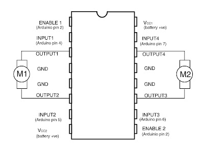
The L239D IC is a motor driver which is used to control two DC motors at a wide range of supply voltages (4.5 volts to 36 volts). Don’t connect the motors directly to Microcontroller the sharp spikes from the motor may damage the Arduino. The L239D IC has 16 legs. The connections of L239D with Arduino and DC Motors are shown in the following picture.

Programming the Arduino:
The Arduino source code for the Obstacle avoiding robot is presented below -
int enable=2;//Enable pins of L239D are connected to Arduino digital pin2int motA1=4;//pin-2 of L239D is connected to Arduino digital pin4int motA2=5;//pin-7 of L239D is connected to Arduino digital pin5int motB1=6;//pin-10 of L239D is connected to Arduino digital pin6int motB2=7;//pin-15 of L239D is connected to Arduino digital pin7int senA1=8;//sensorA first IR LED wire is connected to Arduino digital pin8int senA2=9;//sensorA second IR LED wire is connected to Arduino digital pin9int senA3=10;//sensorA Photodiode wire is connected to Arduino digital pin10int senB1=11;//sensorB first IR LED wire is connected to Arduino digital pin11int senB2=12;//sensorB second IR LED wire is connected to Arduino digital pin12int senB3=13;//sensorB Photodiode wire is connected to Arduino digital pin13int senAread=0;//wire connected between photodiode and 3 K resistor of sensorA is connectedto Arduino analog pinA0 int senBread=1;//wire connected between photodiode and 3 K resistor of sensorB is connectedto Arduino analog pinA1 void setup() { pinMode(enable,OUTPUT); digitalWrite(enable,HIGH); pinMode(motA1,OUTPUT); pinMode(motA2,OUTPUT); pinMode(motB1,OUTPUT); pinMode(motB2,OUTPUT); pinMode(senA1,OUTPUT); digitalWrite(senA1,HIGH); pinMode(senA2,OUTPUT); digitalWrite(senA2,HIGH); pinMode(senA3,OUTPUT); digitalWrite(senA3,HIGH); pinMode(senB1,OUTPUT); digitalWrite(senB1,HIGH); pinMode(senB2,OUTPUT); digitalWrite(senB2,HIGH); pinMode(senB3,OUTPUT); digitalWrite(senB3,HIGH); digitalWrite(motA1,HIGH);//digitalWrite(motA2,LOW);//In default mode both the motors will rotate forwarddigitalWrite(motB1,HIGH);//digitalWrite(motB2,LOW);//} void loop() { int val1=analogRead(senAread);// val1 variable stores the readings from sensorAint val2=analogRead(senBread);// val2 variable stores the readings from sensorBint diff=val1-val2;//calculating the difference of val1 and val2if(val1<800 || val2<800)//if any obstacle is detected by any one of the sensor{ if(diff>=0)//if obstacle is present at right side of the robot{ digitalWrite(motA2,HIGH);//digitalWrite(motA1,LOW);//make the bot move backwardsdigitalWrite(motB2,HIGH);//digitalWrite(motB1,LOW);//delay(1000);//wait for 1 seconddigitalWrite(motB2,LOW);//digitalWrite(motB1,HIGH);//turn leftdelay(700);//wait for 700 milli secondsdigitalWrite(motA1,HIGH);//digitalWrite(motA2,LOW);//move forward} else if(diff<0)//if obstacle is present at left side of the robot{ digitalWrite(motA2,HIGH);//digitalWrite(motA1,LOW);//make the bot move backwardsdigitalWrite(motB2,HIGH);//digitalWrite(motB1,LOW);//delay(1000);//wait for one seconddigitalWrite(motA2,LOW);//digitalWrite(motA1,HIGH);//turn rightdelay(700);//wait for 700 milli secondsdigitalWrite(motB1,HIGH);//digitalWrite(motB2,LOW);//move forward} } else//if no obstacle is present{ digitalWrite(motA1,HIGH);//digitalWrite(motA2,LOW);//digitalWrite(motB1,HIGH);// move forwarddigitalWrite(motB2,LOW);//} }
How program works:
The program starts with the initialization of variables. In the “void setup()” method the pin mode is set to output and the pins of sensors are made HIGH i.e., the sensors are at ON condition. Then the motors are made to move forward as a default state. In the “void loop()” method the values from the sensors are stored in variables ‘val1’ and ‘val2’ after that their difference is calculated and stored in the variable ‘diff’ which tells us whether the obstacle is present at the right side or left side (if diff is > 0 the obstacle is present at right side and if diff is < 0 the obstacle is present at the left side of the bot). An if-else ladder is used to make the robot turn according to the obstacle position. If an obstacle is present at the left side of the robot then the bot moves backwards a bit after that turn right side and the moves forwards. If the obstacle is present at right side of the bot then the bot moves backwards a bit after that turns left and then moves forward.Assembling:
Choose any available material for the chassis. I had used an aluminum frame from an old DVD-ROM for the chassis of the robot. Connect the sensors one at the right-front corner and the other at the left-front corner of the chassis (you can add another sensor at the middle of these two to increase the performance of the robot) by using a double sided tape.
Attach the castor ball in the middle at the front side of the robot with a double sided tape or any adhesive. Attach the two DC motors in the back left and right positions by using double sided tape or any adhesive. Then the bot will looks like in the below picture.

Connect the sensors according to the circuit diagram shown above after that, connect the wires of L239D motor driver according to the pin diagram of L239D IC which is shown above (be careful with the directions of motor otherwise the bot will misbehave). After that Upload the Arduino code into the Arduino Microcontroller. That’s it your bot is ready for the first use.
Is this post useful? Please feel free to comment.
Is this post useful? Please feel free to comment.
Related posts:
Basic Sensors Used in Robotics
In my previous post Getting Started with Robotics we have seen a brief introduction about basic sensors used in the field of Robotics. In this post I am going to write How to use these sensors i.e., application of these sensors in the field of Robotics with circuit diagram and programming code of Arduino Microcontroller.In this post I will show you how to use and program Temperature sensor and Photoresistor
 The name itself indicates that this sensor is used to sense the temperature. This sensor has three legs like a Transistor, first leg is Vin second one is Vout and the third one is Ground. we have to supply the voltage to Vin and Ground and take the output voltage at Vout which tells us the temperature in terms of voltage.


Before entering into the project's, let us have a look at the Arduino UNO board. The Arduino UNO Microcontroller is based on ATmega328. It has 14 digital input/output pins numbered from 0 to 13. In these 14 pins we have 6 PWM pins (Pulse Width Modulation outputs). Arduino uno has 6 analog input pins numbered from A0 to A5. The analog pins maps the input voltage between 0 and 5 Volts into integer values between 0 and 1023. You can learn more about Arduino in the official Arduino website http://www.arduino.cc.
Temperature Sensor:
The name itself indicates that this sensor is used to sense the temperature. This sensor has three legs like a Transistor, first leg is Vin second one is Vout and the third one is Ground. we have to supply the voltage to Vin and Ground and take the output voltage at Vout which tells us the temperature in terms of voltage.Temperature Sensor Project:
In this project we are going to take the temperature readings from our Temperature Sensor LM35 for every second and we are going to use the Serial monitor of Arduino IDE to display the temperature readings taken from the Temperature sensor.
Materials Required:
1) Arduino 2) Temperature Sensor LM35 3) Solid core wires.
Circuit:
The 5 V pin of Arduino UNO goes to the Vin leg of Temperature sensor (LM35), the second leg of Temperature sensor (GND) goes to one of the three Ground pins of Arduino UNO and the third leg of Temperature sensor (Vout) goes to the Analog input pin A0 of Arduino UNO. The circuit is as shown below.

Program:
int temp;//declaring temp variable to read values from temperature sensorint senPin = 0;//initialising the sensor to 0void setup() { Serial.begin(9600);//initialising serial port with a default baund rate of 9600} void loop() { temp = analogRead(senPin);//read the value from the sensorfloat degC = (5.0 * temp * 100.0)/1024.0;//convert the analog data to temperatureSerial.print((byte)degC);//prints the temperature in Serial monitordelay(1000);//wait one second}
How Program works:
The code starts with the initialisation of variable like 'temp' which is used to read the integer value from the Analog pin and the 'senPin' variable is set to 0 which indicates the temperature sensor connected to Analog pin 0. In the 'void setup()' method Serial port is initialised with a default baund rate of 9600. The 'void loop()' method is used to execute the body inside this method continuously. In the 'void loop()' method the variable 'temp' reads the data from the Analog pin 0, the next step is conversion of analog data to temperature. The 'Serial.print((byte)degC)' method writes the temperature (which is measured in previous step) in the Serial monitor after type casting. The 'delay(1000)' method holds the execution process for 1000 milli seconds (or) 1 second
If you have any trouble related to the code of any thing please feel free to comment.
Photoresistor:
Photo resistor is also called as Light Dependent Resistor (LDR). It is made up of high resistance semi-conductor. It is a sensor whose resistance changes according to the strength of light that falls on its surface. The resistance offered by this sensor decreases with the increase in the amount of light falls on its surface and vice-verse. This sensor is used to track the light or to know the strength of the light.
Photoresistor Project:
In this project we are going to measure the intensity of light in terms of 5 grades i.e.,grade 0= No light, 1=Darker, 2=Dark, 3=Normal, 4=Bright, 5=Brighter. We are going to use a series of 5 LED’s to display the grades i.e., for grade 1 one LED will be in ON state, for grade 2 two LED’s will be in ON state and so on.
Materials Required:
1)Arduino Microcontroller 2) Photoresistor 3) Resistors 4.5 k, 100 k ohms
4) 5 LED's 5) Solid core wires.
Circuit:
Connect the 4.5 k ohms Resistor in series with the Photoresistor across Vin and Ground pins of Arduino Microcontroller. Take the input value in between the 4.5 k ohm resistor and Photoresistor to Analog pin A0 of Arduino.


How it the circuit works:
The circuit works as a voltage divider. A voltage divider is a circuit consisting of two resistances across a voltage supply. An output between the two resistances will give a lower voltage depending on the values of the two resistors. The output is taken between the two resistors. The output voltage can be calculated using the formula Vout = [R2/(R1+R2)]*Vin. Where, R1 is 4.5 k ohms and R2 is the resistance offered by the Photoresistor whose value is depends on the Intensity of the light falls on it. If the Intensity of light on the Photoresistor is more, then the resistance offered by the Photoresistor will be less and vice-versa. If the resistance of the Photoresistor is more, then Vout (which is taken in between the 4.5 k ohm resistor and Photo resistor) will be more and vice-versa.
Program:
int ledPin[5] ={1,4,7,10,13};//initialising 5 LED's with pinsint pr=0;//initialising Photoresistor to pin 0void setup() { for(int i=0;i<5;i++)//setting pin mode to 5 LED's{ pinMode(ledPin[i], OUTPUT); } } void loop() { int pr_input=0;//initial value of Photoresistor is set to 0pr_input = analogRead(pr);//reading value from analog inut pin A0for(int j=0;j<5;j++)//setting all LED's to OFF state{ digitalWrite(ledPin[j],LOW); delay(2000);//wait for 2 seconds} if(pr_input<=32) { for(int j=0;j<5;j++)//Setting 5 LED's to ON state{ digitalWrite(ledPin[j],HIGH); delay(2000);//wait for 2 seconds } } else if(pr_input>32 && pr_input<=76) { for(int j=0;j<4;j++)//Setting 4 LED's to ON state{ digitalWrite(ledPin[j],HIGH); delay(2000);//wait for 2 seconds} } else if(pr_input>76 && pr_input<=184) { for(int j=0;j<3;j++)//Setting 3 LED's to ON state{ digitalWrite(ledPin[j],HIGH); delay(2000);//wait for 2 seconds} } else if(pr_input>184 && pr_input<=235) { for(int j=0;j<2;j++)//Setting 2 LED's to ON state{ digitalWrite(ledPin[j],HIGH); delay(2000);//wait for 2 seconds} } else if(pr_input>235 && pr_input<=655) { digitalWrite(ledPin[1],HIGH);//Setting 1 LED to ON statedelay(2000);//wait for 2 seconds} }
How program works:
The code starts form initialising the variables i.e., the 5 LED's and the Photoresistor. I have used an array of five variables 'ledPin[5]' which indicates 5 LED's which are connected to the output pins 1, 4, 7, 10 and 13 of Arduino. The Photoresistor variable 'pr' is set to 0. After that I had set the pin mode for the five LED's using a 'for' loop inside the 'void setup()' method. Then, to read the intensity of light from an Photoresistor and to output the result using 5 LED's continuously, I had used 'void loop()' method which executes continuously. Inside the 'void loop()' method I have initialized a new variable 'pr_input' with the value 0 and it can be used to take the input from the analog pin 0. After that I had set all the five LED's in the OFF state (initial condition). An if-else ladder is used to divide the intensity of light measured by photoresistor into 5 grades (grade 1, grade 2 ... grade 5).
How I got the values used in if-else ladder? The answer is, I had calculated the Resistance of Photoresistor, Vout from the voltage divider circuit with the use of an Multimeter, then the Analog input value related to the output voltage from the voltage divider circuit is calculated in the following cases
case 1: When Photoresistor is in a Dark room R2 = 8 K ohms => Vout = 3.2 V => Analog input value=655
case 2: When Photoresistor is normal room R2=1K ohms => Vout=0.9V => Analog input value=184
case 3: When Photoresistor is under a bright light R2=150 ohms => Vout=0.16V => Analog input value=33
By using the values between the above three cases the grades are divided ino -
Grade 0 i.e., non of the LED's are in ON state if Analog input value is grater than 655.
Grade 1 i.e., one LED is in ON state if Analog input value is in the range of 235 to 654.
Grade 2 i.e., two LED's are in ON state if Analog input value is in the range of 184 to 234.
Grade 3 i.e., three LED's are in ON state if Analog input value is in the range of 76 to 183.
Grade 4 i.e., four LED's are in ON state if Analog input value is in the range of 32 to 75.
Grade 5 i.e., five LED's are in ON state if Analog input value is less than 31.
This process i.e., reading the intensity of light using Photo resistor and display the output using 5 LED's continues for every 2 seconds.
GETTING STARTED WITH ROBOTICS
 In this post I am going to tell you how to get into the field of Robotics, what one should learn before going to build your first robot of robotics and When we hear the word ‘Robot’ we generally assumes a human like structure made up of metal some thing like in the picture. but it is one of the types of robots called Humanoid Robot.
A Robot is a goal oriented Electromechanical device that can sense, plan and act.
What one should need to learn before building the first Robot?
Recommended pdf files to learn how to use 'Arduino' are below -
The name itself indicates that this sensor is used to sense the
temperature. This sensor has three legs like a Transistor, one leg is Vin second
one is Vout and the third one is Ground. we have to supply the voltage to Vin
and Ground and take the output voltage at Vout which tells us the temperature in
terms of voltage.
 The Ultrasonic Distance Measuring sensor (Transducer) works
on the principle similar to Radar but, this sensor uses ultrasonic (high
frequency) sound waves instead of radio waves. This sensor has two
cylindrical shaped objects one sends the ultrasonic waves and the other
receives the echo generated after striking an obstacle. The delay
between the source signal and echo signal will determines the distance
at which the object is presented higher is the delay higher is the
distance of the obstacle and vice-verse.
 PIR sensor means Passive Infrared sensor. It is used to
detect any motion/moment. It is widely used for security purpose and
robotics. It works from a voltage range of 3.3 V to 5 V and
produces the output in terms of voltage which can be directly
connected to Micro controller or to a Relay through a Transistor. It
is generally used to detect any motion in front of it .Most PIR sensors
have a range of 120 degrees.
and many more......................
 In this post I am going to tell you how to get into the field of Robotics, what one should learn before going to build your first robot of robotics and When we hear the word ‘Robot’ we generally assumes a human like structure made up of metal some thing like in the picture. but it is one of the types of robots called Humanoid Robot.
So what is a robot?
There are many definitions that describes the term 'Robot' let us see one of them -
A Robot is a goal oriented Electromechanical device that can sense, plan and act.
What one should need to learn before building the first Robot?
As we know that Robot is a Electromechanical Device which implements the program(Software) so, before building your first Robot it is better to know the basics in these three fields (Mechanics, Electronics and Software).
In the field of Mechanics we have to concentrate on the topics like Dynamics, Kinetics and Inverse Kinetics etc.,
In the field of Electronics we have to know about some basic Electrical components like Resistor's, Diode's, Transistor's, FET's, UJT's, Capacitor's, Inductor's etc., and their application and calculations in the circuitry.
In the field of Software(programming) it is advisable to learn at least basics of 'C' Language to start programming the robot because, popular Micro controllers like Arduino, PIC etc., are programmed in the language which is similar to 'C' Language.
It is always advisable to gather the basic knowledge before entering into any field so, before building the first robot it is better to have some basic knowledge about different types of components used to built a robot. Some basic components/things required to built a robot are - Micro controller, Sensors, Motors, wheels, Software etc.,
A detailed description about basic components used to built a robot is as follows-
1. Micro controller:
We all know that C.P.U(Central Processing Unit ) is the brain of the computer similarly the Micro controller is the brain of the Robot. A Micro controller is a small computer on a small Integrated circuit. The Micro controller allows the user to interact with the Sensors, Motors and other parts of the Robot. Whatever the program prepared for the robot will executed by the Micro controller. With out the Micro controller the Robot is nothing but a Electromechanical toy. Micro controllers are not only used in Robots they also used in Cars, CD/DVD players, Automobile Engines, Remote controlled Devices etc.,.
Some famous micro controllers used in the field of Robotics are: Arduino, PIC, IntelliBrain etc.,
and software. The Micro controller on the board is programmed using Arduino programming language
(Similar to 'C' language) using the Arduino Integrated Development Environment (IDE). The Arduino
can compatible with other softwares like Flash, Processing, MaxMSP. MatLab provides a special tool
to interact with Arduino.
The following is the picture of Arduino uno Micro controller.

Arduino:
Arduino is an open-source Electronics prototyping platform based on easy to use hardwareand software. The Micro controller on the board is programmed using Arduino programming language
(Similar to 'C' language) using the Arduino Integrated Development Environment (IDE). The Arduino
can compatible with other softwares like Flash, Processing, MaxMSP. MatLab provides a special tool
to interact with Arduino.
The following is the picture of Arduino uno Micro controller.

I think for the beginners Arduino Micro controller is the best(If you are familiar with C
programming). The reasons are -
programming). The reasons are -
1) It has a large community over the Internet to help us
2) It is a Open source device.
3) Easy to program using the Arduino IDE.
4) It is easily available at any embedded store.
5) Relatively less price.
Recommended pdf files to learn how to use 'Arduino' are below -
1) Getting started with Arduino by O'Reilly
2) Getting Started with Arduino
2.PIC Micro controller:
PIC Micro controllers are popular among Industrial Developers and hobbyists due to
their low cost, wide availability, large user base, extensive collection of application notes, availability of
low cost or free development tools, and serial programming (and re-programming with flash memory)
capability. They are also commonly used in educational programming as they often come with the easy
to use 'pic logicator' software
2. Sensors:
Human beings sense the world with our sense organs like eyes, nose, ears, tongue and skin. but, what about Robot?
Robot need sensors to sense the world around it. Some of widely used sensors in the field of Robotics are IR LED's, Photo Resistors, IR range finders, Ultrasonic range finders, Temperature sensors, PIR Motion detection sensors, VGA sensor(VGA Camera) etc., The following is the detailed description of above mentioned Sensors
 IR LED means Infrared Light Emitting Diode. The IR LED emits
Infrared light which is not visible to human eye. we can find these IR LED's in
our TV Remotes. IR LED's works like normal LED's but the material used in
the core is different, it emits Infrared Light when current passed through it (in
case of IR LED). These IR LED are used to detect obstacles ahead of the
robot. The IR LED emits IR light which gets reflected if any obstacle is present
in the direction on emitted IR ray, the reflected IR ray caught by Photo diode which
calculates the reflected light strength. The higher the reflected IR ray strength the
closer is the obstacle and vice-verse
 Photo resistor is also called as Light Dependent Resistor
(LDR). It is made up of high resistance semi-conductor. It is a
sensor whose resistance changes according to the strength of light
that falls on its surface. The resistance offered by this sensor
decreases with the increase in the amount of light falls on its
surface and vice-verse. This sensor is used to track the light or to
know the strength of the light.
IR LED :
IR LED means Infrared Light Emitting Diode. The IR LED emits Infrared light which is not visible to human eye. we can find these IR LED's in
our TV Remotes. IR LED's works like normal LED's but the material used in
the core is different, it emits Infrared Light when current passed through it (in
case of IR LED). These IR LED are used to detect obstacles ahead of the
robot. The IR LED emits IR light which gets reflected if any obstacle is present
in the direction on emitted IR ray, the reflected IR ray caught by Photo diode which
calculates the reflected light strength. The higher the reflected IR ray strength the
closer is the obstacle and vice-verse
2.Photoresistor:
 Photo resistor is also called as Light Dependent Resistor
 (LDR). It is made up of high resistance semi-conductor. It is a
sensor whose resistance changes according to the strength of light
that falls on its surface. The resistance offered by this sensor
decreases with the increase in the amount of light falls on its
surface and vice-verse. This sensor is used to track the light or to
know the strength of the light.
3.Temperature Sensor:
The name itself indicates that this sensor is used to sense the temperature. This sensor has three legs like a Transistor, one leg is Vin second
one is Vout and the third one is Ground. we have to supply the voltage to Vin
and Ground and take the output voltage at Vout which tells us the temperature in
terms of voltage.
4.Ultrasonic Transducer:
The Ultrasonic Distance Measuring sensor (Transducer) workson the principle similar to Radar but, this sensor uses ultrasonic (high
frequency) sound waves instead of radio waves. This sensor has two
cylindrical shaped objects one sends the ultrasonic waves and the other
receives the echo generated after striking an obstacle. The delay
between the source signal and echo signal will determines the distance
at which the object is presented higher is the delay higher is the
distance of the obstacle and vice-verse.
5.IR Range Finder:
IR Range Finder (IR Distance Measuring Sensor) is a sensor
used to find the distance of an object from where it is placed. The IR
Range Finder has an IR Source (IR LED) and IR Receiver
 (Photo diode). The IR Source sends the IR rays and the IR receiver
(Photo diode). The IR Source sends the IR rays and the IR receiver
receives the IR rays which get reflected by any obstacle. The
difference between IR Rang Finder and Ultrasonic Transducer is IR
Range Finder uses IR rays but Ultrasonic Transducer uses high
frequency sound waves. IR Range Finder is more accurate in indoor
but it may give false readings at outdoor because the IR rays from sun
may be detected along with the reflected IR rays from an obstacle
but it may give false readings at outdoor because the IR rays from sun
may be detected along with the reflected IR rays from an obstacle
6)PIR Motion Detection Sensor:
PIR sensor means Passive Infrared sensor. It is used todetect any motion/moment. It is widely used for security purpose and
robotics. It works from a voltage range of 3.3 V to 5 V and
produces the output in terms of voltage which can be directly
connected to Micro controller or to a Relay through a Transistor. It
is generally used to detect any motion in front of it .Most PIR sensors
have a range of 120 degrees.
and many more......................
3.Motors:
A motors is a Electromechanical device that converts Electrical energy into rotational Torque. The hierarchy of the motors are divided into two types A.C (Alternate Current) motors and D.C (Direct Current) motors. In general we use D.C motors in the field of robotics.so let us ignore the A.C motors for now and concentrate on D.C motors.
The D.C motors are divided into several types based on several factors. The different types of D.C motors are - Brushed D.C motor, Brush less D.C motor, Servo motor, Stepper motors etc.,
let us see detailed description about different types of D.C motors used in the field of robotics -
 1.Brushed D.C Motors:

Brushed D.C Motor is a class of D.C motor which
has a permanent magnet stator and a wounded Iron-core
armature. The speed of the Brushed D.C motor can be
varied by varying the supply voltage. The direction of
rotation of these motors is depends on the polarity of the
supply voltage. Brushed D.C motors are widely used
because these motors are easily available in market and not
expensive.
 Brush less D.C Motors (BLDC motors) also known
 Servo Motor is a rotatory actuator with a precise control
 A Stepper Motor is a Brush less D.C electric motor
has a permanent magnet stator and a wounded Iron-core
armature. The speed of the Brushed D.C motor can be
varied by varying the supply voltage. The direction of
rotation of these motors is depends on the polarity of the
supply voltage. Brushed D.C motors are widely used
because these motors are easily available in market and not
expensive.
2.Brush less D.C Motors:
 Brush less D.C Motors (BLDC motors) also known
as Electrically commutated motors. These motors are
powered by D.C source through an integrated inventor
which generates A.C signals (not sinusoidal but bi-
directional) to drive the motor. We can't drive a Brush less
D.C Motor directly with a battery. To operate the BLDC
motor we need special circuitry. BLDC motors has 3 wires.
The BLDC motors are designed to over come the disadvantages
of Brushed D.C motors. The BLDC motors have Higher efficiency,
less susceptibility and low mechanical wear and tear. You can find
these BLDC motors inside the DVD Drive of our Computer.
The BLDC motors are designed to over come the disadvantages
of Brushed D.C motors. The BLDC motors have Higher efficiency,
less susceptibility and low mechanical wear and tear. You can find
these BLDC motors inside the DVD Drive of our Computer.
3.Servo Motors:
 Servo Motor is a rotatory actuator with a precise control
of angular position i.e., with the help of this motors we can
control the rotor of the motor to the desired position (angle).
Unlike normal motors Servo Motors cannot rotate continuously.
Most of the Servo motors have a rotational range of 180
degrees some Servos has a range of 120 degrees some Servos
can has a range of 90 degrees. To operate these Servos to a
particular position we need Pulse Width Modulation (PWM)
signal. The Servo Motor use the feedback from a Potentiometer
(POT) inside the servo to turn its rotor to the desired motor.
There is a built in circuitry in the motor so, we do not need to
construct extra circuitry. The servo motors has three wires one is
Vin the second is Ground the third wire is for the control signal
which determines the position of the rotor. There are a wide range of
Servos available depending up on Torque, size etc.,
4.Stepper Motors:
 A Stepper Motor is a Brush less D.C electric motor
that divides the full rotation into number of equal steps. The
motors position can be commanded to move and hold at one
of these steps with out any feedback sensor.These Stepper
Motors are useful when we need precise control of angular
position with out any restriction of limited rotation like Servos.
These motors are expensive. Most of the Stepper motors
have 200 steps per rotation. we need a Stepper Motor Driver
circuit to drive this motor
4. Motor Shield:
A Motor Shield is nothing but circuitry to drive the Motors. Direct connection of Motors to the Micro controller is not advisable.
The reasons are –
The reasons are –
1) The induction coils in the motor may produce high voltage spikes which may damage the Micro controller
2) Micro Controllers Output pin produces 5 V and nearly 50 Milli amps of current which is not sufficient to run large motors.

5. Wheels and Tracks:
A wheel is a circular component that is intended to rotate on a axial. To make a mobile(free to move) robot we needs wheels. For un-even surfaces Track belts may be useful. we can find these Track belt system in military tanks.
The following are the pictures of Wheels and Track.


The following are the pictures of Wheels and Track.


RPLIDAR 360° Laser Scanner - RobotShop
The Case against Killer Robos
ith the rapid development and proliferation of robotic weapons, machines are starting to take the place of humans on the battlefield. Some military and robotics experts have predicted that “killer robots”—fully autonomous weapons that could select and engage targets without human intervention—could be developed within 20 to 30 years. At present, military officials generally say that humans will retain some level of supervision over decisions to use lethal force, but their statements often leave open the possibility that robots could one day have the ability to make such choices on their own power. Human Rights Watch and Harvard Law School’s International Human Rights Clinic (IHRC) believe that such revolutionary weapons would not be consistent with international humanitarian law and would increase the risk of death or injury to civilians during armed conflict. A preemptive prohibition on their development and use is needed.A relatively small community of specialists has hotly debated the benefits and dangers of fully autonomous weapons. Military personnel, scientists, ethicists, philosophers, and lawyers have contributed to the discussion. They have evaluated autonomous weapons from a range of perspectives, including military utility, cost, politics, and the ethics of delegating life-and-death decisions to a machine. According to Philip Alston, then UN special rapporteur on extrajudicial, summary or arbitrary executions, however, “the rapid growth of these technologies, especially those with lethal capacities and those with decreased levels of human control, raise serious concerns that have been almost entirely unexamined by human rights or humanitarian actors.”[1] It is time for the broader public to consider the potential advantages and threats of fully autonomous weapons.
The primary concern of Human Rights Watch and IHRC is the impact fully autonomous weapons would have on the protection of civilians during times of war. This report analyzes whether the technology would comply with international humanitarian law and preserve other checks on the killing of civilians. It finds that fully autonomous weapons would not only be unable to meet legal standards but would also undermine essential non-legal safeguards for civilians. Our research and analysis strongly conclude that fully autonomous weapons should be banned and that governments should urgently pursue that end.
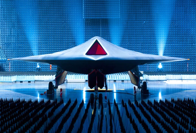
Fully autonomous weapons, which are the focus of this report, do not yet exist, but technology is moving in the direction of their development and precursors are already in use. Many countries employ weapons defense systems that are programmed to respond automatically to threats from incoming munitions. Other precursors to fully autonomous weapons, either deployed or in development, have antipersonnel functions and are in some cases designed to be mobile and offensive weapons. Militaries value these weapons because they require less manpower, reduce the risks to their own soldiers, and can expedite response time. The examples described in this report show that a number of countries, most notably the United States, are coming close to producing the technology to make complete autonomy for robots a reality and have a strong interest in achieving this goal.
As this report shows, robots with complete autonomy would be incapable of meeting international humanitarian law standards. The rules of distinction, proportionality, and military necessity are especially important tools for protecting civilians from the effects of war, and fully autonomous weapons would not be able to abide by those rules. Roboticists have proposed different mechanisms to promote autonomous weapons’ compliance with these rules; options include developing an ability to process quantitative algorithms to analyze combat situations and “strong artificial intelligence (AI),” which would try to mimic human thought. But even with such compliance mechanisms, fully autonomous weapons would lack the human qualities necessary to meet the rules of international humanitarian law. These rules can be complex and entail subjective decision making, and their observance often requires human judgment. For example, distinguishing between a fearful civilian and a threatening enemy combatant requires a soldier to understand the intentions behind a human’s actions, something a robot could not do. In addition, fully autonomous weapons would likely contravene the Martens Clause, which prohibits weapons that run counter to the “dictates of public conscience.”
By eliminating human involvement in the decision to use lethal force in armed conflict, fully autonomous weapons would undermine other, non-legal protections for civilians. First, robots would not be restrained by human emotions and the capacity for compassion, which can provide an important check on the killing of civilians. Emotionless robots could, therefore, serve as tools of repressive dictators seeking to crack down on their own people without fear their troops would turn on them. While proponents argue robots would be less apt to harm civilians as a result of fear or anger, emotions do not always lead to irrational killing. In fact, a person who identifies and empathizes with another human being, something a robot cannot do, will be more reluctant to harm that individual. Second, although relying on machines to fight war would reduce military casualties—a laudable goal—it would also make it easier for political leaders to resort to force since their own troops would not face death or injury. The likelihood of armed conflict could thus increase, while the burden of war would shift from combatants to civilians caught in the crossfire.
Finally, the use of fully autonomous weapons raises serious questions of accountability, which would erode another established tool for civilian protection. Given that such a robot could identify a target and launch an attack on its own power, it is unclear who should be held responsible for any unlawful actions it commits. Options include the military commander that deployed it, the programmer, the manufacturer, and the robot itself, but all are unsatisfactory. It would be difficult and arguably unfair to hold the first three actors liable, and the actor that actually committed the crime—the robot—would not be punishable. As a result, these options for accountability would fail to deter violations of international humanitarian law and to provide victims meaningful retributive justice.
The primary concern of Human Rights Watch and IHRC is the impact fully autonomous weapons would have on the protection of civilians during times of war. This report analyzes whether the technology would comply with international humanitarian law and preserve other checks on the killing of civilians. It finds that fully autonomous weapons would not only be unable to meet legal standards but would also undermine essential non-legal safeguards for civilians. Our research and analysis strongly conclude that fully autonomous weapons should be banned and that governments should urgently pursue that end.
Definitions and Technology
Although experts debate the precise definition, robots are essentially machines that have the power to sense and act based on how they are programmed.[2] They all possess some degree of autonomy, which means the ability of a machine to operate without human supervision. The exact level of autonomy can vary greatly. Robotic weapons, which are unmanned, are often divided into three categories based on the amount of human involvement in their actions:- Human-in-the-Loop Weapons: Robots that can select targets and deliver force only with a human command;
- Human-on-the-Loop Weapons: Robots that can select targets and deliver force under the oversight of a human operator who can override the robots’ actions; and
- Human-out-of-the-Loop Weapons: Robots that are capable of selecting targets and delivering force without any human input or interaction.
Fully autonomous weapons, which are the focus of this report, do not yet exist, but technology is moving in the direction of their development and precursors are already in use. Many countries employ weapons defense systems that are programmed to respond automatically to threats from incoming munitions. Other precursors to fully autonomous weapons, either deployed or in development, have antipersonnel functions and are in some cases designed to be mobile and offensive weapons. Militaries value these weapons because they require less manpower, reduce the risks to their own soldiers, and can expedite response time. The examples described in this report show that a number of countries, most notably the United States, are coming close to producing the technology to make complete autonomy for robots a reality and have a strong interest in achieving this goal.
Safeguards for Civilian Protection
According to international law and best practices, states should evaluate new or modified weapons to ensure they do not violate the provisions of international humanitarian law, also called the laws of war.[5] States should conduct weapons reviews at the earliest stages of development and continue them up through any production decision. Given military plans to move toward increasing autonomy for robots, states should now undertake formal assessments of the impacts of proposed fully autonomous weapons and technology that could lead to them even if not yet weaponized.As this report shows, robots with complete autonomy would be incapable of meeting international humanitarian law standards. The rules of distinction, proportionality, and military necessity are especially important tools for protecting civilians from the effects of war, and fully autonomous weapons would not be able to abide by those rules. Roboticists have proposed different mechanisms to promote autonomous weapons’ compliance with these rules; options include developing an ability to process quantitative algorithms to analyze combat situations and “strong artificial intelligence (AI),” which would try to mimic human thought. But even with such compliance mechanisms, fully autonomous weapons would lack the human qualities necessary to meet the rules of international humanitarian law. These rules can be complex and entail subjective decision making, and their observance often requires human judgment. For example, distinguishing between a fearful civilian and a threatening enemy combatant requires a soldier to understand the intentions behind a human’s actions, something a robot could not do. In addition, fully autonomous weapons would likely contravene the Martens Clause, which prohibits weapons that run counter to the “dictates of public conscience.”
By eliminating human involvement in the decision to use lethal force in armed conflict, fully autonomous weapons would undermine other, non-legal protections for civilians. First, robots would not be restrained by human emotions and the capacity for compassion, which can provide an important check on the killing of civilians. Emotionless robots could, therefore, serve as tools of repressive dictators seeking to crack down on their own people without fear their troops would turn on them. While proponents argue robots would be less apt to harm civilians as a result of fear or anger, emotions do not always lead to irrational killing. In fact, a person who identifies and empathizes with another human being, something a robot cannot do, will be more reluctant to harm that individual. Second, although relying on machines to fight war would reduce military casualties—a laudable goal—it would also make it easier for political leaders to resort to force since their own troops would not face death or injury. The likelihood of armed conflict could thus increase, while the burden of war would shift from combatants to civilians caught in the crossfire.
Finally, the use of fully autonomous weapons raises serious questions of accountability, which would erode another established tool for civilian protection. Given that such a robot could identify a target and launch an attack on its own power, it is unclear who should be held responsible for any unlawful actions it commits. Options include the military commander that deployed it, the programmer, the manufacturer, and the robot itself, but all are unsatisfactory. It would be difficult and arguably unfair to hold the first three actors liable, and the actor that actually committed the crime—the robot—would not be punishable. As a result, these options for accountability would fail to deter violations of international humanitarian law and to provide victims meaningful retributive justice.
What is Gesture Recognition Technology? – A Glimpse of the Future
 Ever since the dawn of time, man has worked tirelessly to make life better. With the advent of computers and the internet, communication and information transfer has become extremely easy. But there’s always been one common way of interacting with these machines.
No matter how powerful and complex, you always have to be near a machine and somehow in physical contact with it to interact with it. But gesture recognition technology could change all that. If perfected and used correctly, it could actually render traditional input devices like keyboard, mice and touch screens redundant. Read on to find out more! In simple words, gesture recognition is the science of interpreting human gestures as input commands using mathematical algorithms. This may include full body motion recognition, or something small like a change in facial expression. Although it might seem small, however, reading facial expressions is in fact a more difficult task than recognizing more pronounced gestures.
Generally, gestures are classified into two types. Depending on the level of interaction required, different types are used, and it’s not always necessary to use one over the other, it does make things simpler to understand though. The two types of gestures are:
- Online Gestures – Put simply, these are gestures that control a machine or computer system in real time. Also called direct manipulation gestures, these are the sort that let you interact with objects and impose changes viewable as you do them.
- Offline Gestures – Gestures that are processed after they’re done are called offline gestures. In other words, these are the gestures that don’t show a real time change. For example, some new smartphones have the option to open a certain application after a specific gesture is made, this is basically an offline gesture.
- Medical Applications – Advanced robotics systems with gesture recognition can be placed in hospitals or homes to recognize and treat life threatening conditions like heart attacks or strokes.
- Alternative computer interfaces – Gesture recognition, along with voice recognition, facial recognition, lip movement recognition and eye tracking combined can be used to create something called a perceptual user interface (PUI), a completely different way to interact with computer systems which will improve usability and creativity by leaps and bounds.
- Entertainment applications – Most videogames today are played either on game consoles, arcade units or PCs, and all require a combination of input devices. Gesture recognition can be used to truly immerse a players in the game world like never before.
- Automation systems – In homes, offices, transport vehicles and more, gesture recognition can be incorporated to greatly increase usability and reduce the resources necessary to create primary or secondary input systems like remote controls, car entertainment systems with buttons or similar.
- An easier life for the disabled – One of the biggest challenges faced today is providing separate and equally non cumbersome services to the differently abled and handicapped. While there are special provisions around the world, there’s still huge room for improvement to bring all lives on equal footing. Gesture recognition technology can eliminate a lot of manual labor and make life much easier for those who aren’t as fortunate as most of us are.
 These are just a handful of the places and situations in which gesture recognition technology can be implemented, and as is evident, can totally change the way we interact with the world around us, not only at home, but in commercial venues as well. In fact, a South African company had come up with an innovative machine placed at the Tambo International Airport that detected travellers who yawned or looked sleepy and dispensed free cups of coffee. Although it used only basic facial and gesture recognition technology, it is nonetheless an interesting look into what can be done with this technology. Currently, there aren’t too many gesture recognition applications available for public use, but interestingly, despite its potential for real world applications, gesture recognition technology is actually dominated by the videogame industry. Electronics giants Microsoft and Sony, makers of the Xbox and PlayStation line of consoles respectively, have incorporated gesture recognition to an extent into their entertainment systems, via extra hardware. Called ‘Kinect’ in the case of Microsoft and the ‘PlayStation Eye/Camera’ in the case of Sony, these amazing devices bring us one step closer to the future. While Microsoft in 2014 has gone ahead and included the Kinect 2.0 camera with the Xbox One, their latest gaming console and made gesture and voice control an integral part of it, Sony has left the PlayStation Camera as an accessory for the PlayStation 4, instead focusing on traditional input methods.
Microsoft Kinect
First introduced with as an accessory to the Xbox 360 in 2009, the Kinect was not exactly a huge hit, but paved the way for meaningful gesture controlled gaming. The initial iteration was based on camera technology from Israeli developer PrimeSense, and featured an RGB camera, depth sensor and multi array microphone to provide facial, gesture and voice recognition. The depth laser was basically an infrared laser projector and CMOS sensor that let the device capture point to point 3D data regardless of ambient light, an extremely important factor that would vary wildly from household to household, or for that matter, anywhere the console is used.
Sony PlayStation Eye/Camera
First released as the PlayStation EyeToy for the venerable PlayStation 2 console, the EyeToy was simply a glorified webcam, and didn’t really track gestures as accurately as its successors would. There were games released using this mechanism, but weren’t well received because of the low sensitivity. It basically just captured your image/video and pasted it in the game, and didn’t really track you. The PlayStation Eye was the next product in Sony’s line of gesture recognition technology for entertainment systems/game consoles. Launched in 2007, it could capture video at 640 x 480 px and was said to be ‘two times as sensitive’ as the PlayStation EyeToy. Again, it was just an evolution of its predecessors, and didn’t bring much to the table in terms of tracking. Used for simple Digimask face mapping, video chatting, edge detection and color tracking, the PlayStation Eye was a small step forward for Sony. The PlayStation Camera for the PlayStation 4 is actually similar to what Microsoft has been doing with the Kinect range of devices. Featuring two 1280 x 800 pixel cameras with an 85 degree field of view that can be used for depth tracking, motion sensing and other functions depending on applications, the PlayStation Camera is another really interesting chapter in gesture recognition technology. It works in conjunction with the PlayStation 4 controller to track motion, faces, people and voices, quite like the Kinect. Most famously used to show off the “Playroom” demo, the PlayStation Camera is an interesting device made slightly differently but for the same purpose.
Leap Motion
Now for what is perhaps the most accessible and easy to use gesture recognition platform, Leap Motion. Growing from investor interest in 2010, Leap Motion just started selling their devices in July 2013 commercially. So what exactly is Leap Motion? It’s a hardware sensor device that tracks hand and finger motions and translates it into input. The Leap Motion controller is a small USB powered device compatible with Windows and Macintosh that uses two monochromatic IR cameras and three IR LEDs to track movements and motion made by hands and fingers in a roughly 1m hemispherical 3D space. The cameras reportedly generate 300 frames per second of data, which is analysed and interpreted by proprietary software. It’s like a smaller version of the Kinect, except only incorporating gesture recognition in a smaller space. However, unlike the Microsoft Kinect and Sony PlayStation Eye/Camera, Leap Motion finds uses in a far wider range of applications since it’s connected to PCs. Leap Motion is also available as part of ASUS and Hewlett-Packard laptops and keyboards, incorporating the controller into the laptop chassis and thus eliminating the need for extra hardware. While mostly used for gaming applications currently, Leap Motion is quickly gaining popularity in design, social and creative applications, since it breaks the conventional keyboard and mouse usage to bring far greater control to the hands of developers and creators. There are already applications in which Leap Motion technology is being used to control robots, which opens up a whole new world of possibilities. Considering the fact that a Leap Motion controller costs just 100$ and there are already applications and games being developed exclusively for it, Leap Motion is perhaps the biggest step forward for gesture recognition technology. While the PlayStation Eye/Camera does a great job of advancing this, it can’t be argued that the lack of developer access and a closed ecosystem prevents it from reaching the heights it truly can. The Kinect, on the other hand, is already available for purchase, and the Kinect 2.0 will hit stores soon, with an SDK (software development kit) in tow for developers to truly play around and create something amazing. Leap Motion technology is now already finding its way to laptops and tablets, and is not even significantly expensive, so can prove to be a big player in the gesture recognition game. It’s truly exciting to see that gesture recognition technology is catching on, and manufacturers granting access to developer’s means that pretty soon we might see something totally amazing that even the creators themselves didn’t imagine. Man has always pushed the boundaries with technology, and the work of a few can actually change the world in this case. Perhaps a future where I would be typing this without even using a keyboard isn’t so far away, and perhaps a future where we don’t even need to physically be in touch with household appliances isn’t so far away. Most importantly, maybe a world where the differently abled will be able to do everything without extra help isn’t too far away either.
In keeping with the escalating use of aerial drones, government planning documents and spending figures indicate that the military of the future will be increasingly unmanned. In recent years, for example, the US Department of Defense has spent approximately $6 billion annually on the research and development, procurement, operations, and maintenance of unmanned systems for war, and that figure is likely to increase rapidly. Drones are seen as just the beginning of a technological revolution. As robotic warfare expert Peter W. Singer suggests, “Predators are merely the first generation—the equivalent of the Model T Ford or the Wright Brothers’ Flyer.”
Unmanned technology possesses at least some level of autonomy, which refers to the ability of a machine to operate without human supervision. At lower levels, autonomy can consist simply of the ability to return to base in case of a malfunction. If a weapon were fully autonomous, it would “identify targets and … trigger itself.” Today’s robotic weapons still have a human being in the decision-making loop, requiring human intervention before the weapons take any lethal action. The aerial drones currently in operation, for instance, depend on a person to make the final decision whether to fire on a target. As this chapter illustrates, however, the autonomy of weapons that have been deployed or are under development is growing quickly. If this trend continues, humans could start to fade out of the decision-making loop, retaining a limited oversight role—or perhaps no role at all.
Plans for Autonomy
Military policy documents, especially from the United States, reflect clear plans to increase the autonomy of weapons systems. In its Unmanned Systems Integrated Roadmap FY2011-2036, the US Department of Defense wrote that it “envisions unmanned systems seamlessly operating with manned systems while gradually reducing the degree of human control and decision making required for the unmanned portion of the force structure.” The US plans cover developments in ground, air, and underwater systems. A US roadmap specifically for ground systems stated, “There is an ongoing push to increase UGV [unmanned ground vehicle] autonomy, with a current goal of ‘supervised autonomy,’ but with an ultimate goal of full autonomy.” According to the US Air Force, “[i]ncreasingly humans will no longer be ‘in the loop’ but rather ‘on the loop’—monitoring the execution of certain decisions. Simultaneously, advances in AI will enable systems to make combat decisions and act within legal and policy constraints without necessarily requiring human input.” A 2004 US Navy planning document on unmanned undersea vehicles (UUVs) stated, “While admittedly futuristic in vision, one can conceive of scenarios where UUVs sense, track, identify, target, and destroy an enemy—all autonomously.” Other countries are also devoting attention and money to unmanned systems.While emphasizing the desirability of increased autonomy, many of these military documents also stress that human supervision over the use of deadly force will remain, at least in the immediate future. According to the US Department of Defense, “[f]or the foreseeable future, decisions over the use of force and the choice of which individual targets to engage with lethal force will be retained under human control in unmanned systems.” The UK Ministry of Defence stated in 2011 that it “currently has no intention to develop systems that operate without human intervention in the weapon command and control chain.” Such statements are laudable but do not preclude a change in that policy as the capacity for autonomy evolves.
Although the timeline for that evolution is debated, some military experts argue that the technology for fully autonomous weapons could be achieved within decades. The US Air Force predicted that “by 2030 machine capabilities will have increased to the point that humans will have become the weakest component in a wide array of systems and processes.” The UK Ministry of Defence estimated in 2011 that artificial intelligence “as opposed to complex and clever automated systems” could be achieved in 5 to 15 years and that fully autonomous swarms could be available in 2025. Other experts have quoted similar estimates while cautioning that intelligence for weapons that equals that of a human is much further off, and many experts believe it is impossible.
The next two sections examine the development of increasingly autonomous weapons. They are not the focus of this report, which instead highlights the risks posed by fully autonomous weapons. They show, however, that autonomous technology already exists and is evolving rapidly. An analysis of these weapons also leads to the conclusion that development of greater autonomy should proceed cautiously, if at all.
Automatic Weapons Defense Systems
Automatic weapons defense systems represent one step on the road to autonomy. These systems are designed to sense an incoming munition, such as a missile or rocket, and to respond automatically to neutralize the threat. Human involvement, when it exists at all, is limited to accepting or overriding the computer’s plan of action in a matter of seconds.
The US Navy’s MK 15 Phalanx Close-In Weapons System is designed to identify and fire at incoming missiles or threatening aircraft. This automatic weapons defense system, shown during a live fire exercise, is one step on the road to full autonomy. Photograph by Chief Fire Controlman Brian Kirkwood, US Navy.
The United States has several such systems. The US Navy’s MK 15 Phalanx Close-In Weapons System, the earliest model, was first installed on a ship in 1980, and modified versions are still widely used by the United States and its allies. It is designed to sense approaching anti-ship missiles or threatening aircraft and respond with fire from two 20mm guns with six rotating barrels. The guns each fire 3,000 to 4,500 rounds per minute More recent models aim to defend against small gunboats, artillery, and helicopters. The Navy describes the Phalanx as “the only deployed close-in weapon system capable of autonomously performing its own search, detect, evaluation, track, engage and kill assessment functions.”The Counter Rocket, Artillery, and Mortar System (C-RAM) is a US land-based version of the Phalanx. The United States first deployed it at forward operating bases in Iraq in 2005. Twenty-two systems reportedly had more than 100 successful intercepts of rockets, artillery, and mortars and provided more than 2,000 warnings to troops. Like the Phalanx, it can fire 20mm rounds from a six-barrel gun at an incoming munition. According to one US Army publication, after the C-RAM detects a threat, “a human operator certif[ies] the target,” but that would have to happen almost instantaneously in order for the C-RAM to destroy the incoming munition in time.
Other countries have developed comparable weapons defense systems. Israel has deployed its Iron Dome near the border with Gaza and in Eilat, near the Sinai Peninsula. It uses radar to identify short-range rockets and 155mm artillery shells up to 70 kilometers away. It is armed with 20 Tamir interceptor missiles to respond to such threats, and extended range versions of those missiles are reportedly scheduled to be available in early 2013.Israel has received financial support for the Iron Dome from the United States, and the US Department of Defense stated that the system, which reportedly has more than an 80 percent success rate, “has shot down scores of missiles that would have killed Israeli civilians since it was fielded in April 2011.” In a split second after detecting an incoming threat, the Iron Dome sends a recommended response to the threat to an operator. The operator must decide immediately whether or not to give the command to fire in order for the Iron Dome to be effective.
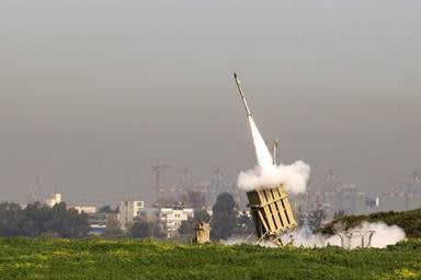
An Iron Dome, an Israeli automatic weapons defense system, fires a missile from the city of Ashdod in response to a rocket launch from the nearby Gaza Strip on March 11, 2012. The Iron Dome sends warnings of incoming threats to an operator who must decide almost instantly whether to give the command to fire. © 2012 Jack Guez, AFP/Getty Images
Another example of an automatic weapons defense system is the NBS Mantis, which Germany designed to protect its forward operating bases in Afghanistan. The “short-range force protection system will detect, track and shoot the projectiles within a close range of the target base.” Within 4.5 seconds after detecting targets about three kilometers away, it can fire six 35mm automatic guns at 1,000 rounds per minute. The system has a “very high degree of automation, including automatic target detection and engagement processes which the operator only has to monitor.” Sources were unclear whether “monitoring” also allowed the operator to override the process.These weapon defense systems have a significant degree of autonomy because they can sense and attack targets with minimal human input. Technically, they fall short of being fully autonomous and can better be classified as automatic. Robotics professor Noel Sharkey defines an automatic robot as one that “carries out a pre-programmed sequence of operations or moves in a structured environment. A good example is a robot arm painting a car.” An autonomous robot, he continues, “is similar to an automatic machine except that it operates in open and unstructured environments. The robot is still controlled by a program but now receives information from its sensors that enable it to adjust the speed and direction of its motors (and actuators) as specified by the program.”Nevertheless, while not the focus of this report, these automatic defense systems can be seen as a step toward greater autonomy in weapons.
As weapons that operate with limited intervention from humans, automatic weapons defense systems warrant further study. On the one hand, they seem to present less danger to civilians because they are stationary and defensive weapons that are designed to destroy munitions, not launch offensive attacks. On the other hand, commentators have questioned the effectiveness of the human supervision in the C-RAM and other automatic weapons defense systems. Writing about the C-RAM, Singer notes, “The human is certainly part of the decision making but mainly in the initial programming of the robot. During the actual operation of the machine, the operator really only exercises veto power, and a decision to override a robot’s decision must be made in only half a second, with few willing to challenge what they view as the better judgment of the machine.”When faced with such a situation, people often experience “automation bias,” which is “the tendency to trust an automated system, in spite of evidence that the system is unreliable, or wrong in a particular case.” In addition, automatic weapons defense systems have the potential to endanger civilians when used in populated areas. For example, even the successful destruction of an incoming threat can produce shrapnel that causes civilian casualties. Thus these systems raise concerns about the protection of civilians that full autonomy would only magnify.
Other Precursors to Fully Autonomous Weapons
Other unmanned weapons systems that currently retain humans in or on the loop are also potential precursors to fully autonomous weapons. Militaries have already deployed ground robots, and air models are under development. If their potential for full autonomy in the use of lethal force were realized, these systems would pose a greater threat to civilians than automatic weapons defense systems. As currently designed, the systems discussed below would all have the capability to target humans. In addition, the increased mobility and offensive nature of the air systems in particular would give them more range and make them harder to control than weapons like the Phalanx.South Korea and Israel have developed and started to use sentry robots that operate on the ground. South Korea installed SGR-1s, costing $200,000 each, along the Demilitarized Zone (DMZ) for testing in 2010. These stationary robots can sense people in the DMZ with heat and motion sensors and send warnings back to a command center.
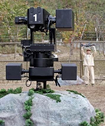
The South Korean SGR-1 sentry robot, a precursor to a fully autonomous weapon, can detect people in the Demilitarized Zone and, if a human grants the command, fire its weapons. The robot is shown here during a test with a surrendering enemy soldier. © 2007 Kim Dong-Joo/AFP/Getty Images
From there, human soldiers can communicate with the individual identified and decide whether to fire the robot sentry’s 5.5mm machine gun or 40mm automatic grenade launcher. The SGR-1’s sensors can detect people two miles away during the day and one mile away at night. Its guns can hit targets two miles away. At present, the sentry has autonomous surveillance capabilities, but it cannot fire without a human command. The journal of the Institute of Electrical and Electronics Engineers reported, however, “[T]he robot does have an automatic mode, in which it can make the decision.”The Israel Defense Forces (IDF) has deployed Sentry Tech systems along Israel’s 60 kilometer border with Gaza. The sentry detects movement and sends signals to a facility “at a distant location.” Soldiers then evaluate the data and decide whether to fire at the target. The Sentry Tech currently has a 12.7mm or a .50 caliber machine gun with a kill zone of about 1 to 1.5 kilometers.To increase its range to several kilometers, the IDF is considering adding anti-armor missiles.Sentry Tech is reportedly designed to defend against people trying to cross the border as well as sniper and rocket attacks. In 2007, Jane’s Defence Weekly described Sentry Tech as “revolutionary” because it could not only detect threats but also engage them. While the system is currently operated by remote control, an IDF division commander told Defense News: “[A]t least in the initial phases of deployment, we’re going to have to keep the man in the loop.” The commander thus implied that human involvement may not always be the case.
Israel has also deployed the Guardium, “a semi-autonomous unmanned ground system,” which is reportedly used for patrolling Israel’s border with Gaza. It can carry lethal or non-lethal payloads. According to the manufacturer G-NIUS’s brochure, “[t]he Guardium UGV™ was designed to perform routine missions, such as programmed patrols along border routes, but also to autonomously react to unscheduled events, in line with a set of guidelines specifically programmed for the site characteristics and security doctrine.” While the brochure implies there is some level of human oversight because it refers to stationary, mobile, and portable control terminals, it also notes that the Guardium can have “autonomous mission execution.”
Unmanned aircraft are moving beyond existing drones to have greater autonomy. The US Navy has commissioned the X-47B, which will be able to take off from and land on an aircraft carrier and refuel on its own power. It was tested multiple times in 2012 and is scheduled in 2013 to do a trial landing on a carrier, “one of aviation’s most difficult maneuvers.” Although as a prototype it will not carry weapons, it has reportedly been designed for eventual “combat purposes,” and it has two weapons bays with a total payload capacity of 4,500 pounds. Humans remain on the loop for the time being, but their role in the flight of the X-47B is limited. Northrop Grumman described it as a system that “takes off, flies a preprogrammed mission, and then returns to base in response to mouse clicks from its mission operator. The mission operator monitors the X-47B air vehicle’s operation, but does not actively ‘fly’ it via remote control as is the case for other unmanned systems currently in operation.” The Los Angeles Times called it “a paradigm shift in warfare, one that is likely to have far-reaching consequences. With the drone’s ability to be flown autonomously by onboard computers, it could usher in an era when death and destruction can be dealt by machines operating semi-independently.”
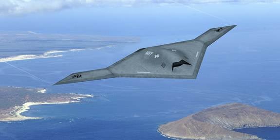
The US Navy’s X-47B, currently undergoing testing, has been commissioned to fly with greater autonomy than existing drones. While the prototype will not carry weapons, it has two weapons bays that could make later models serve a combat function. Photograph by DARPA.
The United Kingdom unveiled a prototype of its Taranis combat aircraft in 2010. Designers described it as “an autonomous and stealthy unmanned aircraft” that aims to strike “targets with real precision at long range, even in another continent.” Because Taranis is only a prototype, it is not armed, but it includes two weapons bays and could eventually carry bombs or missiles. Similar to existing drones, Taranis would presumably be designed to launch attacks against persons as well as materiel. It would also be able to defend itself from enemy aircraft. At this point, the Taranis is expected to retain a human in the loop. The UK Ministry of Defence stated, “Should such systems enter into service, they will at all times be under the control of highly trained military crews on the ground.”Asked if the Taranis would one day choose its own targets, Royal Air Force Air Chief Marshal Simon Bryant responded, “This is a very sensitive area we are paying a lot of attention to.” He thus left the door open to the possibility of greater autonomy in the future.
The United Kingdom’s Taranis combat aircraft, whose prototype was unveiled in 2010, is designed to strike distant targets, “even in another continent.” While the Ministry of Defence has stated that humans will remain in the loop, the Taranis exemplifies the move toward increased autonomy. © 2010 Associated Press
Other countries have also developed or procured unmanned aircraft that are precursors to fully autonomous weapons. The Israeli Harpy, for example, has been described as a combination of an unmanned aerial vehicle and a cruise missile. It is designed to fly “autonomously to the patrol area.” Once there, it seeks to detect hostile radar signals and then destroy a target with a high explosive warhead.The US military’s SWARMS technology would also involve autonomous aircraft, but in this case, many such aircraft would navigate in a synchronized way with a human controller directing them as a group “swarm” rather than individually. While initially designed to gather intelligence,SWARMS could one day undertake offensive operations. For example, their numbers, designed to be a force multiplier, could overwhelm an air defense system.At least at this point, designers envision that SWARMS would have a human on the loop. Tests done in August 2012 showed that a single “operator on the ground, using only a laptop and a military radio, can command an unmanned aerial vehicle (UAV) ‘swarm.’” The ability of a single operator to have effective oversight of dozens or even hundreds of aircraft seems implausible to many experts. As a result, a swarm could operate as a de facto out-of-the-loop weapon.
Because humans still retain control over the decisions to use lethal force, the above weapons systems are not, at least yet, fully autonomous, but they are moving rapidly in that direction. Human oversight is minimal, especially in the case of SWARMS. At the same time, technology is developing that allows weapons to identify targets and travel to and around a battle zone on their own power. Proponents tout military advantages, such as a reduction in the number of human troops required for military operations, the availability of sentries not influenced by laziness or fear, and faster response time. Technological developments combined with these advantages of autonomy create incentives for states to develop weapons with greater autonomy.
Critics have two major concerns, however. First, they question the effectiveness of the existing limited human oversight. Second, they worry that the next step will be to grant these systems control over launching attacks. Speaking of Taranis, for example, Sharkey, a computer scientist and vocal critic of fully autonomous weapons, said, “But warning bells ring for me when they talk about Taranis being ‘a fully autonomous intelligent system’ together with applications in ‘deep missions’ and having a ‘deep target attack’ capability…. We need to know if this means the robot planes will choose their own targets and destroy them—because they certainly will not have the intelligence to discriminate between civilians and combatants.” Control systems specialist Nick Jennings did not object to SWARMS technology as a surveillance tool, but he warned, “We don’t want UAVs selecting targets and working out how best to carry out an attack.” Full autonomy would give weapons this power to decide when to fire.
Given that some believe that full autonomy could become a reality within 20 or 30 years, it is essential to consider the implications of the technology as soon as possible. Both supporters and skeptics have agreed on this point. The UK Ministry of Defence wrote, “[I]f we wish to allow systems to make independent decisions without human intervention, some considerable work will be required to show how such systems will operate legally.” Philip Alston, when serving as the UN special rapporteur on extrajudicial, summary or arbitrary executions, warned that “[u]rgent consideration needs to be given to the legal, ethical and moral implications of the development and use of robot technologies, especially but not limited to uses for warfare.” The rest of this report will explore these implications, particularly as they relate to the protection of civilians during times of armed conflict.
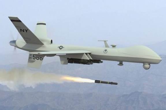
While international legal standards encourage states to review new weapon systems for their compliance with international law, the United States said it did not need to review the newly weaponized Predator drone, shown here firing a Hellfire missile. It argued that the drone and missile had already received approval separately, at a time when the Predator was used for surveillance. © Pan-African News
Reviews should also be sensitive to the fact that some robotic technology, while not inherently harmful, has the potential one day to be weaponized. As soon as such robots are weaponized, states should initiate their regular, rigorous review process. It would be even better to review this technology before weaponization to ensure that robots do not get to that stage, especially since states are more reluctant to give up weapons later in the development process
Tidak ada komentar:
Posting Komentar