POWER equal to princip on winner entering restability as like the record technic generator digital , processor and controller

xample : Advanced Analog & Digital Electronic Design
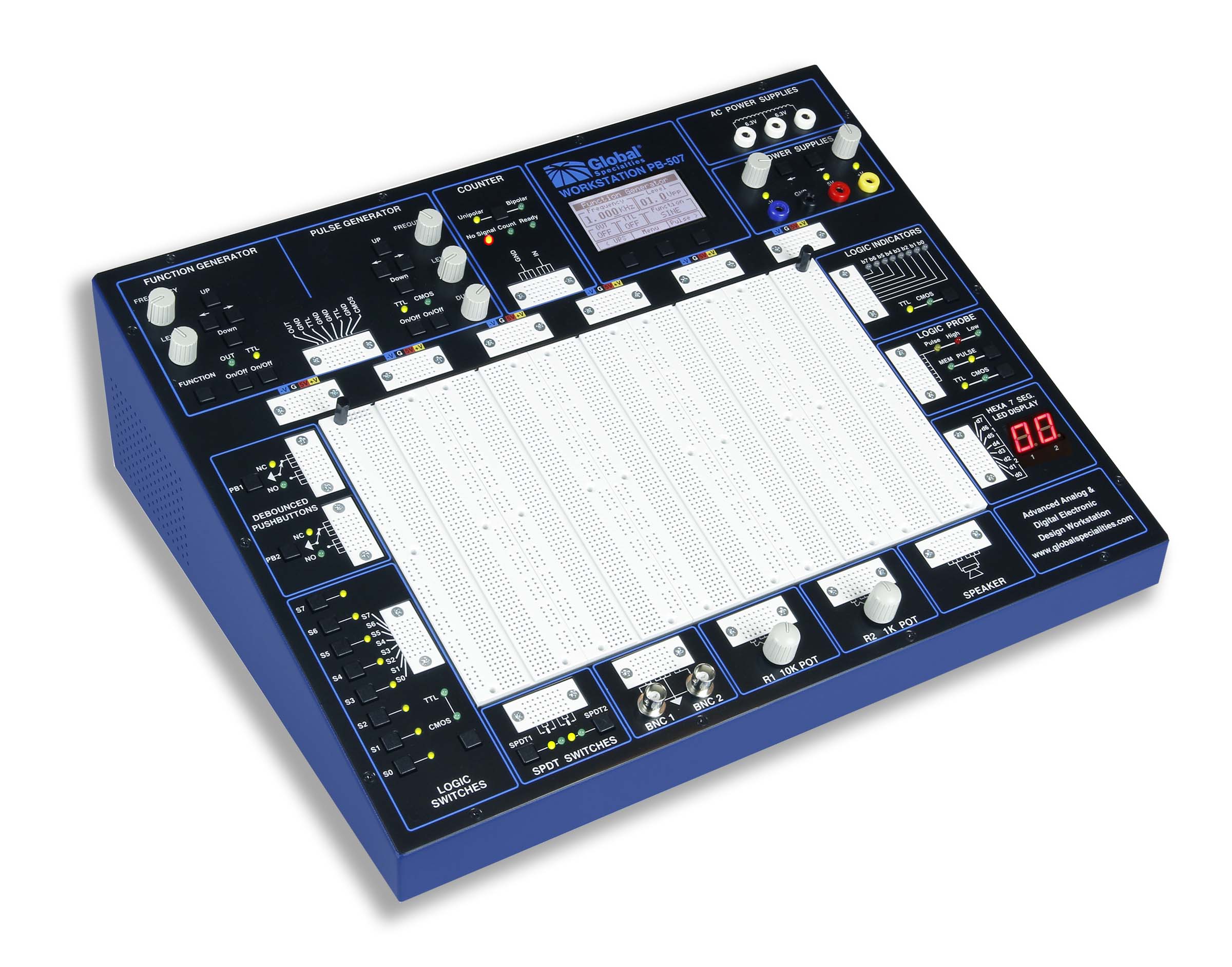
the picture is a powerful, versatile tool for circuit designers, engineers, technicians . Using this feature in can project the controls to a large viewing screen for your classroom to observe and follow along. the picture has an LCD that displays the settings for the active module selected. Simply touch a control element and the LCD switches to that module and displays its settings.


X . I
Power inverter and inverter technology
A power inverter, or inverter, is an electronic device or circuitry that changes direct current (DC) to alternating current (AC).
The input voltage, output voltage and frequency, and overall power handling depend on the design of the specific device or circuitry. The inverter does not produce any power; the power is provided by the DC source.
A power inverter can be entirely electronic or may be a combination of mechanical effects (such as a rotary apparatus) and electronic circuitry. Static inverters do not use moving parts in the conversion process.
Input and output
Input voltage
A typical power inverter device or circuit requires a relatively stable DC power source capable of supplying enough current for the intended power demands of the system. The input voltage depends on the design and purpose of the inverter. Examples include:- 12 VDC, for smaller consumer and commercial inverters that typically run from a rechargeable 12 V lead acid battery or automotive electrical outlet.
- 24, 36 and 48 VDC, which are common standards for home energy systems.
- 200 to 400 VDC, when power is from photovoltaic solar panels.
- 300 to 450 VDC, when power is from electric vehicle battery packs in vehicle-to-grid systems.
- Hundreds of thousands of volts, where the inverter is part of a high-voltage direct current power transmission system.
Output waveform
An inverter can produce a square wave, modified sine wave, pulsed sine wave, pulse width modulated wave (PWM) or sine wave depending on circuit design. The two dominant commercialized waveform types of inverters as of 2007 are modified sine wave and sine wave.There are two basic designs for producing household plug-in voltage from a lower-voltage DC source, the first of which uses a switching boost converter to produce a higher-voltage DC and then converts to AC. The second method converts DC to AC at battery level and uses a line-frequency transformer to create the output voltage.

Square wave
This is one of the simplest waveforms an inverter design can produce and is best suited to low-sensitivity applications such as lighting and heating. Square wave output can produce "humming" when connected to audio equipment and is generally unsuitable for sensitive electronics.
Sine wave
A power inverter device which produces a multiple step sinusoidal AC waveform is referred to as a sine wave inverter. To more clearly distinguish the inverters with outputs of much less distortion than the modified sine wave (three step) inverter designs, the manufacturers often use the phrase pure sine wave inverter. Almost all consumer grade inverters that are sold as a "pure sine wave inverter" do not produce a smooth sine wave output at all, just a less choppy output than the square wave (two step) and modified sine wave (three step) inverters. However, this is not critical for most electronics as they deal with the output quite well.Where power inverter devices substitute for standard line power, a sine wave output is desirable because many electrical products are engineered to work best with a sine wave AC power source. The standard electric utility provides a sine wave, typically with minor imperfections but sometimes with significant distortion.
Sine wave inverters with more than three steps in the wave output are more complex and have significantly higher cost than a modified sine wave, with only three steps, or square wave (one step) types of the same power handling. Switch-mode power supply (SMPS) devices, such as personal computers or DVD players, function on quality modified sine wave power. AC motors directly operated on non-sinusoidal power may produce extra heat, may have different speed-torque characteristics, or may produce more audible noise than when running on sinusoidal power.
Modified sine wave
The modified sine wave output of such an inverter is the sum of two square waves one of which is phase shifted 90 degrees relative to the other. The result is three level waveform with equal intervals of zero volts; peak positive volts; zero volts; peak negative volts and then zero volts. This sequence is repeated. The resultant wave very roughly resembles the shape of a sine wave. Most inexpensive consumer power inverters produce a modified sine wave rather than a pure sine wave.The waveform in commercially available modified-sine-wave inverters resembles a square wave but with a pause during the polarity reversal. Switching states are developed for positive, negative and zero voltages. Generally, the peak voltage to RMS voltage ratio does not maintain the same relationship as for a sine wave. The DC bus voltage may be actively regulated, or the "on" and "off" times can be modified to maintain the same RMS value output up to the DC bus voltage to compensate for DC bus voltage variations.
The ratio of on to off time can be adjusted to vary the RMS voltage while maintaining a constant frequency with a technique called pulse width modulation (PWM). The generated gate pulses are given to each switch in accordance with the developed pattern to obtain the desired output. Harmonic spectrum in the output depends on the width of the pulses and the modulation frequency. When operating induction motors, voltage harmonics are usually not of concern; however, harmonic distortion in the current waveform introduces additional heating and can produce pulsating torques.[4]
Numerous items of electric equipment will operate quite well on modified sine wave power inverter devices, especially loads that are resistive in nature such as traditional incandescent light bulbs. Items with a switch-mode power supply operate almost entirely without problems, but if the item has a mains transformer, this can overheat depending on how marginally it is rated.
However, the load may operate less efficiently owing to the harmonics associated with a modified sine wave and produce a humming noise during operation. This also affects the efficiency of the system as a whole, since the manufacturer's nominal conversion efficiency does not account for harmonics. Therefore, pure sine wave inverters may provide significantly higher efficiency than modified sine wave inverters.
Most AC motors will run on MSW inverters with an efficiency reduction of about 20% owing to the harmonic content. However, they may be quite noisy. A series LC filter tuned to the fundamental frequency may help.
A common modified sine wave inverter topology found in consumer power inverters is as follows: An onboard microcontroller rapidly switches on and off power MOSFETs at high frequency like ~50 kHz. The MOSFETs directly pull from a low voltage DC source (such as a battery). This signal then goes through step-up transformers (generally many smaller transformers are placed in parallel to reduce the overall size of the inverter) to produce a higher voltage signal. The output of the step-up transformers then gets filtered by capacitors to produce a high voltage DC supply. Finally, this DC supply is pulsed with additional power MOSFETs by the microcontroller to produce the final modified sine wave signal.
Other waveforms
By definition there is no restriction on the type of AC waveform an inverter might produce that would find use in a specific or special application.Output frequency
The AC output frequency of a power inverter device is usually the same as standard power line frequency, 50 or 60 hertzIf the output of the device or circuit is to be further conditioned (for example stepped up) then the frequency may be much higher for good transformer efficiency.
Output voltage
The AC output voltage of a power inverter is often regulated to be the same as the grid line voltage, typically 120 or 240 VAC at the distribution level, even when there are changes in the load that the inverter is driving. This allows the inverter to power numerous devices designed for standard line power.Some inverters also allow selectable or continuously variable output voltages.
Output power
A power inverter will often have an overall power rating expressed in watts or kilowatts. This describes the power that will be available to the device the inverter is driving and, indirectly, the power that will be needed from the DC source. Smaller popular consumer and commercial devices designed to mimic line power typically range from 150 to 3000 watts.Not all inverter applications are solely or primarily concerned with power delivery; in some cases the frequency and or waveform properties are used by the follow-on circuit or device.
Batteries
The runtime of an inverter is dependent on the battery power and the amount of power being drawn from the inverter at a given time. As the amount of equipment using the inverter increases, the runtime will decrease. In order to prolong the runtime of an inverter, additional batteries can be added to the inverter.When attempting to add more batteries to an inverter, there are two basic options for installation:
- Series configuration
- If the goal is to increase the overall voltage of the inverter, one can daisy chain batteries in a series configuration. In a series configuration, if a single battery dies, the other batteries will not be able to power the load.
- Parallel configuration
- If the goal is to increase capacity and prolong the runtime of the inverter, batteries can be connected in parallel. This increases the overall ampere-hour (Ah) rating of the battery set.
If a single battery is discharged though, the other batteries will then discharge through it. This can lead to rapid discharge of the entire pack, or even an over-current and possible fire. To avoid this, large paralleled batteries may be connected via diodes or intelligent monitoring with automatic switching to isolate an under-voltage battery from the others.
Applications
DC power source usage

Uninterruptible power supplies
An uninterruptible power supply (UPS) uses batteries and an inverter to supply AC power when mains power is not available. When mains power is restored, a rectifier supplies DC power to recharge the batteries.Electric motor speed control
Inverter circuits designed to produce a variable output voltage range are often used within motor speed controllers. The DC power for the inverter section can be derived from a normal AC wall outlet or some other source. Control and feedback circuitry is used to adjust the final output of the inverter section which will ultimately determine the speed of the motor operating under its mechanical load. Motor speed control needs are numerous and include things like: industrial motor driven equipment, electric vehicles, rail transport systems, and power tools. (See related: variable-frequency drive ) Switching states are developed for positive, negative and zero voltages as per the patterns given in the switching Table 1.The generated gate pulses are given to each switch in accordance with the developed pattern and thus the output is obtained.In refrigeration compressors
An inverter can be used to control the speed of the compressor motor to drive variable refrigerant flow in a refrigeration or air conditioning system to regulate system performance. Such installations are known as inverter compressors. Traditional methods of refrigeration regulation use single-speed compressors switched on and off periodically; inverter-equipped systems have a variable-frequency drive that control the speed of the motor and thus the compressor and cooling output. The variable-frequency AC from the inverter drives a brushless or induction motor, the speed of which is proportional to the frequency of the AC it is fed, so the compressor can be run at variable speeds—eliminating compressor stop-start cycles increases efficiency. A microcontroller typically monitors the temperature in the space to be cooled, and adjusts the speed of the compressor to maintain the desired temperature. The additional electronics and system hardware add cost to the equipment, but can result in substantial savings in operating costs.Power grid
Grid-tied inverters are designed to feed into the electric power distribution system. They transfer synchronously with the line and have as little harmonic content as possible. They also need a means of detecting the presence of utility power for safety reasons, so as not to continue to dangerously feed power to the grid during a power outage.Solar

Induction heating
Inverters convert low frequency main AC power to higher frequency for use in induction heating. To do this, AC power is first rectified to provide DC power. The inverter then changes the DC power to high frequency AC power. Due to the reduction in the number of DC sources employed, the structure becomes more reliable and the output voltage has higher resolution due to an increase in the number of steps so that the reference sinusoidal voltage can be better achieved. This configuration has recently become very popular in AC power supply and adjustable speed drive applications. This new inverter can avoid extra clamping diodes or voltage balancing capacitors.There are three kinds of level shifted modulation techniques, namely:
- Phase Opposition Disposition (POD)
- Alternative Phase Opposition Disposition (APOD)
- Phase Disposition (PD)
HVDC power transmission
With HVDC power transmission, AC power is rectified and high voltage DC power is transmitted to another location. At the receiving location, an inverter in a static inverter plant converts the power back to AC. The inverter must be synchronized with grid frequency and phase and minimize harmonic generation.Electroshock weapons
Electroshock weapons and tasers have a DC/AC inverter to generate several tens of thousands of V AC out of a small 9 V DC battery. First the 9 V DC is converted to 400–2000 V AC with a compact high frequency transformer, which is then rectified and temporarily stored in a high voltage capacitor until a pre-set threshold voltage is reached. When the threshold (set by way of an airgap or TRIAC) is reached, the capacitor dumps its entire load into a pulse transformer which then steps it up to its final output voltage of 20–60 kV. A variant of the principle is also used in electronic flash and bug zappers, though they rely on a capacitor-based voltage multiplier to achieve their high voltage.Miscellaneous
Typical applications for power inverters include:- Portable consumer devices that allow the user to connect a battery, or set of batteries, to the device to produce AC power to run various electrical items such as lights, televisions, kitchen appliances, and power tools.
- Use in power generation systems such as electric utility companies or solar generating systems to convert DC power to AC power.
- Use within any larger electronic system where an engineering need exists for deriving an AC source from a DC source.
Circuit description

Top: Simple inverter circuit shown with an electromechanical switch
and automatic equivalent
auto-switching device implemented with two transistors and split winding auto-transformer in place of the mechanical switch.
and automatic equivalent
auto-switching device implemented with two transistors and split winding auto-transformer in place of the mechanical switch.

Basic design
In one simple inverter circuit, DC power is connected to a transformer through the center tap of the primary winding. A switch is rapidly switched back and forth to allow current to flow back to the DC source following two alternate paths through one end of the primary winding and then the other. The alternation of the direction of current in the primary winding of the transformer produces alternating current (AC) in the secondary circuit.The electromechanical version of the switching device includes two stationary contacts and a spring supported moving contact. The spring holds the movable contact against one of the stationary contacts and an electromagnet pulls the movable contact to the opposite stationary contact. The current in the electromagnet is interrupted by the action of the switch so that the switch continually switches rapidly back and forth. This type of electromechanical inverter switch, called a vibrator or buzzer, was once used in vacuum tube automobile radios. A similar mechanism has been used in door bells, buzzers and tattoo machines.
As they became available with adequate power ratings, transistors and various other types of semiconductor switches have been incorporated into inverter circuit designs. Certain ratings, especially for large systems (many kilowatts) use thyristors (SCR). SCRs provide large power handling capability in a semiconductor device, and can readily be controlled over a variable firing range.
The switch in the simple inverter described above, when not coupled to an output transformer, produces a square voltage waveform due to its simple off and on nature as opposed to the sinusoidal waveform that is the usual waveform of an AC power supply. Using Fourier analysis, periodic waveforms are represented as the sum of an infinite series of sine waves. The sine wave that has the same frequency as the original waveform is called the fundamental component. The other sine waves, called harmonics, that are included in the series have frequencies that are integral multiples of the fundamental frequency.
Fourier analysis can be used to calculate the total harmonic distortion (THD). The total harmonic distortion (THD) is the square root of the sum of the squares of the harmonic voltages divided by the fundamental voltage:

Advanced designs

The issue of waveform quality can be addressed in many ways. Capacitors and inductors can be used to filter the waveform. If the design includes a transformer, filtering can be applied to the primary or the secondary side of the transformer or to both sides. Low-pass filters are applied to allow the fundamental component of the waveform to pass to the output while limiting the passage of the harmonic components. If the inverter is designed to provide power at a fixed frequency, a resonant filter can be used. For an adjustable frequency inverter, the filter must be tuned to a frequency that is above the maximum fundamental frequency.
Since most loads contain inductance, feedback rectifiers or antiparallel diodes are often connected across each semiconductor switch to provide a path for the peak inductive load current when the switch is turned off. The antiparallel diodes are somewhat similar to the freewheeling diodes used in AC/DC converter circuits.
| Waveform | Signal transitions per period | Harmonics eliminated | Harmonics amplified | System description | THD |
|---|---|---|---|---|---|
 | 2 | 2-level square wave | ~45%[9] | ||
 | 4 | 3, 9, 27, … | 3-level modified sine wave | >23.8%[9] | |
 | 8 | 5-level modified sine wave | >6.5%[9] | ||
 | 10 | 3, 5, 9, 27 | 7, 11, … | 2-level very slow PWM | |
 | 12 | 3, 5, 9, 27 | 7, 11, … | 3-level very slow PWM |
Changing the square wave as described above is an example of pulse-width modulation (PWM). Modulating, or regulating the width of a square-wave pulse is often used as a method of regulating or adjusting an inverter's output voltage. When voltage control is not required, a fixed pulse width can be selected to reduce or eliminate selected harmonics. Harmonic elimination techniques are generally applied to the lowest harmonics because filtering is much more practical at high frequencies, where the filter components can be much smaller and less expensive. Multiple pulse-width or carrier based PWM control schemes produce waveforms that are composed of many narrow pulses. The frequency represented by the number of narrow pulses per second is called the switching frequency or carrier frequency. These control schemes are often used in variable-frequency motor control inverters because they allow a wide range of output voltage and frequency adjustment while also improving the quality of the waveform.
Multilevel inverters provide another approach to harmonic cancellation. Multilevel inverters provide an output waveform that exhibits multiple steps at several voltage levels. For example, it is possible to produce a more sinusoidal wave by having split-rail direct current inputs at two voltages, or positive and negative inputs with a central ground. By connecting the inverter output terminals in sequence between the positive rail and ground, the positive rail and the negative rail, the ground rail and the negative rail, then both to the ground rail, a stepped waveform is generated at the inverter output. This is an example of a three level inverter: the two voltages and ground.
More on achieving a sine wave
Resonant inverters produce sine waves with LC circuits to remove the harmonics from a simple square wave. Typically there are several series- and parallel-resonant LC circuits, each tuned to a different harmonic of the power line frequency. This simplifies the electronics, but the inductors and capacitors tend to be large and heavy. Its high efficiency makes this approach popular in large uninterruptible power supplies in data centers that run the inverter continuously in an "online" mode to avoid any switchover transient when power is lost. (See related: Resonant inverter)A closely related approach uses a ferroresonant transformer, also known as a constant voltage transformer, to remove harmonics and to store enough energy to sustain the load for a few AC cycles. This property makes them useful in standby power supplies to eliminate the switchover transient that otherwise occurs during a power failure while the normally idle inverter starts and the mechanical relays are switching to its output.
Enhanced quantization
A proposal suggested in Power Electronics magazine utilizes two voltages as an improvement over the common commercialized technology, which can only apply DC bus voltage in either direction or turn it off. The proposal adds intermediate voltages to the common design. Each cycle sees the following sequence of delivered voltages: v1, v2, v1, 0, −v1, −v2, −v1.Three-phase inverters
Three-phase inverters are used for variable-frequency drive applications and for high power applications such as HVDC power transmission. A basic three-phase inverter consists of three single-phase inverter switches each connected to one of the three load terminals. For the most basic control scheme, the operation of the three switches is coordinated so that one switch operates at each 60 degree point of the fundamental output waveform. This creates a line-to-line output waveform that has six steps. The six-step waveform has a zero-voltage step between the positive and negative sections of the square-wave such that the harmonics that are multiples of three are eliminated as described above. When carrier-based PWM techniques are applied to six-step waveforms, the basic overall shape, or envelope, of the waveform is retained so that the 3rd harmonic and its multiples are cancelled.

foot bright cloud :
Early inverters
From the late nineteenth century through the middle of the twentieth century, DC-to-AC power conversion was accomplished using rotary converters or motor-generator sets (M-G sets). In the early twentieth century, vacuum tubes and gas filled tubes began to be used as switches in inverter circuits. The most widely used type of tube was the thyratron.The origins of electromechanical inverters explain the source of the term inverter. Early AC-to-DC converters used an induction or synchronous AC motor direct-connected to a generator (dynamo) so that the generator's commutator reversed its connections at exactly the right moments to produce DC. A later development is the synchronous converter, in which the motor and generator windings are combined into one armature, with slip rings at one end and a commutator at the other and only one field frame. The result with either is AC-in, DC-out. With an M-G set, the DC can be considered to be separately generated from the AC; with a synchronous converter, in a certain sense it can be considered to be "mechanically rectified AC". Given the right auxiliary and control equipment, an M-G set or rotary converter can be "run backwards", converting DC to AC. Hence an inverter is an inverted converter.
Controlled rectifier inverters
Since early transistors were not available with sufficient voltage and current ratings for most inverter applications, it was the 1957 introduction of the thyristor or silicon-controlled rectifier (SCR) that initiated the transition to solid state inverter circuits.The commutation requirements of SCRs are a key consideration in SCR circuit designs. SCRs do not turn off or commutate automatically when the gate control signal is shut off. They only turn off when the forward current is reduced to below the minimum holding current, which varies with each kind of SCR, through some external process. For SCRs connected to an AC power source, commutation occurs naturally every time the polarity of the source voltage reverses. SCRs connected to a DC power source usually require a means of forced commutation that forces the current to zero when commutation is required. The least complicated SCR circuits employ natural commutation rather than forced commutation. With the addition of forced commutation circuits, SCRs have been used in the types of inverter circuits described above.

In applications where inverters transfer power from a DC power source to an AC power source, it is possible to use AC-to-DC controlled rectifier circuits operating in the inversion mode. In the inversion mode, a controlled rectifier circuit operates as a line commutated inverter. This type of operation can be used in HVDC power transmission systems and in regenerative braking operation of motor control systems.
Another type of SCR inverter circuit is the current source input (CSI) inverter. A CSI inverter is the dual of a six-step voltage source inverter. With a current source inverter, the DC power supply is configured as a current source rather than a voltage source. The inverter SCRs are switched in a six-step sequence to direct the current to a three-phase AC load as a stepped current waveform. CSI inverter commutation methods include load commutation and parallel capacitor commutation. With both methods, the input current regulation assists the commutation. With load commutation, the load is a synchronous motor operated at a leading power factor.
As they have become available in higher voltage and current ratings, semiconductors such as transistors or IGBTs that can be turned off by means of control signals have become the preferred switching components for use in inverter circuits.
Rectifier and inverter pulse numbers
Rectifier circuits are often classified by the number of current pulses that flow to the DC side of the rectifier per cycle of AC input voltage. A single-phase half-wave rectifier is a one-pulse circuit and a single-phase full-wave rectifier is a two-pulse circuit. A three-phase half-wave rectifier is a three-pulse circuit and a three-phase full-wave rectifier is a six-pulse circuit.With three-phase rectifiers, two or more rectifiers are sometimes connected in series or parallel to obtain higher voltage or current ratings. The rectifier inputs are supplied from special transformers that provide phase shifted outputs. This has the effect of phase multiplication. Six phases are obtained from two transformers, twelve phases from three transformers and so on. The associated rectifier circuits are 12-pulse rectifiers, 18-pulse rectifiers and so on...
When controlled rectifier circuits are operated in the inversion mode, they would be classified by pulse number also. Rectifier circuits that have a higher pulse number have reduced harmonic content in the AC input current and reduced ripple in the DC output voltage. In the inversion mode, circuits that have a higher pulse number have lower harmonic content in the AC output voltage waveform
X . II
Pulse-width modulation

An example of PWM in an idealized inductor driven by a ■ voltage source modulated as a series of pulses, resulting in a ■ sine-like current in the inductor. The rectangular voltage pulses nonetheless result in a more and more smooth current waveform, as the switching frequency increases. Note that the current waveform is the integral of the voltage waveform.
The average value of voltage (and current) fed to the load is controlled by turning the switch between supply and load on and off at a fast rate. The longer the switch is on compared to the off periods, the higher the total power supplied to the load.
The PWM switching frequency has to be much higher than what would affect the load (the device that uses the power), which is to say that the resultant waveform perceived by the load must be as smooth as possible. The rate (or frequency) at which the power supply must switch can vary greatly depending on load and application, for example
- Switching has to be done several times a minute in an electric stove; 120 Hz in a lamp dimmer; between a few kilohertz (kHz), to tens of kHz for a motor drive; and well into the tens or hundreds of kHz in audio amplifiers and computer power supplies.
The main advantage of PWM is that power loss in the switching devices is very low. When a switch is off there is practically no current, and when it is on and power is being transferred to the load, there is almost no voltage drop across the switch. Power loss, being the product of voltage and current, is thus in both cases close to zero. PWM also works well with digital controls, which, because of their on/off nature, can easily set the needed duty cycle.
PWM has also been used in certain communication systems where its duty cycle has been used to convey information over a communications channel.
Some machines (such as a sewing machine motor) require partial or variable power. In the past, control (such as in a sewing machine's foot pedal) was implemented by use of a rheostat connected in series with the motor to adjust the amount of current flowing through the motor. It was an inefficient scheme, as this also wasted power as heat in the resistor element of the rheostat, but tolerable because the total power was low. While the rheostat was one of several methods of controlling power (see autotransformers and Variac for more info), a low cost and efficient power switching/adjustment method was needed. This mechanism also needed to be able to drive motors for fans, pumps and robotic servos, and needed to be compact enough to interface with lamp dimmers. PWM emerged as a solution for this complex problem.
One early application of PWM was in the Sinclair X10, a 10 W audio amplifier available in kit form in the 1960s. At around the same time PWM started to be used in AC motor control.[2]
Of note, for about a century, some variable-speed electric motors have had decent efficiency, but they were somewhat more complex than constant-speed motors, and sometimes required bulky external electrical apparatus, such as a bank of variable power resistors or rotating converters such as the Ward Leonard drive.
Principle


Fig. 2: A simple method to generate the PWM pulse train corresponding to a given signal is the intersective PWM: the signal (here the red sine wave) is compared with a sawtooth waveform (blue). When the latter is less than the former, the PWM signal (magenta) is in high state (1). Otherwise it is in the low state (0).
Delta
In the use of delta modulation for PWM control, the output signal is integrated, and the result is compared with limits, which correspond to a Reference signal offset by a constant. Every time the integral of the output signal reaches one of the limits, the PWM signal changes state.[3] Figure 3
Delta-sigma
In delta-sigma modulation as a PWM control method, the output signal is subtracted from a reference signal to form an error signal. This error is integrated, and when the integral of the error exceeds the limits, the output changes state. Figure 4
Fig. 4 : Principle of the sigma-delta PWM. The top green waveform is the reference signal, on which the output signal (PWM, in the bottom plot) is subtracted to form the error signal (blue, in top plot). This error is integrated (middle plot), and when the integral of the error exceeds the limits (red lines), the output changes state.
Space vector modulation
Space vector modulation is a PWM control algorithm for multi-phase AC generation, in which the reference signal is sampled regularly; after each sample, non-zero active switching vectors adjacent to the reference vector and one or more of the zero switching vectors are selected for the appropriate fraction of the sampling period in order to synthesize the reference signal as the average of the used vectors.Direct torque control (DTC)
Direct torque control is a method used to control AC motors. It is closely related with the delta modulation (see above). Motor torque and magnetic flux are estimated and these are controlled to stay within their hysteresis bands by turning on new combination of the device's semiconductor switches each time either of the signal tries to deviate out of the band.Time proportioning
Many digital circuits can generate PWM signals (e.g., many microcontrollers have PWM outputs). They normally use a counter that increments periodically (it is connected directly or indirectly to the clock of the circuit) and is reset at the end of every period of the PWM. When the counter value is more than the reference value, the PWM output changes state from high to low (or low to high).[4] This technique is referred to as time proportioning, particularly as time-proportioning control[5] – which proportion of a fixed cycle time is spent in the high state.The incremented and periodically reset counter is the discrete version of the intersecting method's sawtooth. The analog comparator of the intersecting method becomes a simple integer comparison between the current counter value and the digital (possibly digitized) reference value. The duty cycle can only be varied in discrete steps, as a function of the counter resolution. However, a high-resolution counter can provide quite satisfactory performance.
Types

Fig. 5 : Three types of PWM signals (blue): leading edge modulation (top), trailing edge modulation (middle) and centered pulses (both edges are modulated, bottom). The green lines are the sawtooth waveform (first and second cases) and a triangle waveform (third case) used to generate the PWM waveforms using the intersective method.
- The pulse center may be fixed in the center of the time window and both edges of the pulse moved to compress or expand the width.
- The lead edge can be held at the lead edge of the window and the tail edge modulated.
- The tail edge can be fixed and the lead edge modulated.
Spectrum
The resulting spectra (of the three cases) are similar, and each contains a dc component—a base sideband containing the modulating signal and phase modulated carriers at each harmonic of the frequency of the pulse. The amplitudes of the harmonic groups are restricted by a envelope (sinc function) and extend to infinity. The infinite bandwidth is caused by the nonlinear operation of the pulse-width modulator. In consequence, a digital PWM suffers from aliasing distortion that significantly reduce its applicability for modern communications system. By limiting the bandwidth of the PWM kernel, aliasing effects can be avoided.
On the contrary, the delta modulation is a random process that produces continuous spectrum without distinct harmonics.
PWM sampling theorem
The process of PWM conversion is non-linear and it is generally supposed that low pass filter signal recovery is imperfect for PWM. The PWM sampling theorem shows that PWM conversion can be perfect. The theorem states that "Any bandlimited baseband signal within ±0.637 can be represented by a pulsewidth modulation (PWM) waveform with unit amplitude. The number of pulses in the waveform is equal to the number of Nyquist samples and the peak constraint is independent of whether the waveform is two-level or three-level."• Nyquist-Shannon Sampling Theorem: “If you have a signal that is perfectly band limited to a bandwidth of f0 then you can collect all the information there is in that signal by sampling it at discrete times, as long as your sample rate is greater than 2f0.”
Applications
Servos
PWM is used to control servomechanisms; see servo control.Telecommunications
In telecommunications, PWM is a form of signal modulation where the widths of the pulses correspond to specific data values encoded at one end and decoded at the other.Pulses of various lengths (the information itself) will be sent at regular intervals (the carrier frequency of the modulation).
          _      _      _      _      _      _      _      _
         | |    | |    | |    | |    | |    | |    | |    | |
Clock    | |    | |    | |    | |    | |    | |    | |    | |
       __| |____| |____| |____| |____| |____| |____| |____| |____

                 _      __     ____          ____   _
PWM signal      | |    |  |   |    |        |    | | |
                | |    |  |   |    |        |    | | |
       _________| |____|  |___|    |________|    |_| |___________

Data       0     1       2      4      0      4     1      0
The inclusion of a clock signal is not necessary, as the leading edge of the data signal can be used as the clock if a small offset is added to the data value in order to avoid a data value with a zero length pulse. _ __ ___ _____ _ _____ __ _
| | | | | | | | | | | | | | | |
PWM signal | | | | | | | | | | | | | | | |
__| |____| |___| |__| |_| |____| |_| |___| |_____
Data 0 1 2 4 0 4 1 0
Power delivery
PWM can be used to control the amount of power delivered to a load without incurring the losses that would result from linear power delivery by resistive means. Drawbacks to this technique are that the power drawn by the load is not constant but rather discontinuous (see Buck converter), and energy delivered to the load is not continuous either. However, the load may be inductive, and with a sufficiently high frequency and when necessary using additional passive electronic filters, the pulse train can be smoothed and average analog waveform recovered. Power flow into the load can be continuous. Power flow from the supply is not constant and will require energy storage on the supply side in most cases. (In the case of an electrical circuit, a capacitor to absorb energy stored in (often parasitic) supply side inductance.)High frequency PWM power control systems are easily realisable with semiconductor switches. As explained above, almost no power is dissipated by the switch in either on or off state. However, during the transitions between on and off states, both voltage and current are nonzero and thus power is dissipated in the switches. By quickly changing the state between fully on and fully off (typically less than 100 nanoseconds), the power dissipation in the switches can be quite low compared to the power being delivered to the load.
Modern semiconductor switches such as MOSFETs or insulated-gate bipolar transistors (IGBTs) are well suited components for high-efficiency controllers. Frequency converters used to control AC motors may have efficiencies exceeding 98%. Switching power supplies have lower efficiency due to low output voltage levels (often even less than 2 V for microprocessors are needed) but still more than 70–80% efficiency can be achieved.
Variable-speed fan controllers for computers usually use PWM, as it is far more efficient when compared to a potentiometer or rheostat. (Neither of the latter is practical to operate electronically; they would require a small drive motor.)
Light dimmers for home use employ a specific type of PWM control. Home-use light dimmers typically include electronic circuitry which suppresses current flow during defined portions of each cycle of the AC line voltage. Adjusting the brightness of light emitted by a light source is then merely a matter of setting at what voltage (or phase) in the AC half-cycle the dimmer begins to provide electric current to the light source (e.g. by using an electronic switch such as a triac). In this case the PWM duty cycle is the ratio of the conduction time to the duration of the half AC cycle defined by the frequency of the AC line voltage (50 Hz or 60 Hz depending on the country).
These rather simple types of dimmers can be effectively used with inert (or relatively slow reacting) light sources such as incandescent lamps, for example, for which the additional modulation in supplied electrical energy which is caused by the dimmer causes only negligible additional fluctuations in the emitted light. Some other types of light sources such as light-emitting diodes (LEDs), however, turn on and off extremely rapidly and would perceivably flicker if supplied with low frequency drive voltages. Perceivable flicker effects from such rapid response light sources can be reduced by increasing the PWM frequency. If the light fluctuations are sufficiently rapid (faster than the flicker fusion threshold), the human visual system can no longer resolve them and the eye perceives the time average intensity without flicker.
In electric cookers, continuously variable power is applied to the heating elements such as the hob or the grill using a device known as a simmerstat. This consists of a thermal oscillator running at approximately two cycles per minute and the mechanism varies the duty cycle according to the knob setting. The thermal time constant of the heating elements is several minutes, so that the temperature fluctuations are too small to matter in practice.
Voltage regulation
PWM is also used in efficient voltage regulators. By switching voltage to the load with the appropriate duty cycle, the output will approximate a voltage at the desired level. The switching noise is usually filtered with an inductor and a capacitor.One method measures the output voltage. When it is lower than the desired voltage, it turns on the switch. When the output voltage is above the desired voltage, it turns off the switch.
Audio effects and amplification
PWM is sometimes used in sound (music) synthesis, in particular subtractive synthesis, as it gives a sound effect similar to chorus or slightly detuned oscillators played together. (In fact, PWM is equivalent to the difference of two sawtooth waves with one of them inverted.[1] The ratio between the high and low level is typically modulated with a low frequency oscillator. In addition, varying the duty cycle of a pulse waveform in a subtractive-synthesis instrument creates useful timbral variations. Some synthesizers have a duty-cycle trimmer for their square-wave outputs, and that trimmer can be set by ear; the 50% point (true square wave) was distinctive, because even-numbered harmonics essentially disappear at 50%. Pulse waves, usually 50%, 25%, and 12.5%, make up the soundtracks of classic video games.A new class of audio amplifiers based on the PWM principle is becoming popular. Called class-D amplifiers, they produce a PWM equivalent of the analog input signal which is fed to the loudspeaker via a suitable filter network to block the carrier and recover the original audio. These amplifiers are characterized by very good efficiency figures (≥ 90%) and compact size/light weight for large power outputs. For a few decades, industrial and military PWM amplifiers have been in common use, often for driving servo motors. Field-gradient coils in MRI machines are driven by relatively high-power PWM amplifiers.
Historically, a crude form of PWM has been used to play back PCM digital sound on the PC speaker, which is driven by only two voltage levels, typically 0 V and 5 V. By carefully timing the duration of the pulses, and by relying on the speaker's physical filtering properties (limited frequency response, self-inductance, etc.) it was possible to obtain an approximate playback of mono PCM samples, although at a very low quality, and with greatly varying results between implementations.
In more recent times, the Direct Stream Digital sound encoding method was introduced, which uses a generalized form of pulse-width modulation called pulse density modulation, at a high enough sampling rate (typically in the order of MHz) to cover the whole acoustic frequencies range with sufficient fidelity. This method is used in the SACD format, and reproduction of the encoded audio signal is essentially similar to the method used in class-D amplifiers.
Electrical
SPWM (Sine–triangle pulse width modulation) signals are used in micro-inverter design (used in solar and wind power applications). These switching signals are fed to the FETs that are used in the device. The device's efficiency depends on the harmonic content of the PWM signal. There is much research on eliminating unwanted harmonics and improving the fundamental strength, some of which involves using a modified carrier signal instead of a classic sawtooth signal in order to decrease power losses and improve efficiency. Another common application is in robotics where PWM signals are used to control the speed of the robot by controlling the motors.X . III
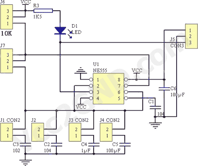
APPLICATION PWM
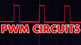
PWM circuits are fun. WE can use them to dim LEDs, control the speed of fans and motors, control the power going to a thermoelectric cooler, or control the power going to pretty much anything you want. Just make sure that you don’t exceed the maximum voltage rating of your device. The video explains it all .


Which need to be considered in making the organizing of digital generator are:
1. 8 bit data if able / electronic digital switch
2. a logic sequencer that matches the function of the coordinates of energy, space and time thorough restability
3. controll (count rolling) = unequivocal spin orbit without slipping despite rapid movement in time and energy supply.
4. 8 bit address if able to support orbit motion slowed and accelerated to super supreme master quickly.
5. The accessed memory is limited to 23 bits if it is capable of delta deleted programs
X . IIII
Inverter for Energy Saving
What's an inverter?
An inverter is energy saving technology that eliminates wasted operation in air conditioners by efficiently controlling motor speed.

Air conditioners maintain set temperature by cooling when room temperature rises above the set temperature and heating when the room temperature falls below the set temperature.
Motor speed in non-inverter type air conditioners remains constant and temperature is adjusted by turning the motor ON and OFF, which consumes more energy.
In inverter type air conditioners, temperature is adjusted by changing motor speed without turning the motor ON and OFF.
Compared to non-inverter type air conditioners, air conditioners with inverters have less power loss and can save 30% more in energy.
When compared with a man running
Non-Inverter Type Air Conditioner
Starting and stopping hard running, resting, then starting and stopping once again uses more energy.
Inverter Type Air Conditioner
When an appropriate pace is maintained, a runner can continue without wasting energy.
How is motor speed controlled?
Motor operates by magnets and electric current.
The motor consist of two types of magnets.
One is a permanent magnet that has a natural magnetic force.
The other is an electromagnet that produces a magnetic force by electricity.
One is a permanent magnet that has a natural magnetic force.
The other is an electromagnet that produces a magnetic force by electricity.

The direction of electric current determines polarity of the electromagnet
The north (N) and south (S) poles of the electromagnet are determined by the direction of electric current.
When the direction of electric current is reversed, the north (N) and south (S) poles are also reversed.
When the direction of electric current is reversed, the north (N) and south (S) poles are also reversed.

The motor rotates by switching direction of electric current.
When magnets come into contact, an attractive force occurs between the N and S poles of the magnets and a repulsive force occurs between the N and N poles and the S and S poles.
The motor rotates from the attractive and repulsive forces caused by the change in polarity of the electromagnet.
The motor rotates from the attractive and repulsive forces caused by the change in polarity of the electromagnet.

The inverter is used to adjust the speed in which the direction of the electric current is switched, and this regulates the rotation speed of the motor.
The inverter rotates the motor by switching the direction of the electric current of the electromagnet.Moreover, regulation of rotation speed in a motor is also performed by meticulously controlling the switching speed.
Of course , and so do I , thankyou for Trutech Products , a feed back give good appreciation and take to awareness , Improvement , Maintenance and connectivity between many subject sains and technology ...Keep Safe and always health Mr/ Mrs ....in trutech Product .
BalasHapus