

The abacus is a deceptively simple calculating tool still used all over the world. It's a useful learning device for the visually impaired, as well as for anyone who wants to learn the roots of the modern calculator. Read these simple steps and get calculating.
Steps

Part 1
Counting and Basics
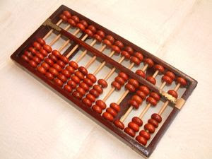
 1Orient the abacus correctly. A basic abacus consists of two rows of beads arranged in a variable number of columns. Each column in the top row should have one or two beads per row, while each column in the bottom row should have four. When you start, all of the beads should be up in the top row, and down in the bottom row. The beads in the top row represent the number value 5 and each bead in the bottom row represents the number value 1.
- Once you become more familiar with the function of the abacus, you can assign different values to the beads in the bottom row to perform more complex operations. The beads in the top row, however, need to be 5 times the value of each bead in the bottom row for the abacus method to work.
 2Assign each column a place value. As on a modern calculator, each column of beads represents a "place" value from which you build a numeral. So, the farthest column on the right would be the "ones" place (1-9), the second farthest the "tens" place (10-99), the third farthest the hundreds (100-999), and so on.
- Depending on your calculation, you can also assign a decimal place that you'll need to keep track of. If you want to enter the number 12,345.67, the 7 would be in the first column, the 6 in the second, the 5 in the third, and so on. When doing those calculations, you just have to remember where the decimal place is, mark it on the abacus with a pencil, or you can skip a row and leave it "blank" if that helps you remember.
 3Start counting. To count a digit, push one bead to the "up" position. "One" would be represented by pushing a single bead from the bottom row in the farthest column on the right to the "up" position, "two" by pushing two, etc.
 4Complete the "4/5 exchange."[1] Since there are only four beads on the bottom row, to go from "four" to "five," you push the bead on the top row to the "down" position and push all four beads from the bottom row down. The abacus at this position is correctly read "five." To count "six," push one bead from the bottom row up, so the bead in the top row is down (representing a value of 5) and one bead from the bottom row is up.
- The process is essentially the same across the abacus. Go from "nine," in which all the beads in the ones place are pushed up and the bead in the top row is pushed down, to "ten," in which a single bead from the bottom row of the tens place is pushed up.
- So, to illustrate: 12345 would be represented with the top bead down in the ones place, four beads from the bottom row of the tens place pushed up, three beads up in the bottom row of the hundreds place, two beads up in the bottom row of the thousands, and a single bead from the bottom row of the ten-thousand place.
- It's easy to forget to push the beads in the bottom row down when exchanging a place, making the board will show the wrong value. It's easy enough to keep track of when you're counting, but when you get into complicated arithmetic it becomes more difficult.


Part 2
Adding and Subtracting
 1Input your first number. Say you've got to add 1234 and 5678. Enter 1234 on the abacus by pushing up four beads in the ones place, three in the tens place, two in the hundreds place, and one in the thousands place.
 2Start adding from the left. Unlike traditional arithmetic, in which you'd start from the ones column and move left, the abacus works from left to right. So, the first numbers you'll add are the 1 and the 5 from the thousands place, in this case moving the single bead from the top row of that column down to add the 5, and leaving the lower bead up for a total of 6. Likewise, you'll move the top bead in the hundreds place down and three more beads from the bottom up to get an 8 in the hundreds place.
 3Complete an exchange. Here's where things get creative. Since adding the two numbers in the tens place will result in 10, you'll carry over a 1 to the hundred place, making it a 9 in that column. Next, put all the beads down in the tens place, leaving it zero.
- In the ones column, you'll do essentially the same thing. 8 + 4 = 12, so you'll carry the one over to the tens place, making it 1, leaving you with 2 in the ones place.
 4Count up your beads. You're left with a 6 in the thousands column, a 9 in the hundreds, a 1 in the tens, and a 2 in the ones: 1,234 + 5,678 = 6,912.
 5To subtract, do essentially the exact same process in reverse. Borrow digits from the previous column instead of carrying them over. Say you're subtracting 867 from 932. After entering 932 into the abacus (the upper bead in the up position and all four lower beads up in the hundreds column, three lower beads up in the tens column, and two lower beads up in the ones column), start subtracting column-by-column starting on your left.
- 8 from 9 is one, so you'll leave a single bead up in the hundreds place. In the tens place, you can't subtract 6 from 3, so you'll borrow the 1 in the hundreds place (leaving it zero) and subtract 6 from 13, making it 7 in the tens place (the upper bead up and two lower beads). Do the same thing in the ones place, "borrowing" a bead from the tens place (making it 6) to subtract 7 from 12 instead of 2. There should be a 5 in the ones column: 932 - 867 = 65.


Part 3
 Multiplying
 1Transpose the problem onto the abacus.[2] Unlike adding, it helps to start at the farthest left column of the abacus when multiplying. Say you're multiplying 34 and 12. You need to assign columns to "3" "4" "X" "1" "2" "=" and leave the rest of the columns to the right of them blank for your product. For this problem, you'll need at least three.
- The "X" and the "=" should just be spaces that you leave blank, to keep your numbers separate, so it will take a total of six columns to enter "34 x 12 =" into the abacus.
- The abacus should have 3 beads up in the farthest column left, four up in the next farthest, a blank column, one bead up, two beads up, another blank column, and at least three columns open to record the product.
 2Multiply by alternating columns. The order here is critical. You need to multiply the first column by the first column after the break, then the first column by the second column after the break. Next, you'll multiply the second column before the break by the first column after the break, then the second column before the break by the second column after the break. It should always be done in this order.


3
Record the products in the correct order. First, you'll multiply 3 and 1, recording their product in the first answer column, which in this case will be the seventh column from the left, accounting for each digit and each necessary blank column. Push three beads up in that seventh column. Next, multiply the 3 and the 2, recording their product in the eighth column. Push up the upper bead and one lower bead in that column.
- Here's where it gets tricky. When you multiply the 4 and the 1, you'll need to add that product to the eighth column, the second of the answer columns. The product of 4 and 1 is 4, and since you're adding a 4 to a 6 in that column, you'll need to carry one bead over to the first answer column, making it a 4 in the seventh column and a zero in the eighth.
- Multiply the last two digits in the problem, 4 and 2, and record that product in the ninth column, putting an 8 in the last of the answer columns, which should now read 4, blank, and 8, making your answer 408.
Part 4
 Dividing
 1To divide, leave space for the answer between the divisor and the dividend.[3] Division is a more fluid process than multiplication, and it works best when you don't leave blank spaces between the numbers involved.The left-most column on the abacus will be the divisor, the number being divided by. The next spaces to the right should be left for the answer.
- Say you're dividing 34 by 2. You know the answer will be at least two columns, so leave two columns between 2 on the right and the 3 and the 4.
- To summarize, to enter 34 divided by 2 on the abacus, you should have 2 in the left most column, two columns to record the answer, the 3 in the fourth column, and the 4 in the fifth.
 2Record the quotient. Take the first number in the dividend (3) and the divisor (2) in the first answer column. 2 goes into 3 once, so record a 1 in column 2.
 3Determine the remainder. Next, you need to multiply the quotient in column two (1) by the dividend in column one (2) to determine the remainder. This product (2) needs to be subtracted from column four. The divisor should now read 14.
 4Repeat the process. Record the next digit of the quotient in the third column, subtracting the product from the divisor (here, eliminating it). Your board should now read 2, 1, 7, leaving your dividend and the quotient, 17.


Abacus Basics
Slide all beads to the outer edge of their columns, so no beads are touching the center bar.Use each column of the abacus to represent one digit in the number being calculated, so the right-most column in a zero decimal number is the ones column, the next column to the left is the tens column, and so on.
Slide one bead up from the bottom column to the median bar for the current digit to mark one, two beads to mark two, and so on up to four.
Slide all four beads in the lower section down, and move a bead from the top of the same column to the median to represent five.
Slide beads from the bottom up, while keeping the five at the median, to represent six through nine.
Slide all beads in a row away from the median, then slide one bead in the row to its left to the median to carry over a number.
Adding and Subtracting
Slide the beads of the abacus to represent the first number in the calculation.Slide one additional bead to the median in the right-most column for the value of the number being added, or slide one bead away for the number being subtracted. For example, if the ones digit of the first number is six, and the ones digit of the second number is two, you would add two by sliding two beads up in the lower right column, leaving you with the five bead and three ones. To subtract two, slide the bottom bead down, then slide the top bead away from the median and the four bottom beads back to the median to yield four.
Perform any carryover required by the calculation. For example, if adding three to seven for a digit, you would slide two beads up, find that you are out of beads to slide, then push all beads in the current row away from the median, while adding a single bead to the column to its left.
Perform reverse carryover, or borrowing, for subtraction if the number being subtracted in the current digit is larger than the value of the digit in the first number. For example to subtract seven from zero in a column, move one bead in the column to the left away from the median, then all the beads in the current column to the median, then complete by subtracting the remaining six beads as normal.
Repeat for each column until you reach the left-most column.
To perform decimal calculations on a hexadecimal abacus, simply ignore the top bead from the top row and bottom bead in the bottom row for each column.


Using an Abacus and the Counting Method
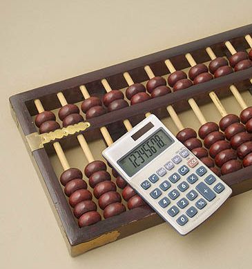
Parents of many children with visual impairments are familiar with "talking calculators" and understand how their child can use this adaptive device to aid him/her in doing math problems. However, there is an ancient device they may not be aware of that is very important for their child to be able to use. This device is an abacus and is an adaptation of the Japanese abacus. Most of you have seen an abacus somewhere in your life, but you may never have used one. For the child with a visual impairment the abacus is comparable to the sighted child's pencil and paper, and should be considered a fundamental component of his math instruction. Just like his sighted peers, the VI student should also learn to use a calculator. Total reliance on the calculator should be avoided, however, because 1) the calculator does not allow a child to learn problem-solving skills, 2) the VI child will not have a "backup" plan when the battery goes dead. Additionally, children who are deaf blind and who may not be able to hear the voice of a talking calculator, may also benefit from using an abacus.
Tactual learners may find it easier to use a device like an abacus. Some VI teachers do not teach abacus until students know their number facts to ten. In fact, the abacus can be used without knowing number facts to ten when the counting method is used.
How to Use the Counting Method
Similar to Chisen bop (a system of using fingers for calculating), the counting method uses rote counting as beads are moved toward or away from the horizontal counting bar of an abacus.As compared to other methods of calculating on the abacus (synthesis, direct/indirect, secrets, number partners), the counting method involves only four processes. Consequently, this method is best for students with visual and multiple impairments who would benefit from using an abacus. These students will probably learn the four processes more easily than the many steps needed to complete calculations with other methods. To be successful using the counting method, students should be capable of rote counting and have the knowledge of the concepts "one more than" and "one less than."
If you would like to know more about using an abacus, please contact Debra Sewell at (512) 206-9183.
Abacus Counting Method
4/5 exchange = exchanging a 5-bead for four beads set in the same columnExample: When you have four beads set and need to add one more, you set the 5-bead above the bar in the same column as you clear the four beads and count "one."
0/9 exchange = exchanging beads equaling the amount of nine for a 1-bead in the column to the immediate left
Example: When you have the amount of nine set and need to add one more, you set a 1-bead in the column to the immediate left as you clear the nine and count "one."
49/50 exchange = exchanging beads equaling the amount of 49 for a 5-bead in the same column in which the four beads are set
Example: When you have the amount of 49 set and need to add one more, you set the 5-bead in the same column in which the four beads are set as you clear the 49 and count "one."
99/100 exchange = exchanging beads equaling the amount of 99 for a 1-bead in the column to the immediate left
Example: When you have the amount of 99 set and need to add one more, you set a 1-bead in the column to the immediate left as you clear the 99 and count "one."
X . l
digital calculator diagram in 4

8051 Calculator with 16×2 LCD and Telephone Keypad
Description
It’s an example of 8051 Calculator with 16×2 LCD and Telephone Keypad.Circuit Diagram
|
Detail
This example project describes how can we interface 16×2 LCD and keypad. Simple Telephone keypad is used for this project. Initially when system is started 0 is displayed on 2nd row and right most column. First user enters first operand then select an operation by pressing ‘*’ key once or again and again. When user presses ‘*’ key first multiply operation is displayed on left most upper corner. By pressing ‘*’ key again and again changes operation to be performed and this operation is displayed on upper left corner of the 16×2 LCD. Operation in this version are simply 4 arithmetic operations *,+,- and /. Maximum of 4 digit operand can be entered in this version. After selecting operation user will enter 2nd operand then press ‘#’ key that will perform selected operation and will show result on lower right corner of 16×2 LCD.
X . II
count rolling rot per min with calculator

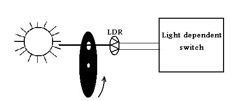
These are the parts used to make the mechanical parts of digital rpm meter.
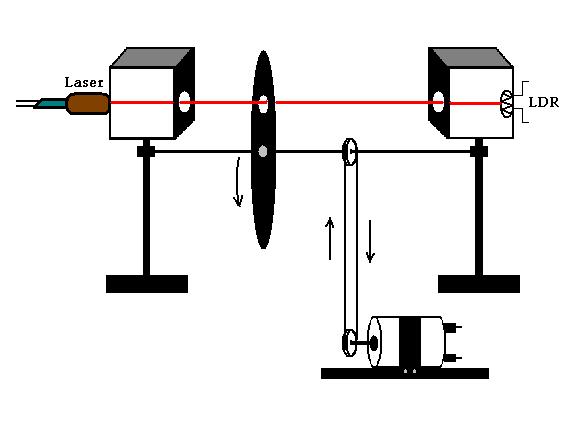
Calculator :
used the calculator for counting the pulses. Actually when any key of calculator is pressed in practical it shorts circuited two wires .Now if we press 1 on calculator and then press "+ " button then after that the equality (=) button is press again and again then increment of 1 is show on display of calculator .Now put out the two wires from the equality button and attached it to the relay which is connected to the out put of light dependent switch. When the disc rotates the light dependent switch give output pulses, which then switch ON and OFF the relay connected to the calculator.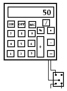
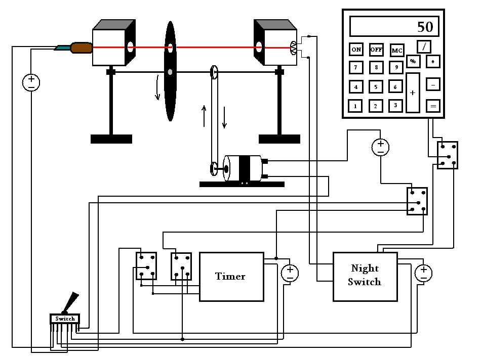
In result the display on calculator shows rot per min
X . III
SCHEMATIC DIAGRAM CALCULATOR
FIG. 17 shows the schematic diagrams of two versions of scientific calculators. The calculators are manufactured by the same manufacturer, and the new version ( FIG. 17b) is a replacement for the old version ( FIG. 17a).


FIG. 17b Schematic diagram of 45 key scientific calculator (newer version). (Texas Instruments, Inc.)
There are some very interesting differences in comparing the two versions and their associated schematics. For example, the old version has six ICs, while the new version has combined many functions and requires only two ICs. The old version has a schematic of the keyboard and a partially functioned LED display module, while the new version has a schematic symbol for both the keyboard and the LCD display module. Please note that the ICs in FIG. 17a contain an identifier beginning with Z, while the ones in FIG. 17b have an identifier beginning with U. The authors have seen several other identifiers used.
These two calculator schematics have many components and circuits identified; please compare these schematics. Overall, the schematic diagram of the new version is simpler and less cluttered than the old version
Schematics Using ICs and Other Components
Since the age of microelectronics began, there has been an evolution from drawing schematics with only discrete symbols to drawing schematics with IC symbols and discrete component symbols. As microelectronics is able to put more and more devices on an IC, it becomes totally impractical to show the schematic of an IC on an overall schematic. These schematics combining ICs and discrete symbols presume that one understands the function of the ICs used, just as one would have to know the function of a tube, for example. The following figures, together with FIG. 17, will show a few schematics containing ICs and some basic ideas on how to draw them.
FIG. 24 is a schematic of a two-phase clock for an 8080 microprocessor. This schematic uses discrete devices (resistor, capacitors, and a crystal) and ICs (NOR gates, buffers, and flip-flops). Actually, the NOR gates, the flip-flops and the buffers are each on one IC, respectively. Primarily, however, it is the timing diagram that we want to discuss when doing this type of schematic. Many digital circuit schematics utilize a timing diagram to show how the circuit works. The timing diagram can appear anywhere on the schematic, but the authors generally prefer it to be above or below its associated circuit, to make it easier to understand the circuit without having to look all over the diagram. In the circuit, the output of FF, output is half the frequency of the oscillator, 0, is the OR-inverted output of the oscillator and FF Gate 4 output 0, is buffered to TTL levels (5 V). 02 is the OR-inverted output of FF.
FIG. 25 is an 8-bit analog-to-digital converter. This circuit utilizes two AND gates with inverted outputs, an inverter, four ICs, and several discrete components. The overall schematic uses the dot system for connections. The IC pins are shown within the IC symbol. If the pin functions are to be shown, they should be shown inside the IC symbol and the pin numbers outside. Manufacturers’ model numbers are shown within the IC symbol, where it is preferred because there is less cluttering of the schematics. The voltage sources are not shown, which is generally typical for most schematics. The schematic flows from left to right with the analog input on the left and the digital output on the right. This circuit was used for teaching reasons and today it can be purchased on a single IC.
1. There are connections at points 9, 10, and 11.

FIG. 23 Preamplifier circuit of Apollo television camera. (Westinghouse Electric Corp.)

FIG. 24 Schematic diagram of a two-phase clock for an 8080 microprocessor. (EDN Magazine, January 5, 1977, p. 50.)

FIG. 25 Schematic diagram of an analog-to-digital converter (EDN Magazine, June 20, 1975, pp. 118—120).

FIG. 26 Partial schematic diagram of a two-phase clock. (EDN Magazine, September 20, 1975, pp. 53—55.)
FIG. 26 is a partial schematic of a two-phase clock for an 8080 micro processor. This schematic is an example of how the functions are shown within the symbol of the ICs (J-K flip-flops) and the labeling of the pin numbers outside the IC symbol. The IC manufacturer’s model number is shown outside the IC symbol. The schematic flows from left to right with oscillator on the left and the clock outputs on the right.
16. Hybrid Diagrams
Hybrid diagrams are just that; they can contain schematic diagrams, logic diagrams, wiring diagrams, pictorial drawings, mechanical connections, and pneumatic connections.
FIG. 27 is a hybrid diagram combining most of the aspects of a hybrid drawing, including a schematic, wiring information, logic circuitry, and mechanical devices and their associated interconnections to electrical devices. Approximately the left third of this diagram contains a schematic. The upper center portion contains a pictorial view of a gyroscope and its mechanical connection to the various synchronous . The diagram also contains logic gates (e.g., flag logic) and a schematic of the flag logic circuit. Along the right side of the diagram, there is wiring information showing the wire numbers connecting the jack pins. The reader will notice a loop-like symbol of lines 49 through 51. This indicates that the three wires are twisted together. Somewhat below this is a similar symbol which indicates that wires 45 and 46 are twisted together and shielded.
The schematic shows by means of graphic symbols the functions and connections of a specific circuit arrangement. Symbols for use in such a diagram are extensively covered in ANSI/IEEE Y32E and IEC Publication 117, and the preparation of the diagram itself is covered by ANS Y14. 15. There are certain basic arrangements of transistors and tubes which are usually repeated in electronics circuit diagrams. With these and some types of inter stage coupling, certain patterns are often discernible—usually early in the game, when one starts to plan an elementary diagram. Designation, or referencing of each component part of a circuit, is important. Certain standard abbreviations and prefixes are used for this purpose. Sufficient space must be made available near each component for referencing.

FIG. 27 Part of a system schematic of an aircraft altitude system. This is a hybrid drawing. (Douglas Aircraft Co.)
Conventional treatment is sometimes employed to eliminate the drawing of certain lines in order to avoid cluttering in a drawing. On the other hand, additional material, such as general notes and data on waveforms, is often added to a schematic diagram. A symbol is generally spaced midway along the span of circuit path on which it is drawn. Mechanical connections must be shown at times. Certain patterns are usually followed in laying out certain types of circuits in diagrammatic form. Radio circuits, for example, usually follow a cascade arrangement in which the signal path goes from left to right and the transistors are aligned horizontally. Auxiliary circuits, such as power circuits, are generally placed in the lower part of any schematic diagram. In circuits with ICs, the signal flow is generally left to right. However, due to multiple sections or functions on a single IC and several I qs within a circuit, there may be some “doubling back” to connect to a function/of a previous IC. Overall balance and symmetry are other concepts that are observed in diagrammatic layout.
Draw the schematic diagram of the all-channel CB monitor-receiver shown in FIG. 28. Use standard identification for each component. We have shown capacitor C (10 pF) at the upper left. Each capacitor and resistor should have a similar reference designation.


FIG. 28 ( Prob. 1.) Schematic diagram of CB monitor receiver. (Kantronics, Inc.)
Make any changes or improvements in the symbols or designations and values of components that you think would be appropriate. Add a suitable title and the following note: Unless otherwise specified all resistors are ± 5%, W. There is no connection at pin no.6 of the amplifier LM 380. If well planned, this diagram, with a suitable title, will fit on an 8- X 11 sheet.
2. Draw the schematic diagram of a digital clock that is shown in FIG. 29. This will fit on an 11 X 17 sheet. Complete the drawing by showing resistors R through R and drawing the CRB 1 full-wave bridge where indicated. Use ANSI practice in identifying the following components:
The corner pins are numbered on the Mostek clock chip. There are no connections to pins 13 through 17. The coil symbol at the left is part of trans former T which has an iron core. The leads from the left winding of the transformer go to the 115-v ac supply.
3. Complete the schematic diagram in FIG. 30 by insertion of the correct symbols as indicated by standard notation. Add the identification of each component and the capacity if given below. Squares Z Z etc., are integrated circuits drawn as squares or rectangles with identification shown within the square. Video input is at 12. The letter U may be substituted for Z.
This drawing will be slightly crowded on 8.5 X 11 paper and will have more than enough room on 11 X 17 paper.

FIG. 29 ( Prob. 2.) Schematic diagram of a digital clock.
4. Complete the schematic diagram of the four-function calculator shown in FIG. 31. Major elements are the terminal (at top) that connects to the LED strip (not shown), the calculator chip TMC 972, and the keyboard module. The unfinished leads should be completed by drawing lines horizontally and/or vertically to the connector indicated. Use 11 X 17 paper. Use the standard battery symbol. Show stub lines at NCs (no connections).
5. Referring to FIG. 32, fill in the IC symbol with four 2-input, distinct- shape NAND gate symbols plus zero voltage and the positive voltage:
| Pins 1 & 2 Pin 3 Pins 4 & 5 Pin 6 Pin 7 Pin 8 Pin 9 & 10 Pin 11 Pin 12 & 13 Pin 14 | Inputs to NAND gate 1 Output of NAND gate 1 Inputs to NAND gate 2 Output of NAND gate 2 Zero voltage reference Output of NAND gate 3 Inputs to NAND gate 3 Output of NAND gate 4 Inputs to NAND gate 4 Positive voltage reference (+ 5 V) |

FIG. 30 ( Prob. 3.) Post-amplifier of a moon-walk television camera.

FIG. 31 ( Prob. 4.) Schematic diagram of a four-function calculator. (Texas Instruments, Inc.)

FIG. 32 ( Prob. 5.) A four 2-input NAND-gate IC.
7. Redraw the schematic diagram shown in FIG. 33 to approximately twice the size it is shown in the guide. Use standard identification for resistors, capacitors, etc. Add the following information on or near ICs 1 and 2: Pin 1, Trigger; 2, REF; 3, R/C; 4, GND; 5, Y±; 6, C; 7, E; 8, LOGIC. On IC 3: Pin 1, CL; 2, D; 3, CLOCK; 4, GR; 5, Q; 6, Q. Use 8 X 11 paper.

FIG. 33 ( Prob. 7.) Schematic diagram of a power on reset circuit.

FIG. 34 ( Prob. 8.) An isolation circuit with optical couplers.

FIG. 35 ( Prob. 9.) Schematic diagram of a transistor clock radio.

FIG. 36 ( Prob. 10.) An unorganized schematic diagram of a VTR clock.
8. FIG. 34 is a freehand sketch of an isolation circuit that is not complete. Make an instrument drawing of this circuit that is complete, uses correct symbols in accordance with ANSI/IEEE Y32E, and has maximum identification of components. In the circuit, Q and Q are optical couplers, FCD 810 or equivalent, A and A are operational amplifiers (A is separated into two parts, A, and A2B), RB is a bias resistor, and R is a zero-adjust potentiometer. (R and R are 100 k each.) Make any corrections which appear to be appropriate. Use a standard termination scheme for EJN and E This problem will fit on 8.5 X 11 paper; 11 X 17 paper would also be OK.
9. Make a drawing of the clock-radio circuit shown in FIG. 3 5. Correct the symbols where obsolete or incorrect ones appear. Add identification for semiconductors as follows: Q converter, 95101; Q first IF, 95103; Q second IF, 95102; CR detector, IN295; Q audio driver, 95201; Q and Q audio outputs, 95220; CR rectifier, 1N290. All resistors are - W. The no-dot system has been used except at connections J and J Resistance values are in ohms unless otherwise noted, and all capacitance values are in microfarads. Use 11 X 17 or 12 X 18 paper.
10. Rearrange the unorganized schematic of a video-tape-recording (VTR) clock ( FIG. 3 6) so that it is in a logical systematic order with the input on the left and the output on the right.

FIG. 37 ( Prob. 11.) Incomplete sketch of a six-transistor AM receiver.
11. FIG. 37 is a sketch of a six-transistor radio-receiver Circuit. Many symbols are missing, but clues to their identity are given as reference designations or values. All transistors are PNP; their collector and emitter leads are identified. Capacitors at A and A are variable; no values are available. Capacitors in 455 kHz (KC is an older term) packages also have no values. Other capacitances are given as microfarads (uF) unless otherwise shown. Resistance values not already shown are as follows:
Some symbols are incorrectly shown. Reference designations may not be in the best sequence. Correct and complete the schematic diagram of this circuit, using the standard symbols and reference-designation procedure. Use 12 X 18 paper or larger.
12. FIG. 38 is the incomplete schematic diagram of a circuit that indicates at a remote location what the status of a telephone line is. LED T 1 L209 is dark when the line is not in use, on when the line is in use, and flashes when the phone is ringing. Complete the schematic by showing standard symbols for discrete elements and distinctive shapes for the logic elements. Elements should be properly identified. MCT-2 is an optical coupler. This is a tight fit on 8.5 X 11 paper.
13. FIG. 39 is a sketch of the logic diagram and schematic diagram of a flip-flop circuit. Make a complete instrument drawing of this sketch, improving symbology or layout wherever you think it is advisable. Add the following information: total capacitance, 115 pF; total resistance, 70 k tunnels (cross over paths), 14; V pin no. 3; Gnd, pin no. 8. Use 11 X 17 or 12 X 18 paper.

FIG. 38 ( Prob. 12.) A logic diagram and schematic diagram of an integrated semiconductor flip-flop circuit. (Circuit from Texas Instruments, Inc.)

FIG. 39 ( Prob. 13.) A block diagram and a schematic diagram of an IC flip-flop circuit. (Texas Instruments, Inc.)
14. FIG. 40 shows an incomplete sketch of a satellite beacon oscillator. Many symbols are missing or incorrect, but clues are present as to their correct identities and values. All transistors are PNP; their emitter and collector leads are identified. Capacitors are identified as C C or with symbols, some obsolete or nonstandard. Complete the schematic diagram insofar as possible using standard symbols and reference designations.
Some values are … Use 11 X 17 or 12 X 18 paper.

FIG. 40 ( Prob. 14.) Schematic diagram of an oscillator for a communications satellite. (Rough sketch.)

FIG. 41 ( Prob. 15.) Integrated-circuit comparator used as a clipper: (a) pictorial diagram; (b) partial schematic diagram.

FIG. 42 (Prob. 16.) Schematic diagram of a pulse generator. (EON Magazine, August 20, 1974, p. 92.)
15. FIG. 41 has a pictorial view of an IC comparator circuit used as a clipper in a. An improvement to that circuit including a Schottky diode is shown in b. Make a complete schematic diagram of the improved circuit, including waveforms. Use 8 X 11 paper.
16. FIG. 42 is a schematic of a programmable pulse generator; however, bits 4 through 10 are missing. Complete the schematic on 11 X 17 paper, adding the missing bits and the values of all the timing resistors.

FIG The first of a series of drawings for the manufacture of an integrated circuit. Greatly enlarged. (Texas Instruments, Inc.)
Whether you are a science fiction fan, a space enthusiast or one of the millions who have watched astronauts gamboling about the moon’s surface, you may have wondered how much you would weigh on other planets in the solar system. The weight depends on the gravitational forces acting on the object, which vary from planet to planet. The Newton’s law of universal gravitation says that everything that has mass attracts every other thing that has mass, pulling with a force which is directly proportional to the product of the two masses of the objects and inversely proportional to the square of the distance separating their centres. The mass and radius of different celestial bodies is mentioned in Table I.
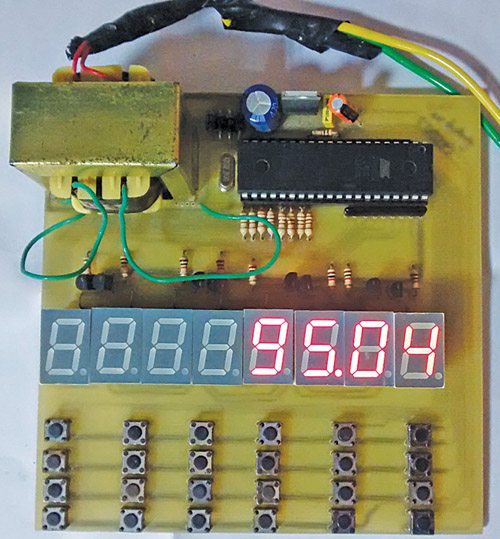
The designed embedded system takes a weight on earth and shows the weights on other celestial bodies of our solar system. The device is designed and constructed using microcontroller AT89S52. It can give better understanding about gravity. The system calculates the mass and acceleration due to gravity (g) for other celestial bodies and displays the corresponding weight (force). Fig. 1 shows the author’s prototype.
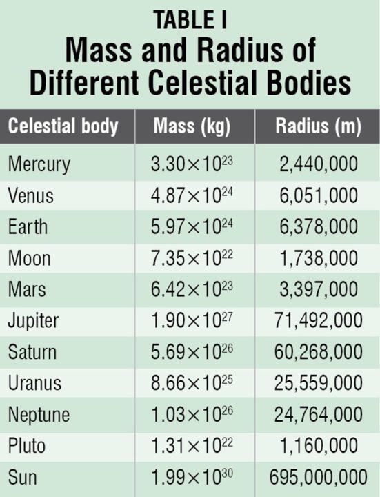
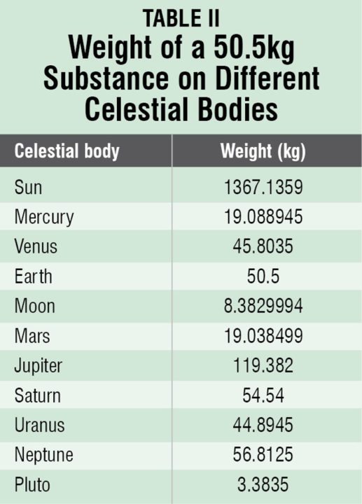
Suppose your weight on earth is 50.5 kg, your weight on other celestial bodies of our solar system would be as given in Table II.
Circuit and working
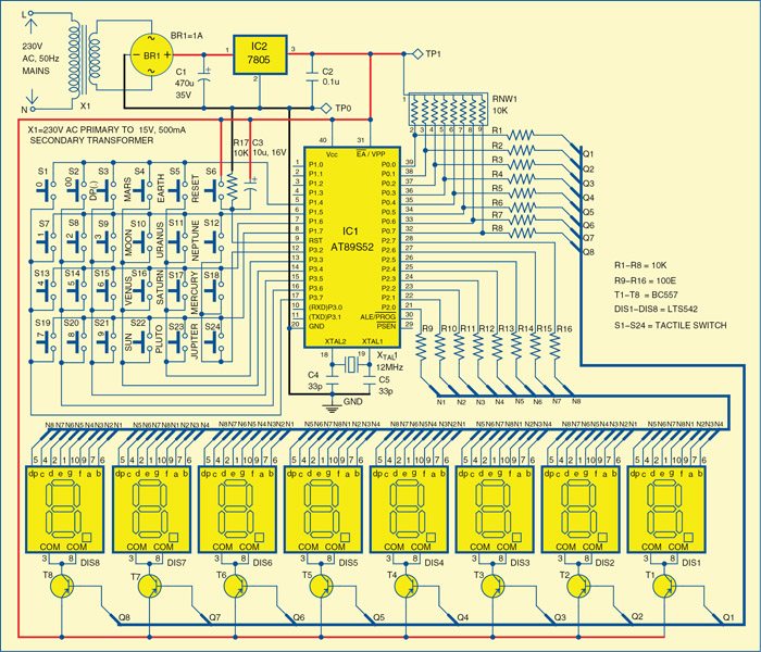
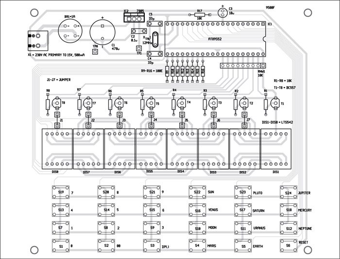
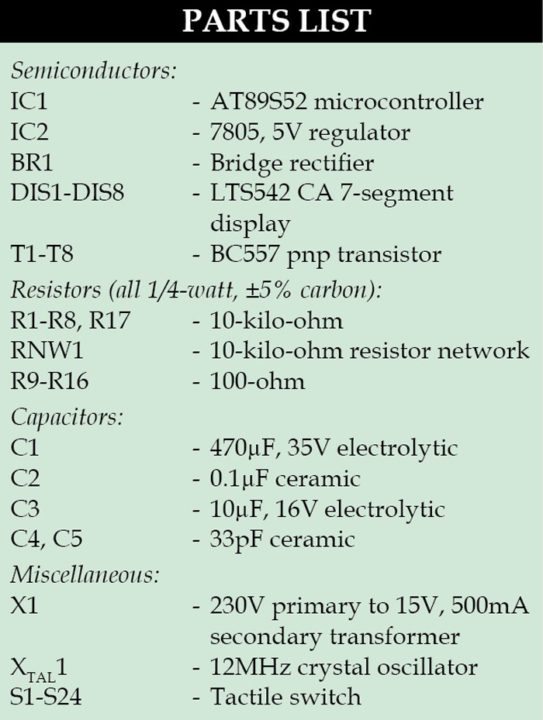 Fig. 2 shows circuit diagram of the celestial weight calculator. The circuit is built around microcontroller AT89S52 (IC1), 7-segment displays LTS542 (DIS1 through DIS8), and a few transistors and switches.
Microcontroller. AT89S52 is a low-power, high-performance CMOS 8-bit microcontroller. It provides 8k bytes of Flash, 256 bytes of RAM, 32 I/O lines, three 16-bit timer/counters, a six-vector two-level interrupt architecture, a full-duplex serial port, on-chip oscillator and clock circuitry. Power-on reset is provided by the combination of resistor R17 and capacitor C3. Switch S6 is used for manual reset. A 12MHz crystal along with two 33pF capacitors provides basic clock frequency to the microcontroller.
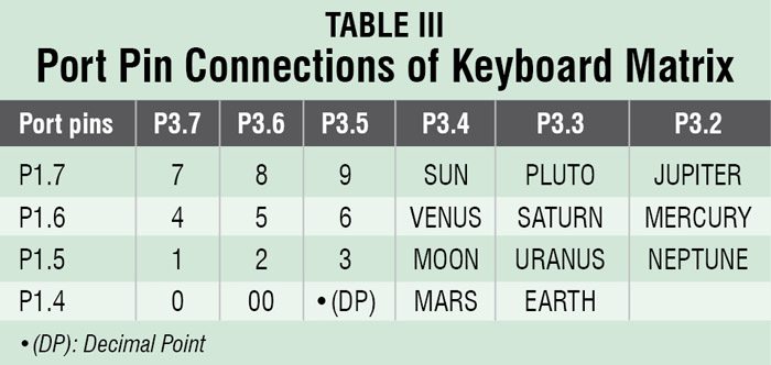
Port 0 and port 2 of IC1 are used for multiplexing the 7-segment displays (DIS1 through DIS8). The port 1 and port 3 are used for scanning the keyboard buttons, except switch S6. Transistors (T1 through T8) and resistors (R1 through R8) are used for digit selection. The 7-segment displays used are LTS542, which are common-anode type. Eight current-limiting resistors (R9 to R16) of 100Ω each are used.
The pin connections between the matrix keyboard and IC1, with key functions, are shown in Table III.
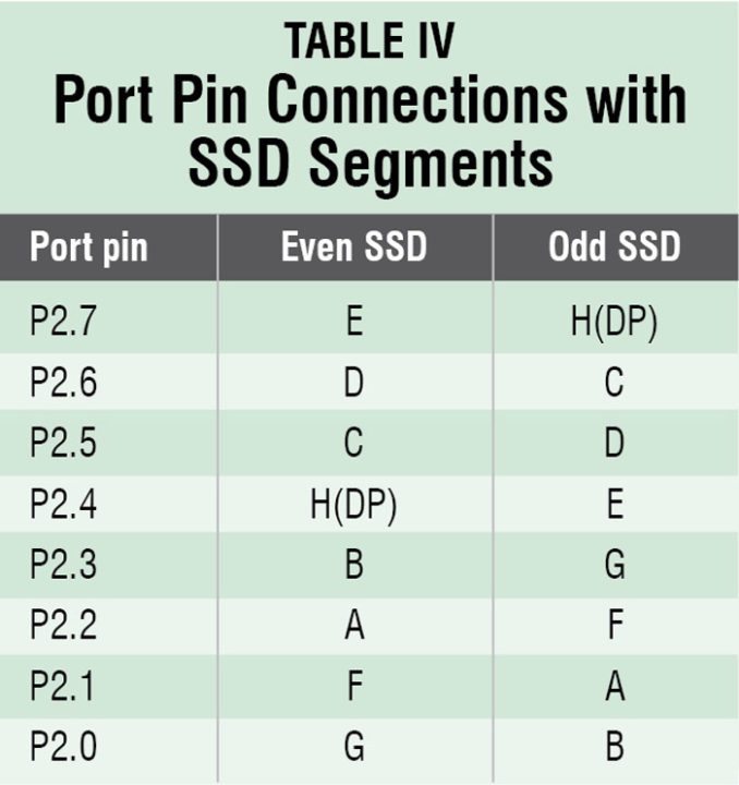
The multiplexing of eight 7-segment displays is done by using unconventional queer multiplexing technique. The even and odd segments are connected differently in this technique to make the PCB design simpler, as shown in Table IV.
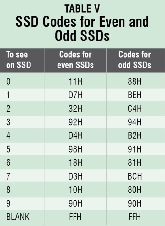
The codes to display different numbers on even and odd 7-segment displays are shown in Table V.
 The working of this device is very simple. Switch on the power supply and the device will display ‘0.’ Enter your weight on earth (either integer or real number). After entering weight press key for any celestial body and see the weight at that celestial body. To enter a new weight on earth, press Reset key.
Software
The source program for the microcontroller is written in C language and compiled using Keil µVision4 compiler. The generated hex code is burnt into the microcontroller using a suitable programmer. On reset/power-on, the microcontroller executes the main function.
The source program for the microcontroller is written in C language and compiled using Keil µVision4 compiler. The generated hex code is burnt into the microcontroller using a suitable programmer. On reset/power-on, the microcontroller executes the main function.
Construction and testing
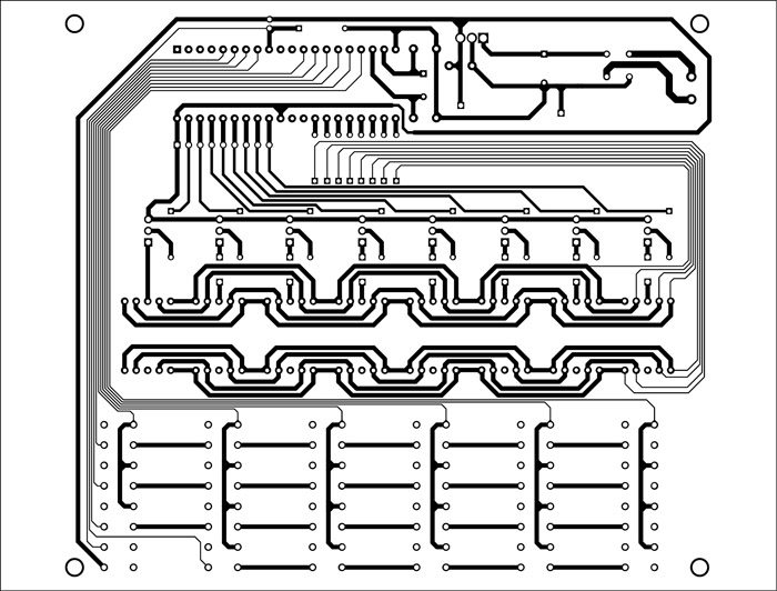
An actual-size, single-side PCB for the celestial weigh calculator is shown in Fig. 3 and its component layout in Fig. 4. Assemble the circuit on PCB to save time and minimize assembly errors. Carefully assemble the components and double-check for any overlooked error.
An actual-size, single-side PCB for the celestial weigh calculator is shown in Fig. 3 and its component layout in Fig. 4. Assemble the circuit on PCB to save time and minimize assembly errors. Carefully assemble the components and double-check for any overlooked error.
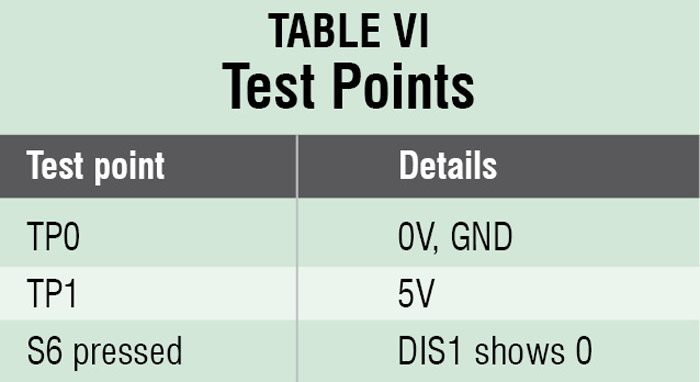
To test the circuit for proper functioning, verify correct 5V supply for the circuit at TP1 with respect to TP0.
 compare
figure abacus compare calculator telephone
X . IIII
Calculators
What is a calculator?
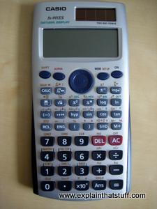
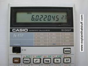
Photo: Right: My newer Casio Calculator, an fx-991ES, has a much larger "natural display" that can show entire equations and even perform calculus! The larger dark gray keys at the bottom are the numbers and the main "operators" (+, −, ×, ÷, = etc). The lighter gray keys above them carry out a whole range of scientific calculations with a single button click. The brown-colored square in the extreme top right is a solar cell that powers the machine along with a small button battery.
Our brains are amazingly versatile, but we find it hard to calculate in our heads because they can store only so many numbers. According to a famous bit of 1950s research by psychologist George Miller, we can remember typically 5–9 digits (or, as Miller put it: "the magical number seven, plus or minus two") before our brains start to ache and forget. That's why people have been using aids to help them calculate since ancient times. Indeed, the word calculator comes from the Latin calculare, which means to count up using stones.
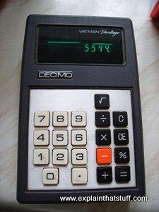
Photo: This is what calculators looked like in the 1970s. Note the very basic 8-digit green display (it's called a vacuum fluorescent display) and the relatively small number of mathematical functions (all you could really do was +, −, ×, ÷, square roots, and percentages). What you can't see from this photo is how thick and chunky this calculator was and how big its batteries were. Modern calculators are far more advanced, much cheaper, and use a fraction as much battery power.
Mechanical calculators (ones made from gears and levers) were in widespread use from the late-19th to the late-20th century. That's when the first affordable, pocket, electronic calculators started to appear, thanks to the development of silicon microchips in the late 1960s and early 1970s. Calculators have much in common with computers: they share much of the same history and work in a similar way, but there's one crucial difference: a calculator is an entirely human-operated machine for processing math, whereas a computer can be programmed to operate itself and do a whole range of more general-purpose jobs. In short, a computer is programmable and a calculator is not. (A programmable calculator sits somewhere between the two: you can program it, but only to do relatively simple mathematical calculations.)
What's inside a calculator?
If you'd taken apart a 19th-century calculator, you'd have found hundreds of parts inside: lots of precision gears, axles, rods, and levers, greased to high heaven, and clicking and whirring away every time you keyed in a number. But take apart a modern electronic calculator (I just can't resist undoing a screw when I see one!) and you might be disappointed at how little you find. I don't recommend you do this with your brand-new school calculator if you want to stay on speaking terms with your parents, so I've saved you the bother. Here's what you'll find inside: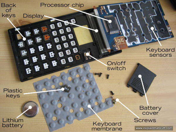
Caption: Inside the fx-570, which is face-down here. We're effectively looking up into the machine from below.
Don't worry, I managed to put it all back together again just fine!
- Input: Keyboard: About 40 tiny plastic keys with a rubber membrane underneath and a touch-sensitive circuit underneath that.
- Processor: A microchip that does all the hard work. This does the same job as all the hundreds of gears in an early calculator.
- Output: A liquid crystal display (LCD) for showing you the numbers you type in and the results of your calculations.
- Power source: A long-life battery (mine has a thin lithium "button" cell that lasts several years). Some calculators also have a solar cell to provide free power in the daylight.
What happens when you press a key?
Press down on one of the number keys on your calculator and a series of things will happen in quick succession:- As you press on the hard plastic, you compress the rubber membrane underneath it. This is a kind of a miniature trampoline that has a small rubber button positioned directly underneath each key and a hollow space underneath that. When you press a key, you squash flat the rubber button on the membrane directly underneath it.

Photo: The keyboard membrane. I've left one of the keys on the membrane to give you an idea of the scale. There's one rubber button directly beneath each key. - The rubber button pushes down making an electrical contact between two layers in the keyboard sensor underneath and the keyboard circuit detects this.
- The processor chip figures out which key you have pressed.
- A circuit in the processor chip activates the appropriate segments on the display corresponding to the number you've pressed.
- If you press more numbers, the processor chip will show them up on the display as well—and it will keep doing this until you press one of the operations keys (such as +, −, ×, ÷) to make it do something different. Suppose you press the + key. The calculator will store the number you just entered in a small memory called a register. Then it will wipe the display and wait for you to enter another number. As you enter this second number, the processor chip will display it digit-by-digit as before and store it in another register. Finally, when you hit the = key, the calculator will add the contents of the two registers together and display the result. There's a little more to it than that—and I'll go into a few more details down below.
Artwork: A seven-segment display can show all the numbers from 0-9.
How does the display work?
You're probably used to the idea that your computer screen makes letters and numbers using a tiny grid of dots called pixels. Early computers used just a few pixels and looked very dotty and grainy, but a modern LCD screen uses millions of pixels and is almost as clear and sharp as a printed book. Calculators, however, remain stuck in the dark ages—or the early 1970s, to be precise. Look closely at the digits on a calculator and you'll see each one is made from a different pattern of seven bars or segments. The processor chip knows it can display any of the numbers 0-9 by activating a different combination of these seven segments. It can't easily display letters, though some scientific calculators (more advanced electronic calculators with lots of built into mathematical and scientific formulae) do have a go.How does a calculator add two numbers together?
So far we've had a very simple look at what's going on inside a calculator, but we've not actually got to the heart of how it takes two numbers and adds them to make a third one. For those of you who'd like a bit more detail, here's a slightly more technical explanation of how that happens. In short, it involves representing the decimal numbers we use in a different format called binary and comparing them with electrical circuits known as logic gates.Representing numbers in binary
Humans work on numbers in decimal format (the numbers 0–9) largely, it's believed, because we have ten fingers and toes to count with. But the numbers we use to write out amounts of things are arbitrary. Let's say you have a pile of coins and you want to tell me how wealthy you are. You can point to the pile, I can look at it, and if I see a lot of coins I'll conclude you're rich. But what if I'm not there to look at the pile? Then you can use a symbol to represent the coins—and that's what a number is: a symbol that indicates an amount. If there were nineteen coins, you could use the two symbols "1" and "9" written together: 19. Taken together, that means 1 × 10 plus 9 × 1 = 19. That's how decimal works using a system of 10 symbols. But you could use other symbols too.For the last century or so, computers and calculators have been built from a variety of switching devices that can either be in one position or another. Just like a light-switch, they're either "on" or "off." For that reason, computers and calculators store and process numbers using what's called binary code, which uses just two symbols (0 and 1) to represent any number. So in binary code, the number 19 is written 10011, which means (1 × 16) + (0 × 8) + (0 × 4) + (1 × 2) + (1 × 1) = 19. The beauty of binary is that you can represent any decimal number with a series of switches that are either on or off—perfect for a calculator or a computer—like this:

Using logic gates with binary
Let's say you want to do the sum 3 + 2 = 5.A calculator tackles a problem like this by turning the two numbers into binary, giving 11 (which is 3 in binary = 1 × 2 + 1 × 1) plus 10 (2 in binary = 1 × 2 + 0 × 1) makes 101 (5 in binary = 1 × 4 + 0 × 2 + 1 × 1). How does the calculator do the actual sum? It uses logic gates to compare the pattern of switches that are active and come up with a new pattern of switches instead.
A logic gate is really just a simple electrical circuit that compares two numbers (inputs) and produces a third number (an output) depending on the values of the original numbers. There are three very common types of logic gates called OR, AND, and NOT (and a few others too, which we won't go into here). An OR gate has two inputs (each of which can be either 0 or 1) and it produces an output of 1 if either of the inputs is 1; it produces a zero otherwise. An AND gate also has two inputs, but it produces an output of 1 only if both inputs are 1. Finally, a NOT gate has a single input and reverses it to make an output. So if you feed it a zero, it produces a 1 (and vice-versa).
Now if you put lots of logic gates together, you can make more complex circuits called adders. You feed into these circuits two binary numbers as their input and get out a third, binary number as your output. The number that comes out is the binary sum of the numbers you put in. So if you fed in the electrical signals 10 and 11 you would get out 101 (2 + 3 = 5). How does an adder work? That's beyond the scope of this introductory article, but you can find a few examples on the web pages below.
Unless you're doing a degree in electronics or computing, all you really need to know is that an adder is built from a number of AND, OR, and NOT logic gates contained inside chips that are connected together. We can use other patterns of logic gates to subtract, multiply (which can also be done by repeated addition), and do other kinds of calculations.
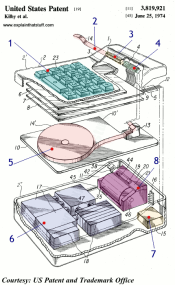
Artwork: Who invented the pocket calculator? Jack Kilby and colleagues at Texas Instruments in a patent filed in 1972 and granted two years later. Here's how it worked: (1) You typed your sums into the keyboard and watched the answer appear, shortly afterward, on a printed paper tape (there was no display) at the top (2). A magnifying lens (3) helped you decipher the tiny numbers produced by the printer (4). Inside the case, we can see the paper tape that feeds the printer (5). Beneath it, there's a huge bank of batteries (6), a relatively tiny box full of electronics (7), and the thermal printer mechanism (8). Find out more in US Patent 3,819,921: Miniature electronic calculator. Artwork courtesy of US Patent and Trademark Office (coloring and large numbers added for clarity).
LCDs (liquid crystal displays)
Televisions used to be hot, heavy, power-hungry beasts that sat in the corner of your living room. Not any more! Now they're slim enough to hang on the wall and they use a fraction as much energy as they used to. Like laptop computers, most new televisions have flat screens with LCDs (liquid-crystal displays)—the same technology we've been using for years in things like calculators, cellphones, and digital watches. What are they and how do they work? Let's take a closer look!
Photo: Small LCDs like this one have been widely used in calculators and digital watches since the 1970s, but they were relatively expensive in those days and produced only black-and-white (actually, dark-blueish and white) images. During the 1980s and 1990s, manufacturers figured out how to make larger color screens at relatively affordable prices. That was when the market for LCD TVs and color laptop computers really took off.How does a television screen make its picture?
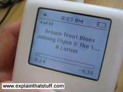
Photo: This iPod screen is another example of LCD technology. Its pixels are colored black and they're either on or off, so the display is black-and-white. In an LCD TV screen, much smaller pixels colored red, blue, or green make a brightly colored moving picture.
For many people, the most attractive thing about LCD TVs is not the way they make a picture but their flat, compact screen. Unlike an old-style TV, an LCD screen is flat enough to hang on your wall. That's because it generates its picture in an entirely different way.
You probably know that an old-style cathode-ray tube (CRT) television makes a picture using three electron guns. Think of them as three very fast, very precise paintbrushes that dance back and forth, painting a moving image on the back of the screen that you can watch when you sit in front of it.
Flatscreen LCD and plasma screens work in a completely different way. If you sit up close to a flatscreen TV, you'll notice that the picture is made from millions of tiny blocks called pixels (picture elements). Each one of these is effectively a separate red, blue, or green light that can be switched on or off very rapidly to make the moving color picture. The pixels are controlled in completely different ways in plasma and LCD screens. In a plasma screen, each pixel is a tiny fluorescent lamp switched on or off electronically. In an LCD television, the pixels are switched on or off electronically using liquid crystals to rotate polarized light. That's not as complex as it sounds! To understand what's going on, first we need to understand what liquid crystals are; then we need to look more closely at light and how it travels.
What are liquid crystals?
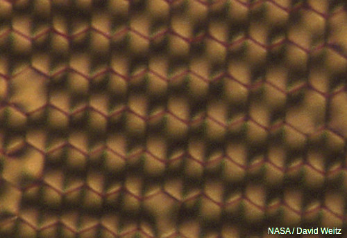
Photo: Liquid crystals dried and viewed through polarized light. You can see they have a much more regular structure than an ordinary liquid. Photo from research by David Weitz courtesy of NASA Marshall Space Flight Center (NASA-MSFC).
We're used to the idea that a given substance can be in one of three states: solid, liquid, or gas—we call them states of matter—and up until the late 19th century, scientists thought that was the end of the story. Then, in 1888, an Austrian chemist named Friedrich Reinitzer (1857–1927) discovered liquid crystals, which are another state entirely, somewhere in between liquids and solids. Liquid crystals might have lingered in obscurity but for the fact that they turned out to have some very useful properties.
Solids are frozen lumps of matter that stay put all by themselves, often with their atoms packed in a neat, regular arrangement called a crystal (or crystalline lattice). Liquids lack the order of solids and, though they stay put if you keep them in a container, they flow relatively easily when you pour them out. Now imagine a substance with some of the order of a solid and some of the fluidity of a liquid. What you have is a liquid crystal—a kind of halfway house in between. At any given moment, liquid crystals can be in one of several possible "substates" (phases) somewhere in a limbo-land between solid and liquid. The two most important liquid crystal phases are called nematic and smectic:
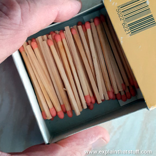
- When they're in the nematic phase, liquid crystals are a bit like a liquid: their molecules can move around and shuffle past one another, but they all point in broadly the same direction. They're a bit like matches in a matchbox: you can shake them and move them about but they all keep pointing the same way.
- If you cool liquid crystals, they shift over to the smectic phase. Now the molecules form into layers that can slide past one another relatively easily. The molecules in a given layer can move about within it, but they can't and don't move into the other layers (a bit like people working for different companies on particular floors of an office block). There are actually several different smectic "subphases," but we won't go into them in any more detail here.
What is polarized light?
Nematic liquid crystals have a really neat party trick. They can adopt a twisted-up structure and, when you apply electricity to them, they straighten out again. That may not sound much of a trick, but it's the key to how LCD displays turn pixels on and off. To understand how liquid crystals can control pixels, we need to know about polarized light.Light is a mysterious thing. Sometimes it behaves like a stream of particles—like a constant barrage of microscopic cannonballs carrying energy we can see, through the air, at extremely high speed. Other times, light behaves more like waves on the sea. Instead of water moving up and down, light is a wave pattern of electrical and magnetic energy vibrating through space.

Photo: A trick of the polarized light: rotate one pair of polarizing sunglasses past another and you can block out virtually all the light that normally passes through.

Photo: A less well known trick of polarized light: it makes crystals gleam with amazing spectral colors due to a phenomenon called pleochroism. Photo of protein and virus crystals, many of which were grown in space. Credit: Dr. Alex McPherson, University of California, Irvine. Photo courtesy of NASA Marshall Space Flight Center (NASA-MSFC).
When sunlight streams down from the sky, the light waves are all mixed up and vibrating in every possible direction. But if we put a filter in the way, with a grid of lines arranged vertically like the openings in prison bars (only much closer together), we can block out all the light waves except the ones vibrating vertically (the only light waves that can get through vertical bars). Since we block off much of the original sunlight, our filter effectively dims the light. This is how polarizing sunglasses work: they cut out all but the sunlight vibrating in one direction or plane. Light filtered in this way is called polarized or plane-polarized light (because it can travel in only one plane).
If you have two pairs of polarizing sunglasses (and it won't work with ordinary sunglasses), you can do a clever trick. If you put one pair directly in front of the other, you should still be able to see through. But if you slowly rotate one pair, and keep the other pair in the same place, you will see the light coming through gradually getting darker. When the two pairs of sunglasses are at 90 degrees to each other, you won't be able to see through them at all. The first pair of sunglasses blocks off all the light waves except ones vibrating vertically. The second pair of sunglasses works in exactly the same way as the first pair. If both pairs of glasses are pointing in the same direction, that's fine—light waves vibrating vertically can still get through both. But if we turn the second pair of glasses through 90 degrees, the light waves that made it through the first pair of glasses can no longer make it through the second pair. No light at all can get through two polarizing filters that are at 90 degrees to one another.
How LCD televisions use liquid crystals and polarized light

Photo: Prove to yourself that an LCD display uses polarized light. Simply put on a pair of polarizing sunglasses and rotate your head (or the display). You'll see the display at its brightest at one angle and at its darkest at exactly 90 degrees to that angle.

Photo: How liquid crystals switch light on and off. In one orientation, polarized light cannot pass through the crystals so they appear dark (left side photo). In a different orientation, polarized light passes through okay so the crystals appear bright (right side photo). We can make the crystals change orientation—and switch their pixels on and off—simply by applying an electric field. Photo from liquid crystal research by David Weitz courtesy of NASA Marshall Space Flight Center (NASA-MSFC).
An LCD TV screen uses the sunglasses trick to switch its colored pixels on or off. At the back of the screen, there's a large bright light that shines out toward the viewer. In front of this, there are the millions of pixels, each one made up of smaller areas called sub-pixels that are colored red, blue, or green. Each pixel has a polarizing glass filter behind it and another one in front of it at 90 degrees. That means the pixel normally looks dark. In between the two polarizing filters there's a tiny twisted, nematic liquid crystal that can be switched on or off (twisted or untwisted) electronically. When it's switched off, it rotates the light passing through it through 90 degrees, effectively allowing light to flow through the two polarizing filters and making the pixel look bright. When it's switched on, it doesn't rotate the light, which is blocked by one of the polarizers, and the pixel looks dark. Each pixel is controlled by a separate transistor (a tiny electronic component) that can switch it on or off many times each second.
How colored pixels in LCD TVs work
There's a bright light at the back of your TV; there are lots of colored squares flickering on and off at the front. What goes on in between? Here's how each colored pixel is switched on or off:
How pixels are switched off
- Light travels from the back of the TV toward the front from a large bright light.
- A horizontal polarizing filter in front of the light blocks out all light waves except those vibrating horizontally.
- Only light waves vibrating horizontally can get through.
- A transistor switches off this pixel by switching on the electricity flowing through its liquid crystal. That makes the crystal straighten out (so it's completely untwisted), and the light travels straight through it unchanged.
- Light waves emerge from the liquid crystal still vibrating horizontally.
- A vertical polarizing filter in front of the liquid crystal blocks out all light waves except those vibrating vertically. The horizontally vibrating light that travelled through the liquid crystal cannot get through the vertical filter.
- No light reaches the screen at this point. In other words, this pixel is dark.
How pixels are switched on
- The bright light at the back of the screen shines as before.
- The horizontal polarizing filter in front of the light blocks out all light waves except those vibrating horizontally.
- Only light waves vibrating horizontally can get through.
- A transistor switches on this pixel by switching off the electricity flowing through its liquid crystal. That makes the crystal twist. The twisted crystal rotates light waves by 90° as they travel through it.
- Light waves that entered the liquid crystal vibrating horizontally emerge from it vibrating vertically.
- The vertical polarizing filter in front of the liquid crystal blocks out all light waves except those vibrating vertically. The vertically vibrating light that emerged from the liquid crystal can now get through the vertical filter.
- The pixel is lit up. A red, blue, or green filter gives the pixel its color.
What's the difference between LCD and plasma?
A plasma screen looks similar to an LCD, but works in a completely different way: each pixel is effectively a microscopic fluorescent lamp glowing with plasma. A plasma is a very hot form of gas in which the atoms have blown apart to make negatively charged electrons and positively charged ions (atoms minus their electrons). These move about freely, producing a fuzzy glow of light whenever they collide. Plasma screens can be made much bigger than ordinary cathode-ray tube televisions, but they are also much more expensive.Recreating the First Microprocessor-Based Calculator

In 1969, Japanese electronics manufacturer Busicom approached a little startup called Intel to develop a chipset for their new 141-PF electronic printing calculator. Intel's solution was the world's first single chip microprocessor -- the tiny Intel 4004 -- which powered the Busicom machine to groundbreaking success in 1971.
37 years later, Bill Kotaska has crafted a replica of this historical machine capable of running the software from the original Busicom ROMs. He even went to the trouble of buying an old calculator of approximately the right vintage and rearranging the mechanical switches to match the original Busicom layout.
The printer mechanism was originally manufactured by Epson, and Kotaska was able reuse one from an old Monroe 1330 printing calculator, although the lack of a full schematic diagram made it tough for Kotaska to figure out exactly how it was supposed to interface with the logic circuit. He eventually got it running and the result is a stunning bit of retroputing history.

Busicom sold 100,000 Intel-based calculators before finding themselves in financial trouble. Intel used this misstep to their advantage and bought back the rights to the chip for non-calculator applications.
The 4004 was a tiny 4-bit processor with an 8-bit wide instruction set. It was capable of running at speeds up to 740 kHz and could address up to 4K of ROM and 1280 x 4bits of RAM, although the accompanying MCS-4 chipset included a tiny 256 byte mask-programmable ROM and 340 byte RAM chip. It seems laughable by todays standards, but those meager specifications were enough to open up a brand new world of programmable logic capable of replacing extremely complicated and expensive electromechanical systems.
Intel followed the success of this little 16 pin chip with the 8008, a 3,300 transistor 8-bit chip that was introduced in late 1972. The company went on the have a string of successes throughout the 1970s, but it was the incorporation of their processors into the IBM-PC lineup in the 1980s that enabled them to become the largest processor manufacturer in the world.
Incidentally, original 4004 chips are now highly collectible and a rare gold-white-grey chip like the one shown here can change hands for well over $1000. That said, I'd much rather have been given $1000 of Intel stock in the early 1970s - it'd be worth over $500,000 today -- enough for a massive stack of vintage chips.
X . IIIII
Some important Facts We Need to Know about Satellite Internet
Like all of us, you have probably been bombarded with junk mail from satellite TV companies and dealers advertising “new” satellite Internet service. For many years, Direct Communications sold satellite Internet service as a last-resort product for customers simply too far away to receive any other kind of service. More recently, we decided to stop offering the product altogether, as fixed and mobile wireless data options and coverage increased, and customer bandwidth demand for services like streaming video made satellite a very unattractive solution for most people.
There are two fundamental problems with satellite Internet that will not go away, no matter how much the satellite TV dealers try to market their Internet product as a viable solution, tell you it’s “new and improved,” and try to get customers to bundle an inferior satellite internet with satellite TV. Don’t be fooled–satellite should only be used if there is no other possible way on earth you can get Internet service to your home–while it still has a place for homes in very remote locations (off-the-grid basically) it is a very inferior way to deliver internet service, and cannot meet the needs of most modern Internet users.
Satellites are in space.
This isn’t a problem for delivering a one-way, linear TV service, but sending Internet packets of data back and forth, thousands of miles into the sky and then back down again wirelessly, creates some serious time lag issues. Expect to wait several seconds for a response from the remote website server each time you click. This can be very tedious at the best of times even just browsing, and extremely frustrating any time you are trying to do anything interactive online like chat, game, or shop.
Data Caps
Beware–if you are used to unlimited Internet usage, switching to satellite Internet will make you very frustrated and angry.
Even on the top available satellite Internet plan, ($80 per month) you still only get 30 GB of data to use each month. This will be a serious problem for almost all normal internet users, because if you use all of that data before the month is up, you must either pay extra to buy more data or have your Internet speed significantly reduced. Some providers advertise 15 GB of “bonus data” in their plans, but NOTE: this may only be used between 2am and 8 am.
If you get near the cap, they’ll send you a warning notice. If you exceed it, they’ll throttle your speed to down 128k (dial-up). You can add additional data in 1GB increments for $10 each.
All of the satellite companies enforce data caps or throttling policies, and they will tell you up front not to stream video online. Now, consider this: Streaming in 1080p on Netflix takes up 4.7GB/hour. That means the average HD movie download uses over 10GB of data. If you watched just one movie online a night, that would use up 300GB of data a month. But, you are not just watching movies, are you? You are banking, surfing, emailing, downloading photos and videos from your family. Your kids are streaming kids shows all day long on Netflix, and probably streaming music all day long at home. If you are using Satellite Internet, you could easily burn through an entire monthly data allotment in one day. Over half of Directcom customers use about 250 GB per month of data per household, and our top 10% of streamers average over 460GB per month. We calculate that our average customer would be paying an extra $15 a month in data overages with the leading wireless ISP in the area, and over $1000 a month using 4G from the leading cell phone providers.
For example, the Dish corporate website clearly states that satellite internet is not meant to be a substitute for regular wired internet service:
“The Internet provider at my current location is cable/fiber. Is dishNET Satellite a good solution for me?
NO, As a satellite-based service, dishNET Satellite Internet has monthly Data Allowance limits which are much lower
than cable and fiber-based Internet providers. Additionally, with satellite-based systems signal latency (delay) occurs,
which may negatively affect some activities such as real-time gaming and VoIP.
I enjoy watching TV shows and movies online with my current provider. Is dishNET Satellite a good solution
for me?
NO, If your current provider supports these services, we do not recommend switching to dishNET. While dishNET
Satellite will support video streaming, it is best to limit these activities to short video clips like those found on YouTube®
or rich content sites operated by ESPN and the like. Streaming video uses a large amount of data. If you use dishNET
Satellite to stream video from services like Netflix® or Hulu® you will quickly consume your monthly Data Allowance,
resulting in your speed being reduced.”
Local satellite dealers may still try to sell you this service. Don’t be fooled, and don’t pay extra. Trust Directcom Fiber Optic Broadband for all your family’s entertainment and connectivity needs. No Caps. No Throttling. No Limits!
So, why are companies like Dish trying so hard to sell you satellite Internet service?
A lot of the junk mail is coming from local dealers wanting a sale no matter whether it’s a good fit for you. But, in the bigger picture, the writing is on the wall for traditional satellite TV service, with more and more people moving to online entertainment sources like Netflix, Hulu, Amazon, YouTube etc. With their TV subscriber base decreasing each year, satellite companies are very aggressively seeking for new sources of revenue. They know the Internet is the future of entertainment. This could be why Dish bought up several satellite Internet companies recently, and has been aggressively purchasing wireless bandwidth all over the country. Dish recently announced a streaming TV service called Sling TV, which skips satellite altogether and allows people watch all their TV purely online. We applaud these moves and hope to see more convenient online video options for consumers, but you will need an unlimited bandwidth plan to enjoy all this streaming video.
“The Internet provider at my current location is cable/fiber. Is dishNET Satellite a good solution for me?
NO, As a satellite-based service, dishNET Satellite Internet has monthly Data Allowance limits which are much lowerthan cable and fiber-based Internet providers. Additionally, with satellite-based systems signal latency (delay) occurs,
which may negatively affect some activities such as real-time gaming and VoIP.
I enjoy watching TV shows and movies online with my current provider. Is dishNET Satellite a good solution
for me?
NO, If your current provider supports these services, we do not recommend switching to dishNET. While dishNETfor me?
Satellite will support video streaming, it is best to limit these activities to short video clips like those found on YouTube®
or rich content sites operated by ESPN and the like. Streaming video uses a large amount of data. If you use dishNET
Satellite to stream video from services like Netflix® or Hulu® you will quickly consume your monthly Data Allowance,
resulting in your speed being reduced.”
Satellite Manufacturers Look to Cultural Shift to Cope with Changing Market

The Metop B satellite encapsulated in it’s payload fairing in 2012. Photo: European Space Agency.
Company executives at SATELLITE 2016’s satellite manufacturer’s forum “Instant Adaptation to an Instant Culture” emphasized the necessity of cultural change alongside technological changes in order to acclimate to a rapidly evolving market. While new entrants come onto the scene asking for new ideas and time-tested technology on a shorter timeline than ever before, CEOs of satellite manufacturers are also seeing a decline in new orders. In fact, Northern Sky Research (NSR) released numbers that reflected companies had placed just 19 orders for commercial GEO communications satellites in 2015, a steep decline from the 28 orders in 2014 and more of a decline than the industry was forecasting.

The Metop B satellite encapsulated in it’s payload fairing in 2012. Photo: European Space Agency.
NewSpace, New Culture
Manufacturers believe that by pushing a cultural shift they can cope with the changing market as NewSpace and SmallSats flip the industry on its head. These shifts can also help introduce new, affordable tech, such as flexible payloads that can dynamically reallocate capacity in response to changes in demand.
“Some of today’s innovations really come down to culture, what’s in your blood, and how you live and breathe that,” said Mark Spiwak, president of Boeing Satellite Systems International, pointing to new technology such as satellites that have the digital capability to move bandwidth to meet customers’ demands. “As an industry, this is a very exciting time. We are changing, our products are changing, our services are changing, and the expectations of customers are changing. This innovation and instant adaptation is being prepared to meet the demands of the marketplace.”
Paul Etsey, vice president of engineering, manufacturing and test operations at Space Systems Loral (SSL), which is located in the heart of Silicon Valley, Calif., believes that the NewSpace companies are entrenched in a Silicon Valley culture that is based around constant change. SSL has embarked on an initiative to model itself around the speed and innovation present in the culture of Silicon Valley that he feels has not existed in the space industry for many years.
“NewSpace came along and really challenged how we do things,” said Etsey, pointing to culture as the main barrier to pushing new technologies and ideas forward. “We had to change not only what our products were, but how we did things. And what we found over the past couple of years is that it is all about culture — the culture inside our company, the culture of our customers, the culture of our suppliers. In order to change culture, it takes an extreme amount of commitment from the CEO all the way down to the technician on the floor.”
To implement change the company looked to learn from how SmallSat startups are using pre-existing tech as well as bring in younger employees to revamp the “stodgy” space arena.
New Tech
Manufacturers are hoping this change in culture will help push more innovations like the adoption of electric propulsion, which panelists agreed would be built into an estimated 75 percent of spacecraft by 2020. Large satellite manufactures can also look to learn from the technology and procurement methods used in SmallSats that NewSpace companies are producing.
“[With OneWeb] we are going to produce between three and four satellites a day. The cycle is very different. Here, there is the matter of the supply chain having the capability in the suppliers to produce the supplies, but there is also the matter of organizing the supply chain. Also, of course, this means the procurement processes and pushing some innovation in the industry of processes. We are learning this in what we are building now … this can help us to foster ideas on how to do things differently with larger satellites in the design side and the testing side,” said Eric Beranger, managing director of space systems programs at Airbus Defense and Space.
Companies are also hoping to inject more standardization in coming spacecraft.
“At Lockheed Martin we are looking to standardize the product line,” said Carl Marchetto, vice president and general manager of Lockheed Martin Space Systems. As the company looked to modernize its A2100 platform it found the offerings were quite diverse and looked to implement a scalable product line.
“Alongside driving down our cycle costs, the uniformity pays off across the entire enterprise and with our supply chain,” said Marchetto, noting that the company is not ready to standardize everything and will hang on to some areas of testing.
Beranger also noted that further standardization could be pushed by the advent of on-orbit reconfigurable satellites.
“It may not be too far away that a satellite with a totally fixed mission will look a little bit outdated,” said Beranger. “If this time arrives then it will allow us to be even more standardized because then you have the same product but you simply program it to a particular mission.”
New Ways Forward
“In terms of culture and community we have seen a community of passion … but these technologies are not only coming from us, our customers or our industry. What is happening is that space is getting more and more popular. It is more used by more people from outside communities,” said Beranger. “Today there are billions of people using satellites and this enlargement of the community accessing usage is driving the explosion of the needs and innovation.”
Beranger believes that 5G, or the capability of delivering connectivity to “anything, anytime, anywhere,” is one of these technologies that end users are progressing toward, which the satellite industry will have to work to accommodate, but that there will be all types of new tech coming to the forefront as customers demand new capabilities and faster times to orbit.
Space Business Leaders Look to the Future of the Satellite Market
“We have to adapt to change,” said Clayton Mowry, president of Arianespace. “When we started in this business we were competing against the space shuttle and then we evolved to compete against Atlas, Delta, Proton, Zenit, Falcon, all these new systems that have come on the market place … It’s not the strongest or the most intelligent that survive but those that are most able to adapt for change that are most able to survive and thrive in the world,” Mowry added, quoting Charles Darwin.
The Need for Speed
Companies are already operating in a shifting marketplace, as NewSpace companies out of Silicon Valley are shaking up the market across the value chain by introducing new launch systems to compete with traditional space companies.
“In this emerging market we have to be very much market driven and part of that is that we have to be driven by speed to market to keep up with the emerging market,” said Jay Gibson, CEO and president of XCOR, a new business developing a spacecraft that will enable suborbital and then orbital business services.
Gibson sees platform reusability and flexibility driving this change and opening the door to faster speed to market. He expects adaptable platforms will, in turn, drive the business case for companies looking to find their way in the NewSpace landscape.
“When you get to reusability, you start to achieve what then brings us into a commercial environment, which is frequency and affordability. And when you do that you open up the market to all kinds of interesting things. You allow the market to drive who you are and what you do,” Gibson said.
Speed to market is impacting established launch companies as well, as they look to accommodate more rapid mission needs from startups and small satellite companies. This includes attempting to accommodate companies such as OneWeb, which is looking to launch 21 satellites in 18 months, according to Mowry.
“For the NewSpace companies [the business case for return on investment] is definitely on a shorter time line. If you’re talking about these guys who are able to produce those satellites rather quickly — not in a two to three year timeline to build a geostationary platform, but in 18 months, a year, or even less with CubeSats — these guys are looking at launch opportunities with my company much more quickly than we would typically … these guys are looking at much more compressed timelines and it’s something we need to adapt to,” said Mowry.
Accessing Affordability
To make the business case, space companies are also searching for ways to drive down the price point and introduce more affordable services, satellites and launches. Bandwidth providers are looking to up the capacity of a given satellite through High Throughput Satellite (HTS) systems and other advances to accommodate this change.
“It’s not just in the launch business where we need to be affordable, we need to be affordable on the platform side,” said Kay Sears, president of Intelsat General. “Affordability will drive new applications, especially applications like the Internet of Things (IoT), so the constellation that we are building right now that will launch over the next couple of years will target mobility and these new kinds of Internet of Things applications.”
The company’s EpicNG platform, launching in January, will have about 10 times the total throughput of its current satellites through the creation of a multi-spot pattern across the coverage. Instead of a widebeam satellite there are several smaller spot beams, which increase the downlink power to enable the use of smaller antennas. They also allow the company to reuse the spectrum so the total throughput of the satellite increases and the cost-per-bit goes down, according to Sears.
New manufacturing protocols may also open the door to more affordable systems, according to Eric Thoemmes, vice president of space and missile defense programs at Lockheed Martin.
“In the manufacturing world there is a dramatic revolution going on as to how we approach the design, development and production of space vehicles,” said Thoemmes who spoke to a concept in which the company uses digital design capabilities to curb issues that pop up as spacecraft move from concept to build.
“The digital tapestry is all about taking 3-D design capabilities, taking those all the way through engineering and directly into manufacturing. In the past we would have design; and those people would do drawings; and those would be passed on to manufacturing; and those in manufacturing would try to decide how to implement that; and, in many cases, spend a lot of time correcting problems that were not envisioned in the design phase. With digital design, you are able to walk yourself through the entire value chain all the way through the production and into operations, to some extent, of these satellites,” Thoemmes said.
Additive manufacturing, or 3-D printing, is also helping the company to bring componentry into the space domain that it could not have designed in the past. Lockheed Martin is using these ideas to modernize its A2100 spacecraft in the government domain as well as in the commercial market. A recent contract win, the Hellas-Sat 4/SaudiGeoSat 1, which will carry a flexible payload, will showcase these improvements. Thoemmes also pointed to a recent unselected proposal Lockheed Martin took part in, in which the company could design and build 50, 150-pound class Low Earth Orbit (LEO) small satellites per month at the cost of $500,000 per satellite through new digital design techniques.
Building Partnerships
Addressing all the needs of the current and future markets is no easy task, however, and by combining specialties in both space and ground components, the market can come to address the growing needs.
“Another symptom of the NewSpace business is that it’s all about partnerships,” said Sears, whose company, Intelsat, announced a partnership in June with OneWeb, a company planning to launch a LEO satellite constellation of more than 600 satellites, in an alliance that aims to make broadband more accessible to businesses and consumers, everywhere. “We’ll be developing terminals that will be able to work LEO and GEO at the same time. This is a whole new revolution as to how we are going to move data around.”
“[The NewSpace business] is changing so rapidly and expanding so rapidly, one company cannot address all these users on their own. So, you really need to partner and be creative in how you combine your networks and your capabilities,” Sears added.
DARPA’s XS-1 Reusable Launch Program Starting Phase 2
 XS-1 Artist Concept Collage. Photo: DARPA
The U.S. Defense Advanced Research Projects Agency (DARPA) is progressing with the Experimental Spaceplane (XS-1), shifting the program into Phase 2. The XS-1 program seeks to design and fabricate an unmanned, reusable spaceplane that would demonstrate the potential for low-cost and “aircraft-like” high-ops-tempo space flight. According to DARPA, the program could enable a host of critical national security options while helping to launch a new commercial sector. DARPA posted a special notice with FedBizOpps announcing the XS-1 Phase 2 Proposers Day, to be held on Friday, April, 29 in Arlington, Va.
In Phase 1 of XS-1, DARPA awarded prime contracts to three companies, each working in concert with a commercial launch provider: Boeing, working with Blue Origin; Masten Space Systems, working with XCOR Aerospace; and Northrop Grumman, working with Virgin Galactic. Phases 2 and 3 will be competed as a full and open program solicitation mandating an Other Transaction Authority (OTA) agreement with the expectation of a single resulting award.
The XS-1 concept envisions a fully reusable unmanned booster vehicle flying at high speeds to a suborbital altitude and deploying a satellite into Low Earth Orbit (LEO) using one or more expendable upper stages boosters. The reusable first stage would then return to Earth, land and be prepared for the next flight. Although relatively small by conventional aircraft standards, the XS-1 flight booster size — akin to a business jet — would be sufficient to validate credible scaling to larger reusable launch systems.
DARPA’s four primary technical goals with XS-1 are to fly 10 times in 10 days (barring weather, range and emergency delays); achieve sufficient flight velocity to enable use of a small, low-cost expendable upper stage; launch a 900- to 1,500-pound demonstration payload; and reduce the cost of access to space for 3,000 or more pound payloads, with a goal of approximately $5 million per flight for the operational system.

XS-1 Artist Concept Collage. Photo: DARPA
The U.S. Defense Advanced Research Projects Agency (DARPA) is progressing with the Experimental Spaceplane (XS-1), shifting the program into Phase 2. The XS-1 program seeks to design and fabricate an unmanned, reusable spaceplane that would demonstrate the potential for low-cost and “aircraft-like” high-ops-tempo space flight. According to DARPA, the program could enable a host of critical national security options while helping to launch a new commercial sector. DARPA posted a special notice with FedBizOpps announcing the XS-1 Phase 2 Proposers Day, to be held on Friday, April, 29 in Arlington, Va.
In Phase 1 of XS-1, DARPA awarded prime contracts to three companies, each working in concert with a commercial launch provider: Boeing, working with Blue Origin; Masten Space Systems, working with XCOR Aerospace; and Northrop Grumman, working with Virgin Galactic. Phases 2 and 3 will be competed as a full and open program solicitation mandating an Other Transaction Authority (OTA) agreement with the expectation of a single resulting award.
DARPA’s four primary technical goals with XS-1 are to fly 10 times in 10 days (barring weather, range and emergency delays); achieve sufficient flight velocity to enable use of a small, low-cost expendable upper stage; launch a 900- to 1,500-pound demonstration payload; and reduce the cost of access to space for 3,000 or more pound payloads, with a goal of approximately $5 million per flight for the operational system.
Lockheed Martin, ViaSat Collaborate on US Navy Defense Program
 Rendition of LRASM attacking a maritime ship target. Photo: DARPA.
Via Sat announced it received a follow-on contract from Lockheed Martin to deliver data link communications for the integration and test phase of the U.S. Navy’s Long Range Anti-Ship Missile (LRASM) program. The contract calls for Via Sat to provide Weapon Data Link (WDL) L-Band Units (LBU) to support the overall missile test program’s data link communications requirements, as well as engineering support for software enhancements and flight test support.
Rendition of LRASM attacking a maritime ship target. Photo: DARPA.
Via Sat announced it received a follow-on contract from Lockheed Martin to deliver data link communications for the integration and test phase of the U.S. Navy’s Long Range Anti-Ship Missile (LRASM) program. The contract calls for Via Sat to provide Weapon Data Link (WDL) L-Band Units (LBU) to support the overall missile test program’s data link communications requirements, as well as engineering support for software enhancements and flight test support.
The LRASM program is the key pillar of the U.S. Navy’s Offensive Anti-Surface Warfare (OASuW) effort to improve its ability to engage and destroy high-value targets from extended range. The Via Sat data link solution will enable the LRASM weapon system to communicate with launch platforms and provide growth opportunities in the future. According to Via Sat, the LRASM solution is the first in a series of offerings that it plans to bring to the marketplace over the next 12 to 18 months.
Rendition of LRASM attacking a maritime ship target. Photo: DARPA.
Air Force and Boeing Demonstrate Airborne Networking System
 F-15C during Operation Noble Eagle patrol. Photo: Wikimedia.
Boeing and the U.S. Air Force recently demonstrated that multiple aircraft and ground stations can efficiently and securely communicate using the Boeing-developed Talon Hate airborne networking system. During flight testing at Nellis Air Force Base in Nevada, Talon Hate pods on two F-15C aircraft enabled test pilots to share information through the military’s Link 16, Common Data Link (CDL) and Wideband Global Satcom (WGS) satellites.
Pilots using the system can transmit information quickly between the F-15C and other Air Force aircraft and weapon systems, enabling efficient information sharing in real time. The tests also validated intra-flight datalink network capabilities used by F-22 aircraft.
“We look forward to fielding this system, not only to immediately provide aircrews with actionable information faster and at a higher quality, but also to help the Air Force learn important lessons for the employment of tactical gateway systems in the future,” said Lt. Col. Christopher Bradley, Air Force Talon Hate manager.
Boeing will conduct additional tests later this year with advanced sensors, which will offer improved aircraft targeting capabilities.
F-15C during Operation Noble Eagle patrol. Photo: Wikimedia.
US Military Eager to See MUOS Satellite Network Fully Active
 The U.S. Navy’s fourth Mobile User Objective System (MUOS) satellite, encapsulated in a 5-meter payload fairing, is mated to an Atlas 5 booster inside the Vertical Integration Facility at Cape Canaveral’s Space Launch Complex-41. Photo: ULA
The United States military is eager expand implementation of its Mobile User Objective System (MUOS) once the fourth satellite is launched. The mission, recently delayed from Aug. 31 to Sept. 2 due to uncertainty in the weather conditions associated with Tropical Storm Erika, will turn the already active MUOS network into a global communications system.
The U.S. Navy’s fourth Mobile User Objective System (MUOS) satellite, encapsulated in a 5-meter payload fairing, is mated to an Atlas 5 booster inside the Vertical Integration Facility at Cape Canaveral’s Space Launch Complex-41. Photo: ULA
The United States military is eager expand implementation of its Mobile User Objective System (MUOS) once the fourth satellite is launched. The mission, recently delayed from Aug. 31 to Sept. 2 due to uncertainty in the weather conditions associated with Tropical Storm Erika, will turn the already active MUOS network into a global communications system.
MUOS is the U.S. military’s next generation narrowband satellite communications system that supports both legacy Ultra-High-Frequency (UHF) systems and new Wideband Code Division Multiple Access (WCDMA) systems. The fourth satellite is slated to launch on a United Launch Alliance (ULA) Atlas 5 rocket from Cape Canaveral Air Force Station. Over time, the U.S. Navy-run MUOS system will replace the legacy satcom system in use. The first three satellites launched in 2012, 2013 and 2015. Following the fourth launch, an on-orbit spare (MUOS 5) is slated to launch in 2016.
MUOS 4, once online, completes the operational constellation’s global capability. In an Aug. 28 call with reporters, senior military leaders and industry partners said MUOS is already in use today and, once complete, will play an even larger role in warfighter communications.
“Narrowband, is critical for warfighting missions, explained Capt. Joe Kan, MUOS program manager at the U.S. Navy. “Although it only represents 2 percent of the entire bandwidth that the DOD uses, it accounts for more than 50 percent of the DOD’s satellite communications capability. Narrowband communications are used by every combatant commander, every ship, submarine, aircraft, and on ground capabilities, as well as troops in the field. There’s a host of many applications that it’s used for, including special operations forces.”
Today, the legacy payload on MUOS is active and in use. Kan said the Navy is on track to begin operational tests with the WCDMA payloads in October of this year. Compared to legacy capabilities, Kan said WCDMA enables improved performance in urban and jungle environments, north and south latitudes, and the ability to seamlessly connect Beyond-Line-of-Sight (BLOS) globally in a smartphone-like capability on an IP protocol basis.
Military end users continue to demonstrate MUOS, according to Iris Bombelyn, Lockheed Martin VP of narrowband communications. She explains that one such test ran up not against the limitations of the satellite system, but of the aircraft in use.
“We’ve done testing that has reached as high as 89.5 degrees north latitude — only 30 miles from the North Pole — and the only reason we didn’t do it from the North Pole is because it takes a little bit to turn that C130. It couldn’t turn that any tighter,” she said.
Lockheed Martin, the prime contractor and system integrator for MUOS
Air Force Research Lab (AFRL), has also established communications using MUOS during an Antarctic resupply mission, Bombelyn added. Col. James Ross, program manager for tactical radios at the U.S. Army, said the Coast Guard has tested MUOS in the Arctic Circle as well. Other development testing for manpack radios using the MUOS waveform is underway now, preceding operational testing.
“The next big milestone for us is the Multi-Service Operational Test and Evaluation (MOT&E) that will be conducted this fall. Those results will help us determine the operational viability of the system, which we fully expect,” he said.
After MOT&E, the Army can look to field the radios, he said. The Army has already procured MUOS high-powered amplifiers needed to connect radios with the satellite. Several companies are developing radios that can use MUOS, and more than 55,000 are estimated to be compatible with a software upgrade.
All four ground stations for MUOS are complete, though the one located in Italy has run into a legal snafu. The U.S. embassy in Italy has sought to dispel misinformation about the safety of the Niscemi, Italy ground station. Kan said the U.S. is seeking to rectify the situation, but is able to fully operate MUOS with the three remaining ground stations located in Hawaii, Virginia, and Australia.
“We are working very, very closely with the American embassy in Italy and the U.S. Department of Defense (DOD) to prepare our leadership for any eventuality that may occur with the court decision that’s upcoming,” he said.
In preparation for the launch of MUOS 4, Walt Lauderdale, MUOS 4 mission director at the Air Force Space and Missile Systems Center (SMC), said the government team has completed hundreds of hardware reviews and verification tests for both the satellite and the launch vehicle. Jim Sponnick, VP of Atlas and Delta programs at ULA, said the company completed the vertical integration of six structural elements for the launch as well as the Centaur upper stage offsite. ULA and the Air Force found that offsite vertical integration removes operations from the critical path to launch at the site, allowing for reduced time between launches. It also mitigates the risk of weather-related processing delays, and provides for a safer environment for employees, he said.
Kan said discussions regarding the successor to MUOS are currently ongoing, though no final decision has been made. Pre-acquisition activities could start in 2017 and one option being considered is a MUOS 6, he added. Kan said no funding has been allocated for such a satellite, but that discussions on the future of MUOS are ongoing within the U.S. and with allies Australia, the Netherlands, Canada, and the United Kingdom.

The U.S. Navy’s fourth Mobile User Objective System (MUOS) satellite, encapsulated in a 5-meter payload fairing, is mated to an Atlas 5 booster inside the Vertical Integration Facility at Cape Canaveral’s Space Launch Complex-41. Photo: ULA
MUOS is the U.S. military’s next generation narrowband satellite communications system that supports both legacy Ultra-High-Frequency (UHF) systems and new Wideband Code Division Multiple Access (WCDMA) systems. The fourth satellite is slated to launch on a United Launch Alliance (ULA) Atlas 5 rocket from Cape Canaveral Air Force Station. Over time, the U.S. Navy-run MUOS system will replace the legacy satcom system in use. The first three satellites launched in 2012, 2013 and 2015. Following the fourth launch, an on-orbit spare (MUOS 5) is slated to launch in 2016.
“Narrowband, is critical for warfighting missions, explained Capt. Joe Kan, MUOS program manager at the U.S. Navy. “Although it only represents 2 percent of the entire bandwidth that the DOD uses, it accounts for more than 50 percent of the DOD’s satellite communications capability. Narrowband communications are used by every combatant commander, every ship, submarine, aircraft, and on ground capabilities, as well as troops in the field. There’s a host of many applications that it’s used for, including special operations forces.”
Today, the legacy payload on MUOS is active and in use. Kan said the Navy is on track to begin operational tests with the WCDMA payloads in October of this year. Compared to legacy capabilities, Kan said WCDMA enables improved performance in urban and jungle environments, north and south latitudes, and the ability to seamlessly connect Beyond-Line-of-Sight (BLOS) globally in a smartphone-like capability on an IP protocol basis.
Military end users continue to demonstrate MUOS, according to Iris Bombelyn, Lockheed Martin VP of narrowband communications. She explains that one such test ran up not against the limitations of the satellite system, but of the aircraft in use.
“We’ve done testing that has reached as high as 89.5 degrees north latitude — only 30 miles from the North Pole — and the only reason we didn’t do it from the North Pole is because it takes a little bit to turn that C130. It couldn’t turn that any tighter,” she said.
Lockheed Martin, the prime contractor and system integrator for MUOS
Air Force Research Lab (AFRL), has also established communications using MUOS during an Antarctic resupply mission, Bombelyn added. Col. James Ross, program manager for tactical radios at the U.S. Army, said the Coast Guard has tested MUOS in the Arctic Circle as well. Other development testing for manpack radios using the MUOS waveform is underway now, preceding operational testing.
“The next big milestone for us is the Multi-Service Operational Test and Evaluation (MOT&E) that will be conducted this fall. Those results will help us determine the operational viability of the system, which we fully expect,” he said.
After MOT&E, the Army can look to field the radios, he said. The Army has already procured MUOS high-powered amplifiers needed to connect radios with the satellite. Several companies are developing radios that can use MUOS, and more than 55,000 are estimated to be compatible with a software upgrade.
All four ground stations for MUOS are complete, though the one located in Italy has run into a legal snafu. The U.S. embassy in Italy has sought to dispel misinformation about the safety of the Niscemi, Italy ground station. Kan said the U.S. is seeking to rectify the situation, but is able to fully operate MUOS with the three remaining ground stations located in Hawaii, Virginia, and Australia.
“We are working very, very closely with the American embassy in Italy and the U.S. Department of Defense (DOD) to prepare our leadership for any eventuality that may occur with the court decision that’s upcoming,” he said.
In preparation for the launch of MUOS 4, Walt Lauderdale, MUOS 4 mission director at the Air Force Space and Missile Systems Center (SMC), said the government team has completed hundreds of hardware reviews and verification tests for both the satellite and the launch vehicle. Jim Sponnick, VP of Atlas and Delta programs at ULA, said the company completed the vertical integration of six structural elements for the launch as well as the Centaur upper stage offsite. ULA and the Air Force found that offsite vertical integration removes operations from the critical path to launch at the site, allowing for reduced time between launches. It also mitigates the risk of weather-related processing delays, and provides for a safer environment for employees, he said.
Kan said discussions regarding the successor to MUOS are currently ongoing, though no final decision has been made. Pre-acquisition activities could start in 2017 and one option being considered is a MUOS 6, he added. Kan said no funding has been allocated for such a satellite, but that discussions on the future of MUOS are ongoing within the U.S. and with allies Australia, the Netherlands, Canada, and the United Kingdom.
US Navy, Lockheed Martin Ready to Launch MUOS 5 Satellite
 MUOS 5 at Lockheed Martin’s Sunnyvale, California satellite manufacturing facility. Photo: Lockheed Martin
The U.S. Navy and Lockheed Martin are ready to launch the fifth Mobile User Objective System (MUOS) secure communications satellite, MUOS 5, at Cape Canaveral, Florida on Friday, June 24, aboard a United Launch Alliance Atlas 5 rocket. The launch window is between 10:30 a.m. and 11:14 a.m. EDT.
MUOS 5 at Lockheed Martin’s Sunnyvale, California satellite manufacturing facility. Photo: Lockheed Martin
The U.S. Navy and Lockheed Martin are ready to launch the fifth Mobile User Objective System (MUOS) secure communications satellite, MUOS 5, at Cape Canaveral, Florida on Friday, June 24, aboard a United Launch Alliance Atlas 5 rocket. The launch window is between 10:30 a.m. and 11:14 a.m. EDT.
For the Navy, MUOS 5 completes a network of orbiting satellites and relay ground stations aimed at improving secure communications for mobile military forces. Users with MUOS terminals will be able to seamlessly connect beyond line-of-sight around the world and into the Global Information Grid, as well as into the Defense Switching Network.
“Users of the legacy satellite communications system can talk, but they are limited to conversations between users under the footprint of the same satellite,” explains Mark Woempner, director of Lockheed Martin’s Narrowband Communications Systems. “MUOS is a game-changer for our forces, establishing a global military cellular network through which they can reach out to each other — and exchange mission data — almost anywhere around the world.”
MUOS 5 joins a network of four already-on-orbit MUOS satellites and four operational relay ground stations, providing near-global coverage, including communications reach deep into Polar Regions. Like its predecessors, the MUOS 5 satellite has two payloads to support both these new Wideband Code Division Multiple Access (WCDMA) waveform capabilities, as well as the legacy Ultra High Frequency (UHF) satellite system. MUOS 5 will augment the constellation as a WCDMA spare, while actively supporting the legacy UHF system, currently used by many mobile forces today.
Once fully operational, the MUOS network will provide users with 16 times more communications capacity than the legacy system it will eventually replace. More than 55,000 currently fielded radio terminals can be upgraded to be MUOS-compatible, with many of them requiring just a software upgrade.

MUOS 5 at Lockheed Martin’s Sunnyvale, California satellite manufacturing facility. Photo: Lockheed Martin
US Military Experimental Spaceplane to Be Built by This Manufacturer
 The Phantom Express. Photo: DARPA.
What do you get when you mix a business jet with a spaceship? Presumably, it would result in Phantom Express, Boeing and the U.S. Defense Advanced Research Project Agency’s (DARPA) aircraft-like vehicle. DARPA selected Boeing to complete advanced design work, and investment is coming from both parties.
The Phantom Express. Photo: DARPA.
What do you get when you mix a business jet with a spaceship? Presumably, it would result in Phantom Express, Boeing and the U.S. Defense Advanced Research Project Agency’s (DARPA) aircraft-like vehicle. DARPA selected Boeing to complete advanced design work, and investment is coming from both parties.
The United States is looking to develop low-cost, fast, reusable, and autonomous capability to deploy small satellites into Low Earth Orbit (LEO). The Experimental Spaceplane program, XS-1, looks to do just that. If successful, the program would result in an entirely new class of hypersonic aircraft.
DARPA said it envisions a vehicle that is roughly the size of a business jet. It would be able to take off vertically like a rocket, and land horizontally like a business jet. Phantom Express would use no external boosters at launch, and would be powered only by self-contained cryogenic propellants. After completing its mission, the vehicle would ideally be ready to take flight again in a matter of hours.
There are still technological capabilities and ground operations that need to advance for Phantom Express to become operational (modern launches to LEO take months, even years, of preparation — just for a single satellite). But the motivation to start work, DARPA said, is that this kind of capability “would revolutionize the nation’s ability to recover from a catastrophic loss of military or commercial satellites, upon which the nation today is critically dependent.”
“The XS-1 would be neither a traditional airplane nor a conventional launch vehicle but rather a combination of the two, with the goal of lowering launch costs by a factor of ten and replacing today’s frustratingly long wait time with launch on demand,” said Jess Sponable, DARPA program manager. “We’re very pleased with Boeing’s progress on the XS-1 through Phase 1 of the program and look forward to continuing our close collaboration in this newly funded progression to Phases 2 and 3: fabrication and flight.”
During the next phases of the program, Boeing and DARPA plan to integrate technologies into the design including: Aerojet Rocketdyne’s AR-22 engine, a version of the legacy Space Shuttle Main Engine (SSME), for the technology demonstrator’s propulsion system; easily accessible subsystem components configured as line replaceable units; lightweight composite cryogenic propellant tanks to hold liquid oxygen and liquid hydrogen propellants; hybrid composite-metallic wings and control surfaces able to withstand the physical stresses of suborbital hypersonic flight and temperatures of more than 2,000 degrees Fahrenheit; and automated flight-termination and other technologies for autonomous flight and operations, including some developed by DARPA’s Airborne Launch Assist Space Access (ALASA) program.
The design incorporates technologies that have already been developed by DARPA, NASA and the U.S. Air Force. Design, construction and testing of the technology demonstration vehicle is in XS-1 Phase 2, which will take place through 2019. That includes initially firing Phantom Express’s engine on the ground 10 times in 10 days to demonstrate propulsion readiness for flight tests, DARPA said. Phase 3 objectives include 12 to 15 flight tests, currently scheduled for 2020. The vehicle would aim to fly 10 times over 10 consecutive days, at first without payloads and at speeds as fast as Mach 5. Future flights are planned to move as fast as Mach 10, and deliver a demonstration payload between 900 pounds and 3,000 pounds into LEO.
“If successful, the program could help enable a commercial service in the future that could operate with recurring costs of as little as $5 million or less per launch, including the cost of an expendable upper stage, assuming a recurring flight rate of at least 10 flights per year — a small fraction of the cost of launch systems the U.S. military currently uses for similarly sized payloads,” DARPA said in a statement.
The agency noted that goal is for actual cost, not commercial price, which would be determined in part by market forces.
“Phantom Express is designed to disrupt and transform the satellite launch process as we know it today,” said Darryl Davis, president of Boeing Phantom Works, “creating a new, on-demand space-launch capability that can be achieved more affordably and with less risk.”
The Phantom Express. Photo: DARPA.
The United States is looking to develop low-cost, fast, reusable, and autonomous capability to deploy small satellites into Low Earth Orbit (LEO). The Experimental Spaceplane program, XS-1, looks to do just that. If successful, the program would result in an entirely new class of hypersonic aircraft.
There are still technological capabilities and ground operations that need to advance for Phantom Express to become operational (modern launches to LEO take months, even years, of preparation — just for a single satellite). But the motivation to start work, DARPA said, is that this kind of capability “would revolutionize the nation’s ability to recover from a catastrophic loss of military or commercial satellites, upon which the nation today is critically dependent.”
“The XS-1 would be neither a traditional airplane nor a conventional launch vehicle but rather a combination of the two, with the goal of lowering launch costs by a factor of ten and replacing today’s frustratingly long wait time with launch on demand,” said Jess Sponable, DARPA program manager. “We’re very pleased with Boeing’s progress on the XS-1 through Phase 1 of the program and look forward to continuing our close collaboration in this newly funded progression to Phases 2 and 3: fabrication and flight.”
During the next phases of the program, Boeing and DARPA plan to integrate technologies into the design including: Aerojet Rocketdyne’s AR-22 engine, a version of the legacy Space Shuttle Main Engine (SSME), for the technology demonstrator’s propulsion system; easily accessible subsystem components configured as line replaceable units; lightweight composite cryogenic propellant tanks to hold liquid oxygen and liquid hydrogen propellants; hybrid composite-metallic wings and control surfaces able to withstand the physical stresses of suborbital hypersonic flight and temperatures of more than 2,000 degrees Fahrenheit; and automated flight-termination and other technologies for autonomous flight and operations, including some developed by DARPA’s Airborne Launch Assist Space Access (ALASA) program.
The design incorporates technologies that have already been developed by DARPA, NASA and the U.S. Air Force. Design, construction and testing of the technology demonstration vehicle is in XS-1 Phase 2, which will take place through 2019. That includes initially firing Phantom Express’s engine on the ground 10 times in 10 days to demonstrate propulsion readiness for flight tests, DARPA said. Phase 3 objectives include 12 to 15 flight tests, currently scheduled for 2020. The vehicle would aim to fly 10 times over 10 consecutive days, at first without payloads and at speeds as fast as Mach 5. Future flights are planned to move as fast as Mach 10, and deliver a demonstration payload between 900 pounds and 3,000 pounds into LEO.
“If successful, the program could help enable a commercial service in the future that could operate with recurring costs of as little as $5 million or less per launch, including the cost of an expendable upper stage, assuming a recurring flight rate of at least 10 flights per year — a small fraction of the cost of launch systems the U.S. military currently uses for similarly sized payloads,” DARPA said in a statement.
The agency noted that goal is for actual cost, not commercial price, which would be determined in part by market forces.
“Phantom Express is designed to disrupt and transform the satellite launch process as we know it today,” said Darryl Davis, president of Boeing Phantom Works, “creating a new, on-demand space-launch capability that can be achieved more affordably and with less risk.”

Tidak ada komentar:
Posting Komentar