
Cut Out ( regulator / Auto timer ) circuit
XXX . XXX How it Works - the Cut-out
/GettyImages-169792718-56a104e53df78cafdaa7eab1.jpg)
The charging system of the Austin Seven primarily consists of a dynamo to produce an electric current and a battery in which to store the charge. In between these two is an automatic switch, known as a Cut-out. Without the cut-out, the battery would be charged whenever the dynamo is rotated sufficiently fast by the engine, but would be rapidly discharged by trying to operate the dynamo as a motor when the engine revs are not high enough – particularly when the engine is stationary. Note that the ignition switch does NOT disconnect the dynamo from the battery; it only disconnects the ignition circuit itself, (plus a few auxiliary devices such as stop lights). The ignition switch is therefore not relevant to the cut out operation or charging circuit.
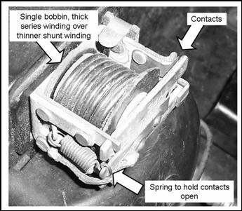
There have been a number of variants during the period over which the cars were manufactured. However, they all have the same function and all have very similar operation. Each Cut-out has a set of spring loaded contacts mounted on a mechanical rocker, known as an armature, plus two electromagnets which are arranged so as to pull and push on this armature. One electromagnet is connected between the dynamo output terminal “D” and earth, (the “shunt” winding”), and the other, (the “series” winding) is connected in series with the battery usually marked “A” and the cut-out contacts. Note that, depending on cut-out type, these windings may be on separate bobbins or combined on one bobbin. Irrespective of type, the shunt winding is composed of many turns of thin wire, whilst the series winding is very few turns of substantially thicker wire.
Example cut-out circuit

With the engine stationary, it is necessary for the battery to be disconnected from the dynamo, to prevent the “motor” action described above. Hence, the contacts must be open. This is the resting state of the cut-out.
As the engine is started and the revs increased, the dynamo output voltage will rise. This output voltage appears across the shunt winding, making it act as an electromagnet. As the series winding has one end connected to an open contact, it plays no part at this stage. Eventually, (at fast tickover), the dynamo voltage will reach a value that would be high enough to prevent current flowing from the battery to the dynamo, but would allow current to flow from the dynamo to the battery – the normal charging method. The shunt winding is arranged so that when the dynamo output voltage reaches this value, it produces a sufficiently strong magnetic field to pull on the armature overcoming the spring force and close the contacts. The battery is now being charged. For 6V systems, this should occur at approximately 6.5V; for 12V, this occurs at 13.5V. As soon as the contacts are closed, the shunt winding is now also connected across the battery. This gives a latching action as the battery now also supplies current for the shunt winding. In this state, the contacts would still be pulled shut until the battery voltage dropped to a low level irrespective of the dynamo output, as the electromagnet is now being operated by the battery.
Consequently, it is necessary to counteract this force so that the spring can pull the contacts apart to disconnect the battery. This is the function of the second or “series” winding.
The Series winding produces a force on the armature which is proportional to the current flowing either to or from the battery, and which changes direction with the direction of current flow. When the battery is being charged, the force acts to add to the pulling force from the shunt winding, causing the contacts to be held firmly shut. However, when the dynamo output falls so that there is a current from the battery to the dynamo, the force is now in the opposite direction and opposes that of the shunt winding. When the force from the series winding equals that of the shunt, then the armature is released for the spring to open the contacts.
If the engine is stopped at this point, the battery is safely disconnected from the dynamo. If the revs rise, the force from the shunt winding will close the contacts again.
This can be seen in operation from the behaviour of the ammeter. With all other electrical loads off, (note that the ammeter measures all current flow from the battery, not just that to the dynamo), and the engine running at a fast tickover, the ammeter will settle in the charging side of the scale. When the revs are allowed to drop, the ammeter will move to the discharge side and then suddenly fall back nearer to zero. This sudden fall back occurs when the series winding has sufficient current flowing in the discharge direction to counteract the closing force from the shunt winding and the contacts are opened. The charging warning light will operate at the same time. No current flows to the dynamo; the remaining discharge shown is actually the current required by the ignition circuit.
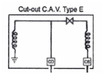

Type E 1922-1923
Type CF1 1924-1931

Type CF3 1931-1933
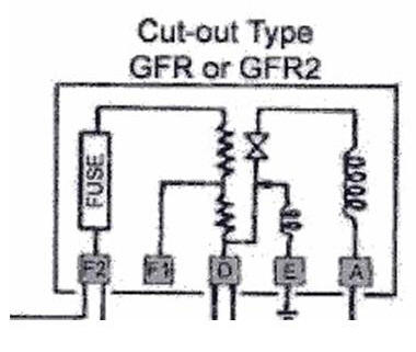
Type GFR or GFR2
1934-1937
This article, written by Geoff Hardman, originally appeared in CA7C Seven Focus in Nov 2006 pp6-8.
XXX . XXX 4 zero How Voltage Regulators Work
Voltage Regulators
As you may recall from last month's article on the function of generators in your classic car, there is no means of internally controlling the output of one. In other words, the faster it spins the more voltage goes into the car's electrical system. If this weren't controlled the generator would damage the battery and burn out the car's lights. Also, if the generator weren't cut out from the car's circuitry when not running, the battery would discharge through its case.

That's where the REGULATOR (commonly called the Voltage Regulator, but that's only one component of the system) comes in. Regulators have seen many design improvements over the decades, but the most commonly used electro-mechanical regulator is the three-control units in one box type. Let's look at how these things work...
Cutout Relay
Sometimes called the circuit breaker, this device is a magnetic "make-and-break" switch. It connects the generator to the battery (and therefore the rest of the car) circuit when the generator's voltage builds up to the desired value. It disconnects the generator when it slows down or stops.
The relay has an iron core that is magnetized to pull down a hinged armature. When the armature is pulled down a set of contact points closes and the circuit is completed. When the magnetic field is broken (like when the generator slows down or stops) a spring pulls the armature up, breaking the contact points.

An obvious failure mode is the contact points. As they open and close, a slight spark is generated, eventually eroding the material on the points until they either "weld" themselves together or become so high in resistance that they won't conduct current when closed. In the first case the battery would discharge through the generator overnight and in the second there would be no charging to the system.
Voltage Regulator
Another iron core-operated set of contact points is utilized to regulate maximum and minimum voltage at all times. This circuit also has a shunt circuit (a shunt re-directs electrical flow) going to ground through a resistor and placed just ahead (electrically) of the points. When the points are closed the field circuit takes the "easy" route to ground but when the points are open the field circuit must pass through the resistor to get to ground.
The field coil on the generator is connected to one of the voltage regulator contact points. The other point leads directly to ground.
When the generator is operating (battery low or a number of devices running) its voltage may stay below that for which the control is set. Since the flow of current will be too weak to pull the armature down the generator field will go to ground through the points. However, if the system is fully charged the generator voltage will increase until it reaches the maximum limit and current flow through the shunt coil will be high enough to pull the armature down and separate the points.
This cycle is repeated over and over in real time. The points open and close about 50 to 200 times per second, maintaining a constant voltage in the system.
Current Regulator
Even though the generator's voltage is controlled it is possible for its current to run too high. This would overheat the generator, so a current regulator is incorporated to prevent premature failure.
Similar in appearance to the voltage regulator's iron core, the current regulator's core is wound with a few turns of heavy wire and connected in series with the generator's armature.

In operation, current flow increases to the predetermined setting of the unit. At this time, current flow through the heavy wire windings will cause the core to draw the armature down, opening the current regulator points. In order to complete the circuit the field circuit must pass through a resistor. This lowers current output, points close, output increases, points open, output down, points close, and so on. The points, therefore, vibrate open and closed much as the voltage regulator's points do, many times every second.
Good and Bad News
Because they are mechanical, voltage regulators are easy to troubleshoot. If you study the function of each of the three parts and how they interrelate, it becomes obvious which part is malfunctioning, depending upon symptoms. That means anyone who understands how everything works can easily troubleshoot problems. That's the good news.
The bad news is that the point gaps and spring pressures determine the voltage/current limits and they are exceedingly hard to adjust. Sometimes it can be done on the car using a voltmeter, but generally it is best to replace the entire regulator assembly when a certain part of it fails. Factory assembly of regulators required relatively sophisticated measurement instruments. Adjusting them by "feel" is a matter of luck, and frequently can result in damage.
Overall, the good news is that regulators are inexpensive and relatively easy to find. Replacement is always a good idea.
What about Alternator Regulators?
The same type of regulator was originally incorporated into alternator-fitted cars and they work in much the same way. However, since some cars used ammeters no current regulator was needed. Therefore, a "single unit" regulator was used to turn on the alternator's stator windings. It was just a regulator without a current regulator section.
It wasn't long thereafter that the automobile companies converted to transistor voltage regulators. Utilizing Zener diodes, transistors, resistors, a capacitor and a thermistor, these regulators maintain proper voltage and current flow throughout the system. Their circuitry operates as fast as 2,000 times per second and they are tremendously reliable. On the other hand, these regulators aren't easy to repair. They are designed to be thrown away and replaced.
Many "solid state" regulators are mounted inside the alternator and are not serviceable other than the ability to set the voltage limits. That's okay, because they work very well for long periods of time. To check their operation, just measure the battery voltage while the engine is off, then when it's running. You should see something between 13 and 15 volts when running. No change in voltage means either the regulator or alternator isn't working, while higher voltage means the regulator isn't properly "regulating."
What about Converting from Generators to Alternators?
Well, that's a double-sided question. We believe such conversions should be done if additional electrical devices have been installed during restoration or major updating of the car. Air conditioning, electric cooling fans, etc. eat up lots of current that can't be easily handled by old generators. Alternators provide three times the current and weigh much less than their old counterparts.
On the other hand, converting to an alternator will affect the car's "period" appearance. It's a personal choice, of course, but one worth considering. We'll be doing an article on a conversion very soon.
XXX . XXX 4 zero null How Automotive Relays and Fuses Work
We've gone through basic theory and major components over the last several articles, so by now you should be fairly comfortable with overall circuitry. Now, we'll cover just a few more common devices and then draw a simple circuit and follow an electron through it. Ready?
Relays:
This was touched-on before but it's worth special attention. Remember that certain devices require considerable current (amps) and that, in turn, require thicker wire. High current devices require big, heavy switches to handle the current. Unfortunately, these would be ugly and expensive, so engineers use relays.
A relay consists of a small coil of wire around a central iron core. When the actuating switch energizes the coil this core moves heavy-duty contacts together, thus allowing high current to be passed to the device. That's how a small switch can control a high-current device.
You already know the starter solenoid is a high-current relay. Other devices that typically utilize relays are the horns, power antenna, air conditioning compressor, power seats, power windows, engine cooling fans, and power tops. Sometimes, headlights and accessory driving lights use them too. It's important to know this because many electrical failures occur in the relays themselves!
Automotive Fuses:
Almost everything in a car is wired through a fuse. Fuses are designed to fail when too much current is drawn through the device. This prevents heating of the wires and subsequent melting of the insulation, followed usually by fire!
Fuses are simple in design. Inside a fuse is a soft wire with a specific cross-sectional thickness. This dimension dictates how many amps can be carried before the wire melts. Too many amps and the fuse fails, saving the rest of the circuit from damage. Pretty neat, huh?
Most of any car's fuses are located in the fuse panel, but some are in-line. In-line fuses are found under the dash and in the engine compartment.
Fusible Links, another kind of fuse, are used in many cars and are almost always found in the wiring harness in the engine compartment. These are molded, single-purpose links in the wire which are designed to melt under extreme conditions (usually a crash which might crush wires together, causing a huge short circuit). Your car's schematic will show their use and location.
Let's look at a fairly typical horn circuit and see how various components are put together to form a working system:

Horn Relay Diagram
Notice that battery voltage travels through a high current wire (red) through the relay to the horn and also through a smaller wire (blue) through the ignition switch to the relay's low-current coil. The first thing you should be aware of is that the horn circuit is always "hot" or "live" when the ignition switch is turned on and all that's needed is a path to ground.
That path is completed when you push in the horn button. When the button is pushed the ground connection is made, energizing the relay's coil "A". The coil's iron core (in this particular design) pulls down arm, connecting high-current contacts "B". High current then flows from the battery to the horn (the horn is connected to ground because it's mounted to the chassis of the car). See how it works?
Actually, one thing is missing from this circuit. There has to be a fuse somewhere in the circuit! The high-current wire from the battery might go through an appropriate fuse on the fuse panel or there might be an in-line fuse near the horns (it depends upon the production engineering decisions as to the most economical placement, but your schematic drawing will show its location).
Also, your car's designers might have fused the low-current side of the relay as well. Check the schematic.
Suppose the horns don't work. Where do you start your troubleshooting? Here's a good procedure:
1. Check the fuses.
2. Check for voltage to the horns at the horn connector. Push the horn button or jump the wire to ground to actuate the relay. If you have voltage the horns should be operable, so search elsewhere for the problem.
3. Check for voltage at the horn button. While there, check to be sure the button's contacts touch each other when pushed. If everything's ok, go to the relay.
4. With someone pushing the horn button, check for voltage (on the low-current wire coming from the dash) on the relay. If there is voltage, the relay isn't working, right?
That's right. Now you have isolated the problem to the relay and only two things can be wrong: either the relay's coil isn't energizing (due to an internal broken wire) or the high-current contacts are being drawn together but no current is passing through (remember high-resistance connections?). If the coil is bad the relay must be replaced. If the contacts are charred, file them smooth.
Conclusion:
Automotive circuits are quite simple in design. Remember always that the factory used as little wire as possible, so look at the schematic diagram to see where multiple connections are made. Remember also that your friendly electron travels through several devices on its way to doing its work so you need to systematically trace the path.
Schematic diagrams are printed way too small in the manuals. Take your drawings to a copier that enlarges and blow them up to easily-readable size. Tape all the sheets together into one big drawing an you will find that tracing electrical paths becomes very straightforward.
With a little practice and patience you will no longer fear your car's electrical system.
XXX . XXX 4 zero null 0 Charging Systems
charging system or dynamo ampere
What is a Charging System?
The modern charging system hasn't changed much in over 40 years. It consists of the alternator, regulator (which is usually mounted inside the alternator) and the interconnecting wiring.
The purpose of the charging system is to maintain the charge in the vehicle's battery, and to provide the main source of electrical energy while the engine is running.
If the charging system stopped working, the battery's charge would soon be depleted, leaving the car with a "dead battery." If the battery is weak and the alternator is not working, the engine may not have enough electrical current to fire the spark plugs, so the engine will stop running.
If the battery is "dead", it does not necessarily mean that there is anything wrong with it. It is just depleted of its charge. It can be brought back to life by recharging it with a battery charger, or by running the engine so that the alternator can charge .
The main component in the charging system is the ALTERNATOR. The alternator is a generator that produces Alternating Current (AC), similar to the electrical current in your home. This current is immediately converted to Direct Current (DC) inside the alternator. This is because all modern automobiles have a 12 volt, DC electrical system.
A VOLTAGE REGULATOR regulates the charging voltage that the alternator produces, keeping it between 13.5 and 14.5 volts to protect the electrical components throughout the vehicle.
There is also a system to warn the driver if something is not right with the charging system. This could be a dash mounted voltmeter, an ammeter, or more commonly, a warning lamp. This lamp is variously labeled "Gen" Bat" and "Alt.". If this warning lamp lights up while the engine is running, it means that there is a problem in the charging system, usually an alternator that has stopped working. The most common cause is a broken alternator drive belt.
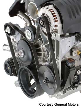 The alternator is driven by a belt that is powered by the rotation of the engine. This belt goes around a pulley connected to the front of the engine's crankshaft and is usually responsible for driving a number of other components including the water pump, power steering pump and air conditioning compressor. On some engines, there is more than one belt and the task of driving these components is divided between them. These belts are usually referred to as: Fan Belt, Alternator Belt, Drive Belt, Power Steering Belt, A/C Belt, etc. More common on late model engines, one belt, called a Serpentine Belt will snake around the front of the engine and drive all the components by itself.
On engines with separate belts for each component, the belts will require periodic adjustments to maintain the proper belt tension. On engines that use a serpentine belt, there is usually a spring loaded belt tensioner that maintains the tension of the belt, so no periodic adjustments are required. A serpentine belt is designed to last around 30,000 miles. Check your owner's manual to see how often yours should be replaced.
Alternator output is measured in both voltage and amperage. To understand voltage and amperage, you must also know about resistance, which is measured in ohms. An easy way to picture this is to compare the movement of electricity to that of running water. Water flows through a pipe with a certain amount of pressure. The size (diameter) of the pipe dictates how much resistance there will be to the flowing water. The smaller the pipe, the more resistance. You can increase the pressure to get more water to flow through, or you can increase the size of the pipe to allow more water to flow using less pressure. Since too much pressure can burst the pipe, we should probably restrict the amount of pressure being used. You get the idea, but how is this related to the flow of electricity?
Well, voltage is the same as water pressure. Amperage is like the amount or volume of water flowing through, while resistance is the size of the wire transmitting the current. Since too much voltage will damage the electrical components such as light bulbs and computer circuits, we must limit the amount of voltage. This is the job of the voltage regulator. Too much water pressure and things could start breaking. Too much voltage and things could start burning out.
Let's get technical
Now, let's go a little deeper and see how these charging system components actually work to produce the electrical power that a modern automobile requires.
The Alternator
 The alternator uses the principle of electromagnetism to produce current. The way this works is simple. If you take a strong magnet and pass it across a wire, that wire will generate a small voltage. Take that same wire and loop it many times, than if you pass the same magnet across the bundle of loops, you create a more sizable voltage in that wire.
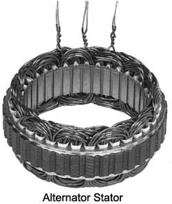
There are two main components that make up an alternator. They are the rotor and the stator. The rotor is connected directly to the alternator pulley. The drive belt spins the pulley, which in turn spins the rotor. The stator is mounted to the body of the alternator and remains stationary. There is just enough room in the center of the stator for the rotor to fit and be able to spin without making any contact.
The stator contains 3 sets of wires that have many loops each and are evenly distributed to form a three phase system. On some systems, the wires are connected to each other at one end and are connected to a rectifier assembly on the other end. On other systems, the wires are connected to each other end to end, and at each of the three connection points, there is also a connection to the rectifier. More on what a rectifier is later.
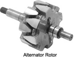 The rotor contains the powerful magnet that passes close to the many wire loops that make up the stator. The magnets in the rotor are actually electro magnets, not a permanent magnets. This is done so that we can control how much voltage the alternator produces by regulating the amount of current that creates the magnetic field in the rotor. In this way, we can control the output of the alternator to suit our needs, and protect the circuits in the automobile from excessive voltage.
Now we know that every magnet has a north and a south pole and electro magnets are no exception. Our rotor has two interlocking sections of electro magnets that are arranged so that there are fingers of alternating north and south poles. that are evenly distributed on the outside of the rotor.
When we spin the rotor inside the stator and apply current to the rotor through a pair of brushes that make constant contact with two slip rings on the rotor shaft. This causes the rotor to become magnetized. The alternating north and south pole magnets spin past the three sets of wire loops in the stator and produce a constantly reversing voltage in the three wires. In other words, we are producing alternating current in the stator.
Now, we have to convert this alternating current to direct current current. This is done by using a series of 6 diodes that are mounted in a rectifier assembly. A diode allows current to flow only in one direction. If voltage tries to flow in the other direction, it is blocked. The six diodes are arranged so that all the voltage coming from the alternator is aligned in one direction thereby converting AC current into DC current.
 There are 2 diodes for each of the three sets of windings in the stator. The two diodes are facing in opposite directions, one with its north pole facing the windings and the other with its south pole facing the windings. This arrangement causes the AC current coming out of the windings to be converted to DC current before it leaves the alternator through the B terminal. Connected to the B terminal of the alternator is a fairly heavy wire that runs straight to the battery.
Current to generate the magnetic field in the rotor comes from the ignition switch and passes through the voltage regulator. Since the rotor is spinning, we need a way to connect this current from the regulator to the spinning rotor. This is accomplished by wires connected to two spring loaded brushes that rub against two slip rings on the rotor's shaft. The voltage regulator monitors the voltage coming out of the alternator and, when it reaches a threshold of about 14.5 volts, the regulator reduces the current in the rotor to weaken the magnetic field. When the voltage drops below this threshold, the current to the rotor is increased.
There is another circuit in the alternator to control the charging system warning lamp that is on the dash. Part of that circuit is another set of diodes mounted inside the alternator called the diode trio. The diode trio takes current coming from the three stator windings and passes a small amount through three diodes so that only the positive voltage comes through. After the diodes, the wires are joined into one wire and sent out of the alternator at the L connection. It then goes to one side of the dash warning lamp that is used to tell you when there is a problem with the charging system. The other side of the lamp is connected to the run side of the ignition switch. If both sides of the warning lamp have equal positive voltage, the lamp will not light. Remove voltage from one side and the lamp comes on to let you know there is a problem.
This system is not very efficient. There are many types of malfunctions of the charging system that it cannot detect, so just because the lamp is not lit does not mean everything is ok. A volt meter is probably the best method of determining whether the charging system is working properly
The Voltage Regulator
The voltage regulator can be mounted inside or outside of the alternator housing. If the regulator is mounted outside (common on some Ford products) there will be a wiring harness connecting it to the alternator.
The voltage regulator controls the field current applied to the spinning rotor inside the alternator. When there is no current applied to the field, there is no voltage produced from the alternator. When voltage drops below 13.5 volts, the regulator will apply current to the field and the alternator will start charging. When the voltage exceeds 14.5 volts, the regulator will stop supplying voltage to the field and the alternator will stop charging. This is how voltage output from the alternator is regulated. Amperage or current is regulated by the state of charge of the battery. When the battery is weak, the electromotive force (voltage) is not strong enough to hold back the current from the alternator trying to recharge the battery. As the battery reaches a state of full charge, the electromotive force becomes strong enough to oppose the current flow from the alternator, the amperage output from the alternator will drop to close to zero, while the voltage will remain at 13.5 to 14.5. When more electrical power is used, the electromotive force will reduce and alternator amperage will increase. It is extremely important that when alternator efficiency is checked, both voltage and amperage outputs are checked. Each alternator has a rated amperage output depending on the electrical requirements of the vehicle.
The charging system gauge or warning lamp monitors the health of the charging system so that you have a warning of a problem before you get stuck.
When a charging problem is indicated, you can still drive a short distance to find help unlike an oil pressure or coolant temperature problem which can cause serious engine damage if you continue to drive. The worst that can happen with a charging system problem is that you get stuck in a bad location.
A charging system warning lamp is a poor indicator of problems in that there are many charging problems that it will not recognize. If it does light while you are driving, it usually means the charging system is not working at all. The most common cause of this is a broken alternator belt.
There are two types of gauges used to monitor charging systems on some vehicles: a voltmeter which measures system voltage and an ammeter which measures amperage. Most modern cars that have gauges use a voltmeter because it is a much better indicator of charging system health. A mechanic's voltmeter is usually the first tool a technician uses when checking out a charging system
 A modern automobile has a 12 volt electrical system. A fully charged battery will read about 12.5 volts when the engine is not running. When the engine is running, the charging system takes over so that the voltmeter will read 14 to 14.5 volts and should stay there unless there is a heavy load on the electrical system such as wipers, lights, heater and rear defogger all operating together while the engine is idling at which time the voltage may drop. If the voltage drops below 12.5, it means that the battery is providing some of the current. You may notice that your dash lights dim at this point. If this happens for an extended period, the battery will run down and may not have enough of a charge to start the car after shutting it off. This should never happen with a healthy charging system because as soon as you step on the gas, the charging system will recharge the battery. If the voltage is constantly below 14 volts, you should have the system checked. If the voltage ever goes above 15 volts, there is a problem with the voltage regulator. Have the system checked as soon as possible as this "overcharging" condition can cause damage to your electrical system.
 If you think of electricity as water, voltage is like water pressure, whereas amperage is like the volume of water. If you increase pressure, then more water will flow through a given size pipe, but if you increase the size of the pipe, more water will flow at a lower pressure. An ammeter will read from a negative amperage when the battery is providing most of the current thereby depleting itself, to a positive amperage if most of the current is coming from the charging system. If the battery is fully charged and there is minimal electrical demand, then the ammeter should read close to zero, but should always be on the positive side of zero. It is normal for the ammeter to read a high positive amperage in order to recharge the battery after starting, but it should taper off in a few minutes. If it continues to read more than 10 or 20 amps even though the lights, wipers and other electrical devices are turned off, you may have a weak battery and should have it checked.
There are a number of things that can go wrong with a charging system:
- Insufficient Charging OutputIf one of the three stator windings failed, the alternator would still charge, but only at two thirds of its normal output. Since an alternator is designed to handle all the power that is needed under heavy load conditions, you may never know that there is a problem with the unit. It might only become apparent on a dark, cold rainy night when the lights, heater, windshield wipers and possible the seat heaters and rear defroster are all on at once that you may notice the lights start to dim as you slow down. If two sets of windings failed, you will probably notice it a lot sooner
It is more common for one or more of the six diodes in the rectifier to fail. If a diode burns out and opens one of the circuits, you would see the same problem as if one of the windings had failed. The alternator will run at a reduced output. However, if one of the diodes were to short out and allow current to pass in either direction, other problems will occur. A shorted diode will allow AC current to pass through to the automobile's electrical system which can cause problems with the computerized sensors and processors. This condition can cause the car to act unpredictably and cause all kinds of problems. - Too much voltageA voltage regulator is designed to limit the voltage output of an alternator to 14.5 volts or less to protect the vehicle's electrical system. If the regulator malfunctions and allows uncontrolled voltage to be released, you will see bulbs and other electrical components begin to fail. This is a dangerous and potentially costly problem. Fortunately, this type of failure is very rare. Most failures cause a reduction of voltage or amperage.
- NoiseSince the rotor is always spinning while the engine is running, there needs to be bearings to support the shaft and allow it to spin freely. If one of those bearings were to fail, you will hear a grinding noise coming from the alternator. A mechanic's stethoscope can be used to confirm which of the spinning components driven by the serpentine belt is making the noise.
The most common repair is the replacement of the alternator with a new or rebuilt one. A properly rebuilt alternator is as good as a new alternator and can cost hundreds less than purchasing a brand new one.
Labor time to replace an alternator is typically under an hour unless your alternator is in a hard to access location. Most alternators are easily accessible and visible on the top of the engine.
Replacing an alternator is usually an easy task for a backyard mechanic and rebuilt alternators are readily available for most vehicles at the local auto parts store. The most important task for the do-it-yourselfer is to be careful not to short anything out. ALWAYS DISCONNECT THE BATTERY BEFORE REPLACING AN ALTERNATOR.
Alternators can be repaired by a knowledgeable technician, but in most cases, it is not economical to do this. Also, since the rest of the alternator is not touched, a repair job is usually not guaranteed.
In some cases, if the problem is diagnosed as a bad voltage regulator, the regulator can be replaced without springing for a complete rebuild. The problem with this is that there will be an extra labor charge for disassembling the alternator in order to get to the internal regulator. That extra cost, along with the cost of the replacement regulator, will bring the total cost close to the cost of a complete (and guaranteed) rebuilt.
This is not the case when the regulator is not inside the alternator. In those cases, the usual practice is to just replace the part that is bad.
As the dynamo and battery are connected together, there has to be some means of stopping current running from the battery to the dynamo when the vehicle is switched off. This is what the cut out does.
The cut out is a coil of wire wound around a soft iron core and is therefore, an electromagnet. When the car is started current from the dynamo will flow in this coil, magnetising the soft iron core. When the current reaches a level greater than the static battery volts, the magnetism reaches sufficient strength to pull together a set of contacts that connect the dynamo to the battery. In this way the cut out ensures that current can only flow from the dynamo to the battery and not the other way around. This function is performed by diodes in the alternators of modern cars. Most cut outs are set to cut in at 14.3 dynamo volts.
When the car is switched off the dynamo stops producing current and the magnetism in the cut out coil collapses, opening the contacts and disconnecting the dynamo from the battery.
essentially an old fashioned voltage regulator .
The other type is a cut out switch used in racing to disable the alternator and get a little more horsepower.
It is usually a switch installed in the field circuit of the alternator. Switching it off stops the magnetic field and stops the alternator from producing electricity.
XXX . XXX 4 zero null 0 1 2 Cutout
| While driving and using an original cutout, periodically check the Ammeter to see if the system is charging. The Ammeter can be used for a quick check for the cutout. With all electrical accessories off, the Ammeter should read to the right while driving, and zero when the engine is at low idle or turned off. | ||
The Cutout In its simplicity a cutout is a magnetically controlled switch that provides a path for current flow from the generator to the battery. The cutout permits charging of the battery when the engine is running and prevents the battery from discharging when not. |  | |
| The Coils Inner Coil-The inner coil is made up of multiple windings of a thin wire around an iron core. The fine-wire winding is just enough to get the points to close when the generator voltage rises above 6.2V or so. Its only purpose is to create a magnetic field to pull on the armature until the contact points close. By itself the magnetic field created by the inner coil is not strong enough to keep the points closed when subject to vibrating. Once the points close, the heavy-wire (Outer Coil) begins to conduct, creating a strong magnetic field that aids the inner coil in keeping the contacts firmly closed. Outer Coil-The outer coil is made with a heavy wire and few windings. With the points closed current from the generator travels thru the outer coil charging the battery and strengthening the magnetic field around the iron core which prevents the points from vibrating open. |  | |
| The Points Contact Points-The contact points of the cutout act as a switch and are held “Normally Open” by the armature spring. When the speed of the generator increases a magnetic field is created closing the points, thus, allowing current from the generator to flow and charge the battery. If the generator voltage drops below battery voltage, such that the battery begins to "charge" the generator ,instead of the other way around, the current in the heavy winding will be reversed, which means it's magnetic field will work AGAINST the fine winding, and cause the points to open. The point of "cut-in" (closure of points) is determined by the tension of the armature spring and the air gap between the iron core and contact arm. The contact points should close when the voltage of the generator has reached 6.1 to 6.3 volts. It is possible to change the "cut-in" by adjusting the air gap and/or bending the Armature Spring. (The "cut-in" charges the battery) The point of "cut-out" (opening of points) is determined by the tension of the Armature Spring. The air gap between the contact arm and the iron core has little or no effect on the "cut-out". The cutout should occur when the ammeter reads between 0 and 2 amps. It is possible to change the "cut-out" by bending the Armature Spring, set the "cut-out" as close to 0 as possible to prevent points from arcing and burning out. (The "cut-out"stops the charging of the battery and prevents the battery from draining) |  | |
Testing Cutout On Car Equipment: • 3/4 Ohm Resistor • DC voltmeter
|  | |
To Adjust
| ||
 | ||

XXX . XXX 4 zero null 0 1 2 3 AUTO RESET OVER/ UNDER VOLTAGE CUT- OUT
This over/under voltage cut-out will save your costly electrical and electronic appliances from the adverse effects of very high and very low mains voltages.
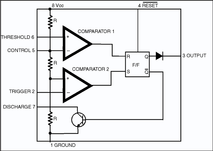
The circuit features auto reset and utilises easily available components. It makes use of the comparators available inside 555 timer ICs. Supply is tapped from different points of the power supply circuit for relay and control circuit operation to achieve reliability.
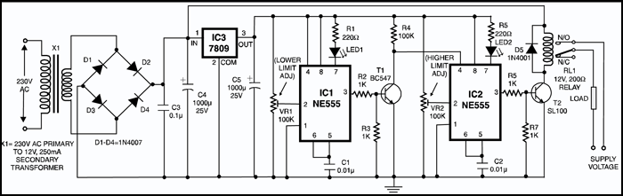
The circuit utilises comparator 2 for control while comparator 1 output (connected to reset pin R) is kept low by shorting pins 5 and 6 of 555 IC. The positive input pin of comparator 2 is at 1/3rd of Vcc voltage. Thus as long as negative input pin 2 is less positive than 1/3 Vcc, comparator 2 output is high and the internal flip-flop is set, i.e. its Q output (pin 3) is high. At the same time pin 7 is in high impedance state and LED connected to pin 7 is therefore off. The output (at pin 3) reverses (goes low) when pin 2 is taken more positive than 1/3 Vcc. At the same time pin 7 goes low (as Q output of internal flip-flop is high) and the ED connected to pin 7 is lit. Both timers (IC1 and IC2) are configured to function in the same fashion.
Preset VR1 is adjusted for under voltage (say 160 volts) cut-out by observing that LED1 just lights up when mains voltage is slightly greater than 160V AC. At this setting the output at pin 3 of IC1 is low and transistor T1 is in cut-off state. As a result RESET pin 4 of IC2 is held high since it is connected to Vcc via 100 kilo-ohm resistor R4.
Preset VR2 is adjusted for over voltage (say 270V AC) cut-out by observing that LED2 just extinguishes. when the mains voltage is slightly less than 270V AC. With RESET pin 4 of IC2 high, the output pin 3 is also high. As a result transistor T2 conducts and energises relay RL1, connecting load to power supply via its N/O contacts. This is the situation as long as mains voltage is greater than 160V AC but less than 270V AC.
When mains voltage goes beyond 270V AC, it causes output pin 3 of IC2 to go low and cut-off transistor T2 and de-energise relay RL1, in spite of RESET pin 4 still being high. When mains voltage goes below 160V AC, IC1’s pin 3 goes high and LED1 is extinguished. The high output at pin 3 results in conduction of transistor T1. As a result collector of transistor T1 as also RESET pin 4 of IC2 are pulled low. Thus output of IC2 goes low and transistor T2 does not conduct. As a result relay RL1 is de-energised, which causes load to be disconnected from the supply. When mains voltage again goes beyond 160V AC (but less than 270V AC) the relay again energises to connect the load to power supply.
XXX . XXX 4 zero null 0 1 2 3 Electronics cut out ( Auto timer electronics )
Description
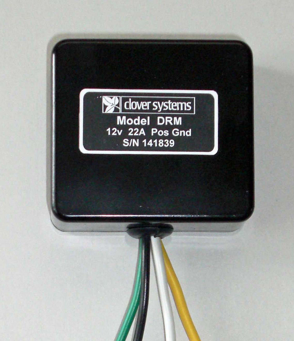
The Clover Systems Dynamo Regulator is an all-electronic voltage and current regulator for DC generators used in pre-1970 motor vehicles. It can be used in vintage cars, motorcycles, trucks, tractors and boats.
Replace your old mechanical regulator with an all-electronic regulator that never requires cleaning or adjustment. Don’t waste your money on used or aftermarket mechanical replacements. This control box will be trouble free for the life of your car.
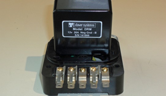
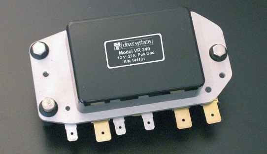
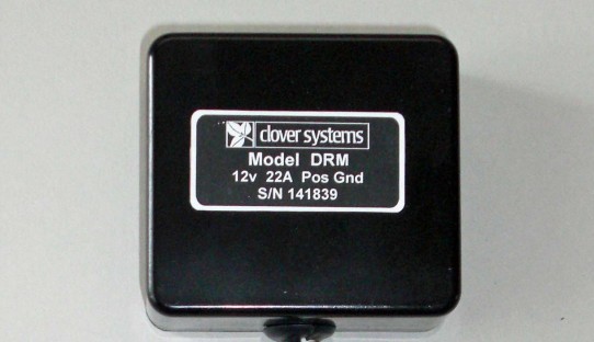
This Electronic Dynamo Regulator is available in four configurations:
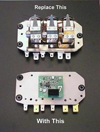
DR340
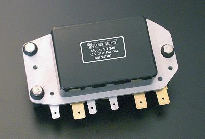
 Exact replacement for Lucas RB 340. Original appearance with Lucas cover Heavy Duty aluminum and stainless steel construction
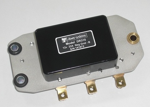
DR310
Exact replacement for Lucas RB 310. Available with screw terminals or push-on connectors Original appearance with Lucas cover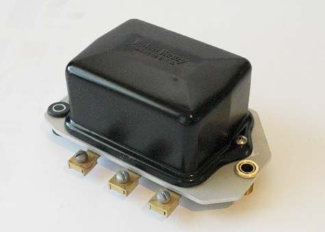
DR110
Exact replacement for many Delco and Autolite regulators. Original appearance with Delco cover Heavy Duty aluminum and stainless steel construction
Clover Systems Electronic Dynamo Regulators are compatible with most DC generators, including Autolite, Bosch, Delco, Ford, Lucas, and many others, including Ducellier, Eclipse, Harley-Davidson, Magneti-Marelli, Paris-Rhone, and Rotax. Vehicles include most pre-1970 cars, motorcycles, trucks, tractors, and boats.
The DR340 and DR310 are designed to be an exact replacements for Lucas RB340 and RB310 regulators used in many European autos. The D110 is designed to replace many Delco, Autolite, Bosch, and Ford regulators. The DRM Module can be Installed inside your original regulator case, retaining 100% original appearance.
A complete list of compatible models is too lengthy, so please contact us if you have any questions. The regulator can be configured to match your generator, including polarity, voltage, and current limit.
More Reliable than a mechanical regulator, as well as many other electronic models. All critical components are Automotive Grade AEC-Q101 qualified, and rated to 150°C (300°F). Complete units feature heavy-duty CNC machined aluminum and stainless steel construction.
More Consistent and repeatable performance than mechanical regulators that can change from day to day or moment to moment.
Starts Charging at a low RPM. Supplies current whenever the dynamo output exceeds the battery voltage, regardless of what that voltage is. Vehicle can run without a battery.
High Efficiency means it runs cooler than a mechanical regulator. Dissipates less than 2W @22A, and 5W @ 35A. HP version can easily handle 55A.
Impervious to Shock & Vibration as well as magnetic fields and gravity, so you can mount it anywhere.
Cleaner Switching means less electrical noise and radio interference.
The mechanical units’ relay contacts wear, get contaminated, and burn. This requires cleaning and filing the contacts, and then re-adjusting the voltage limit, current limit, and cut-in voltage.
With the Clover Systems all-electronic control box, there is never any need for maintenance. Our regulators come factory configured for your dynamo, and so no adjustment is necessary at installation.
The mechanical control boxes have a fixed cut-in and cut-out voltage. The dynamo has to get up to the cut-in voltage before the dynamo can supply any power. Furthermore, when the dynamo voltage is below the battery voltage, but above the cut-out voltage, current from the battery is fed back to the generator, thus wasting power, overheating the generator, and creating a drag on the engine. With the Clover regulator, the regulator is supplying current whenever the output voltage is grater than the battery voltage.
The Clover Systems design not only eliminates this problem, but uses a super-efficient “ideal diode” circuit that generates far less heat than other electronic units that use a Schottky diode.
The Clover Dynamo Regulator is factory adjusted to match your dynamo. But it is also user adjustable so that your unique requirements can be precisely met. There are many types of automotive batteries these days, and many have special charging voltage requirements.
Car owners and garages will often replace a regulator without adjusting the voltage, current, and cutout because of the difficulty. This will result in poor battery charging, loss of electrical power, and possible damage to the generator or battery.
Exclusive Features
Continuously adjustable voltage and current limits Highest current rating & lowest heat dissipation of any electronic dynamo regulator Works with virtually any DC generator Works with field resistance down to 0.8 ohms. Fully RepairableOther Features
Regulates both voltage and current 2 year warranty High efficiency MOSFET cut-out Works with most DC generators, including Autolite, Bosch, Delco, Ford, Lucas, Rotax, etc. Adjustable voltage & current limits Original appearance when used with original cover Available for 6v, 8v, 12v or 24v, 7A – 55A, Neg or Pos ground Immune to shock & vibration Automotive Grade components rated to 150ºC Fully tested and burned-in at full load The engine will run without a battery. Installation hardware and instructions included Made in USA
All generators work by rotating a loop of wire in a magnetic field. In a dynamo, the magnetic field is created by electromagnets (field coils). Voltage and current are controlled by controlling the current to the field coils. The current through the field coils determines the strength of the magnetic field that the armature rotates in, and thus the output of the generator.
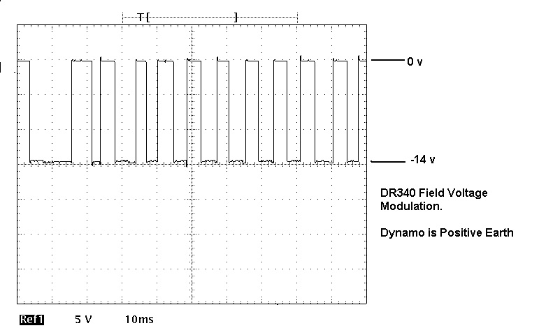
In the Clover Regulator, the output voltage of the generator is compared to a precision voltage reference. When the generator output exceeds this reference, the current to the field coils is cut off. This causes the generator output to fall. When the output falls below the reference voltage, the field current is turned back on. In this way, the field current is modulated at a rate of 50 – 125 Hz. These rapid changes are smoothed out by the inductance of the field coils, thus maintaining a constant output voltage.
Current limiting is accomplished in the same way. Output current is sensed with a Hall-Effect device that detects the magnetic field created by the output current. When the output current exceeds a preset limit, the field current is turned off. Just as with the voltage regulation, the field current is modulated to maintain a constant output current.
Instead of a cut-out relay, we use a MOSFET “ideal diode”, which provides much higher efficiency than Schottky diodes. Power is supplied whenever the dynamo output voltage is greater than the battery voltage, rather than a pre-set voltage as in the mechanical regulator, and battery voltage is never fed back to the dynamo armature.
In the mechanical regulator oscillograph below, note that the field voltage spikes in the opposite direction when the relay contacts are opened. This is due to the stored energy in the field coils. This is similar to what happens in an ignition coil. Most regulators include a load resistor to try to minimize this effect. Also note the relay contact bounce when the relay closes.
In the DR340 Electronic Regulator, the “back-emf” is eliminated by a high-power diode. The result is much cleaner and more efficient switching with reduced radio interference.
 If performance is the only consideration, the alternator is the best choice. It delivers more power, has greater output at lower RPM, weighs less, and is cheaper.
But there are some good reasons to stick with your original dynamo: For one thing, if you don’t need a lot of additional power, there is no reason to go to the bother and expense of changing to an alternator. Furthermore, the conversion will require special mounting brackets and wiring changes.
There are some cases where conversion to alternator is not practical, for instance if your original dynamo is integrated with the steering pump or tachometer feed.
Finally, all-original cars are more valuable than modified cars. If you are a purist, you can keep the charging system completely original by modifying your existing regulator to all-electronic.
Shunt Wound vs. Series Wound
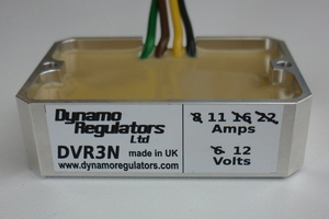
Description and features of the DVR3™
The DVR3™ is a high output, current limited electronic dynamo regulator & cut-out unit to suit dynamos with one end of the field winding connected to the vehicle 'earth'. Such dynamos, including Lucas types, were fitted to many classic cars and other vehicles. (Sometimes known as 'shunt' field, although this terminology is not strictly correct.) Choice of Negative or Positive Earth versions. Maximum current outputs of 8, 11, 16 or 22 Amps (310 Watts) are available to suit 6 or 12 V systems. Higher current, 30 or 40 Amp and custom current limit versions are also available at a modest premium (£10 at present). The field winding resistance of the dynamo must be greater than 2.5 ohms.
This is a modern electronic 'solid state' replacement for the original electromechanical two bobbin 'CVC' regulator units and 3 bobbin type with separate current regulation fitted in Classic Vehicles equipped with dynamo electrical generation. The DVR3 features improved performance over 'relay' types giving excellent charge voltage stability from the lowest revs to maximum speed, and zero low speed battery discharge into the dynamo. (Current limit accuracy is within approximately 5% of nominal current. E.g. a 20 Amp current limit unit will be limited to between 19 and 21 Amps.) The DVR3 is electrically and mechanically robust, housed in a strong aluminium housing for good heat transfer.
DVR3 size is 60 x 42 x 18 mm. The unit produces a very modest degree of heat but proper mounting is recommended to limit temperature rise for maximum service life. It is supplied with an adhesive thermal bonding pad on the top surface, for attaching to a flat (not hot) metal surface to act as a heat-sink. Alternatively a small finned heat-sink is available for higher current versions (22 Amp and above) to achieve enhanced cooling. A pair of vertical holes, with 54 mm centre spacing, M3 clearance (3.2 mm diameter) allow a pair of screws as an alternative (or additional) means to secure the regulator. Connections are by flying leads of approximately 130 mm. Bared wire ends allow the customer to connect using their preferred method.


electronic circuit cut out automotive ( Auto timer )

Make this Voltage Stabilizer Circuit for Your Car
we learn about a car voltage stabilizer circuit which could be made and installed in all cars for ensuring a perfectly controlled and stabilized supply for the associated sensitive electronics and gadgets.
Understanding Car Electrical
A car electrical is probably more volatile than our house electrical, simply because it is generated from a source called alternator whose output considerably varies with the speed of the vehicle.
It means if you are driving your car with sudden changes in its speed or if you are often applying brakes, would consequently generate varying voltages from the alternator outputs.
Since nowadays our car and other vehicle interiors heavily involve sophisticated electronic gadgets, an unstable voltage conditions can cause serious effects on their performance and life.
The circuit idea was requested by Mr.Haziq, let's know more about the making of the proposed circuit (designed by me for the application).
Today we have some wonderful ICs at our disposal which are specifically designed for voltage regulation applications.
The LM317 and the LM338 are a couple of them which are versatile with their voltage regulation functions, I have discussed them elaborately in some my earlier posts.
The LM317 can handle up to 1.5 Amps while its big brother the LM338 can hold not more than 5 Amps.
However these values are quite meager when compared to the huge asks in automobiles.
By suitably modifying the configurations, the IC can be made to regulate any desired levels of currents though.
In the proposed car voltage stabilizer circuit we incorporate the IC LM317 and modify its standard design such that it enables the car electrical with sufficient power and yet restricts it from all possible dangers like overloads, over current, fluctuating voltages and short circuits, providing an ideal voltage conditions for the vehicle interiors.
Circuit Description
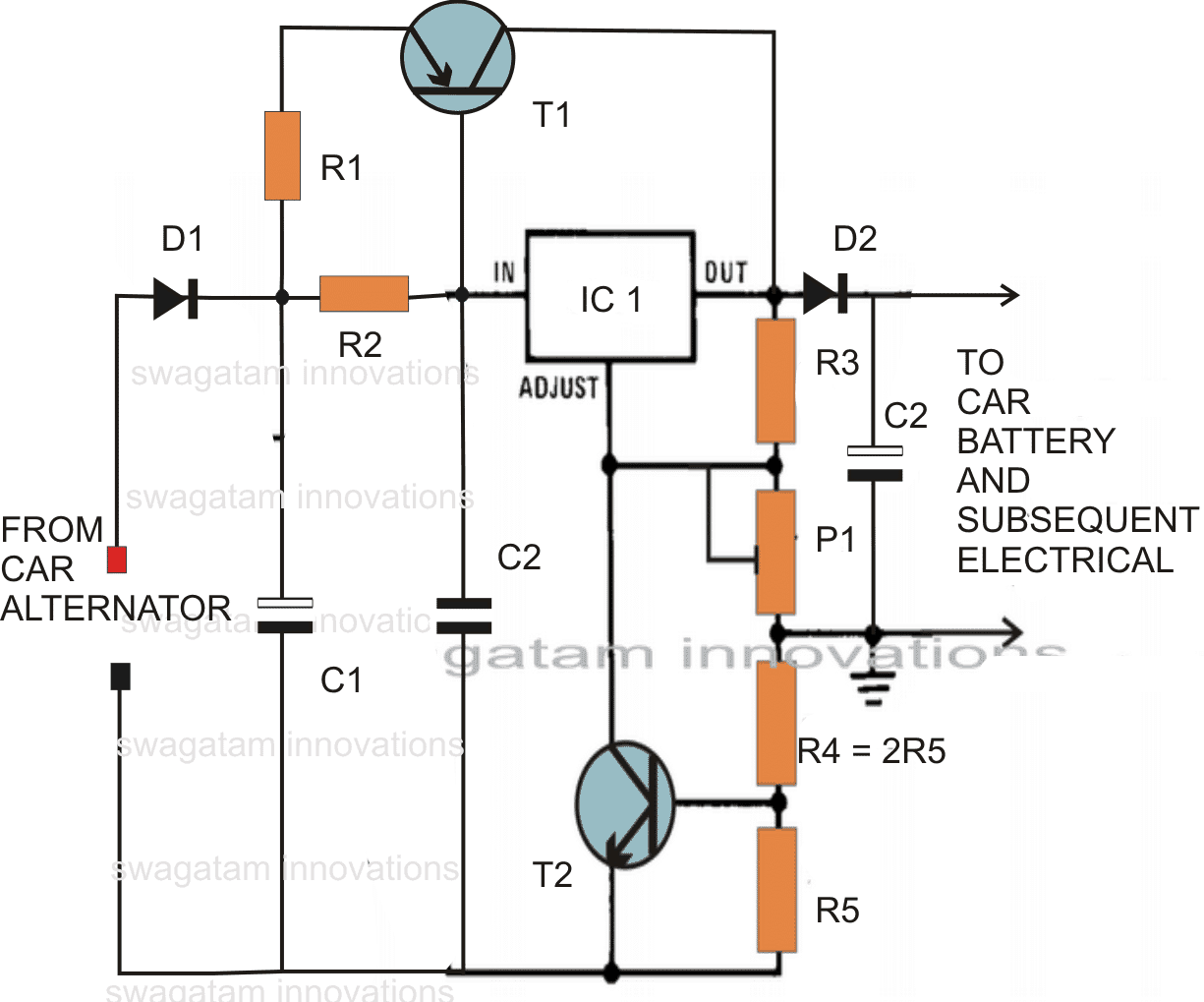
The circuit diagram shows a rather simple configuration where the IC 317 has been wired in its standard voltage regulator mode.
R1 limits the surge current, while R2 decides the triggering voltage to T1, if the current consumption crosses the 1.5 amp mark, T1 conducts and assists the IC by sharing the excess current through it.
P1 is set for achieving around 13 volts across C3.
R5 monitors over load conditions and short circuits, if the current crosses beyond 12 amps, sufficient current develops across R5 to trigger T2, which instantly switches OFF the IC so that the output voltage drops and restricts the current below 12 amps.
Ideal Specifications:
- Constant voltage = 13 volts
- Current Limit = 12 Amp
- Overload protection = above 12 amp cut OFF
- Thermal protection (if the transistor and IC are mounted on the same heatsink with mica isolation)
- Short circuit protection (fire hazard protection)
Parts List
R1 = 0.1 Ohms, 100 watts, made from 1mm iron wire.
R2 = 2 Ohms, 1 watt,
R3 = 120 Ohms, 1/4watts,
R4 = 0.1 Ohms, 20 watts, as explained for R1 (this resistor is actually not required, may be replaced with a wire short.)
R5 = 0.05Ohms, 20 watts, make as R1
T1 = MJ2955 mounted on big finned type heatsink
T2 = BC547,
C1 = 10,000uF, 35V
C2 = 1uF/50V
C3 = 100uF/25V
P1 = 4k7 preset,
IC1 = LM317
D1, D2 = 20 amp diode (3nos. 6 amp diodes in parallel)
Simplified Version
Using the IC LM196, the above configuration becomes extremely simple, you may refer to the following diagram which illustrates a simplified version of the proposed car alternator voltage stabilizer circuit using bare minimum components.
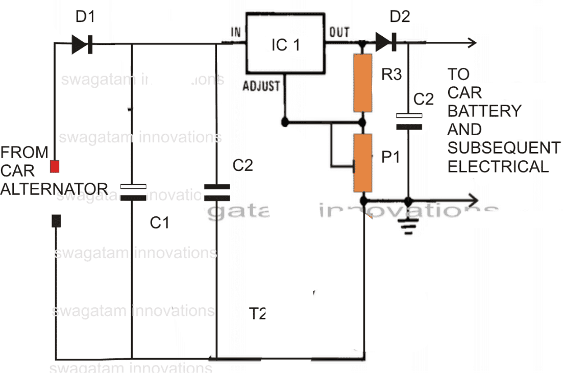
R3 = 240 ohms
D1, D2 = 15 amp diodes
P1 = 10k preset
C1,C2,C3 as specified above
IC1 = LM196
D1, D2 = 15 amp diodes
P1 = 10k preset
C1,C2,C3 as specified above
IC1 = LM196
LT3086 Adjustable Voltage Controlled Current Source
The LT®3086 is a multi-feature, low dropout, low noise 2.1A linear regulator that operates over a 1.4V to 40V input supply range. Dropout voltage at 2.1A is typically 330mV. One resistor sets output voltage from 0.4V to 32V. Output voltage tolerance is guaranteed to ±2% over line, load and temperature. The LT3086 is stable with ceramic output capacitors, requiring a minimum of 10μF. The LT3086’s programmable cable drop compensation cancels output voltage errors caused by resistive connections to the load. A master/slave configuration allows paralleling of multiple devices for higher load current and heat spreading without external ballast resistor requirements. Output current and temperature monitoring along with a power good flag provide system diagnostic and debug capability. Internal fault circuitry includes thermal shutdown and current limit with foldback. Thermal limit and current limit are also externally programmable.
 Adjustable Voltage Controlled Current Source
XXX . XXX 4 zero null 0 1 2 3 4
Today’s manufacturers of automotive fleets and mass transportation systems are motivated to meet fuel efficiency and emission requirements, as well as market demands for reduced costs. e-Mobility (electro mobility or advanced mobility) refers to clean and efficient electric and hybrid vehicles that use electric powertrain technologies, in-vehicle information, communication technologies, and connected infrastructures.
Metros and tramways are electric and provide high-capacity, zero-emission public transport systems in many European cities. Likewise, about 80% of Europe’s mainline rail traffic is powered by electricity. Several EU member states are now pushing towards a 100% electrified rail network, with the potential to reduce the CO2 emissions of rail to zero if they achieve it.And road transport is catching up. Last year, the number of electric vehicles (EVs) purring up and down the world’s roads surpassed two million. This may not seem a lot when set against the total number of cars on the road (which is probably in excess of a billion) but it does represent remarkable and sustained growth. EV sales climbed by nearly 40% in the US last year, while China has become the largest single market in the world for EVs and plug-in hybrids, with sales only expected to grow as government-backed investment presses on.
You can find Rogers’ advanced materials in a wide variety of eMobility platforms: power electronics solutions for electrical oil pumps and battery packs, high-frequency PCB laminates for electrical power steering and antennas, and gaskets and vibration management foams for airbag sensors and sound systems. Let’s take a closer look at the electronics inside these vehicles.

High frequency PCB substrates are found in Adaptive Cruise Control, Antenna Boosters, Automated Tolling Tags, Blind Spot Detection, Collision Avoidance and Mitigation, GPS, Rear Cross Traffic Alert, Telematics, and V2X Antennas.
Ceramic substrates are found in Air Conditioning Compressors, Battery (Fast) Chargers, Converters, Electrical Power Steering, Inverters, Liquid Heater PTC, Oil Pumps, Start-Stop Systems, and Vacuum Pumps.
Power distribution systems are found in AC-DC Converters/DC-DC Converters, Battery Modules, Motors, Power Steering, and Start-Stop Systems.
Active Safety Systems
New cars are increasingly equipped with robust crash avoidance technologies. These active safety technologies are enabled by innovative Advanced Driver Assistance Systems using sensor technologies, such as radar, to detect collisions.
Rogers’ Advanced Connectivity Solutions group provides high performance PCB laminates for 24 GHz and 77 GHz automotive radar sensor applications. The RO4000® and RO3000® series materials enable radar sensors to detect upcoming collisions to prevent road accidents. In addition, RO4000® high frequency circuit materials are successfully used in 24 GHz radar sensors for blind spot detection or rear cross traffic alert.
Forward collision warning, emergency brake assist, adaptive cruise control, and traffic jam pilots require radar sensors that operate in the 76-81 GHz range. RO3000® High Frequency Laminates have an excellent Dk tolerance of ± 0.04 and at this high frequency concerns with insertion loss are paramount. These laminates also offer an extremely low dissipation factor, ensuring the dielectric loss component of insertion loss will be very low.
Vehicle to vehicle (V2V) or vehicle to infrastructure (V2I) communications systems send information via dedicated short range at 5.9GHz (DSRC) or intelligent transportation system G5 (ITS-G5) and 3G/4G cellular network. Rogers’ high frequency materials help antenna´s and modules to achieve high performance and reliable connections between cars and infrastructure even at high speed and under harsh vehicle environments.
Power Connectivity and Distribution
As power from a battery is expensive, the challenge is to use the electric power as efficiently as possible. The primary inverter needs to minimize switching losses and maximize thermal efficiency. Auxiliary inverters are used to power vehicle electrification solutions. The range of the vehicle is directly related to the efficiency of these inverters.
Semiconductor-based power systems are able to optimize overall system cost, minimize power losses, increase power density, maximize power savings, extend mileage, and improve battery efficiency.
RO-LINX® busbars from the Power Electronics Solutions group focus on efficient power distribution and lower energy losses, increasing the range of electric vehicles. These laminated busbars provide a customized liaison between the power source and capacitors, resistors, integrated circuits (ICs), integrated gate bipolar transistors (IGBTs), or complete modules.
Within the circuit board, power substrates provide interconnections and cool components. curamik® ceramic substrates are designed to carry higher currents, provide higher voltage isolation, and operate over a wide temperature range.

Low-Loss PCBs Enable MM-Wave Auto Electronics
Evolution in automotive electronic systems
Evolution of the electronic systems in automobiles and other vehicles is exciting to watch, and many technologies once associated with the military, such as radar systems, are becoming available to average drivers. For example, 24-GHz short-range-radar (SRR) systems are being offered more and more in car models around the world. But vehicle designers and manufacturers are also looking ahead to the greater resolution possible with 77- and 79-GHz automotive radar systems. And for that evolution in automotive electronic systems to truly take place, printed-circuit-board (PCB) materials are important building blocks that will enable the potentially much safer automobiles of the future.
Compared to 24-GHz automotive radars, systems at 77 and 79 GHz with their smaller wavelengths can operate with considerably smaller antennas. Because the Doppler shifts are more significant at millimeter-wave frequencies than at 24 GHz, these higher-frequency systems also more precisely determine distances and relative speeds between vehicles and other objects. The high resolution possible at 77 and 79 GHz also enables radar systems that can detect dangerous road-surface conditions, including the presence of ice.
Circuit Materials for Higher Frequency Automotive Radar Systems
Circuit materials for these higher-frequency automotive radar systems must meet a similar set of requirements as detailed in the previous Blog about 24-GHz automotive radar systems, but perhaps with even tighter tolerances for systems operating at 77 and 79 GHz. The consistency of relative dielectric constant (εr) across a circuit board, for example, is particularly critical at 77 GHz, where variations in dielectric constant (Dk) can translate into changes in the impedance of transmission lines, and changes in frequency. Such variations in frequency can result in wrong readings in an automotive radar system that can compromise the safety of the system. In general, variations in a circuit material’s Dk can cause variations in the impedance of a transmission line, which result in higher reflected energy, higher return loss, and higher insertion loss.
How RO4000 and RO3000 Materials match up
The benefits of our RO4000® PCB materials for 24-GHz automotive radar systems were highlighted in this blog post. For 77- and 79-GHz automotive radar applications, our RO3000® circuit materials bring their own favorable attributes for these millimeter-wave circuits. RO3003™ high-frequency laminate, for example, has been used to fabricate antennas in automotive adaptive cruise control (ACC) circuits at 77 GHz, where its tight Dk tolerance contributes to stable frequency operation even this high in the spectrum. RO3003 laminates exhibit a Dk of 3.00 at 10 GHz with Dk tolerance within ±0.04. Minimizing loss at these millimeter-wave frequencies is also important, due to limited available transmit and receive power at 77 and 79 GHz. Antenna-grade RO3003 laminates are characterized by a very low dissipation factor of 0.0013 at 10 GHz, indicating that dielectric losses will be low even at 77 and 79 GHz.
Any change in a circuit material’s Dk can affect performance
Because any change in a circuit material’s Dk can affect the performance of a millimeter-wave automotive radar system, another important material parameter to consider at these frequencies is the temperature coefficient of dielectric constant, or TCDk. This property describes how much the material’s dielectric constant will change with changes in temperature, when tested over a set range of temperatures in a short time period. And since a typical commercial vehicle may be subject to a wide range of operating temperatures, this is an important parameter for projecting the stability of a 77- or 79-GHz automotive system with changes in temperature. Some laminates, for example, can exhibit TCDk values in excess of +200 ppm/°C at certain temperatures and frequencies, resulting in large swings in the value of relative dielectric constant with temperature. The RO3003 material, which is engineered for higher-frequency antennas and other circuits, has a typical TCDk value of + 11 ppm/°C at 10 GHz and for temperatures from -50 to +150°C. This last part is important to note when comparing materials, since TCDk must be referenced to a range of test temperatures to be meaningful.
Maintaining mechanical stability
Since an automotive radar system must endure a wide range of operating conditions, mechanical stability with temperature is also important for maintaining reliability, especially in high-resolution 77- and 79-GHz systems. The RO3000 PCB materials such as RO3003 laminates are ceramic-filled polytetrafluoroethylene (PTFE) composites engineered for high electrical performance but also excellent mechanical stability over changing environmental conditions. The RO3003 laminates, for example, have a coefficient of thermal expansion (CTE) in the x and y plane of 17 ppm/°C that is closely matched to that of copper for excellent dimensional stability over a wide range of temperatures (-55 to +288°C). Through the material, in the z direction, the CTE is 24 ppm/°C to ensure high reliability of plated through holes (PTHs).
Good Thermal Conductivity
Another material parameter to consider for automotive millimeter-wave electronic applications, including 77- and 79-GHz radar systems, is good thermal conductivity. Although the power levels of higher-frequency circuits tend to be relatively low, any increase in the thermal conductivity of a PCB is to be recommended, since it will mean a reduction in the maximum temperature of a circuit board for a given amount of power handled by the PCB. Good thermal conductivity in the PCB material can also improve the thermal stability of the dielectric constant, since heat will be better distributed across the PCB material while minimizing any hot spots on the circuit board.
Although we have developed other PCB materials that can achieve the electrical performance levels required by 77- and 79-GHz automotive radar electronics, such as RT/duroid® 5880 laminate, the RO3000 materials combine outstanding electrical and mechanical characteristics with low cost, three key parameters needed to expand the emerging market for 77- and 79-GHz millimeter-wave automotive electronic systems. The RO3000 materials can also be processed using standard PCB methods developed for PTFE-based circuit materials, to minimize processing costs even at these high millimeter-wave frequencies.
E-MOBILITY & AUTOMOTIVE BATTERIES


+++++++++++++++++++++++++++++++++++++++++++++++++++++
AUTO TIMER IN MECHANIC RELAY TO ELECTRONICS TIMER CUT OUT ( AUTO ELECTRONIC )
++++++++++++++++++++++++++++++++++++++++++++++++++++++
 Replacement or substitute for many regulators Suitable for cars, trucks, tractors, motorcycles, and boats.
Tidak ada komentar:
Posting Komentar