Amplifier damping factor: More is better! (….or is it?)
Damping Factor
Amplifier damping factor: More is better! (….or is it?)
Ever have one of your friendly amplifier reps walk in your office to
present their new mondo-gazillion-watt beast and point out the damping
factor spec of greater than a bazillion? Why, gee-whiz! That’s, like, 10
times more than the other guy! It must be awesome! Right? Well, as we
have seen before, it depends on how you are going to use it. Let’s start
with defining damping factor and see what it means to us.
Definition
Amplifier damping factor (DF)is defined as “the ratio of the load
impedance (loudspeaker plus wire resistance) to the amplifier internal
output impedance.” This basically indicates the amplifier’s ability to
control overshoot of the loudspeaker, i.e., to stop the cone from
moving. It is most evident at frequencies below 150 Hz or so where the
size and weight of the cones become significant. A system where the
damping factor of the entire loudspeaker/wire/amplifier circuit is very
low will exhibit poor definition in the low frequency range. Low
frequency transients such as kick drum hits will sound “muddy” instead
of that crisp “punch” we would ideally want from the system.
The formula for calculating damping factor is

Where:
Z L = The impedance of the loudspeaker(s)
Z AMP = The output impedance of the amplifier
R W = The resistance of the wire times 2 for the total loop resistance.
Very few amplifier spec sheets state the output impedance, but you
can generally call the manufacturer for this spec or you can calculate
it by dividing the minimum rated load impedance by the damping factor
rating. For example, if we are using amplifier with a damping factor
rating of 400 and it requires a minimum load of 2 Ohms, then its output
impedance would be calculated as being 0.005 Ohms.
For example…
So let’s look at several examples and figure out what we can control
in the design of our system to achieve the best results. Say we have two
8 ohm subwoofers connected to an amplifier with a damping factor of 400
with 100’ of 12 ga. wire with a resistance of 0.00159 Ohms/ft times
100’ gives us a total resistance of 0.159 Ohms. Plugging the numbers
into our formula, we get:

In this case, our system damping factor is just 12. Most experts
agree that a reasonable minimum target DF for a live sound reinforcement
system would be 20, so we need to consider changing something to get
this up.
The critical element in this definition is the “loudspeaker plus wire resistance”
part. In this case, the resistance in 100’ of 12 ga. wire with a 4 Ohm
load results in around 0.7 dB of loss, much greater than the maximum
target of 0.4 dB of loss, so let’s try bigger wire. 10 ga. wire has a
resistance of .000999 Ohms/ft times 100’ equals .0999 Ohms and will get
us to the 0.4 dB target. What will it do for DF?

Ok, now we’re pretty close to the 20 we were looking for. Notice that
the loudspeaker impedance can also give us a big change. The higher the
circuit impedance, the less loss we have due to wire resistance. What
if we change our wiring so we have one 8 Ohm loudspeaker connected
instead of two? Going back to our 12 ga. wire, we calculate:

Even better! In fact, if you run the numbers a few times, you will
see that in a system with some significant length of wire, we will find
that damping factor will generally be 20 or higher as long as our total
wire loss is 0.4 dB or less.
What if we have a self-powered subwoofer? In this case, our
loudspeaker wire is probably around 14 ga. and since the amplifier is in
the loudspeaker enclosure, it is probably less than a couple feet long.
Assuming the manufacturer is connecting two 8 ohm loudspeakers to the
amplifier, and 14 ga. wire has a resistance of .00256 Ohms/ft times 2’
equals 0.00506 Ohms of resistance, and our amplifier has a damping
factor spec of 400, what do we get?

Wow! Now that’s a significant difference! Kind of supports the idea
of using self-powered subwoofers, or at least putting the subwoofer amps
as close as possible to the subs.
Amplifier DF Ratings
So we’ve looked at the differences in the size and length of our wire
and the differences in hanging one loudspeaker on the line vs. two to
change the impedance of the line. What if we choose an amplifier with a
higher damping factor spec., say 3000? That’s a big difference, so we
should see a much higher damping factor in our circuit, right? Assuming
this amplifier can drive a minimum 2 Ohm load, we find the output
impedance would be 0.001 Ohms. Plugging the numbers into our single
loudspeaker with 12 ga. wire system, we get:

Hmmmm, not such a big deal. That higher amplifier damping factor only
improved our system damping factor by 0.31 over the amplifier with a DF
spec of only 400.
What if we use the amplifier with the 3000 DF spec in our self-powered sub with 2’ of 14 ga. wire?

Remember our calculation using the 400 DF amplifier was 264.55, so
now we start to see when the amplifier spec becomes significant.
Essentially, in sound reinforcement systems where we have some
significant length of wire between the amplifier and the loudspeaker,
the amplifier DF spec has little affect on the performance of the
system.
In Summary…
So what have we learned? In live sound reinforcement systems, damping
factor is really driven by the length and size of our wire and the
impedance of the loudspeakers we connect at the other end. Since damping
factor mostly affects low frequency, we should endeavor to keep our
subwoofer loudspeaker lines as short as possible and/or use larger gauge
wire. We should keep the impedance of the connected load as high as
possible by connecting only one transducer per wire instead of two.
So is more amplifier damping factor better? As one of my colleagues
recently said, “Sure! If the loudspeaker terminals are welded to the
amplifier output terminals!” Well, maybe he overstated it a little bit,
but yes, as long as the loudspeaker wire is really short, then by all
means!
Damping Factor
Technically, the damping factor of a system refers to the ratio of
nominal loudspeaker impedance to the total impedance driving it
(amplifier and speaker cable). In practice, damping is the ability of
the amplifier to control speaker motion once signal has stopped. A high
damping factor means that the amplifier’s impedance can absorb the
electricity generated by speaker coil motion, stopping the speaker’s
vibration.
Other points:
- Damping varies with frequency. Some manufacturers publish a damping curve for their amps.
- The
effects of damping are most apparent at low frequencies, in the range
of the woofer’s resonance. Well damped speakers sound “tighter” in the
low end. Low damping factors result in mushy or indistinct bass.
- Speakers
connected in series or parallel will experience the same damping factor
from the amp. Impedance determines damping factor, not speaker wiring.
- Higher impedance speakers increase system damping factor.
- The
damping factors you see published as amp specs are for the amp only,
not referenced to an entire system. Higher is better, and you’ll often
see quite high numbers, 200, 300, even 3000 or higher.
- System damping factors over 10 are generally acceptable. The higher the better.
- For
the tweaky among you, here’s how to calculate a system’s damping
factor: First, calculate the output impedance of the amp into, say, an 8
ohm speaker (use the nominal impedance of whatever speaker you are
using for your own calculations), and a 100 foot 12 gauge speaker cable.
Let’s also say we have an amp with a published damping factor of 3000.
Since damping factor is the ratio of speaker impedance to amp output
impedance, you can work backwards, dividing 8 by 3000, giving us .0027
ohms amp output impedance. You must also consider the impedance of the
speaker cable; 12 gauge wire is in the range of .0016 ohms/foot (cable
catalogs sometimes publish this spec). For a 50 foot speaker cable,
you’ve got 100 “feet” of impedance (50′ out, 50′ back) giving a total
cable impedance of around .16 ohms (note this is much higher than the
amp’s impedance – one reason larger speaker wire is better for long
runs!). This makes the total output impedance .1627 – pretty low. The
system damping factor will then be 8 ohms divided by .1627, resulting in
a very good score of 49.
output resistance
and damping factor
|
Output
Resistance
Dynamc
Output Resistance
Damping
Factor
Internal
Resistance
different
names for the same
Internal
resistance and source voltage determine the efficiency of a
voltage source. On the basis the example of a battery, the
influence to Hifi amplifier technology is to be exlained.
|
|
Introduction
Every battery has an internal resistance.
|
|
Why?
|
|
|
|
Fig.
1 the Ohm's law applied by the example 1.5 V of a Mignon
battery. Load e.g. 10 ohms of constant of source tension (open circuit
voltage) of 1.5 V.
|
|
|
If
we attach now a very large load (very small resistance 0.01 ohms) at
the battery, then we expect a large current. The small battery cannot
supply the large current. The Ohm's law applies nevertheless also to
batteries? Naturally, it applies also to batteries as to all voltage
supplies. What happened?
|
|
The
actual maximum current is smaller than expected, i.e. it must be
positioned still another resistance in series to the load. Yes, that
is output resistance. Output resistance determines the maximally
possible current. The maximally possible current is called short
circiut current.
|
|
The
effective resistance is the sum of load resistance and internal
resistance.
Internal resistance has
chemical causes and additionally Ohm's resistances inside the battery.
With the transformer it is the Ohm's resistance of the copper coil and
the saturation of the magnetic core. Each voltage supply could supply
its specific physical causes only a limited current.
|
 |
Fig.
2 of R internal resistance limits the maximum current of a
voltage supply. Simplified said the more largely a battery, the
smaller the internal resistance. A car battery has a small internal
resistance. An electronic Piezo lighter has a very high voltage, but
an extremely large internal resistance and therefore only very small
rivers flowing. A power station generator generates also relatively
high voltages in combination with a very low internal resistance, thus
it can make very high power available.
|
Equivalent
circiut diagram
|
|
|
Fig.
3 shows the battery, internal resistance Ri, the source
voltage U and the load resistance RL - here a lamp. Drawn in also the
current I, which is equivalent large by all elements of the
equivalent circuit diagram.
The
short circiut current of a circuit can be determined with high
impedance sources, in which this are short circuit and which the
current is measured. Ri = U/I short-circuit. For low impedance sources
this method is not only inaccurate, but also lethal (spark, burns),
inaccurately and mostly also harmful for the source. E.G. with a car
battery this should be never tried, the developing currents, amounts
of heat and health risks (sparks and burns) is enormous.
In
order to measure the internal resistance of a low impedance source,
first a measurement of the source voltage without load can take place.
In the second measurement the source is loaded, with a load, which
corresponds to a usual operating condition.
|
 |
Fig.
4 output resistance can be computed in this way simply.
First a measurement of the source voltage without attached load.
Afterwards with a normal load. The delta of the two voltages divided
by the current calculates the internal resistance.
|
Static
Output Resistance
A
static internal resistance meant, the resistance is constant for all
load conditions. This condition does not occur in nature, a
dependence on the load is always available, sometimes more, sometimes
less. For many voltage supplies, e.g. batteries may be spoken of a
static internal resistance, which remains constant in many operating
points. With voltage supplies, which are not regulated, a
"static" internal resistance can be defined
Dynamic
Output Resistance and Amplifier
Here
it acts over an amplifier with negative feedback
Output
resistance in the case of negative feedback under closed loop
conditions.
A
regulation is based on the principle of the negative feedback and a
much higher open loop gain than a closed loop gain. Also a Hifi
amplifier has an output resistance. Since a closed loop is present, I
speak now of a dynamic output resistance. Dynamically therefore, the
amplifier tries to regulate the output voltage, since it accomplishes
continuously an actual value with desired value comparison. In other
words, an amplifier is a DC source voltage with a very fast adjustable
internal resistance. Since a constant continuous (following the
signal) dynamic adjustment of internal resistance happens here, I call
this internal resistance: dynamic internal resistance in the
respective operating point. The measurement of dynamic internal
resistance effected as in fig. 4 described, as signal source is set an
alternating voltage on the amplifier. Dynamic internal resistance has
validity for this operating point only.
In
a coordinate system output resistance is represented as y axis and as
x axis e.g. the pertinent operating point (e.g. the respective output
voltage). Still the first derivative could be formed by this function,
in order to meet further statements.
In
electronics and audio world many names were found for output
resistance.
Damping
Factor definition
In
principle all listed designations describe dynamic internal resistance
in the unit ohm. A privileged position assumes thereby the damping
factor, it into relation to loudspeaker impedance (4 ohms or 8 ohms)
is set, the unit shortens itself ohms. The damping factor corresponds
therefore also to output resistance, only in transformed way of
writing.
 |
Fig.
5 shows the mathematical definition of the damping
factor. Quotient of attached loudspeaker impedance and output
resistance in the respective operating point of the hifi
amplifier. The damping factor is not a constant size, as it is
often written. It stands in dependence to variable internal
resistance and loudspeaker impedance. From technical view the
indication of a damping factor is meaningful only if the
boundary conditions of the measurement are indicated.
-
with which frequency dynamic output
resistance was measured.
-
with which amplitude dynamic output
resistance was measured
-
with which load impedance dynamic
output resistance was measured
|
|
It
would result in for example at all no sense, it would be even
wrong to determine a very good dynamic internal resistance
during small load and to calculate a quotient with 4 ohms, in
order to receive a good damping factor. Very meaningfully it
is to be measured output resistance with that load, for which
also the damping factor is indicated later. Without data of
the boundary conditions the indication of a damping factor
from technical view is not sufficient.
|
The
output resistance and the open
loop of an amplifier depends essentially on the
frequency, temperature and the load. It lets general say, a very low
dynamic output resistance is a good condition for a low distortion
factor. Dynamic output resistance depends to 100% on the open
loop. If a dynamic output resistance rises during very high load
conditions, then the cause lies in the fact that in this operating
condition the open loop was drastically reduced.
The
dynamic output resistance is a "regulatedoutput resistance"
and can take thereby very small values. Of course only validity for
the range of the still adjustable load. Thus it is clear why also a
small operational amplifier can have a small output resistance.
 |
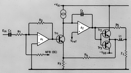
Fig.
6 shows a somewhat unusual model for further
discussion for a common used amplifier type.
To
see: two source voltages, with in each case an adjustable
output resistance. Now if a positive input signal applies
against the automatic controller (control Amp), then upper
resistance is setted to a very high impedance value, so that
only very small current can flow by the upper source. At the
same time to it from the automatic controller the lower
resistance reduced to the desired current by the loudspeaker
flows so long. More exactly said, until the desired voltage at
the output adjusts itself. For negative voltages conditions
are changed.
The
feedback line is a part of constant control (regulation)
whether two resistances were setted also correctly. And
the more precisely control happens, the more highly is the
open loop.
If
the desired voltage is zero V, then both resistances are
adjusted to the same value during same source voltage. However
to which value? Good question - until the desired idle current
of the output stage is reached.
The
transistors in the amplifier takes over the role of adjustable
internal resistances.
|
Large
amplifiers small output resistance? - small amplifier large output
resistance?
A
large hifi amplifier - that means not that dynamic internal resistance
is automatically very small. No, a very well made small amplifier can
be quite better than a less well developed large amplifier. The
substantial difference is: the small amplifier cannot follow with
rising load any longer, its dynamic output resistance rises strongly.
While with the large one only with larger load dynamic output
resistance rises somewhat.
Effects
on a bad amping factor
Keep
in mind, an indication of a damping factor is technically only
meaningfully under indication boundary condition only if for the DUT's
the damping factors are present, which were measured under similar
boundary conditions, then becomes a number comparison possible.
Effects on bad damping factor are, the output signal correspond less
to the input signal. The effects are linear
and also nonlinear
distortions.
Also
a loudspeaker can generate voltages. An amplifier with low dynamic
output resistance can compensate these disturbances better than one
with a high damping factor. Loudspeakers generate inadvertent voltages
to their connectors, similarly like the function mode of a microphone.
The amplifier must reject these. A measure for it like generated
disturbances being suppressed, is e.g. the load Rejection Ratio.
Damping factors affect the sound, loudspeaker manufacturer have
thereby experience.
A
relatively linear controlled system reduces also the effect of the
generation of nonlinear distortions. With which we concerned at the
open loop amplifier without feedback. An open loop amplifier meant,
the amplifier does not have an overall negativefeedback of the output
signal. Only individual amplifier stages using negative feedback, e.g.
through emitter resistances or through cathode resistances with a tube
amplifier.
A
feedback free amplifier works in a steered mode and not as regulation.
During directly comparable achievement of both amplifiers types, the
steered type has a higher output resistance than the regulated
amplifier. The developer of a steered only amplifier directs his
special attention to linearize his circuit. This method helps to keep
distortions low.
|
IMPEDANCE IN AUDIO TECHNOLOGY
WHEN FOUR OHMS IS NOT FOUR OHMS
There is an enclosure in our product line that we have been
making for twenty years called, the FH-1 low frequency enclosure.
We use a four ohm loudspeaker in this enclosure; however, as
long as the enclosure is operated above its cut-off frequency
of 60 Hz, the actual load impedance that the power amplifier
sees is nominally eight ohms. Likewise, we use a four ohm loudspeaker
in the Mid bass horn of HDH-4 and HDH-1 speaker enclosures.
As long as these horns are operated above their cut-off frequency
of 300 Hz, the midbass of the enclosure will exhibit an eight
ohm load to the amplifier.
The mechanical loading of the loudspeaker by the horn makes
an impedance transformation so the amplifier sees a load impedance
of 8 ohms within the horns operating bandpass. I mention the
horn's operating bandpass because if you operate any horn below
its cut-off (-3 dB down point on the low frequency portion
of its response curve), the driver reverts back to its original
lower impedance. As long as you send horn loaded enclosure
frequencies that are above the cut-off, the system will offer
a higher load impedance to the power amplifier.
The DC resistance of the loudspeakers discussed above is 3.2
to 3.8 ohms. Mounting the loudspeaker on a horn doesn't change
the DC resistance, but a power amplifier driving that horn
will see a load impedance that is more than twice that of the
nominal four ohm impedance of the individual speaker. Hopefully
some of us now understand how a four ohm loudspeaker can become
an 8 ohm loudspeaker system when mounted on a properly designed
horn.
I had mentioned earlier a situation I discovered in Africa
where a technician had a basic understanding of impedance,
but he didn't understand how horn loading can change the impedance
of a loudspeaker. We used to have a low frequency enclosure
called the FH-2. This enclosure had two four ohm loudspeakers
wired in parallel within a folded horn. Since each of the loudspeakers
was loaded by the horn, the individual loudspeakers were mechanically
raised to eight ohms. Therefore, in parallel the two equivalent
eight ohm speakers offered a four ohm load to the amplifier
when operated in its designated bandpass 60 Hz - 400 Hz.
The technician thought he was correct and that perhaps the
manufacturer had goofed. So he wired what he thought were two
four ohm loudspeakers in series, thinking that he then had
an eight ohm load for the power amplifier. However, since these
were horn-loaded speakers, he actually changed a four ohm enclosure
into a sixteen ohm enclosure. He changed them from two horn-loaded
eight ohm speakers that were mixed in parallel to two eight
ohm loudspeakers wired in series that now offered a sixteen
ohm load for his CS-800 amplifier. So instead of the CS-800
producing 400 watts into 4 ohms (200 to each speaker), it produced
only 100 Watts (50 watts to each speaker). Now not only did
he have a 6 dB loss in SPL, he totally destroyed the damping
or control capability of the power amplifier by reducing his
potential damping factor from a rating of 200 to that of 0.5.
More on Damping Factor later.
Perhaps now that you have further insight into complex impedance,
you may also agree that when misinformed people try to "out
think" the manufacturer of a loudspeaker system, they
more often than not have their own foot crushed by the wheel
that they are trying to reinvent.
I mentioned that loudspeakers should not be wired in series
for sound reinforcement applications. And it was all right
to wire them in parallel, but that they should each have their
own pair of speaker cable leads and be wired in parallel at
the output terminals of the power amplifier. This is the professional
way of wiring loudspeakers in parallel. All loudspeakers generate
a back voltage due to the motion of the voice coil within the
magnetic field of the voice coil gap. This is referred to as
a Back-EMF or backward-electro-motive-force.
Sir Issac Newton said that for every action there is an equal
and opposite reaction. If you would take a fifteen inch Black
Widow loudspeaker and hook its terminal up to the input of
an oscilloscope and slap the cone abruptly with the palm of
your hand, you could cause a voltage to be displayed on the
scope greater that 80 volts peak to peak, 40 volts peak, or
about 28 volts RMS.
If two loudspeakers are wired in parallel within an enclosure
at a distance from the power amplifier, each speaker creates
a back-EMF that causes low frequency cancellation as these
voltages are out of phase with the incoming signal. When the
two loudspeakers are wired in parallel at the output terminals
of the power amplifier, the very low internal output impedance
(source impedance) of the amplifier (typically 0.02 ohms) acts
as a shunt or near short circuit to the back-EMF voltages.
ARE YOU READY FOR MORE?
I mentioned Damping Factor earlier and I wanted to
wait until I discussed Source Impedance before I covered it
more thoroughly.
SOURCE IMPEDANCE
Up until now I have been talking about the impedances
offered by the loudspeaker load on the amplifier. The loudspeaker
load impedance is often referred to as the output impedance
of the amplifier; however, it is more correct to call this
the amplifier load impedance. This is because amplifiers have
an internal output or "source impedance."
The ratio of the source impedance to the load impedance is
the amplifier's Damping Factor rating number. The damping Factor
number can be obtained by dividing the loudspeaker load impedance
by the internal output or source impedance of the power amp.
A typical power amplifier source impedance is 0.02 ohms. If
I were to divide an 8 ohm speaker load by 0.02 ohms, I would
have a Damping Factor number of 400.
As you can see the impedance of the load affects the damping
factor of the amplifier. The same amplifier would have a damping
factor of 200 into a four ohm load (4 / 0.02 = 200).
The damping factor is the ability of the amplifier to control
the loudspeaker load. Another word for control is regulation.
The control of the load is a function of the ability of the
power amplifier's regulation of the load. If you have a precise
millivolt scale on a digital voltmeter, you can calculate the
percentage of regulation by measuring the output voltage of
the amplifier without a load (open circuit), then place the
load resistance value on the amplifiers output and measure
the voltage. It will have dropped a very small amount.
If you then take the No Load Voltage and subtract the Full
Load Voltage from it, and then divide that number by the Full
Load Voltage, you will have calculated that amplifier's percentage
of regulation. If you now take the reciprocal of that percentage
of regulation, you will have the Damping Factor rating number
of that amplifier into that load value.
NLv - FLv / FLv = % Regulation
1 / % Regulation = Damping Factor
or DF = 1 / (NLv - FLv / Flv)
Note: You can't really measure Damping Factor at full power
because that amplifier will not be able to maintain its regulation,
but as an example let's say you are measuring a CS-800X into
an eight ohm load with 6 dB of head room. Your open circuit
(NL) voltage is measured at 20 volts, you place an eight ohm
load in the circuit (you better use a dummy load or a speaker
will be awfully loud), then you measure a (FL) voltage of 19.95
volts, your math would now be:
20 - 19.95 = 0.05 / 19.95 = 0.0025
% of Regulation would be .25%
The reciprocal of 0.0025 = 1 / 0.0025 = 400
DF = 400
Source Impedance (Z source) would then be calculated from an
inversion of the previous formula for damping factor (DF =
Z Load / Z Source) would now become:
Z Load / DF = Z Source or
8 / 400 = 0.02 ohm Source Impedance
This, ladies and gentlemen is what damping factor is all about.
Remember the resistance of the load affects the amplifier's
ability to control its load. We have all heard that the professional
method of loudspeaker cable connections in audio is use to
a heavy gauge cable and the shortest possible cable run. Losses
in loudspeaker cable runs are due to the friction, or heat,
caused by the high level of electron current flow. Most manufacturers
provide an American Wire Gauge (AWG) ## 18 in a 25 foot length
as a standard loudspeaker cord. But the electrons flow back
and forth in a 50 foot circuit. The speaker wire itself opposes
current flow because it has a resistance value.
Let's use an example of an 8 ohm loudspeaker connected directly
to the output terminals of a power amplifier:

102 � 8 = 100 � 8 = 12.5 watts
Now let us suppose we are practicing very poor audio
and have a loudspeaker connected at the end of 153.6 ft of
## 18 gauge copper wire. AWG ## 18 wire has a resistance of 6.51
ohms per 1000 ft (1000 / 6.51 = 153.60), which means that 153.6
ft of ## 18 copper wire will have a resistance of 1 ohm. Since
a loudspeaker wire has two conductors, there would actually
be 2 ohms of resistance in series with an 8 ohm speaker connected
via 153.6 ft of two conductor AWG ## 18 copper wire. Now our
power amplifier looks out at the load and sees the 2 ohms of
wire resistance, in series with 8 ohm loudspeaker impedances.
So the load is now actually 10 ohms instead of 8 ohms.
 102 � 10 = 100 � 10 = 10 watts
At first glance you may say that you are only losing
2.5 watts (which is a 20 percent power loss). However, you
are actually losing 36% power. Of the 10 watts now produced
by the amplifier, 2 watts is dissipated in the wire, while
only 8 watts gets to the loudspeaker.
If you think this is not cool, let's examine what this would
do to the amplifier's ability to control or dampen the loudspeaker
load. The loudspeaker actually sees the 2 ohms of wire resistance
in series with the amplifier's internal output or source impedance.
So instead of a Damping Factor of 400, you would have:
DF = Load Z / Source Z
DF = 8 ohm / (.02 + 2 ohm) = 8 / 2.02 = 3.96 DF
We started out with a potential damping factor of 400 and because
of our poor choice of 153.6 ft of wire, we have destroyed the
amplifier's ability to dampen or control the loudspeaker load.
Can you see now why those who know, employ the professional
method of putting the power amplifier as close to the loudspeaker
system as possible and then use the heaviest gauge wire that
will fit the loudspeaker connector. If you haven't been doing
this, you need to start, as you are no longer ignorant regarding
the importance of damping factor.
Before I give up on damping factor, I would like to make one
more point. In the above example I stated that the source impedance
of a CS-800X was .02 ohms; therefore, the DF was 400 when driving
an 8 ohm load. Well, I don't usually promote products in a
paper intended to educate the customer, but I just must make
an exception. Beginning with our recently introduced power
amplifier model CS-800S, we have included circuitry (patent
applied for) that automatically maintains a high damping factor.
This is really an ingenious and simple circuit that our chief
of analog engineering, Jack Sondermeyer, came up with.
There is a circuit that measures the small change in output
voltage when the load impedance changes, and through a feedback
network, the circuitry maintains a constant output voltage
as the voltage neither increases or decreases with a change
in load impedance. You can almost think of it as a negative
source impedance so the Damping Factor remains high. It is
still affected by the resistance in the wire, so you still
would be wise to practice the professional method of short
runs and heavy duty loudspeaker wire. The CS-800S amplifiers
coming off of our production line at Peavey consistently spec
out at greater than 2000 DF, and that is only because that
is the highest number our system can measure.
WE ARE NOT DONE YET!
This paper is on Impedance, and in the course of this
paper's unfolding I segued into source impedance and used it
as a means of explaining damping factor. Source impedance also
applies when you are interfacing components within the audio
system. With loudspeakers, we are trying to match the loudspeaker
load impedance to the output of the power amplifier to obtain
maximum power. When we are only trying to transfer signal from
one device to another within the audio chain, we are not trying
to accomplish any work, so we are not trying to produce significant
levels of current. We are just trying to pass or transfer the
audio signal. There is, of course, current flow, of course,
current flow, as electrons are moving back and forth, but the
intention is to pass the signal as a voltage and not produce
high levels of current and power. However, each signal processor
in front of the power amplifier sees the input impedance of
the next device as a load on its output.
Years ago, during the Jurassic period of audio, they attempted
to transfer audio signal into 600 ohm loads. This is no longer
valid today. The typical input impedance of a modern power
amplifier is 20,000 ohm or 20 k. However, the internal output
impedance (Source Z) of audio devices can be anywhere from
50 ohms to 2,000 ohms. In order to transfer the signal without
introducing major deviations in level and frequency response,
the Source Z to Load Z should have a ratio of 10:1; some people
accept 7:1, but I hold to the 10:1 ratio.
The source impedance is often overlooked by the non-technician
sound system operator. Ignorance may be bliss, but getting
bitten on the behind is not pleasant. There are many signal
processors, equalizers, and crossovers that do an adequate
job in certain applications, but these same devices can cause
many problems when the source-to-load impedance becomes reduced.
The best and first example I am going to use is in interfacing
a number of power amplifiers in larger systems. There is a
limit to how many power amplifier inputs can be paralleled.
The limit is determined by the source impedance of the mixer
output, the equalizer, or the electronic crossover.
Using the math associated with Ohm's Law, we can calculate
what the load impedance will be when we parallel power amplifier
inputs. Two 20,000 ohm inputs in parallel becomes a 10,000
ohm load to the signal source. Dividing the input Z by the
number of amplifiers whose inputs are in parallel will give
the resultant load Z that the signal source sees. Thus ten
power amplifiers with their inputs in parallel would be 20,000
ohms divided by 10, or 2,000 ohms.
This means that if the internal output or source impedance
of the signal source were 200 ohms, we could successfully transfer
the electrical audio signal with no problems. But if the Source
Z were 330 ohms we would be below the stated 10:1 Z ratio.
In large scale professional audio it is very important to consider
the capability of products to drive long lines and/or loads
that represent multiple impedances in parallel. There are many
mixers, equalizers, and crossovers that are priced economically,
and they work fine in certain simple applications. These products
can present problems in large systems, however.
If you want to know how many power amplifiers can be driven
by a signal source, multiply the internal output impedance
of the source by 10, and divide the result into the source
impedance of the power amplifiers. For instance, in our product
line we have two series of graphic equalizers, the EQ series
and the Q series. The EQ series exhibits a 75 ohm source impedance
while the less expensive Q series has a 330 ohm source impedance.
75 x 10 = 75020,000 / 750 = 26
330 x 10 = 3,33020,000 / 3,330 = 6
You can now see that a Peavey EQ-31 can drive 26 CS amplifiers
with their inputs in parallel, while the Q series could only
drive 6. Thus, in applications such as small systems, the Q
series could do a fine job, but there is a limit and now you
know the boundaries.
I know of one mixer manufacturer that has a source impedance
in their mixer's channel inserts of 1,000 ohms. This is not
a real problem if you come out of the mixer with a five to
eight foot shielded signal patch cable to interface some processor.
But there are many users of this product that have them in
studios where the inserts are permanently wired through lengthy
cable that is run beneath the floor across the studio to a
patch bay. They don't realize that the mixer channel is now
rolling off the high frequencies significantly because of the
capacitance of the cables and the high source impedance.
The cable itself becomes a low pass filter. The amount of high
frequency roll-off is determined by the value of the source
impedance. You can find the point where the frequency begins
to roll off by taking reciprocal (1/X) of the source impedance
(R) times the capacitance (C) in the cables, 1 / (R x C). Let's
say, for example, that the cable is long enough to offer 0.2
mfd of capacitance (a microfarad is mathematically 0.000,001
farad).
1 / 100 x 0.000,000,2 = 1 / 0.000,02 = 50,000 Hz or 50 kHz
1 / 1,000 x 0.000,000,2 = 1 / 0.000,2 = 5,000 Hz
The signal processor hooked up to the mixer with an insert
with a 100 ohm source impedance would pass signals out to 50
kHz, while the mixer with the 1,000 ohm source impedance in
its insert would have significant roll-off above 5 kHz.
We have come to the end of this lengthy paper on Impedance.
I believe we have pretty much thoroughly covered the subject.
Some of the things I just shared with you took me fifteen years
or more to understand as I now do. I don't know about you,
but I am still learning. If you are learning, you are growing.
When you stop growing you cease to produce quality.
Below, you�ll find a chart relating source-to-load impedances
and the number of amplifiers that can be driven with the inputs
wired in parallel. There is also a chart on loudspeaker wire.
| SOURCE
Z |
LOAD
IMPEDANCE |
| (in ohms) |
1 K ohm |
2 K ohm |
10 K ohm |
20 K ohm |
| 75 |
1 |
2 |
13 |
26 |
| 100 |
1 |
2 |
10 |
20 |
| 330 |
0 |
0 |
3 |
6 |
| 1000 |
0 |
0 |
1 |
2 |
| 2000 |
0 |
0 |
0 |
1 |
| Copper
Wire Guage |
| AWG## |
Dia
mils |
Dia
mm |
Cir
mils |
Square
inches |
Sq
mm |
Meter/
ohm |
Feet/
ohm |
Audio
amps |
Max
pwr |
Length
DF<50 |
| 22 |
25.35 |
0.6438 |
642.4 |
0.000504 |
0.33 |
18.52 |
60.75 |
3 |
|
|
| 18 |
40.30 |
1.024 |
1624 |
0.001276 |
0.82 |
46.8 |
153.6 |
5 |
150W |
10 Ft |
| 16 |
50.82 |
1.291 |
2583 |
0.002028 |
1.31 |
74.47 |
244.26 |
7 |
280W |
15 Ft |
| 14 |
64.08 |
1.628 |
4107 |
0.003226 |
2.08 |
118.4 |
388.35 |
9 |
400W |
25 Ft |
| 12 |
80.81 |
2.053 |
6530 |
0.005129 |
3.31 |
188.3 |
617.7 |
12 |
800W |
40 Ft |
| 0 |
101.9 |
2.588 |
10380 |
0.008155 |
5.26 |


 | | | | | | | | | | | | | | | | | | | | | | | | | | | | | |


Tidak ada komentar:
Posting Komentar