Satellite Earth Stations


Working Principle Satellite Communications
The stages in the workings of the satellite is divided into three stages, namely, the first phase of the satellite receives a signal which is then in the second stage will enlarge the satellite signals. Then at the last stage, the signal is returned to Earth and received by several stations on earth. As seen in the figure below.


X . I
What is a Satellite?
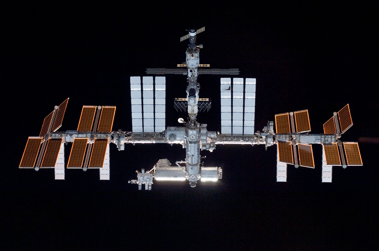

The International Space
Station is the largest satellite in orbit. This file photo of the
station was taken in May 2010 by NASA space shuttle astronauts.
Credit: NASA
There are dozens upon dozens of natural satellites in the solar system, with almost every planet having at least one moon. Saturn, for example, has at least 53 natural satellites, and one artificial one — the Cassini spacecraft, which is exploring the ringed planet and its moons.
Artificial satellites, however, did not become a reality until the mid-20th century. The first artificial satellite was Sputnik, a Russian beach-ball-size space probe that lifted off on Oct. 4, 1957. That act shocked much of the western world, as it was believed the Soviets did not have the capability to send satellites into space.
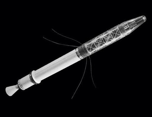

Explorer 1 was the first U.S. satellite and the first satellite to carry scientific instruments.
Credit: NASA/Jet Propulsion Laboratory
A brief history of satellites
Following that feat, on Nov. 3, 1957 the Soviets launched an even more massive satellite — Sputnik 2 — which carried a dog, Laika. The United States made several unsuccessful attempts to send its own satellites into space before succeeding with Explorer 1 on Jan. 31, 1958. The satellite was only 2 percent the mass of Sputnik 2, however, at 30 pounds (13 kg).The Sputniks and Explorer 1 became the opening shots in a space race between the United States and the Soviet Union that lasted until at least the late 1960s. The focus on satellites began to give way to people as both countries sent humans into space in 1961. Later in the decade, however, the aims of both countries began to split. While the United States went on to land people on the moon and create the space shuttle, the Soviet Union constructed the world's first space station, Salyut 1, which launched in 1971. (Other stations followed, such as the United States' Skylab and the Soviet Union's Mir.)
Other countries began to send their own satellites into space as the benefits rippled through society. Weather satellites were able to improve the forecast, even for remote areas. Land-watching satellites such as the Landsat series tracked changes in forests, water and other parts of Earth's surface over time. Telecommunications satellites made long-distance telephone calls and eventually, live television broadcasts from across the world a normal part of life.
With the miniaturization of computers and other hardware, it's now possible to send up much smaller satellites that can do science, telecommunications or other functions in orbit. It's common now for companies and universities to create "CubeSats", or cube-shaped satellites that frequently populate low-Earth orbit. These can be lofted on a rocket along with a bigger payload, or sent from a mobile launcher on the International Space Station (ISS).
The ISS is the biggest satellite in orbit, and took over a decade to construct. Piece by piece, 15 nations contributed financial and physical infrastructure to the orbiting complex, which was put together between 1998 and 2011. Program officials expect the ISS to keep running until at least 2024.
Parts of a satellite
Every usable satellite — whether it's a human or robotic one — has four main parts to it: a power system (which could be solar or nuclear, for example), a way to control its attitude, an antenna to transmit and receive information, and a payload to collect information (such as a camera or particle detector).As will be seen below, however, not all artificial satellites are necessarily workable ones. Even a screw or a bit of paint is considered an "artificial" satellite, even though these are missing these parts.
What keeps a satellite from falling to Earth?
A satellite is best understood as a projectile, or an object that has only one force acting on it — gravity. Technically speaking, anything that crosses the Karman Line at an altitude of 100 kilometers (62 miles) is considered in space. However, a satellite needs to be going fast — at least 8 km (5 miles) a second — to stop from falling back down to Earth immediately.If a satellite is traveling fast enough, it will perpetually "fall" toward Earth, but the Earth's curvature means that the satellite will fall around our planet instead of crashing back on the surface. Satellites that travel closer to Earth are at risk of falling because the drag of atmospheric molecules will slow the satellites down. Those that orbit farther away from Earth have fewer molecules to contend with.
There are several accepted "zones" of orbits around the Earth. One is called low-Earth-orbit, which extends from about 160 to 2,000 km (about 100 to 1,250 miles). This is the zone where the ISS orbits and where the space shuttle used to do its work. In fact, all human missions except for the Apollo flights to the moon took place in this zone. Most satellites also work in this zone.
Geostationary orbit is the best spot for communications satellites to use, however. This is a zone above Earth's equator at an altitude of 35,786 km (22,236 mi). At this altitude, the rate of "fall" around the Earth is about the same as Earth's rotation. (From the ground, the satellite would appear to be still.) This allows a satellite to perpetually keep a connection with a fixed antenna on the ground, allowing for reliable communications.
While some satellites are best used around the equator, others are better suited to more polar orbits — those that circle the Earth so that the north and south poles appear underneath them. Examples of polar-orbiting satellites include weather satellites and reconnaissance satellites.
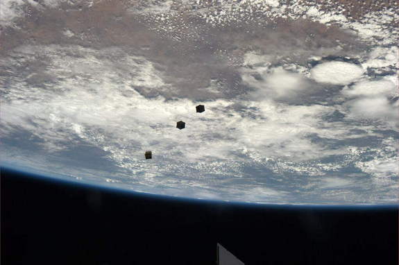
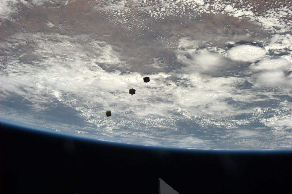
Three small CubeSats float
above the Earth after deployment from the International Space Station.
Astronaut Rick Mastracchio tweeted the photo from the station on Nov.
19, 2013.
Credit: Rick Mastracchio (via Twitter as @AstroRM)
What stops a satellite from crashing into another satellite?
There are an estimated half-million artificial objects in Earth orbit today, ranging in size from paint flecks up to full-fledged satellites — each traveling at speeds of thousands of miles an hour. Only a fraction of these satellites are useable, meaning that there is a lot of "space junk" floating around out there. With every thing that is lobbed into orbit, the chance of a collision increases.Space agencies have to consider orbital trajectories carefully when launching something into space. Agencies such as the United States Space Surveillance Network keep an eye on orbital debris from the ground, and alert NASA and other entities if an errant piece is in danger of hitting something vital. This means that from time to time, the ISS needs to perform evasive maneuvers to get out of the way.
Collisions still occur, however. One of the biggest culprits of space debris these days is the leftovers of a 2007 anti-satellite test performed by the Chinese, which generated debris that destroyed a Russian satellite in 2013. Also that year, the Iridium 33 and Cosmos 2251 satellites smashed into each other, generating a cloud of debris.
NASA, the European Space Agency and many other entities are considering measures to reduce the amount of orbital debris. Some suggest bringing down dead satellites in some way, perhaps using a net or air bursts to disturb the debris from its orbit and bring it closer to Earth. Others are thinking about refueling dead satellites for reuse, a technology that has been demonstrated robotically on the ISS.

X . II
For telecommunication technology and activities SATELLITE COMMUNICATION SYSTEMS
"Satellite" we often hear about the words of the satellite, but do we understand
whether in fact that satellite. In the images below will be explained about the architecture of satellite communications.

segmen angkasa = the space segment
Figure 1. Architecture satellite communicationsIn the picture above satellite communications architecture consists of two segments, namely:The space segment and the earth segment. The space segment consists of (bus, Payload,Power Supply, temperature control, attitude and orbit control system population,Telemetry Tracking and Command TTC). As with other electronic equipment systemsSatellite also require a power supply usually solar powered. elements of the systemthe specifics of the satellite is the attitude and orbit control, as well as the TTC, this controlvery unusual because it can control the earth from space. And the person who made it can be said lunatic how they are not able to map the earth-inch-by-inch in the magnitude of the numbers called lattitude and longitude. This attitude and standards used by all American-made satellites. Thought what if we make or map the earth in the longitude and latitude coordinates its own distinct with the Americans and we make their own equipment can also translate coordinates attitude "different" before such dab GPS satellites of its own so that the enemy does not know. While on Earth Segment satellite communications architecture consists of user terminals, the Earth segment, and the network master. As mobile communication systems segment could be called a mobile earth station is.
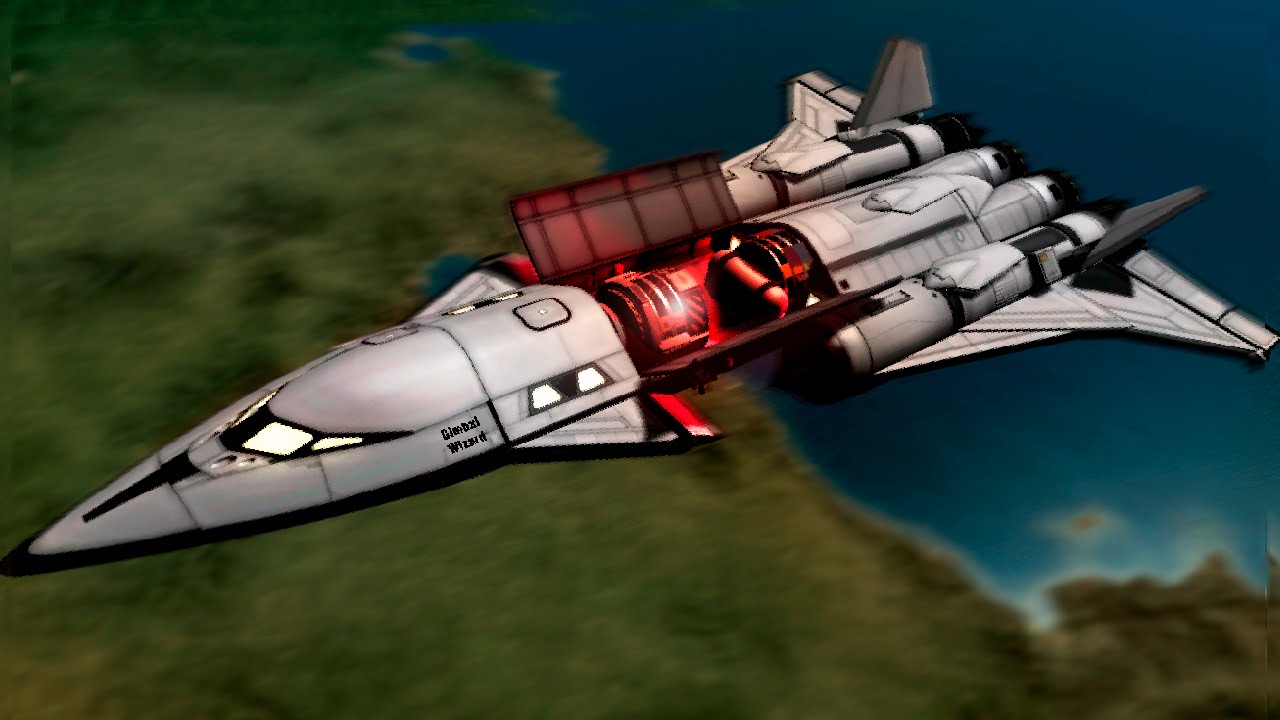
There are many forms of satellites, satellite shape depending on the raft or his spaceraft in the image below examples show spaceraft .

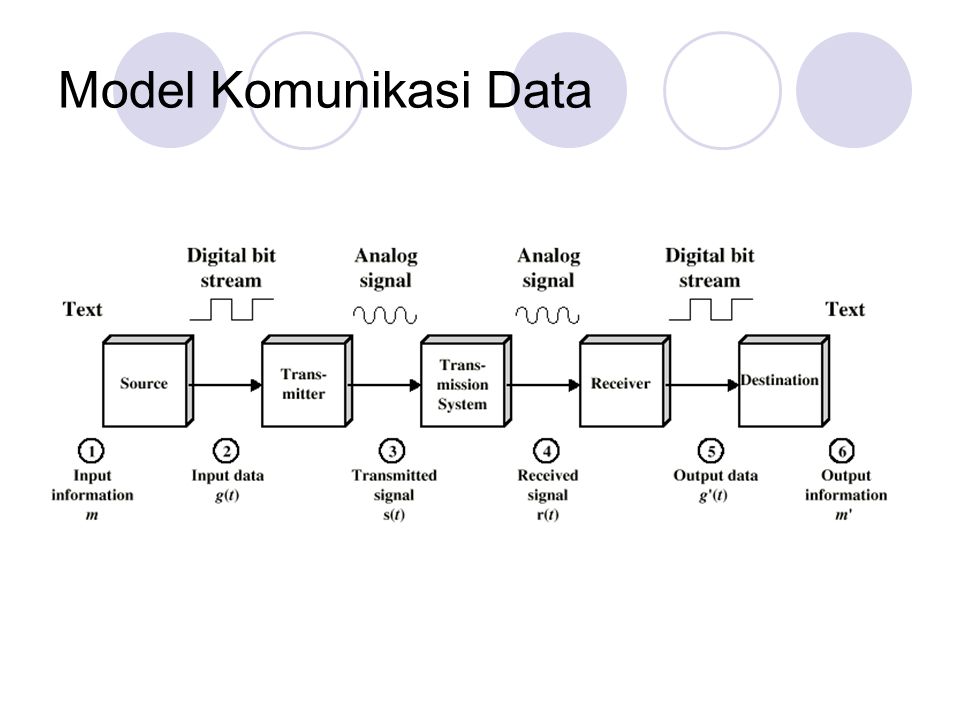
Figure 2. Raft Space
While the blocks of electronic circuits that make up the satellite communication architecture can be seen in the picture below. As communication Duplex (two-way) link or other communication path consists of a transmitter and receiver.
 Figure 3. The basic components of a satellite link
The main component of the satellite is its antennae for satellite antenna will affect the coverage area can be served by the satellite. Although located in space and hovering satellites up there could still cover the area of the earth at the same place because the satellite was placed in orbit and a certain height from the surface of the earth. We should thumbs-up to the inventor of this natural wonder, and could use it. The types of orbits can be seen in the picture below.

Figure 4. Type Orbit
Delay or time delay that occurs in the relationship between the sender and the receiver in this case satellite communications systems and cordless clearly an important parameter that determines the performance of the communication link. While the orbital period will determine the type of satellite communications and also constellation design communication coverage. In the picture below AKN describes the various delay
inversely with distance.

Figure 5. Comparison of satellite communication delay
While the placement of the satellite constellation or satellite area is also another important factor in the satellite communications system. For global coverage customarily required when more satellites are placed in several areas of satellite orbit and the space between is determined. Idea of what it could be seen in the image below.

Figure 6. Constellation Satellites
Form of coverage (beam) satellites there are three forms, each of which depends on an antenna that shape it. There is a global shape, spot and shaped.

Figure 7. Shape satellite coverage
In satellite communications regulation mainly GEO orbital slots and frequency internationally have been carried out by ITU-R. Because each country has the right to claim the airspace (space) above, it must be coordinated for the filling
orbit and frequency allocation so that no overlapping and interferences .
The satellite has a variety of uses. The following will explain about the usefulness of the satellite. The first to telephone and data services, dial-up voice, fax and data in the multiplex and processed (compressed) before it is inputted to a satellite modem. Example diagram of how it works can be seen in the picture below.
 Another function is to Direct Broadcasting Services (direct broadcast services) which is used for cable TV for example.
Satellite functions as described above are for:
1. The distribution of point -to - multi point TV program from the studio to the local broadcast station
2. The transmission of point-to-point broadcast coverage directly to the studio
3. Distribution of point - to - multi point cable TV programs from studios to local TV cable
4. Distribution of point-to-multi point cable TV programs and / or TV networks directly from the studio to the customer.
While the other functions of the satellites for instance for V S A T (very small aperture terminal)
V S A T is a mini system of satellite communication systems are usually the coverage in a province or an island alone.

Figure 10. VSAT Network
Examples of devices for broadband communications VSAT can be seen in the picture below.

The advantages of satellite communications include:
1. Scope comprehensive: one country, region or continent.
2. Bandwidth provided sufficient width.
3. Independent from terrestrial infrastructure.
4. Installing the network segment of the earth fast.
5. Relatively low cost per site.
6. Service uniform and it's currently only one provider.
7. mobile services / independent wireless in everywhere well.
While the weakness:
1. High Cost Up Front: Example for GEO Satellites: Spacecraft,
Ground Segment & Launch = US $ 200 Million, Insurance: $ 50M.
2. Distance insensitive: Fees for short-range communication and far are relatively similar.
3. The only economical if a large number of users and the capacity used intensively.
4. Propagation delay is great.
5. Susceptible to influence atmosfir , etc.
X . III
basic foundation of the satellite communication system
In the current era of globalization, the flow of information exchange is very high. Communication needs to be accompanied by the development of a reliable telecommunications network. It is necessary for the transmission media that carry information such as voice, image and data communication, or a combination of them.
The use of satellites is one of the effective and appropriate way for us, considering the geographical conditions in the earth that consists of thousands of islands and has a very wide area. In seeking to build a telecommunications infrastructure that can reach all the activities on earth, but used a network of microwave, submarine cable, and optical networks, the use of satellite networks can simultaneously reach all areas of the earth.
"The satellite is an object that circulate in space and around the Earth, serves as a radio station that receives and transmits or re transmits and or receive, process and re transmit radio communications signals".
From that sense, it can be concluded that it is essentially a repeater satellites contained in space, where its function is to capture the signal from the earth and then resubmitted. However, to maintain the transmitted signal needs to be held back in revamping the received signal. The received signal must have weakened (attenuation) and disability (distortion) on the way from the Earth to the satellite. The reconstruction process is done so that the signal to be transmitted back to Earth, such as or close to the original signal.
Satellite communication systems utilizing microwave system that works at frequencies above 1 GHz, where the properties of wave propagation in general follows the propagation properties of light that Line of Sight ( L o S) or propagate in a straight line. Microwave systems can be used in terrestrial systems (vines follow the earth's surface) as well as satellite systems. Since 1950 microwave system has become the primary choice as a carrier of information over long distances.
The characteristic properties of microwaves are as follows:
Straight propagation direction (Line of Sight), which require free space without barriers in their propagation in the air.
Optical properties, so that it can be affected by water vapor, precipitation and refraction by air.
Requires RF transmit power that is not too big and efficient, with the use of an antenna which has a strengthening briefing (directivity) high.
Has a high frequency, thus providing bandwidth (bandwidth) transimision very wide and reliable to transmit thousands of telephone channels as well as having the same quality if used for multiple channel television and data communication channels.
Frequency (carrier) used is in the range of 3-12 GHz.
Characteristics of Radio Waves
From a wide range of communication techniques which are known, may be one that is very sensitive to changes in the radio wave radiation. The basic principle is that allows propagation of radio waves can be up to outer space is currently the same as that performed 100 years ago. Thorough understanding of this principle is fairly easy, although some people consider radio wave propagation complex and confusing, it is true because it is the invisible force that is not perceived bias and bias are not touched. It depends on the individual imagination to visualize the sequence of concepts and their relation to the application exercises.
The arrival of wireless Marconi in 1895 to make the transmission of information can be carried on radio waves. Wave propagation reachable location signal reception also affect the strength of the field. There are three major classifications for the propagation of signals or wave : Waves of land, space waves, and airwaves.
The concept of radiation from radio waves can be visualized by dropping a pebble into a pool of water. When gravel falling to nature the water, surface disturbance occurs, causing the water to move up and down. At this point in the transmission disturbance to the surface of the pool in the form of circular waves expanding. It may be noted that the water does not move away from that point. For small leaves or wood placed on the surface of the pond, there will be no movement, but only movement Keats and down for each wave passes. Kinds of waves generated by the water called transverse wave, a wave that occurs in the direction or directions are perpendicular on the direction of wave propagation. Simple wave called wave. Electromagnetic waves in the transmission by the antenna is an example for a wave.
The basic shape of the carrier wave (carrier) generated by the transmitter in the form of a sine wave. Transverse waves radiated into space, however, that may A A U can not maintain the characteristics of a sine wave, depending on the type of modulation of the carrier.
Frequency
Frequency (f) of a wave is the number of cycles of a sine wave that occur in one second. Such as radio waves, the frequency can be interpreted as the number of cycles of a wave that passes at one given point in one second. For example, Figure 1 shows two pieces of the cycle occurs in one second, therefore, a sine wave is said to have two cycles per second.
In 1967, in honor of the German physicist Heinrich Hertz Hertz its mean has been designated for use as a replacement cycles per second term when referring to the frequency of the radio wave. May seem confusing that one spot in terms of cycles used to replace the positive and negative alternative of a wave, but in another incident Hertz terms used to replace what seems like the same thing. The key is the time factor, the cycle refers to any sequence of events, while hertz refers to the many events that took place one second.
Hertz abbreviated Hz, is equal to one thousand Hertz kHz, now usable frequency range extends from about 15 Hz to about 300 GHz.

Basic Characteristics Sine Wave Pictures
In the world of broadcasting frequencies used two classifications, namely the audio frequencies and radio frequencies. The frequency of the audio frequency is the frequency which has a range between about 15 Hz and 20 kHz. These frequencies the human ear can hear and including all voices be heard regularly every day. For example, the average frequency of speech sounds that can be heard around 128 Hz, however, the singing of soprano rate may reach 1300 Hz. Proportional extremely high sound of musical instruments and whistling adjacent, reaching the limit of the range AF. Meanwhile, the frequency of which fall to be between 3 kHz to 300 GHz is called the Radio Frequency (RF) which is commonly used in radio communications.
Period
The period of radio waves is the amount of time it takes to complete one cycle. For example, Figure 1 has a frequency of 2 Hz, therefore each cycle has a duration or time of half a second. If the frequency of 10 Hz, the period of each cycle is one per ten seconds. Since the frequency of radio waves is the number of cycles that can be completed in one second, it can be seen the greater the frequency, the period will be smaller.
Satellite
Since 1920 until early 1960, long-distance communication is still using the HF band propagation. And so many users still increase every year, HF band quickly became congested, and the frequency of smoking be paid. although the communication needs of the world have encountered in the past, large-scale improvement to be made to the satisfaction and future needs. Communication satellites are purely external growth of forwarding the demand for larger capacity, high quality komnikasi.
The earth is literally surrounded by artificial satellites. Many of these satellites carry repeaters and used for communication. In recent years, satellite has been placed in synchronous orbit, providing the capability development of communication between almost all pony-points as possible over the globe. Although we think this situation inherited now, such communication is not possible when the beginning of 1960
Satellite communications oldest, is the moon. Moon is a reflector of radio waves are pretty good and have been used for long distance communication, particularly by radio amateurs. Unfortunately this is a communications satellite that is troublesome, because it is above the horizon only half-time and move across the sky.
In about 1960, a series of passive satellite was launched into orbit around the Earth. These tools, called satellites echo, like a balloon iron which reflect waves - radio waves are transmitted. These satellites placed in low orbit, because we do not have the technology at that time to put a satellite in synchronous orbit. Area coverage of satellite echo is limited to low orbit and access a short time.
Satellite active communications satellite was made after the echo. An active communications satellite is a repeater orbit with broadband characteristics. A signal received from the earth station is received, converted to another frequency and transmits back as the power level being. This arrangement provides better signal strength on the receive at the end of the circuit, when compared to the passive satellite. The first active satellites placed in low orbit. and so their users have been plagued by the same deficiency when the satellite is found echo. Finally, active satellite placed in synchronous orbit, making it possible to use satellites with a fixed antenna, with a moderate level of power transmission, and anytime of day or night.
Now, a lot of synchronous satellites in orbit on our planet which is causing an suluit to find space to add. Almost everyone equally requires synchronous satellite. Satellite is used for TV and radio broadcasting, and military operations.
Vision Arthur C. Clarke
Satellites are the first man-made orbiting at an altitude of several hundred kilometers away from the surface of the earth with an orbital period of only 1-2 hours. Now geostationary satellites have been used extensively with an orbital period of 24 hours, the same as the time it takes the earth to rotate.

The concept of the geostationary orbit theory proposed by Arthur C. Clarke in an article in Wireless World magazine edition in October 1945, "All telecommunications constraints can be solved by placing a few pieces of repeater stations (satellites) in space with a rotation period of 24 hours a day at an altitude of 42,000 km from the center of the earth ". In this theory mentioned that to cover the entire surface of the earth it takes at least three satellites, each of which is 120o to each other. Arthur Clarke's vision is illustrated in Figure 2.
orbit satellites
According trajectory, satellite grouped into 3 types:
1. Orbit equatorial / equatorial.
Is located on the trajectory orbit the equator. The orbital plane of cutting the equatorial plane with 36,000 km distance to earth. Satellites located at this orbital speed equal to the speed of rotation of the earth, and therefore this orbit is called geostationary orbit. Because it has the same speed as the movement of the Earth, the satellite communications on Earth could serve as long as 24 hours without stopping. Equatorial orbit is shown in Figure 3.
2. polar orbit.
Is located on the trajectory orbit the poles of the earth. Orbit is able to reach the entire surface of the Earth around the poles of the earth, and therefore this orbit used by satellites for purposes of scientific research, military and limited communication.

Figure 3. Equator and Polar Orbit
3. Intermediate Orbit
Orbit is at an angle to the equator. The angle that is commonly used is 63o to the equator. For one rotation takes 12 hours. For the purposes of constant orbit communication system is certainly less reliable because it can only serve the communication system for 12 hours each day. To establish continuous communication takes at least three satellites. This intermediate orbit system used by Russia which has a lot of research stations and the military in the north polar region and the Arctic Ocean. The distance is not always the same orbit point towards the Earth, the closest point called perigee being the farthest point is called apogee, as shown in Figure 4.

Figure 4. Distance Satellite to the Earth
Satellite Frequency Band
About 55 years ago, radio communication technology is already highly developed. However, there are still many technical difficulties in producing the active components are necessary because at that time undiscovered Solid State Device. The active components include electronic tubes for amplifier / oscillator / mixer, it led to the use and utilization of the radio frequency spectrum is still very limited.
At times it was common RF spectrum split into three groups, namely, the areas L F (Low Frequency), M F (Medium Frequency) and HF (High Frequency), which reached 30 MHz. Everything beyond that is considered quite severe and was listed on VHF (Very High Frequency).
Relationships frequency (Hz, kHz, MHz, GHz) and radio wavelengths (meters) are:

where: f = frequency (MHz), λ = wavelength of the radiation (m)
It is understandable, formerly they were operating at a wavelength of about 1500 meters, then medium, about 300 meters away, and a short between 11 to 100 meters.
After the second world war, many research results that were once secret, is used for the advancement of the electronics industry that began to develop the technology area VHF reach 250s MHz, which is the equivalent wavelength of about 1.2 meters. In fact, around the '60s have been creeping up until close to 1000 MHz / 1 GHz which wavelength is approximately 0.3 meters. Regional frequencies above 300 MHz are classified as UHF (Ultra High Frequency). If the area continues to 3000 MHz, the wave length of 0.1 meters, then when around 10 GHz, the wavelength of 0.03 meters.
As well as the classification of wavelengths and then started to run out naming began long wave, medium wave, short wave and continue to micro-wave which is a term for all wave length less than 50 cm. Over time, the provisions above is growing so that when a statute is as shown in table 1 and 2.
Table 2 shows the distribution of the microwave band for communications used in satellite communications and terrestrial communications. The division of this band is the recommendation of the CCITT (Consultative Committee for International Telephone & Telegraph).
Satellites now have a solution to the limitations of global communication that had been inaccessible by conventional communication systems that already exist. Currently there are hundreds in earth orbit satellite that serves to relay the signal, good communication signals, television signals and other signals in accordance with the type of satellites.
Frequency signals used in satellite and terrestrial communications are in the order of Giga Hertz (GHz), as shown in Figure 5 below.

Figure 5. Frequency Electromagnetic Spectrum.
To relay the signal from the earth station, the satellite must have a line of sight microwave up link and to reproduce accurately the same signal to be no point microwave down link. To prevent interference between the two, the up link frequency to be emitted at a frequency higher than down link frequencies. Electronic devices which connect the signal on the satellite up link and down link is called a transponder. Transponder serves as a translator repeated (repeated-translator) with a specific reinforcement, depending on the area covered and the draft acceptance. The signals transmitted to the satellite communications in general (C-band) between 4-6 GHz or belong to a group Super high Frequency (SHF).
At this time the satellite service to keep working on C-band frequency that is uplink 6 GHz and down link 4 GHz, as well as the broadcasting system directly or Direct Broadcasting System (DBS) since 1985 is set at Ku-band frequencies which up link 17 GHz and down link 12 GHz.
The radiation of radio frequency (RF) up to about 25 MHz (short wave around 13m) can still be reflected by the ionosphere layer, which is located at an altitude of between 200-300km from Earth, used for SSB Radio communication distance (250 km up to thousands of km).
Higher frequency bands such as HF (2 MHz-30 MHz), could no longer be used for remote communication. When higher frequencies up to 800 MHz, then a layer of troposphere will be more involved in the utilization of telecommunications over the horizon (medium-range) on a system-Tropo Scatter Radio.
Communications satellites use frequencies ranging around 1.3 GHz (L-Band, C-Band and Ku-Band). These frequencies are used for the waves with the frequency is not affected by the Troposphere and Ionosphere on the Earth's atmosphere so that the waves from the ground station can be up to a satellite and a wave from the satellite can be up anyway to a ground station properly.
footprint
Footprint is the coverage area of the satellite in the Earth's surface. Footprint is also called terrestrial area are designed so that the shape of the desired region. The whole earth station can receive the satellite signal if it is in footprint area. The stronger the signal emitted, the better the earth terminal in receiving it.
Strong signal which is emitted by the satellite could be very weak when received at Earth due to various factors. At high frequencies, the path loss will increase by the square of the frequency and the square of the distance. The weather was also very influential factor, which not only rain can dampen the signal, but also lower the temperature, causing the losses caused by movements of molecules that increase the noise (noise).

Figure 6. Satellite Footprint
Methods Multiple Access
There are three methods used for up link and down link transmission, ie Frequency Division Multiple acsess (FDMA), Time Division Multiple acsess (FDMA) and Code Division Multiple Access (CDMA). There are also Demand Assignment Multiple Access (DAMA), but multiple access is rarely applied.
1. Frequency Division Multiple Access (FDMA)

FDMA System Concepts
FDMA is also called frequency division multiple access, is a multiple access system in which the entire frequency band of the satellite is divided into several narrower frequency bands, where each earth station in the FDMA system is ranked as one of the frequency band.
In FDMA systems, each earth station is served by the satellite has a different transmit frequencies between the earth stations with other earth stations. In figure 7 it can be seen that each earth station transmit and receive signals with different frequencies, namely F1, F2 and F3. In the figure 8 pattern shown FDMA in the frequency domain with time.

transmitted base receiver base
Figure 8. FDMA in the Frequency Domain Time
In the implementation, there are two techniques FDMA operation, namely:
Chanel Multi-per-Carrier (MCPC), where the earth station transmits multiple single side band carrier tape carrier channel information into a baseband carrier frequency modulate an RF carrier assembly and transmitted to a satellite transponder FDMA. In MCPC systems, each station on the earth will radiate RF carrier frequency is fixed and different from the other earth station, so that the earth station will receive signals in accordance with the desired RF carrier is used by using an appropriate band pass filter.
Single Channel per Carrier (SCPC), wherein each channel information freely modulate the RF carrier portion and transmitted to the satellite transponder FDMA. Can be analog modulation such as Frequency Modulation (FM) or digital modulation such as Phase Shift Keying (PSK). Each earth station in the system can radiate at a certain frequency at the same time. Advantages of signal transmission of information to the SCPC mode is as follows:
The new carrier wave signal is used when there is information (modulation), so do savings and the canal and power efficiency for transmitting signals to the satellite.
Have a high degree of flexibility to the expansion of communication networks.
Crockery relatively economical.
Able to be used on any size of bandwidth (up to one transponder bandwidth)
While the weakness SCPC include:
Require on-site control
When used in remote areas, the antenna must be protected
Antenna SCPC bandwidth is shifted to disturb other users can be fined up to $ 1100 per minute (effective from 2003)
Inefficient when used on a bursty transmission
2. Time Division Multiple Access (TDMA)
TDMA is a multiple access types that implement time division (time-sharing) for setting signals delivered from multiple earth stations in the occupied satellite transponder.
In the TDMA system, ground stations emit a burst-burst signal containing information that has been modulated on time slots (time slots) specified in turns so that an earth station differentiated into time slots occupied. Yet despite its different time slot all the earth stations have the same transmission frequency.

earth station
Figure 9. Concept TDMA Systems
In figure 9 it can be seen that each earth station emits a signal to the satellite with the same frequency, but at a different time slot. The width of each time slot earth station should not be the same but it depends on the number of channels to be transmiting . For stations with the number of channels much needed time slot that is wider than the earth station with fewer channels.

Figure 10. Configuring TDMA Frame
In Figure 10 TDMA frame configuration can be burst-burst turns occupying the earth station satellite transponder in time. The length of time the occupation vary from burst to burst more depending on the size capacity of the signal to be transmitted.
Between burst granted certain intervals called guard band (guard band) which serves to prevent signal interference between bursts. While synchronizing the burst refference. Each burst of each earth station is composed of several sub-burst. Due to the TDMA system there is only one frequency beam, the satellite transponder will only be burdened by the frequency of the carrier so as to avoid inter modulation interference frequencies.
3. Code Division Multiple Access (CDMA)
In the CDMA system, the signal is transmitted dispersed through part or all of the transponder bandwidth that can be used in relation frequency - time with the transformation code. Just as in the TDMA system, each earth station has the same working frequency
all earth stations simultaneously transmit their signals in a format code.
3. Space (Space Segment)
Equipment in a satellite communication system, generally grouped into two categories, namely as a satellite space segment (space segment) and earth stations as a segment of the earth (ground segment). Space segment only has a single device that is the satellite.
Satellite communication is nothing other than a communications repeater (repeater) in space. The signals transmitted by the antenna earth station antenna is received by satellite and then sent back to earth after the signal is amplified. Given the very high investment costs, the satellite must be designed so as to have the life (life time) long and can work with high efficiency.
The lifetime of a satellite communication is generally determined by several factors, namely:
Fuel capacity available.
Age of the battery (solar array power output)
The number of transponders available.
The durability of the electronic equipment on the transponder

Figure 11. Types of Satellites (a) Spin Axis, (b) Three Axis
Satellites have stabilized limiting movement by movement of rotation (spin-stabilized) or by three axes (three-axis stabilized motion restriction) with batteries Nickel Cadmium (Ni-Cad) reloadable. These batteries are also used to keep alive the satellite during the solar eclipse which occurs twice a year. In figure 11 are shown several types of Spin Axis satellite Stabilization and Three Axis Stabilization.
3.1 Compiler Satellite Subsystems
To be able to perform their duties, then a satellite requires equipment or subsystems are antennas, electric power generation (power generator), system command, telemetry and tracking (TT & C), propulsion (thrust) and stabilization system.

Figure 12. Compiler Satellite Subsystems Axis Spin mode
1. Satellite Antenna
Antenna function to receive simultaneously emit a signal. The output signal at the antenna is passed in a diplexer to separate the signals transmitted and received. Also installed a filter designed carefully to prevent the leaking of the transmit signal to the receiver.

2. Transponder Subsystem
Transponder is a series of electronic equipment that serves to receive, amplify and change the frequency of the received signals to be transmitted back to Earth. The amount of the capacity of a satellite transponder is determined by the amount owned by the satellite. Each transponder has a predetermined frequency range. The greater the bandwidth that can be served by satellite, means more transponders that can be owned by the satellite.

Figure 14. Satellite Transponder System
In figure 14 it can be seen that the electronic devices in the satellite consists of LNA (Low Noise Amplifier), mixer, oscillator, Band Pass Filter (BPF) and Low Power Amplifier form of TWT (Travelling Wave Tube). The up link signal from the earth station antenna is received by a satellite receiver. Signal is filtered to pass the required signal only. Once filtered, the signal is passed to the LNA to amplify the power level of the signal to be processed. Microwave osilator generates a signal to and processed in the mixer together with the information signal from the LNA. The output signal from the mixer is the signal summation, subtraction, a signal of LNA and signal from the oscillator. The entire output signal is passed to the BPF Mixer to pass the signal reduction, so we get signal 4 GHz. The output of the BPF is then reinforced by the strengthening of the TWT for later in propagation to Earth as a down link signal.
3. Power Subsystem Power (Electrical Power)
Serves to generate electric power required satellite. This includes equipment to set and change the power in accordance with the level of voltage / power required by each device. Electric power required by the satellite is obtained by a solar cell array that converts the sun's heat energy into electrical energy.
4. Subsystem Command and Telemetry (Command and Telemetry)
Serves to receive commands (command) transmitted by an earth station controller and transmits data about the condition of the satellite to the earth. Satellite is controlled by the SPU (master control station).
5. Push Subsystem (Thrust)
Serves to regulate changes in position and elevation satellites to remain at the place specified in the geostationary orbit. Propulsion systems are controlled remotely (remote) from the earth station main controller.
6. Stabilization Subsystem (Stabilization)
Serves to keep the satellite antenna can always lead to the appropriate target on the surface of the earth. Stabilization function performed by a SPU with surgery satellite tracking (tracking).
3.2 Types of Satellites
Based on its orbit, satellites are classified into 3 groups:
1. Satellite System Disorders (Random Satellite System)
This system is also called "Satellite system Not Controlled", ie with the launch of several satellites at different orbital altitudes ranging from hundreds of km to 10,000 km.
Movement of these satellites will be followed by two earth stations that can see each other and with each other using the displacement method (switching) between the two antennas which can rotate at each station, will be reduced when broken relationship. Mechanisms tracking (tracking) on this system is difficult. The advantage of this system is the ease of launching satellites and satellite signals received strong field at the earth station.
2. Gradual Satellite System (Satellite Phased System)
The system consists of various types of orbits, such as the Equator Orbit, Orbit at an inclination angle of 30o, polar orbit and the orbit of the mixture. This system can establish communications with the launch of several satellites at intervals (intervals) on the same orbit and move it regularly for two earth stations. Therefore, this system is also called a controlled system. Generally this type of satellites currently on orbit gradually equator to the north-south relations and a polar orbit for east-west transportation. It is intended to reduce the number of satellites required.
3. Stationary Satellite System (Stationary Satellite System)
This system is implemented by placing a satellite at an altitude of 35 860 km from the earth's surface so that it will have a position that is static to earth which has a period of rotating 24-hour, therefore, for a region with area coverage (coverage) is not too extensive, reasonably necessary one fruit satellite only. The stationary system is called a geostationary or geosynchronous system.

Geometric Structure Diagram Figure 15. Geostationary Satellite
In the stationary satellite, the antenna beam angle necessary to earth approximately 17,34o and fingers for transportation that can still be implemented approximately 76o elevation angle of the earth station antenna is greater than 5o. In this way, the launch of three or four large-capacity satellite communications will be able to serve the entire surface of the earth. This system is also called stationary satellite system. Until now remain stationary satellite system chosen for international communication systems are used together in the form of multiple access, for example in the international Intelsat and Inmarsat satellites that cover the entire surface of the earth.
3.3 The placement of satellites in Geostationary Orbit
The placement of satellites in geosynchronous orbit to do with rockets or spacecraft shuttle specially designed to carry payloads of satellites and place it in the desired orbit point. The launch is in a special installation that is designed to launch satellites and other spacecraft. The satellite was placed in orbit that looks almost like a circle with the angle formed between the equator and the orbital field called the angle of inclination. In a satellite launch sequence in the figure 16, it appears that there are 10 steps in launching a satellite with a rocket into space.

Figure 16. Sequence To Reach Orbit Satellite Launch
4. Segment Earth (Ground Segment)
Segment earth (ground segment) is part of a satellite communication system that is in the earth. In general, the earth segment consists of ground station (earth station) and advanced network or networks tail (tailings network) in the form of an earth station toward the relationship central to telecomunications (sentel), computer centers, television and radio stations and units user VSAT.
earth station, as in figure 17, is its location on the earth's surface that serves to transmit and receive signals to and from the satellite information. Earth station locations can be anywhere scattered across the earth's surface as long as it is in the coverage area of the satellite.

Figure 17. Overview of the Earth Station
Based on the size of the antennae, earth stations can be distinguished:
Large earth station.
Earth station being.
Small earth station.
Transportable Earth Station, Fly-Away.
Earth station Mini, Micro, VSAT.
Based on the position in the network, earth stations can be distinguished:
Parent earth station / Hub Station.
Gate Way earth stations
Reference earth station earth station system as in digital.
Non-Reference earth station as the station-station VSAT.
Earth station controllers / TT & C (Telemetry, Tracking & Control).
Based on the function, earth stations can be distinguished:
Earth's master control station (SPU)
Ie earth station which controls the satellite in order to always be at the place specified in orbit and perform the function of command and telemetry. In addition SPU also tasked with tracking function (tracking) when there is a shift positioning satellite in orbit.
Large Earth Stations (SBB)
That Stasium earth that serves to send and receive information signals and television and radio broadcast signals from satellites. The station has multiple antennas with capacity (bandwidth) tall and a bit rate (bit rate) is high.
Small Earth Stations (SBK)
The same function with large earth station, but has the capacity of canals and smaller bandwidth. SBK usually placed in areas that need the bandwidth is not too big or as a backup transmission (redundant).
Mobile Earth Station
Earth station is used for special circumstances, for instance for direct television broadcast coverage (life broadcasting) in areas distant from the earth station remains. Mobile earth station in the form of earth station equipment with a small capacity that is placed on a vehicle (mobile). Mobile earth station is mainly used for direct television broadcasting services (live broadcasting), so it is often referred to as mobile TV up-link. Besides being used by television stations, mobile earth stations are also used by radio stations to do outside broadcasting vehicle called car satellite link (Outside Broadcasting Van) so that the events that occurred outside the studio can be covered quickly.
Stations TVRO (Television Receive Only).
Is the earth station which can only catch the television broadcast by satellite. TVRO has a small channel capacity, commonly used in residential areas for the purposes of receiving satellite TV broadcasts.
To be able to carry out its functions, the earth station has the following devices as an earth station antenna, modem, LNA, HPA and converter.
4.1 Earth Station Antenna
Earth station antenna used is parabolic, as shown in Figure 18. In the focus of the dish, every signal that comes in bouncing parabola parallel with other signals, so that all the lines are perpendicular to the plane of focus. With this construction antennas can have gains due to the shape of the beam focal point in the direction of the satellite.

Figure 18. Small Earth Station Antenna type Cassegrain
The device connecting the antenna with the transmission channel is a device called a feed. Basically feed an open end of the guide wave (wave guide), tilted sides and formed a small trumpet.
type Antenna
Type of earth station antenna according to the shape can be divided into four, namely:
Parabolic antenna (parabolic) or Prime Focus Feed, having feeder at the center point of the parabola. This antenna is an antenna that is most widely used in the world partly because of the high efficiency. Unfortunately, there is difficulty in regulating cross-pol on Orthogonal Linear type of earth station antenna, therefore, this antenna is only practical up to size 5 meters.
Horn Antenna Reflector / Offset Feed, has a feeder located at the end of the reflector. System Off Set Feed actually originates in Prime Focus also, but here efficiency is slightly better because the blocking is reduced. Besides the antenna is relatively lighter and practical to deploy, for example for earth station antenna fly-away. Things that makes it popular is because of the setting and adjustment of cross-pol isolation is much easier than the prime focus antenna feed. With regard to the design is the feed support which must have a certain robustness, the diameter of which is made general, is 1.5 meters by 3.8 meters.
Cassei grain antenna, having two reflectors, which is the main reflector (main) is parabolic-shaped reflector while the sub-hyperbole. Feeder placed under the concave parabola.
Gregorian antenna, has a shape similar to the antenna cassei grain, but has a different reflection patterns. Generally, this type of antenna system used for antenna measuring 4.6 meters or more. If the size of the main reflector is smaller than 4.6 meters, sub-reflector will start blocking signal and cause weakening, thus the gain is reduced, then the efficiency decreases. The advantages of this antenna, among others, is a safe and relatively easy to cross-pol isolation settings to obtain maximum results.
Earth station antenna according to function captures and transmits signals to and from the satellite so it has a hollow construction with a parabolic shape to get reinforcement. With parabolic constructs the satellite signal so far been well received.

Figure 19. Types Antenna (a) Antenna Parabola, (b) Horn Antenna Reflector, (c) Antana Casseigrain, (d) Antenna Gregorian
Allows LNA and HPA to be installed behind the main reflecor, so as to facilitate construction and maintenance . Type antennas commonly used at the earth station antenna is Casseigrain. This antenna has advantages over other antenna types, namely:
Allows LNA and HPA to be installed behind the main reflecor, so as to facilitate construction and maintenance.
By optimizing the shape of the main reflector and sub-reflector, can achieve high efficiency.
Foundations and Antenna Pedestal
Main reflector antenna for an earth station, to be mounted on a construction strong enough to withstand all weather, heat, rain and wind as much as possible not cause the antenna installation is not changed vibrate much less sway. To assure it, there are 2 Pedestal systems are commonly used, are:
1. System HA and DEC
The pedestal has two Axis or axis of rotation, is the axis for the rotation angle Hour-Angle and Declination axis for the rotation angle Declination . This system does not have the vertical axis.

west east
note: Z = Zenith = toward = the highest point of the sun.
So instructions angles / degrees H-A towards the particular satellite, is umpteen degrees east, or so degrees west.
When the location of earth stations located exactly on the equator, the axis of the HA does not need to be established, but if it is not, so if the location of the station there on the north or south of the equator, the axis of HA should be in declanation the little toward depending on the parts where (latitude north or south) the location of ground stations.

north south
Example: for the earth station Anune, pointing at the palapa B2-P has been calculated and the unknown is H-A = 12.34 degrees west and DEC = 1.23 degree south. From these data it can be ascertained that Anune stations are located on the equatorial hemisphere, because the axis must be in declanation only slightly towards the south = 1.23 degrees. And HA-axis antenna should be rotated slightly to the west = 12.34 degree zenith.
In the antenna system installation HA / DEC, the main thing that should be studied really, is where the north-south direction that precisely, then we can set the foundation pedestal antennae. In other words, Axis HA should actually lead towards the following:
North to south, when the location earth station located north of the equator
South to north, when the location of the earth station is located in the south of the equator.
2. System AZ and EL
In this Pedestal, will always have 2 Axis / rotary axis, is:
Vertical axis for movement / azimuth angle settings.
Horizontal axis for setting the angle of elevation
Antenna feeder
Feeder antenna is the link between external devices earth stations (antennas) with the device (HPA and LNA). The satellite system uses an antenna to transmit and receive signals, so that the necessary separation or barrier between the transmit signal and the signal received. Beam divider and receiver antenna is located at the feeder. Besides, in the antenna feeder there is a polarizer which regulates the distribution of polarization. In the feeder must be set for losses (loss) that occurs as small as possible. The separation between the transmit and receive directions using a device called diplexer.
Feeder has a damping arising from the influence of the type of material used for the feeder. In the figure 20, each antenna and feeder device is designed so as to have the smallest possible attenuation.

Figure 20. Construction Antenna Feeder
Gain is an important parameter in the characteristics of an earth station antenna, because it directly affects the transmission power signal (carrier power) up link and down link. amplifier Antenna (Gain)

where A = area of antenna aperture (m2)
λ = wavelength of the radiation (m)
f = radiation frequency (Hz)
c = speed of light = 2.997925 x 10⁸ m / s
η = antenna aperture efficiency (η <1)
4.2 Modem
In this modem modulation and demodulation process is carried out. Type of modulation is commonly used is the Frequency Modulation (FM) commonly used in analog transmission systems and Quadrature Phase Shift Keying (QPSK) used in digital transmission systems.
Frequency (carrier frequency) modulation is used at intermediate frequency or IF (intermediate frequency) 70 MHz and 140 MHz. Selection depends IF bandwidth deviation from the carrier. In FDMA systems used IF 70 MHz while the TDMA system used 140 MHz IF.
4.3 Low Noise Amplifier (LNA)
Low Noise Amplifier is a device for lowering the noise level of the signal captured by the antenna. Signal captured by the earth station antenna is very weak considering the distances from the satellite so that the signal can not be directly processed and have a high noise level should be strengthened first to a higher level, and then passed to the down converter.
In the C-band communication system, generally LNA along with the Up and Down Converter and filter BPF (Band Pass Filter) are in a box device called a Low Noise Block (LNB). On some specific systems LNA is a box with a separate LNB but with the Up and Down Converter. Noise is identical with the temperature, so-called noise temperature. To lower the noise temperature of the cooling method used, so that the working principle of the LNA is strengthening at low temperatures. LNA types that are widely used type of parametric amplifier (par amp) using helium or air.
4.4 Up / Down Converter
Up / Down Converter is a device that functions convert the IF frequency into RF and vice versa, but in some satellite communication system this device serves only to convert the C-band frequency into the IF and vice versa. In the satellite communication up link frequency greater than down link frequencies in order to avoid signal interference. For example in C-band satellite to 6/4 GHz, which means that the frequency of 6 GHz up link and down link frequency of 4 GHz. Because it takes the device up / down converter to convert the signals received from the satellite (down link) and the signal to be transmitted to the satellite (up link).

Figure 21. (a) Example Up link Signal Processing, (b) Example of Down link Signal Processing
There are two types of Up / Down Converter for Up / Down Converter that converts the RF and IF frequency becomes the opposite, namely:
Single Converter (single converter), which convert the IF to RF conversion with just one course. This converter is simple because it only has a local oscillator which will then be mixed in the mixer circuit (mixer) with a 4 GHz RF signal that has passed through the LNA into the IF signal 70 MHz.
Double Converter (double converter), ie the conversion from RF to IF gradually. Double converter to convert the signal in two steps, with the difference between the initial frequency of around hundreds of MHz and in a second step at 70 Mhz.
4.5 High Power Amplifier (HPA)
High Power Amplifier function as an amplifier RF signal to be transmitted to a satellite in order to obtain signal amplification which is good considering the distance of the earth to the satellite which is very far (36,000 km), but also the level of power amplification does not exceed the specified limits at the earth station in question, because the transmit power is too great to be able to interfere with another earth station.
There are two types of microwave amplifiers, namely:
Travelling Wave Tube (TWT), operates with a width of up to 500 MHz band (wide band). TWT has a frequency response that is almost flat (horizontally) along the frequency band.
Kliystron, operating at 40 MHz wide band (narrow band). These amplifiers in terms of investment more economically than TWT because it has a simple power supply with uplink power is smaller than TWT.
RF signals from the previous device is very small and should be strengthened first and then propagated to the satellite. Amplifiers typically consists of several stages reinforcement. Before amplified by the HPA, very small RF signals amplified by the amplifier initial advance, Intermediate Power Amplifier (IPA) that use the type TWT amplifier.
Strengthening end signal has different characteristics between single carrier to multi-carrier. If the power amplifier input given single carrier, the power amplifier can produce greater gains due to the saturation point is much larger than the input multi-carrier.
In the power amplifier with input multi-carrier, may raise the occurrence of inter modulation frequencies, namely the release of frequencies other than the fundamental frequency (frequency input) which is the sum or difference of multiples of the fundamental frequency. For example the input carrier frequency is f1 and f2, f1 and f2 in addition to the other output of the power amplifier is (f1 + f2), (f1-f2), (2f1-2f2), (2f1-f1) and many more. This is due to the nonlinear characteristics of the amplifier.
5. Method of Beam Satellite

Figure 22. Beam Mode Satellite
In general, each satellite consists of two beam patterns, the up link and down link. However, for the purposes of some more specialized satellites that beam pattern cross link. Various satellite beam pattern can be seen in Figure 22.
5.1 Up link Model
Up link mode beam from the earth station to the satellite in space. The signals transmitted between the earth station will not experience interference due to be delivered at different frequencies, as shown in Figure 23. This signal is then captured by a satellite antenna and then amplified and transmitted back to Earth.

Figure 23. Example Up link Transmit Mode
5.2 Down link Model
Down link is the signal emitted from the satellite to the earth. This signal has a frequency that is smaller than on the up link. Emission down link is the reverse of the up link beam.

Figure 24. Example of Down link Beam Mode
For satellites with frequency C-band, C-band frequency magnitude of about 6 GHz. In Figure 24, down link beam received by the earth station antenna and processed into a base band signal.
5.3 Cross link Model
There are times when it takes communication between satellites. This relationship is called cross link that uses special satellite called inter satellite links (ISLs). The advantage of this is the use of the system ISLs second transceiver device on the satellite can be directly interconnected, but the consequences are limitations on transmitter output power and receiver sensitivity limitations.
6. Network The tail (Tail Link)
Tail network is a network that connects the earth station to another communications network on Earth.


Figure 25. Network The tail (Tail Link)
Analog microwave networks This network also diseburt terrestrial networks, can be:
Digital microwave network
fiber optics
Coaxial cable or copper (copper)
The entire terrestrial networks above are usually connected to a central telecommunications (switching).
6.1 Terrestrial Microwave Transmission
Terrestrial microwave transmission connects the earth station to a local communication network both telecom central and other transmission systems such as fiber optic cable, coaxial and copper cable.
Terrestrial microwave network is used because it has the following advantages:
Has a bandwidth (bandwidth) wide.
More resistant to weather disruptions
Operation and maintenance is relatively easy
Have a low operating costs.
However, this system has limitations where the two terminals to be line of sight, so it requires good planning and construction. Because the microwave transmission stations usually placed on a hill or mountain to avoid obstacles (obstacles). Figure 26 shows the stations along transmission microwave antenna, antenna.

Figure 26. Terrestrial Microwave Antenna
Microwave networks using the same frequency with the satellite transmission frequency, ie at the level GHz. The use of these frequencies based on the recommendation CCIR Rec. 384-3. Radio frequency band used is divided into two parts, namely the upper and lower frequency bands, each of which consists of eight radio channels, with a spacing between channels is 40 MHz.
6.2 Switching Centre
Switching center (central telecommunications) is a telecommunications device that serves to connect the customer (user) with other subscribers (call-setup process). Will be conducted talks of recording data, calculating pulse (billing) as well as customer administration, for example, setting extra facilities such as call waiting, three-party calls, etc.
Telecommunication Centre is divided into two, namely the central manual and automatic. But the central manual is now no longer used. The central automatic is now widely implemented, especially digital telephone exchange. There currently are several types of central digital telecommunications based manufacturer the manufacturer (vendor), namely Central EWSD (Electronic Wahler System Digital) from Siemens, Germany, Central 5ESS AT & T of the American Telephone and Telegraph, as well as the Central NEAX (Nippon Electronic Automatic eXchange) of NEC Corp. , Japan.
7. Using Satellite Communications Services
Has been nearly 40 years since the world's first satellite was launched, since then also a wide range of satellite applications are developed. And since 1964, almost all communication satellites are in a position Geostasionary Earth Orbit (GEO). GEO position is approximately located at an altitude of 35,000 km above the earth's surface. Orbits in this position simplifies operating systems and ground station infrastructure. Three or four GEO satellites can provide coverage of telecommunications services to the entire world. GEO become very crowded, as earth station antenna capability to discriminate between satellites is limited by the size of the antenna. Due to the limitations of geostationary orbit, some satellite manufacturer proposes to utilize the orbits of lower good Low Earth Orbit (LEO, 1000 km from Earth) and Medium Earth Orbit (MEO, 10000 km from the Earth) to put the satellites communications their production. Each type of orbit has some advantages and disadvantages of their own and depend on satellite applications to be developed.
In the past, GEO satellite applications are mostly used for long distance communication analog or analog TV broadcasting. Along with the passage of time, the first generation of the system DAMA / SCPS used to serve these regions are not solid. At that time, telephone conversations and facsimile services are the most important applications that are used by telecommunications companies. The development of new technologies such as digital electronic devices and air satellite launcher has dramatically changed the use of satellite applications from low speed data applications to scale gigabit-speed data applications. The emergence of the requests on various satellite applications have encouraged the satellite manufacturer to implement new concepts and applying technologies more cost-effective as improve power (EIRP and linearity), lifetime (over 15 years), as well as the reuse of polarization and frequency, and cargo flexibility.
7.1 Broadcasting Service TV, outside broadcasting, facsimile and Phone Conversation
In the past, the satellite system FSS (Fixed Satellite Service) is used for the services of telephone conversations, faxes and TV broadcasting. With advances in technology and the development of fiber optic terrestrial telecommunications infrastructure such as submarine cable and fiber optic transmission underground, many satellite systems that are used as a backup system to the terrestrial system. It is recognized that terrestrial systems are the most excellent transmission medium for telephone conversations services compared to satellite systems in terms of quality and availability of bandwidth. For this reason, requests for satellite systems is growing rapidly and becoming a popular infrastructure services for global and regional TV broadcasting.
Advancement of satellite technology today and in the framework of the globalization of the era of free trade, has changed the use of satellites and satellite business and to change the situation. FSS satellite systems into telecommunications infrastructure crucial to improving a country's competitiveness and to seize new business opportunities in the .
7.2 Multimedia Satellite Services
Multimedia technology advances have increased the demands of various new types of interactive multimedia services. Some of these multimedia services such as: Image viewers, full motion video players, audio players, high quality document readers. In some cases, the types of multimedia services should have adapted to the bandwidth limitations and market demand.
Requests multimedia services is growing rapidly, but in some cases there is sometimes very difficult to meet the demand because of the difficulty in providing multimedia infrastructure. Multimedia infrastructure development requires huge investment costs and a long time. In developed countries, the development of multimedia infrastructure will not face problems because they usually already have infrastructures of telecommunications networks that have been established. They could easily increase network capabilities in a variety of ways. Instead most developing countries are still focused on the development of telecommunications infrastructure.
They do not have sufficient funds to invest in such a multimedia network. Multimedia satellite systems can be a solution to overcome the use of investment costs is unusually large, as well as the problem of scarcity of funding and the long time required for the project so that both developed and developing countries can provide multimedia services to meet market demand.
Multimedia satellite applications have been developed since about 2 years ago. Basically multimedia services can be categorized into market applications business and residential market applications (residential market). The types of multimedia applications can be seen in Table 3.
Table 3. Multimedia Applications
Business Market
| Residential Market | |
| Video Conferencing Business Training Electronic Publisisng Telecommuting Industry applications Telephony, fax, datacom Tourism, health, Education Electronic commerce dll |
Movies Music Games Banking Directory and advertising Seducation, health, travel Shopping Electronic Publising Telepon, fax, Datacom dll |
Satellite Systems multimedia is used not only for the services of multimedia as shown in Table 3, but it can also involve several operators and providers to join and work together on a satellite system multimedia between telecommunications operators such as: value added service providers, internet access, TV or video broadcast provider. In earth segment or VSAT terminal side, customers can use the following systems if required: VSAT terminal is flexible and highly capable (Affordable).
Technically, multimedia satellite uses an independent video compression techniques (eg, MPEG I / II) and supports both point-to-point and broadcast video. In addition, this system allows for simultaneous video transmission for certain VSAT terminals, in addition to providing two-way video conferencing system with multipoint capabilities and asymmetric video.
Some multimedia satellite system has been operated and some are still in the level of development. For example: JCSATJapan, KOREASAT, Thaicom, Mea satMalaysia, Super BirdJapan, Multimedia Asia (M2A) Indonesia, Mabuhay Philippines. In the coming decades, this multimedia satellite system will grow and become a worldwide trend in some countries.
7.3 Satellite Direct To Home (DTH)
Television has become a very important part in modern life. Traditionally, TV broadcasting services using terrestrial transmission and analog systems directly to homes. To increase the added value of TV broadcasting, some countries have CATV or Pay TV (pay TV) to distribute TV programs using fiber optic cable network directly to customers.
Nowadays there is a tendency that the perpetrators global scale TV broadcasting business wants to distribute TV programs throughout the world within a short implementation period. That is why they are using the technology of Direct To Home (DTH) TV Link as the infrastructure to transmit hundreds of programs direct to homes via satellite networks.
Judging from the customer side, DTH has several advantages, including: customers can choose a variety of programs, various services can be served at any time and anywhere as long as the same satellite system. In general the services offered by the provider include: free TV programs (programs locally, regionally, and internationally as well as advertisements), educational TV, Pay TV and Video on Demand (VOD) or Pay Per View.
Delivery program in DTH systems use digital video compression technology, such as program-based MPEG-II / III with data rates vary from 1.5 to 6 Mbps per channel. On the revenue side, customers are equipped with a small parabolic antennas (diameter 60-180 cm), the interface box (receiver and decoder) to air TV receiver, as well as through the card (smart card) that is enabled to access the system.
Some global companies and a number of countries have now implemented this system, among them: Direct TV from Japan, Thaicom, KOREASAT, Multimedia Asia Indonesia, Telkom Vision Indonesia, Malaysia and some sat Mea providers in the United States and in European countries.
7.4 Access Internet via Satellite
Internet services is growing very rapidly and includes almost all countries of the world. According to Forrester Research, in mid-1996, 11 million customers have subscribed to the Internet and to reach 52 million in 2000. On the other hand, the users are often frustrated because the pace is slow and needs a long time to wait when accessing information. Problems such as this can be a disaster for the growing demand in the future.
Satellite systems can be a solution to overcome these problems. When this type of satellite technology has been used for applications such as Internet access Direct PC in America, Japan, Canada, and several European countries. Speed Internet access can use varying speeds between 64 Kbps and 400 Kbps for down-loading purposes with asymmetric IP traffic: a transaction or file.
For large-scale users, Intranet has become popular. Intranet is a network of business communications in a building, network protocol based on TCP / IP. Two interesting characteristics of the Intranet is that the Intranet can be connected to the Internet, or may not be connected to the Internet. If the intranet is connected to the Internet, Intranet must be equipped with the software 'firewall'. Compared to using a terrestrial network, Intranet via satellite is much more flexible and easier to develop. Multimedia satellite systems have the ability to deliver Internet access services to users. In some cases, a number of Internet network provider uses a satellite system
7.6 Satellite Video Conferencing
Video conferencing is the use of audio and video equipment for organizing conferences with people who are at different locations. This service system is still used only for the level is still limited. The current user is a business sectors and industries such as financial institutions. Multimedia satellite system is the infrastructure that is suitable for video conferencing than with the other networks because the level of flexibility and simplicity to install anywhere.
Table 2. Distribution of Frequency Bands
| BAND NAME |
RANGE FREQUENCY
|
|
L
|
1.0 – 1.5 GHz
|
|
S
|
1.5 – 3.9 GHz
|
|
C
|
3.9 – 8.0 GHz
|
|
X
|
8.0 – 12.5 GHz
|
|
Ku
|
12.5 – 18.0 GHz
|
|
K
|
18.0 – 26.5 GHz
|
|
Ka
|
26.5 – 40.0 GHz
|
|
V
|
40.0 – 80.0 GHz
|
|
N
|
80.0 – 170.0 GHz
|
|
A
|
> 170 GHz
|
Table 1. Distribution of Frequency Spectrum
| Frequency |
Wavelength
|
Frequency region
|
|
3 – 30 kHz
|
105 – 104
|
Very Low Frequency (VLF)
|
|
30 – 300 kHz
|
104 – 103
|
Low Frequency (LF)
|
|
300 – 3000 KHz
|
103 – 102
|
Medium Frequency (MF)
|
|
3 – 30 MHz
|
102 – 101
|
High Frequency (HF)
|
|
30 – 300 MHz
|
101 – 100
|
Very High Frequency (VHF)
|
|
300 – 3000 MHz
|
100 – 10-1
|
Ultrahigh Frequency (UHF)
|
|
3 – 30 GHz
|
10-1 – 10-2
|
Super high Frequency (SHF)
|
|
30 – 300 GHz
|
10-2 – 10-3
|
Extremely High Frequency (EHF)
|
|
103 – 107 GHz
|
3 x 10⁻⁵ – 3 x 10⁻⁹
|
Infrared, visible light, ultraviolet
|
Everything explained in depth about Earth station antennas
BalasHapus