
The state of the earth when the outside environment is contaminated with radiation requires a robot driver .

A feedback system is a device used within a robotic system for measuring a specific variable. There are mainly two types of feedback: positive feedback and negative feedback. In positive feedback mechanisms, the response is transmitted across the same direction of the stimulate .
Feedback is an event that occurs when the output of a system is used as input back into the system as part of a chain of cause and effect. This alters variables in the system, therefore resulting in different output and consequently different feedback as well, which can either be good or bad.
Every robot system is created and modified so as to be able to perform the required function. Control systems allow for the movement and function of various parts of the robot, as well as execute a specific set of motions and forces in the presence of unforeseen errors.
Four types of robot control :
- Point-to-point (PTP) control robot.
- Continuous-path (CP) control robot.
- Controlled-path robot.
- Stop-to-Stop.
- Point to Point Control Robot (PTP):
- The PTP robot is capable of moving from one point to another point. ...
- PTP robots do not control the path to get from one point to the next point.
Tethered The easiest way to control a robot is using a handheld controller connected physically to the robot using wires or a cable. Toggle switches on the controller allow you to control the robot without using electronics and act to connect motors and battery directly. Such robots usually have no intelligence.
The benefits of robots has increased their flexibility with being capable of performing a variety of tasks and applications. They are more precise and consistent than human workers. Robots also allow for increased production and profit margin because they can complete tasks faster.
Robots spin wheels and pivot jointed segments with some sort of actuator. Some robots use electric motors and solenoids as actuators; some use a hydraulic system, and some use a pneumatic system (a system driven by compressed gases). The robot's computer controls everything attached to the circuit.
Robots are being employed in a wide assortment of applications in recent days. Today most of the applications are in manufacturing to move materials, parts and tools of various types. Future applications will include non-manufacturing tasks, such as construction work, exploration of space, and medical care , Robot for controlling systems in extreme external environments (extreme earth environments) .
Humanoid robots are being used in the inspection, maintenance and disaster response at power plants to relieve human workers of laborious and dangerous tasks. Humanoid robot. A humanoid robot is a robot with its overall appearance based on that of the human body. This now : Androids are humanoid robots built to resemble a male human, and Gynoids are humanoid robots built to resemble a human female. Gynoids are humanoid robots that are gendered feminine. ... They are also known as female androids, female robots or fembots, although some media have used other terms such as robotess, cyberdoll, "skin-job", or Replicant.
FEED BACK CONTROL
_________________________________________________________________________
In robotics and other control system feedback control plays an important role. To understand the feedback control we should start from feedback.
What is feedback in control System?
Feedback is basically a signal. It is result of an action which happened on physical word. Feedback may be Analog or Digital signal, well it is depend on instrument which detect action and generate an electrical signal.
What is feedback loop in control system?
In a control system, method for getting feedback from an action to controller is called feedback loop. The purpose of feedback loop is to provide information from field to control centre. Further these feedback loops can be classified in two categories. One is open feedback loop and other is Close feedback loop.
A feedback loop is a powerful design aspect for a control system. In Robotics feedback control system is widely used. All robot actuators operate on basis of feedback control system. Now to understand the open and close feedback loop, first we have to understand open and close loop control system.
What is Open Loop control System?
Here control system doesn’t consider feedback signal in processing of control command. These feedback are only used by operator and control command works on predefined logic.
What is Close Loop Control System?
Here the system output command is based on its feedback signal. Feedback signal mixed with system desired output variable and generate an error. And in the basis of control algorithm error signal generated output command. A proportional–integral–derivative controller (PID controller) is widely used in industry for a continuous close loop control system. So getting feedback, processing it and generating a command to control action is called feedback loop. This type of control system is also called close loop control system.
How to implement feedback control system in robotics?
First we have to choose sensor for our robot. There is a lot of verity available for sensor. I will recommend active sensors because they don’t required a separate power source and can be easily compatible with a micro-controller board. Remember operating voltage level of sensor should be equivalent to the voltage of microprocessor input and output terminal. Generally it will be 5 volt. If there is difference of operating voltage your sensor will not work.
For different purpose there are different sensors. For example detection of position you can use limit switches, RF type proxy sensors and magnetic sensors. Light dependent resister is also a good choice for detection of obstacle but it causes a lot of disturbance due surrounding lights.
Before coding a program you should understand about your robot actuator. Generally for actuator purpose DC electric motor is used and for some precision control stepper motor is used. If you are using DC motor, don’t forget to use DC motor driving circuit because due to high current it may cause of failure of your micro-controller board. After installation of your sensors and actuators, configure sensor signal on the micro-controller board Input terminal and connect actuator (motor) on micro-controller board output terminal. In you program write a code for actuator and trigger or call this code when sensor signal goes true.
We can also use many programming technique and complex code for you bot. If you will go for autonomous bot you can’t work with close loop control system. Concept of Close loop control system is very basic fundamental of robotic.

let's describe some sensors in the existing robot model :
Robotic sensing is a subarea of robotics science intended to give robots sensing capabilities, so that robots are more human-like. Robotic sensing mainly gives robots the ability to see, touch, hear and move and uses algorithms that require environmental feedback.
The way in which actuators perform is determined by the combination of several factors. The robot's control system sends the actuator some sort of control signal, and various factors of the environment affect what happens for any given control signal. Feedback sensors are used to detect the actuator's output so that the control system can correct for external factors.
For example, many robots are propelled forward by wheels connected to DC motors. The control system specifies the amount of power that should be applied to the motors to make them turn, but their speed is also affected by the amount of load on the motor. In order for the robot to travel at a constant speed, it is necessary to have a sensor that determines how fast the robot is moving, and adjusts the power level to the motors as needed.
There are several standard kinds of feedback sensor that are used:
Now a days we are using latest feed back sensors are using in various engineering and other applications.
_______________________________________________________________________I . flame detector

Flame detector Hammamatsu
information system on the robot to get the condition of the presence or absence of fire in the room and the position of the fire in the room is a separate problem and in the solution. accuracy is needed for this. one solution is in the installation of a fire sensor that works to detect the heat of a fire in the room. This sensor gives an active signal when it detects a fire in the room. There are several types of sensors including Hammamatsu R2868. the working principle of this sensor detects the existence of ultraviolet waves in the range 185 - 260 nm, where small fires are in that range. this sensor works based on filters that are made. this sensor is very precise and very vulnerable. in its treatment the sensor must not be held directly by human hands. this is because it can reduce the sensitivity of the sensor.


flame sensor thoughts

seen in the picture above that the filter is installed in the range 185-260 nm, in that area is a certain ultraviolet light.
programming technique:
The programming technique used is to use the AVR ATMega 8535 micro controller by connecting:
1. Vcc pin = 5 volts
2. 0 Volt GND pin
3. Pin the output data from the sensor to the Poort pin A bit to 0
4. Display data to the LCD
5. Show data to the LED BAR
________________________________________________________________________
II . CMPS03 Compass Magnetic Modular

This compass module is specifically designed for the robotics field with the aim of robot navigation. The compass uses two KMZ51 magnetic field sensors made by Philips that are sensitive enough to detect the Earth's magnetic field. these two sensors are installed interchangeably. the compass module has been installed on the signal module and microcontroller circuit. so that we can access several degrees of the current compass position directly. The compass module requires a supply voltage of 5 VDC with a current consumption of around 15 mA. There are two ways to read the magnetic position. that is, through the PWM signal on pin number 4 or using the I2C protocol on pins number 2 and 3. PWM signals generated by the compass are pulsanta wide signals that can change. pulse logic 1 states the degree. pulses with logic 1 vary between 1 millisecond (for 0 degrees) to 36.99 milliseconds (for 359.99 degrees). in other words the compass has a resolution of 100 micro seconds with an offset of = 1 millisecond. the signal will be logic 0 for 65 milliseconds plus the signal time logic 1, or 66 milliseconds to 102 milliseconds. the PWM signal is generated by a 16-bit timer from the processor on the compass module which produces a resolution of 1 micro second. so it was suggested by the manufacturer to detect PWM signals with timers of lower resolution produced by the compass. make sure that the pins for I2C, SDA and SCL, are connected to the 5VDC supply via a pull up resistor, because the SDA PIN and the SCL pin have no pull ups. pin 2 and pin 3 are used to communicate with the I2C protocol (language) to retrieve the compass position value. communication with the I2C protocol on the compass module has the same method as accessing serial eeprom type 24C04.
Overview
This compass module has been specifically designed for use in robots as an aid to navigation. The aim was to produce a unique number to represent the direction the robot is facing. The compass uses the Philips KMZ51 magnetic field sensor, which is sensitive enough to detect the Earths magnetic field. The output from two of them mounted at right angles to each other is used to compute the direction of the horizontal component of the Earths magnetic field. We have examples of using the Compass module with a wide range of popular controllers.
Connections to the compass module

Connections
Pin 1, +5v. The compass module requires a 5v power supply at a nominal 25mA. There are two ways of getting the bearing from the module. A PWM signal is available on pin 4, or an I2C interface is provided on pins 2,3.
Pins 2,3 are the I2C interface and can be used to get a direct readout of the bearing. If the I2C interface is not used then these pins should be pulled high (to +5v) via a couple of resistors. Around 47k is ok, the values are not at all critical.
Pin 4. The PWM signal is a pulse width modulated signal with the positive width of the pulse representing the angle. The pulse width varies from 1mS (0?/font> ) to 36.99mS (359.9?/font> ) ?in other words 100uS/?/font> with a +1mS offset. The signal goes low for 65mS between pulses, so the cycle time is 65mS + the pulse width - ie. 66ms-102ms. The pulse is generated by a 16 bit timer in the processor giving a 1uS resolution, however I would not recommend measuring this to anything better than 0.1?/font> (10uS). Make sure you connect the I2C pins, SCL and SDA, to the 5v supply if you are using the PWM, as there are no pull-up resistors on these pins.
Pin 5 is used to indicate calibration is in progress (active low). You can connect an LED from this pin to +5v via a 390 ohm resistor if you wish.
Pin 6 is one of two ways to calibrate the compass, the other is writing 255 (0xFF) to the command register. Full calibration instructions are further down this page. The calibrate input has an on-board pull-up resistor and can be left unconnected after calibration.
Pins 7 and 8 are currently unused. They have on-board pull-up resistors and should be left unconnected.
Pin 9 is the 0v power supply.
_________________________________________________________________________________
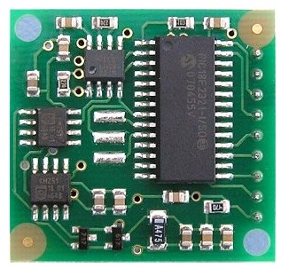
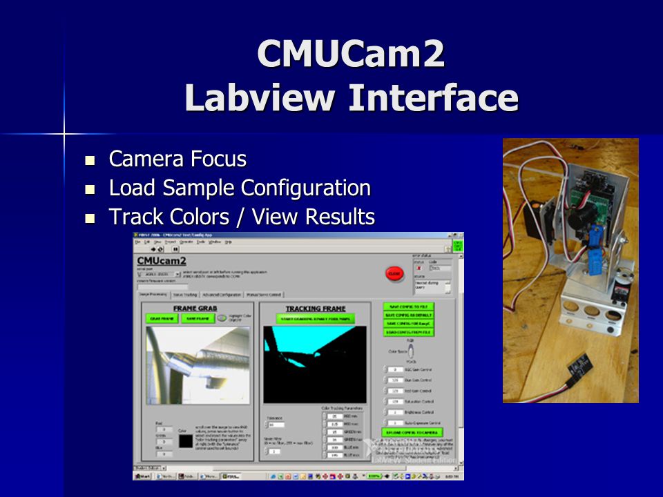
III . CMU cam2
A CMUcam is a low cost computer vision device intended for robotics research. CMUcams consist of a small video camera and a microcontroller with a serial interface. While other digital cameras typically use a much higher bandwidth connector, the CMUcam's lightweight interface allows it to be accessed by microcontrollers. More importantly, the on-board microprocessor supports simple image processing and color blob tracking, making rudimentary computer vision capable in systems that would previously have far too little power to do such a thing. It has been used in past years by the high-school FIRST Robotics Competition as a way of letting participants' robots track field elements and navigate autonomously. The CMUcam also has an extremely small form factor. For these reasons, it is relatively popular for making small, mobile robots.
The original design was originally made by Carnegie Mellon University, who has licensed it to various manufacturers.
Pixy2 is the latest in the line of CMUcam sensors. It adds line tracking capability and an onboard light source to the previous CMUcam5, aka original Pixy. These sensors are produced in collaboration with Charmed Labs in Austin, TX.


_____________________________________________________________________
IV . VEXTA MOTOR ( STEPPER MOTOR )
Structure of Stepper Motors
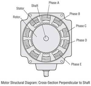
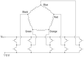
The figures below show two cross-sections of a 5-phase stepper motor. The stepper motor consists primarily of two parts: a stator and rotor. The rotor is made up of three components: rotor 1, rotor 2 and a permanent magnet. The rotor is magnetized in the axial direction so that, for example, if rotor 1 is polarized north, rotor 2 will be polarized south.
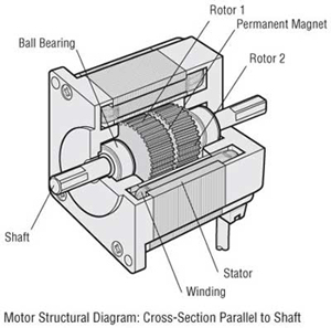
The stator has ten magnetic poles with small teeth, each pole being provided with a winding. Each winding is connected to the winding of the opposite pole so that both poles are magnetized in the same polarity when current is sent through the pair of windings. (Running a current through a given winding magnetizes the opposing pair of poles in the same polarity, i.e., north or south.)
The opposing pair of poles constitutes one phase. Since there are five phases, A through E, the motor is called a "5-phase stepper motor."
There are 50 small teeth on the outer perimeter of each rotor, with the small teeth of rotor 1 and rotor 2 being mechanically offset from each other by half a tooth pitch.
Excitation: To send current through a motor winding
Magnetic pole: A projected part of the stator, magnetized by excitation
Small teeth: The teeth on the rotor and stator
Magnetic pole: A projected part of the stator, magnetized by excitation
Small teeth: The teeth on the rotor and stator
Principle of Operation
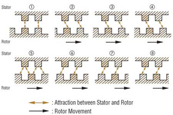
Following is an explanation of the relationship between the magnetized stator small teeth and rotor small teeth.
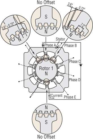
When Phase "A" is Excited
When phase A is excited, its poles are polarized south. This attracts the teeth of rotor 1, which are polarized north, while repelling the teeth of rotor 2, which are polarized south. Therefore, the forces on the entire unit in equilibrium hold the rotor stationary. At this time, the teeth of the phase B poles, which are not excited, are misaligned with the south-polarized teeth of rotor 2 so that they are offset 0.72˚. This summarizes the relationship between the stator teeth and rotor teeth with phase A excited.
When Phase "B" is Excited
When excitation switches from phase A to B, the phase B poles are polarized north, attracting the south polarity of rotor 2 and repelling the north polarity of rotor 1.
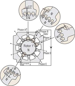
In other words, when excitation switches from phase A to B, the rotor rotates by 0.72˚. As excitation shifts from phase A, to phases B, C, D and E, then back around to phase A, the stepping motor rotates precisely in 0.72˚ steps. To rotate in reverse, reverse the excitation sequence to phase A, E, D, C, B, then back around to phase A.
High resolution of 0.72˚ is inherent in the mechanical offset between the stator and rotor, accounting for the achievement of precise positioning without the use of an encoder or other sensors. High stopping accuracy of }3 arc minutes (with no load) is obtained, since the only factors affecting stopping accuracy are variations in the machining precision of the stator and rotor, assembly precision and DC resistance of windings.
The driver performs the role of phase switching, and its timing is controlled by a pulse-signal input to the driver. The example above shows the excitation advancing one phase at a time, but in an actual stepper motor an effective use of the windings is made by exciting four or five phases simultaneously.
Basic Characteristics of Stepper Motors
An important point to consider in the application of stepper motors is whether the motor characteristics are suitable to the operating conditions.
The following sections describe the characteristics to be considered in the application of stepper motors.
The two main characteristics of stepper motor performance are:
The following sections describe the characteristics to be considered in the application of stepper motors.
The two main characteristics of stepper motor performance are:
- Dynamic Characteristics: These are the starting and rotational characteristics of a stepper motor, mainly affecting the machinery’s movement and cycling time.
- Static Characteristics: These are the characteristics relating to the changes in angle that take place when the stepper motor is in standstill mode, affecting the machinery’s level of precision.
Dynamic Characteristics
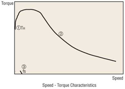
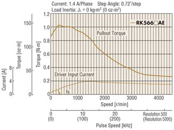
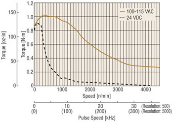
Speed – Torque Characteristics The figure above is a characteristics graph showing the relationship between the speed and torque of a driven stepper motor. These characteristics are always referred to in the selection of a stepper motor. The horizontal axis represents the speed at the motor output shaft, and the vertical axis represents the torque. The speed – torque characteristics are determined by the motor and driver, and are greatly affected by the type of driver being used.
- Maximum holding torque (TH) The maximum holding torque is the stepper motor’s maximum holding power (torque) when power is supplied (at rated current) when the motor is not rotating.
- Pullout torque The pullout torque is the maximum torque that can be output at a given speed. When selecting a motor, be sure the required torque falls within this curve.
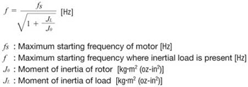
- Maximum starting frequency (fS) This is the maximum pulse speed at which the motor can start or stop instantly (without an acceleration/deceleration time) when the stepper motor’s friction load and inertial load are 0. Driving the motor at a pulse speed in excess of this rate will require a gradual acceleration or deceleration. This frequency will decrease when an inertial load is added to the motor. Refer to the inertial load – starting frequency characteristics below.
Maximum response frequency (fr) This is the maximum pulse speed at which the motor can be operated through gradual acceleration or deceleration when the stepper motor’s friction load and inertial load are 0. The figure below shows the speed – torque characteristics of a 5-phase stepper motor and driver package.
Inertial Load – Starting Frequency Characteristics These characteristics show the changes in the starting frequency caused by the load inertia. Since the stepper motor’s rotor and load have their own moment of inertia, lags and advances occur on the motor axis during instantaneous starting and stopping. These values change with the pulse speed, but the motor cannot follow the pulse speed beyond a certain point, so that missteps result. The pulse speed immediately before the occurrence of a misstep is called the starting frequency.
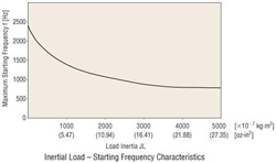
Changes in maximum starting frequency with the inertial load may be approximated via the following formula:
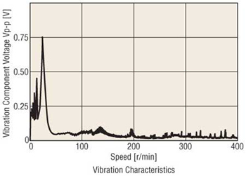
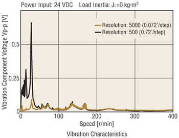
Vibration Characteristics
The stepper motor rotates through a series of stepping movements. A stepping movement may be described as a 1-step response, as shown below:
1. A single pulse input to a stepper motor at a standstill accelerates the motor toward the next stop position.
2. The accelerated motor rotates through the stop position, overshoots a certain angle, and is pulled back in reverse.
3. The motor settles to a stop at the set stop position following a damping oscillation.
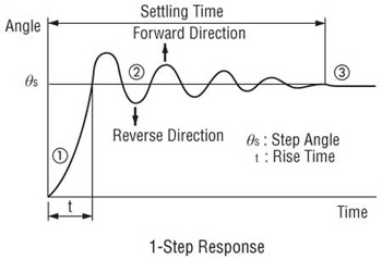
Vibration at low speeds is caused by a step-like movement that produces this type of damping oscillation. The vibration characteristics graph below represents the magnitude of vibration of a motor in rotation. The lower the vibration level, the smoother the motor rotation will be.
Static Characteristics
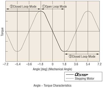
Angle – Torque Characteristics: The angle – torque characteristics show the relationship between the angular displacement of the rotor and the torque externally applied to the motor shaft while the motor is excited at the rated current. The curve for these characteristics is shown below:
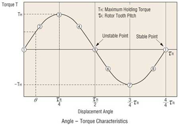
The following illustrations show the positional relationship between the rotor teeth and stator teeth at the numbered points in the diagram above. When held stable at point (1) the external application of a force to the motor shaft will produce torque T (+) in the left direction, trying to return the shaft to stable point (1). The shaft will stop when the external force equals this torque at point (2).
If additional external force is applied, there is an angle at which the torque produced will reach its maximum at point (3). This torque is called the maximum holding torque TH.
Application of external force in excess of this value will drive the rotor to an unstable point (5) and beyond, producing torque T (−) in the same direction as the external force, so that it moves to the next stable point (1) and stops.
Stable Points: Points where the rotor stops, with the stator teeth and rotor teeth are exactly aligned. These points are extremely stable, and the rotor will always stop there if no external force is applied.
Unstable Points: Points where the stator teeth and rotor teeth are half a pitch out of alignment. A rotor at these points will move to the next stable point to the left or right, even under the slightest external force.
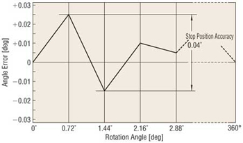
Angle Accuracy
Under no load conditions, a stepper motor has an angle accuracy within ±3 arc minutes (±0.05˚). The small error arises from the difference in mechanical precision of the stator and rotor and a small variance in the DC resistance of the stator winding. Generally, the angle accuracy of the stepper motor is expressed in terms of the stop position accuracy.
Stop Position Accuracy: The stop position accuracy is the difference between the rotor’s theoretical stopping position and its actual stopping position. A given rotor stopping point is taken as the starting point, then the stop position accuracy is the difference between the maximum (+) value and maximum (−) value in the set of measurements taken for each step of a full rotation.
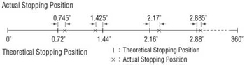
The stop position accuracy is within ±3 arc minutes (±0.05˚), but only under no load conditions. In actual applications there is always the same amount of friction load. The angle accuracy in such cases is produced by the angular displacement caused by the angle – torque characteristics based upon the friction load. If the friction load is constant, the displacement angle will be constant for uni-directional operation.
However, in bi-directional operation, double the displacement angle is produced over a round trip. When high stopping accuracy is required, always position in the same direction.
Excitation Sequence of Stepper Motor and Driver Packages
Every 5-phase motor and driver package listed in our catalog consists of a New Pentagon, five-lead wire motor and a driver incorporating a special excitation sequence. This combination, which is proprietary to Oriental Motor, offers the following benefits:
- Simple connections for five leads
- Low vibration
The following sections describe the wiring and excitation sequence.
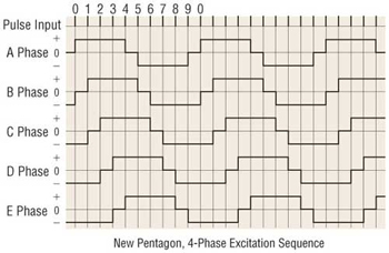
New Pentagon, 4-Phase Excitation: Full Step System (0.72˚/step)
This is a system unique to the 5-phase motor, in which four phases are excited. The step angle is 0.72˚ (0.36˚). It offers a great damping effect, and therefore stable operation.
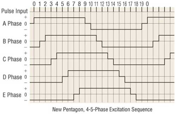
New Pentagon, 4-5-Phase Excitation: Half-Step System (0.36˚/step)
A step sequence of alternating the 4-phase and 5-phase excitation produces rotation at 0.36˚ per step. One rotation may be divided into 1000 steps.
Stepper Motor Drivers
There are two common systems of driving a stepper motor: constant current drive and constant voltage drive. The circuitry for the constant voltage drive is simpler, but it’s relatively more difficult to achieve torque performance at high speeds.
The constant current drive, on the other hand, is now the most commonly used drive method, since it offers excellent torque performance at high speeds. All Oriental Motor’s drivers use the constant current drive system.
The constant current drive, on the other hand, is now the most commonly used drive method, since it offers excellent torque performance at high speeds. All Oriental Motor’s drivers use the constant current drive system.
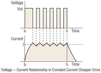
Overview of the Constant Current Drive System
The stepper motor rotates through the sequential switching of current flowing through the windings. When the speed increases, the switching rate also becomes faster and the current rise falls behind, resulting in lost torque. The chopping of a DC voltage that is far higher than the motor’s rated voltage will ensure the rated current reaches the motor, even at higher speeds.
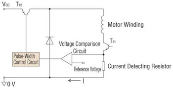
The current flowing to the motor windings, detected as a voltage through a current detecting resistor, is compared to the reference voltage. Current control is accomplished by holding the switching transistor Tr2 ON when the voltage across the detecting resistor is lower than the reference voltage (when it hasn’t reached the rated current), or turning Tr2 OFF when the value is higher than the reference voltage (when it exceeds the rated current), thereby providing a constant flow of rated current.
Differences between AC Input and DC Input Characteristics
A stepper motor is driven by a DC voltage applied through a driver. In Oriental Motor’s 24 VDC input motor and driver packages, 24 VDC is applied to the motor. In the 100-115 VAC motor and driver packages the input is rectified to DC and then approximately 140 VDC is applied to the motor. (Certain products are exceptions to this.)
This difference in voltages applied to the motors appears as a difference in torque characteristics at high speeds. This is due to the fact that the higher the applied voltage is, the faster the current rise through the motor windings will be, facilitating the application of rated current at higher speeds.
Thus, the AC input motor and driver package has superior torque characteristics over a wide speed range, from low to high speeds, offering a large speed ratio. It is recommended that AC input motor and driver packages, which are compatible with a wider range of operating conditions, be considered for your applications.
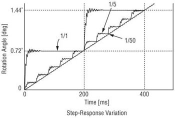
Microstep Drive Technology
Microstep drive technology is used to divide the basic step angle (0.72˚) of the 5-phase stepping motor into smaller steps (up to a maximum of 250 divisions) without the use of a speed reduction mechanism.
◇ Microstep Drive Technology
The stepper motor moves and stops in increments of the step angle determined by the rotor and stator’s salient pole structure, easily
achieving a high degree of precision in positioning. The stepper motor, on the other hand, causes the rotor speed to vary because
the motor rotates in step angle increments, resulting in resonance or greater vibration at a given speed.
achieving a high degree of precision in positioning. The stepper motor, on the other hand, causes the rotor speed to vary because
the motor rotates in step angle increments, resulting in resonance or greater vibration at a given speed.
Microstepping is a technology that achieves low resonance, low noise operation at extremely low speeds by controlling the flow of
electric current fed to the motor coil and thereby dividing the motor’s basic step angle into smaller steps.
electric current fed to the motor coil and thereby dividing the motor’s basic step angle into smaller steps.
- The motor’s basic step angle (0.72˚/full step) can be divided into smaller steps ranging from 1/1 to 1/250. Microstepping thus ensures smooth operation.
- With the technology for smoothly varying the motor drive current, motor vibration can be minimized for low noise operation.
◇ Up to 250 Microsteps
Thanks to the microstep driver, different step angles (16 steps up to 250 divisions) can be set to two step angle setting switches. By controlling the input signal for step angle switching via an external source, it is possible to switch the step angle between the levels set for the respective switches.
Features of Microstep Drive
● Low Vibration
Microstep drive technology electronically divides the step angle into smaller steps, ensuring smooth incremental motion at low speeds and significantly reducing vibration. While a damper or similar device is generally used to reduce vibration, the low vibration design employed for the motor itself — along with the microstep drive technology — minimizes vibration more effectively. Anti-vibration measures can be dramatically simplified, so it’s ideal for most vibration sensitive applications and equipment.
● Low Noise
Microstep drive technology effectively reduces the vibration related noise level at low speeds, achieving low noise performance. The motor demonstrates outstanding performance in even the most noise sensitive environment.
Microstep drive technology effectively reduces the vibration related noise level at low speeds, achieving low noise performance. The motor demonstrates outstanding performance in even the most noise sensitive environment.
● Improved Controllability
The New Pentagon microstep driver, with its superior damping performance, minimizes overshoot and undershoot in response to step changes, accurately following the pulse pattern and ensuring improved linearity. In addition, shock normally resulting from the motions of starting and stopping can be lessened.
Stepper Motor and Driver Package
Overview of the Control System
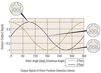
◇ The Sensor to Detect Rotor’s Position
A rotor position detection sensor is built into the counter end of the motor output shaft:
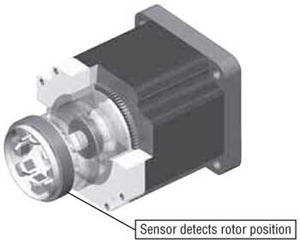
The sensor winding detects changes in magnetic reluctance due to the angular position of the rotor.
Featuring Innovative Closed Loop Control
The deviation counter calculates the deviation (lag/advance) of the rotor’s actual angular position with regard to the position command by the pulse signal. The calculation result is used to detect a “misstep region” and operate the motor by switching between open loop and closed loop modes.
- If the positioning deviation is less than }1.8˚, the motor runs in the open loop mode.
- If the positioning deviation is }1.8˚ or more, the motor runs in closed loop mode.
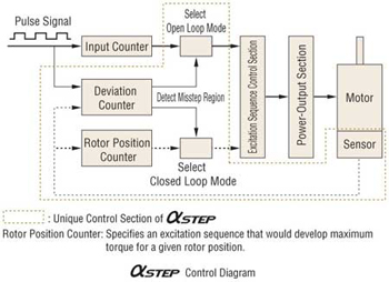
In the closed loop mode, motor-winding excitation is controlled so that maximum torque is developed for the given angular position of the rotor. This control method eliminates unstable points (misstep region) in the angle – torque characteristics.
Features of AlphaStep
◇ Improved Stepper Motor Performance
- At high speeds will not “misstep.” Therefore, unlike conventional stepper motors, the operation will be free of the following restrictions:
- Restrictions on acceleration/deceleration rates and inertia ratio stemming from the pulse profile of the controller.
- Restrictions on starting pulse speed caused by “misstep.”
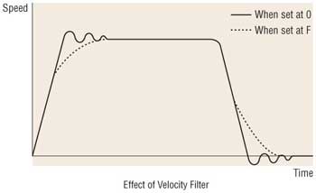
- Use the velocity filter to adjust responsiveness while starting/ stopping. The responsiveness of starting/stopping can be adjusted with 16 settings without changing the controller data (starting pulse, acceleration/deceleration rates). This feature is intended to reduce shock to the work and vibration during low speed operation.
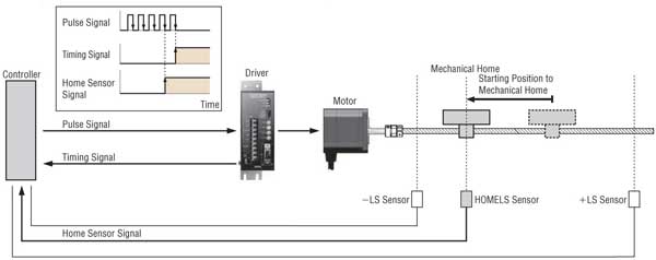
Return to Mechanical Home Operation Using Excitation Timing Signal
● Excitation Timing Signal
The excitation timing (TIM.) signal is output when the driver is initially exciting the stepper motor (step "0"). Oriental Motor's 5-phase stepper motor and driver packages perform initial excitation when the power is turned on, and advance the excitation
sequence each time a pulse signal is input, completing one cycle when the motor shaft rotates 7.2˚.
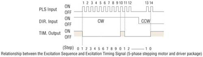
Use these timing signals when it is necessary to perform highly reproducible return to mechanical home operation. The following sections describe stepper motor return to mechanical home operation and the use of timing signals.
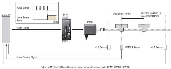
● Return to Mechanical Home Operation for Stepper Motors
When turning on the power to start automated equipment or restarting the equipment after a power failure, it is necessary to return stepper motors to their standard position. This operation is called the "return to mechanical home operation."
The return to mechanical home operation for stepper motors uses home sensors to detect the mechanical component used for the positioning operation. When the detected signals are confirmed, the controller stops the pulse signal, and the stepper motor is stopped. The accuracy of the home position in such a return to mechanical home operation depends on the detection performance of the home sensors. As the detection performance of the home sensors varies according to factors such as the ambient temperature and approach speed of the mechanism detection area, it's necessary to reduce these factors for applications that require a highly reproducible mechanical home position detecting.
● Improved Reproducibility Using Excitation Timing Signal
A method of ensuring that the mechanical home position does not vary due to variations in the detection performance of the home sensors, is to stop the pulse signal by logically multiplying with the timing signal. As the timing signal is output at initial excitation, if the pulse signal is stopped when the timing signal is output, the mechanical home position will always be determined at initial excitation.
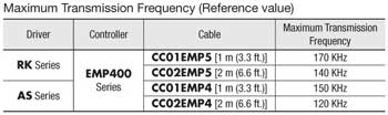
Relationship between Cable Length and Transmission Frequency
As the pulse line cable becomes longer, the maximum transmission frequency decreases. Specifically, the resistive component and stray capacitance of the cable cause the formation of a CR circuit, thereby delaying the pulse rise and fall times. Stray capacitance in a cable occurs between electrical wires and ground planes. However, it is difficult to provide distinct numerical data, because conditions vary according to the cable type, layout, routing and other factors.
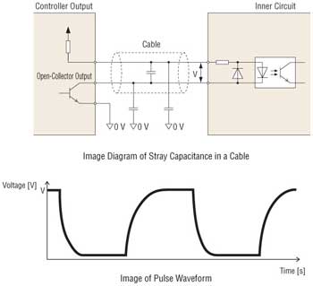
The transmission frequency when operated in combination with our products (actual-measurement reference values) are shown below:
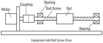
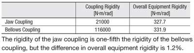
Effect of Coupling Rigidity on Equipment
The specifications that indicate coupling performance include permissible load, permissible speed, torsional spring constant, backlash (play) in the coupling, and permissible misalignment. In practice, when selecting couplings for equipment that requires high positioning performance or low vibration, the primary selection criteria would be "rigid, with no backlash." However, in some cases coupling rigidity has only a slight effect on the equipment's overall rigidity.
This section provides an example by comparing the overall rigidity of equipment consisting of a ball screw drive in two applications where a jaw coupling such as an MCS and a bellows coupling offering higher rigidity are used. (Data is taken from KTR's technical document, for which reason the coupling dimensions differ from the products offered by Oriental Motor.)
Overview of Test Equipment
Specifications of Parts
Torsional spring constant of jaw coupling
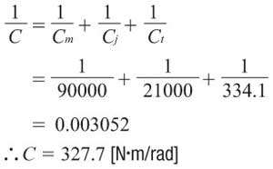
Cj = 21000 [N・m/rad]
Cj = 21000 [N・m/rad]
Torsional spring constant of bellows coupling
Cb = 116000 [N・m/rad]
Cb = 116000 [N・m/rad]
Servo motor rigidity
Cm = 90000 [N・m/rad]
Cm = 90000 [N・m/rad]
Ball screw lead
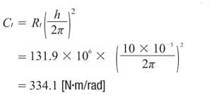
h = 10 [mm]
h = 10 [mm]
Ball screw root circle diameter
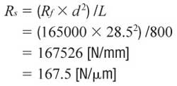
d = 28.5 [mm]
d = 28.5 [mm]
Ball screw length
L = 800 [mm]
L = 800 [mm]
Bearing rigidity in axial direction
Rbrg = 750 [N/μm]
Rbrg = 750 [N/μm]
Rigidity in axial direction of ball screw nut
Rn = 1060 [N/μm]
Rn = 1060 [N/μm]
Modulus of elasticity of ball screw
Rf = 165000 [N/mm2]
Rf = 165000 [N/mm2]
1. Obtain the torsional rigidity of the ball screw, bearing and nut. The rigidity in the axial direction of the ball screw Rs is calculated as follows:
Therefore, the total rigidity in the axial direction of the ball screw, bearing and nut Rt is calculated as follows:
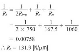
This rigidity in the axial direction is applied as torsional rigidity Ct.
2. Obtain the overall equipment rigidity C when a jaw coupling is used.
3. Obtain the overall equipment rigidity C when a bellows coupling is used.
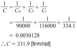
4. Calculation Results
________________________________________________________________________
V. Proximity sensor .
Inductive, Capacitive, Ultrasonic, IR? These are the common types of proximity sensors used today for varying applications, ranging from Andriod and iPhone proximity sensing, to distance measurement, object detection, with Arduino. Hence, picking one that’s easily connectable, accurate, and reliable is very much important for fulfilling your intended usages.
In this guide, I’ll cover the various proximity sensor types, its uses, and price, with recommendations to make your decision an easier one!
This guide will cover the following components:
- What are proximity sensors?
- Types of proximity sensors
- How to pick a proximity sensor
- Honorable mentions
- Proximity sensor compared (Summary)
What are proximity sensors? Overview

Proximity sensors are sensors that detect movement/presence of objects without physical contact and relay that information captured into an electrical signal. It can also be defined as a proximity switch, a definition given by the Japanese Industrial Standards (JIS) to all contactless detecting sensors
- Sounds complex? Proximity sensor simply means; A sensor that detects, captures, and relays information without any physical contact!
Proximity Sensor Features
To further understand what proximity sensor is all about, we’ll take a look at its features. The following is its features, with some uniquely seen as compared to traditional optical/contact sensors:
Contactless sensing
Contactless proximity sensing allows for detection without touching the object, ensuring object stays well-conditioned
Unaffected by surface conditions
Proximity sensors are nearly unaffected by surface colors of objects since it mainly detects physical changes
Suitability for wide range of applications
Proximity sensors are suitable for damp conditions and wide temperature range usage, unlike your traditional optical detection.
Proximity sensors are also applicable in phones as well, be it your Andriod or IOS devices. It consists of simple IR technology that switches on and off display accordingly to your usage. For example, it turns off your display when a phone call is ongoing such that you wouldn’t accidentally activate something while placing it near your cheeks!
Longer service life
Since a proximity sensor uses semiconductor outputs, there are no moving parts dependent on the operating cycle. Thus, its service life tends to be longer as compared to traditional sensors!
High speed response rate
Compared to switches where contact is required for sensing, proximity sensors offer a higher-speed response rate.
Types of proximity sensor
Now that we’ve understood what proximity sensors are, we’ll dive further into the various types; each well suited to its specific applications and environments.
Ready? Here’s the rundown of the different proximity sensor types!
Inductive Proximity Sensors
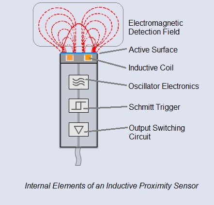
Inductive proximity sensors are contactless sensors used to only detect metal objects. It’s based on the law of induction, driving a coil with an oscillator once a metallic object approaches it.
It has two versions and comprises of 4 main components:
Versions:
- Unshielded: Electromagnetic field generated by the coil is unrestricted, allowing for wider and greater sensing distances
- Shielded: Electromagnetic field generated is concentrated in the front, where sides of the sensor coil are covered up
Components:
- It comprises of 4 main components as seen in the picture; Coil, Oscillator, Schmitt Trigger, and output switching circuit
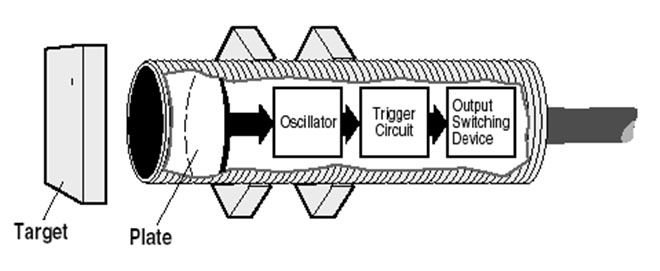
How does Inductive Proximity Sensor work?
- An alternating current is supplied to the coil, generating an electromagnetic detection field
- When a metal object comes closer into the magnetic field, eddy currents build-up, and result in coil inductance changes
- When coil inductance changes, the circuit that has been continuously monitoring, will trigger the sensor’s output switch
*Note: Even when a target is not present, inductive sensors continue to oscillate. The switch is only triggered when an object is present.
Common applications:
- Industrial usages
- Production automation machines that count products, product transfers
- Security usages
- Detection of metal objects, armory, land mines, etc.
Advantages of inductive proximity sensors
- Contactless detection
- Environment adaptability; resistant to common conditions seen in industrial areas such as dust and dirt
- Capable and versatile in metal sensing
- Considerably cheap when it comes to price
- No moving parts, ensuring a longer service life
Disadvantages of inductive proximity sensors
- Lack in detection range, averaging a max range of up to 80mm
- Can only detect metal objects
- Performance can be affected by external conditions; extreme temperatures,
cutting fluids or chemicals
Inductive Sensors offered at Seeed
Grove – 2-Channel Inductive Sensor (LDC1612)

Here at Seeed, we offer this inductive sensor, where it enables the performance and reliability benefits of inductive sensing to be realized at minimal cost and power.
Expanding beyond just proximity sensing, its Arduino compatible with the capability of remote sensing applications and many other possibilities!
Capacitive Proximity Sensors
Capacitive proximity sensors are contactless sensors that detect both metallic and non-metallic objects, including liquid, powders, and granular. It operates by detecting a change in capacitance.
Similarly to inductive sensors, it consists of an oscillator, Schmitt trigger and output switching circuit. The only difference is it comprises of 2 charging plates (1 internal, 1 external) for capacitation:
- Internal plate connected to the oscillator
- External plate (sensor electrodes) used as the sensing surface
How do capacitive proximity sensors work?
- Capacitive proximity sensor produces an electrostatic field
- When an object (conductive/non-conductive) approaches the sensing area, the capacitance of both plates increases, resulting in oscillator amplitude gain
- The resulted amplitude gain triggers sensor output switch
*Note: Capacitive sensors only oscillate when the target object is present
Common applications:
- Industrial usages
- Production automation machines that count products, product transfers
- Filling processes, pipelines, inks, etc.
- Fluid level, composition, and pressure
- Moisture control
- Non-invasive content detection
- Touch applications
Advantages of Capacitive proximity sensors
- Contactless detection
- A wide array of materials able to be detected
- Able to detect objects through non-metallic walls with its wide sensitivity band
- Well-suited to be used in an industrial environment
- Contains potentiometer that allows users to adjust sensor sensitivity, such that only wanted objects will be sensed
- No moving parts, ensuring a longer service life
Disadvantages of Capacitive proximity sensors
- Relative low range, though incremental increase from inductive sensors
- Higher price as compared to inductive sensors
Capacitive Sensors offered at Seeed
Grove – Capacitive Moisture Sensor (Corrosion Resistant)

Since we’ve now understood that capacitive proximity sensors are capable of moisture control, we’ll, of course, need a sensor for its applications!
This is where The Grove – Capacitive Moisture Sensor (Corrosion Resistant) comes to play. It’s a soil moisture sensor based on capacitance changes. Compared with resistive sensors, not only is it corrosion resistant, it offers a wide range of applications!
Grove – 12 Key Capacitive I2C Touch Sensor V2 (MPR121)

Need a module that does more than just capacitative proximity sensing? We got just that!
The Grove – 12 Key Capacitive I2C Touch Sensor V2 (MPR121) is a 3-in-1 module with the following features: Capacitance Sensing, Touch Sensing, and Proximity Sensing.
Ultrasonic Proximity Sensors

Third on this list is ultrasonic proximity sensors, detecting the presence of objects through emitting high-frequency ultrasonic range. It does so through the conversion of electrical energy. Similarly to capacitive sensors, it can detect objects in solid, liquid, granular, or granular as well.
Probably the easiest among all, it only comprises an ultrasonic transmitter and an ultrasonic receiver.
How does Ultrasonic Proximity Sensor work?
- The sonic transducer emits sonic waves
- Sonic waves bounces off the object
- The wave that bounced off is then returned to the sensor
- Time that it took to emit and receive sound waves is then used to determine distance/proximity
Common applications
- Distance measurement
- Anemometers for wind speed and direction detection
- Automation production processes
- Fluid detection
- Unmanned aerial vehicles (UAVs) for object monitoring
- Robotics
Advantages of ultrasonic proximity sensors
- Contactless detection
- Not affected by object color and transparency
- Not affected by external environmental conditions, reliable solution
- Works well in places with extreme conditions
- Able to be used in dark environments
- Low current consumption
Disadvantages of an ultrasonic proximity sensors
- Limited detection range though capable of higher range as compared to inductive and capacitive sensors
- Doesn’t work in a vacuum since ultrasonic sensors operate via sound waves
- Not able to measure the distance of Soft objects or ones with extreme textures
Ultrasonic sensors offered at Seeed
Grove – Ultrasonic Sensor: Improved version of the HC-SR04
Made with significant benefits over the traditional HC-SR04 ultrasonic sensor, the Grove – Ultrasonic Sensor is the perfect ultrasonic module for not just proximity sensing, but as for distance measurement and ultrasonic detector. as well!
IR Proximity Sensor
IR, in short for infrared, detects the presence of an object by emitting a beam of infrared light. It works similarly to ultrasonic sensors, though instead of using sonic waves, IR is transmitted.
Infrared proximity sensors consist of an IR LED that emits, and a light detector for detection of reflection. It has an in-built signal processing circuit that determines an optical spot on the PSD.
How do IR proximity sensors work?
- Infrared light is emitted from the IR LED emitter
- The beam of light hits the object and gets reflected back in an angle
- The reflected light will reach the light detector
- The sensor in the light detector determines the position/distance of reflective object
Common applications
- Distance measurement
- Item counter; when object cuts the radiating light, it counts as one
- Security systems such as surveillance, burglar alarms, etc.
- Monitoring and control applications
Advantages of IR proximity sensors
- Contactless detection
- Applicable for daytime and nighttime usages
- Secured communication through a line of sight
- Able to measure the distance to soft objects unlike ultrasound proximity sensors
- Accuracy of the infrared sensor not affected by corrosion or oxidation
Disadvantages of IR proximity sensors
- Affected by environmental conditions and hard objects, implying inability fo usage through walls or doors
- Requires line of sight between transmitter and receiver for communication
- Performance dips over longer distances
Infrared Proximity Sensor offered at Seeed
Grove – 80cm Infrared Proximity Sensor

Based on the SHARP GP2Y0A21, this IR proximity sensor is a popular choice that I’m recommending for anyone that’s looking for accurate distance measuring beyond your alternatives.
Packed in a small package with low power consumption, this IR proximity sensor allows for continuous distance reading with a range of 10cm to 80cm!
How to choose a suitable proximity sensor
Now to help you select a suitable one out of the four, I’ve provided criteria that you should consider when making a proximity sensor selection.
However, as always, you’ll have to first consider your intended purpose; What are you trying to use it for in the first place.
An additional factor that’s worth noting is the electrical system that you’re integrating the proximity sensor with. Be it, electrical load (NPN/PNP) or voltage supply (AC/DC), the sensor must function with the system controls you’re running.
Honorable mentions
Now that I’ve covered the criteria for proximity sensor consideration, here’s a list of some honorable mentions that are still worth taking a look at!
Photoelectric Proximity Sensor
Photoelectric proximity sensors are ones that use high-end photoelectric technology, it emits a light beam that’s capable of detecting all sorts of objects!
It has the following 3 different models; Reflective, Through-beam, and Retro-reflective. Each model offers varying light emission methods, though they are all highly efficient when it comes to distance detection.
If you’re interested in such proximity sensing technology, you can check this sensor that integrates it into a small package:
PSK-CM8JL65-CC5 Infrared Distance Measuring Sensor

Magnetic Proximity Sensor
Magnetic proximity sensors are proximity devices used to detect magnetic objects through their large sensing ranges. A typical one incorporates glass and metal blade, allowing for quick magnetizing!
Though it merely senses magnets, it’s still great for its low cost, long-range, and small dimensions.
If you fancy one and would like to know more about it, you can check out this:
Grove – 12-bit Magnetic Rotary Position Sensor / Encoder (AS5600)

Based on the A5600, this Magnetic Rotary Position Sensor is not only capable of contactless proximity sensing needs, but it contains significant advantages over regular encoders as well. Precise, programmable and cost-effective, it’s an option to consider!
LiDAR Proximity Sensor
LiDar, in short for Light Detection and Ranging, is a higher-end sensing technology that provides excellent max detection range with fast update rates. The only main downside is the cost, where it may be too costly for the average consumer.
Fear not though, here at Seeed, we offer a mini LiDAR proximity sensor that’s very much affordable!

Summary
To summarise, here are the proximity sensors compared with its recommended usages:
For proximity sensor Arduino compatibility, You can consider the recommended Seeed products covered for each proximity sensor type! This will save you time in trying to make one yourself as well!
- Inductive sensor recommendation:
- Capacitive sensor recommendation:
- Ultrasonic sensor recommendation:
- IR sensor recommendation:
______________________________________________________________________
VI . Ultrasonic sensor
Ultrasonic sensing is one of the best ways to sense proximity and detect levels with high reliability.
Our technical support gets emails all of the time about how our sensors work and what environments our sensors work (or don’t work) in.
This guide was created as an introduction to ultrasonic sensing, it’s principles, and how ultrasonic sensors work in your applications.
At a top level, you need to know what an ultrasonic sensor is…
What is an ultrasonic sensor?
An ultrasonic sensor is an instrument that measures the distance to an object using ultrasonic sound waves.
An ultrasonic sensor uses a transducer to send and receive ultrasonic pulses that relay back information about an object’s proximity.
High-frequency sound waves reflect from boundaries to produce distinct echo patterns.
How Ultrasonic Sensors Work.
Ultrasonic sensors work by sending out a sound wave at a frequency above the range of human hearing. The transducer of the sensor acts as a microphone to receive and send the ultrasonic sound. Our ultrasonic sensors, like many others, use a single transducer to send a pulse and to receive the echo. The sensor determines the distance to a target by measuring time lapses between the sending and receiving of the ultrasonic pulse.
The working principle of this module is simple. It sends an ultrasonic pulse out at 40kHz which travels through the air and if there is an obstacle or object, it will bounce back to the sensor. By calculating the travel time and the speed of sound, the distance can be calculated.
Using Your Ultrasonic Sensor in Your Project
1. HOOK UP CONTROLLER
We used an Arduino in this example, but you can use another controller and program of your choice.
2. INSTALL SOFTWARE
Install Arduino Sketch coding software onto your PC. This is where you type the code you want to compile and send to the Arduino board.
3. SET UP YOUR SENSOR WITH ARDUINO
Plug your Arduino into the USB cable and into your computer. Once you upload Arduino, you can then compile and activate the code.
4. COMPILE AND RUN CODE
The code below will allow you to read distance in centimeters. Compile and run this code to obtain real-time distance measurements to the closest object. (Please note: this code is not only for Arduino and will run on most controllers)
Why use an Ultrasonic Sensor?
Ultrasound is reliable in any lighting environment and can be used inside or outside. Ultrasonic sensors can handle collision avoidance for a robot, and being moved often, as long as it isn’t too fast.
Ultrasonics are so widely used, they can be reliably implemented in grain bin sensing applications, water level sensing, drone applications and sensing cars at your local drive-thru restaurant or bank.
Ultrasonic rangefinders are commonly used as devices to detect a collision.
Ultrasonic Sensors are best used in the non-contact detection of:
- Presence
- Level
- Position
- Distance
Non-contact sensors are also referred to as proximity sensors.
Ultrasonics are Independent of:
- Light
- Smoke
- Dust
- Color
- Material (except for soft surfaces, i.e. wool, because the surface absorbs the ultrasonic sound wave and doesn’t reflect sound.)
Long range detection of targets with varied surface properties.
Ultrasonic sensors are superior to infrared sensors because they aren’t affected by smoke or black materials, however, soft materials which don’t reflect the sonar (ultrasonic) waves very well may cause issues. It’s not a perfect system, but it’s good and reliable.
Applications Involving Ultrasonic Detection:
Ultrasonic Distance Measuring
Distance measurement is based on the measurement of time-of-flight. The time between sending and receiving the reflected sound signal is calculated by the sensor. Ultrasonic distance sensors, like the MB7360 HRXL-MaxSonar-WR, are used as height monitors, in bin level measurement and proximity zone detection applications.
- Ex. Distance measurement would be applied in a garage parking application, sensing when a vehicle is pulled completely into a garage.
- The MB7360 has been used as a bin level sensor to detect the presence or absence of grain and other materials in bins.
People Detection with Ultrasonic Sensors
Popular applications that we have worked on have been using our sensors in kiosks to detect the presence of a person approaching and detecting the presence of people in an environment, like an art installation.
We’ve written an article which covers key questions and concerns about the use of our sensors in these types of solutions.
to learn:
- Why people are traditionally a challenging target for an ultrasonic sensor
- The target types that are ideal
- The benefits of an ultrasonic proximity sensor
Our goal is to help you find a sensor that is just sensitive enough for your project but avoids potential issues like picking up interference from an outside noise source.
Take a look at the following video. nu Media Innovations developed a solution for a Microsoft Store in Seattle WA to detect human presence on a store display.

Popular Sensors for Measuring Distance


Ultrasonic Level Sensors
- Tank level measurement, Fuel gauging, irrigation control.
- This project for a Low Power Water Level Sensor, from Hackster.io developer Amedee, uses a weather resistant sensor from our WR line. In combination with a LoraWan node and The Things IoT open source network, this project was developed to measure the water level in a rainwater tank. Although, it can be used in many applications.
Choosing a Level Sensor
- The important factors to consider when mounting your sensor
- How to handle using the sensor in an environment with harsh chemicals
- Which sensor lines work best for environments where frost on the sensor might be an issue
Using the sensor in harsh environments
If you’re using the sensor in a harsh environment, we suggest the added protection in order for you to successfully use the sensor in your project.
As a brief guide to inform you of the compatibility of our sensors in a few environments, we’ve created the Chemical Compatibility Chart.
Ordering a Fully Sealed Sensor
When you use a sensor from our WR line, the sensor pinout is left exposed, allowing you to attach wires and equipment to the sensor.
The reason we leave it open is that it provides you more flexibility in how you choose to connect to the sensors.
In some applications, it can leave the sensor exposed to the weather.
If your mounting requires you to protect the back of the sensor from damage, you must seal the sensor pinout.
The wire attach option will fully cover the sensor pinout by adding a small cap filled with an epoxy mixture and attached cable.
By adding the additional potting on the back of the sensor, it will seal it against the effects of weather, dust, and water…
This isn’t just for people that just want to protect their sensor, it’s for people with limited soldering experience.
If you don’t want to risk your new sensor with the first attempt soldering it, we highly suggest working with our professional, in house soldered sensors with wire attachments.
Popular Sensors for Liquid Level Sensing


Ultrasonic Obstacle Detection
- Our UAV Sensors for Drones as well as our proximity sensors that are used for robots are for obstacle detection.
- Ultrasonic sensors are suitable for close range detection up to ten meters and provide multiple range measurements per second.
- Main advantages:
- Low power consumption – can be powered by battery, inexpensively.
- It can operate in many environmental conditions – ultrasonic sensors work in smoke-filled environments, where other sensors would fail.
Autonomous Navigation and Obstacle Avoidance with Ultrasonic Sensors
We’ve had a lot of success working with companies, makers, and product developers in autonomous navigation projects.
Ultrasonic Sensors in UAV Operation
You can read this article, Ultrasonic Sensor Operation on a UAV, which covers issues you might encounter while working with UAVs and how you can mitigate some issues.
We give you notes to troubleshoot:
- Dealing with Air Turbulence
- Propeller Acoustic Noise
- Grounding and Power
- Conducted Electrical Noise
- Radiated Electric Noise
- Frame Vibration
If there are any issues not covered, please feel free to contact our team and we’ll assist you through the issue the best we can.
Comparing our Best 3 Sensors for Indoor Mobile Robotics
If you’re developing an autonomous navigation robot, you’ll want to review our article on the Best Ultrasonic Sensor for Indoor Mobile Robotics.
We guide you through the following:
- People detection and the rejection of side objects
- Recommended beam patterns and power recommendations
- The sensor operation over temperature
- The handling of the power supply voltage
- The handling of the rejection of noise sources
- Dealing with sensor cross-talk (Which sensor is best when cross talk may be a concern)
Using a Wide Beam Sensor for Obstacle Detection
We’ve developed wide beam variations of our widely used HRXL-MaxSonar-WR line of sensors.
These sensors include –
This sensor was developed so that you will have a sensor with a wide beam for your applications that require such.
You can review the image below to see how wide the beam pattern is:
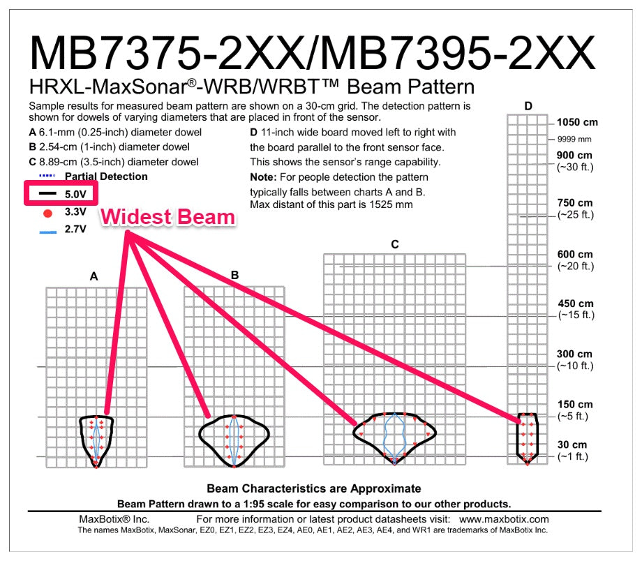
These sensors are easy to set up. No special settings are needed, and it offers a beam angle wider than 90 degrees to many targets.
_________________________________________________________________________
VII . ROTARY ENCODER
A rotary encoder, also called a shaft encoder, is an electro-mechanical device that converts the angular position or motion of a shaft or axle to analog or digital output signals.
There are two main types of rotary encoder: absolute and incremental. The output of an absolute encoder indicates the current shaft position, making it an angle transducer. The output of an incremental encoder provides information about the motion of the shaft, which typically is processed elsewhere into information such as position, speed and distance.
Rotary encoders are used in a wide range of applications that require monitoring or control, or both, of mechanical systems, including industrial controls, robotics, photographic lenses, computer input devices such as optomechanical mice and trackballs, controlled stress rheometers, and rotating radar platforms.
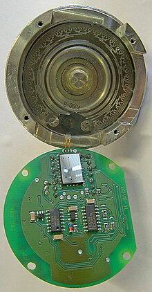
A Gray code absolute rotary encoder with 13 tracks. At the top, the housing, interrupter disk, and light source can be seen; at the bottom the sensing element and support components.
Encoder technologies

- Mechanical: Also known as conductive encoders. A series of circumferential copper tracks etched onto a PCB is used to encode the information via contact brushes sensing the conductive areas. Mechanical encoders are economical but susceptible to mechanical wear. They are common in human interfaces such as digital multimeters.[3]
- Optical: This uses a light shining onto a photodiode through slits in a metal or glass disc. Reflective versions also exist. This is one of the most common technologies. Optical encoders are very sensitive to dust.
- On-Axis Magnetic: This technology typically uses a specially magnetized 2 pole neodymium magnet attached to the motor shaft. Because it can be fixed to the end of the shaft, it can work with motors that only have 1 shaft extending out of the motor body. The accuracy can vary from a few degrees to under 1 degree. Resolutions can be as low as 1 degree or as high as 0.09 degree (4000 CPR, Count per Revolution).[4] Poorly designed internal interpolation can cause output jitter, but this can be overcome with internal sample averaging.
- Off-Axis Magnetic: This technology typically employs the use of rubber bonded ferrite magnets attached to a metal hub. This offers flexibility in design and low cost for custom applications. Due to the flexibility in many off axis encoder chips they can be programmed to accept any number of pole widths so the chip can be placed in any position required for the application. Magnetic encoders operate in harsh environments where optical encoders would fail to work.
Basic types
Absolute

An absolute encoder maintains position information when power is removed from the encoder.[5] The position of the encoder is available immediately on applying power. The relationship between the encoder value and the physical position of the controlled machinery is set at assembly; the system does not need to return to a calibration point to maintain position accuracy.
An absolute encoder has multiple code rings with various binary weightings which provide a data word representing the absolute position of the encoder within one revolution. This type of encoder is often referred to as a parallel absolute encoder.[6]
A multi-turn absolute rotary encoder includes additional code wheels and gears. A high-resolution wheel measures the fractional rotation, and lower-resolution geared code wheels record the number of whole revolutions of the shaft.
Incremental
An incremental encoder will immediately report changes in position, which is an essential capability in some applications. However, it does not report or keep track of absolute position. As a result, the mechanical system monitored by an incremental encoder may have to be homed (moved to a fixed reference point) to initialize absolute position measurements.
Absolute encoder
Absolute rotary encoder
Construction
Digital absolute encoders produce a unique digital code for each distinct angle of the shaft. They come in two basic types: optical and mechanical.
Mechanical absolute encoders
A metal disc containing a set of concentric rings of openings is fixed to an insulating disc, which is rigidly fixed to the shaft. A row of sliding contacts is fixed to a stationary object so that each contact wipes against the metal disc at a different distance from the shaft. As the disc rotates with the shaft, some of the contacts touch metal, while others fall in the gaps where the metal has been cut out. The metal sheet is connected to a source of electric current, and each contact is connected to a separate electrical sensor. The metal pattern is designed so that each possible position of the axle creates a unique binary code in which some of the contacts are connected to the current source (i.e. switched on) and others are not (i.e. switched off).
Because brush-type contacts are susceptible to wear, encoders using contacts are not common; they can be found in low-speed applications such as manual volume or tuning controls in a radio receiver.
Optical absolute encoders
The optical encoder's disc is made of glass or plastic with transparent and opaque areas. A light source and photo detector array reads the optical pattern that results from the disc's position at any one time. The Gray code is often used. This code can be read by a controlling device, such as a microprocessor or microcontroller to determine the angle of the shaft.
The absolute analog type produces a unique dual analog code that can be translated into an absolute angle of the shaft.
Magnetic absolute encoders
The magnetic encoder uses a series of magnetic poles (2 or more) to represent the encoder position to a magnetic sensor (typically magneto-resistive or Hall Effect). The magnetic sensor reads the magnetic pole positions.
This code can be read by a controlling device, such as a microprocessor or microcontroller to determine the angle of the shaft, similar to an optical encoder.
The absolute analog type produces a unique dual analog code that can be translated into an absolute angle of the shaft (by using a special algorithm ).
Due to the nature of recording magnetic effects, these encoders may be optimal to use in conditions where other types of encoders may fail due to dust or debris accumulation. Magnetic encoders are also relatively insensitive to vibrations, minor misalignment, or shocks.
- Brushless motor commutation
Built-in rotary encoders are used to indicate the angle of the motor shaft in permanent magnet brushless motors, which are commonly used on CNC machines, robots, and other industrial equipment. In such cases, the encoder serves as a feedback device that plays a vital role in proper equipment operation. Brushless motors require electronic commutation, which often is implemented in part by using rotor magnets as a low-resolution absolute encoder (typically six or twelve pulses per revolution). The resulting shaft angle information is conveyed to the servo drive to enable it to energize the proper stator winding at any moment in time.
Capacitive absolute encoders
An asymmetrical shaped disc is rotated within the encoder. This disc will change the capacitance between two electrodes which can be measured and calculated back to an angular value.
Absolute multi-turn encoder
A multi-turn encoder can detect and store more than one revolution. The term absolute multi-turn encoder is generally used if the encoder will detect movements of its shaft even if the encoder is not provided with external power.
Battery-powered multi-turn encoder
This type of encoder uses a battery for retaining the counts across power cycles. It uses energy conserving electrical design to detect the movements.
Geared multi-turn encoder
These encoders use a train of gears to mechanically store the number of revolutions. The position of the single gears is detected with one of the above-mentioned technologies.
Self-powered multi-turn encoder
These encoders use the principle of energy harvesting to generate energy from the moving shaft. This principle, introduced in 2007, uses a Wiegand Sensor to produce electricity sufficient to power the encoder and write the turns count to non-volatile memory.
Ways of encoding shaft position
Standard binary encoding
.svg)
An example of a binary code, in an extremely simplified encoder with only three contacts, is shown below.
| Sector | Contact 1 | Contact 2 | Contact 3 | Angle |
|---|---|---|---|---|
| 0 | off | off | off | 0° to 45° |
| 1 | off | off | ON | 45° to 90° |
| 2 | off | ON | off | 90° to 135° |
| 3 | off | ON | ON | 135° to 180° |
| 4 | ON | off | off | 180° to 225° |
| 5 | ON | off | ON | 225° to 270° |
| 6 | ON | ON | off | 270° to 315° |
| 7 | ON | ON | ON | 315° to 360° |
In general, where there are n contacts, the number of distinct positions of the shaft is 2n. In this example, n is 3, so there are 2³ or 8 positions.
In the above example, the contacts produce a standard binary count as the disc rotates. However, this has the drawback that if the disc stops between two adjacent sectors, or the contacts are not perfectly aligned, it can be impossible to determine the angle of the shaft. To illustrate this problem, consider what happens when the shaft angle changes from 179.9° to 180.1° (from sector 3 to sector 4). At some instant, according to the above table, the contact pattern changes from off-on-on to on-off-off. However, this is not what happens in reality. In a practical device, the contacts are never perfectly aligned, so each switches at a different moment. If contact 1 switches first, followed by contact 3 and then contact 2, for example, the actual sequence of codes is:
- off-on-on (starting position)
- on-on-on (first, contact 1 switches on)
- on-on-off (next, contact 3 switches off)
- on-off-off (finally, contact 2 switches off)
Now look at the sectors corresponding to these codes in the table. In order, they are 3, 7, 6 and then 4. So, from the sequence of codes produced, the shaft appears to have jumped from sector 3 to sector 7, then gone backwards to sector 6, then backwards again to sector 4, which is where we expected to find it. In many situations, this behaviour is undesirable and could cause the system to fail. For example, if the encoder were used in a robot arm, the controller would think that the arm was in the wrong position, and try to correct the error by turning it through 180°, perhaps causing damage to the arm.
Gray encoding
.svg)
To avoid the above problem, Gray coding is used. This is a system of binary counting in which any two adjacent codes differ by only one bit position. For the three-contact example given above, the Gray-coded version would be as follows.
| Sector | Contact 1 | Contact 2 | Contact 3 | Angle |
|---|---|---|---|---|
| 0 | off | off | off | 0° to 45° |
| 1 | off | off | ON | 45° to 90° |
| 2 | off | ON | ON | 90° to 135° |
| 3 | off | ON | off | 135° to 180° |
| 4 | ON | ON | off | 180° to 225° |
| 5 | ON | ON | ON | 225° to 270° |
| 6 | ON | off | ON | 270° to 315° |
| 7 | ON | off | off | 315° to 360° |
In this example, the transition from sector 3 to sector 4, like all other transitions, involves only one of the contacts changing its state from on to off or vice versa. This means that the sequence of incorrect codes shown in the previous illustration cannot happen.
Single-track Gray encoding
If the designer moves a contact to a different angular position (but at the same distance from the center shaft), then the corresponding "ring pattern" needs to be rotated the same angle to give the same output. If the most significant bit (the inner ring in Figure 1) is rotated enough, it exactly matches the next ring out. Since both rings are then identical, the inner ring can be omitted, and the sensor for that ring moved to the remaining, identical ring (but offset at that angle from the other sensor on that ring). Those two sensors on a single ring make a quadrature encoder with a single ring.
It is possible to arrange several sensors around a single track (ring) so that consecutive positions differ at only a single sensor; the result is the single-track Gray code encoder.
Data output methods
Depending on the device and manufacturer, an absolute encoder may use any of several signal types and communication protocols to transmit data, including parallel binary, analog signals (current or voltage), and serial bus systems such as SSI, BiSS, DeviceNet, Modbus, Profibus, CANopen and EtherCAT, which typically employ Ethernet or RS-422/RS-485 physical layers.
Incremental encoder


The rotary incremental encoder is the most widely used of all rotary encoders due to its ability to provide real-time position information. The measurement resolution of an incremental encoder is not limited in any way by its two internal, incremental movement sensors; one can find in the market incremental encoders with up to 10,000 counts per revolution, or more.
Rotary incremental encoders report position changes without being prompted to do so, and they convey this information at data rates which are orders of magnitude faster than those of most types of absolute shaft encoders. Because of this, incremental encoders are commonly used in applications that require precise measurement of position and velocity.
A rotary incremental encoder may use mechanical, optical or magnetic sensors to detect rotational position changes. The mechanical type is commonly employed as a manually operated "digital potentiometer" control on electronic equipment. For example, modern home and car stereos typically use mechanical rotary encoders as volume controls. Encoders with mechanical sensors require switch debouncing and consequently are limited in the rotational speeds they can handle. The optical type is used when higher speeds are encountered or a higher degree of precision is required.
A rotary incremental encoder has two output signals, A and B, which issue square waves in quadrature when the encoder shaft rotates. The square wave frequency indicates the speed of shaft rotation, whereas the A-B phase relationship indicates the direction of rotation.
Some rotary incremental encoders have an additional "index" output (typically labeled Z), which emits a pulse when the shaft passes through a particular angle. Once every rotation, the Z signal is asserted, typically always at the same angle, until the next AB state change. This is commonly used in radar systems and other applications that require a registration signal when the encoder shaft is located at a particular reference angle.
Unlike absolute encoders, an incremental encoder does not keep track of, nor do its outputs indicate the absolute position of the mechanical system to which it is attached. Consequently, to determine the absolute position at any particular moment, it is necessary to "track" the absolute position with an incremental encoder interface.
Inexpensive incremental encoders are used in mechanical computer mice. Typically, two encoders are used: one to sense left-right motion and another to sense forward-backward motion.
Other pulse-output rotary encoders
Rotary encoders with a single output (i.e. tachometers) cannot be used to sense direction of motion but are suitable for measuring speed and for measuring position when the direction of travel is constant. In certain applications they may be used to measure distance of motion (e.g. feet of movement).
Analogue devices that perform a similar function include the synchro, the resolver, the rotary variable differential transformer (RVDT), and the rotary potentiometer.
A linear encoder is similar to a rotary encoder, but measures position in a straight line, rather than rotation. Linear encoders often use incremental encoding and are used in many machine tools.

_________________________________________________________________________
VIII . PWM for regulate Velocity DC motor
The circuit is used to control speed of DC motor by using PWM technique. Series Variable Speed DC Motor Controller 12V uses a 555 timer IC as a PWM pulse generator to regulate the motor speed DC12 Volt. IC 555 is the popular Timer Chip used to make timer circuits. It was introduced in 1972 by the Signetics.
But before we start looking at the in’s and out’s of pulse width modulation we need to understand a little more about how a DC motor works.
Next to stepper motors, the Permanent Magnet DC Motor (PMDC) is the most commonly used type of small direct current motor available producing a continuous rotational speed that can be easily controlled. Small DC motors ideal for use in applications were speed control is required such as in small toys, models, robots and other such electronics circuits.
A DC motor consist basically of two parts, the stationary body of the motor called the “Stator” and the inner part which rotates producing the movement called the “Rotor”. For D.C. machines the rotor is commonly termed the “Armature”.
Generally in small light duty DC motors the stator consists of a pair of fixed permanent magnets producing a uniform and stationary magnetic flux inside the motor giving these types of motors their name of “permanent-magnet direct-current” (PMDC) motors.
The motors armature consists of individual electrical coils connected together in a circular configuration around its metallic body producing a North-Pole then a South-Pole then a North-Pole etc, type of field system configuration.
The current flowing within these rotor coils producing the necessary electromagnetic field. The circular magnetic field produced by the armatures windings produces both north and south poles around the armature which are repelled or attracted by the stator’s permanent magnets producing a rotational movement around the motors central axis as shown.
2-Pole Permanent Magnet Motor

As the armature rotates electrical current is passed from the motors terminals to the next set of armature windings via carbon brushes located around the commutator producing another magnetic field and each time the armature rotates a new set of armature windings are energised forcing the armature to rotate more and more and so on.
So the rotational speed of a DC motor depends upon the interaction between two magnetic fields, one set up by the stator’s stationary permanent magnets and the other by the armatures rotating electromagnets and by controlling this interaction we can control the speed of rotation.
The magnetic field produced by the stator’s permanent magnets is fixed and therefore can not be changed but if we change the strength of the armatures electromagnetic field by controlling the current flowing through the windings more or less magnetic flux will be produced resulting in a stronger or weaker interaction and therefore a faster or slower speed.
Then the rotational speed of a DC motor (N) is proportional to the back emf (Vb) of the motor divided by the magnetic flux (which for a permanent magnet is a constant) times an electromechanical constant depending upon the nature of the armatures windings (Ke) giving us the equation of: N ∝ V/KeΦ.

So how do we control the flow of current through the motor. Well many people attempt to control the speed of a DC motor using a large variable resistor (Rheostat) in series with the motor as shown.
While this may work, as it does with Scalextric slot car racing, it generates a lot of heat and wasted power in the resistance. One simple and easy way to control the speed of a motor is to regulate the amount of voltage across its terminals and this can be achieved using “Pulse Width Modulation” or PWM.
As its name suggests, pulse width modulation speed control works by driving the motor with a series of “ON-OFF” pulses and varying the duty cycle, the fraction of time that the output voltage is “ON” compared to when it is “OFF”, of the pulses while keeping the frequency constant.
The power applied to the motor can be controlled by varying the width of these applied pulses and thereby varying the average DC voltage applied to the motors terminals. By changing or modulating the timing of these pulses the speed of the motor can be controlled, ie, the longer the pulse is “ON”, the faster the motor will rotate and likewise, the shorter the pulse is “ON” the slower the motor will rotate.
In other words, the wider the pulse width, the more average voltage applied to the motor terminals, the stronger the magnetic flux inside the armature windings and the faster the motor will rotate and this is shown below.
Pulse Width Modulated Waveform
Because of its good speed regulation performance and control performance, DC motor is still widely used in many fields. Currently, in the field of the DC Speed regulation, the pulse width modulation speed control technology is developing rapidly, and has very broad application prospects. PWM DC Speed Regulating System Design are researched and discussed, including designs of PWM power conversion circuit, control circuit, protection circuit and other circuits of the system, and the corresponding parameter calculation and component selection

The use of pulse width modulation to control a small motor has the advantage in that the power loss in the switching transistor is small because the transistor is either fully “ON” or fully “OFF”. As a result the switching transistor has a much reduced power dissipation giving it a linear type of control which results in better speed stability.
Also the amplitude of the motor voltage remains constant so the motor is always at full strength. The result is that the motor can be rotated much more slowly without it stalling. So how can we produce a pulse width modulation signal to control the motor. Easy, use an Astable 555 Oscillator circuit as shown below.

This simple circuit based around the familiar NE555 or 7555 timer chip is used to produced the required pulse width modulation signal at a fixed frequency output. The timing capacitor C is charged and discharged by current flowing through the timing networks RA and RB as we looked at in the 555 Timer tutorial.
The output signal at pin 3 of the 555 is equal to the supply voltage switching the transistors fully “ON”. The time taken for C to charge or discharge depends upon the values of RA, RB.
The capacitor charges up through the network RA but is diverted around the resistive network RB and through diode D1. As soon as the capacitor is charged, it is immediately discharged through diode D2 and network RB into pin 7. During the discharging process the output at pin 3 is at 0 V and the transistor is switched “OFF”.
Then the time taken for capacitor, C to go through one complete charge-discharge cycle depends on the values of RA, RB and C with the time T for one complete cycle being given as:
The time, TH, for which the output is “ON” is: TH = 0.693(RA).C
The time, TL, for which the output is “OFF” is: TL = 0.693(RB).C
Total “ON”-“OFF” cycle time given as: T = TH + TL with the output frequency being ƒ = 1/T
With the component values shown, the duty cycle of the waveform can be adjusted from about 8.3% (0.5V) to about 91.7% (5.5V) using a 6.0V power supply. The Astable frequency is constant at about 256 Hz and the motor is switched “ON” and “OFF” at this rate.
Resistor R1 plus the “top” part of the potentiometer, VR1 represent the resistive network of RA. While the “bottom” part of the potentiometer plus R2 represent the resistive network of RB above.
These values can be changed to suite different applications and DC motors but providing that the 555 Astable circuit runs fast enough at a few hundred Hertz minimum, there should be no jerkiness in the rotation of the motor.
Diode D3 is our old favourite the flywheel diode used to protect the electronic circuit from the inductive loading of the motor. Also if the motor load is high put a heatsink on the switching transistor or MOSFET.
Pulse width modulation is a great method of controlling the amount of power delivered to a load without dissipating any wasted power. The above circuit can also be used to control the speed of a fan or to dim the brightness of DC lamps or LED’s. If you need to control it, then use Pulse Width Modulation to do it.
_________________________________________________________________
IX . SERVO MOTOR
How Do Servo Motors Work?
Servo Motor Controllers
This little motor is high in efficiency and power
Servo motors have been around for a long time and are utilized in many applications. They are small in size but pack a big punch and are very energy-efficient. These features allow them to be used to operate remote-controlled or radio-controlled toy cars, robots and airplanes. Servo motors are also used in industrial applications, robotics, in-line manufacturing, pharmaceutics and food services. But how do the little guys work?The servo circuitry is built right inside the motor unit and has a positionable shaft, which usually is fitted with a gear (as shown below). The motor is controlled with an electric signal which determines the amount of movement of the shaft.
What's inside the servo?
To fully understand how the servo works, you need to take a look under the hood. Inside there is a pretty simple set-up: a small DC motor, potentiometer, and a control circuit. The motor is attached by gears to the control wheel. As the motor rotates, the potentiometer's resistance changes, so the control circuit can precisely regulate how much movement there is and in which direction.When the shaft of the motor is at the desired position, power supplied to the motor is stopped. If not, the motor is turned in the appropriate direction. The desired position is sent via electrical pulses through the signal wire. The motor's speed is proportional to the difference between its actual position and desired position. So if the motor is near the desired position, it will turn slowly, otherwise it will turn fast. This is called proportional control. This means the motor will only run as hard as necessary to accomplish the task at hand, a very efficient little guy.
How is the servo controlled?
 The guts of a servo motor (L) and an assembled servo (R)
Servos are controlled by sending an electrical pulse of variable width, or pulse width modulation (PWM), through the control wire. There is a minimum pulse, a maximum pulse, and a repetition rate. A servo motor can usually only turn 90° in either direction for a total of 180° movement. The motor's neutral position is defined as the position where the servo has the same amount of potential rotation in the both the clockwise or counter-clockwise direction. The PWM sent to the motor determines position of the shaft, and based on the duration of the pulse sent via the control wire; the rotor will turn to the desired position. The servo motor expects to see a pulse every 20 milliseconds (ms) and the length of the pulse will determine how far the motor turns. For example, a 1.5ms pulse will make the motor turn to the 90° position. Shorter than 1.5ms moves it in the counter clockwise direction toward the 0° position, and any longer than 1.5ms will turn the servo in a clockwise direction toward the 180° position.
 Variable Pulse width control servo position
When these servos are commanded to move, they will move to the position and hold that position. If an external force pushes against the servo while the servo is holding a position, the servo will resist from moving out of that position. The maximum amount of force the servo can exert is called the torque rating of the servo. Servos will not hold their position forever though; the position pulse must be repeated to instruct the servo to stay in position.
Types of Servo Motors
There are two types of servo motors - AC and DC. AC servo can handle higher current surges and tend to be used in industrial machinery. DC servos are not designed for high current surges and are usually better suited for smaller applications. Generally speaking, DC motors are less expensive than their AC counterparts. These are also servo motors that have been built specifically for continuous rotation, making it an easy way to get your robot moving. They feature two ball bearings on the output shaft for reduced friction and easy access to the rest-point adjustment potentiometer.Servo Motor Applications
Servos are used in radio-controlled airplanes to position control surfaces like elevators, rudders, walking a robot, or operating grippers. Servo motors are small, have built-in control circuitry and have good power for their size.In food services and pharmaceuticals, the tools are designed to be used in harsher environments, where the potential for corrosion is high due to being washed at high pressures and temperatures repeatedly to maintain strict hygiene standards. Servos are also used in in-line manufacturing, where high repetition yet precise work is necessary.
_________________________________________________________________________
X . HUMANOID ROBOT
A humanoid robot is a robot with its body shape built to resemble the human body. The design may be for functional purposes, such as interacting with human tools and environments, for experimental purposes, such as the study of bipedal locomotion, or for other purposes. In general, humanoid robots have a torso, a head, two arms, and two legs, though some forms of humanoid robots may model only part of the body, for example, from the waist up. Some humanoid robots also have heads designed to replicate human facial features such as eyes and mouths. Androids are humanoid robots built to aesthetically resemble humans.
Humanoid robots are now used as research tools in several scientific areas. Researchers study the human body structure and behavior (biomechanics) to build humanoid robots. On the other side, the attempt to simulate the human body leads to a better understanding of it. Human cognition is a field of study which is focused on how humans learn from sensory information in order to acquire perceptual and motor skills. This knowledge is used to develop computational models of human behavior and it has been improving over time.
It has been suggested that very advanced robotics will facilitate the enhancement of ordinary humans. See transhumanism.
Although the initial aim of humanoid research was to build better orthosis and prosthesis for human beings, knowledge has been transferred between both disciplines. A few examples are powered leg prosthesis for neuromuscularly impaired, ankle-foot orthosis, biological realistic leg prosthesis and forearm prosthesis.

Besides the research, humanoid robots are being developed to perform human tasks like personal assistance, through which they should be able to assist the sick and elderly, and dirty or dangerous jobs. Humanoids are also suitable for some procedurally-based vocations, such as reception-desk administrators and automotive manufacturing line workers. In essence, since they can use tools and operate equipment and vehicles designed for the human form, humanoids could theoretically perform any task a human being can, so long as they have the proper software. However, the complexity of doing so is immense.
They are also becoming increasingly popular as entertainers. For example, Ursula, a female robot, sings, plays music, dances and speaks to her audiences at Universal Studios. Several Disney theme park shows utilize animatronic robots that look, move and speak much like human beings. Although these robots look realistic, they have no cognition or physical autonomy. Various humanoid robots and their possible applications in daily life are featured in an independent documentary film called Plug & Pray, which was released in 2010.
Humanoid robots, especially those with artificial intelligence algorithms, could be useful for future dangerous and/or distant space exploration missions, without having the need to turn back around again and return to Earth once the mission is completed.
A sensor is a device that measures some attribute of the world. Being one of the three primitives of robotics (besides planning and control), sensing plays an important role in robotic paradigms.
Sensors can be classified according to the physical process with which they work or according to the type of measurement information that they give as output. In this case, the second approach was used.
Proprioceptive
Proprioceptive sensors sense the position, the orientation and the speed of the humanoid's body and joints.
In human beings the otoliths and semi-circular canals (in the inner ear) are used to maintain balance and orientation. In addition humans use their own proprioceptive sensors (e.g. touch, muscle extension, limb position) to help with their orientation. Humanoid robots use accelerometers to measure the acceleration, from which velocity can be calculated by integration; tilt sensors to measure inclination; force sensors placed in robot's hands and feet to measure contact force with environment; position sensors, that indicate the actual position of the robot (from which the velocity can be calculated by derivation) or even speed sensors.
Exteroceptive

Arrays of tactels can be used to provide data on what has been touched. The Shadow Hand uses an array of 34 tactels arranged beneath its polyurethane skin on each finger tip.[2] Tactile sensors also provide information about forces and torques transferred between the robot and other objects.
Vision refers to processing data from any modality which uses the electromagnetic spectrum to produce an image. In humanoid robots it is used to recognize objects and determine their properties. Vision sensors work most similarly to the eyes of human beings. Most humanoid robots use CCD cameras as vision sensors.
Sound sensors allow humanoid robots to hear speech and environmental sounds, and perform as the ears of the human being. Microphones are usually used for this task.
Actuators
Humanoid robots are constructed in such a way that they mimic the human body, so they use actuators that perform like muscles and joints, though with a different structure. To achieve the same effect as human motion, humanoid robots use mainly rotary actuators. They can be either electric, pneumatic, hydraulic, piezoelectric or ultrasonic.Actuators are the motors responsible for motion in the robot.
Hydraulic and electric actuators have a very rigid behavior and can only be made to act in a compliant manner through the use of relatively complex feedback control strategies. While electric coreless motor actuators are better suited for high speed and low load applications, hydraulic ones operate well at low speed and high load applications.
Piezoelectric actuators generate a small movement with a high force capability when voltage is applied. They can be used for ultra-precise positioning and for generating and handling high forces or pressures in static or dynamic situations.
Ultrasonic actuators are designed to produce movements in a micrometer order at ultrasonic frequencies (over 20 kHz). They are useful for controlling vibration, positioning applications and quick switching.
Pneumatic actuators operate on the basis of gas compressibility. As they are inflated, they expand along the axis, and as they deflate, they contract. If one end is fixed, the other will move in a linear trajectory. These actuators are intended for low speed and low/medium load applications. Between pneumatic actuators there are: cylinders, bellows, pneumatic engines, pneumatic stepper motors and pneumatic artificial muscles.
Planning and control

In planning and control, the essential difference between humanoids and other kinds of robots (like industrial ones) is that the movement of the robot must be human-like, using legged locomotion, especially biped gait. The ideal planning for humanoid movements during normal walking should result in minimum energy consumption, as it does in the human body. For this reason, studies on dynamics and control of these kinds of structures has become increasingly important.
The question of walking biped robots stabilization on the surface is of great importance. Maintenance of the robot’s gravity center over the center of bearing area for providing a stable position can be chosen as a goal of control.
To maintain dynamic balance during the walk, a robot needs information about contact force and its current and desired motion. The solution to this problem relies on a major concept, the Zero Moment Point (ZMP).
Another characteristic of humanoid robots is that they move, gather information (using sensors) on the "real world" and interact with it. They don’t stay still like factory manipulators and other robots that work in highly structured environments. To allow humanoids to move in complex environments, planning and control must focus on self-collision detection, path planning and obstacle avoidance.
Humanoid robots do not yet have some features of the human body. They include structures with variable flexibility, which provide safety (to the robot itself and to the people), and redundancy of movements, i.e. more degrees of freedom and therefore wide task availability. Although these characteristics are desirable to humanoid robots, they will bring more complexity and new problems to planning and control. The field of whole-body control deals with these issues and addresses the proper coordination of numerous degrees of freedom, e.g. to realize several control tasks simultaneously while following a given order of priority.
A sensor is a device that measures some attribute of the world. Being one of the three primitives of robotics (besides planning and control), sensing plays an important role in robotic paradigms.
Sensors can be classified according to the physical process with which they work or according to the type of measurement information that they give as output. In this case, the second approach was used.
AI-based Interaction: The level at which humanoid robots can interact with humans is quite limited. This where Artificial Intelligence is critical. It can help decipher commands, questions, statements and might even be able to give witty, sarcastic replies and understand random, ambiguous human ramblings.

_________________________________________________________________________
GEN . MAC TECH on operation control ROBOT_ ICS
________________________________________________________________________
PHP MYSQL Advanced Search Feature
BalasHapusSimple Show Hide Menu Navigation
NodeJS Simple way to send SMTP mail
Simple pagination in PHP
Date Timestamp Formats in PHP
Getting IP address and type in Node js
R Plot Types
Php file based authentication
PHP user registration & login/ logout