when the population of the earth increased in early humans in the 20th and 21st century it only expects energy sources based on natural systems from the effects of I / O sources of gravity such as: alternating energy sources that occur due to gravity's gravitational pull system namely the north and south poles, wind energy systems are also formed from Earth's gravity, all mining materials are also influenced by the natural formation of the Earth's gravity theory which can be explained by EINSTEIN's postulates on G-Force 1, 2, 3, 4. although at some point EINSTEIN is honored to place the speed of light at E = MC ^ 2. because light is formed not from Earth's gravity but from a state of emptiness and nothingness in outer space so that empty space activates its radiation system to fill nothingness for a long time. when SUPERMAN observes outer space he is only a small beam between many radiation systems and modifiers, SUPERMAN requires SUPERGIRL to measure the distance of light and the speed of light transverse radiation while we are on earth under the influence of Earth's gravity so the measured is still below the standard speed. speed is directly proportional to the amount of energy.
Sincerely ,
AMNIMARJESLO SAN
( Gen. Mac Tech making 2 directions into 1 space fighter aircraft energy technique )
_____e- Solar Energy_____
Solar energy is the radiant light and heat from the sun that has been harnessed by humans since ancient times using a range of ever-evolving technologies. Solar radiation along with secondary solar resources account for most of the available renewable energy on earth.
because solar energy is used for needs on earth, it is usually used to be an AC supply component (alternating current), which uses an electronic INVERTER circuit and a DC supply component uses an accumulator. whereas outside the earth there will be an intersection of space and time on planets outside the earth because space and time are different so the energy graph and formulation system must be adjusted to the e-STAR C located there .
Solar energy is radiant light and heat from the Sun that is harnessed using a range of ever-evolving technologies such as solar heating, photovoltaics, solar thermal energy, solar architecture, molten salt power plants and artificial photosynthesis.
It is an important source of renewable energy and its technologies are broadly characterized as either passive solar or active solar depending on how they capture and distribute solar energy or convert it into solar power. Active solar techniques include the use of photovoltaic systems, concentrated solar power and solar water heating to harness the energy. Passive solar techniques include orienting a building to the Sun, selecting materials with favorable thermal mass or light-dispersing properties, and designing spaces that naturally circulate air.
The large magnitude of solar energy available makes it a highly appealing source of electricity. The United Nations Development Programme in its 2000 World Energy Assessment found that the annual potential of solar energy was 1,575–49,837 exajoules (EJ). This is several times larger than the total world energy consumption, which was 559.8 EJ in 2012.
In 2011, the International Energy Agency said that "the development of affordable, inexhaustible and clean solar energy technologies will have huge longer-term benefits. It will increase countries’ energy security through reliance on an indigenous, inexhaustible and mostly import-independent resource, enhance sustainability, reduce pollution, lower the costs of mitigating global warming, and keep fossil fuel prices lower than otherwise. These advantages are global. Hence the additional costs of the incentives for early deployment should be considered learning investments; they must be wisely spent and need to be widely shared .
Solar irradiation data is needed at all levels of solar power development, from initial government planning through to large-scale project development or the calculations needed to size smaller systems. In the past such data was provided at a relatively course level from NASA and other global providers, but more recently specialist models have been developed to more precisely calculate global horizontal irradiation (GHI) and direct normal irradiation (DNI) using primarily cloud cover data from satellites. A number of firms now offer such data as a commercial service. Based on this, it is possible to calculate average annual power output from a theoretical photovoltaic power plant (PVOUT), taking into account temperature, tilt, and the efficiency of the equipment being used (solar panels and balance of system components).
Solar energy technologies refer primarily to the use of solar radiation for practical ends. All other renewable energies other than geothermal derive their energy from energy received from the sun.
Solar technologies are broadly characterized as either passive solar or active solar depending on the way they capture, convert and distribute sunlight. Active solar techniques include the use of photovoltaic modules (also called photovoltaic panels) and solar thermal collectors (with electrical or mechanical equipment) to convert sunlight into useful outputs. Passive solar techniques include orienting a building to the Sun, selecting materials with favorable thermal mass or light dispersing properties, and designing spaces that naturally circulate air.
Active solar technologies increase the supply of energy and are considered supply side technologies, while passive solar technologies reduce the need for alternate resources and are generally considered demand side technologies .
Solar energy is the most abundant, renewable energy source in the world. Solar energy systems refer to technologies that convert the sun's heat or light to another form of energy for use.
There are two categories of technologies that harness solar energy, Solar Photovoltaics and Solar Thermal. Solar Photovoltaic (or PV) is a technology that converts sunlight into direct current electricity by using semiconductors. In contrast, Solar Thermal is a technology that utilizes the heat energy from the sun for heating or electricity production .
Solar is a renewable resource and does not emit any greenhouse gases in the energy generation process. However, the cost of solar in relation to other fuel sources is a barrier to adoption. Additionally, sunlight varies depending on geographic location, season, and time of day, which all creates limitations on its use.


Solar Power from Satellites

This
drawing shows how power collected by solar-power satellites might be
beamed to a receiving antenna on Earth. The antenna would convert the
energy back into electrical current, which would be fed into the power
grid. Courtesy: Space Studies Institute.
A satellite with solar panels to convert light energy into electricity can be put into orbit. Indeed, most satellites in orbit today are powered by solar panels. But how can we get the energy from the satellite back to earth? Clearly it would be impossible to use the electric lines we use for long-distance power transmission on earth. This is where microwaves come in.
The idea is that a satellite be equipped with a microwave generator, so that the electrical energy from the solar panels can be converted into a microwave beam. Then the microwave beam can be directed to antennas on the surface of the earth, which would convert the microwaves back to electrical energy. The energy could then either be used at the site of the antenna or injected into the electric-power network.
It was during the late 1960s that the engineer Peter Glaser first had the notion of solar power satellites. The principle of transmitting power by microwaves had already been demonstrated, though not put into practice. (Microwaves in practical devices, such as radar systems and long-distance telephone relays, were used to convey information.) To convey information, the intensity of the received signal need only be less than one nanowatt (one billionth of a watt). Glaser’s idea was to put the solar-power satellites in geosynchronous orbits, so that each would hover over a single location on the earth. This meant, however, that the satellites had to be very high (36,000 kilometers or about 22,000 feet), and this in turn meant that the antenna on the satellite and the receiving antenna on the ground had to be extremely large (a kilometer or more in diameter). The idea did not seem practical, and after some initial funding by the U.S Department of Energy and NASA there was little interest in pursuing the technology.
Today, however, the situation is changed because of the very large number of communications satellites in low orbits. It might be possible to make these satellites dual purpose—solar-energy collectors as well as communications devices. Because of the much lower orbits, the antennas on the satellites and on the ground need not be nearly so large. A drawback however, is that satellites in low-earth orbit circle the earth rapidly (about every 90 minutes) and therefore do not provide a connection for a very long time. There are also other concerns. One is that the transmission down to the ground might be interrupted by clouds and weather. Another is the safety of the people and animals near the receiving antennas who might be exposed to the microwave radiation. Today, the viability of solar-power satellites as a long-term solution to our energy needs is being investigated by government agencies and individual companies in many countries.
🔀 Power electronics ⬲
Power electronics is the application of solid-state electronics to the control and conversion of electric power.
The first high power electronic devices were mercury-arc valves. In modern systems, the conversion is performed with semiconductor switching devices such as diodes, thyristors, and power transistors such as the power MOSFET and IGBT. In contrast to electronic systems concerned with transmission and processing of signals and data, in power electronics substantial amounts of electrical energy are processed. An AC/DC converter (rectifier) is the most typical power electronics device found in many consumer electronic devices, e.g. television sets, personal computers, battery chargers, etc. The power range is typically from tens of watts to several hundred watts. In industry a common application is the variable speed drive (VSD) that is used to control an induction motor. The power range of VSDs start from a few hundred watts and end at tens of megawatts.
The power conversion systems can be classified according to the type of the input and output power
- AC to DC (rectifier)
- DC to AC (inverter)
- DC to DC (DC-to-DC converter)
- AC to AC (AC-to-AC converter)
A PCs power supply is an example of a piece of power electronics, whether inside or outside of the cabinet
DC to AC converters produce an AC output waveform from a DC source. Applications include adjustable speed drives (ASD), uninterruptible power supplies (UPS), Flexible AC transmission systems (FACTS), voltage compensators, and photovoltaic inverters. Topologies for these converters can be separated into two distinct categories: voltage source inverters and current source inverters. Voltage source inverters (VSIs) are named so because the independently controlled output is a voltage waveform. Similarly, current source inverters (CSIs) are distinct in that the controlled AC output is a current waveform.
DC to AC power conversion is the result of power switching devices, which are commonly fully controllable semiconductor power switches. The output waveforms are therefore made up of discrete values, producing fast transitions rather than smooth ones. For some applications, even a rough approximation of the sinusoidal waveform of AC power is adequate. Where a near sinusoidal waveform is required, the switching devices are operated much faster than the desired output frequency, and the time they spend in either state is controlled so the averaged output is nearly sinusoidal. Common modulation techniques include the carrier-based technique, or Pulse-width modulation, space-vector technique, and the selective-harmonic technique.
Voltage source inverters have practical uses in both single-phase and three-phase applications. Single-phase VSIs utilize half-bridge and full-bridge configurations, and are widely used for power supplies, single-phase UPSs, and elaborate high-power topologies when used in multicell configurations. Three-phase VSIs are used in applications that require sinusoidal voltage waveforms, such as ASDs, UPSs, and some types of FACTS devices such as the STATCOM. They are also used in applications where arbitrary voltages are required as in the case of active power filters and voltage compensators.[15]
Current source inverters are used to produce an AC output current from a DC current supply. This type of inverter is practical for three-phase applications in which high-quality voltage waveforms are required.
A relatively new class of inverters, called multilevel inverters, has gained widespread interest. Normal operation of CSIs and VSIs can be classified as two-level inverters, due to the fact that power switches connect to either the positive or to the negative DC bus. If more than two voltage levels were available to the inverter output terminals, the AC output could better approximate a sine wave. It is for this reason that multilevel inverters, although more complex and costly, offer higher performance.
Each inverter type differs in the DC links used, and in whether or not they require freewheeling diodes. Either can be made to operate in square-wave or pulse-width modulation (PWM) mode, depending on its intended usage. Square-wave mode offers simplicity, while PWM can be implemented several different ways and produces higher quality waveforms.
Voltage Source Inverters (VSI) feed the output inverter section from an approximately constant-voltage source.
The desired quality of the current output waveform determines which modulation technique needs to be selected for a given application. The output of a VSI is composed of discrete values. In order to obtain a smooth current waveform, the loads need to be inductive at the select harmonic frequencies. Without some sort of inductive filtering between the source and load, a capacitive load will cause the load to receive a choppy current waveform, with large and frequent current spikes.
There are three main types of VSIs:
- Single-phase half-bridge inverter
- Single-phase full-bridge inverter
- Three-phase voltage source inverter
Single-phase half-bridge inverter

Figure 8: The AC input for an ASD.

FIGURE 9: Single-Phase Half-Bridge Voltage Source Inverter
Low-order current harmonics get injected back to the source voltage by the operation of the inverter. This means that two large capacitors are needed for filtering purposes in this design. As Figure 9 illustrates, only one switch can be on at time in each leg of the inverter. If both switches in a leg were on at the same time, the DC source will be shorted out.
Inverters can use several modulation techniques to control their switching schemes. The carrier-based PWM technique compares the AC output waveform, vc, to a carrier voltage signal, vΔ. When vc is greater than vΔ, S+ is on, and when vc is less than vΔ, S- is on. When the AC output is at frequency fc with its amplitude at vc, and the triangular carrier signal is at frequency fΔ with its amplitude at vΔ, the PWM becomes a special sinusoidal case of the carrier based PWM. This case is dubbed sinusoidal pulse-width modulation (SPWM).For this, the modulation index, or amplitude-modulation ratio, is defined as ma = vc/v∆ .
The normalized carrier frequency, or frequency-modulation ratio, is calculated using the equation mf = f∆/fc .
If the over-modulation region, ma, exceeds one, a higher fundamental AC output voltage will be observed, but at the cost of saturation. For SPWM, the harmonics of the output waveform are at well-defined frequencies and amplitudes. This simplifies the design of the filtering components needed for the low-order current harmonic injection from the operation of the inverter. The maximum output amplitude in this mode of operation is half of the source voltage. If the maximum output amplitude, ma, exceeds 3.24, the output waveform of the inverter becomes a square wave.
As was true for Pulse Width Modulation (PWM), both switches in a leg for square wave modulation cannot be turned on at the same time, as this would cause a short across the voltage source. The switching scheme requires that both S+ and S- be on for a half cycle of the AC output period. The fundamental AC output amplitude is equal to vo1 = vaN = 2vi/π .
Its harmonics have an amplitude of voh = vo1/h.
Therefore, the AC output voltage is not controlled by the inverter, but rather by the magnitude of the DC input voltage of the inverter.
Using selective harmonic elimination (SHE) as a modulation technique allows the switching of the inverter to selectively eliminate intrinsic harmonics. The fundamental component of the AC output voltage can also be adjusted within a desirable range. Since the AC output voltage obtained from this modulation technique has odd half and odd quarter wave symmetry, even harmonics do not exist. Any undesirable odd (N-1) intrinsic harmonics from the output waveform can be eliminated.
Single-phase full-bridge inverter

FIGURE 3: Single-Phase Voltage Source Full-Bridge Inverter

FIGURE 4: Carrier and Modulating Signals for the Bipolar Pulsewidth Modulation Technique
To avoid shorting out the voltage source, S1+ and S1- cannot be on at the same time, and S2+ and S2- also cannot be on at the same time. Any modulating technique used for the full-bridge configuration should have either the top or the bottom switch of each leg on at any given time. Due to the extra leg, the maximum amplitude of the output waveform is Vi, and is twice as large as the maximum achievable output amplitude for the half-bridge configuration.
States 1 and 2 from Table 2 are used to generate the AC output voltage with bipolar SPWM. The AC output voltage can take on only two values, either Vi or –Vi. To generate these same states using a half-bridge configuration, a carrier based technique can be used. S+ being on for the half-bridge corresponds to S1+ and S2- being on for the full-bridge. Similarly, S- being on for the half-bridge corresponds to S1- and S2+ being on for the full bridge. The output voltage for this modulation technique is more or less sinusoidal, with a fundamental component that has an amplitude in the linear region of less than or equal to one vo1 =vab1= vi • ma.
Unlike the bipolar PWM technique, the unipolar approach uses states 1, 2, 3 and 4 from Table 2 to generate its AC output voltage. Therefore, the AC output voltage can take on the values Vi, 0 or –V [1]i. To generate these states, two sinusoidal modulating signals, Vc and –Vc, are needed, as seen in Figure 4.
Vc is used to generate VaN, while –Vc is used to generate VbN. The following relationship is called unipolar carrier-based SPWM vo1 =2 • vaN1= vi • ma.
The phase voltages VaN and VbN are identical, but 180 degrees out of phase with each other. The output voltage is equal to the difference of the two phase voltages, and do not contain any even harmonics. Therefore, if mf is taken, even the AC output voltage harmonics will appear at normalized odd frequencies, fh. These frequencies are centered on double the value of the normalized carrier frequency. This particular feature allows for smaller filtering components when trying to obtain a higher quality output waveform.
As was the case for the half-bridge SHE, the AC output voltage contains no even harmonics due to its odd half and odd quarter wave symmetry.
Three-phase voltage source inverter

FIGURE 5: Three-Phase Voltage Source Inverter Circuit Schematic
_Switch_State_S1_b)_Switch_State_S3_c)_S1_Output_d)_S3_Output.jpg)
FIGURE 6: Three-Phase Square-Wave Operation a) Switch State S1 b) Switch State S3 c) S1 Output d) S3 Output
Switches in any of the three legs of the inverter cannot be switched off simultaneously due to this resulting in the voltages being dependent on the respective line current's polarity. States 7 and 8 produce zero AC line voltages, which result in AC line currents freewheeling through either the upper or the lower components. However, the line voltages for states 1 through 6 produce an AC line voltage consisting of the discrete values of Vi, 0 or –Vi.
For three-phase SPWM, three modulating signals that are 120 degrees out of phase with one another are used in order to produce out of phase load voltages. In order to preserve the PWM features with a single carrier signal, the normalized carrier frequency, mf, needs to be a multiple of three. This keeps the magnitude of the phase voltages identical, but out of phase with each other by 120 degrees.The maximum achievable phase voltage amplitude in the linear region, ma less than or equal to one, is vphase = vi / 2. The maximum achievable line voltage amplitude is Vab1 = vab • √3 / 2
The only way to control the load voltage is by changing the input DC voltage.
Current source inverters

FIGURE 7: Three-Phase Current Source Inverter
_Carrier_and_Modulating_Signals_b)_S1_State_c)_S3_State_d)_Output_Current.jpg)
Figure 8:
Synchronized-Pulse-Width-Modulation Waveforms for a Three-Phase Current
Source Inverter a) Carrier and Modulating Signals b) S1 State c) S3
State d) Output Current

Figure 9: Space-Vector Representation in Current Source Inverters
In its most generalized form, a three-phase CSI employs the same conduction sequence as a six-pulse rectifier. At any time, only one common-cathode switch and one common-anode switch are on.
As a result, line currents take discrete values of –ii, 0 and ii. States are chosen such that a desired waveform is output and only valid states are used. This selection is based on modulating techniques, which include carrier-based PWM, selective harmonic elimination, and space-vector techniques.
Carrier-based techniques used for VSIs can also be implemented for CSIs, resulting in CSI line currents that behave in the same way as VSI line voltages. The digital circuit utilized for modulating signals contains a switching pulse generator, a shorting pulse generator, a shorting pulse distributor, and a switching and shorting pulse combiner. A gating signal is produced based on a carrier current and three modulating signals.
A shorting pulse is added to this signal when no top switches and no bottom switches are gated, causing the RMS currents to be equal in all legs. The same methods are utilized for each phase, however, switching variables are 120 degrees out of phase relative to one another, and the current pulses are shifted by a half-cycle with respect to output currents. If a triangular carrier is used with sinusoidal modulating signals, the CSI is said to be utilizing synchronized-pulse-width-modulation (SPWM). If full over-modulation is used in conjunction with SPWM the inverter is said to be in square-wave operation.
The second CSI modulation category, SHE is also similar to its VSI counterpart. Utilizing the gating signals developed for a VSI and a set of synchronizing sinusoidal current signals, results in symmetrically distributed shorting pulses and, therefore, symmetrical gating patterns. This allows any arbitrary number of harmonics to be eliminated. It also allows control of the fundamental line current through the proper selection of primary switching angles. Optimal switching patterns must have quarter-wave and half-wave symmetry, as well as symmetry about 30 degrees and 150 degrees. Switching patterns are never allowed between 60 degrees and 120 degrees. The current ripple can be further reduced with the use of larger output capacitors, or by increasing the number of switching pulses.
The third category, space-vector-based modulation, generates PWM load line currents that equal load line currents, on average. Valid switching states and time selections are made digitally based on space vector transformation. Modulating signals are represented as a complex vector using a transformation equation. For balanced three-phase sinusoidal signals, this vector becomes a fixed module, which rotates at a frequency, ω. These space vectors are then used to approximate the modulating signal. If the signal is between arbitrary vectors, the vectors are combined with the zero vectors I7, I8, or I9.[15] The following equations are used to ensure that the generated currents and the current vectors are on average equivalent.
Multilevel inverters
FIGURE 10: Three-Level Neutral-Clamped Inverter
Control methods for a three-level inverter only allow two switches of the four switches in each leg to simultaneously change conduction states. This allows smooth commutation and avoids shoot through by only selecting valid states. It may also be noted that since the DC bus voltage is shared by at least two power valves, their voltage ratings can be less than a two-level counterpart.
Carrier-based and space-vector modulation techniques are used for multilevel topologies. The methods for these techniques follow those of classic inverters, but with added complexity. Space-vector modulation offers a greater number of fixed voltage vectors to be used in approximating the modulation signal, and therefore allows more effective space vector PWM strategies to be accomplished at the cost of more elaborate algorithms. Due to added complexity and number of semiconductor devices, multilevel inverters are currently more suitable for high-power high-voltage applications. This technology reduces the harmonics hence improves overall efficiency of the scheme.
🔁Mars
Exploration Rovers🔃
Technologies of Broad Benefit:
Power
Power technologies provide more efficient and increased electricity to the spacecraft and its subsystems.
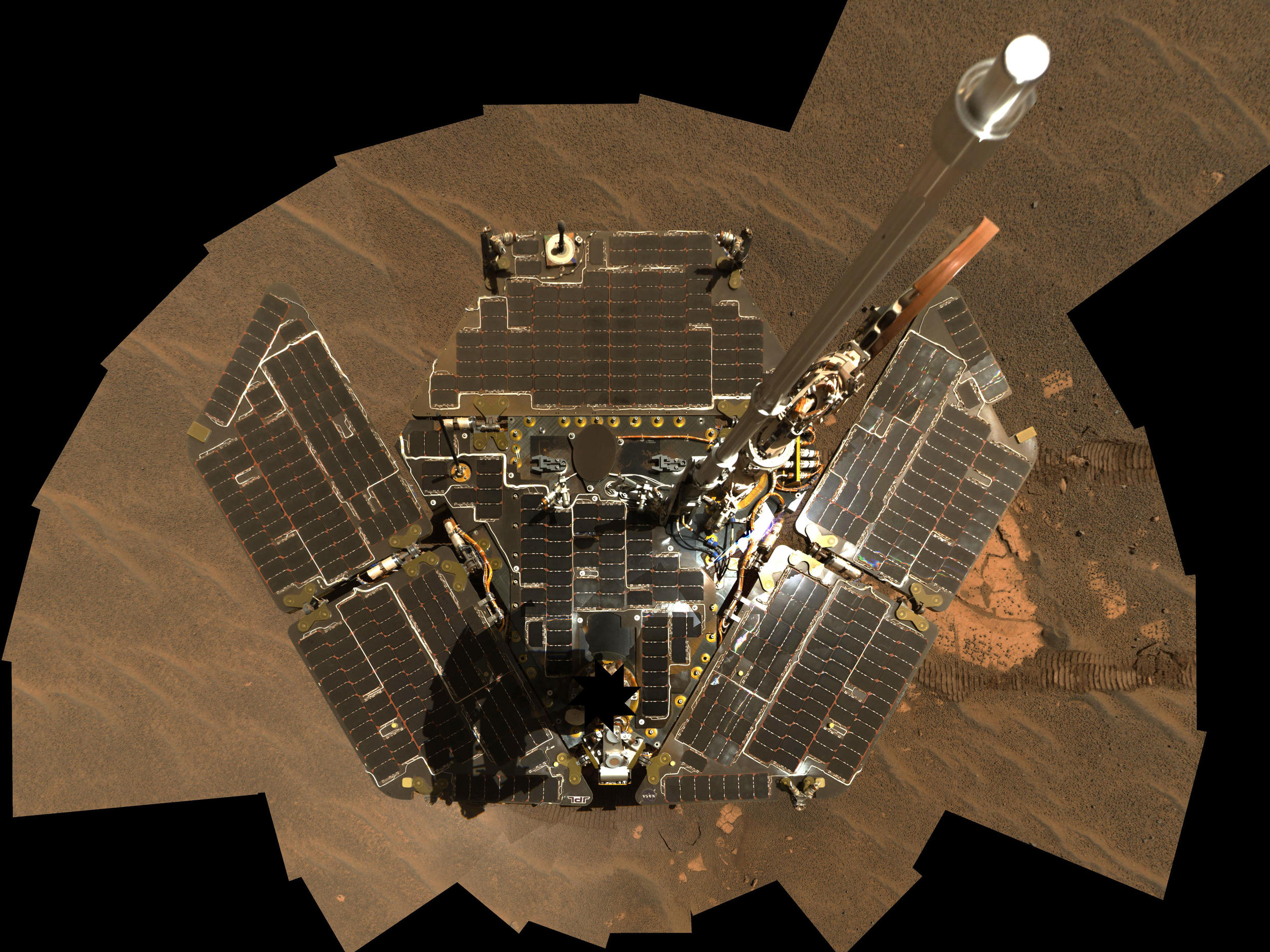
Evolving the flat, square solar panel from the Sojourner rover on the 1996 Mars Pathfinder mission into more powerful solar "wings"
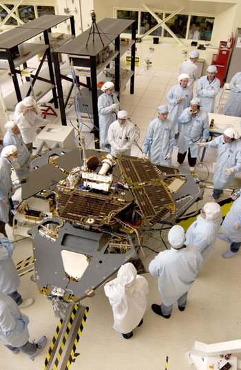
This
image is a bird's eye view of a group of engineers and technicians who
are working on placing solar cells on the Spirit rover's 'wings' in
JPL's spacecraft assembly facility.
Download full image ›
Download full image ›
Another innovation for the rovers is the addition of Triple Junction Gallium Arsenides. These three-layered solar cells made their first trip to Mars aboard the twin rovers. Used on NASA's Deep Space 1 mission, these cells are able to absorb more sunlight than the single cell versions sent on Sojourner. The solar cells are stacked in three layers on the rover's solar arrays and, because they absorb more sunlight, can supply more power to the rover's re-chargeable lithium batteries.
The Sojourner rover on the Pathfinder mission carried one 40-amp-hour lithium battery. The Mars Exploration Rovers carry two 8-amp-hour lithium batteries. During the rovers' prime missions, their solar arrays were able to produce about 900 watt-hours of energy per martian day, or sol. Well into the extended mission, efforts to drive Spirit and Opportunity strategically through and toward solar-rich areas is providing up to 410 watt-hours per martian sol.
Using solar power limits the places on Mars that landed rover missions can explore. They are restricted to landing and traveling around the equatorial region where they can get enough sunlight to re-energize their batteries. For future missions, NASA is considering alternate power sources to increase the area on Mars that might be studied, opening up the whole planet to exploration.
Mars Exploration Rovers:
Spacecraft
What is the spacecraft?

Spacecraft
Download full image ›
Download full image ›
The spacecraft includes the mechanical units that safely carry and maneuver the rover as it enters the Martian atmosphere and lands on Mars. Once on the surface, like a semi-truck carrying a racecar cross-country, it lowers a ramp to let the rover drive out.

Entry, Descent, & Landing System:
Configuration for entry into the Martian atmosphere. Includes the aeroshell (the heatshield and backshell), the parachute, the airbags, and a lander structure.
Rover:
A wheeled vehicle with science instruments for discoveries on the Martian surface.
The spacecraft design for the Mars Exploration Rover mission is largely based on the successful Mars Pathfinder system for entry, descent, and landing. The rover design is based on the Athena Rover on the previously cancelled Mars 2001 lander mission.
How much does the spacecraft weigh?
Each system has a total launch mass of 1,063 kilograms (2,343 pounds). The mass of each primary part of the spacecraft is as follows:| Allocated Mass in kg (lbs) |
Cumulative Mass in kg (lbs) |
|
|---|---|---|
| Rover | (408 lbs) |
(408 lbs) |
| Lander | (767 lbs) |
(1,175 lbs) |
| Backshell / Parachute | (742 lbs) |
(1,636 lbs) |
| Heat Shield | (172 lbs) |
(1,808 lbs) |
| Cruise Stage | (425 lbs) |
(2,233 lbs) |
| Propellant | (110 lbs) |
(2,343 lbs) |
How Drone Solutions Are Powering the Future of Solar Energy
We explore how resources such as solar energy can benefit from the technology of the future, specifically drone based solutions. We’ll explore how each stage of setting up solar power stations can use drone solutions to bring light to the future.The use of drone solutions can prevent and pre-emptively predict the spread of degradation of solar panels and determine which panels need cleaning or repair. Drone solutions that detect hotspots and drop in energy outputs are able not only to increase the PV plant efficiency but also reduce the cost of its maintenance since they practically require any human participation in work. Drone solutions in this way help teams pinpoint problem areas and fast-track repairs to keep solar operation running at peak efficiency and reduce the number of manpower per MW needed for the upkeep in performance.

Future of drones : beyond the horizon
Drone solutions have unimaginable possibilities to revolutionise energy industries by automating the way we plan, build and maintain sustainable energy sources, and completing tasks faster, cheaper, and more safely than humans ever could, or even performing functions that could never have been dreamed of in the first place without drone technology.Solar energy’s overall share of global power generation remains low, but is about to witness a major increase with the onset of drones into the sector. With technologies like thermal imagery and 3D modelling, drone solutions are set to cause a major paradigm shift as a growing number of companies are accommodating drone based outputs into their workflows, as the world shifts to new resources and companies are built to harness the resources so will solutions that enable this shift, stay tuned to understand in even more depth how drone solutions can be used in each stage of the project lifecycle.
🔝 STAR LIGHT ENERGY⦽
Starlight (interstellar probe) Project Starlight is a research project of the University of California, Santa Barbara to develop a fleet of laser beam-propelled spacecraft and sending them to a star neighboring the Solar System, potentially Alpha Centauri. The project aims to send organisms on board the spacecraft.
Starlight aims to accelerate the spacecrafts with powerful lasers, a method the project refers to as DEEP-IN (Directed Energy Propulsion for Interstellar Exploration), thus allowing them to reach stars near the Solar System in a matter of years, in contrast to traditional propulsion methods which will require thousands of years. Each spacecraft will be the size of a DVD disc and will be powered by plutonium. They will fly at one-fifth of the speed of light, and in the case of Alpha Centauri, it will arrive after traveling more than twenty years from Earth. Starlight is a program of the Experimental Cosmology Group of University of California, Santa Barbara (UCSB), and has received funding from NASA. In 2015, the NASA Innovative Advanced Concepts (NIAC) selected DEEP-IN as a phase-1 project.
One goal of Starlight is to send terrestrial organisms along with the spacecraft, and observe how the interstellar environment and extreme acceleration affects them. This effort is known as Terrestrial Biomes in Space, and the lead candidate is Caenorhabditis elegans, a minuscule nematode. The organism will spend most of the voyage in a frozen state, and once the spacecraft approaches its target they will be thawed by heat from the onboard plutonium. Following their revival, the organisms will be monitored by various sensors, and the data they produce will be sent back to Earth. C. elegans have been used extensively in biological research as a model organism, owing to the fact that the worm has one of the least number of cells for an animal possessing a nervous system. A backup option for C. elegans are tardigrades, micro-animals that are known for their resilience to various conditions lethal to other animals, such as the vacuum environment of space and strong doses of ionizing radiation.
Planetary protection
NASA's funding does not cover the Terrestrial Biome in Space portion of Starlight, as the experiment may potentially contaminate exoplanets.Interstellar travel is crewed or uncrewed travel between stars or planetary systems. Interstellar travel would be much more difficult than interplanetary spaceflight. Whereas the distances between the planets in the Solar System are less than 30 astronomical units (AU), the distances between stars are typically hundreds of thousands of AU, and usually expressed in light-years. Because of the vastness of those distances, practical interstellar travel based on known physics would need to occur at a high percentage of the speed of light, allowing for significant travel times, at least decades to perhaps millennia or longer.
The speeds required for interstellar travel in a human lifetime far exceed what current methods of spacecraft propulsion can provide. Even with a hypothetically perfectly efficient propulsion system, the kinetic energy corresponding to those speeds is enormous by today's standards of energy development. Moreover, collisions by the spacecraft with cosmic dust and gas can produce very dangerous effects both to passengers and the spacecraft itself.
A number of strategies have been proposed to deal with these problems, ranging from giant arks that would carry entire societies and ecosystems, to microscopic space probes. Many different spacecraft propulsion systems have been proposed to give spacecraft the required speeds, including nuclear propulsion, beam-powered propulsion, and methods based on speculative physics.
For both crewed and uncrewed interstellar travel, considerable technological and economic challenges need to be met. Even the most optimistic views about interstellar travel see it as only being feasible decades from now. However, in spite of the challenges, if or when interstellar travel is realized, a wide range of scientific benefits is expected.
Most interstellar travel concepts require a developed space logistics system capable of moving millions of tonnes to a construction / operating location, and most would require gigawatt-scale power for construction or power (such as Star Wisp or Light Sail type concepts). Such a system could grow organically if space-based solar power became a significant component of Earth's energy mix. Consumer demand for a multi-terawatt system would automatically create the necessary multi-million ton/year logistical system


Theoretical concepts
Faster-than-light travel

Artist's depiction of a hypothetical Wormhole Induction Propelled Spacecraft, based loosely on the 1994 "warp drive" paper of Miguel Alcubierre.
It is also debatable whether faster-than-light travel is physically possible, in part because of causality concerns: travel faster than light may, under certain conditions, permit travel backwards in time within the context of special relativity. Proposed mechanisms for faster-than-light travel within the theory of general relativity require the existence of exotic matter and it is not known if this could be produced in sufficient quantity.
Alcubierre drive
In physics, the Alcubierre drive is based on an argument, within the framework of general relativity and without the introduction of wormholes, that it is possible to modify spacetime in a way that allows a spaceship to travel with an arbitrarily large speed by a local expansion of spacetime behind the spaceship and an opposite contraction in front of it. Nevertheless, this concept would require the spaceship to incorporate a region of exotic matter, or hypothetical concept of negative mass.Artificial black hole
A theoretical idea for enabling interstellar travel is by propelling a starship by creating an artificial black hole and using a parabolic reflector to reflect its EINSTEIN Gravitation 5 dimension . Although beyond current technological capabilities, a black hole star ship offers some advantages compared to other possible methods. Getting the black hole ( Long Transverse ) to act as a power source and engine also requires a way to convert the Hawking radiation into energy and thrust. One potential method involves placing the hole at the focal point of a parabolic reflector attached to the ship, creating forward thrust. A slightly easier, but less efficient method would involve simply absorbing all the gamma radiation heading towards the fore of the ship to push it on wards, and let the rest shoot out the back._________________________________________________________________________________

Gen. Mac Tech making 2 directions into 1 space fighter aircraft energy technique
_________________________________________________________________________________
jQuery File upload progress bar
BalasHapusGoogle Street View API Example
How to generate QR Code in PHP
PHP code to send email using SMTP
Get Visitor's location and TimeZone
select/deselect all checkboxes using JS
Fibonacci Series Program in PHP
Detect Mobile Devices in PHP
Convert MySQL to JSON using PHP