Xi . RADAR and LASER
A radar detector is an electronic device used by motorists to detect if their speed is being monitored by police or law enforcement using a radar gun. Most radar detectors are used so the driver can reduce the car's speed before being ticketed for speeding. In general sense, only emitting technologies, like doppler RADAR, or LIDAR can be detected. Visual speed estimating techniques, like ANPR or VASCAR can not be detected in daytime, but technically vulnerable to detection at night, when IR spotlight is used. There are no reports that piezo sensors can be detected. LIDAR devices require an optical-band sensor, although many modern detectors include LIDAR sensors. Most of today's radar detectors detect signals across a variety of wavelength bands: usually X, K, and Ka. In Europe the Ku band is common as well. The past success of radar detectors was based on the fact that radio-wave beam can not be narrow-enough, so the detector usually senses stray and scattered radiation, giving the driver time to slow down. Based on a focused laser-beam, LIDAR technology does not suffer this shortcoming; however it requires precise aiming. Modern police radars incorporate formidable computing power, producing a minimum number of ultra-short pulses, reusing wide beams for multi-target measurement, which renders most detectors useless. But, mobile Internet allows GPS navigation devices to map police radar locations in real-time. These devices are also often called "radar detectors", while not necessary carrying an RF sensor.

One device law enforcement use to measure the expected speed of a moving vehicle is doppler radar, which uses the doppler effect to measure the relative speed of a vehicle. Doppler radar works by beaming a radio wave at a vehicle to then measure the expected change in frequency of the reflected wave (that bounces off the vehicle). Law enforcement often employs doppler radar via hand-held radar guns, from vehicles, or from fixed objects such as traffic signals.
Radar detectors use a superheterodyne receiver to detect these electromagnetic emissions from the gun, and raise an alarm to notify the motorist when a transmission is detected. False alarms can occur however due to the large number of devices, such as automatic door openers (such as the ones at supermarkets), speed signs, and adaptive cruise control, that operate in the same part of the electromagnetic spectrum as radar guns.
In recent years , some radar detectors have added GPS technology. This allows users to manually store the locations where police frequently monitor traffic, with the detector sounding an alarm when approaching that location in the future (this is accomplished by pushing a button and doesn't require coordinates to be entered). These detectors also allow users to manually store the coordinates of sites of frequent false alarms, which the GPS enabled detector will then ignore. The detector can also be programmed to mute alerts when traveling below a preset speed, limiting unnecessary alerts. Some GPS enabled detectors can download the GPS coordinates of speed monitoring cameras and red-light cameras from the Internet, alerting the driver that they are approaching the camera.
Counter Technology
Radar guns and detectors have evolved alternately over time to counter each other's technology in a form of civilian electronic "warfare". For example, as new frequencies have been introduced, radar detectors have initially been "blind" to them until their technology, too, has been updated. Similarly, the length of time and strength of the transmissions have been lowered to reduce the chance of detection, which in turn has resulted in more sensitive receivers and more sophisticated software counter technology. Lastly, radar detectors may combine other technologies, such as GPS-based technology with a point of interest database of known speed trapping locations, into a single device to improve their chances of success.
Radar detector detectors
The superheterodyne receiver in radar detectors has a local oscillator that radiates slightly, so it is possible to build a radar-detector detector, which detects such emissions (usually the frequency of the radar type being detected, plus about 10 MHz). The VG-2 Interceptor was the first device developed for this purpose, but has since been eclipsed by the Spectre III and Spectre Elite. This form of "electronic warfare" cuts both ways - since detector-detectors use a similar superheterodyne receiver, many early "stealth" radar detectors were equipped with a radar-detector-detector-detector circuit, which shuts down the main radar receiver when the detector-detector's signal is sensed, thus preventing detection by such equipment. This technique borrows from ELINT surveillance countermeasures. In the early 1990s, BEL-Tronics, Inc. of Ontario, Canada (where radar detector use is prohibited in most provinces) found that the local oscillator frequency of the detector could be altered to be out of the range of the VG-2 Interceptor (probably by using two LO stages such that neither is near the RF frequency). This resulted in detector manufacturers responding by changing their local oscillator frequency. Today, practically every radar detector on the market is immune to the VG-2 Interceptor.. The VG-2 is no longer in production and radar detectors immune to the Spectre Elite are available.Radar scrambling
It is illegal in many countries to sell or possess any products that actively transmit radar signals intended to jam radar equipment In the United States, actively transmitting on a frequency licensed by the Federal Communications Commission (FCC) without a licence is a violation of FCC regulations, which may be punishable by fines up to $10,000 and/or up to one year imprisonment .LIDAR DETECTION

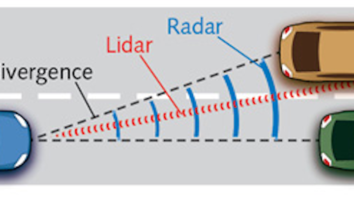
Newer speed detection devices use pulsed laser light, commonly referred to as LIDAR, rather than radio waves. Radar detectors, which detect radio transmissions, are unable to detect the infrared light emitted by LIDAR guns, so a different type of device called a LIDAR detector is required. However, LIDAR detection is not nearly as effective as radar detection because the output beam is very focused. While radar's radio waves can expand to 85 feet (26 m) across at 1,000 feet (300 m) from their source, LIDAR's light beam diffuses to only about 6 feet (1.8 m) A police officer targeting a car will most likely aim for the center mass or headlight of the vehicle and, because radar detectors are mounted on the windshield away from the beam's aim, they may not alert at all. With such a focused beam, an officer using a LIDAR gun can target a single car in close proximity to others at ranges of up to 3,000 feet (910 m). This has resulted in some manufacturers producing LIDAR jammers. Unlike those of radar, LIDAR's frequencies and use are not controlled by the FCC. These jammers attempt to confuse police LIDAR into showing no speed on the display. They are often successful, and therefore many LIDAR manufacturers produce LIDAR guns that have "jam codes" that show when they are being jammed. They will work against some LIDAR jammers, but not all. In spite of this, police can often tell when they are being jammed when they see no reading on their LIDAR gun. Many jammer-equipped motorists try to counter this by reducing their speed to legal limits before turning off their jammer equipment, a technique known as "kill the equipment", referred to as "JTK" or "Jam to Kill." Officers can often detect this by observing that their LIDAR equipment is unable to lock in a speed properly, along with visual indication of sudden deceleration of the targeted vehicle. They will then pull the offending vehicle over and look for LIDAR jammers on the front of the vehicle, potentially ticketing the motorist with an obstruction of justice charge. Some states also have laws against jamming of police radar or LIDAR: California, Colorado, Illinois, Minnesota, Oklahoma, Tennessee, Texas, Utah and Virginia.In these states, the penalties can be severe.
Despite the advent of LIDAR speed detection, radar remains more prevalent because of its lower price and the amount of radar equipment already in service. In addition, proper use of LIDAR equipment requires the officer to remain stationary in order to beam a very precise signal.
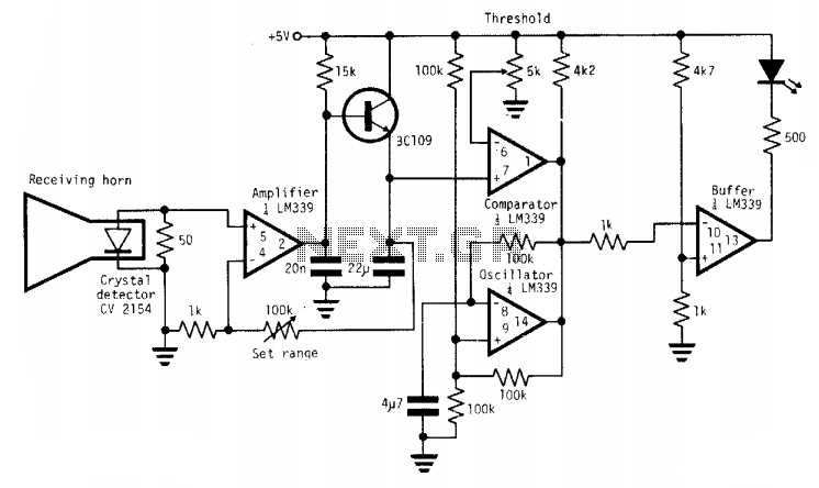
Radar Detector Laser Jammer Schematic
LASER HARP
JAMMER CIRCUIT
Electronics
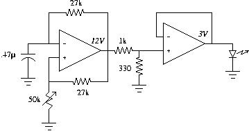
The laser emitter was extracted from a normal laser pointer we bought at Fry's. The emitter is driven using a square oscillator going between -3V and +3V. The output of the oscillator is fed through a buffer since we don't know very much about the emitter (how much current it draws, what its resistance is, etc). The frequency of the oscillator can be adjusted to make the laser pulsing visible.
The detector circuit consists of 2 main parts: a voltage multiplier and an optical sensor ( NTE3034A, a T-NPN photo-darlington, also from Fry's). The sensor will draw current when light falls on it. It is pretty insensitive to ambient light and detects visible and near-infrared light. When we point the modulated laser light from the emitter to it, we get a square wave signal out of the emitter pin of the sensor (we connect the collector to +5V). We need to adjust this voltage such that it goes between 0 and +2V. The square wave detected by the sensor is fed to an AD633, a voltage multiplier. The reference voltage for this 0-2V square wave is 1V, such that the multiplier actually sees a square wave from -1V to +1V. If we now feed the other input of the multiplier with the signal we used to modulate the emitter (we scale it to be between -5V and +5V, using a voltage divider), we will get a +0.5V DC signal out (the multiplier multiplies signals and divides the result by 10V) only if the frequencies of the input signals are equal. If there are small phase differences between the signals, we can get short voltage drops in the DC signal, which we counter by lowpass-filtering the output of the multiplier (160Hz cutoff frequency, since you can't really move your hand that fast :-) The output of the lowpass filter then goes to a positive gain amplifier to create a +5V DC signal, which we can feed directly into the basic stamp without using an A/D (the button command will do just fine).
Radar Detector Laser Jammer Schematic
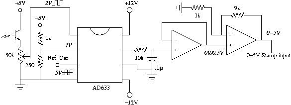
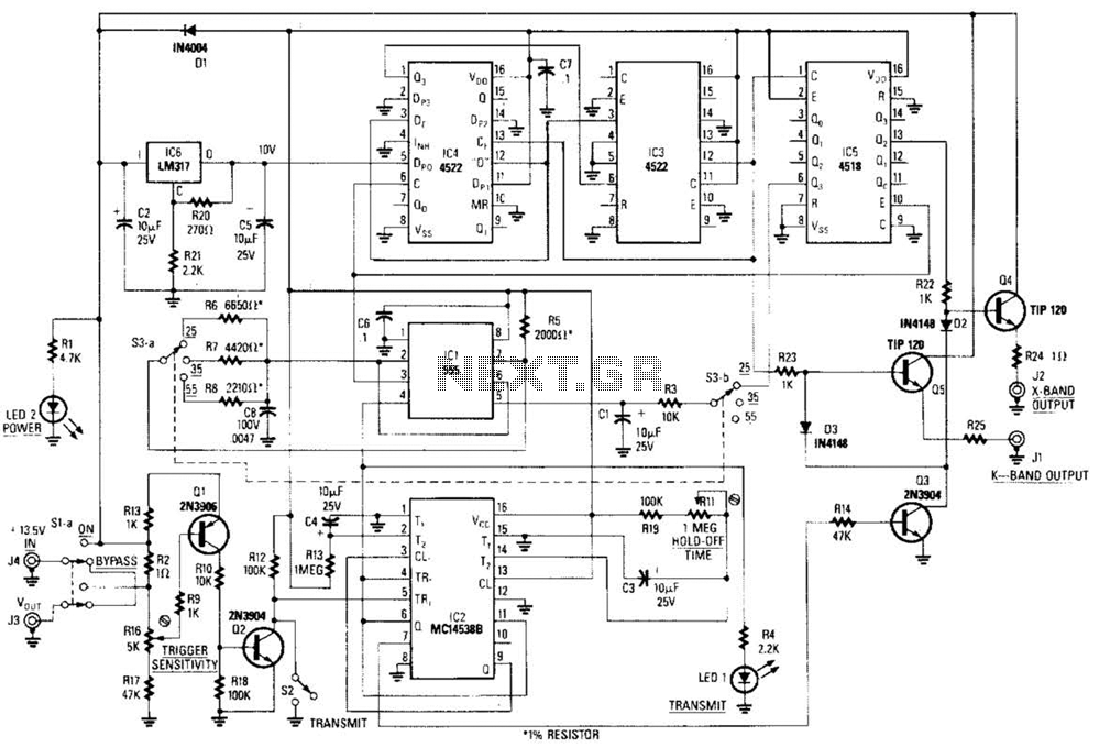
RADAR CALIBRATOR CIRCUIT
_________________________________________________________________________________
This circuit is basically a system that generates a pulsed modulation signal for a Gunn diode microwave oscillator. Several speed settings are preset (S3 a and b). A 555 timer is used with a frequency divider chain to produce Doppler shift equivalents of 25, 35, and 55 rnph,

Radar Detector, Microwave Sensor Module Radar/Laser Detector with 360 Degree Detection, CDM324 .

laser breathalyzer, for drive-by DUI enforcement
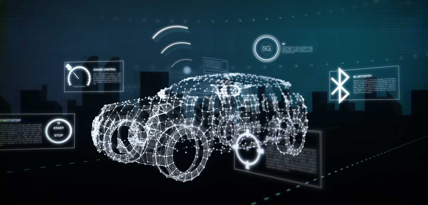
SELF DRIVING CAR
So, how do self-driving cars work? we have a basic concept of e- dynamic control .
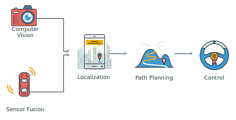
Self-driving cars have five core components:
- Computer Vision
- Sensor Fusion
- Localization
- Path Planning
- Control
Sensor fusion is how we integrate data from other sensors, like radar and lasers—together with camera data—to build a comprehensive understanding of the vehicle’s environment. As good as cameras are, there are certain measurements — like distance or velocity — at which other sensors excel, and other sensors can work better in adverse weather, too. By combining all of our sensor data, we get a richer understanding of the world.
Localization is how we figure out where we are in the world, which is the next step after we understand what the world looks like. We all have cellphones with GPS, so it might seem like we know where we are all the time already. But in fact, GPS is only accurate to within about 1–2 meters. Think about how big 1–2 meters is! If a car were wrong by 1–2 meters, it could be off on the sidewalk hitting things. So we have much more sophisticated mathematical algorithms that help the vehicle localize itself to within 1–2 centimeters.
Path planning is the next step, once we know what the world looks like, and where in it we are. In the path planning phase, we chart a trajectory through the world to get where we want to go. First, we predict what the other vehicles around us will do. Then we decide which maneuver we want to take in response to those vehicles. Finally, we build a trajectory, or path, to execute that maneuver safely and comfortably.
__
Xi and Xie Counter and Register in electronic for response time
In the process of calculation, measurement and observation of a moving object we need a digital and analog counter concept and addressing concept or commonly called a register, let's look at the concept and examine:
COUNTER ROLLING ( CONTROL )
1. Introduction
An enumerator is a sequence of flip-flops that transmits from an output condition one to the other output conditions in order to respond to a situation (set of input signals).
There are two types of enumerators, namely asynchronous counter and synchronous counter.
2 Asynchronous enumerators
This enumerator is also called a non-simultaneous enumerator or ripple counter. Where the clock pin does not all get directly from the source but serialized to the other. And so on, the more flip-flops used will be the greater the clock delay that occurs. The lowest bit can be called LSB with the biggest one called MSB. This enumerator has a count of down and up in its arrangement.
3 Binary Enumerators
This enumerator is an Asynchronous Counter that counts up from 0 to 15.


Simple - up down counter
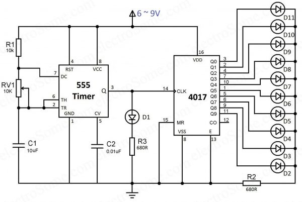
LED Chaser using 4017 Counter
SHIFT REGISTER ( Addressing Code )
 |
||||
What is Shift Register:
Shift Registers are sequential logic circuits,
capable of storage and transfer of data. They are made up of Flip Flops
which are connected in such a way that the output of one flip flop
could serve as the input of the other flip-flop, depending on the type
of shift registers being created.

Shift registers are basically a
type of register which have the ability to transfer (“shift”) data.
Registers are generically storage devices which are created by
connecting a specific number of flip flops together in series and the
amount of data (number of bits) which can be stored by the register is
always directly proportional to the number of flip flops, as each flip
flop is capable of storing only one bit at a time. When the
flip-flops in a register are connected in such a way that the output of
one flip flop, becomes the input of the other, a shift register is
created.

D Flip-Flop 
D- Flip Flop Truth Table
Flip Flops are devices with an operation similar to that of a latch. It can be referred to as a bistable vibrator
which can move between two states (0 or 1) and is capable of storing
data in bits. New data is read into a flip flop with each clock cycle
and the previous data sent at the output. This however depends on the
kind of flip flop, as the Input, Output, and clock cycle relationship
between flip flops vary. There are different kinds of flip flops, but
the most commonly used in the creation of shift registers are the D (Delay)-flip flops.
For the operation of the D flip flops which makes
them so desirable for shift registers, Whenever there is a change on the
clock of a D flip flop (either rising or falling edge, depending on the
specifications of the flip flop). The data at the output “Q” becomes the same data as the one at the input “D”. The Output “Q”
of the flip flop will stay at that value until the next clock cycle,
where it will then change again to the value(High or low, 1 or 0) at the
input.
Types of Shift Registers
Shift registers are categorized into types majorly by their mode of operation, either serial or parallel.
There are six (6) basic types of shift registers
which are listed below although some of them can be further divided
based on direction of data flow either shift right or shift left.
1. Serial in – Serial out Shift Register (SISO)
2. Serial In – Parallel out shift Register (SIPO)
3. Parallel in – Parallel out Shift Register (PIPO)
4. Parallel in – Serial out Shift Register (PISO)
5. Bidirectional Shift Registers
6. Counters1. Serial in - Serial out Shift Registers
Serial in – Serial out shift registers are shift
registers that streams in data serially (one bit per clock cycle) and
streams out data too in the same way, one after the other.

A simple serial in – serial Out 4-bit shift register is shown above, the register consists of 4 flip flops and the breakdown of how it works is explained below;
On startup, the shift register is first cleared,
forcing the outputs of all flip flops to zero, the input data is then
applied to the input serially, one bit at a time.
There are two basic ways of shifting data out through a shift register;
- Non-destructive Readout
- Destructive Readout
- Non-Destructive Readout
Non - Destructive readout based, shift registers always have a read/write mode of operation with an extra line added to allow the switch between the read and write operational modes.
When the device is in the “write” operational
mode, the shift register shifts each data out one bit at a time behaving
exactly like the destructive readout version and data is thus lost, but
when the operational mode is switched to “read”, data which are shifted
out at the input goes back into the system and serve as input to the
shift register. This helps ensure that the data stays longer (as long as
it stays in read mode)
- Destructive Readout
For destructive readouts, the data is
completely lost as the flip flop just shifts the information through.
Assuming for the 4-bit shift register above, we want to send the word
“1101”. After clearing the shift register, the output of all the flip
flops becomes 0, so during the first clock cycle as we apply this data
(1101) serially, the outputs of the flip flops look like the table
below.
First clock cycle:
| FF0 | FF1 | FF2 | FF3 |
| 1 | 0 | 0 | 0 |
Second clock cycle:
| FF0 | FF1 | FF2 | FF3 |
| 0 | 1 | 0 | 0 |
Third Clock Cycle:
| FF0 | FF1 | FF2 | FF3 |
| 1 | 0 | 1 | 0 |
Fourth Clock Cycle:
| FF0 | FF1 | FF2 | FF3 |
| 1 | 1 | 0 | 1 |
2. Serial in – Parallel out Shift Register
The second type of shift register we will be
considering is the Serial in – Parallel out shift register. These types
of shift registers are used for the conversion of data from serial to
parallel. The data comes in one after the other per clock cycle and can
either be shifted and replaced or be read off at each output.
This means when the data is read in, each read in bit becomes available
simultaneously on their respective output line (Q0 – Q3 for the 4-bit
shift register shown below).
A 4-bits serial in – Parallel out shift register is illustrated in the Image below.

A table showing how data gets shifted out of
serial in –parallel out 4 bit shift register is shown below, with the
data in as 1001.
| Clear | FF0 | FF1 | FF2 | FF3 |
| 1001 | 0 | 0 | 0 | 0 |
| 1 | 0 | 0 | 0 | |
| 0 | 1 | 0 | 0 | |
| 0 | 0 | 1 | 0 | |
| 1 | 0 | 0 | 1 |
A good example of the serial in – parallel out shift register is the 74HC164 shift register, which is an 8-bit shift register.
The device features two serial data inputs (DSA
and DSB), eight parallel data outputs (Q0 to Q7). Data is entered
serially through DSA or DSB and either input can be used as an active
HIGH enable for data entry through the other input. Data is shifted on
the LOW-to-HIGH transitions of the clock (CP) input. A LOW on the master
reset input (MR) clears the register and forces all outputs LOW,
independently of other inputs. Inputs include clamp diodes. This enables
the use of current limiting resistors to interface inputs to voltages
in excess of VCC.

3. Parallel in – Serial out Shift Register
For this type of shift register, the data is supplied in parallel, for example consider the 4-bit shift register shown below.

This register can be used to store and shift a
4-bit word, with the write/shift (WS) control input controlling the mode
of operation of the shift register. When the WS control line is low
(Write Mode), data can be written and clocked in via D0 to D3. To shift
the data out serially, the WS control line is brought HIGH (Shift mode),
the register then shifts the data out on clock input.
A good example of a parallel in – serial out shift register is the 74HC165 8-bit shift register although it can also be operated as a serial in – serial out shift register.
The device features a serial data input (DS),
eight parallel data inputs (D0 to D7) and two complementary serial
outputs (Q7 and Q7’). When the parallel load input (PL) is LOW the data
from D0 to D7 is loaded into the shift register asynchronously. When PL
is HIGH data enters the register serially at DS. When the clock enable
input (CE) is LOW data is shifted on the LOW-to-HIGH transitions of the
CP input. A HIGH on CE will disable the CP input. Inputs are overvoltage
tolerant to 15 V. This enables the device to be used in HIGH-to-LOW
level shifting applications.
The functional diagram of the shift register is shown below;

74HC165 Shift Register Functional Diagram
The timing diagram for the system is as shown in the image below;

74HC165 timing diagram
4. Parallel in – Parallel out shift register
For parallel in – parallel out shift register, the
output data across the parallel outputs appear simultaneously as the
input data is fed in.

4 Bits PIPO Shift Register
The input data at each of the input pins from D0
to D3 are read in at the same time when the device is clocked and at the
same time, the data read in from each of the inputs is passed out at
the corresponding output (from Q0 to Q3).
The 74HC195 shift register is a multipurpose shift register
which is capable of working in most of the modes described by all the
types we have discussed so far especially as a parallel in – parallel
out shift register.
5. Bidirectional Shift Registers
Shift registers could either perform right or left
data shift, or both depending on the kind of shift register and their
configuration. In right shift operations, the binary data is divided by
two. If this operation is reversed, the binary data gets multiplied by
two. With suitable application of combinational logic, a serial shift
register can be configured to perform both operation.
Consider the 4-bits register in the image below. A
couple of NAND gates are configured as OR gates and are used to control
the direction of shift, either right or left.

The control line left/write is used to determine the direction to which data is shifted, either right or left.
The 74HC194 Bi-direction shift register is a good example.
The register can operate in all the modes and variations of serial and
parallel input or output. The functional diagram of the 74HC194
highlighting the control line, clock, input and output pins is shown
below.
 74HC147
The timing diagram of the device is also shown below. It will better
help you understand how the control line controls the actions of the
register.

6. Counters
Counters, sometimes called rotate shift register
are basically shift registers with their outputs fed back into the
device as inputs in such a way that it creates a particular pattern.
These kinds of registers are referred to as counters because of the
pattern and sequence they exhibit.
This most popular type of shift register counters are the ring counters.
Ring Counter
Ring counters are basically a type of counter in
which the output of the most significant bit is fed back as an input to
the least significant bit. A 4-bit ring counter is illustrated in the
diagram below using D flip flops.

4 BIT Ring Counter
When the clock pulse is applied, the output of
each stage is shifted to the next one, and the cycle keeps going. When
clear is turned high, all the flip flops except the first one (which
gets set to 1) is reset to zero.
Applications of Shift registers
Shift registers are used in a lot of applications some of which are;
1. Parallel to serial conversion,
where they are used to reduce the number of wires, or lines needed for
communication between two devices, since serial communication generally
require just two wires compared to parallel which depends on the number
of bits being sent.
2. IO expansion for microcontrollers.
In modern day electronics, microcontrollers IO pins are referred to as
real estates and one needs as much as possible for certain application
like turning on 100 leds or reading 100 reed switches with something
like an Arduino or the Atmeg328p microcontroller. For example, the
circuit diagram below illustrates how a serial to parallel shift
register can be used to control 8 LEDs, using just three of the
microcontrollers IO pins.

Reducing the required MCU’s IO pins using a Shift Register
3. They are used in state registers which are used in sequential devices.
Like a finite memory machine, the next state of the device is always
determined by shifting and inserting a new data into the previous
position.
4. One other main application is found in Time delays.
Shift registers are used for time delay in devices, with the time being
adjusted by the clock, or increased by cascading shift registers or
reduced by taking the output from a lower significant bit.
The time delay is usually calculated using the formula;
t = N * (1 / fc)
N is the number of flip flop stage at which the
output is taken, Fc is the frequency of the clock signal and t which is
the value being determined is the amount of time for which the output
will be delayed.
When selecting a shift register
for a particular task because of the wide range and type its important
to select one that matches your particular need, considering things
like, the mode of operation, the bit size (number of flip flops), right
or left or bidirectional etc.
Some of the most popular shift registers are;
- 74HC 194 4-bit bidirectional universal shift register
- 74HC 198 8-bit bidirectional universal shift register
- 74HC595 Serial-In-Parallel-Out shift register
- 74HC165 Parallel-In-Serial-Out shift register
- IC 74291 4-bit universal shift register, binary up/down counter, synchronous.
- IC 74395 4-bit universal shift register with three-state outputs.
- IC 74498 8-bit bidirectional shift register with parallel inputs and three-state outputs.
- IC 74671 4-bit bidirectional shift register.
- IC 74673 16-bit serial-in serial-out shift register with output storage registers.
- IC 74674 16-bit parallel-in serial-out shift register with three-state outputs.
Xi Xie Puc DIGITAL CAMERA
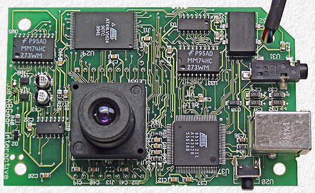
Electronics Camera
They store your money. They monitor your heartbeat. They carry the sound of your voice into other people's homes. They bring airplanes into land and guide cars safely to their destination—they even fire off the airbags if we get into trouble. It's amazing to think just how many things "they" actually do. "They" are electrons: tiny particles within atoms that march around defined paths known as circuits carrying electrical energy. One of the greatest things people learned to do in the 20th century was to use electrons to control machines and process information. The electronics revolution, as this is known, accelerated the computer revolution and both these things have transformed many areas of our lives. But how exactly do nanoscopically small particles .Electronics is a much more subtle kind of electricity in which tiny electric currents (and, in theory, single electrons) are carefully directed around much more complex circuits to process signals (such as those that carry radio and television programs) or store and process information. Think of something like a microwave oven and it's easy to see the difference between ordinary electricity and electronics. In a microwave, electricity provides the power that generates high-energy waves that cook your food; electronics controls the electrical circuit that does the cooking.
Analog and digital electronics

Photo: Digital technology: Large digital clocks like this are quick and easy for runners to read.
There are two very different ways of storing information—known as analog and digital. It sounds like quite an abstract idea, but it's really very simple. Suppose you take an old-fashioned photograph of someone with a film camera. The camera captures light streaming in through the shutter at the front as a pattern of light and dark areas on chemically treated plastic. The scene you're photographing is converted into a kind of instant, chemical painting—an "analogy" of what you're looking at. That's why we say this is an analog way of storing information. But if you take a photograph of exactly the same scene with a digital camera, the camera stores a very different record. Instead of saving a recognizable pattern of light and dark, it converts the light and dark areas into numbers and stores those instead. Storing a numerical, coded version of something is known as digital.
Electronic equipment generally works on information in either analog or digital format. In an old-fashioned transistor radio, broadcast signals enter the radio's circuitry via the antenna sticking out of the case. These are analog signals: they are radio waves, traveling through the air from a distant radio transmitter, that vibrate up and down in a pattern that corresponds exactly to the words and music they carry. So loud rock music means bigger signals than quiet classical music. The radio keeps the signals in analog form as it receives them, boosts them, and turns them back into sounds you can hear. But in a modern digital radio, things happen in a different way. First, the signals travel in digital format—as coded numbers. When they arrive at your radio, the numbers are converted back into sound signals. It's a very different way of processing information and it has both advantages and disadvantages. Generally, most modern forms of electronic equipment (including computers, cell phones, digital cameras, digital radios, hearing aids, and televisions) use digital electronics.

Xi Xie Puc Tien _ Feedback Monitoring System
The grid examples of Feedback Monitoring system :
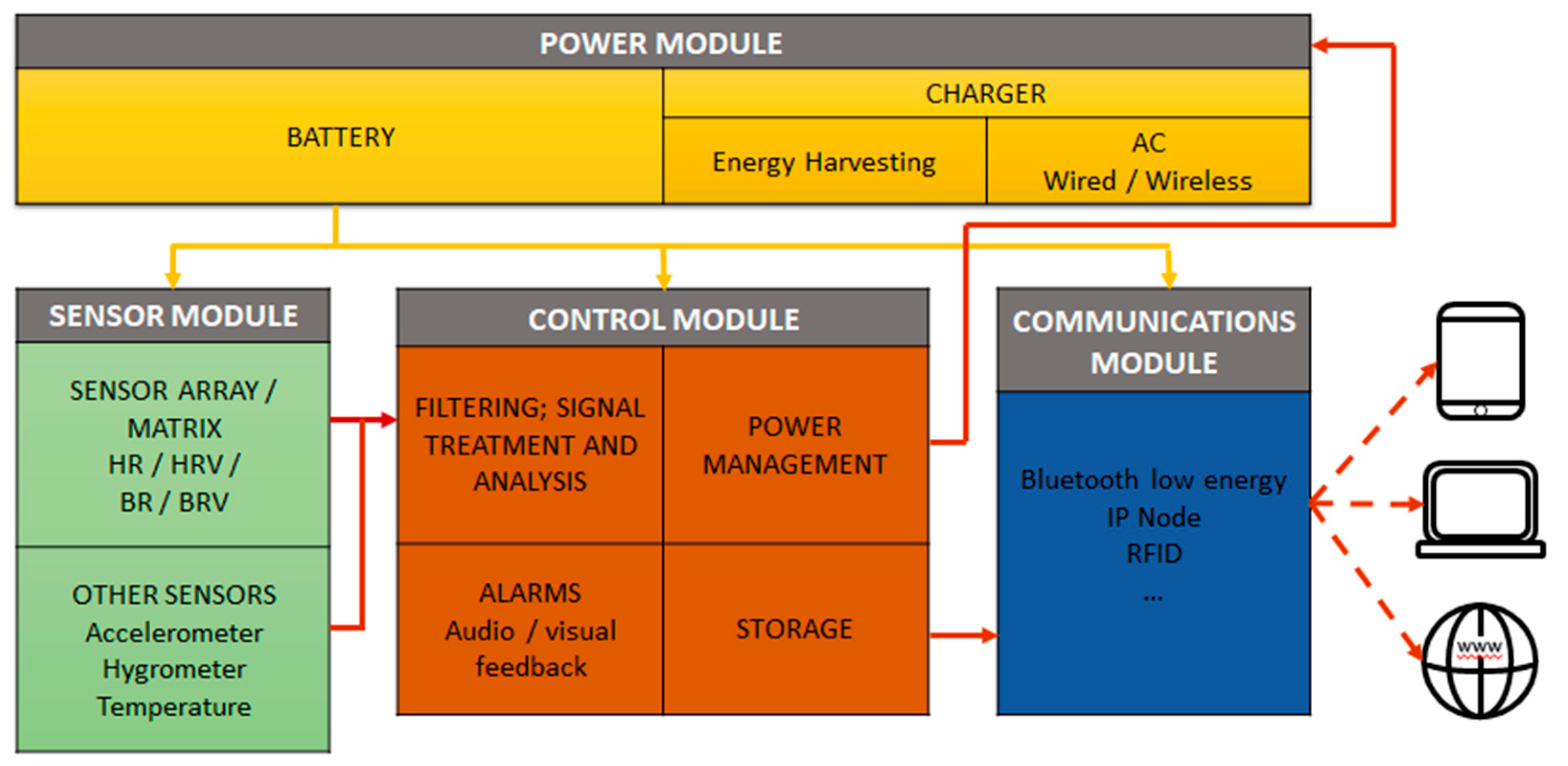
Laboratory mice are used in biomedical research as “models” for studying human disease. These mice may be subject to significant levels of stress during transportation that can cause alterations that could negatively affect the results of the performed investigation. Here, we present the design and realization of a prototypical transportation container for laboratory mice, which may contribute to improved laboratory animal welfare. This prototype incorporates electric potential integrated circuit (EPIC) sensors, which have been shown to allow the recording of physiological parameters (heart rate and breathing rate) and other sensors for recording environmental parameters during mouse transportation. This allows for the estimation of the stress levels suffered by mice. First experimental results for capturing physiological and environmental parameters.

Structure of posture monitoring and feedback system.
portable posture monitoring and feedback system is proposed. System is designed to be unobtrusively used during daily activities and provide alternative solution to traditional bracing used in treatment of scoliosis. System consists of wearable sensor network for posture data acquisition, wireless data transmission and conventional smartphone for data processing, visualization and vibrating feedback generation. Special data acquisition board is designed for data sampling from sensor network and wireless transmission to smartphone. A custom made Android application is used for real time data processing, current posture model visualization, data logging and instantaneous feedback. System was tested for posture monitoring and feedback generation on multiple test subjects. Tests demonstrated systems effectiveness on improving posture related behavior and ability to help subject to hold specific reference posture performing similar task as traditional bracing.

Machine Learning : a feedback loop, the system learns continuously by monitoring the effectiveness of predictions and retraining when needed.

Development of real-time visual monitoring system for vibration effects on fresh concrete
The consolidation of concrete is crucial to ensure the long-term strength and durability of concrete structures.
Although fresh concrete can be consolidated properly via vibration, the
consolidation quality heavily relies on construction workers'
experience. Inexperienced workers tend to under-consolidate or
over-consolidate concrete, resulting in indiscoverable and irreparable
defects. It is necessary to establish a system that can track the
real-time vibration activity and feedback vibration defects to the
inspector and worker. In this paper, a real-time visual monitoring system
of the vibration effects is developed and validated to solve the
under-vibration issues of fresh concrete. The vibration trajectory is
accurately tracked by Global Navigation Satellite System (GNSS). The
vibration duration is calculated based on the alternation time of
vibration status. The data is transmitted and stored in a cloud server
by General Packet Radio Service (GPRS). The radius of action and effective vibration zone are determined by experiments and geometric models. The vibration effects are visualized in three dimensional at the control site. A mobile App
is also developed to visualize defects to the inspector such that
re-vibration can be timely conducted. Field experiments demonstrate that
the tracking accuracy of the system satisfies the demand of
construction applications. Through comparing the defect report of the
system to the results of the nondestructive impact-echo method in a
construction case study, the reliability of the system is verified.

On- Line and Real Monitoring System
Online and real-time monitoring system for remaining service life estimation of automotive transmissions – Application to a manual transmission
introduce cost-efficient lightweight design in transmission engineering is being studied in this paper. This approach is predicated on the implementation in series-production cars of a real-time and online lifetime monitoring system able to estimate the remaining service life of transmission gearwheels, continuously and under operating conditions. The purpose is to develop a simple and application-oriented method, which could serve as an input for control strategies or transmission development. The system is aimed to monitor the transmission loads with the aid of torque identification method and to accumulate the resulting partial damages by each calculation step. This paper proposes the development and the validation of such a system. Firstly, a qualitative and quantitative study of true-to-life drivetrain load cases and their impact on a damage calculation is evaluated. These loads are generated from driving cycles derived from real driving conditions and driver profiles. Owing to these investigations, specification requirements are presented, regarding signal quality, characteristics and counting, and calculation step time. An observer-based torque identification method relying on an Extended Kalman Filter and coupled with a gear recognition function is also addressed. Finally, a global error study for a potential implementation of the method in vehicles is introduced.Xi Xie Puc Tien XO__ Blocking Electronic Signal and Invert signal


Diagram of two input signals consisting of a stronger signal at frequency f1 and a weaker signal at frequency f2 .
In electronics have stages of thinking:
1. analysis and design of an electronic work sequence
2. calculation, measurement and observation of work processes
and a continuous workflow.
3. simulations and controls that continue to improve
4. Products that are progressing both in design and process

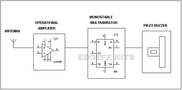
Mobile Phone detector
GPS spoofing attack

_______________________________________________________________________________
_________________________________________________________________________________
Tidak ada komentar:
Posting Komentar