
OFFICE DATABASE COMPONENT ADMINISTRATION CONTACT
some letters and numbers if strung together can become a password and if some passwords are arranged can become a network and a network if it can be arranged into a large system so that a large system comes from data data with letters and numbers adapted into information that uses modern electronic media that is valid and verified. In electronic media data is an address that shows the location of the frequency of sounds, images, movements, signals that can be arranged into important information which means for the overall importance of a larger network system.

Gen. Mac Tech on Zone DIVV 22
I. Computer as like as The Backbone of communication
( The relation Computer with the other Computer )
Computer is a way of interconnection between computer systems and computer devices through strings or without strings (wireless).
How to Communication Data (Data Communications)
Data communication via string may use:
• Electric through copper wire
• Laser through Optical Gentian (fiber optic)
• Electric through copper wire
• Laser through Optical Gentian (fiber optic)
Data communication without strings may use:
• Radio waves (radio waves)
• Microwave (microwave)
• Satellite (satellite)
• Laser
• Radio waves (radio waves)
• Microwave (microwave)
• Satellite (satellite)
• Laser
Data may be transmitted analogously or digitally. Exchange of data from analog to digital domains and vice versa is done by modifiers or codecs (Coder-Decoder).
Data delivery is usually done exclusively. However, the technique of delivering multiple data cues simultaneously is known as multiplexing techniques.
Data delivery is usually done exclusively. However, the technique of delivering multiple data cues simultaneously is known as multiplexing techniques.
The circuit functions can be divided into voice networks and data networks. The current series has merged the two functions to produce integrated networks.
Telecommunications (telecommunications) is a field of study of voice delivery systems by telephone.
Management of the series (network management) encompasses the form (design), installation (installation), and supervision (monitoring) and management (management) of the circuit.
Computer Circuit Components
a computer circuit consists of various components:
• Work stations (workstations): personal computer systems (PCs) or terminals used by users
• Servers: contain software and data stored by the user
• Bridge: connects multiple LANs
• router: connects the LAN to the WAN
• switches: how to connect using circuits that hold multiple connections simultaneously
• Hab (hub): LAN connection support tool to the work station .
The Open Systems Interconnection (OSI) model was created by the International Standards Organization (ISO) as a standard reference model.
There are 7 layers in the OSI model. Each bottom layer provides service to the top layer. the concept of the layer (the bottom layer to the top layer) is as follows:
• Physical: How to deliver data through certain media
• Data Link (Data Link): How the data frame (data frame) is fostered and organized. E.g., Ethernet.
• Network: The way interconnected. E.g., IP
• Transportation (Transport): Block and stream-based communications are developed and destroyed. E.g., UDP, TCP.
• Session: The way the network message protocol and inter system communications are carried out. E.g., RPC
• Presentation: How abstract data representation is defined.
• Usage (Application): There is no model for this layer.
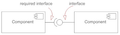
II . The relation Computer with Object or output or load using Interface

Input / Output Interface System between Digital Systems and Analog Systems
The use of computers today is no longer limited to processing and manipulating data but has been used to control various devices such as telephone pulse counters, turning on / off lights automatically, and so on. With the use of computers as mentioned above, it is as if the computer plays a role as a human that can be programmed to do what the programmer wants.
Between digital systems (as controllers) and analog systems (as controlled equipment) there must be a bridge that connects the two systems. This bridge is then called the IO interface system.
So for digital control systems this always consists of 3 parts, namely: digital systems, IO interface systems and analog systems. Digital system is a system that becomes the brain of the whole system. This digital system reads the conditions of an analog system through an IO interface system and controls an analog system through an IO interface system.
This digital control system replaces the manual control system that uses mechanical switches and is manually set. In addition, with this digital control system, the condition of the control system that is controlled can also be monitored. Analog systems are part of analog equipment whose activities are controlled by digital systems through IO interface systems. Analog systems can be 220 volt bolts, AC motors, or even industrial equipment that uses large currents.
Here, it can be seen that the IO interface system is very important, namely to interfere with digital systems that only recognize the condition 'H', which is equivalent to 4.5 volts to 5 volts and the condition 'L' which is equivalent to a voltage below 1.2 volts with an analog system with a voltage of 220 VAC with current consumption of at least 1A and above.
From the conditions above, it is necessary for the digital part and the analog section to pass through an interface system that is electronically isolated between its parts. IO interface techniques here are several techniques and each of these techniques has special features in the application.
Application Example
By using a PC it is expected to be able to control 10 pieces of lights that turn on / off at certain hours. Through a PPI card (using the PPI 8255 chip) 24 loads can be controlled. The PPI output is a TTL level while the lights used are ordinary TL lights. To interconnect between PPI (digital systems) with lights (analog systems) 5volt relays are used.
An example of this application is one example of the use of a relay as an interafce between digital systems and analog systems.
I / O Interface System
The best I / O interface systems are interface systems where digital systems and analog systems are isolated, separate. Usually used a relay or optocoupler. The use of relays is easier but more often causes problems because relays can generate noise in digital systems when the relay changes in state. In addition, the use of relays requires greater power compared to optoisolator use.
A good interface system generally uses optoisolator or better known as an optocoupler like 4N31 or 4N35. By using a current optocoupler that is used for at least 10 mA-15 mA.
The use of an optocoupler such as 4N35 is preferred over using a relay directly.
Optoisolator
Optoisolator is a component used as an I / O control component for equipment operating with DC or AC voltage. An optocoupler consists of a GaAs LED and a silicon NPN phottransistor
The most important factor in the I / O interface, especially for loads that use AC voltage, isolation is the most important thing and must be considered in the design. Digital systems use + 5volt voltage levels while loads use 220VAC voltage. This voltage difference is enough to cause the digital control system, for example, to be damaged if the port on this computer receives an impact voltage from 220VAC load.
optoisolator gets a voltage of 115VAC, but the current is only 8mA and a current of this magnitude is enough to make the phototransistor active and the logic received by the inverter becomes 'low'. With this circuit we get a periodic pulse with the same frequency as the 50 / 60Hz voltage frequency but in the form of a pulse. With the pulse at Pulse Out, it can be ascertained that there is still a voltage on the network, whereas if there are no pulses, the network voltage is 0 VAC.
The disadvantage or disadvantage of the optocoupler is the switching speed. This is due to the effect of the area that is sensitive to light and the effect of capacitance on the 'junction'. If you need a switching speed that is high enough, the optoisolator must be configured so that it is used as the photodiode .
Another way to isolate between a high voltage circuit and a low voltage circuit is to use a relay. The weakness of the relay is the price of a relay with a large current capacity that is quite expensive, the size of the dimensions of the relay is large so that the PCB used is also bigger, causing noise signals, and the response is slow. Whereas by using an optocoupler, the size is small so that the size of the PCB becomes smaller and in the end the equipment becomes smaller too, the response speed is faster.
Use of Solid State Relay (SSR)
In the discussion above, relays can still be used but for now it is preferred to use solid state relays because there are two considerations, namely the effect of noise generated is not too large and the price of solid state relays is relatively cheaper than a relay of the same quality.
There is one more factor that needs to be considered to control the load using AC voltage. That is on the problem of activation time. Because the voltage for the AC always changes, the activation of the solid state relay must be carried out when the AC voltage is approaching zero volts. The aim is to extend the life of the solid state itself because if the SSR activates when the AC voltage is at 220VAC for example, there will be a 'surge current' which can cause very large currents and eventually cause the solid state relay to break.
To overcome this, the use of a solid state relay must also be accompanied by a series of zero crossing detectors. This zero crossing detector circuit will detect when this VAC voltage is at zero volts. With the notification of this condition, when the solid state relay activation can be determined and the solid state relay can work properly.
III . Automatic System with Relation Computer __ Computer ___Object __ Controlling
AUTO SYSTEM
Automated systems (US Automation System) are PC computer-based workstation devices and microcomputer control modules with distributed processing capabilities, and allow the addition of input / output functions and the development of control / processing functions.
The automatic system includes the following components:
1. Operation Workstation - Consists of computers Workstation Operators for operation and Engineering Workstations for maintenance, along with printers. This workstation must work according to standard software for the network controller system and the digital control system of the manufacturer.
2. Ethernet-based Network Controllers - These network controllers connect Workstations directly through Ethernet cables for communication with digital controllers and their input / output modules, also the entrance to communication with other equipment.
3. Digital controller (Digital Control Unit - Controller) - consists of several units according to the system it controls. Each unit operates on its own so-called SDCU (Stand-alone Digital Control Units), contains input / output (I / O) and programs (software) to control equipment under its control.
4. Modem - useful for remote checking of automated systems. Modem with a minimum capacity of 28.8 Kbaud and capable of accessing all network (network) controllers
Automatic System Architecture
Automatic control system consists of:
a. Network Control Units (NCUs) - Network controllers
b. Standalone Digital Control Units (SDCUs) - Digital controllers
c. Unit Modules Input / Output (IOU Modules),
d. Operation Workstations (OWs),
e. File Server to help configure systems with more than one workstation.
The automated system implements controls, alarm detection, management reporting and information for all facilities, and Wide Area Network (WAN) from a single ODBC-complient database.
Network Level 1, is the main backbone of an automated system, in the form of an Ethernet LAN / WAN. Network Control Units, Workstations Operators, and File Servers are connected directly to this network without the gateway (entrance) tool.
Network Level 2 of the system consists of one or more field-bus (profibus) regulated by the Network Control Unit. Level 2 buses consist of one or both of the following types:
1. RS485, token passing bus that serves up to 127 Standalone Digital Control Units (SDCUs)
2. RS485 field-bus serving up to 32 plug-in / out module I / O equipment
These I / O modules are paired directly on the NCU or separated from NCU via wiring.
Automated systems can be segmented through software into multiple LANs that are spread on one WAN using a single file server, allowing workstations to set up one LAN (buliding), and the entire system with all connected equipment to be updated and to use the latest database . If there is only one workstation system, it will contain the entire database, does not require a separate file server.
All NCU, Workstation and File Servers can be connected directly to Ethernet TCP / IP LAN / WAN without the need for a gateway. Furthermore, NCU, Workstation and File Servers can use standard Ethernet infrastructure components that are on the market, such as routers, switches and hubs.
In addition to the LAN / WAN architecture above, software from the same workstation must be able to manage the remote system via dial-up phone channels as a standard component of the software.
Remote system architecture consists of two levels of provision of controls, alarm detection, reporting management and information for remote facilities.
Level one consists of:
• Remote Site Control Unit (RSCU), communication to remote locations (remotely)
• Operation Workstation, via a modem and a standard dial-up phone line.
Level two consists of one or more field-buses that are controlled by RSCU
System development (System expansion)
Automated systems can be scaled and developed at all levels using the same software interface, and the same level 1 and 2 controllers.
Automatic system development includes the Security and Access Control functions without adding workstations, front level controller 1 software is needed. SCDU digital controllers or I / O modules can be added to existing level 1 controller field-buses, to perform security applications and card access.
This system must use the same application language for all levels: Workstation, Network Control Unit, Remote Site Control Unit and Standalone Digital Control Unit. Furthermore, this single program language must be used in all environmental control applications, card access control, interference detection and security, and digital data communication interfaces to other micro-processor-based equipment.
NETWORK CONTROLLER (NCU - Network Control Unit)

The network controller must be microprocessor, multi-tasking, multi-user, and implement a real time operating system. Each NCU control panel consists of modular devices including power supply, CPU board, and input / output modules.
NCU for local telephone dial-up telephone must be the same as NCU Ethernet, but without an Ethernet network interface card (NIC) plug-in, for example, NCU which includes NICs, must be able to exchange on local LAN / WAN or dial-up.
Use of Webserver (Webserver Functionality)
All NCUs on Ethernet TCP / IP LAN / WAN must be set-up as a Web Server. NCU harsu is able to store HTML code and as a web browser page, so it can serve every computer equipment that uses an TCP / IP Ethernet connection and is able to run standard Internet browsers (Microsoft Internet Explorer, Netscape Navigator, etc.) to access real-time data from the whole system automatically through each NCU.
Text-based graphics and web pages must be created using standard HTML code. The interface allows users (users) to select each standard text and editoe HTML-based graph to create pages. Also allows operators to create official graphic pages and formats.
The WEB server interface must be able to use password security, including validating requests for PC computer IP addresses; also allows shared use of data or information between all controllers, or processes or network interfaces (BACnet, LonTalk and TCP / IP) that BMS knows without care where they are connected to the network and / or where needed.
The network controller must immediately function as a WEB server, directly create HTML code to users who need it (WEB browser), so that no software and hardware is needed on the PC-based WEB server. To simplify graphical image space (graphic image), graphical HTML images, if necessary, can be stored on any shared (shared) network equipment. This automatic WEB server system must be able to accept every necessary graph by using the standard pathing syntax according to the HTML code on it. Outside hardware and software is not acceptable.
Hardware specifications:
- Memory RAM - capacity of 4MB to 8MB, including one floating-point math co-processor
- Communication Port - each NCU provides communication to workstations and field-buses; there are at least 3 other port connections for telephone modems, portable service devices, series printers and to other types of controllers; on LAN / WAN systems, NCU is available with a network interface card for Ethernet TCP / IP plug-ins with a capacity of 10Mbps.
- Input / Output (I / O) - each NCU must serve additional input and output of the following types:
• Digital input to turn on status / alarm
• Input counter to add pulse pulses from the meter.
• Thermistor input for temperature measurement
• Analog inputs for measuring pressure, flow rate and surface height.
• Digital output to switch equipment controls on and off.
• Analog output to adjust valve opening, damper and main equipment control capacity.
- Modules that can be developed - this system implements a modular I / O model for easy development. Input and output capacities are available through various types of loose stitch modules. You can also combine I / O modules as needed by individual control applications. At least 10% of available input / output capacity inventory.
- Hardware Override Switches - digital output output units are equipped with a three-position manual switch to select the output state ON, OFF or AUTO. This switch is installed in the unit and is feedback to the controller so that the switch position can be generated via software. Also, each analog output is equipped with a potentiometer (override potentiometer) for manual settings of the analog output signal in full range, when the manual switch 3 position is positioned to ON.
- Local status indication lights - provides the least LED indication for CPU status, Ethernet LAN status, and field-bus status. At each output, it provides an LED indication for the On or Off output state. At each output module, it provides an LED that indicates whether there is output on the module that is being manually (manually overridden).
- Real Time Clock (RTC) - every NCU has a back-up battery and a real time clock that is accurate up to 10 seconds per day. RTC prepares: time, day, month, and year. In normal operation, the system clock is based on the frequency of the AC power source.
- Power supply - NCU power supply is 120-220VAC automatic type, 60/50 Hz with +/- 20% tolerance. If the input voltage is less than the permitted power, it will be turned off. The controller is equipped with overvoltage protection, and does not need an additional converter.
- Automatic restart after power supply disruption - when power recovery after power supply disruption, NCU automatically without human intervention will update all monitored functions, continue previous ongoing operations, synchronize time and status, and implement start strategies - special ups needed.
- Back-up batteries - each NCU with a standard 120-220VAC power supply, equipped with a programmable DC current backup supply system, which can last for 72 hours to keep all memory floating (volatile), or 2 hours as a full UPS. This DC current backup system must be configured after functioning as a full UPS, the unit will turn off the full UPS function and only function to maintain memory.
Software specifications
NCU contains flash ROM as the operating system that occupies it. Application software as RAM that occupies it. Application software is only limited by the amount of RAM memory. There will be no restrictions placed on the type of application program in this system. Each NCU is able to process in parallel, and implement control programs simultaneously. Each program can affect the operation of each other program. Each program has full access to all I / O processor facilities. The execution of this control function will not be disrupted by normal communication by users such as interrogation, entering the program, printing out programs for storage, etc.
User programming language
Application software is a program that can be programmed by the user (user) which includes all strategies, sequence operations (sequence), algorithm control, parameters, and set-points. The program is based on English and can be programmed by users. Discuss them to be structured to facilitate configuration of control programs, alarms, reports, communication, mathematical calculations, passwords and history. The language must prove its own truth (self-documenting). Users must be able to place information anywhere in the program. The sequence of programs must be compiled by users in logical grouping.
Control software
NCU must be able to do the pre-tested algorithms of controls:
• Proportional, Integral plus Derivative Control (PID)
• Self Tuning PID
• Two Position Control
• Digital Filter
• Ratio Calculator
• Equipment Cycling Protection
1. Mathematical Function:
Each controller must be able to carry out basic mathematical functions (+, -, *, /), squares, square roots, exponents, logarithms, Boolean logic, or combinations thereof. Controllers must also be able to carry out complex logic functions including operations such as>, <, =, AND, OR, XOR, etc. These things must be used on the same equation with the mathematical operator and five parentheses.
2. Application of energy management
NCU must be able to carry out every or all of the following routine energy management:
• Time of Day Scheduling
• Calendar Based Scheduling
• Holiday Scheduling
• Temporary Schedule Overrides
• Optimal Start
• Optimal Stop
• Night Setback Control
• Enthalpy Switchover (Economizer)
• Peak Demand Limiting
• Temperature Compensated Duty Cycling
• CFM Tracking
• Heating / Cooling Interlock
• Hot / Cold Deck Reset
• Free Cooling
• Hot Water Reset
• Water Reset Condenser
3. Historical logging
Each controller must be able to log each system variable over a period of time from 1 second to 1440 minutes. Each system variable (input, output, mathematical calculation, flag / image etc.) can be recorded in history. Maximum 32767 prices can be saved in each log. Each log can record the instantaneous, average, minimum or maximum price of each parameter. Logs can be automatic or manual; data that has been logged must be able to be downloaded to Operation Workstation for long-term archiving based on user-specified time frames, or manual commands.
4. Alarm Management
For each system point, an alarm can be made with an upper / lower limit statement or condition. All alarms will be tested every time the NCU scan and can be shown in the alarm system or reporting.
Up to 8 alarms can be arranged at any point in the controller.
Warning messages and reports can be sent to the local terminal, to the front end of the workstation, or through a modem to remote computing devices.
The alarm appears based on its priority. At least 255 levels of priority must be provided.
If communication with the workstation is interrupted temporarily, the alarms will be temporarily (buffered) within NCU. If communication is normal, the alarm will be sent to the workstation if the alarm is still in an alarm condition.
5. Reporting (reporting)
NCU must be able to bring up user-specified reports to the printer or terminal that is connected to the place. Reports must contain a combination of text and system variable quantities
The NCU will be able to generate user-defined reports for a locally connected printer or terminal. Combination of text and system variables. The report form (template) must be user-created on a word processing environment. Reports can be displayed based on logic conditions or through user-generated commands.
DIGITAL CONTROL UNITS (SDCU) - digital controller
Digital control unit must control each system in each power generation unit, namely:
- Gas turbine controller (gas turbine controller)
- Steam turbine controller
- boiler controller (boiler controller)
Each digital control unit has its own program and will continue to operate even if there is interference or loss of communication with its NCU.
Digital controllers as controllers of power generation units must fulfill the following:
- Serve (support) all points of input and output needs according to the sequence (sequence) and operate in stand-alone fashion
- Can be programmed in full by the user (fully user programmable), and the applied software can be modified.
- Operation through a monitor or LCD display is available to find out the price of the parameter and allows the operator to change the set-point price and system parameters.
- There are manual switches (manual override switches) for all digital and analog outputs; the position of the switch is monitored in the software and appears on the operator's display and the alarm system
RAM and EPROM memory
The control program will still be stored in RAM backed up with batteries and in EPROM. Each user's RAM memory for the controller is at least 32kb and 128KB EPROM.
Communication port (port)

SCDU has a communication port with the field-bus. A port connection is also provided for connection with portable service tools for commissioning and changing parameters with or without NCU online. It may also be from the service connection on each SCDU to view, enable / disable, and modify the value of the size of a parameter point or program in each controller on the local field-bus.
Input / Output
Each SCDU must provide additional input and output for the following types:
• Digital Inputs for status / alarm contacts
• Counter Inputs for summing pulses from meters.
• Thermistor Inputs for measuring temperatures in space, ducts and thermowells.
• Analog for pressure, humidity, flow and position measurements.
• Digital Outputs for on / off equipment control.
• Analog Outputs for valve and damper position control, and capacity control of primary equipment.
Expandable input and output capacity can be developed using plug-in / out modules. Two input or output modules can be added to the main SCDU without increasing the power supply capacity.
Each SDCU can exchange information peer-to-peer with other SCDUs during each field-bus scan; can also store and reference large global variables (on LAN) with or without each workstation on-line. The control programs for each SDCU can be viewed and / or enabled / disabled from locally with a portable service tool or workstation connected to an NCU.
The indication light on the SDCU is minimal, an indication of the CPU status LED and field-bus status.
Real Time Clock (RTC)
An SCDU must have a real time clock on the hardware and software. Accuracy in 10 seconds per day. RTC includes the following information: time, day, month and year. Each SCDU receives one signal every hour, through a network from NCU that equates the RTC throughout the SCDU.
Automatic restart after power supply interruption
When power recovery after power supply interruption, NCU automatically without human intervention will update all monitored functions, continue previous ongoing operations, synchronize time and status, and implement special start-up strategies needed.
Back-up battery
Each SCDU is equipped with a back-up battery that can last up to 3 years to keep all memory easily erased (volatile).
Alarm Management
For each system point, an alarm can be made with an upper / lower limit statement or condition. All alarms will be tested every time the SDCU scan and can be shown in the alarm system or reporting.
Up to 8 alarms can be arranged at any point in the controller allowing an increase in urgency based on which alarm is triggered.
Warning and reporting messages can be sent to a local terminal or modem connected to NCU or to Operation Workstation.
The alarm appears based on its priority. At least 255 levels of priority must be provided.
If communication with NCU is interrupted temporarily, alarms will be temporarily (buffered) in SDCU. If communication is normal, the alarm will be sent to NCU if the alarm is still in an alarm condition.
The control program will still be stored in RAM backed up with batteries and in EPROM. Each user's RAM memory for the controller is at least 32kb and 128KB EPROM.
Communication port (port)
SCDU has a communication port with the field-bus. A port connection is also provided for connection with portable service tools for commissioning and changing parameters with or without NCU online. It may also be from the service connection on each SCDU to view, enable / disable, and modify the value of the size of a parameter point or program in each controller on the local field-bus.
Input / Output
Each SCDU must provide additional input and output for the following types:
• Digital Inputs for status / alarm contacts
• Counter Inputs for summing pulses from meters.
• Thermistor Inputs for measuring temperatures in space, ducts and thermowells.
• Analog for pressure, humidity, flow and position measurements.
• Digital Outputs for on / off equipment control.
• Analog Outputs for valve and damper position control, and capacity control of primary equipment.
Expandable input and output capacity can be developed using plug-in / out modules. Two input or output modules can be added to the main SCDU without increasing the power supply capacity.
Each SDCU can exchange information peer-to-peer with other SCDUs during each field-bus scan; can also store and reference large global variables (on LAN) with or without each workstation on-line. The control programs for each SDCU can be viewed and / or enabled / disabled from locally with a portable service tool or workstation connected to an NCU.
The indication light on the SDCU is minimal, an indication of the CPU status LED and field-bus status.
Real Time Clock (RTC)
An SCDU must have a real time clock on the hardware and software. Accuracy in 10 seconds per day. RTC includes the following information: time, day, month and year. Each SCDU receives one signal every hour, through a network from NCU that equates the RTC throughout the SCDU.
Automatic restart after power supply interruption
When power recovery after power supply interruption, NCU automatically without human intervention will update all monitored functions, continue previous ongoing operations, synchronize time and status, and implement special start-up strategies needed.
Back-up battery
Each SCDU is equipped with a back-up battery that can last up to 3 years to keep all memory easily erased (volatile).
Alarm Management
For each system point, an alarm can be made with an upper / lower limit statement or condition. All alarms will be tested every time the SDCU scan and can be shown in the alarm system or reporting.
Up to 8 alarms can be arranged at any point in the controller allowing an increase in urgency based on which alarm is triggered.
Warning and reporting messages can be sent to a local terminal or modem connected to NCU or to Operation Workstation.
The alarm appears based on its priority. At least 255 levels of priority must be provided.
If communication with NCU is interrupted temporarily, alarms will be temporarily (buffered) in SDCU. If communication is normal, the alarm will be sent to NCU if the alarm is still in an alarm condition.
Gas turbine controller (gas turbine controller)
The gas turbine controller must be able to carry out all the needs and control of the operation of the gas turbine according to the specifications specified in the execution part with its control program.
Control of the gas turbine consists of:
• Ready to start (stand by)
• Start-up / shutdown of the program
• In operation, which consists of:
o Temperature Control
o Speed Control
o Load Control
- Ready to start = is a series of logic (logic sequence) to meet the requirements so that the gas turbine unit can be started (start).
- Program start-up / shutdown = is a step program (program control) to meet the criteria and limitations during the start-up (start-up) or during the shutdown of the gas turbine unit.
- Temperature control = is a continuous control as long as the gas turbine unit operates to limit the exhaust gas temperature of the gas turbine so that it does not exceed the predetermined temperature limit.
- Speed control = is continuous control (continuous control) as long as the gas turbine unit operates to keep the gas turbine shaft rotating to remain constant according to a predetermined cycle.
- Load control = is continuous control (continuous control) as long as the gas turbine unit operates to control the unit load according to the desired target, while still maintaining the rotation of the gas turbine shaft to remain constant according to a predetermined cycle.
Steam turbine controller (steam turbine controller)
The steam turbine controller must be able to carry out all the needs and control of the operation of the steam turbine according to the specifications specified in the execution part with its control program.
Steam turbine control consists of:
• Ready to start (stand by)
• Start-up / shutdown of the program
• In operation, which consists of:
o Speed Control
o Load Control
- Ready to start = is a series of logic (logic sequence) to meet the requirements so that the steam turbine unit can be started (start).
- Start-up / shutdown of the program = is a step program (program control) to meet the criteria and limitations during the start (start-up) or during the shutdown (shutdown) of the steam turbine unit.
- Speed control = is continuous control as long as the steam turbine unit operates to maintain the rotation of the steam turbine shaft to remain constant according to a predetermined cycle.
- Load control = is continuous control (continuous control) as long as the steam turbine unit operates to control the unit load according to the desired target, while still maintaining the steam turbine shaft rotation to remain constant according to a predetermined rotation.
Boiler controller
The boiler controller must be able to carry out all the needs and control of the operation of the steam turbine according to the specifications specified in the execution part with its control program.
The boiler control consists of:
• Ready to start (stand by)
• Start-up / shutdown of the program
• In operation, which consists of:
o Boiler tank level control (drum level control)
o Steam pressure control
o Control the flow of feed water control
o Shortcut steam control (steam by-pass control)
o Fuel control (access air control)
- Ready to start = is a series of logic (logic sequence) to fulfill the requirements so that the boiler unit can be started (start).
- Start-up / shutdown of the program = is a step program (program control) to meet the criteria and limitations during the start (start-up) or during the shutdown (shutdown) of the steam turbine unit.
- Drum level control = is continuous control as long as the boiler unit operates to keep the water level in the boiler tank constant at the specified level.
- Steam pressure control = is continuous control (continuous control) as long as the boiler unit operates to control steam pressure according to the desired target.
- Feed water control = is continuous control (continuous control) as long as the boiler unit operates to control the flow of fill water in accordance with the desired target.
- Steam by-pass control = is continuous control as long as the boiler unit operates to restore the steam flow from the boiler to the condenser, if the amount of steam produced by the boiler far exceeds the steam requirement for the steam turbine.
- Access air control = is continuous control as long as the boiler unit operates to control the fuel air flow from the FDF fan to the combustion chamber so that it is proportional to its fuel requirements.
Monitor controller (display controller)
The monitor controller is stand alone, as an operator intermediary with the machine through the monitor screen. The software can be programmed by the user to create a graphic image to simulate according to the current (real time) prices coming from NCU; change appearance, operate equipment and change the set-point reference.
OPERATOR and ENGINEERING WORKSTATION
Software on the workstation must be able to be formed into a single system (single workstation) with a local data base, or a dual system (multi workstation) where the database is placed on the central file server. Client software on multiple multi-workstation systems must access the database file server program through an Ethernet TCP / IP series that works at 10MBPS or 100MBPS.
All PC-based workstations with Windows operating systems. Application software must be able to communicate throughout NCU and SDCU, characterized by high-resolution color graphics, alarm alerts, reporting, collection of data that can be compiled by users and data presentation functions.
For multi-workstation systems, at least up to 256 workstations can be connected to an Ethernet network with the central file server. In this client / server configuration array, any changes or additions made from one workstation will automatically appear on all workstations without the need to copy the files manually. Multi-workstation systems without a central database are not acceptable. A multi-workstation system with a distributed / bound and central database (master) file server that is acceptable.
Complete Workstation (single or multi-workstation configuration).
750 MHz Pentium III (or greater) processor with 256MB of RAM
Microsoft NT Workstation operating system
Two serial ports
10MBPS or 10 / 100MBPS Ethernet NIC
GB 20 GB hard disk
3½ "diskette drive
CD-ROM drive
SVGA compatible, 19 "monitor.
Mouse
Full function keyboard
Audio sound card and speakers
License agreement for all applicable software.
Completeness of computer File Server
750 MHz Pentium III (or greater) processor with 512MB of RAM
Microsoft NT Server operating system
10MBPS or 10 / 100MBPS Ethernet NIC
30GB hard disk
3½ "diskette drive
CD-ROM drive
SVGA compatible, 14 "monitor.
Mouse
Full function keyboard
License agreement for all applicable software.
Modem that is compatible with Workstation (33.6 Kbaud)
Printer
Printer for alarms and printers for separate graphics or reports. Alarm printers are usually Epson dot matrix or similarities, and printers for reporting are usually laser-jet types.
Software for workstations
Software architecture planning must be object-oriented, 32-bit applications suitable for Microsoft OLE, COM, DCOM and ODBC technologies. This technology makes it easy to use all operating system capabilities to be shared between applications (and for users of these applications), a wealth of data is available from BAS.
The workstation function includes monitoring and programming of all DDC controllers. Monitoring consists of tracking, reporting, graphical display, long-term data storage, automatic data collection, and control actions by operators such as schedule and setpoint settings.
Programming controllers must be able to be done off-line or on-line from any engineering workstation. All information must be available in graphical or text view. Graphical display features animation effects to enrich data presentation, remind operators of problems, and to facilitate the location of information throughout the DDC system. All operator functions can be selected via the mouse.
Database system
The database file server engine must be Microsoft SQL Server, or another ODBC (Open Database Connectivity) client, a relational database program. This database engine ODBC client allows the owner to use the database of his choice and because the open architecture allows owners to write official applications and / or reports that directly communicate with the database avoiding the transfer of ordinary data to update the other application. The system database contains all configuration points and programs in each controller that has been placed in the network network. Also, the database contains files of all workstations in the form of color graphics (color graphics), alarm reports, text reports, historical data logs, schedules, and polling records.
User Interface
Workstation BAS (Building Automation System) software allows custom browser-style interfaces to be connected to the logged user to the workstation software. intermediate will support the creation of "hot-spots" so that users can connect to view and edit each object in the system or run an editor or configuration tool for each object in the software. Furthermore, intermediaries
Automatic monitoring (automatic monitoring)
Software must be able to automatically collect data and reports from any controller through cable communication (hardwire) or modem connections. The frequency of data collection must be fully configurable by the user.
Alarm management
Software must be able to receive an alarm directly from the controller, or make an alarm based on evaluation of the data on the controller and compare the boundaries or conditional equations configured through the software. Each alarm (no matter the origin) will be integrated into the overall alarm management system and will be displayed on all standard alarm reports, ready for the operator to respond, and there are options to be displayed graphically or report.
Alarm management includes:
• At least 255 alarm notification levels. Each level will create a unique set of parameters for alarm control displays, acknowledgments, keyboard annexation, alarm printouts and save recordings.
• Automatic logging in the alarm news database, name point value points, connected controller, timestamp, user name and time to respond and soft acknowledgment time.
• Automatic print alarm information or alarm reports on alarm printers or report printers.
• Sounds a beep or audio file at the start of an alarm or returns to normal.
• Send an e-mail or alphanumeric page to each one that is listed in the workstation's e-mail address at the start of an alarm or a recurring alarm because the operator has not responded to the alarm within the user-specified time period. The ability to use e-mails and alphanumeric alarms must be a feature of a software standard integrated with the operating system application mail OS (OS MAPI). No need for special software intermediaries.
• Individual alarms must also be displayed on workstations whose time and date are user-defined; for example, alarms "very high lubricating temperatures" are displayed in the Management Section workstation for hours and working days and to Central Alarming workstations at any time.
• Includes an active alarm monitor that can be assigned to each user to show or hide alarm attributes.
• The type and color of the font (font), and the back color of each alarm news level as shown in the active alarm monitor can be determined to facilitate identification of certain types of alarms or alarm conditions.
• Active alarm monitors can be configured so that the operator must write down the alarm whole or take from the list of user actions for a particular alarm; this guarantees accountability (audit trail) to respond to critical alarms.
Reporting (report generation)
Software contains report generation with word processing devices to create reports that can be setup to run automatically or if needed. Each workstation can collect reports with existing spreadsheet word processing programs. When a report is displayed, it automatically spreads to connected report editors such as Word, WordPerfect, NotePad, or Lotus 123
• Reports can be as long as anything and contain any attribute points from any controller that is connected to the network network.
• Report makers have access to user programming languages to perform mathematical calculations within the report framework, control report display output, or make it easier for users to provide additional information needed for reporting.
• Allows performing other execution programs whenever a report starts.
• Report-making activities can be connected to an alarm management system, so that each configured report can be displayed to respond to an alarm condition.
• Standard reports include:
Points in each controller.
Points in alarm
Disabled points
Overridden points
Activity report operator
Alarm history log.
Program listing by controller with status.
Network status of each controller
Spreadsheet type report (spreadsheet-style report)
The software also provides simple reporting of row and column types on each object class in the system, which can be configured by the user and retrieves fresh data from the controller or from the database. Users can setup each report displayed in the form of letters and colored backgrounds, can also be configured to filter data, select data and highlight data according to user-specified criteria.
HTML (HTML reporting) reporting
A spreadsheet type report can be run in an HTML template file, to create an HTML result file in the HTML template directory. This directory can be used in conjunction with other computer users to access directories to point their web browsers to files and view reports.
Settings (scheduling)
It is possible to configure and download from workstation settings
COMMISSIONING AND SYSTEM STARTUP
A. Point to Point Checkout.
Each
I/O device (both field mounted as well as those located in FIPs) shall be
inspected and verified for proper installation and functionality. A checkout sheet itemizing each device shall
be filled out, dated and approved by the Project Manager for submission to the
owner or owner’s representative.
B. Controller and Workstation Checkout.
A
field checkout of all controllers and front end equipment (computers, printers,
modems, etc.) shall be conducted to verify proper operation of both hardware
and software. A checkout sheet itemizing
each device and a description of the associated tests shall be prepared and
submitted to the owner or owner’s representative by the completion of the
project.
C. System Acceptance Testing
1. All
application software will be verified and compared against the sequences of
operation. Control loops will be
exercised by inducing a setpoint shift of at least 10% and observing whether
the system successfully returns the process variable to setpoint. Record all test results and attach to the
Test Results Sheet.
2. Test
each alarm in the system and validate that the system generates the appropriate
alarm message, that the message appears at all prescribed destinations
(workstations or printers), and that any other related actions occur as defined
(i.e. graphic panels are invoked, reports are generated, etc.). Submit a Test Results Sheet to the owner.
3. Perform
an operational test of each unique graphic display and report to verify that
the item exists, that the appearance and content are correct, and that any
special features work as intended.
Submit a Test Results Sheet to the owner.
4. Perform
an operational test of each third party interface that has been included as
part of the automation system. Verify
that all points are properly polled, that alarms have been configured, and that
any associated graphics and reports have been completed. If the interface involves a file transfer
over Ethernet, test any logic that controls the transmission of the file, and
verify the content of the specified information.
Tidak ada komentar:
Posting Komentar