Pythagorean theorem reads in a right-angled triangle the hypotenuse squared same applies to the number of squares of the other sides. In general, if the triangle ABC is right-angled in C then the Pythagorean theorem can be stated AB ^ 2 = AC + BC ^ 2 ^ 2.
The Pythagorean Theorem is a very famous theorem. This theorem will be used in calculating the broad flat wake. Besides being used in the calculation of the flat wake, calculations in 3 dimensions or the other will also often use the Pythagorean theorem. Many books write this theorem as c ^ 2 = a ^ 2 + b ^ 2. Where c is the hypotenuse.
Proof of this theorem is very diverse. Very many ways to prove Pythagoras's theorem. Here will be given some proof of the Pythagorean theorem. From the very basic evidence until proof is quite complicated. Most evidence of the Pythagorean theorem is the development of core evidence (evidence base).
I. The first evidence :

Supplied four right-angled triangles. Look at the picture above. 4 triangles above are similar triangles. Have the sides a, b and c. and side c is the hypotenuse of the triangle. The third triangle side are the result of the rotation of 90, 180 and 270 degrees of the first triangle.
The area of each triangle is \ frac {ab} {2}. So spacious 4 triangles are 2ab.
The triangles be set so that membentung square with side c as shown below.

Note the image of the arrangement 4 the triangle. The images form a square with sides c. and in it there is a small square. The long side of the small square is (b-a).
Directly we can determine the extent of the huge square, ie c ^ 2. And indirectly, a large square area with side c is equal to the area of 4 triangles plus a small square area having a side (b-a). Thus obtained,
c ^ 2 = 2ab + (b-a) ^ 2
c ^ 2 = 2ab + b ^ a ^ 2 + 2-2ab
c ^ 2 = b ^ 2 + a ^ 2
II. the second proof

Note the picture. The picture is a picture of 2 square. Large square is a square that has a side length, and a small square has a side length that is b.
Large square area that certainly is a ^ 2. And a small square area is b ^ 2. So spacious wake above is b ^ 2 + a ^ 2

Both the square we combine. And we created a line so that as in the picture. C side becomes the hypotenuse of the triangle. then we cut into triangles. and we move it to the top and right side as shown below.

Square area with a side c of the course is c ^ 2. Because the two square at the outset is equal to one large square with sides c above, then certainly an area of 2 square equal to the area's first large square with the c side.
thus, c ^ 2 = b ^ 2 + a ^ 2
III. The third proof

The picture is a picture of a trapezoid made up of three triangles. The spacious trapezoid is \ frac {1} {2} (a + b) (a + b). searched using the trapezoidal area formula. That is half multiplied by the number of times the high side of the parallel trapezoid. Seek broad flat wake above can also use an extensive number of triangles (see picture). that is
\ Frac {1} {2} ab + \ frac {1} {2} ab + \ frac {1} {2} c ^ 2.
Size counts is fixed. Namely the trapezium shape. so it should be both widely sought by the different steps that should be the same. Retrieved,
\ Frac {1} {2} (a + b) (a + b) = \ frac {1} {2} ab + \ frac {1} {2} ab + \ frac {1} {2} c ^ 2
\ Frac {1} {2} (a ^ 2 + 2ab + b ^ 2) = ab + \ frac {1} {2} c ^ 2
\ Frac {1} {2} a ^ 2 + ab + \ frac {1} {2} b ^ 2 = ab + \ frac {1} {2} c ^ 2
a ^ 2 + b ^ 2 = c ^ 2
MACAM-MACAM BILANGAN TRIPEL PYTHAGORAS
1. (3,4,5)
2. (5,12,13)
3. (7,24,25)
4. (8,15,17)
5. (9,40,41)
6. (11,60,61)
7. (12,35,37)
8. (13,84,85)
9. (15,112,113)
10. (16,63,65)
11. (17,144,145)
12. (19,180,181)
13. (20,21,29)
14. (20,99,101)
15. (21,220,221)
16. (23,264,265)
17. (24,143,145)
18. (25,312,313)
19. (27,364,365)
20. (28,45,53)
21. (28,195,197)
22. (29,420,421)
23. (31,480,481)
24. (32,255,257)
25. (33,56,65)
26. (33,544,545)
27. (35,612,613)
28. (36,77,85)
29. (36,323,325)
30. (37,684,685)
31. (39,80,89)
32. (39,760,761)
33. (40,399,401)
34. (41,840,841)
35. (43,924,925)
36. (44,117,125)
37. (44,483,485)
38. (48,55,73)
39. (48,575,577)
40. (51,140,149)
41. (52,165,173)
42. (52,675,677)
43. (56,783,785)
44. (57,176,185)
45. (60,91,109)
46. (60,221,229)
47. (60,899,901)
48. (65,72,97)
49. (68,285,293)
50. (69,260,269)
51. (75,308,317)
52. (76,357,365)
53. (84,187,205)
54. (84,437,445)
55. (85,132,157)
56. (87,416,425)
57. (88,105,137)
58. (92,525,533)
59. (93,476,485)
60. (95,168,193)
61. (96,247,265)
62. (100,621,629)
63. (104,153,185)
64. (105,208,233)
65. (105,608,617)
66. (108,725,733)
67. (111,680,689)
68. (115,252,277)
69. (116,837,845)
70. (119,120,169)
71. (120,209,241)
72. (120,391,409)
73. (123,836,845)
74. (124,957,965)
75. (129,920,929)
76. (132,475,493)
77. (133,156,205)
78. (135,352,377)
79. (136,273,305)
80. (140,171,221)
81. (145,408,433)
82. (152,345,377)
83. (155,468,493)
84. (156,667,685)
85. (160,231,281)
86. (161,240,289)
87. (165,532,557)
88. (168,425,457)
89. (168,775,793)
90. (175,288,337)
91. (180,299,349)
92. (184,513,545)
93. (185,672,697)
94. (189,340,389)
95. (195,748,773)
96. (200,609,641)
97. (203,396,445)
98. (204,253,325)
99. (205,828,853)
100. (207,224,305)
101. (215,912,937)
102. (216,713,745)
103. (217,456,505)
104. (220,459,509)
105. (225,272,353)
106. (228,325,397)
107. (231,520,569)
108. (232,825,857)
109. (240,551,601)
110. (248,945,977)
111. (252,275,373)
112. (259,660,709)
113. (260,651,701)
114. (261,380,461)
115. (273,736,785)
116. (276,493,565)
117. (279,440,521)
118. (280,351,449)
119. (280,759,809)
120. (287,816,865)
121. (297,304,425)
122. (300,589,661)
123. (301,900,949)
124. (308,435,533)
125. (315,572,653)
126. (319,360,481)
127. (333,644,725)
128. (336,377,505)
129. (336,527,625)
130. (341,420,541)
131. (348,805,877)
132. (364,627,725)
133. (368,465,593)
134. (369,800,881)
135. (372,925,997)
136. (385,552,673)
137. (387,884,965)
138. (396,403,565)
139. (400,561,689)
140. (407,624,745)
141. (420,851,949)
142. (429,460,629)
143. (429,700,821)
144. (432,665,793)
145. (451,780,901)
146. (455,528,697)
147. (464,777,905)
148. (468,595,757)
149. (473,864,985)
150. (481,600,769)
151. (504,703,865)
152. (533,756,925)
153. (540,629,829)
154. (555,572,797)
155. (580,741,941)
156. (615,728,953)
157. (616,663,905)
Pythagoras theory to determine the position of robot
at the moment of making a robot with a special feature heavily dependent according to the needs. One of the sensors used in robots are the rotary encoder
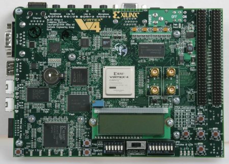
Rotary encoder: a digital sensor used to detect displacement or movement of the robot. Along with the development of robots, FPGA development shows a positive response, so scientists began trying to apply it to the world of robots. One example application is to determine the position of the robot. calculating the position of the robot with FPGA using the rotary encoder.
FPGA (Field Programmable Gate Array) that is programmable major device that is composed of independent logic modules that can be configured through the canals of programmable routing. FPGA is a type IC HDL (Hardware Description Language).
In general, the inner architecture of FPGA IC consists
on three main elements, namely Input / Output Block (IOB), Configurable Logic Block (CLB) and programmable interconnect. Input Output Blocks (IOB), as an interface between the external and internal pins of the device use rlogic .Configure Logic Blocks (CLB), part of which will process all forms of logic circuit and Programmable Interconnect, the part that connects the CLB CLB one with the other


B. Rotary encoder
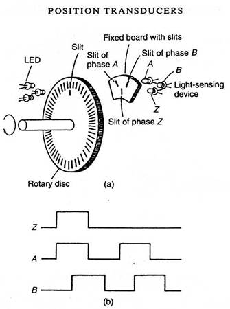
Rotary encoder is an electromechanical device that can monitor the movement and position. Rotary encoder generally uses optical sensors to produce a series of pulses which translates into motion, position, and direction. So that the angular position of a shaft rotating object can be processed into information in the form of digital code by a rotary encoder
Rotary encoder
composed of a thin disk that has holes in the circular disk. LED is placed on one side of the disc so that
the light will be heading to the disc. On the other hand, a photo-transistor is placed so that the photo-transistor can detect light from the LED opposite. When the position of the disk results in light of the LED can achieve photo-transistor through the existing holes, then the photo-transistor will experience saturation and will produce a square wave pulse. The more the pulse train generated in one round determines
The accuracy rotary encoder.

A. System Block Diagram
Block diagram of the system, manually controlled robot (driven), resulting in the movement, rotary encoder, serves to detect the movement. The resulting output rotary encoder
1, rotary encoder
2, and a rotary encoder
3 in the form of pulses that represent the position of the x-axis (x), and the movement of the x-axis angle (θ). De2 by FPGA output data respectively
rotary encoder is processed to be calculated movement of each rotary encoder then proceeds in the form of a position (x, y) is displayed on the LCD
B. Determine the position (x, y) robot
Pythagorean theorem
Round rotary encoder used as a reference as position
the x-axis robot, when the robot walks then it will
generating robot movement angle to the axis x (θ). So with the known position of the x-axis and the angle thetanya, then the position of the y-axis robot can be known by using the Pythagorean theorem. Here is a triangle theorem of Pythagoras.

Rotary encoder adalah divais
elektromekanik yang dapat memonitor gerakan dan posisi. Rotary encoder
umumnya menggunakan sensor optik untuk menghasilkan serial pulsa yang
dapat diartikan menjadi gerakan, posisi, dan arah. Sehingga posisi sudut
suatu poros benda berputar dapat diolah menjadi informasi berupa kode
digital oleh rotary encoder untuk diteruskan oleh rangkaian kendali.
Rotary encoder umumnya digunakan pada pengendalian robot, motor drive,
dsb.
Rotary encoder tersusun dari suatu piringan tipis yang memiliki lubang-lubang pada
bagian lingkaran piringan. LED ditempatkan pada salah satu sisi
piringan sehingga cahaya akan menuju ke piringan. Di sisi yang lain
suatu photo-transistor diletakkan sehingga photo-transistor ini dapat
mendeteksi cahaya dari LED yang berseberangan. Piringan tipis tadi
dikopel dengan poros motor, atau divais berputar lainnya yang ingin kita
ketahui posisinya, sehingga ketika motor berputar piringan juga akan
ikut berputar. Apabila posisi piringan mengakibatkan cahaya dari LED
dapat mencapai photo-transistor melalui lubang-lubang yang ada, maka
photo-transistor akan mengalami saturasi dan akan menghasilkan suatu
pulsa gelombang persegi. Gambar 1 menunjukkan bagan skematik sederhana
dari rotary encoder. Semakin banyak deretan pulsa yang dihasilkan pada
satu putaran menentukan akurasi rotary encoder tersebut, akibatnya
semakin banyak jumlah lubang yang dapat dibuat pada piringan menentukan
akurasi rotary encoder tersebut.
 Gambar 1. Blok penyusun rotary encoder
Rangkaian penghasil pulsa (Gambar 2) yang
digunakan umumnya memiliki output yang berubah dari +5V menjadi 0.5V
ketika cahaya diblok oleh piringan dan ketika diteruskan ke
photo-transistor. Karena divais ini umumnya bekerja dekat dengan motor
DC maka banyak noise yang timbul sehingga biasanya output akan
dimasukkan ke low-pass filter dahulu. Apabila low-pass filter digunakan,
frekuensi cut-off yang dipakai umumnya ditentukan oleh jumlah slot yang
ada pada piringan dan seberapa cepat piringan tersebut berputar,
dinyatakan dengan:
 (1)
(1)
Dimana fc adalah frekuensi cut-off filter, sw adalah kecepatan piringan dan n adalah jumlah slot pada piringan.
 Gambar 2. Rangkaian tipikal penghasil pulsa pada rotary encoder
Terdapat dua jenis rotary encoder yang
digunakan, Absolute rotary encoder dan incremental rotary encoder.
Masing-masing rotary encoder ini akan dipaparkan pada bagian berikutnya.
ABSOLUTE ROTARY ENCODER
Absolute encoder menggunakan piringan dan
sinyal optik yang diatur sedemikian sehingga dapat menghasilkan kode
digital untuk menyatakan sejumlah posisi tertentu dari poros yang
dihubungkan padanya. Piringan yang digunakan untuk absolut encoder
tersusun dari segmen-segmen cincin konsentris yang dimulai dari bagian
tengah piringan ke arah tepi luar piringan yang jumlah segmennya selalu
dua kali jumlah segmen cincin sebelumnya. Cincin pertama di bagian
paling dalam memiliki satu segmen transparan dan satu segmen gelap,
cincin kedua memiliki dua segmen transparan dan dua segmen gelap, dan
seterusnya hingga cincin terluar. Sebagai contoh apabila absolut encoder
memiliki 16 cincin konsentris maka cincin terluarnya akan memiliki
32767 segmen. Gambar 3 menunjukkan pola cincin pada piringan absolut
encoder yang memiliki 16 cincin.

Gambar 3. Contoh susunan pola 16 cincin konsentris pada absolut encoder
Karena setiap cincin pada piringan
absolute encoder memiliki jumlah segmen kelipatan dua dari cincin
sebelumnya, maka susunan ini akan membentuk suatu sistem biner. Untuk
menghasilkan sistem biner pada susunan cincin maka diperlukan pasangan
LED dan photo-transistor sebanyak jumlah cincin yang ada pada absolut
encoder tersebut.
 Gambar 4. Contoh piringan dengan 10 cincin dan 10 LED – photo-transistor untuk membentuk sistem biner 10 bit.
Sistem biner yang untuk menginterpretasi
posisi yang diberikan oleh absolute encoder dapat menggunakan kode gray
atau kode biner biasa, tergantung dari pola cincin yang digunakan. Untuk
lebih jelas, kita lihat contoh absolut encoder yang hanya tersusun dari
4 buah cincin untuk membentuk kode 4 bit. Apabila encoder ini
dihubungkan pada poros, maka photo-transistor akan mengeluarkan sinyal
persegi sesuai dengan susunan cincin yang digunakan. Gambar 5 dan 6
menunjukkan contoh perbedaan diagram keluaran untuk absolute encoder
tipe gray code dan tipe binary code.

Gambar 5. Contoh diagram keluaran absolut encoder 4-bit tipe gray code
Dengan absolute encoder 4-bit ini maka
kita akan mendapatkan 16 informasi posisi yang berbeda yang
masing-masing dinyatakan dengan kode biner atau kode gray tertentu.
Tabel 1 menyatakan posisi dan output biner yang bersesuaian untuk
absolut encoder 4-bit. Dengan membaca output biner yang dihasilkan maka
posisi dari poros yang kita ukur dapat kita ketahui untuk diteruskan ke
rangkaian pengendali. Semakin banyak bit yang kita pakai maka posisi
yang dapat kita peroleh akan semakin banyak.

Gambar 6. Contoh diagram keluaran absolut encoder 4-bit tipe binary code
Tabel 1. Output biner dan posisi yang bersesuaian pada absolute encoder 4-bit

INCREMENTAL ROTARY ENCODER
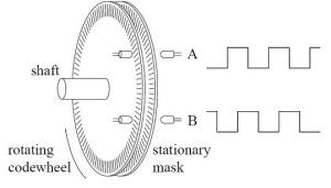
Incremental encoder terdiri dari dua
track atau single track dan dua sensor yang disebut channel A dan B
(Gambar 7). Ketika poros berputar, deretan pulsa akan muncul di
masing-masing channel pada frekuensi yang proporsional dengan kecepatan
putar sedangkan hubungan fasa antara channel A dan B menghasilkan arah
putaran. Dengan menghitung jumlah pulsa yang terjadi terhadap resolusi
piringan maka putaran dapat diukur. Untuk mengetahui arah putaran,
dengan mengetahui channel mana yang leading terhadap channel satunya
dapat kita tentukan arah putaran yang terjadi karena kedua channel
tersebut akan selalu berbeda fasa seperempat putaran (quadrature
signal). Seringkali terdapat output channel ketiga, disebut INDEX, yang
menghasilkan satu pulsa per putaran berguna untuk menghitung jumlah
putaran yang terjadi.
Gambar 7. susunan piringan untuk incremental encoder
Contoh pola diagram keluaran dari suatu
incremental encoder ditunjukkan pada Gambar 8. Resolusi keluaran dari
sinyal quadrature A dan B dapat dibuat beberapa macam, yaitu 1X, 2X dan
4X. Resolusi 1X hanya memberikan pulsa tunggal untuk setiap siklus salah
satu sinya A atau B, sedangkan resolusi 4X memberikan pulsa setiap
transisi pada kedua sinyal A dan B menjadi empat kali resolusi 1X. Arah
putaran dapat ditentukan melalui level salah satu sinyal selama transisi
terhadap sinyal yang kedua. Pada contoh resolusi 1X, A = arah bawah
dengan B = 1 menunjukkan arah putaran searah jarum jam, sebaliknya B =
arah bawah dengan A = 1 menunjukkan arah berlawanan jarum jam.

Gambar 8. Contoh pola keluaran incremental encoder

Gambar 9. output dan arah putaran pada resolusi yang berbeda-beda
Pada incremental encoder, beberapa cara
dapat digunakan untuk menentukan kecepatan yang diamati dari sinyal
pulsa yang dihasilkan. Diantaranya adalah  menggunakan frequencymeter dan periodimeter.
menggunakan frequencymeter dan periodimeter.
Cara yang sederhana untuk menentukan
kecepatan dapat dengan frequencymeter, yakni menghitung jumlah pulsa
dari encoder, n, pada selang waktu yang tetap, T, yang merupakan periode
loop kecepatan (Gambar 10). Apabila α adalah sudut antara pulsa
encoder, maka sudut putaran pada suatu periode adalah:
 (2)
(2)
Sehingga kecepatan putar akan kita dapatkan sebagai:
 (3)
(3)
Kelemahan yang muncul pada cara ini adalah pada setiap periode sudut αf
yang didapat merupakan kelipatan integer dari α. Ini akan dapat
menghasilkan quantification error pada kecepatan yang ingin diukur.

Gambar 10. Sinyal keluaran encoder untuk pengukuran kecepatan dengan frequencymeter
Cara yang lain adalah dengan menggunakan
periodimeter. Dengan cara ini kita akan mengukur kecepatan tidak lagi
dengan menghitung jumlah pulsa encoder tetapi dengan menghitung clock
frekuensi tinggi (HF Clock) untuk sebuah pulsa dari encoder yaitu
mengukur periode pulsa dari encoder (Gambar 11). Apabila αp
adalah sudut dari pulsa encoder, t adalah periode dari HF clock, dan n
adalah jumlah pulsa HF yang terhitung pada counter. Maka waktu untuk
sebuah pulsa encoder, Tp, adalah:

(4)
Sehingga kecepatan yang akan kita ukur dapat kita peroleh dengan:

(5)
Seperti halnya pada frequencymeter, disini juga muncul quantification error karena waktu Tp akan selalu merupakan perkalian integer dengan t.
 Gambar 11. Pengukuran kecepatan dengan menggunakan Periodimeter
Tidak ada komentar:
Posting Komentar