
X . I POWER BLAZER 800W


POWER BLAZER 800W (X8) Power Amplifier Blazer by using transistors 8 pieces (four sets) Sanken on the final side will ensure that the energy produced is very large. You can connect the output to the speakers as large as 18 "or 21" in parallel by 2 pieces (impedance 4 ohms). His bass voice will be jarring despite being in the outdoors. Power is very appropriate for those of you who really want to improve the quality of suarai rental sound system. Blazer in sound system design for use in a field that requires the beat at low frequencies. Power Blazer with this, low tones (bass) which is derived will be deeper and kicking. However, it must be supported by an appropriate speaker and the right speaker Box also in its application. For large-scale use home (Home Audio) Power Amplifier we do not recommend this. However, to generate tones or Mid High Mid, Blazer slightly have the drawback at this point. Nada Mid generated less subtle or less detail. So to your sound system, we recommend using it only for the Power Blazer Low Amplifier only. There satuhal else do you need to consider before merakita Power Amplifier Blazer that was in desperate need supply large currents. For Module X-8 Mono course, you need a minimum of 20 amperes flows suply / 45VAC. To gain greater power, AC voltage should be higher than it is about 55-60 VAC SPECIFICATIONS Power Output: 400W RMS 8 ohms, 600W rms 4 ohms Supply Current: 20A (mono), 30A (stereo) Voltage: 55VAC TR Final : Sanken 2SC3264 / 2SA1295


X . II POWER AMPLIFIER APEX B 500
In the power amplifier circuit schematic APEX following B500 visible part of the Pre-Amp use type IC NE5532. The output of IC NE5532 is given to the driver amplifier transistor. Part of these drivers will have two different outputs of phase from each other by 180 °. Section consists of a driver transistor Q1, Q2, Q3 and Q4. Because the final amplifier circuit requires considerable input signal, then the driver is compiled with Darlington configuration.

In order to work optimally, the power amplifier circuit B500 APEX requires ration symmetrical voltage of ± 90 volts, with a current 15-20 Ampere. Use the original transistor amplifier, especially on the final / final, because the source of the applied voltage (± 90 Volt) only for the ideal transistor or original. If unsure transistor used is not genuine, then do not ever use a working voltage of ± 90 Volt, because it can lead to the final amplifier transistor broken / damaged. To test, use the voltage gradually, ranging from ± 25V, ± 30V, ± 45V, and so on.
In the assembly do not forget to give the room a good cooling at all power transistor, attach the fan (blower) to be stable when working at maximum volume primarily for purposes such as concerts stage.

X . III DRIVER POWER AMPLIFIER
Power Amplifier Yiroshi is one of a series that is capable invited heavy work by applying tef on the driver transistor end then be a circuit with large power and is able to load 4 Ohm perfectly, weights 18 inches becomes lightly, and another one that stands out in this kit is a very strong low character and soft bass.
Rangkain Yiroshi Power amplifier is a clone brands of built up that is a trend now and it has become mandatory for sound men to follow and apply in their sound system. And you do not ever forget that yiroshi driver is different from standard B500 and the apex apex b500tef whose character tends to be flat and even stand on vocals until mid bass that collects the power is enough to drive the sub and we use it as a mid apex.
In assembling the components of a good electoral power resistors metal films and high-quality elco, capacitor and all components of adequate support will certainly produce quality audio sound system that does not lose the power built up a little below minimum quality. It depends on the audio assembler itself and of course the quality of components used to determine an audio amplifier can be said to be tasty or not.


X . IIII Wooden Speaker Box For Speaker 2 x 15 "
For those who want economical to try to make box speakers themselves to the speaker 15 inc double role in one box below I give the size, box model is very simple and easy to make yourself and some good results, for the class indoor already more than adequate, with room measuring 10 x 10 meters with two box speakers this model if supported with appropriate PA low tone / bass has been able to vibrate the clothes you wear, to good results using polywood board min 1.5 cm and use wood glue to glue on each side ...


X . IIIII CIRCUIT CALCULATIONS
- Kirchoff's Law Flow
States that "all the algebraic number of the flow Enters a knot / point in the series is a zero" or "the amount of flow that Enters the knot in a series with the same amount of flow that is out of the knot."
Expressed mathematically with :

As an illustration shown in the picture below:

So based on the law applicable kirchof flow:

Kirchoff's Voltage Law
States that "the amount of voltage that all algebraic corral a road closed (loop) in a series of electricity is zero." Mathematically Expressed by:

As an illustration shown in the picture below:
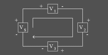
So based on the law applicable kirchoff voltage:

Example Kirchoff Voltage
Determine the voltage of the unknown in the following series!
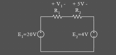
Answer:
By applying Kirchhoff's voltage law is

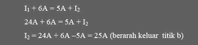
Example Kirchoff Arus
Determine the flow of the unknown from the image below!


X . IIIIII DARLINGTON PAIR TO DRIVE MOTOR DC CIRCUIT
A normal variable resistor cannot directly control the speed of a motor since motors draw large amounts of current which would burn out the potentiometer. Instead, the small amount of current that the potentiometer can pass can be amplified into order to run the motor. This amplification can be achieved using Darlington Pair of transistors.

Darlington Pair to Drive DC motor Circuit
Pin-out BFY61 & TIP31C Transistor
The circuit above shows a linear potentiometer connected Between Vs and 0V Such That the voltage at its wiper terminal will of always be somewhere at or Between these two voltages. The small amount of current flowing out of the potentiometer's wiper is amplified by two transistors, connected together in a configuration known as a 'Darlington pair'. The current from the potentiometer is amplified by the first transistor, and then again by the second transistor, greatly Increasing the amount of current That cans be controlled by the potentiometer.
There are, however, a couple of disadvantages of this simple circuit. Firstly, about 0.7V is lost in EACH of the transistor, so the maximum voltage cans That ever be applied to the motor is Vs - 1.4V. Secondly, the transistors are not absolutely linear so the change in motor speed for a given rotation of the potentiometer will from some more subtle in the middle of its range. Because a motor is an inductive load, it will from Produce a 'back-emf' Could the which damage to the second transistor. The 1N4148 signal diode prevents this damage by shorting out the back-emf.
The power supply for this circuit should preferably be un-smoothed (i.e. directly from the power supply rectifier). This helps prevent the motor 'sticking' at low speeds. With the TIP31C transistor given, the maximum power supply voltage may be 60V and the maximum motor current consumption may be 3A.
X . IIIIIII AUDIO PICK LEVEL INDICATOR BY OP- AMP
simple circuit PEAK indicator of foliage of the musical signal. This circuit was designed to provide a valuable test equipment tool for sound reinforcement systems like sound amplifiers and the like. The circuit is formed by an input buffer and ac to dc voltage converter (IC1A) feeding a window comparator (IC2A, IC2B, IC2C) which illuminates one of three LEDs at a time.

schematic circuit : Audio Peak Level Indicator By Op-Amp
No setup is required: if correct values are used for resistors R3 to R7, LED D1 will illuminate at 0dB input (0.775V RMS), LED D2 at +5dB input (1.378V RMS) and LED D3 at +10dB (2.451V RMS).
The circuit was optimized for low current consumption as it was intended for battery operation. To achieve this, the best arrangement has proven to be the one using two different op-amp types for IC1 and IC2. In fact the LM393 IC was not operating satisfactorily as dot-mode LED driver, whereas the LM324 was unable to charge C2 in the linear way, as expected. Therefore, the final circuit is some op-amp wasting, but the small added cost will be quickly compensated by battery savings.
The circuit was optimized for low current consumption as it was intended for battery operation. To achieve this, the best arrangement has proven to be the one using two different op-amp types for IC1 and IC2. In fact the LM393 IC was not operating satisfactorily as dot-mode LED driver, whereas the LM324 was unable to charge C2 in the linear way, as expected. Therefore, the final circuit is some op-amp wasting, but the small added cost will be quickly compensated by battery savings.
List Component:
R1    : 300K         D1,D2,D3 : LEDs
R2    : 1M2          IC1      : LM393
R3    : 510K         IC2      : LM324
R4    : 220K         IC3      : 78L05
R5    : 91K          SW1      : SPST  Toggle or Slider Switch
R6    : 160K         B1: 9V  PP3 Battery
R7    : 56K
R8,R9 : 100R
R10   : 220R
C1    : 100nF
C2    : 1µF/63V
C3    : 10µF/25V
X . IIIIIIII Driver (Activator) Playback TV
This is an efficient flyback driver for modern cylindrical rectified television flybacks. Frequency range can be increased using multiposition switch for other values of C3 capacitor, for example 2 nF for 80KHz-200000KHz, but didn't found flybacks with so high resonant frequencies, in addition with higher values of c3 , eg 200nF, 2uF the frequency will drop making possible the use of ignition coils, and rectified power transformers @50Hz to charge high voltage electrolitic caps at 300-400V).

The 555 is wired as an astable and the capacitor is charged only through the 4,7Kohm trimmer (notice the diode) and discharged only through the 2.2 Kohm trimmer, making the duty cycle full adjustable. The square wave is then feed in a totem pole made up of a 2N3904 and a 2N3906, which are cheap, and easy to find. The totem pole ensures the gate being charged and discharged very fast (approx 50nS). The IRF840 is a cheap reliable and powerful power mosfet, it has current capability of 8 A continuous and 32A pulse, 800V drain source voltage, protecting internal zener diode. There is a snubbing network to ensure that voltage spikes are kept low (unless the insulation of the transformer start to leak) protecting both transistors and 555 IC. 100 ohm is a compromise between decay time and voltage spike.
Note:
The flyback driven in this way can supply a significant current, aldough the heart fibrillation starts at 30mA I recommend caution to avoid painful arc-burns. The arc is a hot plasma, never operate the circuit in presence of flammable substances. Charging high voltage capacitors is a serious life threat, so if you arent unexperienced just draw arcs and no more This device when rectified generates static voltage that can be a little annoying
X . IIIIIIIII the motor speed control using PWM
So-called PWM or Pulse Modulation Witdh is a technique often used to control a load, for example, is the DC motor speed control, PWM techniques are often used.
Usually to make a simple PWM (for practice or introduction PWM) of the hobbyist to use some of the circuit made of Op-Amp, which consists of Schmitt Trigger circuit, integrator and comparator.

Diagram of PWM Controller
Schmitt Trigger function that produces a square wave will be converted by the integrator sawtooth wave or commonly also called Ramp, and Ramp compared with a reference voltage that can be changed much voltage. So the result is a PWM output.

Schematic circuit Low Side PWM Motor/Light Controller
 Schematic circuit High Side PWM Motor/Light Controller
These two schematics are variations on another PWM circuit. The diagrams are for 12V operation only and there are high side (common ground) and low side (common +12V) versions. The low side version of the circuit uses an N Channel FET, the high side version of the circuit uses a P Channel FET. N Channel devices tend to handle more current than P Channel devices, they are also less expensive. The high side version of the circuit is useful when one side of the load has to be grounded.
This circuit can switch a fairly high amount of current, an IRFZ34N MOSFET can handle over 35 Amps if connected to a proper heat sink. Higher power FETs, such as the IRFZ48N or IRF1010Z can be substituted if even larger currents are required. It is also possible to connect multiple FETs in parallel for even more current capacity. Always use thermally conductive grease between the FET and the heat sink, and remember that the heat sink is electrically live.
Inductive loads (motors) may require special care since they can generate large voltage spikes that can damage the MOSFET. Replacing the 1N4002 with a fast recovery diode may help absorb the reverse voltage kick when driving an inductive load such as a motor. If you use these circuits for experiments with electric vehicles, be sure to install a circuit breaker in series with the battery, the circuit breaker should be easy to reach by the driver. This is especially important due to the fact that when MOSFETs fail, they often short out, leaving the motor on at full speed.
X . IIIIIIIIII LM 390 simple 2 - way intercom circuit
This is a very simple two way intercom circuit based on a LM390 audio amplifier circuit . the intercom circuit is a stand-alone electronic communications system intended for limited or private dialogue. For this circuit you can use a 8 ohms speaker, one for each station and require a 6 volts dc power supply. Gain control can be done by capacitively coupling a resistor (or FET) from pin 6 to ground.

LM390 Simple 2-Way intercom Circuit

LM390 Pin out
The LM390 Power Audio Amplifier is optimized for 6V, 7.5V, 9V
operation into low impedance loads. The gain is internally set at 20 to
keep the external part count low, but the addition of an external
resistor and capacitor between
pins 2 and 6 wil increase the gain to any value up to 200. The inputs
are ground referenced while the output is automatically biased to one
half the supply voltage.
X . IIIIIIIIIII circuit remote control
This is a remote control circuit
employing ultrasonic signals. The ultrasonic transmitter circuit is
build around IC1(NE 555). IC1 is an astable multi vibrator operating at
40KHz.The output of IC1 is amplifier the complementary pair of
transistors ( Q1 & Q2) and transmitted by the ultrasonic transmitter
K1. The switch S1 is used activate the transmitter.

Schematic circuit remote Control ultrasonic
Note:
The ultrasonic receiver uses an sensor transducer (K2) to sense the ultrasonic signals. When an ultrasonic signal is falling on the sensor, it produces a proportional voltage signal at its output. This weak signal is amplified by the two stage amplifier circuit comprising of transistors Q3 and Q4.The output of the amplifier is rectified by the diodes D3 & D4.The rectified signal is given to the inverting input of the opamp which is wired as a comparator. When ever there is an ultrasonic signal falling on the receiver, the output of the comparator activates the transistors Q5 & Q6 to drive the relay. In this way the load connected via the relay can be switched. The diode D5 is used as a free wheeling diode.
Note:
- switch S1 can be a push button switch.
- The preset R16 can be used to adjust the sensitivity of the receiver.
- The frequency of the ultrasonic signal can be varied by adjusting the preset R17.Adjust it for optimum performance.
The ultrasonic receiver uses an sensor transducer (K2) to sense the ultrasonic signals. When an ultrasonic signal is falling on the sensor, it produces a proportional voltage signal at its output. This weak signal is amplified by the two stage amplifier circuit comprising of transistors Q3 and Q4.The output of the amplifier is rectified by the diodes D3 & D4.The rectified signal is given to the inverting input of the opamp which is wired as a comparator. When ever there is an ultrasonic signal falling on the receiver, the output of the comparator activates the transistors Q5 & Q6 to drive the relay. In this way the load connected via the relay can be switched. The diode D5 is used as a free wheeling diode.

Pin Connection Ic NE 555


- Ground, is the input pin of the source of the negative DC voltage
- Trigger, negative input from the lower comparators (comparator B) that maintain oscillation capacitor voltage in the lowest 1 / 3 Vcc and set RS flip-flop
- Output, the output pin of the IC 555.
- Reset, the pin that serves to reset the latch inside the IC to be influential to reset the IC work. This pin is connected to a PNP-type transistor gate, so the transistor will be active if given a logic low. Normally this pin is connected directly to Vcc to prevent reset
- Control voltage, this pin serves to regulate the stability of the reference voltage negative input (comparator A). This pin can be left hanging, but to ensure the stability of the reference comparator A, usually associated with a capacitor of about 10nF to berorde pin groun
- Threshold, this pin is connected to the positive input (comparator A) which will reset the RS flip-flop when the voltage on the capacitor from exceeding 2 / 3 Vc
- Discharge, this pin is connected to an open collector transistor Q1 is connected to ground emitternya. Switching transistor serves to clamp the corresponding node to ground on the timing of certain
- Vcc, pin it to receive a DC voltage supply. Usually will work optimally if given a 5-15V. the current supply can be seen in the datasheet, which is about 10-15mA.
X . IIIIIIIIIIII Infra Red Remote Tester
The circuit is very effective to test the remote controls what still works or not, the remote record will be tested using infra red. Examples of the TV remote, AC and others. Please try I am sure 100% will be successful.
 Rangkaian Remote Tester
The workings of the circuit is very simple, when the infra red
sensor receive infrared signals pin 2 sensor will produce a voltage,
this voltage will drives the PNP transistor so that the LED lamp and
piezo disc (BZ) is active. for the power supply you can use a 9 volt
battery and then use IC 7805 or use 1.5 volt batteries x 3
Following the specification of components installed
- Transistor BC557
- TSOP 1738 Sensor Infra Red
- R1 = 10k ohm ¼ watt Resistor
- R2 = 1k ohm ¼ watt Resistor
- R3 = 1k ohm ¼ watt Resistor
- BZ = piezo disc
- led

Features
- Photodetector and preamplifier circuit in the same casing.
- Receives and amplifies the infrared signal without any external component.
- 5 V output (active at level 0).
- 38 kHz integrated oscillator.
- High sensitivity.
- High level of immunity to ambient light.
- Improved shielding against electrical field interference.
- TTL and CMOS compatibility.
- Applications: infrared remote control.
- Supply: 5 V
- Power consumption: 0.4 to 1.0 mA
- Min. Ee irradiation: 0.35 mW/m2 typ.
- Angle of detection: 90
- Dimensions of the casing (mm): 12.5 x 10 x Thickness 5.8
- Temperature range: -25 C to +85 C
X . IIIIIIIIIIIII The series of Remote Control Toy Car
In this system, radio signals emanated not continue to be raised but only when the controller sends the right / left or forward / backward, that is only a radio frequency that discontinuous,so that the credit delivery frequency radio waves.
The amount of credit that is sent to represent the command post, the forward was represented with 8 credits, left represented with 16 credits, 32 credits right and Backward 64 credits. Commands can be sent is a combination of 2 commands, namely the combination of forward / backward and right / left, as an example can be sent forward and the left, in this case the amount of credit that is sent 24, the Answer of the forward and the balance of 8 the left as many as 16 credits.
 Skema Rangkaian Pemancar Radio Remote Control
 Skema Rangkaian Penerima Radio Remote Control
 Making transformer TX and RX:
Transformer
T1 in series transmitter and recipient, is the same, and must be made.
Transformer was built using plastic koker transformer (spare part radio)
so that the step appears to have 5 channels that can be filled with a wire coil,
as shown in the picture. Wearing this koker facilitate scrolling wire
transformer. If it can not be koker like that, just use the normal.
Koker transformer is small and ferit is also small (3 mm) as the first
assembly is often used for CB 27 MHz radio.
Transformer wire to wire to use in the unloading of koker, and slowly open the wire coil inside the existing wire koker because it is quite smooth and easy to drop out
- coil wire from the foot of the number to 5 feet 4 hours direction (CW) of 3-and-roll at level 1 (line at the bottom line above)
- Scroll through the wire from 1 foot to 2 feet clockwise roll of 4 on the exact level 2.
- Continue to roll (from step 2) clockwise a quarter roll of 3 to 3 feet in three levels. (You can set exactly a quarter roll, because the path that has kokernya be split into 4).
Scroll through the copper wire diameter size of 0.3 - 0.5 mm of 10 quarter roll koker in diameter about 4 mm (which will be released later) is also clockwis
Making coil L2
Scroll through the copper wire diameter of 0.1 mm sizes of 50 on the roll without koker plastic ferit diameter about 3.5 - 4 mm (search item from the plastic material used) is also clockwise. The length of the coil along liputi in 5 mm.
Scroll through the copper wire diameter of 0.1 mm sizes of 50 on the roll without koker plastic ferit diameter about 3.5 - 4 mm (search item from the plastic material used) is also clockwise. The length of the coil along liputi in 5 mm.
X . IIIIIIIIIIIIII LIGHT / DARK SWITCH RELAY
The circuit as shown act as a light detector. Under normal conditions the resistance of the LDR is high, keeping pin 2 low. When light falls onto the LDR the resistance drops to a couple hundred ohms and triggers pin 2 high which biases the base of Q1 via pin 6 and R4 and in turn activates the relay.
 Light/Dark switch Circuit with relay
As you may have notice, the 741 is connected as a voltage comparator. Two voltage dividers
are easy to be found: The first one is the10K resistor and the LDR .
The second one is composed by the two 470 Ohms resistors and the
potentiometer. Both the outputs of the dividers are connected as inputs to the voltage comparator.
The second voltage divider will settle the reference voltage. The first voltage comparator that contains the LDR, will change it's voltage according to the light level. When the voltage across the negative input of the comparator is less than the voltage to the positive input of the comparator, the output is held low. When the voltage on the negative input rises, there will be a time that it becomes greater than or equal to the positive (pre-selected) voltage, and then the output becomes high and the relay through the 2N2222 is actuated.
The second voltage divider will settle the reference voltage. The first voltage comparator that contains the LDR, will change it's voltage according to the light level. When the voltage across the negative input of the comparator is less than the voltage to the positive input of the comparator, the output is held low. When the voltage on the negative input rises, there will be a time that it becomes greater than or equal to the positive (pre-selected) voltage, and then the output becomes high and the relay through the 2N2222 is actuated.
X . IIIIIIIIIIIIIIII 220 volt disco lamp circuit
This disco lamp circuit
is not a voice operated switch (VOX) because this circuit is too dumb
to differentiate between musical sound or human voice. This is rather a
sound activated than voice activated. One interesting application is to control
your disco lighting automatically by the musical sound from high power
amplifier, when the music signal is dominating the sound space. The
disco lamp circuit schematic diagram is shown below.

You can use either moving coil microphone or condenser microphone for this circuit. Make sure the electrolytic capacitor is rated for 16 volt or more. The potentiometer shown in the schematic
diagram is used to adjust the gain of the pre-amplification. You can
adjust this potentiometer to get a proper sound level where the relay
would be activated.
List Componet Of Disco Lamp circuit
- R1 : 22k 1/4 watt resistor
- R2 : 4K7 watt resistor
- R3 : 2K2 watt resistor
- R4,R8 : 10K watt resistor
- R5 : 33K watt resistor
- R6 : 56K watt resistor
- R7 : 1M watt resistor
- Potensio: 50K
- C1 : 470uf/35V electrolytic capacitor
- C2 : 22n ceramic capacitor
- C3 : 100n ceramic capacitor
- C4 : 1Uf/50V electrolyticcapacitor
- D1 - D5 : 1N4007
- D6 : Zener 5.1v
- D7 : 1N4148
- IC : CD 4069
- SCR : FIR 3D
- Mic : Mic Condensor
X . IIIIIIIIIIIIIIIII CAR PARKING SENSOR CIRCUIT USING - INFRA RED LED
This circuit can be used for an assist in parking the car near the garage wall backing up Pls. LED D7 illuminates Pls bumper-wall distance is about 20 cm., D7 + D6 illuminate at about 10 cm. and D7 + D6 + D5 at about 6 cm. In this manner you are alerted Pls approaching too close to the wall.
 Car Parking Sensor circuit
All
distances mentioned before can vary, depending on infra-red
transmitting and receiving LEDs used and are mostly affected by the
color of the reflecting surface. Black surfaces lower greatly the device
sensitivity. Obviously, you can use this circuit in other applications like liquids level detection, proximity devices etc.
Note:
- The infra-red Photo Diode D2, should be of the type incorporating an optical sunlight filter: these components appear in black plastic cases. Some of them resemble TO92 transistors: in this case, please note that the sensitive surface is the curved, not the flat one.
- Avoid sun or artificial light hitting directly D1 & D2.
- If your car has black bumpers, you can line-up the infra-red diodes with the (mostly white) license or number plate.
- It is wiser to place all the circuitry near the infra-red LEDs in a small box. The 3 signaling LEDs can be placed far from the main box at an height making them well visible by the car driver.
- The best setup is obtained bringing D2 nearer to D1 (without a reflecting object) until D5 illuminates; then moving it a bit until D5 is clearly off. Usually D1-D2 optimum distance lies in the range 1.5-3 cm.
R1             : 10K
R2,R5,R6,R9    : 1K
R3             : 33R
R4,R11         : 1M
R7             : 4K7
R8             : 1K5
R10,R12-R14    : 1K
C1,C4          : 1µF/63V
C2             : 47pF
C3,C5          : 100µF
D1             : Infra-red LED
D2             : Infra-red Photo Diode (see Notes)
D3,D4          : 1N4148
D5-7           : LEDs (Any color and size)
IC1            : NE555
IC2            : LM324
IC3            : LM7812
X . IIIIIIIIIIIIIIIIII DIGITAL SPEEDOMETER CIRCUIT
Speedometer Digital
This circuit serves to show the speed of the vehicle in kmph. An opaque disc is mounted on the spindle attached to the front wheel of the vehicle. The disc has about equidistant holes on its periphery. On one side of the disc an infrared LED is fixed and on the opposite
side of the disc, in line with the IR LED, a phototransistor is mounted. IC LM324 is wired as a comparator. When a hole appears between the IR LED and phototransistor, the phototransistor conducts. Hence the voltage at collector of the phototransistor and inverting input of LM324 go ‘low’, and thus output of LM324 becomes logic ‘high’. So rotation of the speedometer cable results in a pulse (square wave) at the output of LM324. The frequency of this waveform is proportional to the speed.
side of the disc, in line with the IR LED, a phototransistor is mounted. IC LM324 is wired as a comparator. When a hole appears between the IR LED and phototransistor, the phototransistor conducts. Hence the voltage at collector of the phototransistor and inverting input of LM324 go ‘low’, and thus output of LM324 becomes logic ‘high’. So rotation of the speedometer cable results in a pulse (square wave) at the output of LM324. The frequency of this waveform is proportional to the speed.
 Skema rangkaian speedometer digital
For a vehicle such as LML Vespa, with a wheel circumference of 1.38 metres, and number of pulses equal to 10 per revolution, we get the relationship:
 This
speedometer can measure up to 99 kmph with a resolution of 1 kmph. The
range can be increased up to 999 kmph by adding another stage consisting
of one each of ICs 7490, 74175, 7447 and a 7-segment display.
This
speedometer can measure up to 99 kmph with a resolution of 1 kmph. The
range can be increased up to 999 kmph by adding another stage consisting
of one each of ICs 7490, 74175, 7447 and a 7-segment display.
X . IIIIIIIIIIIIIIIIIIII how to ensure destruction TV tuner
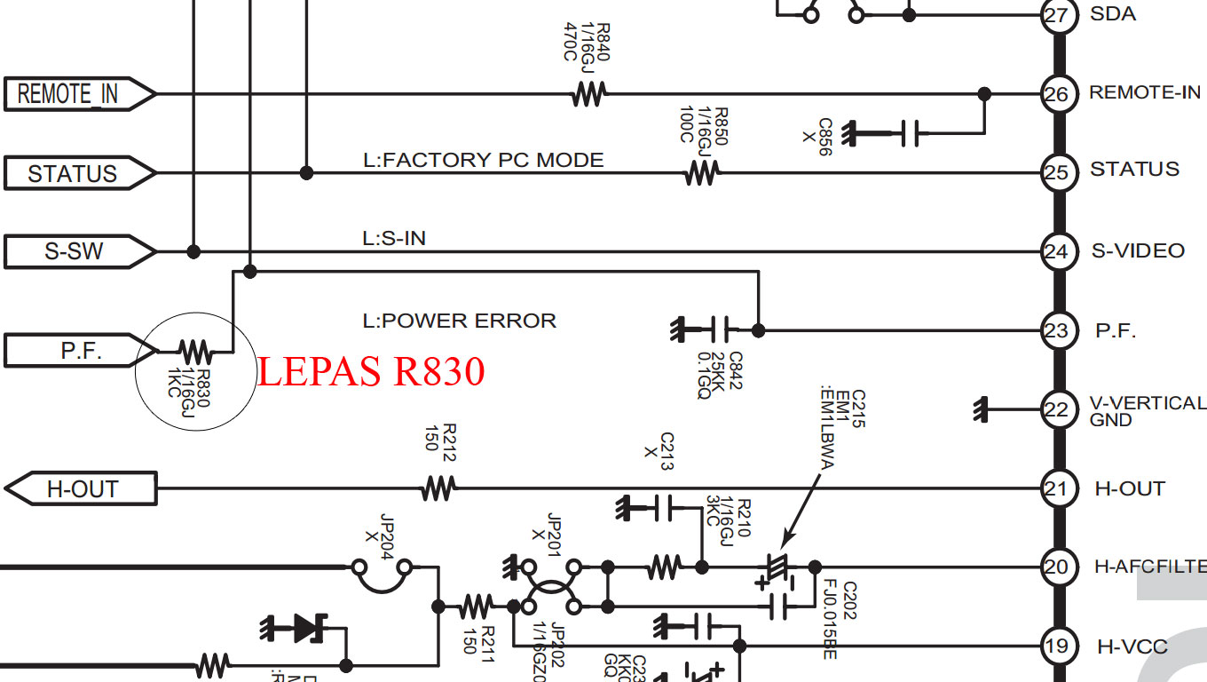
Sometimes we see the damage that using TV Tuner type Frequency Synthesizer (FS) or PLL tuner that can not receive the broadcast. Whereas existing raster, voltage 5V, 32V, SDA and SCL arbitrarily checked normal, so our suspicions lead to damage to the tuner section, but it is better not to rush - rush to replace the tuner, first make sure ... whether the TV tuner completely broken or no......
TV can not receive the broadcast could have been caused by problems in other parts such as Video-IF, ic program, a memory, or the tuner itself. Suspecting tuner damage sometimes we hesitate. Moreover, certain TV tuner is very difficult to find on the market and the price is also quite expensive. To ensure the damage tuner, then we usually wear the following manner:
Remove the tuner are damaged.
Provide a regular tuner or tuner Voltage Synthesizer (VS) and a VR 50K
Meanwhile, with the help of cables for the connections as follows.
Make the connections to the tuner with the Vcc 5v, AGC, IF-out, Gnd.
UHF tuner locks in position only by giving a voltage of 5V on pin-UHF if using the tuner type 3 bandswitch. If using the tuner type 2 band-switch key to give 5v voltage on-sw1 Band and Band-sw 2.
VR one end connected to Gnd and the other to 33V, and the middle leg connected to the pin-VT tuner.
Turn on the TV, and use VR for a way to be twisted around to look for the broadcast.
If the image and sound acceptable means Tuner PLL is really broken.
X . IIIIIIIIIIIIIIIIIIIII game series 7 segment

Skema Rangkaian game 7-segmen
You can play this game alone or with your friends. The circuit comprises a timer IC, two meters of decade and a driver of posting with a posting of segment 7. The play is simple. Like city above, it is a play of marking and the competitor
which marks 100 points quickly (in short stages) is gaining it. To
mark, one with the option to press the S2 switch or S3. Commutate S2,
once pressed, realize against counting in the direction forwards,
whereas the S3 switch helps to count in bottom. Before beginning a
fresh play, and for this matter even a fresh movement, you must press on
the S1 switch to give to zero the circuit. Then, press on the two
switches the ones of, C. - with-D. S2 or S3. On pressing on the switch
S2 or S3, the exits of the BCD of the meter change very quickly and when
you release the switch, last remainders of number locked with the
output of IC2. The locked number of BCD entered the BCD to the decoder
of 7 segments/au conducting IC3 which leads a posting DIS1 of
common-anode. However, you can read this number only when you press on
the S4 switch. The order of the operations to play the (Rangkaian game 7-segmen) game enters, indicate that the `X of two players and Y, are recapitulated below:
- The `X of player starts by pressing temporary contact STRONG CURRENT S1 followed by pressing and release of the S2 switch or S3. Then it supports on the S4 switch to read posting (points) and of the notes in bottom of this number (known as X1) manually.
- The `Y of player also starts by pressing temporary S1 switch followed by the pressing of the S2 switch or S3 and note then in bottom of its points (known as Y1), after having pressed on the S4 switch, exactly of the same mode as made by the first player.
- The `X of player still presses on the S1 switch and repeats the stages shown in stage 1 above and the notes in bottom of its new points (said, X2). He adds these points to his preceding points. The same process is repeated by the `Y of player in his turn.
- The play continues up to the points reached by one of the two totals of players until or exceeds 100, to be declared as gaining.
- Several players can take part in this play, with each one which obtains a chance to mark during its own turn. The assembly can be made using a universal council. Fix posting (LED and posting of segment 7) on the box with the three switches. The supply voltage for the circuit is 5V
X . IIIIIIIIIIIIIIIIIIIIII simple digital voltmeter circuit
Digital voltmeters are instruments that measure voltage or voltage drop in a circuit. They use solid-state components and display values digitally. Typically, digital voltmeters (digital volt meters) are used to locate excessive
resistance that may indicate an open circuit or ground. They are also
used to identify low voltage or voltage drops that may indicate a poor connection.
Digital voltmeters are connected in parallel (and never in series) with
the circuit being tested so that the meter can tap a small amount of
current. The positive lead is connected to the circuits positive side
and the negative lead is connected to the circuits ground. The digital
voltmeters internal resistance is the impedance, which is usually expressed
in ohms per volt. This amount is relatively high in order to prevent
the device from drawing significant current and disturbing the operation
of the circuit being tested. The sensitivity of the current meter and
the value of the series resistance determine the range of voltages that digital voltmeters can measure.
Digital voltmeters can measure a range of alternating current (AC) voltages, direct current (DC) voltages, or both AC and DC voltages. Devices typically display between three and seven digits. Some digital voltmeters can capture minimum and maximum voltages called spike readings.
In the picture below is a series of simple digital voltmeter using the Seven-segment display, this series based ICL7107.The ICL7107 is a 3 1 / 2 digit LED A / D convertor. It contains an internal voltage reference, high isolation Switches analog, sequential control logic, and the display drivers. The auto-zero adjust ensures zero reading for 0 volts input.
 schematic circuit Voltmeter digital
 Schematic of Power Meter For Audio Amplifier
Note:
 Skema Rangkaian 8038 frequency | Signal Generator
 IC 8038 Pinout
One such device is the 8038 a precision waveform generator IC capable of producing sine, square and triangular output waveforms, with a minimum number of external components or adjustments. Its operating frequency range can be selected over eight decades of frequency, from 0.001Hz to 300kHz, by the correct choice of the external R-C components.
The frequency of oscillation is highly stable over a wide range of temperature and supply voltage changes and frequencies as high as 1MHz is possible. Each of the three basic waveform outputs, sine, triangle and square are simultaneously available from independent output terminals. The frequency range of the 8038 is voltage controllable but not a linear function. The triangle symmetry and hence the sine wave distortion are adjustable.
X . IIIIIIIIIIIIIIIIIIIIIIIII stereo tone control saturn with 4 transistors

list Component

 Skema rangkaian audio tone control 2 transistor
quick Data Transistor BC109C
Low current max. 100 mA
Low voltage max. 45 V
Collector-base voltage open emitter 30 V
Collector-emitter voltage open base - 20 V
Peak collector current - 200 mA
total power dissipation Tamb £ 25 °C - 300 mW
DC current gain (hFE ) IC = 2 mA; VCE = 5 V 200 - 800
transition frequency IC = 10 mA; VCE = 5 V; f = 100 MHz 100 - MHz
Pining transistor BC109C

1 emitter
2 base
3 collector, connected to the case
Digital voltmeters can measure a range of alternating current (AC) voltages, direct current (DC) voltages, or both AC and DC voltages. Devices typically display between three and seven digits. Some digital voltmeters can capture minimum and maximum voltages called spike readings.
In the picture below is a series of simple digital voltmeter using the Seven-segment display, this series based ICL7107.The ICL7107 is a 3 1 / 2 digit LED A / D convertor. It contains an internal voltage reference, high isolation Switches analog, sequential control logic, and the display drivers. The auto-zero adjust ensures zero reading for 0 volts input.
 schematic circuit Voltmeter digital
X . IIIIIIIIIIIIIIIIIIIIII POWER METER SCHEMATIC FOR AUDIO AMPLIFIER
This is a simple schematic of audio power meter using LM3915 IC, this schematic can be used to measure the actual output power of your amplifier. For an audio engineer, this schematic Seems to be very helpful, especially for checking of sound system installation and field testing. Due to its logarithmic scale, the wide range of audio output
with only ten scales cans Also be measured. If you take an attention to
the pin number 5 of the LM3915, see That you will from the input is not
yet Rectified. At this input pin, the negative swing will from the
present. However, it is harmless since the current is limited by R1, the
LM3915 earnest therefore respond only to positive cycle.
 Schematic of Power Meter For Audio Amplifier
Note:
When
the speaker resistance is 4Ω, then, make R1=10kΩ, if the resistance of
speaker is 8Ω, make R1=8kΩ, and if the resistance of speaker is 16Ω,
make R1=30kΩ.
The absence of peak detector or the detector will of averages give the circuit a fast
reading of instantenous power, and this Gives us insight of both
average and peak condition. For more readable peak or average
mesurement, you cans use peak or average detector circuit.
X . IIIIIIIIIIIIIIIIIIIIIII 8038 circuit frequency / signal generator
frequency
| Signal Generator circuit is a circuit that produces a variety of
different waveforms at a desired frequency. It can generate Sine waves,
Square waves, Triangular and Sawtooth waveforms as well as other types of output waveforms. There are many "off-the-shelf" waveform generator IC's available and all can be incorporated into a circuit to produce the different periodic waveforms.
 Skema Rangkaian 8038 frequency | Signal Generator
 IC 8038 Pinout
One such device is the 8038 a precision waveform generator IC capable of producing sine, square and triangular output waveforms, with a minimum number of external components or adjustments. Its operating frequency range can be selected over eight decades of frequency, from 0.001Hz to 300kHz, by the correct choice of the external R-C components.
The frequency of oscillation is highly stable over a wide range of temperature and supply voltage changes and frequencies as high as 1MHz is possible. Each of the three basic waveform outputs, sine, triangle and square are simultaneously available from independent output terminals. The frequency range of the 8038 is voltage controllable but not a linear function. The triangle symmetry and hence the sine wave distortion are adjustable.
X . IIIIIIIIIIIIIIIIIIIIIIIII stereo tone control saturn with 4 transistors
Tone Control circuit serves for setting the size of the treble and bass in the sound source. This circuit has a function that is setting the bass level bassing and trebling ie treble level adjustment. The setting is right will bring good quality sound to be heard. Besides the installation of the correct tone contril also determines whether or not the quality of the sound produced.
Tone Control to make the required quality also components - components that have good quality. The following tone control circuit stereo that use only 4 transistor N and the circuit is quite simple but the results are quite good, the tone control is artificial saturn, the character of the bass and treble that produced luamayan good and suranya that produced too clean, suitable for beginners because the installation is very easy and not too sensitive so without regulator even tone control circuit can work well.
Tone Control to make the required quality also components - components that have good quality. The following tone control circuit stereo that use only 4 transistor N and the circuit is quite simple but the results are quite good, the tone control is artificial saturn, the character of the bass and treble that produced luamayan good and suranya that produced too clean, suitable for beginners because the installation is very easy and not too sensitive so without regulator even tone control circuit can work well.
X . IIIIIIIIIIIIIIIIIIIIIIIIII 6 band graphic equalizer circuit using 741 - op amp
This
circuit is 6 Band Graphic Equaliser ,you can adjust sound in low ,mid
and high which circuit used IC 741 Op-Amp. With this circuit you can control and blend frequencies and tones as desired.
Essentially, the circuit consists of an IC 741 whose gain at various freguencies is determined by corresponding potentiometer setting.
Essentially, the circuit consists of an IC 741 whose gain at various freguencies is determined by corresponding potentiometer setting.
The audiblefrequency spectrum is covered
in six steps: 50Hz, 160Hz, 500Hz, 1.6kHz, 5kHz, 16kHz. All
potentiometers are of 100kΩ linear type. The circuit provides adequate
boost / cut for normal use.
power supply for the circuit can be derived from the amplifier / preamplifier itself. The wide rangeof supply voltage (6V-20V) makes the circuit very versatile. Power consumption is negligible.
power supply for the circuit can be derived from the amplifier / preamplifier itself. The wide rangeof supply voltage (6V-20V) makes the circuit very versatile. Power consumption is negligible.
list Component
R1,R2,R3,R4,R5,R6 : 27kΩ     C1: 100n      C6: 300pF
R7:  470kΩ                   C2: 33n       C7: 100uF/16V
R8:  330kΩ                   C3: 10n       C8: 4.7uF/16V
R9:  100kΩ                   C4: 3.3n      C9: 47uF/16V
R10: 4.7kΩ                   C5: 1n        IC1: 741 Op amp
R11: 4.7kΩ
VR1,VR2,VR3,VR4,VR5,VR6: 100kΩ Linear Potentiometers
X . IIIIIIIIIIIIIIIIIIIIIIIIIIII AUDIO CIRCUIT TONE CONTROL 2 TRANSISTOR
Audio tone control circuit based transistors on these provides a maximum cut and boost of around 10dB at 10K and 50Hz.
 Skema rangkaian audio tone control 2 transistor
The first BC109C transistor is acting as a buffer.
It provides the circuit with a high input impedance, around 250k has a
voltage gain of slightly less than unity. As the Baxendall tone control circuit is a passive design, all audio frequencies are attenuated. The position of the controls and reactance of the capacitors
alters the audio response. The last transistor provides a slight boost
of about 3x. The output is designed to feed an amplifier with input
impedance of 10k to 250k. Both tone controls should be linear type Potentiometers.
quick Data Transistor BC109C
Low current max. 100 mA
Low voltage max. 45 V
Collector-base voltage open emitter 30 V
Collector-emitter voltage open base - 20 V
Peak collector current - 200 mA
total power dissipation Tamb £ 25 °C - 300 mW
DC current gain (hFE ) IC = 2 mA; VCE = 5 V 200 - 800
transition frequency IC = 10 mA; VCE = 5 V; f = 100 MHz 100 - MHz
Pining transistor BC109C
1 emitter
2 base
3 collector, connected to the case
X . IIIIIIIIIIIIIIIIIIIIIIIIIII Traffic light circuit 20 channel the base 74 LSXX
This electronic project (Rangkaian Traffic light) based only on 74LSxx family and IC 555 as clock source. It's a digital logic circuit. To build rangkaian Traffic Light Control you don't need microcontroller programming.
 Gambar Skema Rangkaian Traffic light
notes:
- The low output go in sequence from 1 - 0 and back to 1 -0
- At the clock rate of the 555 timer
- c3 = 1uf to 10uf depending on the rate of change desured
- R2 (Variable resistor) in use to determine the timer

X . IIIIIIIIIIIIIIIIIIIIIIIIIII Antenna tuning circuit
This is a series of antenna-tuning
circuit or circuits for transmitting antenna placement SW 3-30 MHz wave
/ short wave 3-30 Mhz. If the placement is just right then the maximum energy
from the transmitter will send out all the antenna through sehinnga
nothing is wasted. To get a clear picture of the circuit is click on the
picture below.
 Skema Rangkaian Penala Antena
This transmacth circuit function is to locate an appropriate impedance between the transmitting antenna that occurred in the ratio 1:1 SWR reading it, because in this placement is associated with a series of SWR / standing wave ratio. Thus the purpose of 1:1 is the one that came out was also one emitted by the antenna instead of just half saja.Impedansinya generally is 50 Ohm. With this circuit the maximum power that can pass this circuit is 50 Watt.
About SWR meter
The SWR meter or VSWR (voltage standing wave ratio) meter measures the standing wave ratio in a transmission line. This is an item of radio equipment used to check the quality of the match between the antenna and the transmission line.
 SWR Meter Installation
.jpg)
The VSWR meter should be connected in the line as close as possible to the antenna. This is because all practical transmission lines have a certain amount of loss, causing the reflected power to be attenuated as it travels back along the cable, and producing an artificially low VSWR reading on the meter.
 Skema Rangkaian Penala Antena
This transmacth circuit function is to locate an appropriate impedance between the transmitting antenna that occurred in the ratio 1:1 SWR reading it, because in this placement is associated with a series of SWR / standing wave ratio. Thus the purpose of 1:1 is the one that came out was also one emitted by the antenna instead of just half saja.Impedansinya generally is 50 Ohm. With this circuit the maximum power that can pass this circuit is 50 Watt.
About SWR meter
The SWR meter or VSWR (voltage standing wave ratio) meter measures the standing wave ratio in a transmission line. This is an item of radio equipment used to check the quality of the match between the antenna and the transmission line.
 SWR Meter Installation
SWR Meter Pic
The VSWR meter should be connected in the line as close as possible to the antenna. This is because all practical transmission lines have a certain amount of loss, causing the reflected power to be attenuated as it travels back along the cable, and producing an artificially low VSWR reading on the meter.


use Switching Power Supply is the Power Amplifier TDA7294 GainClone To drive a speaker canon pro 10 ''. The result is quite satisfactory, the same as using a regular iron transformer.


rangkaian power amplifier mobil stereo


X . IIIIIIIIIIIIIIIIIIIIIIIIIIIIIIII HOW TO FIX THE BROKEN OCL POWER AMPLIFIER
This type of OCL power amplifier is 60 watts and above general and widely used in active speaker and is also sold in stores - electronics store in the form of a series of prefabricated and pcb empty.Damage to the power amplifier OCL is usually caused by a transistor that died due to heat (over heat), short circuit speaker cables and speaker coil burning for not being able to handle the power generated power amplifier. in the case of power OCL that uses transistors jengkol MJ2955 and 2N3055, damage caused short circuit the speaker wires can cause transformer power supply also caught fire when the supply voltage of positive and negative is not installed fuse (fuse) for transistor jengkol the type of degradation there are two kinds. The first is general damage that end total (when the transistor is tested with multitester, pointer does not move at all) and the second is in the form of short circuit or shorted (when the transistor is tested with multitester, deviating the needle fully to the right). in the second case is what can cause the power supply transformer burned.to find which components are damaged, please refer to the picture. the arrow shows the components that are easily damaged


Image series of OCL Power AmplifierComponent Test Method:
How to test the R15 and R16: remove one leg of the circuit and then measuring using multitester on a scale of 1Ω or 10Ω. if it does not move, replace it with a new one.
How to test the diodes: Remove one leg diode from the circuit board and then measuring foot - feet using mulitester by way of flipping - turn the plug at the foot of the anode and cathode. if the needle deviate multitester full right or not move at all when the plugs inverted - turning position, replace the diode with a new one.
To test transasistor: remove the transistor from circuit boards, point multitester switch on and test the foot 1KΩ transistor using multitester. For NPN transistors position multitester black jack is located at the base while the red ones on move - move between the collector and emitter then see the pointer on multitester. If the transistor is still good, the needle will deviate slightly to right of the midline. and when the position is reversed ie plugs multitester red plugs at the base while the black jack move - move between the collector and emitter, the pointer does not move (For PNP transistor instead).
If the power amplifier using IC 741, IC replace it if all components in the normal state.
How to Test the Transistor
If all damaged components have been replaced, now is the time to test the circuit. connect the power amplifier to the speakers. If your stereo power amplifier while you have only one unit of the speakers, plug the speaker cable to the positive and negative output L in R (Ground is not needed) and connect it to the power supply circuit. use a relatively small voltage 12V first instance and then press the power button and then listen to the sound on the speakers. if heard a buzzing sound, turn off and then check whether there are upside component installation or transistor swapped positions between NPN and PNP. correct me if there is something wrong and then try to turn back. If the hum is not audible, using finger touch input cable. If you hear a "brrrttt ..." means the power amplifier is already ready for use again. good luck! .
X . IIIIIIIIIIIIIIIIIIIIIIIIIIIIIII LED power indicator audio amplifier
LED Indicator Daya Audio Amplifier
This
circuit, connected to the loudspeaker output of an audio amplifier,
will indicate the instantaneous output power delivered to the
loudspeaker(s) by means of six LEDs illuminating one after another by
voltage values increasing little by little, providing the visual
impression of a luminous bar or column, increasing and decreasing in height following the increase and decrease of the signal’s level.
Notes:- The output power indicated by each LED must be doubled when 4 Ohms loads are driven.
- The circuit can be adapted to suit less powerful amplifiers by reducing the number of LEDs and related voltage dividers.
R1: 220R 1/2W Resistor
R2,R5,R6,R8: 100R 1/4W Resistors
R10,R12,R14: 100R 1/4W Resistors
R3: 220R 1/4W Resistor
R4,R7: 330R 1/2W Resistors
R9: 560R 1/2W Resistor
R11: 820R 1/2W Resistor
R13: 1K2 1/2W Resistor
D1: 1N4004 400V 1A Diode
D2,D4,D6: BZX79C2V7 2.7V 500mW Zener Diodes
D3,D5,D7,D8,D9,D10 Red LEDs (Any dimension and shape) (See Notes)
The input signal is first rectified by D1 and then sent to six different voltage dividers, one for each LED. In this way, the indication provided by the LEDs illumination of this “Power Display”, will be related to the instantaneous power sunk by the whole loudspeaker cabinet. Six output power levels are displayed by the LEDs in a 2W - 80W range (no setup required). Each nominal power level indication into 8 Ohms load is reached when the respective LED illuminates at full brightness.

X . IIIIIIIIIIIIIIIIIIIIIIIIIIIIIIIIII Audio circuit TV video LED

sample Tube TV :


SHARP PROTECT

D603 heaterD607, D608 ABLD605 B 185VD1091 B 9VD204 B 5V tunerD203 B 33V tunerD1010 AC detectorR523 Vertical SyncQ603 C3198 heater6 pin ic IXB226 protect normal AC detector measured 3.6V7 pin ic IXB226 main protect normal measured 3.67V15 pin ic IXB226 protect normal 0.46V measured vertical syncronusprotect analysis:1. tegangn drop in the cathode leg D603 heater below 17.9V, because elco C602 4.7uF / 50V down capasitas2. there is no voltage 185V / AC measurable because of the dryness of elco C604 33uF /250V, breaking R fuse R621 4.7 ohm3. shorted 33V zener diode D201 / C206 10uF elco capasitas downs / 50V4. dropnya B 5V voltage tuner for supplay transistor Q751 D468 is not normal work5. dropnya 9V on out ic 601 090RDA1, because elco 470uf C643 / 16V down capasitas / damage ic 6016. damage ic vertical AN15525 501 for short / short circuit7. C601 563 short / her foot off one could also lead to protect8. The regulator output ACmatic who drop because of falling capasitas elco C719 33uF / 50V / 120K rise in the value of R 702, R705 0.82 ohm 1watt, R706 0.22ohm 1watt cause ACV sensor detector works for 14V voltage drop9. damage to protect the diode sensor can also cause a short circuit protect10. shorted horizontal yoke / burning11. flyback half shorted secondary output of all drop12. The tuner can also cause a short-circuit protected.


Tidak ada komentar:
Posting Komentar