some energy and data transmission channel media and his presentation in energy transmission lines and data are controlled manually go to energy transmission channels and data are controlled semi-automatically for up in energy transmission lines and data are controlled automatically AMNIMARJESLOW GOVERNMENT 913204710250017 XI XAM PIN PING HUNG CHOP 02096010014 LJBUSAW FOR THEN " Thankyume Of Lord Jesus Blessing going up Tower A Turn off and Tower AXO on/off and then if the delivery Tower Q on auto timer JS ___ PIT slope Cell turn over transmission e- WET ___ Gen. Mac Tech zone JS transmission XOW
In the control and transmission lines and measurement measurements both manually and automatically is a common thing if we want the value of the results of the display that is very good both in terms of efficiency and in terms of effectiveness. a display does not mean only what is visible or a monitor but a display has to do with the performance of a system of energy transmission channels that is controlled and measurable even if that energy can be controlled again through the transmission channel media that we might find in generations what will come when that energy can be measured and controlled into a form of energy that we can use again or we can say use full energy in an existing transmission media channel used in the earth in the 21st and 22nd centuries: some of the energy and data transmission media currently available: energy transmission channels and data through water energy and data transmission channels through oil energy and data transmission channels through electrons energy and data transmission channels through light energy and data transmission channels through the wind while control and measurement can be done: energy transmission channels and data are controlled manually, energy transmission channels and data are controlled semi-automatically, energy transmission channels and data are controlled automatically.
energy transmission lines and the above data will experience significant differences when practicing because it has become a media or component and not just an ideal concept, especially in energy pressure and cross-sectional area and the amount of data that can be generated or sent is also accepted, even some hold techniques and delay is different for the transmission line media above. we usually find water, oil and wind transmission lines in the aviation and automotive industries, namely manually controlled concepts: gas levers and brake levers. some are controlled semi-automatically but use control power through electronic and electric systems as instruments and controls. now let's see what about the channels of energy transmission media with electrons as well as light, both of these energy are controlled and measured usually semi-automatically and automatically that is using electronic components quite capable such as: Diodes, Transistors, Photo Diodes, Photo Transistors, Optical Fiber, Solid state driver is also an electron transformer . future developments are emphasized in speed, resistant to certain pressures and vibrations, hold processes and proper delay (memory Concept), also Big data and Big energy generated for a long e-WET (Work - Energy - Time) process and sure.
LOVE & LIGHTING
AMNIMARJESLOW GOV. MAC TECH
____________________________________
ADAPTER LIVE : 020 96010 014 LJBUSAW
Transmission media is a pathway that carries the information from sender to receiver. We use different types of cables or waves to transmit data. Data is transmitted normally through electrical or electromagnetic signals.
An electrical signal is in the form of current. An electromagnetic signal is series of electromagnetic energy pulses at various frequencies. These signals can be transmitted through copper wires, optical fibers, atmosphere, water and vacuum Different Medias have different properties like bandwidth, delay, cost and ease of installation and maintenance. Transmission media is also called Communicationchannel.
Types of Transmission Media
Transmission media is broadly classified into two groups.
Wired or Guided Media or Bound Transmission Media: Bound transmission media are the cables that are tangible or have physical existence and are limited by the physical geography. Popular bound transmission media in use are twisted pair cable, co-axial cable and fiber optical cable. Each of them has its own characteristics like transmission speed, effect of noise, physical appearance, cost etc.
Wireless or Unguided Media or Unbound Transmission Media: Unbound transmission media are the ways of transmitting data without using any cables. These media are not bounded by physical geography. This type of transmission is called Wireless communication. Nowadays wireless communication is becoming popular. Wireless LANs are being installed in office and college campuses. This transmission uses Microwave, Radio wave, Infra red are some of popular unbound transmission media.
The data transmission capabilities of various Medias vary differently depending upon the various factors. These factors are:
1. Bandwidth. It refers to the data carrying capacity of a channel or medium. Higher bandwidth communication channels support higher data rates.
2. Radiation. It refers to the leakage of signal from the medium due to undesirable electrical characteristics of the medium.
3. Noise Absorption. It refers to the susceptibility of the media to external electrical noise that can cause distortion of data signal.
4. Attenuation. It refers to loss of energy as signal propagates outwards. The amount of energy lost depends on frequency. Radiations and physical characteristics of media contribute to attenuation.
Transmission & Distribution
__________________________________________________________________________________
For Transmission and Distribution operations, the drone serves a variety of near-term needs when readily accessible . While the applications are endless and new uses for drones are discovered frequently, let’s look at a few common scenarios .
Transmission Tower Spot Check
Imagine getting a call about a problem with a transmission tower. Without a drone, you order a lineman to go up the tower to inspect the issue, which is dangerous work to begin with. Adding to the obstacles, the only way to get to the tower might be through difficult terrain which is only accessible by way of private property, or the tower is above a line of trees, obstructing your view from the ground.
With traditional means, it may take a couple days to obtain permission to walk across private property and to schedule a small crew to trek to the tower and run an inspection.
With a drone and licensed pilot readily available, this can be accomplished in a matter of minutes. Drones can be used in areas too close to trees or homes for helicopters and in areas that are too difficult to access for ground patrols. There are no hazardous man-hours involved. And you get a clean look at the tower in real time, allowing your team to properly diagnose the problem and suggest a remedy before you even leave the site.
Regular Ground Patrols
During routine maintenance, a lineman sees a potential issue with a tower. A utility company that has trained and outfitted their ground patrol teams with drones can direct that lineman to get a better look at the possible defect without climbing or using bucket trucks. When a team member visually identifies a possible defect, they can quickly deploy a drone to get a higher level of detail, better classify the problem, and determine the best course of action, all while avoiding hazardous man hours.
Substation Upgrades, Maintenance, and Inspection
A problem is reported at a substation. Although easily accessible, substations pose a special challenge because the substation has to be turned off for a human to do the inspection. In rare situations, this can even lead to a brief power outage for customers.
Storm Restoration
A tornado has come through and damaged several towers in its path. Rather than putting men on foot to assess the damage across miles of terrain, you grab the drone and do a survey of the area. With the proper software, the photos are uploaded and stitched together, creating one cohesive map. You’re able to see the entire path of destruction and key in on the damaged areas, allowing you to quickly and efficiently plan recovery measures.
These are some well-known scenarios, but the applications of having a drone and UAV (unmanned aircraft vehicle) pilot on site for transmission and distribution are endless. As the only drone operator at IPL, Dorsett gets new requests on a weekly basis.
Drones can provide safe, efficient inspections and data collection for businesses in alternative and traditional energy. Trained pilots and experienced data analysts use drone technology to drastically reduce inspection time, save labor costs and reduce hazardous man hours, while providing higher quality data that enables companies to maximize energy production.
There are a few ways that these types of inspections are typically completed today: manually, using climbing, bucket trucks or long-range photography (for wind); or by helicopter. Clearly, manual inspections involving climbing or using buckets introduce hazards that are avoided with drones. And ground-based data collection typically lacks the efficiency, detail, and flexibility that a drone can provide. Helicopters can capture data quickly and over large areas of land, but are often expensive, can’t operate near residential areas, and can’t capture images from the optimal angle or distance.
Drone – An unmanned aircraft that is guided remotely. Also known as an unmanned aerial vehicle (UAV). Part 107 – Also known as the FAA’s Small UAS (Unmanned Aerial Systems) Rule, which requires commercial drone operators to obtain remote pilot certification, register UAS vehicles, and comply with all FAA rules. Photogrammetry – The practice of using photography in surveying and mapping to create data capable of measuring distances between objects. Ortho mosaic – a detailed, accurate photo representation of an area, created out of many photos that have been stitched together and geometrically corrected (“orthorectified”) so that it is as accurate as a map. Thermal Imaging – A technique of using the heat given off by an object to produce an image of it Topographic Modeling – the process of representing a location that is true to the shape and features of the surface of the earth. Site Shading Assessment – Site shading analysis exhibits the effect of nearby vegetation growth, topography and infrastructure shading obstructions. The site’s geographical location and seasonal sun positioning are referenced to graph potential shading impacts over the course of the year. LAANC – Low Altitude Authorization & Notification Capability – the system the FAA built to be able to grant near-real-time authorizations for the vast majority of UAS operations. BVLOS – Stands for Beyond the Visual Line of Sight, an FAA rule that prohibits drone operators from flying a drone beyond what they can see with a naked eye. Energy Off takers – A party to an off take agreement, a common agreement in natural resource development where there is some guaranteed minimum level of profit.
Big Data and Big Analytics
Fiber Optic Transfer Energy and Data
Display Control of Performance on Channel energy Transmission with e- Computer
_______________________________________________________________________________
In computing, computer performance is the amount of useful work accomplished by a computer system. Outside of specific contexts, computer performance is estimated in terms of accuracy, efficiency and speed of executing computer program instructions. When it comes to high computer performance, one or more of the following factors might be involved:
The performance of any computer system can be evaluated in measurable, technical terms, using one or more of the metrics listed above. This way the performance can be
Compared relative to other systems or the same system before/after changes
In absolute terms, e.g. for fulfilling a contractual obligation
Whilst the above definition relates to a scientific, technical approach, the following definition given by Arnold Allen would be useful for a non-technical audience:
The word performance in computer performance means the same thing that performance means in other contexts, that is, it means "How well is the computer doing the work it is supposed to do?"
Performance engineering within systems engineering, encompasses the set of roles, skills, activities, practices, tools, and deliverables applied at every phase of the systems development life cycle which ensures that a solution will be designed, implemented, and operationally supported to meet the performance requirements defined for the solution.
Performance engineering continuously deals with trade-offs between types of performance. Occasionally a CPU designer can find a way to make a CPU with better overall performance by improving one of the aspects of performance, presented below, without sacrificing the CPU's performance in other areas. For example, building the CPU out of better, faster transistors.
However, sometimes pushing one type of performance to an extreme leads to a CPU with worse overall performance, because other important aspects were sacrificed to get one impressive-looking number, for example, the chip's clock rate (see the megahertz myth).
Application performance engineering
Application Performance Engineering (APE) is a specific methodology within performance engineering designed to meet the challenges associated with application performance in increasingly distributed mobile, cloud and terrestrial IT environments. It includes the roles, skills, activities, practices, tools and deliverables applied at every phase of the application lifecycle that ensure an application will be designed, implemented and operationally supported to meet non-functional performance requirements.
Availability of a system is typically measured as a factor of its reliability - as reliability increases, so does availability (that is, less downtime). Availability of a system may also be increased by the strategy of focusing on increasing testability and maintainability and not on reliability. Improving maintainability is generally easier than reliability. Maintainability estimates (Repair rates) are also generally more accurate. However, because the uncertainties in the reliability estimates are in most cases very large, it is likely to dominate the availability (prediction uncertainty) problem, even while maintainability levels are very high.
Response time is the total amount of time it takes to respond to a request for service. In computing, that service can be any unit of work from a simple disk IO to loading a complex web page. The response time is the sum of three numbers:
Service time - How long it takes to do the work requested.
Wait time - How long the request has to wait for requests queued ahead of it before it gets to run.
Transmission time – How long it takes to move the request to the computer doing the work and the response back to the requestor.
Most consumers pick a computer architecture (normally IntelIA32 architecture) to be able to run a large base of pre-existing, pre-compiled software. Being relatively uninformed on computer benchmarks, some of them pick a particular CPU based on operating frequency (see megahertz myth).
Some system designers building parallel computers pick CPUs based on the speed per dollar.
Channel capacity
Channel capacity is the tightest upper bound on the rate of information that can be reliably transmitted over a communications channel. By the noisy-channel coding theorem, the channel capacity of a given channel is the limiting information rate (in units of information per unit time) that can be achieved with arbitrarily small error probability. Information theory, developed by Claude E. Shannon during World War II, defines the notion of channel capacity and provides a mathematical model by which one can compute it. The key result states that the capacity of the channel, as defined above, is given by the maximum of the mutual information between the input and output of the channel, where the maximization is with respect to the input distribution.
Latency is a time delay between the cause and the effect of some physical change in the system being observed. Latency is a result of the limited velocity with which any physical interaction can take place. This velocity is always lower or equal to speed of light. Therefore, every physical system that has spatial dimensions different from zero will experience some sort of latency.
The precise definition of latency depends on the system being observed and the nature of stimulation. In communications, the lower limit of latency is determined by the medium being used for communications. In reliable two-way communication systems, latency limits the maximum rate that information can be transmitted, as there is often a limit on the amount of information that is "in-flight" at any one moment. In the field of human-machine interaction, perceptible latency (delay between what the user commands and when the computer provides the results) has a strong effect on user satisfaction and usability.
Computers run sets of instructions called a process. In operating systems, the execution of the process can be postponed if other processes are also executing. In addition, the operating system can schedule when to perform the action that the process is commanding. For example, suppose a process commands that a computer card's voltage output be set high-low-high-low and so on at a rate of 1000 Hz. The operating system may choose to adjust the scheduling of each transition (high-low or low-high) based on an internal clock. The latency is the delay between the process instruction commanding the transition and the hardware actually transitioning the voltage from high to low or low to high.
System designers building real-time computing systems want to guarantee worst-case response. That is easier to do when the CPU has low interrupt latency and when it has deterministic response.
In computer networking, bandwidth is a measurement of bit-rate of available or consumed data communication resources, expressed in bits per second or multiples of it (bit/s, kbit/s, Mbit/s, Gbit/s, etc.).
Bandwidth sometimes defines the net bit rate (aka. peak bit rate, information rate, or physical layer useful bit rate), channel capacity, or the maximum throughput of a logical or physical communication path in a digital communication system. For example, bandwidth tests measure the maximum throughput of a computer network. The reason for this usage is that according to Hartley's law, the maximum data rate of a physical communication link is proportional to its bandwidth in hertz, which is sometimes called frequency bandwidth, spectral bandwidth, RF bandwidth, signal bandwidth or analog bandwidth.
Throughput
In general terms, throughput is the rate of production or the rate at which something can be processed.
In communication networks, throughput is essentially synonymous to digital bandwidth consumption. In wireless networks or cellular communication networks, the system spectral efficiency in bit/s/Hz/area unit, bit/s/Hz/site or bit/s/Hz/cell, is the maximum system throughput (aggregate throughput) divided by the analog bandwidth and some measure of the system coverage area.
In integrated circuits, often a block in a data flow diagram has a single input and a single output, and operate on discrete packets of information. Examples of such blocks are FFT modules or binary multipliers. Because the units of throughput are the reciprocal of the unit for propagation delay, which is 'seconds per message' or 'seconds per output', throughput can be used to relate a computational device performing a dedicated function such as an ASIC or embedded processor to a communications channel, simplifying system analysis.
Relative efficiency
Scalability
Scalability is the ability of a system, network, or process to handle a growing amount of work in a capable manner or its ability to be enlarged to accommodate that growth
Power consumption
The amount of electricity used by the computer. This becomes especially important for systems with limited power sources such as solar, batteries, human power.
System designers building parallel computers, such as Google's hardware, pick CPUs based on their speed per watt of power, because the cost of powering the CPU outweighs the cost of the CPU itself.
Compression is useful because it helps reduce resource usage, such as data storage space or transmission capacity. Because compressed data must be decompressed to use, this extra processing imposes computational or other costs through decompression; this situation is far from being a free lunch. Data compression is subject to a space–time complexity trade-off.
Size and weight
This is an important performance feature of mobile systems, from the smart phones you keep in your pocket to the portable embedded systems in a spacecraft.
The effect of a computer or computers on the environment, during manufacturing and recycling as well as during use. Measurements are taken with the objectives of reducing waste, reducing hazardous materials, and minimizing a computer's ecological footprint.
Benchmarks
Because there are so many programs to test a CPU on all aspects of performance, benchmarks were developed.
The most famous benchmarks are the SPECint and SPECfp benchmarks developed by Standard Performance Evaluation Corporation and the ConsumerMark benchmark developed by the Embedded Microprocessor Benchmark Consortium EEMBC.
Software performance testing
In software engineering, performance testing is in general testing performed to determine how a system performs in terms of responsiveness and stability under a particular workload. It can also serve to investigate, measure, validate or verify other quality attributes of the system, such as scalability, reliability and resource usage.
Performance testing is a subset of performance engineering, an emerging computer science practice which strives to build performance into the implementation, design and architecture of a system.
Profiling (performance analysis)
In software engineering, profiling ("program profiling", "software profiling") is a form of dynamic program analysis that measures, for example, the space (memory) or time complexity of a program, the usage of particular instructions, or frequency and duration of function calls. The most common use of profiling information is to aid program optimization.
Profiling is achieved by instrumenting either the program source code or its binary executable form using a tool called a profiler (or code profiler). A number of different techniques may be used by profilers, such as event-based, statistical, instrumented, and simulation methods.
Performance tuning
Performance tuning is the improvement of system performance. This is typically a computer application, but the same methods can be applied to economic markets, bureaucracies or other complex systems. The motivation for such activity is called a performance problem, which can be real or anticipated. Most systems will respond to increased load with some degree of decreasing performance. A system's ability to accept a higher load is called scalability, and modifying a system to handle a higher load is synonymous to performance tuning.
Systematic tuning follows these steps:
Assess the problem and establish numeric values that categorize acceptable behavior.
Measure the performance of the system before modification.
Identify the part of the system that is critical for improving the performance. This is called the bottleneck.
Modify that part of the system to remove the bottleneck.
Measure the performance of the system after modification.
If the modification makes the performance better, adopt it. If the modification makes the performance worse, put it back to the way it was.
Perceived performance
Perceived performance, in computer engineering, refers to how quickly a software feature appears to perform its task. The concept applies mainly to user acceptance aspects.
The amount of time an application takes to start up, or a file to download, is not made faster by showing a startup screen (see Splash screen) or a file progress dialog box. However, it satisfies some human needs: it appears faster to the user as well as providing a visual cue to let them know the system is handling their request.
In most cases, increasing real performance increases perceived performance, but when real performance cannot be increased due to physical limitations, techniques can be used to increase perceived performance.
Performance Equation
The total amount of time (t) required to execute a particular benchmark program is
, or equivalently
where
is "the performance" in terms of time-to-execute
is the number of instructions actually executed (the instruction path length). The code density of the instruction set strongly affects N. The value of N can either be determined exactly by using an instruction set simulator (if available) or by estimation—itself based partly on estimated or actual frequency distribution of input variables and by examining generated machine code from an HLL compiler. It cannot be determined from the number of lines of HLL source code. N is not affected by other processes running on the same processor. The significant point here is that hardware normally does not keep track of (or at least make easily available) a value of N for executed programs. The value can therefore only be accurately determined by instruction set simulation, which is rarely practiced.
Even on one machine, a different compiler or the same compiler with different compiler optimization switches can change N and CPI—the benchmark executes faster if the new compiler can improve N or C without making the other worse, but often there is a trade-off between them—is it better, for example, to use a few complicated instructions that take a long time to execute, or to use instructions that execute very quickly, although it takes more of them to execute the benchmark?
A CPU designer is often required to implement a particular instruction set, and so cannot change N. Sometimes a designer focuses on improving performance by making significant improvements in f (with techniques such as deeper pipelines and faster caches), while (hopefully) not sacrificing too much C—leading to a speed-demon CPU design. Sometimes a designer focuses on improving performance by making significant improvements in CPI (with techniques such as out-of-order execution, superscalar CPUs, larger caches, caches with improved hit rates, improved branch prediction, speculative execution, etc.), while (hopefully) not sacrificing too much clock frequency—leading to a brainiac CPU design. For a given instruction set (and therefore fixed N) and semiconductor process, the maximum single-thread performance (1/t) requires a balance between brainiac techniques and speedracer techniques.
Pneumatics has long since played an important role as a technology in the
performance of mechanical work. It is also being used in the development of
automation solutions. Pneumatic systems are similar to hydraulic systems but in
these systems compressed air is used in place of hydraulic fluid.
A pneumatic system is a system that uses compressed air to transmit and
control energy. Pneumatic systems are used extensively in various industries.
Most pneumatic systems rely on a constant supply of compressed air to make them
work. This is provided by an air compressor. The compressor sucks in air from
the atmosphere and stores it in a high pressure tank called a receiver. This
compressed air is then supplied to the system through a series of pipes and
valves.
The word ‘Pneuma’ means air. Pneumatics is all about using compressed air to
do the work. Compressed air is the air from the atmosphere which is reduced in
volume by compression thus increasing its pressure. It is used as a working
medium normally at a pressure of 6 kg/sq mm to 8 kg/sq mm. For using pneumatic
systems, maximum force up to 50 kN can be developed. Actuation of the controls
can be manual, pneumatic or electrical actuation. Compressed air is mainly used
to do work by acting on a piston or vane. This energy is used in many areas of
the steel industry.
Advantages of pneumatic systems
Pneumatic systems are widely used in different industries for the driving of
automatic machines. Pneumatic systems have a lot of advantages.
High effectiveness – There is an unlimited supply of air in the atmosphere
to produce compressed air. Also there is the possibility of easy storage in
large volumes. The use of compressed air is not restricted by distance, as it
can easily be transported through pipes. After use, compressed air can be
released directly into the atmosphere without the need of processing.
High durability and reliability – Pneumatic system components are extremely
durable and cannot be damaged easily. Compared to electromotive components,
pneumatic components are more durable and reliable.
Simple design – The designs of pneumatic system components are relatively
simple. They are thus more suitable for use in simple automatic control systems.
There is choice of movement such as linear movement or angular rotational
movement with simple and continuously variable operational speeds.
High adaptability to harsh environment – Compared to the elements of other
systems, compressed air is less affected by high temperature, dust, and
corrosive environment, etc. Hence they are more suitable for harsh environment.
Safety aspects – Pneumatic systems are safer than electromotive systems
because they can work in inflammable environment without causing fire or
explosion. Apart from that, overloading in pneumatic system only leads to
sliding or cessation of operation. Unlike components of electromotive system,
pneumatic system components do not burn or get overheated when overloaded.
Easy selection of speed and pressure – The speeds of rectilinear and
oscillating movement of pneumatic systems are easy to adjust and subject to few
limitations. The pressure and the volume of the compressed air can easily be
adjusted by a pressure regulator.
Environmental friendly – The operation of pneumatic systems do not produce
pollutants. Pneumatic systems are environmentally clean and with proper exhaust
air treatment can be installed to clean room standards. Therefore, pneumatic
systems can work in environments that demand high level of cleanliness. One
example is the production lines of integrated circuits.
Economical – As the pneumatic system components are not expensive, the costs
of pneumatic systems are quite low. Moreover, as pneumatic systems are very
durable, the cost of maintenance is significantly lower than that of other
systems.
Limitations of pneumatic systems
Although pneumatic systems possess a lot of advantages, they are also subject
to several limitations. These limitations are given below.
Relatively low accuracy – As pneumatic systems are powered by the force
provided by compressed air, their operation is subject to the volume of the
compressed air. As the volume of air may change when compressed or heated, the
supply of air to the system may not be accurate, causing a decrease in the
overall accuracy of the system.
Low loading – As the cylinders used in pneumatic systems are not very large,
a pneumatic system cannot drive loads that are too heavy.
Processing required before use – Compressed air must be processed before use
to ensure the absence of water vapour or dust. Otherwise, the moving parts of
the pneumatic components may wear out quickly due to friction.
Uneven moving speed – As air can easily be compressed, the moving speeds of
the pistons are relatively uneven.
Noise – Noise is usually produced when the compressed air is released from
the pneumatic components.
Components of pneumatic systems
Pneumatic cylinders, rotary actuators and air motors provide the force and
movement for the most of pneumatic systems, for holding, moving, forming, and
processing of materials. To operate and control these actuators, other pneumatic
components are needed such as air service units for the preparation of the
compressed air and valves for the control of the pressure, flow and direction of
movement of the actuators. A basic pneumatic system consists of the following
two main sections.
Compressed air production, transportation, and distribution system
Compressed air consuming system
The main components of the compressed air production, transportation, and
distribution system consist of air compressor, electric motor and motor control
centre, pressure switch, check valve, storage tank, pressure gauge, auto drain,
air dryer, filters, air lubricator, pipelines, and different types of valves.
The main components of air consuming system consist of intake filter,
compressor, air take off valve, auto drain, air service unit, directional valve,
actuators, and speed controllers. Basic components of the pneumatic system are
shown in Fig 1.
Fig 1 Major components of pneumatic
system
Intake filter also known as air filter is used to filter out the contaminants
from the air.
Air compressor converts the mechanical energy of an electric or combustion
motor into the potential energy of compressed air. There are several types of
compressors which are used in the compressed air systems. Compressors used for
generation of compressed air is selected on the basis of desired maximum
delivery pressure and the required flow rate of the air The types of compressors
in the compressed air systems are (i) piston or reciprocating compressors, (ii)
rotary compressors, (iii) centrifugal compressors, and (iv) axial flow
compressors. Reciprocating compressors are (i) single stage or double stage
piston compressor, and (ii) diaphragm compressor. Rotary compressors are (i)
sliding vane compressor, and (ii) screw compressor.
Electric motor transforms electrical energy into mechanical energy. It is
used to drive the air compressor.
The compressed air coming from the compressor is stored in the air receiver.
The purpose of air receiver is to smooth the pulsating flow from the compressor.
It also helps the air to cool and condense the moisture present. The air
receiver is to be large enough to hold all the air delivered by the compressor.
The pressure in the receiver is held higher than the system operating pressure
to compensate pressure loss in the pipes. Also the large surface area of the
receiver helps in dissipating the heat from the compressed air.
For satisfactory operation of the pneumatic system the compressed air needs
to be cleaned and dried. Atmospheric air is contaminated with dust, smoke and is
humid. These particles can cause wear of the system components and presence of
moisture may cause corrosion. Hence it is essential to treat the air to get rid
of these impurities. Further during compression operation, air temperature
increases. Therefore cooler is used to reduce the temperature of the compressed
air. The water vapour or moisture in the air is separated from the air by using
a separator or air dryer.
The air treatment can be divided into three stages. In the first stage, the
large sized particles are prevented from entering the air compressor by an
intake filter. The air leaving the compressor may be humid and may be at high
temperature. The compressed air from the compressor is treated in the second
stage. In this stage temperature of the compressed air is lowered using a cooler
and the air is dried using a dryer.
Air drying system can be adsorption type, absorption type, refrigeration
type, or the type that uses semi permeable membranes. Also an inline filter is
provided to remove any contaminant particles present. This treatment is called
primary air treatment. In the third stage which is the secondary air treatment
process, further filtering is carried out.
Lubrication of moving parts of cylinder and valves is very essential in
pneumatic system. For this purpose compressed air lubricators are used ahead of
pneumatic equipment. Lubricator introduces a fine mist of oil into the
compressed air. This helps in lubrication of the moving components of the system
to which the compressed air is applied. Correct grade of lubricating oil usually
are with kinematic viscosity around 20- 50 centistokes.
Control valves are used to regulate, control and monitor for control of
direction flow, pressure etc. The main function of the control valve is to
maintain constant downstream pressure in the air line, irrespective of variation
of upstream pressure. Due to the high velocity of the compressed air flow, there
is flow-dependent pressure drop between the receiver and load (application).
Hence the pressure in the receiver is always kept higher than the system
pressure. At the application site, the pressure is regulated to keep it
constant. There are three ways to control the local pressures which are given
below.
In the first method, load vents the air into atmosphere continuously. The
pressure regulator restricts the air flow to the load, thus controlling the air
pressure. In this type of pressure regulation, some minimum flow is required to
operate the regulator. If the load is a dead end type which draws no air, the
pressure in the receiver rises to the manifold pressure. These type of
regulators are called as ‘non-relieving regulators’, since the air must pass
through the load.
In the second type, load is a dead end load. However the regulator vents the
air into atmosphere to reduce the pressure. This type of regulator is called as
‘relieving regulator’.
The third type of regulator has a very large load. Hence its requirement of
air volume is very high and cannot be fulfilled by using a simple regulator. In
such cases, a control loop comprising of pressure transducer, controller and
vent valve is used. Due to large load the system pressure may rise above its
critical value. It is detected by a transducer. Then the signal is processed by
the controller which directs the valve to be opened to vent out the air. This
technique is also used when it is difficult to mount the pressure regulating
valve close to the point where pressure regulation is needed.
Air cylinders and motors are the actuators which are used to obtain the
required movements of mechanical elements of pneumatic system. Actuators are
output devices which convert energy from compressed air into the required type
of action or motion. In general, pneumatic systems are used for gripping and/or
moving operations in various industries. These operations are carried out by
using actuators. Actuators can be classified into three types which are (i)
linear actuators which convert pneumatic energy into linear motion, (ii) rotary
actuators which convert pneumatic energy into rotary motion, and (iii) actuators
to operate flow control valves- these are used to control the flow and pressure
of fluids such as gases, steam or liquids. The construction of hydraulic and
pneumatic linear actuators is similar. However they differ at their operating
pressure ranges. Typical pressure of hydraulic cylinders is about 100 kg/sq mm
and that of pneumatic cylinders is around 10 kg/sq mm.
Distribution of compressed air
Proper distribution of compressed air is very important for achieving good
performance. Some important requirements which are to be ensured are as
follows.
Piping lay out (open or closed loop) with suitable number of drain valves at
diagonally opposite corners
Piping design has important parameters like diameter of pipe for given flow,
pressure drop, number and type of fitting and absolute pressure
Slope of the main horizontal header from compressor which is normally 1:20
Take off branches from the top of horizontal headers are with U or at 45 deg
Provision of accumulator with drain cock at the bottom of all vertical
headers
Air service unit connected at right angles to vertical headers
All main pneumatic components can be represented by simple pneumatic symbols.
Each symbol shows only the function of the component it represents, but not its
structure. Pneumatic symbols can be combined to form pneumatic diagrams. A
pneumatic diagram describes the relations between each pneumatic component, that
is, the design of the system. A typical diagram of a pneumatic system is shown
in Fig 2.
Fig 2 Typical diagram of a pneumatic
system
When analyzing or designing a pneumatic circuit, the following four important
considerations must be taken into account
Safety of operation
Performance of desired functions
Efficiency of operation
Costs
Application of pneumatic systems
There are several applications for pneumatic systems. Some of them are
pneumatic presses, pneumatic drills, operation of system valves for air, water
or chemicals, unloading of hoppers and bins, machine tools, pneumatic rammers,
lifting and moving of objects, spray painting, holding in jigs and fixtures,
holding for brazing or welding, forming operations, riveting, operation of
process equipment etc.
Basics of Hydraulics and Hydraulic Systems :
______________________________________
Basics of Hydraulics and Hydraulic
Systems
Hydraulics is the generation of forces and motion using hydraulic fluids
which represents the medium for the transmission of power. Hydraulic systems are
extremely important for the operation of heavy equipments. The word ‘hydraulics’
is based on the Greek word for water and originally meant the study of the
physical behaviour of water at rest and in motion. Today, the meaning has been
expanded to include the physical behaviour of all liquids, including hydraulic
fluids. Hydraulic systems are not new to the industry. They have provided a
means for the operation of many types of industrial equipments. As the
industrial equipments have become more sophisticated, newer systems with
hydraulic power are being developed.
Hydraulic systems are used in modern production plants and manufacturing
installations and they play a major role in steel industry, mining, construction
and materials handling equipment. Hydraulic systems are used to operate
implements to lift, push and move materials. Wide range of applications of
hydraulic systems in the industry has only started since 1950s. Since then, this
form of power has become standard to the operation of industrial equipments.
Today hydraulic systems hold a very important place in modern automation
technology. There are many reasons. Some of these are that hydraulic systems are
versatile, efficient and simple for the transmission of power.
Transmission of power is the job of the hydraulic system, as it changes power
from one form to another. In hydraulic systems, forces that are applied by the
fluid are transmitted to a mechanical mechanism. To understand how hydraulic
systems operate, it is necessary to understand the principles of hydraulics.
Hydraulics is the study of liquids in motion and pressure in pipes and
cylinders.
The science of hydraulics can be divided into two branches namely (i)
hydrodynamics, and (ii) hydrostatics. Hydrodynamics deals with the moving
liquids. Examples of the applications of hydrodynamics are water wheel or
turbine; the energy that is used is that created by the motion or water and the
torque converter. Hydrostatics deals with the liquids under pressure. Examples
of the applications of hydrostatics are hydraulic jack or hydraulic press and
hydraulic cylinder actuation. In hydrostatic devices, pushing on a liquid that
is trapped (confined) transfers power. If the liquid moves or flows in a system
then movement in that system happens. Most of the equipments based on hydraulics
in use today operate hydrostatically.
The three most commonly used technologies for in context of control
technology for generating forces, movements, and signals are hydraulics,
electricity, and pneumatics. The advantage of hydraulics over other technologies
is given below.
Transmission of large forces using small components which mean great power
intensity
Precise positioning
Hydraulic system delivers consistent power output which is difficult in
pneumatic or mechanical drive systems
Startup is feasible under heavy load
Even movements are possible independent of loads, since liquids are scarcely
compressible and flow control valves can be used
Smooth operation and reversal
Good control and regulation
Favourable heat dissipation
Possibility of leakage is less in hydraulic system as compared to that in
pneumatic system
Ease of installation, simplification of inspection and minimum of
maintenance requirements
Hydraulic system uses incompressible fluid which results in higher
efficiency. it has only negligible loss due to fluid friction
The system performs well in hot environment conditions.
The disadvantages of hydraulic systems include (i) pollution of the
environment by waste oils (danger of fire or accidents), (ii) sensitivity to
dirt, (iii) danger from excessive pressures (severed lines), and (iv) dependence
on temperature (change in viscosity).
There is a basic distinction between stationary hydraulic systems and mobile
hydraulic systems. While mobile hydraulic systems move on wheels or tracks, the
stationary hydraulic systems remain firmly fixed in one position. A
characteristic feature of mobile hydraulic systems is that the valves are
frequently manually operated. In the case of stationary hydraulic systems
solenoid valves are normally used.
Typical application areas of the mobile hydraulic systems include (i)
construction equipments, (ii) tippers, excavators, elevating platforms, (iii)
lifting and conveying devices, and (iv) yard material handling equipments. The
main application areas of the stationary hydraulic systems are (i) production
and assembly machines of all types, (ii) transfer lines, (iii) lifting and
conveying devices, (iv) rolling mills, (v) presses, (vi) lifts, and (vii)
injection moulding machines etc. Machine tools are a typical application
area.
In the seventeenth century, a French scientist named Blaise Pascal formulated
the fundamental law which forms the basis for hydraulics. Pascal’s Law states
that ‘pressure applied to a confined liquid is transmitted undiminished in all
directions, and acts with equal force on all equal areas, and at right angles to
those areas’. This principle is also known as the laws of confined fluids.
Pascal demonstrated the practical use of his laws and demonstrated that applying
a small input force against a small area can result in a large force by
enlarging the output area. This pressure when applied to the larger output area
produces a larger force. It is a method of multiplying force.
Multiplying of the forces is only one advantage of using hydraulic fluid to
transmit power. Further the forces do not have to be transmitted in a straight
line (linearly). Force can be transmitted around corners or in any other
non-linear fashion while being amplified. Fluid power is truly a flexible power
transmission concept. Actually, fluid power is the transmission of power from an
essentially stationary, rotary source to a remotely positioned rotary (circular)
or linear (straight line) force amplifying device called an actuator. Fluid
power can also be looked upon as part of the transformation process of
converting a kind of the potential energy to an active mechanical form (linear
or rotary force and power). Once the basic energy is converted to fluid power,
there are other advantages as given below.
Forces can be easily altered by changing their direction or reversing them.
Protective devices can be added that allows the load operating equipment to
stall, but prevent the prime mover from being overloaded and the equipment
components from being excessively stressed.
The speed of different components on equipment can be controlled
independently of each other, as well as independently of the prime mover speed.
Hydraulic fluids
Hydraulic system fluids are used primarily to transmit and distribute forces
to various units to be actuated. Liquids are able to do this because they are
almost incompressible. Water is unsuitable as hydraulic fluid since it freezes
at cold temperatures and boils at 100 deg C and also since it causes corrosion
and rusting and furnishes little lubrication. Most hydraulic systems use oil
(hydraulic fluid), because it cannot be compressed and it lubricates the system.
Many types of fluids are used in hydraulic systems for a variety of reasons,
depending on the task and the working environment, but all perform the following
basic functions.
The fluid is used to transmit forces and power through conduits (or lines)
to an actuator where work can be done.
The fluid is a lubricating medium for the hydraulic components used in the
circuit.
The fluid is a cooling medium, carrying heat away from the “hot spots” in
the hydraulic circuit or components and discharging it elsewhere.
The fluid seals clearances between the moving parts of components to
increase efficiencies and reduce the heat created by excess leakage.
Some of the properties and characteristics that must be considered when
selecting a liquid as satisfactory hydraulic fluid for a particular system are
given below.
Viscosity – It is one of the most important properties of any hydraulic
fluid. It is the internal resistance to flow. Viscosity increases as temperature
decreases. A satisfactory fluid for a given hydraulic system must have enough
body to give a good seal at pumps, valves, and pistons, but it must not be so
thick that it offers resistance to flow, leading to power loss and higher
operating temperatures. These factors add to the load and to excessive wear of
parts. A fluid that is too thin also leads to rapid wear of moving parts or of
parts that have heavy loads.
Chemical stability – Chemical stability is the property that is exceedingly
important in selecting a hydraulic fluid. It is the ability of the fluid to
resist oxidation and deterioration for long periods. All fluids tend to undergo
unfavorable chemical changes under severe operating conditions. This is the
case, for example, when a system operates for a considerable period of time at
high temperatures. Excessive temperatures have a great effect on the life of a
fluid. Normally the temperature of the fluid in the reservoir of an operating
hydraulic system does not always represent a true state of operating conditions.
Localized hot spots occur on bearings, gear teeth, or at the point where fluid
under pressure is forced through a small orifice. Continuous passage of the
fluid through these points may produce local temperatures high enough to
carbonize or sludge the fluid, yet the fluid in the reservoir may not indicate
an excessively high temperature.
Flash point – Flash point is the temperature at which a fluid gives off
vapour in sufficient quantity to ignite momentarily or flash when a flame is
applied. A high flash point is desirable for hydraulic fluids because it
indicates good resistance to combustion and a low degree of evaporation at
normal temperatures.
Fire point – Fire point is the temperature at which a fluid gives off vapour
in sufficient quantity to ignite and continue to burn when exposed to a spark or
flame. Like flash point, a high fire point is required of desirable hydraulic
fluids.
For assuring proper operation of the hydraulic system and for avoiding damage
to the non-metallic components of the hydraulic system, the correct fluid must
be used. The three principal categories of hydraulic fluids are (i) mineral
oils, (ii) poly-alpha-olefins, and (iii) phosphate esters.
Mineral oil based hydraulic fluids are used in many hydraulic systems, where
the fire hazard is comparatively low. They are processed from petroleum.
Synthetic rubber seals are used with petroleum-based fluids. Poly-alpha-olefin
based hydraulic fluid is fire resistant hydrogenated fluid for overcoming the
flammability characteristics of the mineral oil based hydraulic fluids. It is
significantly more flame resistant, but has a disadvantage of high viscosity at
low temperature. The use of this fluid is generally limited to – 40 deg C.
Phosphate ester based hydraulic fluids are extremely fire resistant. However,
they are not fire proof and under certain conditions, they burn. Due to the
difference in composition, petroleum based and phosphate ester based fluids do
not mix. Also the seals for any one fluid are not usable with or tolerant of any
of the other fluids.
Hydraulic systems require the use of special accessories that are compatible
with the hydraulic fluid. Appropriate seals, gaskets, and hoses must be
specifically designated for the type of fluid in use. Care is to be taken to
ensure that the components installed in the system are compatible with the
hydraulic fluid.
Hydraulic systems
Hydraulic systems can be open centre system or closed centre system. An open
centre system is one having fluid flow, but no pressure in the system when the
actuating mechanisms are idle. The pump circulates the fluid from the reservoir,
through the selector valves, and back to the reservoir. The open centre system
may employ any number of subsystems, with a selector valve for each subsystem.
The selector valves of the open centre system are always connected in series
with each other. In this arrangement, the system pressure line goes through each
selector valve. Fluid is always allowed free passage through each selector valve
and back to the reservoir until one of the selector valves is positioned to
operate a mechanism. When one of the selector valves is positioned to operate an
actuating device, fluid is directed from the pump through one of the working
lines to the actuator. With the selector valve in this position, the flow of
fluid through the valve to the reservoir is blocked. The pressure builds up in
the system to overcome the resistance and moves the piston of the actuating
cylinder; fluid from the opposite end of the actuator returns to the selector
valve and flows back to the reservoir. Operation of the system following
actuation of the component depends on the type of selector valve being used.
In the closed centre system, the fluid is under pressure whenever the power
pump is operating. There are a number of actuators arranged in parallel and
number actuating units are operating at the same time, while some other
actuating units are not operating. This system differs from the open centre
system in that the selector or directional control valves are arranged in
parallel and not in series. The means of controlling pump pressure varies in the
closed centre system. If a constant delivery pump is used, the system pressure
is regulated by a pressure regulator. A relief valve acts as a backup safety
device in case the regulator fails. If a variable displacement pump is used,
system pressure is controlled by the pump’s integral pressure mechanism
compensator. The compensator automatically varies the volume output. When
pressure approaches normal system pressure, the compensator begins to reduce the
flow output of the pump. The pump is fully compensated (near zero flow) when
normal system pressure is attained. When the pump is in this fully compensated
condition, its internal bypass mechanism provides fluid circulation through the
pump for cooling and lubrication. A relief valve is installed in the system as a
safety backup.
An advantage of the open centre system over the closed-centre system is that
the continuous pressurization of the system is eliminated. Since the pressure is
built up gradually after the selector valve is moved to an operating position,
there is very little shock from pressure surges. This action provides a smoother
operation of the actuating mechanisms. The operation is slower than the closed
centre system, in which the pressure is available the moment the selector valve
is positioned.
Basic components of a hydraulic system
Regardless of its function and design, a hydraulic system has a minimum
number of basic components in addition to a means through which the fluid is
transmitted. A basic system consists of a hydraulic pump, reservoir for
hydraulic fluid, directional valve, check valve, pressure relieve valve,
selector valve, actuator, and filter. The basic hydraulic system is shown in Fig
1.
Fig 1 Basic hydraulic system
The hydraulic reservoir is a container for holding the fluid required to
supply the system, including a reserve to cover any losses from minor leakage
and evaporation. The reservoir is usually designed to provide space for fluid
expansion, permit air entrained in the fluid to escape, and to help cool the
fluid. Hydraulic reservoirs are either vented to the atmosphere or closed to the
atmosphere and pressurized. Fluid flows from the reservoir to the pump, where it
is forced through the system and eventually returned to the reservoir. The
reservoir not only supplies the operating needs of the system, but it also
replenishes fluid lost through leakage. Furthermore, the reservoir serves as an
overflow basin for excess fluid forced out of the system by thermal expansion
(the increase of fluid volume caused by temperature changes), the accumulators,
and by piston and rod displacement. The reservoir also furnishes a place for the
fluid to purge itself of air bubbles that may enter the system. Foreign matter
picked up in the system may also be separated from the fluid in the reservoir or
as it flows through line filters. Reservoirs are either pressurized or
non-pressurized. Baffles and/or fins are incorporated in most reservoirs to keep
the fluid within the reservoir from having random movement, such as vortexing
(swirling) and surging. These conditions can cause fluid to foam and air to
enter the pump along with the fluid.
For the purpose of the hydraulic components performing correctly, the fluid
is to be kept as clean as possible. Contamination of hydraulic fluid is one of
the common causes of hydraulic system troubles.
Foreign matter and tiny metal particles from normal wear of valves, pumps,
and other components usually enter the hydraulic system. Strainers, filters, and
magnetic plugs are used to remove foreign particles from a hydraulic fluid and
are effective as safeguards against contamination. Magnetic plugs, located in a
reservoir, are used to remove the iron or steel particles from the fluid.
Strainer is the primary filtering system that removes large particles of foreign
matter from the hydraulic fluid. Even though its screening action is not as good
as a filter’s, a strainer offers less resistance to flow. Strainers are used to
pump inlet lines where pressure drop must be kept to a minimum. Filter removes
small foreign particles from a hydraulic fluid and is most effective as a
safeguard against contaminants. Filters are located in a reservoir, a pressure
line, a return line, or in any other location where necessary. They are
classified as full flow or proportional flow. A bypass relief valve in a body
allows a liquid to bypass the filter element and pass directly through an outlet
port when the element becomes clogged. Filters that do not have a bypass relief
valve have a contamination indicator. This indicator works on the principle of
the difference in pressure of a fluid as it enters a filter and after it leaves
an element.
Accumulators are like an electrical storage battery. A hydraulic accumulator
stores potential power, in this case hydraulic fluid under pressure for future
conversion into useful work. This work can include operating cylinders and fluid
motors, maintaining the required system pressure in case of pump or power
failure, and compensating for pressure loss due to leakage. Accumulators can be
employed as fluid dispensers and fluid barriers and can provide a shock
absorbing (cushioning) action. Accumulators can be spring loaded, bag type or
piston type.
Hydraulic pumps convert mechanical energy from a prime mover (electric motor)
into hydraulic (pressure) energy. The pressure energy is used then to operate an
actuator. Pumps push on a hydraulic fluid and create flow. The combined pumping
and driving motor unit is known as hydraulic pump. The hydraulic pump takes
hydraulic fluid from the storage tank and delivers it to the rest of the
hydraulic circuit. In general, the speed of pump is constant and the pump
delivers an equal volume of fluid in each revolution. The amount and direction
of fluid flow is controlled by some external mechanisms. In some cases, the
hydraulic pump itself is operated by a servo controlled motor but it makes the
system complex. The hydraulic pumps are characterized by its flow rate capacity,
power consumption, drive speed, pressure delivered at the outlet and efficiency
of the pump. The pumps are not 100 % efficient. The efficiency of a pump can be
specified by two ways. One is the volumetric efficiency which is the ratio of
actual volume of fluid delivered to the maximum theoretical volume possible.
Second is power efficiency which is the ratio of output hydraulic power to the
input mechanical / electrical power. The typical efficiency of pumps varies from
90 % to 98 %. The hydraulic pumps are generally of two types, namely (i)
centrifugal pump, and (ii) reciprocating pump.
Hydraulic actuator receives pressure energy and converts it to mechanical
force and motion. An actuator can be linear or rotary. A linear actuator gives
force and motion outputs in a straight line. It is more commonly called a
cylinder but is also referred to as a ram, reciprocating motor, or linear motor.
A rotary actuator produces torque and rotating motion. It is more commonly
called a hydraulic motor or motor.
The pressure regulation is the process of reduction of high source pressure
to a lower working pressure suitable for the application. It is an attempt to
maintain the outlet pressure within acceptable limits. The pressure regulation
is performed by using pressure regulator. The primary function of a pressure
regulator is to match the fluid flow with demand. At the same time, the
regulator must maintain the outlet pressure within certain acceptable limits
Valves are used in hydraulic systems to control the operation of the
actuators. Valves regulate pressure by creating special pressure conditions and
by controlling how much fluid will flow in portions of a circuit and where it
will go. The three categories of hydraulic valves are pressure control, flow
(volume) control, and directional control. Some valves have multiple functions,
placing them into more than one category. Valves are rated by their size,
pressure capabilities, and pressure drop/flow.
The three common types of pipe lines in hydraulic systems are pipes, tubing,
and flexible hoses, which are also referred to as rigid, semi-rigid, and
flexible lines. The two types of tubing used for hydraulic lines are seamless
and electric welded. Both are suitable for hydraulic systems. Knowing the flow,
type of fluid, fluid velocity and system pressure help determining the type of
tubing which need to be used. Hoses are used when flexibility is necessary.
Fittings are used to connect the units of a hydraulic system, including the
individual sections of a circulatory system. Many different types of connectors
are available for hydraulic systems. The types that are to be used depend on the
type of circulatory system (pipe, tubing, or flexible hose), the fluid medium,
and the maximum operating pressure of a system. Some of the most common types of
connectors are threaded connectors, flared connectors, flexible hose couplings,
and reusable fittings.
Hydraulic-circuit diagrams
Hydraulic-circuit diagrams are complete drawings of a hydraulic circuit.
Included in the diagrams is a description, a sequence of operations, notes, and
a components list. Accurate diagrams are essential to the designer, the people
who build the machine, and the people who maintain the hydraulic system. There
are four types of hydraulic-circuit diagrams. They are block, cutaway,
pictorial, and graphical. These diagrams show (i) the components and how they
will interact, (ii) how to connect the components and (iii) how the system works
and what each component is doing.
Block diagram shows the components with lines between the blocks, which
indicate connections and/or interactions. Cutaway diagram shows the internal
construction of the components as well as the flow paths. Because the diagram
uses colours, shades, or various patterns in the lines and passages, it can show
the many different flow and pressure conditions. Pictorial diagram shows a
circuit’s piping arrangement. The components are seen externally and are usually
in a close reproduction of their actual shapes and sizes. Graphical diagram is
the short-hand system of the industry and is usually preferred for design and
troubleshooting. Simple geometric symbols represent the components and their
controls and connections. A typical graphical diagram for a hydraulic circuit is
shown in Fig 2.
Fig 2 Typical graphical diagram for a
hydraulic circuit
Hydraulics & Pneumatics :
______________________
Hydraulics provide mechanical advantage to system components
There are multiple applications for hydraulic use in aircraft, depending on the complexity of the aircraft
Hydraulics is often used on small airplanes to operate:
A mineral-based hydraulic fluid is the most widely used type for small aircraft
This type of hydraulic fluid, a kerosene-like petroleum product, has good lubricating properties, as well as additives to inhibit foaming and prevent the formation of corrosion
It is chemically stable, has very little viscosity change with temperature, and is dyed for identification
Since several types of hydraulic fluids are commonly used, an aircraft must be serviced with the type specified by the manufacturer
Hydraulic Pumps:
The hydraulic fluid is pumped through the system to an actuator or servo
Hydraulic Servos:
A servo is a cylinder with a piston inside that turns fluid power into work and creates the power needed to move an aircraft system or flight control
Servos can be either single-acting or double-acting, based on the needs of the system
This means that the fluid can be applied to one or both sides of the servo, depending on the servo type
A single-acting servo provides power in one direction
Hydraulic Selector Valves:
The selector valve allows the fluid direction to be controlled
This is necessary for operations such as the extension and retraction of landing gear during which the fluid must work in two different directions
Hydraulic Relief Valves:
The relief valve provides an outlet for the system in the event of excessive fluid pressure in the system
Forces exert equal pressure on system
Input smaller than output increases force
Pumps provide system pressure
Variable
Constant: pressure regulators control pressure
Pressure gauges provide a way to monitor the system
Relief valves return fluid to the reservoir
Check valves used for 1 way flow
Hydraulic Accumulators:
Accumulators provide shock absorption for 1 time use
Pilot Handbook of Aeronautical Knowledge,
Basic Hydraulic System
Conclusion:
Each system incorporates different components to meet the individual needs of different aircraft
In highly automated driving mode the previously calculated and selected trajectory should be followed by the vehicle. The trajectory path is executed by an intelligent system that has the command vector as an input and drive-by-wire actuators on the output. The trajectory execution layer is composed of drive-by-wire (x-by-wire) subsystems like
Throttle-by-wire
Steer-by-wire
Brake-by-wire
Shift-by-wire
Drive-by-wire systems control the specific vehicle subsystem without mechanical connections, just through electronic (wire) control. The technology has a longer history in the aerospace industry, introducing the first full by-wire controlled aircraft, the Airbus A320 in 1987.
Up until the late 1980s most of the cars have had mechanical, hydraulic or pneumatic connection (such as throttle Bowden cable, steering column, hydraulic brake etc.) between the HMI and the actuator. Series production of the x-by-wire systems was introduced with the throttle-by-wire (electronic throttle control) applications in engine management, where the former mechanical Bowden was replaced for electronically controlled components. The electronic throttle control (ETC) was the first so called x-by-wire system, which has replaced the mechanical connection. The use of ETC systems has become a standard on vehicle systems to allow advanced powertrain control, meet and improve emissions, and improve drive ability. Today throttle-by-wire applications are standard in all modern vehicle models.
The figure above shows the intelligent actuators in the vehicle that has strong influence on the vehicle dynamics. Throttle–by-wire systems enables the control of the engine torque without touching the gas pedal, steer-by-wire systems allow autonomous steering of the vehicle, brake-by-wire systems delivers distributed brake force without touching the brake pedal, shift-by-wire systems enables the automatic selection of the proper gear.
For providing highly automated vehicle functions the intelligent actuators are mandatory requirements. For example for a basic cruise control function, only the throttle-by-wire actuator is required, but if we extend the functionality for adaptive cruise control the brake-by-wire subsystem will also be a prerequisite. While adding the shift-by-wire actuator one can provide even more comfortable ACC function. Steer-by-wire subsystems become important when not only the longitudinal, but also the lateral control of the vehicle is implemented e.g. lane keeping, temporary autopilot.
Figure : The role of communication networks in motion control
These intelligent actuators are each responsible for a particular domain of the vehicle dynamics control, while the whole vehicle movement (trajectory execution) is organized by the so-called powertrain controller. The powertrain controller separates and distributes the complex tasks for fulfilling the vehicle movement defined by the motion vector.
Another system should be noted here, namely the active suspension system. The suspension is not a typical actuator because generally it is a springing-damping system which connects the vehicle to its wheels, and allows relative movement between each other. The driver cannot influence the movement of the vehicle by direct intervention into the suspension. Modern vehicles can provide active suspension system primarily to increase the ride comfort and additionally to increase vehicle stability, thus safety. In this case an electronic controller can influence the vehicle dynamics by the suspension system.
Vehicular networks
In automotive industry several communication networks are used parallel . In this subsection the CAN technology is detailed because it is the most widespread standard in the field of powertrain applications.
The Controller Area Network (CAN) is a serial communications protocol which efficiently supports distributed real-time control with a very high level of security. Its domain of application ranges from high-speed networks to low-cost multiplex wiring. In automotive electronics, electronic control units (ECU) are connected together using CAN and changing information with each-other by bitrates up to 1 Mbit/s.
CAN is a multi-master bus with an open, linear structure with one logic bus line and equal nodes. The number of nodes is not limited by the protocol. Physically the bus line (Figure 6) is a twisted pair cable terminated by termination network A and termination network B. The locating of the termination within a CAN node should be avoided because the bus lines lose termination if this CAN node is disconnected from the bus line. The bus is in the recessive state if the bus drivers of all CAN nodes are switched off. In this case the mean bus voltage is generated by the termination and by the high internal resistance of each CAN nodes receiving circuitry. A dominant bit is sent to the bus if the bus drivers of at least one unit are switched on. This induces a current flow through the termination resistors and, consequently, a differential voltage between the two wires of the bus. The dominant and recessive states are detected by transforming the differential voltages of the bus into the corresponding recessive and dominant voltage levels at the comparator input of the receiving circuitry.
Figure : CAN bus structure
The CAN standard gives specification which will be fulfilled by the cables chosen for the CAN bus. The aim of these specifications is to standardize the electrical characteristics and not to specify mechanical and material parameters of the cable. Furthermore the termination resistor used in termination A and termination B will comply with the limits specified in the standard also.
Besides the physical layer the CAN standard also specifies the ISO/OSI data link layer as well. CAN uses a very efficient media access method based on the arbitration principle called "Carrier Sense Multiple Access with Arbitration on Message Priority". Summarizing the properties of the CAN network the CAN specifications are as follows:
prioritization of messages
event based operation
configuration flexibility
multicast reception with time synchronization
system wide data consistency
multi-master
error detection and signalling
automatic retransmission of corrupted messages as soon as the bus is idle again
distinction between temporary errors and permanent failures of nodes and autonomous switching off of defect nodes
These properties enable the CAN technology to use in automotive environment and especially in safety critical systems. Although the limitations of CAN recently induced the development of new bus systems like FlexRay with higher bandwidth, deterministic time-triggered operation and fault-tolerant architecture, CAN still will be inevitable in the automotive industry for the next decade.
Safety critical systems
From safety point of view we can categorize the intelligent actuators into two groups, depending on whether a failure in the system may result is human injury and/or severe damage:
Not safety critical subsystem (e.g. shift-by-wire, active suspension)
These safety aspects have deterministic effect on the subsystem architecture. While in case of safety critical systems a fault tolerant architecture is a must requirement, there is no or limited backup function is required for non-safety critical systems.
The required safety level can be traced back to the risk analysis of a potential failure. During risk analysis the probability of a failure and the severity of the outcome are taken into consideration. Based on this approach the risk of a failure can be categorized into layers, like low, medium or high as can be seen on the following figure:
Figure : Categorization of failure during risk analysis
The IEC61508 standard stands for “Functional safety of electrical/electronic/programmable electronic (E/E/PE) safety-related systems” The IEC61508 standard provides a complex guideline for designing electronic systems, where the concept is based on
risk analysis,
identifying safety requirements,
design,
implementation and
validation.
Source: IEC61508 “Functional safety of electrical/electronic/programmable electronic (E/E/PE) safety-related systems”
Dependability summarizes a system’s functional reliability, meaning that a certain function is at the driver’s disposal or not. There are different aspects of dependability, first of all availability, meaning that the system should deliver the function when it is requested by the driver (e.g. the vehicle should decelerate when the driver pushes the brake pedal). The subsequent aspect is reliability, indicating that the delivered service is working as requested (e.g. the vehicle should decelerate more as the driver pushes the brake pedal more). Safety in this manner implies that the system that provides the function operates without dangerous failures. Functional security ensures that the system is protected against accidental or deliberate intrusion (this is more and more important since vehicle hacking became an issue recently . There are additional important characteristics can be defined as a part of dependability like maintainability, reparability that has real add value during operation and maintenance. The figure below shows a block diagram describing the characteristics of functional dependability.
Figure Characterization of functional dependability
Generally the acceptable risk hazard is below the tolerable risk limit, defined by market (end-user requirements expressed by the OEMs). The probability of a function loss should be inversely related to the probability of the safety level of the function. For example in the aviation industry (Airbus A330/A340) the accepted probability of a non-intended flap control is P < 1*10-9 (Source: Büse, Diehl). Such high requirements for the availability can only be fulfilled by so called fault-tolerant systems. This is the reason why automotive safety critical systems must be fault tolerant; meaning that one failure in the system may not reduce the functionality. Please remember the two independent circuits of the traditional hydraulic brake system, having the intension that if one circuit fails, there is still brake performance (but in this case not 100%!) in the vehicle. Such systems are called 2M systems, since there are two independent mechanical circuits in the architecture.
In today’s electronically controlled safety critical systems there are usually at least one mechanical backup system. As a result, the probability of a function loss with a mechanical backup (1E+1M - one electrical system and one mechanical system architecture) can be as low as P < 1*10-8, while the probability of a function loss without mechanical backup (1E - architecture alone) is around P < 1*10-4. The objective of the safety architectural design is to provide around P < 1*10-8 level of dependability (availability) in case of 2E system architectures (electronic system with electronic backup) without mechanical backup.
Safety architectural design means consideration of all potential failures and relevant design answers to all such issues. The easiest answer to produce a fault tolerant system, so as to avoid that one failure may result is a complete function loss is to duplicate the system and extend it with arbitration logic. In case of a redundant system extended it with arbitration logic the subcomponents are not simply duplicated, but there is a coordinating control above to enable (or disable) output control based on the comparison of the two calculated outputs of the redundant subsystems. In case both subsystems have the same output (and none of them identified errors) the overall system output is enabled. Even in case of redundancy there are several tricks to enhance the safety level of a system. For example safety engineers soon realized that it makes great difference if the redundant subsystems are composed of physically the same (hardware and software) or physically different components. Early solutions just used two physically same components for redundancy, but today the different hardware and software components are predefined requirements to eliminate the systematic failures caused by design and/or software errors.
Redundancy and supervision are not only issue in case of fault tolerant architectures, safety focused approach can also be observed in ECU (electronic Control Unit) design. Early and simple ECUs were only single processor systems; while later - especially in brake system control – the dual processor architectures became widespread. Initially these two processors were the same microcontrollers (e.g. Intel C196) with the same software (firmware) inside. In this arrangement both microcontrollers have access to all of the input signals, they individually perform internal calculations based on the same algorithm each resulting in a calculated output command. These two outputs then are compared to each-other and only in case both controllers came to the same result (without any errors identified) the ECU output is controlled. This so called A-A processor architecture was a significant step forward in safety (compared to single processor systems), but safety engineers quickly understood, that this approach does not prevent system loss in case of systematic failures (e.g. microcontroller hardware bug or software implementation error). This is the reason why the A-B processor architecture was later introduced. In the A-B processor approach the two controllers physically must differ from each other. Usually the A controller is bigger and more powerful (bigger in memory capacity, having more calculation power) than the B controller. The A controller is often identified as “main” controller, while B controller is often referred to as “safety” controller, since in this task distribution the A controller is responsible for the functionality, while the B controller has only tasks for checking the A controller. B controller has access also to the inputs of the A controller, but the algorithms inside are totally different. B controller also does calculations based on the input signals, but these are not detailed calculations, only basic calculations on a higher level “like rule of thumb” checking. The different hardware and the different software algorithms in A-B processor design have proved its superior reliability.
Besides the different controller architectures there are also different kinds of dedicated supervisory electronics used extensively by the automotive electronics industry. The most significant ones are the so called “watch-dog” circuits. The watch-dogs are generally separate electronic devices that have a preset internal alarm timer. If the watch-dog does not get an “everything is OK” signal from the main controller within the predefined timeframe, the watch-dog generates a hardware reset of the whole circuitry (ECU). There are not only simple watch-dog integrated circuits available, but also more complex ones (e.g. windowed watch-dogs), however the theory of operation are basically the same.
Up to now fault-tolerant requirements were only observed from functional point-of-view, while a simple failure in the energy supply system can also easily result in function loss. That is why a fail-safe electrical energy management subsystem is a mandatory requirement for safe electrical energy supply of safety related drive-by-wire subsystems (e.g. steer-by-wire, brake-by-wire). The following figure shows a block diagram of a redundant energy management architecture (where PTC stands for Powertrain Controller, SbW stands for Steer by Wire and BbW stands for Brake by Wire subsystems).
Figure : Redundant energy management architecture
Steering
The steering system in today’s road vehicles uses mechanical linkage between the steering wheel and the steered wheels. The driver’s steering input (demand) is transmitted by a steering shaft through some type of gear reduction mechanism to generate a steering motion at the front wheels.
In the present day automobiles, power assisted steering has become a standard feature. Electrically power assisted steering has replaced the hydraulic steering aid which has been the standard for over 50 years. A hydraulic power assisted steering (HPAS) uses hydraulic pressure supplied by an engine-driven pump. Power steering amplifies and supplements the driver-applied torque at the steering wheel so that the required drive steering effort is reduced. The recent introduction of electric power assisted steering (EPAS) in production vehicles eliminates the need of the former hydraulic pump, thus offering several advantages. Electric power assisted steering is more efficient than conventional hydraulic power assisted steering, since the electric power steering motor only needs to provide assist when the steering wheel is turned, whereas the hydraulic pump must run continually. In the case of EPAS the assist level is easily adjustable to the vehicle type, road speed, and even driver preference. An added benefit is the elimination of environmental hazard posed by leakage and disposal of hydraulic power steering fluid.
Although aviation industry proved that the fly-by-wire systems can be as reliable as the mechanical connection, automotive industry steps forward with intermediate phases like EPAS (electronically power assisted steering) as mentioned above and SIA (superimposed actuation) to be able to electronically intervene into the steering process.
Electric power steering (EPAS) usually consists of a torque sensor in the steering column measuring the driver’s effort, and an electric actuator which then supplies the required steering support .This system enables to implement such functions that were not feasible with the former hydraulic steering like automated parking or lane departure preventions.
Figure : Electronic power assisted steering system (TRW)
Superimposed actuation (SIA) allows driver-independent steering input without disconnecting the mechanical linkage between the steering wheel and front axle. It is based on a standard rack-and-pinion steering system extended with a planetary gear in the steering column The planetary gear has two inputs, the driver controlled steering wheel and an electronically controlled electromotor and one output connected to the steering pinion at the front axle. The output movement of the planetary gear is determined by adding the steering wheel and the electro-motor rotation. When the electromotor is not operating, the planetary gear just passes through the rotation of the steering wheel; therefore the system also has an inherent fail silent behaviour. SIA systems may provide functions like speed dependent steering and limited (nearly) steer-by-wire functionality.
Figure :. Superimposed steering actuator with planetary gear and electro motor (ZF)
The future of driving is definitely the steer-by-wire technology. An innovative steering system allowing new degrees of freedom to implement a new human machine interface (HMI) including haptic feedback (by "cutting" the steering column, i.e. opening the mechanical connection steering wheel / steering system).
The steer-by-wire system offers the following advantages:
The absence of steering column simplifies the car interior design.
The absence of steering shaft, column and gear reduction mechanism allows much better space utilization in the engine compartment.
Without mechanical connection between the steering wheel and the road wheel, it is less likely that the impact of a frontal crash will force the steering wheel to intrude into the driver’s survival space.
Steering system characteristics can easily and infinitely be adjusted to optimize the steering response and feel.
Instead of a mechanical connection between the steering wheel and the steered axle (steering gear) the steer-by-wire system uses full electronic control. The steer-by-wire system has an electronically controlled clutch integrated into the steering rod that enables to cut or re-establish the mechanical connection in the steering system. For safety reasons this clutch can be opened by electromagnetic power, but it closes automatically (e.g. by a mechanical spring) when the electric power is missing. When the clutch is closed the steering system operates just like a “normal” mechanical steering system, where the mechanical link is continuous from the steering wheel to the steered wheels. In case the clutch is open the mechanical link no longer exists and the driver intention is detected by special sensors installed in the steering wheel. Input signal is the angle position (or steering torque) of the steering wheel, and output signal is the position of the steered wheels. The position of the steering actuator is controlled by a comparison of the desired and the actual value, which is usually measured by redundant angle sensors.
This above described solution is a 1E+1M architecture system, representing a steer-by wire system with full mechanical backup function. A similar system was installed in the PEIT demonstrator vehicle to validate steer-by-wire functionality.
Figure : Steer-by-wire actuator installed in the PEIT demonstrator
As steer-by-wire system design involves supreme safety considerations, it is not surprising that after PEIT the later HAVEit approach has extended the original safety concept with another electric control circuitry resulting in a 2E+1M architecture system. The following figure describes the safety mechanism of a steer-by-wire clutch control by introducing two parallel electronic control channels with cross checking functions .
Figure : Safety architecture of a steer-by-wire system
Steer-by-wire systems also raise new challenges to be resolved, like force-feedback or steering wheel end positioning. In case of the mechanical steering the driver has to apply torque to the steering wheel to turn the front wheels either to left or right directions, the steering wheel movement is limited by the end positions of the steered wheels and the stabilizer rod automatically turns back the steering wheel into the straight position. In steer-by-wire mode when the clutch is open there is no direct feedback from the steered wheels to the steering wheel and without additional components there would be no limit for turning the steering wheel in either direction. Additionally there has to be a driver feedback actuator installed in the steering wheel to provide force (torque) feedback to the driver.
Mainly due to legal legislation traced back to safety issues steer-by-wire systems are not common on today’s road vehicles however the technology to be able to steer the wheels without mechanical connection exists since the beginning of the 2000s. Up to now only Infiniti introduced a steer-by-wire equipped vehicle into the market in 2013, but its steer-by-wire system contains a mechanical backup with a fail-safe clutch described later. The Nissan system debuted under the name of Direct Adaptive Steering technology. It uses three independent ECUs for redundancy and a mechanical backup. There is a fail-safe clutch integrated to the system, which is open during electronically controlled normal driving situations (steer-by-wire driving mode), but in case of any fault detection the clutch is closed, establishing a mechanical link from the steering wheel to the steered axle, working like a conventional, electrically assisted steering system. Figure : illustrates DAS system architecture with the system components.
Figure Direct Adaptive Steering (SbW) technology of Infiniti
Engine
The earliest throttle-by-wire system in the automotive industry appeared on a 7 series BMW in the end of the 80s. In this case there is no mechanical Bowden coming from the accelerator pedal to the throttle valve on the engine, but there is a position sensor and a transmitter placed in the gas pedal unit, and the throttle valve is positioned by using an electric motor. A throttle-by-wire system architecture consists of a pedal module to translate the driver input to an electrical signal for the engine control module (ECM) and the electronic throttle body (ETB). The ETB receives the electrical signal command from the engine control module (ECM) and moves the throttle valve to allow airflow into engine. The ETB provides feedback of its relative position as measured by the throttle position sensor (TPS) from the throttle to the ECM.
Electronic throttle control enables the integration of features such as cruise control, traction control, stability control, pre-crash systems and others that require torque management, since the throttle can be moved irrespective of the position of the driver's accelerator pedal. Throttle-by-wire provides some benefit in areas such as air-fuel ratio control, exhaust emissions and fuel consumption reduction, and also works jointly with other technologies such as gasoline direct injection.
Figure Retrofit throttle-by-wire (E-Gas) system for heavy duty commercial vehicles (
Brakes
Brake-by-wire systems were initially introduced in the heavy duty commercial vehicle segment in the mid of the 90s. The so called EBS (Electronic Brake Control) systems are rather electronically controlled pneumatic brake systems, since the energy for braking is supplied by compressed air. Ten years later in the passenger car domain Daimler and Toyota started to use such systems, with limited success. These systems are still classic hydraulic wheel brakes where the energy for braking is supplied by an electro-hydraulic pump. The greatest advantage of an electronically controlled brake system is the capability of braking each wheel according to the corresponding friction situation under the wheels. The brake-by-wire systems are fully controlled by electronic circuits and electronic/electric commands/signals. Actuation however still pneumatic in case of commercial vehicles and hydraulic in case a passenger cars. The future brake-by-wire systems may be composed of fully electronic brakes where the hydraulic system is replaced by mechatronic actuators and the energy for braking also comes from electric energy, using so called EMB (Electro-Mechanic Brake) or EWB (Electronic Wedge Brake) applications.
Layout of an electronically controlled braking system
Electro-pneumatic Brake (EPB)
EPB stands for Electro Pneumatic Braking system, which is practically a brake-by-wire system with pneumatic actuators and pneumatic backup system. Today these systems, generally called as EBS are standard in all modern heavy duty commercial vehicles (motor vehicles and trailers). EBS was introduced by Wabco in 1996 as the series production brake system of Mercedes Benz Actros.
The basic functionality of the EBS can be observed in Figure . The driver presses the brake pedal which is connected to the foot brake module. It measures the pedal’s path with redundant potentiometers and sends the drivers demand to the central ECU. The EBS’s central ECU calculates the required pressure for each wheel and sends the result to the brake actuator ECUs. In this ECU there is closed loop pressure control software, which sets the air pressure in the brake chambers to the prescribed value. The actuator ECU also measures the wheel speed and sends this information back to the central EBS ECU. During the normal operation the actuator ECUs energize the so-called backup valves, which results in the pneumatic backup system’s deactivation. In case of any detected or unexpected error (and when unpowered) the backup valves are dropped and the conventional pneumatic brake system becomes active again.
Layout of an Electro Pneumatic Braking System
The advantages of electronic control over conventional pneumatic control are shorter response times and build-up times in brake cylinders, reducing the brake distance and the integration possibility of several active safety and comfort functions like the followings.
Anti-lock Braking System (ABS)
Traction control (ASR,TCS)
Retarder and engine brake control
Brake pad wear control
Vehicle Dynamics Control (VDC/ESP)
Yaw Control (YC)
Roll-Over Protection (ROP)
Coupling Force Control (CFC) between the tractor and semi-trailer
Adaptive Cruise Control (ACC)
Hill holder
Elector-hydraulic Brake (EHB)
The intention of eliminating the hydraulic connection between the brake pedal and the actuator is primarily motivated by the need of integration of the several active safety functions such as ABS, ASR and VDC (ESP).
An Electro Hydraulic Brake system is practically a brake-by-wire system with hydraulic actuators and a hydraulic backup system. Normally there is no mechanical connection between the brake pedal and the hydraulic braking system. When the brake pedal is pressed the pedal position sensor detects the amount of movement of the driver, thus the distance the brake pedal travelled. In addition the ECU feedbacks to the brake pedal’s actuator which hardens the pedal to help the driver to feel the amount of the braking force. As a function of distance the ECU determines the optimum brake pressure for each wheel and applies this pressure using the hydraulic actuators of the brake system. The brake pressure is supplied by a piston pump driven by an electric motor and a hydraulic reservoir which is sufficient for several consecutive brake events. The nominal pressure is controlled between 140 and 160 Ba. The system is capable of generating or releasing the required brake pressure in a very short time. It results in shorter stopping distance and in more accurate control of the active safety systems. Should the electronic system encounter any errors the hydraulic backup brake system is always there to take over the braking task. The following figure shows the layout of an electronically controlled hydraulic brake system.
Figure : Layout of an Electro Hydraulic Braking System
The first brake-by-wire system with hydraulic backup was born from the cooperation of Daimler and Bosch in 2001, which was called Sensotronic Brake Control (SBC). It was not a success story, because of software failures. The customers complained because the backup mode resulted in longer stopping distance and higher brake pedal effort by the driver. In May 2004, Mercedes recalled 680,000 vehicles to fix the complex brake-by-wire system. Then, in March 2005, 1.3 million cars were recalled, partly because of further unspecified problems with the Sensotronic Brake Control system.
Electro-mechanic brake (EMB)
The EMB stands for electromechanical braking system, which is a fully brake-by-wire system. It does not use any hydraulic nor pneumatic actuators as shown on Figure . EMB reduces the stopping distance on account of its rapid brake response, eliminates the necessity of a brake cylinder, brake lines and hoses, as all these components are replaced by electric wiring. The use of electrics reduces maintenance expense, and also eliminates the expense of brake fluid disposal. EMB likewise measures the force of the driver's intention to brake the vehicle via sensors monitoring the system in the brake-pedal feel simulator. The ECU processes the signals received, links them where appropriate to data from other sensors and control systems, and calculates the force to be generated by the electronic brake caliper (e-caliper) of each wheel when pressing the brake pads onto the brake disc. The wheel brake modules essentially consist of an electric control unit, an electric motor and a transmission system. The electric motor and transmission system form the so-called actuator which generates the brake application forces in the brake caliper. These actuators are capable of delivering forces of up to several tons in just a few milliseconds.
Figure : Layout of an Electro Mechanic Brake System
Power requirements for EMB are high and would overload the capabilities of conventional 12 volt systems installed in today's vehicles. Therefore the electro-mechanical brake is designed for a working voltage of 42 volts, which can be ensured with extra batteries.
Transmission
The torque and power of the internal combustion engine vary significantly depending on the engine revolution. The task of the transmission system mounted between the engine and the driven wheels is to adapt the engine torque according to the actual traction requirement. From highly automated driving point-of-view the automotive transmission system can be classified into two categories, namely the manual transmission and the automatic transmission. Manual transmissions cannot be integrated into a highly automated vehicle, there has to be at least an automated manual transmission or another kind of automatic transmission as will be explained later in this section.
In case of the manual transmission system, the driver has the maximum control over the vehicle; however using manual transmission requires a certain practice and experience. The manual transmission is fully mechanical system that the driver operates with a stick-shift (gearshift) and a clutch pedal. The manual transmission is generally characterized by simple structure, high efficiency and low maintenance cost.
Automatic transmission systems definitely increase the driving comfort by taking over the task of handling the clutch pedal and choosing the appropriate gear ratio from the driver. Regardless of the realization of the automatic transmission system, the gear selection and changing is done via electronic control without the intervention of the driver. There are different types of automatic transmission systems available, like
Automated Manual Transmission (AMT)
Dual Clutch Transmission (DCT/DSG)
Hydrodynamic Transmission (HT)
Continuously Variable Transmission (CVT)
Clutch
The purpose of the clutch is to establish a releasable torque transmission link between the engine and the transmission through friction, allowing the gears to be engaged. Besides changing gears it enables functions like smooth starting of the vehicle or stopping the car without having to stop the internal combustion engine. In traditional vehicles the clutch is operated by the driver through the clutch pedal that uses mechanical Bowden or a hydraulic link to the clutch mechanism. In clutch-by-wire applications there is no need for a clutch pedal, the release and engage of the clutch is controlled by an electronic system.
In the SensoDrive electronically controlled manual transmission system of Citroen there is no clutch pedal. The gear shifting is simply done by selecting the required gear with the gear stick or the paddle integrated into the steering wheel. During gear shifting the driver even does not have to release the accelerator pedal. The SensoDrive system is managed by an electronic control unit (ECU), which controls two actuators. One actuator changes gears while the other, which is equipped with a facing wear compensation system, opens and closes the clutch. The following figure illustrates the operation of the clutch-by-wire system of Citroen .
Figure 7.17. Clutch-by-wire system integrated into an AMT system (Source: Citroen)
7.6.2. Automated Manual Transmission (AMT)
In case of an automated manual transmission (AMT) a simple manual transmission is transformed into an automatic transmission system by installing a clutch actuator, a gear selector actuator and an electronic control unit. The shift-by-wire process is composed of the following steps. After the clutch is opened by the electromechanical clutch actuator, the gear shifting operation in the gearbox is carried out by the electromechanical transmission actuator. When the appropriate gear is selected then the electromechanical clutch actuator closes the clutch and drive begins. These two actuators are controlled by an electronic control unit. If required, the system determines the shift points fully automatically, controls the shift and clutch processes, and cooperates with the engine management system during the shift process with respect to engine revolution and torque requests .
Figure : Schematic diagram of an Automated Manual Transmission
Automated Manual Transmissions have a lot of favourable properties; the disadvantage is that the power flow (traction) is lost during switching gear, as it is necessary to open the clutch. This is what automatic transmission systems have eliminated providing continuous traction during acceleration.
Dual Clutch Transmission (DTC/DSG)
The heart of the Dual Clutch Transmission (DCT) is the combined dual clutch system. The DSG acronym is originally derived from the German word of “DoppelSchaltGetriebe” but it also has an English alternative of “Direct Shift Gearbox”. The reason for the naming is that there are two transmission systems integrated into one. Transmission one includes the odd gears (first, third, fifth and reverse), while transmission two contains the even gears (second, fourth and sixth). The combined dual clutch system switches from one to the other very quickly, releasing an odd gear and at the same time engaging a preselected even gear and vice versa. Using this arrangement, gears can be changed without interrupting the traction from the engine to the driven wheels. This allows dynamic acceleration and extremely fast gear shifting times that are below human perception.
Figure : Layout of a dual clutch transmission system
Hydrodynamic Transmission (HT)
The hydrodynamic torque converter and planetary gear transmissions can be found in premium segment passenger cars, commercial vehicles and buses. The design of the hydrodynamic transmission with planetary gear is simple and clear as can be observed on the figure below. The main piece is the hydrodynamic counter-rotating torque converter. Situated in front of it are the impeller brake, the direct gear clutch, the differential transmission, the input clutch and the overdrive clutch. A hydraulic torsional vibration damper at the transmission input reduces engine vibrations effectively. Behind the converter, an epicyclical gear combines the hydrodynamic and mechanical forces. The final set of planetary gears activates the reverse gear and, during braking, also the retarder Gear-shifting commands are placed by the electronic control system; gear shifting occurs electro-hydraulically, with solenoid valves. The transmission electronic control unit is in continuous data exchange with other ECUs like engine and the brake system management to provide a harmonized control.
Figure : Cross sectional diagram of a hydrodynamic torque converter with planetary gear
Continuously Variable Transmission (CVT)
The Continuously Variable Transmission (CVT) ideally matches the needs of vehicle traction. This is also beneficial in terms of fuel consumption, pollutant emissions, acceleration and driving comfort. The first series production CVT appeared in 1959 in a DAF city car, but technology limitations made it suitable for engines with less than 100 horsepower. The enhanced versions with electronic control capable of handling more powerful engines can be found in the production line of several major OEM.
While traditional automatic transmissions use a set of gears that provides a given number of ratios there are no gears in CVT transmissions, but two V-shaped variable-diameter pulleys connected with a metal belt. One pulley is connected to the engine, the other to the driven wheels.
Figure : CVT operation at high-speed and low-speed
Changing the diameter of the pulleys varies the transmission ratio (the number of times the output shaft spins for each revolution of the engine). Illustrated in the figures above, as the engine (input) pulley width increases and the tire (output) pulley width decreases, the engine pulley becomes smaller than the tire pulley for the diameter of the part where the pulley and the belt are in contact. This is the state of being in low gear. Vice versa, as the engine pulley width decreases and the tire pulley width increases, the diameter of the part where belt and pulley are in contact grows larger for the engine pulley than the tire pulley, which is the state of being in high gear. The main advantage of the CVT is that pulley width can be continuously changed, allowing the system to change transmission gear ratio smoothly and without steps .
The controls for a CVT are the same as an automatic: Two pedals (accelerator and brake) and a P-R-N-D-L-style shift pattern.
Electronic transfer energy transmission channel
_________________________________________________________________________________
Imagine covertly harvesting energy from the signals sent through a data bus on an electronics circuit .
Harvesting electrical energy from a data bus
A switching circuit diverts excess power within a communications bus for use elsewhere without disrupting the normal operation of the bus .
In operation, a switching circuit connects between two network nodes of a data bus and under predetermined rules, the system selectively redirects the signal to the second subsystem, the energy harvester. The system harvests the whole signal for a very short amount of time, introducing errors on the packet level, which are corrected through redundancy, retransmission or some type of error-correcting scheme already designed into the data bus.
Energy harvesting techniques have traditionally leveraged solar, thermal, wind, and kinetic sources. Such approaches have proved valuable in running remote sensor systems, providing heat and power to off-grid structures, and powering RF communications towers. Such approaches also tend to carry relatively high capital costs and ongoing maintenance expense.
Organizations dealing with distributed mission-critical electronics are especially challenged to improve their functionality without adding additional cost and risk, as their power requirements grow. So, how about leveraging energy off of the bits of data flowing through your data bus?
As demonstrated through experimentation, energy is harvested in such a way that minimizes the impact on the host data bus, as measured by the packet completion rate. This allows a system architect to either design-for and add-in self-sustaining power to other applications, such as embedded diagnostics, without adding new power infrastructure requirements, and without degrading the overall functionality of the data bus.
Benefits
Harvests small amounts of electrical energy from a data bus for any purpose
Utilizes an existing data communication infrastructure to generate useful energy
Ideal for powering embedded diagnostics and for cybersecurity applications
Low energy laser igniter enhances and sustains engine combustion
Engine manufacturers can leverage this invention to overcome the challenges inherent in spark igniters .
Engineers are seeking greater reliability and combustion stability for igniting an air-fuel mixture, and one popular approach is the use of laser light to begin engine combustion.
A low energy ultraviolet laser ignition system is poised to catch the attention of leading engine manufacturers advancing technologies for military and commercial applications. The future of performance ignition systems for internal combustion engines is shifting away from conventional spark ignition design. The industry is seeking greater reliability and combustion stability, and one popular approach has been to explore the use of laser light to begin engine combustion. While attractive, the present method raises hesitation because a high power pulsed laser is used to create a high-field breakdown of air and photoelectric effects to gain optical access to an ignition volume, introducing myriad stability of issues. Furthermore, integrating high power pulsed lasers near the engine and combustion area is concerning. Another unrealized goal in this realm is to use a laser igniter to guide a lower power laser pulse through a fiber optic cable to reliably induce ignition of an air-fuel mixture.
example : Behold, a breakthrough low energy laser ignition design from a research team at the Wright-Patterson Air Force Base lab demonstrates immense promise to improve the ignition qualities of gas turbine and other engines. The invention employs a low-energy single-pulsed ultraviolet laser to create a pre-ionized channel so that a smaller voltage electric field is sufficient for an electrical arc to follow in this channel. The smaller voltage electric field can be created by a single electrode near the laser output into the ignition volume of a combustion chamber with the arc following the pre-ionized channel from that electrode to the other side of the ignition volume at the ground. This way, electrodes inside the combustion chamber are not necessary. The arc follows the pre-ionized channel, so it can be directed to an optimal location inside the ignition volume for igniting the air-fuel mixture.
The low energy ultraviolet laser pulse can ionize the air-fuel flow in the ignition volume by a combination of resonant enhanced multiphoton absorption, collisional energy transfer within the gas, and finally photoionization of the excited gas.
Because the laser scheme uses resonant enhanced multiphoton ionization to generate a pre-ionized path between the electrodes, the spark can be spatially guided, even when the laser path does not follow the electric field path directly. The use of volume ionization, as opposed to a photoelectric effect method used in the present laser-induced ignition, makes this invention a more reliable and less destructive approach. This invention also addresses the shortcomings of spark ignition engines and will be increasingly valuable for restarting turbine engines after a failure. Furthermore, this advancement reduces the volume and weight of an igniter electronic package. This low energy laser-induced ignition approach will find broad application in industries where creating an ionized channel within a gas is required, for example, aerospace, aircraft, oil and gas, energy generation and surface transportation.
Benefits
Realizes an ionized channel using a low energy source
Compact low-power laser ignition system with a lower voltage ignition source
Provides precision spatial guidance and timing of fuel-air ignition
Leverages resonance enhanced multiphoton ionization (REMPI) to generate volume ionization
High-performing grids for electron microscopy
_________________________________________________________________________________
Atomic layer deposition of alumina on a sacrificial support creates durable, thin grids ideal for the immobilization of nanoparticles
Electron microscopy grids support the observation of nanoparticles and biological molecules. Supports are built up from layers of decreasing rigidity and increasing inertness.
Once the more rigid layers are sacrificed in a chemical bath, a final ultrathin film is left for the attachment of nanoparticles of interest, which are studied under an electron microscope. Thinness is particularly important to resolution in transmission electron microscopy (TEM) as electrons must pass through the support and scattering of electrons as a result of the support degrade image quality.
High-resolution TEM images of gold nanoparticles on the alumina supports after argon plasma cleaning (left) and then further heating in air (right). The aggressive cleaning procedure removes the carbon shells, retains the nanoparticles in their original positions, and does not degrade the support since it is an oxide. The photos were taken at the National Center for Electron Microscopy at Lawrence Berkeley National Laboratory.
Recently, graphene and graphene oxide supports have become commercially available as examples of thin supports down to one atom of thickness. However, these supports are often contaminated with carbon from either the preparation process or storage in air. Carbon contamination adds noise to the image due to its random nature.
Furthermore, the thinness of graphene compromises its strength during sample deposition and electron beam analysis. As an alternative, ultrathin (UT) carbon with an additional sacrificial film of amorphous carbon is often employed to image nanometer size samples. While more durable, UT carbon has limitations in that it cannot be readily cleaned. And, like graphene, UT carbon is susceptible to carbon contamination.
Optical micrograph of a copper grid after alumina ALD over Formvar. The Formvar is subsequently removed using solvents. The 1-2 nm thick film is robust enough to span 63 µm holes without the benefit of a holey or lacey carbon support. The image was taken at the National Center for Electron Microscopy at Lawrence Berkeley National Laboratory.
The new supports are made by atomic layer deposition of alumina (or SiN, SiOx, BN, and mixtures thereof) onto a TEM grid of gold or copper supported by a carbon film. (A thermoplastic resin support such as Formvar may also be used in the buildup.) After the ALD deposition, the sacrificial layers are removed by suitable techniques.
These new TEM supports can be cleaned by plasma treatment, which allows removal of residual carbon contamination leaving only the nanoparticles of interest functionally fixed to the alumina. They can be made carbon-less, which avoids deposition of carbon from conventional ultra-thin carbon supports.
Benefits
Thin, durable, and contamination resistant grids produced by atomic layer deposition of alumina
Grids can be coated with nanoparticles in the normal manner by dipping into aqueous or organic solutions or drop drying of the solutions onto the surface
Grids can be easily cleaned by plasma treatment and heat leaving only the nanoparticles of interest in their immobilized and non-coagulated state
Support can have functionalities present for immobilization of nanoparticles or biomolecules to avoid coagulation under the electron beam
Grids are amorphous or contain amorphous areas for tuning the TEM
Scanning TEM image of synthetic Au11 clusters on an alumina support. The functionalities on the alumina support help adhere and align the gold clusters. The spacing is determined by the hydrocarbon shell around each gold cluster. The image was taken at the National Center for Electron Microscopy at Lawrence Berkeley National Laboratory.
Senses accurate tonal distinction for real-time video conditions
One of the challenges high-speed digital camera manufacturers face is a limited dynamic range. The dynamic range of a digital camera is the ratio of light captured by the pixel to the noise floor (composed of camera read noise, shot noise, and dark current noise) of the camera. High-speed cameras must have high sensor gains, large fill factors, and large pixels to account for the very short exposure times required in high-speed videography otherwise they succumb to noise limitations. The high-speed operational requirements limit the total dynamic range that most high-speed digital cameras can operate within, typically close to 60 dB, or about 10 stops.
A photographic series of imaged frames of this new system that has been demonstrated utilizing COTS cameras. 2610 is a plasma cutter filmed at 1,000 fps, dynamic range 1×10⁶; 2620 is an arc welder filmed at 5,000 fps, dynamic range 1×10⁷; 2630 is a flash Bang Grenade filmed at 8,000 fps; 2640 is a flashbulb peak output filmed at 10,000 fps, dynamic range 1×10⁸, 27-stops. With this system, several HDR videos have been taken ranging from 1,000 fps to 100,000 fps spanning over 28-stops in dynamic range. This capability has never before been observed in high-speed videography. Additional comparison images for a tone-mapped frame from a plasma cutter include 2650 for 22-stops, 2660 for 24-stops and 2670 for 26-stops.
Breaking through the above restrictions, Navy researchers have developed a cascade imaging system with commercially available parts to capture full scene radiance information and video. The system has been demonstrated to capture a scene in excess of 160 dB or 27-stops dynamic range, limited only by the parts that were readily available. Specifically for a high dynamic range (HDR) image, the light beam from a scene is divided by beam-splitters and attenuated by neutral density filters. After acquisition by separate cameras, the radiant exitance from each beam division is combined from which to estimate original scene exitance. Weighting functions are employed to minimize symmetrical errors. The final HDR image is constructed from the weighting averages of the original scene exitance.
This method has been used to capture explosive detonations without the typical oversaturation that occur in close proximity to flash as well as the optical enhancement of events occurring in low-light surroundings. This process can view several different phenomena from a rail gun launch, welding, flashbang grenade detonation, 6-inch gun muzzle blast at 25,000 frames per second (fps), and the burning of a flashbulb at over 10,000 fps spanning over 150 dB dynamic range.
Benefits
Method has been used to capture dynamic events without the typical over saturation that occurs in close proximity to explosive events as well as the optical enhancement of events occurring in low light surroundings
System can be used to develop a single camera with a single lens and multiple imagers, or use multiple commercial-off-the-shelf standalone systems
Setup and the tone mapping of the series of images provide an authentic looking final image correct for viewing on modern low dynamic range media
Includes technologies such as semiconductor materials and processing methods, integrated circuits, chip design, and transistors
Format agnostic, high-speed circuit for optimized streaming data delivery
Flexible, format-tolerant high-speed data transport interface for high-performance systems
novel technology to accelerate the transmission of data. The invention has useful commercial applications and is available to qualified businesses and entrepreneurs for use in new products.Digital logic devices like graphics processing units (GPUs) and field programmable gate arrays (FPGAs) are becoming more powerful and more capable of generating and processing large amounts of data. One of the challenges associated with this increased capacity is the ability to transfer that large amount of data on and off the logic device. Processors cannot typically be interrupted to immediately receive large amounts of data. Instead, data is placed into an easily accessed memory buffer, and the processor is notified to pick up the data when available. If using a fixed length payload and both the sending and receiving devices know the size, transfers become simplified because the processor knows how much data it should be retrieved from the buffer. Additionally, if the rate the data is being transferred is known, the processor knows how many transfers need to take place before the buffer overflows. These both represent problems that are not easily overcome for variable-length payloads. In view of the above, Navy scientists have devised a format agnostic data transfer circuit that can be adapted to efficiently transfer both fixed and variable data sequences between different types of logic devices. This is done in a way that is payload and protocol insensitive, meaning that the circuit does not rely on a format such as contextual information like data length fields embedded within the payload itself. Many real-time embedded systems can have increasing digital logic capabilities while clock speed is staying relatively stagnant. Because of this, the interface of the new circuit takes advantage of increased logic capabilities, while reducing the loading on the typically over-taxed CPU. This is especially important for real-time applications. The novel design provides a single generic circuit that is reconfigurable to provide a highly optimized transfer for most payload types and is thus ideal for configurations that need maximum flexibility and performance. Examples of this are Systems on a Chip (SoC), and Systems in Package (SiP) that tightly couple processors with highly capable and reconfigurable logic designs like FPGAs. There are many hardware acceleration applications of this technology including, but not limited to Software Defined Radio, Software Defined Networking, SoCs and SiPs development, high-speed financial transactions, cloud computing, data center acceleration, and remote sensing applications.
Benefits
Does not require data to be formatted in a particular manner
Can reduce processor resource utilization for both variable and fixed length payloads
Increases software security and data integrity by implementation of hardware buffer tracking mechanisms
Cost effective and easy to implement
Can be used in soft (FPGA) or hard (ASIC) platform logic
Single system can be used on missiles with multiple configurations
In the case of the Sidewinder air-to-air missile, one of two available guidance control sections is utilized in conjunction with one of two discrete fuses.
Test fired guided missiles utilize a telemetry electronics package by which parameters of interest reflecting the in-flight operation of the missile are monitored and transmitted. Some missiles have more than one configuration distinguished by the use of a particular fuse in combination with a particular guidance section, each of which generates telemetric data. For example, the AIM-9L and AIM-9M versions of the Navy’s Sidewinder missile can be configured to utilize either of two fuses in combination with either of two guidance control sections. Four possible missile configurations result. To date, discrete telemetry electronics packages have been required for each missile configuration. A portion of the data generated in flight by each of the various missile configurations is data reflecting a parameter of missile operation common to all configurations. This data requires identical signal processing and signal processing components irrespective of the particular missile configuration from which it is generated. A second portion of the data reflects operational characteristics unique to that particular configuration requiring a unique telemetry section. Thus, the missile configuration is required to be identified significantly in advance of the test firing date in order that the appropriate telemetry system can be fabricated and environmentally qualified for use. Additionally, a large volume of telemetry package components, including the unique signal conditioning electronics, are required to be stockpiled at a test facility in order to support the possible test firing of any missile configuration. The necessity to fabricate a telemetry system at a test location in response to the identification of the configuration in which a missile is to be test fired results in the inability to test telemetry electronics at their point of manufacture. Quality assurance problems result from this. Further, telemetry system fabrication requires the soldering of telemetry system components in the field with the result that any repair to a telemetry package after assembly requires unsoldering, resoldering, and system recertification. Lost time and significant expense is the result. In response to the above, the Navy has developed a telemetry system utilizing multiple programming connector cables to route telemetric data from a particular fuse and guidance control section combination to predetermined input locations on a signal conditioning electronics component common to each missile configuration. The signal conditioner is a printed circuit card assembly which includes all of the subcircuits and signal processing components necessary to provide appropriate signal processing for all of the telemetric data capable of being generated by all of the fuse and guidance control section combinations with which it is designed to be utilized.
Benefits
Reduction of telemetry electronics required to support the test firing of the missile in all of its configurations
Each telemetry system component is connected to the common signal conditioner by pin connectors as opposed to soldered connection facilitating system repair, quality assurance and system reliability
Significant cost savings are realized by the standardization of telemetry system electronics made possible by the use of relatively inexpensive but unique programming connector cables
Telemetry system electronics can be tested at their point of manufacture since all of the components necessary for processing the totality of telemetric data produced by all of the configurations of a particular missile are located on a single common circuit card assembly
Transmission digital data with the digital input clock
__________________________________________________________________________________
Electrical energy is easily transmitted and controlled and efficiency is high; because of this, the end-use form of most energy is as electric power, and this ratio of electrification is projected to further increase. In addition, from the standpoint of reducing greenhouse gases, new forms of power generation such as solar and wind power as well as new applications such as electric vehicles are increasing rapidly. Electrical energy from the power system to consumers is variously converted and supplied according to applications, and to make most efficient use of this power, it is important to develop technology for the next generation of electric power converters (inverters) and introduce them into fields where they are not yet used. The material characteristics of wide-gap semiconductors are different from those of silicon semiconductors, allowing wide-gap semiconductors to operate under conditions of high temperature and high power density and at high speed. These features of wide-gap semiconductors are useful for high-output, low energy-consumption devices.
From the points of view above, the Power Circuit Integration Team is promoting research on design technology for electric power converters (circuit technology, mounting technology, modularization technology, simulation technology, etc.) for use of wide-gap semiconductors in electrical energy control.
Overview of Research
Design of electric power converter cannot be achieved with power devices alone, and systematic knowledge (databases) of conventer systems inclusive of peripheral technology is necessary. In particular, higher-temperature and higher-speed operations are possible with wide-gap semiconductors than with conventional silicon semiconductors; therefore, new design techniques that differ from the conventional are important.
In addition, electric power converters tend to have an increase in the volume of cooling mechanisms (heatsinks, fans, etc.) with increase in conversion capacity, but with wide-gap semiconductors, higher temperature operation is possible than with silicon semiconductors, so smaller cooling mechanisms can be used. We are introducing power density (= electrical energy/total volume including heatsinks and fans) as an index indicating the performance of electric power converters, and we are promoting research to achieve small, high-efficiency electric power converters .
Three-dimensional Mounting Technology
Two-dimensional mounting is primarily used in current electric power converters . However, the device switching speed is high in new electric power converters that make use of wide-gap semiconductors; therefore, there are clearly new problems arising, such as parasitic inductance and generation of noise. We are working on developing three-dimensional mounting techniques for solving these problems in circuit integration technology along with improving heat dissipation, size reduction, and reliability.
High-temperature mounting technology is necessary to make use of the characteristics of wide-gap semiconductors, which can be operated at temperatures of 300°C or higher. Normally, high-temperature solder which can be used at 300°C or higher is used, but since the soldering process temperature and device operating temperature are both higher than the conventional, it has been found that there is a reduction in bonding strength because of diffusion reactions at the solder/circuit board interface. We have been successful in solving these problems by developing surface treatment techniques for circuit boards and controlling the reduction in bonding strength.
FIG. 3 High-temperature junction technology of power device
High-Efficiency, High-Power-Density Electric Power Converter Design Using Wide-gap Power Semiconductors
We are studying the design and fabrication of high-efficiency converters that make use of the merits of wide-gap semiconductors in order to achieve high-efficiency, high-power-density electric power converters . FIG. 4 shows the results of converter performance analysis for SiC power devices. Ploss is the loss, Tj is the junction temperature, and Rth is the thermal resistance of the heat sink of the SiC power device. A large Rth means that a small cooling component can be used; therefore, it was found that in SiC power devices capable of operating at high temperatures with small loss, it was possible to fabricate small electric power converters by using small heatsinks.
FIG. 4 Relationships among thermal resistance (Rth) of heatsink, SiC power device junction temperature (Tj) and loss (Ploss)
Simulation Technology
In the integration and mounting of devices that operate at high temperatures, it is important to investigate in advance the effects of thermal stress, thermal strain, thermal expansion, etc. at the junction interface for each mounted component with different mechanical and electrical characteristics. By using finite element method, We are carrying research on improving the reliability of structures resistant to high heat along with integration and mounting of devices operating at high temperatures.
FIG. 5 Example of temperature distribution based on the results of a heat transfer analysis of heat generated by high-temperature mounted components incorporating SiC devices.
FIG. 6 Example of equivalent stress distribution based on the results of a coupled analysis (heat transfer analysis and structural analysis) of heat generated by high-temperature mounted components incorporating SiC devices.
The power of reduced power
Attention to detail and the use of advanced "smart" technologies will enable wireless system operators to reduce their costs while optimizing performance.
At a national average of $0.128* per kilowatt hour, one of the most expensive costs in operating a land-mobile radio (LMR) system is electrical power consumption for the communications sites and servers. However, with the advent of the electrical smart grid, advanced metering and green technologies such as solar and wind generation, LMR systems now can better manage usage and exchange power with the utilities in order to reduce costs, while using the services and when idle.
Specifically, the LMR sector can consume less electrical power by managing radio frequency link budgets and adjusting operations based on time of day. Electrical power management can start with airflow into the base station sites, in order to lower air-conditioning and heating requirements, and by changing air filters regularly — using high-SEER air conditioning condenser units — and optimizing the placement of air vents.
Alternative electric power sources, such as solar panels and wind turbines, also can be used — as long as there is a secure location to mount these devices. Finally, smart metering and the smart grid will allow for better monitoring of the consumption and, if solar and wind power are leveraged, there may be opportunities to resell excess stored capacity.
While it is true that LMR systems consume a lot of electrical power, the various types of sites lend themselves to the utilization of power control and management systems, which further enable the use of the energy-efficient systems available today. Since most LMR systems are designed with backup power as an integral part of the system, there is an economically sound opportunity to add electrical power management into the system in the initial design of the system, or later as a means to control operating costs.
Base station sites in particular lend themselves to electrical power management in the fact that battery backup already is built into many of the power-supply designs. So, the addition of an alternate power source to charge the batteries is the only added expense to the site. Most sites use 13.8 Vdc for the radio equipment on the LMR portion of the system, and 24 Vdc or 48 Vdc for the microwave or fiber-optic backhaul part of the system.
Meanwhile, every dispatch center today uses computers and servers as part of their operations. The primary power for a dispatch center is 120 Vac. Because many dispatch centers are part of a public-safety network, they must operate 24/7/365. So, they usually are designed to be operating on uninterruptible power systems 100% of the time. This means that they too have battery systems that lend themselves to the use of power-management systems.
Many systems are designed with much more RF power than is needed for good reliable communications. There are 100-watt radio base stations or repeaters that are used to cover a 1-square-block campus of a commercial building or college campus, when a 10-watt radio would provide the same full coverage needed by the building(s). In addition, the walkie-talkie units that the repeaters or base stations communicate with only run at 5 watts, so the base output RF power greatly outtalks the radio input to the system.
Finally, the added sensitivity of the mobile units allows the base station to use less power to achieve the same link budget range. A 100-watt transmitter talking to a receiver 20 miles away with a 0.5 uV (–113 dBm) sensitivity will be exactly the same as a 25-watt transmitter talking to a 0.25 uV (–119 dBm) receiver. Many of the frequency coordinators today are requiring this cutback in transmitter RF power for this very reason.
Because most of the radio transmitters today operate at 30% to 50% efficiency, just dropping the RF output power by a given amount provides a two-fold, or even three-fold, reduction of input electrical power. This same drop in input electrical power also translates to less heat that must be eliminated at the transmitter site. For a transmitter site with 10 to 20 transmitters, this reduction in heat is significant.
Besides the base station radios that are found at a transmitter site, there are quite a few other systems that require electrical power. These include the following:
Heating and cooling systems
Lighting systems
Peripheral equipment (such as data terminals and printers)
Test sets
Alarm and entry systems
Fire protection systems
In some cases, this power draw is significant.
Many base station sites are built to house more transmitters than are operating. Consequently, the air-conditioning systems at these sites have far more capacity than is needed. Often, the air conditioning can run in the fan-only mode, and not in the cooling mode, which requires the compressors to engage. A smart thermostat or remote monitoring-and-control system will pay for itself in a very short time in energy savings.
Meanwhile, a large site can have a substantial lighting requirement. One of the best ways to control energy consumption at such sites is to use motion or proximity sensors to extinguish lights when no one is present. In addition, the use of energy-saving lights, such as florescent or LED lighting, is far superior to the old incandescent lights, with one exception. Never use compact florescent (CF) lights on a tower or rooftop as part of the obstruction-marker or beacon-lighting system. CF lights emit energy in the RF spectrum that definitely will raise the noise floor of a site and will reduce range for the co-located receivers.
Generally, LMR systems also use ancillary equipment — such as data terminals, printers and test sets — that do not need to be powered unless personnel are present at a site. An ancillary benefit of powering these items only when needed is that they will have a longer life because they will avoid most of the electrical power surges caused by lightning or other abnormalities to the primary power coming into the building.
Another way to ensure that a site is energy efficient is to have the proper size generator or UPS to match the load. The batteries should match the time requirement for how long they need to operate in the event of a primary power outage. As part of the battery requirement, the replacement of the batteries on a periodic basis should be considered when selecting battery type and size. Many of the batteries in use today have a 5-year life cycle and they need to be replaced before they fail during a critical period. The last thing that you want during a hurricane or disaster situation is to be out of service because you were trying to get an extra few months on a battery system that is past due for replacement.
At some sites, there is no primary power, so alternate sources are the only option. Other sites can use the alternate power sources to lower the electrical power bill at the site. Some examples of alternative power are:
Solar
Wind
Hydro-electric generation
Fuel cells
As the manufacturers of these alternate power sources have developed improved products in capacity and operation, the prices have been coming down and these items can be utilized at more sites. In addition, if the power requirement at a site can be reduced to match the available alternative source, then that becomes a viable option for using them.
Solar systems today can be installed easily on the roof of the base station shelter or on the roof of the building. The panels also can be installed in the yard or compound of the base station site. There are security risks to verify and mitigate to prevent vandalism and theft, and there must be some form of protection from ice if the site is a radio tower — but the protection, of course, cannot block the direct sunlight.
Current solar technologies and new materials in the near future stemming from nanotechnologies will bring the efficiencies up and the prices down, in turn creating a strong business case to use solar at LMR sites. If enough electrical power can be generated and stored for use of the radio and ancillary equipment, there can be great cost savings — and any excess stored electrical power can be sold back to the electric power company in off-peak times as part of the smart-grid functionality.
Wind turbines, similar to solar panels, are now more readily available to replace or supplement service from the electrical utility. Wind-turbine systems can be installed near the yard or compound of the base station site with underground cabling. Again, there are security risks regarding vandalism and theft that must be mitigated or, ideally, prevented, and there has to be enough land to allow for the turbine to be safely located away from the tower or building. Zoning and permitting also may be an issue, but if these factors can be resolved the wind turbines can generate enough electrical power to drive the site and to sell some of the excess capacity to the electric utility.
Advanced data applications for electrical utilities are replacing SCADA systems as new technologies and standards evolve. The new bundling of services is called the “smart grid,” which allows advanced data applications over the power grid, such as automated distribution — which is a direct replacement for SCADA that adds smart metering.
Smart metering allows LMR operators and the electric utility to better manage power consumption. In addition, it lets LMR operators remotely manage lights and air conditioning over the secured Internet and intranet. The same smart meters also will be used to manage the two-way flow of electric power from the grid. Solar and wind power can be placed at LMR sites and the smart meter will properly manage the flow, as well as billing and reverse billing. Figure 1 offers an end-to-end representation of a typical smart grid.
Now let’s examine “green radio,” which is a term used to define the reduction of the carbon footprint that stems from the use of wireless services, including LMR. This includes lessening the electrical power consumption at base station sites and in server rooms, and using devices that are friendly to the environment when disposed.
Reducing electrical power consumption is just one approach. For example, many wireless system operators now are requiring suppliers to employ cleaner and more efficient air-handling systems, and to lower emissions from generators, if they are used often. In addition, the mobile devices and terminals now required to utilize less materials that harm the environment, starting with the batteries.
The LMR sector should join this effort and — with the deployment of the nationwide 700 MHz LTE network — there is an opportunity to learn from the commercial wireless carriers in terms of energy efficiency, in order to save operating expenses and to be good stewards of our natural resources.
In summary, electrical power consumption is one of the largest operational expenses for LMR system operators. Reducing this consumption will trim costs and result in a positive impact on the environment. Balancing RF link budgets and minimizing the power output of the base stations will reduce consumption. Also, by changing air filters and better managing the air flow and cooling and heating on the base station sites, additional energy savings will follow.
Solar panels, and possibly wind turbines, can save operational costs and pay back capital costs over time. Excess stored electrical power can be sold back to the electric utility via smart meters and the smart grid. This smart grid also allows better remote management of electric power consumption. LMR operators can log into the sites remotely and, by using IEEE Zigbee wireless and machine-to-machine (M2M) technologies, can set levels to best manage consumption.
Next we will focus on base station technologies and ways to continue to save valuable resources. A more in-depth look at current analog and digital technologies, as well as link budgeting and antenna techniques, will enable LMR engineers and operators to design efficient systems.
Power Consumption
Historically, the focus for energy use reduction in the mobile arena has been on mobile device battery life. Mobile consumers are the biggest influence in this trend. According to phoneArena, smartphone battery life has improved from 310 average minutes to 430 over the course of five years.
To minimize current draw on a device battery, the telecom industry can use advanced RF design techniques, such as antenna tuning; highly linear and efficient PA designs with envelope tracking; adaptive transmit power control; radio aware software management; and fundamental improvements to semiconductor processes and integration. However, the power consumption focus is quickly broadening to include the entire mobile network.
Smartphones, laptops, tablets, and digital smart TVs are the beginning of the information-communications-technologies (ICT) ecosystem rise in large data consumption and backhaul roll-out. The increase in data flowing through these devices is increasing the mobile ecosystem’s energy consumption. According to the International Telecommunications Union (ITU), the network backbone uses about 10 percent of ICT ecosystem energy — the same amount of energy used to light the entire planet in 1985. We now use more energy moving bytes from location to location than we do to move planes in global aviation.
From a fixed-line perspective, most of telecommunications’ energy consumption takes place at the user end. From a mobile perspective, most of the energy consumption occurs at the infrastructure end. Recent surveys estimate that 80 percent of the sector’s total energy consumption occurs at cellular base station sites.[2] The largest portion of base station energy consumed is in cooling infrastructure, feed losses, power amplifiers, transceivers, baseband processing, and AC/DC and DC/DC conversion units. Energy Efficient Solutions In Base Stations Base stations have been designed to address peak capacities, minimizing downtime and optimizing user experience. But in reality, networks that are energy efficient at heavy load conditions are far less efficient-per-bit at lower load conditions. As it turns out, it is very common during any given 24-hour period for a cellular network’s load to be low, rather than at its peak – daily load levels are very uneven.
A good portion of the time, a small amount of user data is being transmitted, and reducing power consumption during these low traffic times —using adaptive radio network designs — will significantly lower operator costs and CO2 emissions. Techniques such as antenna muting (multi-antenna transmissions activated when there is user data to transmit), network small cell deployments, and power-saving mode radio network enhancements are just a few ways to aid in the reduction of power consumption.
Power-saving modes can extend from minutes to hours, and are very effective in reducing power consumption. This form of power reduction reduces power consumed, as well as radiated heat from the radio. The challenge with powering down the radio is waking it up. Waking up the radio may not be instantaneous; therefore, radio designers need to mitigate any latency impacts and network disruptions.
The introduction of small cells helps lower network operating costs, as these smaller base station designs are passively cooled, provide network edge coverage, and operate at a much lower radio power. The benefits to the user are increased battery life and capacity, due to the shorter propagation and close proximity to the mobile device. The benefit to the operator is the ability to add needed capacity to specific hot spots, optimizing energy cost. Carriers can choose from several varieties of small cells (Femtocell, Picocell, or Microcell, for example) depending on power level and range requirements, keeping power levels at a minimum while providing higher quality connections with higher throughput and lower latency.
Macro base stations are also becoming much more efficient. The robustness and reliability of active radio components have increased dramatically over the last decade, enabling all outdoor tower-top installations using remote radio head units. Remote radios require only passive cooling and minimize feed losses due to their proximity to the antenna. By reducing feed losses, the transmitter can be half the power and still deliver the same performance at the antenna. In addition, the receiver noise figure is improved, and the mobile unit can transmit less power for the same signal-to-noise ratio.
Base station architectures also are changing, supporting massive multiple-input multiple-output (MIMO) with full-dimensional adaptive beamforming, termed FD-MIMO by the 3GPP standards community. FD-MIMO systems employ a large number of active transceivers, individually feeding antennas arranged in a closely spaced two dimensional array. Up to 64 transmit and receive chain systems are being field tested and standardized in LTE-Advanced Release 13. The additional degrees of freedom allow improved inter-user interference mitigation, capacity gains, and beamforming in both the horizontal and vertical planes.
From an energy consumption point of view, this architecture allows more users to be served by a single base station. It also reduces the power amplifier requirements in two ways: First, the total conducted power of the base station is now divided among a large number of smaller amplifier modules that are spread over a larger backplane area, making passive cooling easier. Second, and perhaps more critical, the large active array can synthesize highly directive pencil-beam patterns that provide a significant increase in antenna gain. This implies that, for an equivalent effective isotropic radiated power requirement, the conducted power from each power amplifier can be much lower. The combination of higher capacity and extended reach could also lead to fewer additional base stations and lower network energy consumption overall.
Cloud-based radio access network (C-RAN) architectures and radio function virtualization also are impacting energy consumption. These architectures centralize the software stack and latency insensitive portions of the baseband processing from multiple base station sites. This allows the computed resources to be pooled and shared more efficiently as traffic demand ebbs and flows throughout the day. It also reduces the amount of processing needed at each base station site and/or in the remote radio head. Summary
Energy consumption and global populations both continue grow, placing an energy burden on our globe.
Global energy consumption for future fixed and wireless networks will rise. Future heterogeneous networks (HetNets) — consisting of strategically placed small cells, as well as technological advanced macro base stations — will be needed to address the concern of power consumption and decrease operational expenses. By continuing to leverage technology advancements like Mass-MIMO, envelope tracking, Doherty design GaN PAs, RRHs, and others, communication engineers have placed the cellular industry on a trajectory to a “greener,” lower CO2 emission future.
Bi- directional electromagnetic ( electron trick ) flow
Fig 1 ; Power Electronics For Renewable Energy Figure 1. Power electronics as a key element.
Hybrid renewable energy power systems are positioned to become the long-term power solution for portable, transportation and stationary system applications. Hybrid power systems are virtually limitless in possible setups and configurations to produce the desired power for a particular system. A hybrid system can consist of solar panels, wind power, fuel cells, electrolyzers, batteries, capacitors, and other types of power devices. Hybrid systems can be setup with power electronics to handle low, high, and variable power requirements. For example, solar panels can be used to convert solar energy into electrical energy when sunlight is directly hitting the PV panels for maximum efficiency, and then power from wind turbines can be used when wind speed and direction is ideal. The energy from these devices can be stored in batteries and used for electrolysis to produce hydrogen. The hydrogen can then be fed to fuel cells to provide power for long periods of time or portable or transportation applications. Power electronics provides a key element in stabilizing, boosting and managing the power when necessary.
The electrical output of a specific power system may not provide the input needed for a certain device. Many applications, such as grid or residential power, require AC power. Other devices such as cell phones require DC power. The output of fuel cells and batteries, however, is DC voltage with an intensity that depends on the number of cells stacked in series. An inverter can be used to change the output from DC to AC power when needed. Also, many renewable energy systems can have slow startup times and can be slow to respond to higher power needs. Therefore, systems usually have to be designed to compensate for high or intermittent power requirements. Power converters can be used to regulate the amount of power flowing through a circuit. Figure 1 shows a general schematic with a fuel cell that illustrates the power electronics component as a key element in the fuel cell system.
Most renewable energy technologies only provide a certain voltage and current density (depending upon the load) to the power converter. The power converter must then adjust the voltage available from the fuel cell to a voltage high enough to operate the load. As shown in Figure 2, a DC-DC boost converter is required to boost the voltage level for the inverter. This boost converter, in addition to boosting the fuel cell voltage, also regulates the inverter input voltage and isolates the low and high voltage circuits. Figure 2. Fuel cell power electronics interface diagram.
An example of a hybrid power system is shown in Figure 3. This fuel cell/lithium-ion battery charger system includes the following major components: the fuel cell, the lithium-ion battery, a constant voltage regulation system, and a smart battery charger. A rechargeable lithium-ion battery can be located inside the fuel cell unit to maintain the microcontroller in a low-power standby or programmed-timer sleep state for several days. The battery will also enable immediate system startup and power during system shutdown. The battery will be automatically charged whenever the fuel cell is running. The internal battery charging circuit will stop charging the Li-ion battery once it has reached a certain voltage or has been charged for a specific amount of time. Figure 3. A diagram of the overall fuel cell / Li-ion charger system.
Converters for Power Systems
The two basic power electronics areas that need to be addressed in renewable energy applications are power regulation and inverters. The electrical power output of fuel cells, solar cells, and wind turbines are not constant. The fuel cell voltage is typically controlled by voltage regulators, DC/DC converters, and other circuits at a constant value that can be higher or lower than the fuel cell operating voltage.
Multilevel converters are of interest in the distributed energy resources area because several batteries, fuel cells, solar cells, and wind turbines can be connected through a multilevel converter to feed a load or grid without voltage-balancing issues. The general function of the multilevel inverter is to create a desired AC voltage from several levels of DC voltages. For this reason, multilevel inverters are ideal for connecting an AC grid either in series or parallel with renewable energy sources such as photovoltaics or fuel cells or with energy storage devices such as capacitors or batteries. Multilevel converters also have lower switching frequencies than traditional converters, which results in reduced switching losses and increased efficiency.
Advances in fuel cell technology require similar advances in power converter technology. By considering power conversion design parameters early in the overall system design, a small, inexpensive converter can be built to accompany a reasonably sized solar panel, wind turbine or fuel cell for high system power and energy density.
DC-to-DC Converters
A DC-to-DC converter is used to regulate the voltage because the output of a renewable energy system varies with the load current. Many fuel cell and solar cell systems are designed for a lower voltage; therefore, a DC-DC boost converter is often used to increase the voltage to higher levels. A converter is required for these renewable energy systems because the voltage varies with the power that is required. A typical fuel cell drops from 1.23 V DC (no-load) to below 0.5 V DC at full load. Consequently, a converter will have to work with a wide range of input voltages. DC-to-DC converters are important in portable electronic devices such as cellular phones and laptop computers where batteries are used. These types of electronic devices often contain several subcircuits, that each has its voltage level requirement that is different than supplied by the battery or an external supply. As the battery’s stored power is drained, a DC-to-DC converter offers a method to increase voltage from a partially-lowered battery voltage which saves space instead of using multiple batteries to accomplish the same task. Figure 4 shows an example of a DC-to-DC converter device. Figure 4. Example DC-DC Converter.
Inverters
Renewable energy can be used in both homes and businesses as the main power source. These energy systems will have to connect to the AC grid. The renewable energy system output will also need to be converted to AC in some grid-independent systems. An inverter can be used to accomplish this. The resulting AC current can be at the required voltage and frequency for use with the appropriate transformers and control circuits. Inverters are used in many applications from switching power supplies in computers to high voltage direct current applications that supply bulk power. Inverters are commonly used to apply AC power from DC sources such as fuel cells, solar panels, and batteries. Figure 5 shows an image of an inverter. Figure 5. Example inverter.
Conclusion
Electronics are an important part of the devices that we use every day and a critical part of hybrid energy systems. These components help to transform direct current (DC) into alternating current (AC), help to increase the voltage of an energy system, regulate the power that a system provides, and/or creates the proper waveforms and timing that a motor requires. Without integrating these electronics into the system, the voltage and power produced by an energy system would not be very useful. Therefore, power electronics is an essential part of every hybrid energy system.


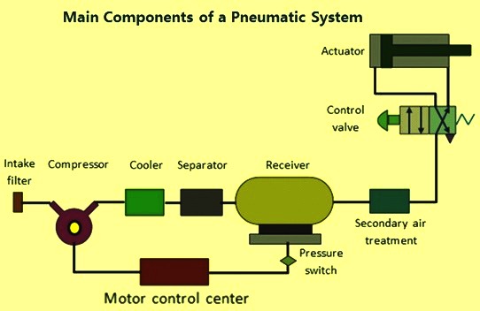
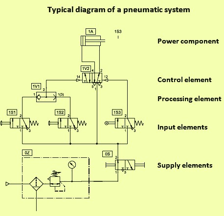
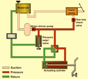
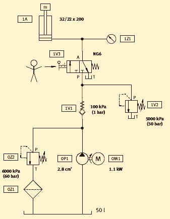

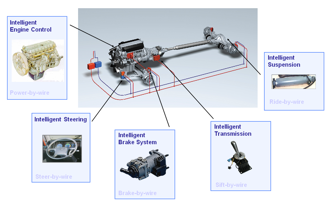
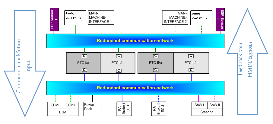
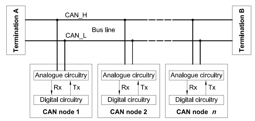
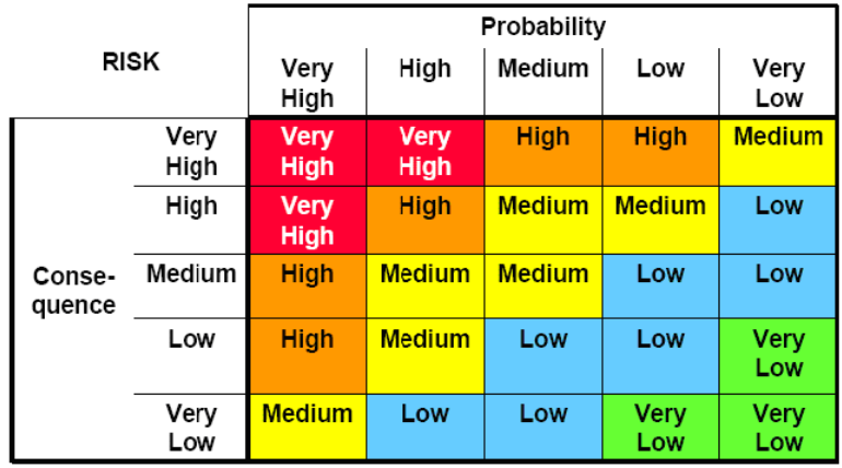
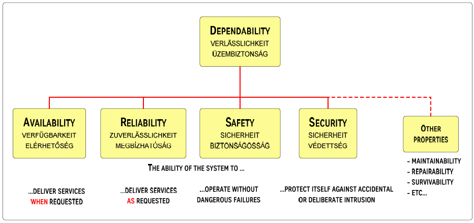
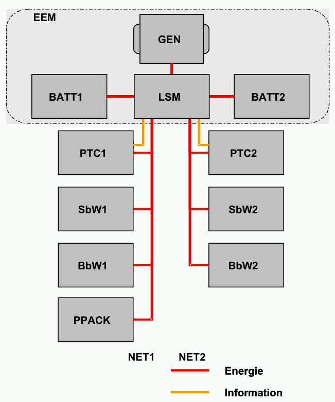
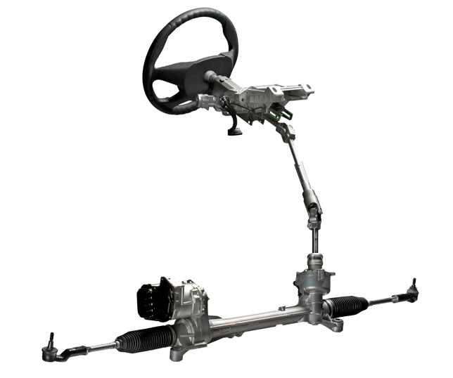
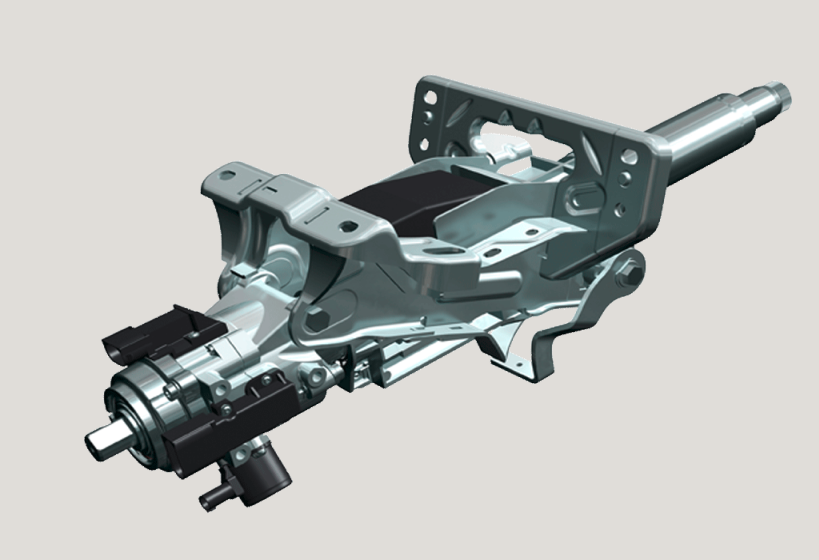
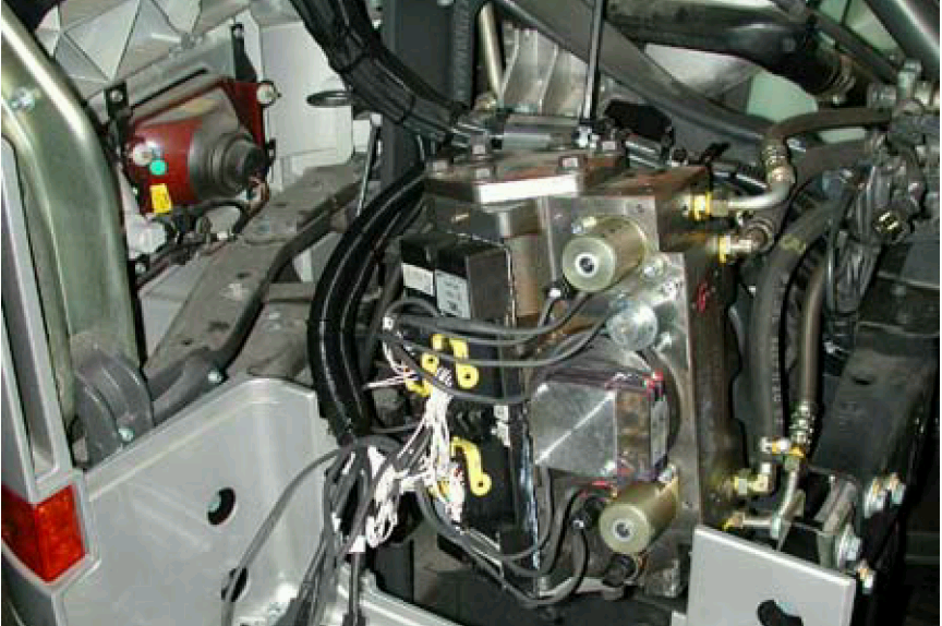
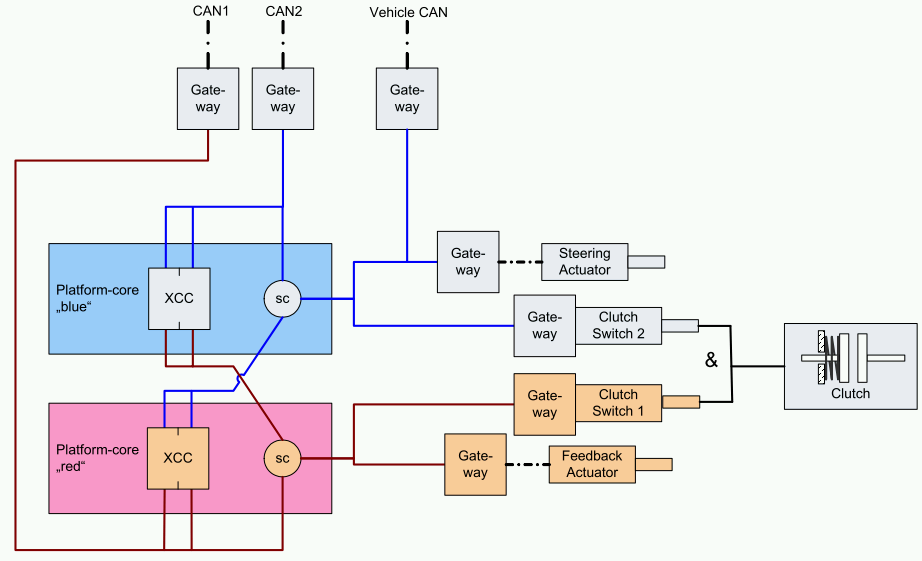
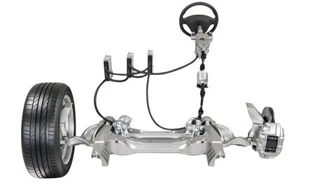
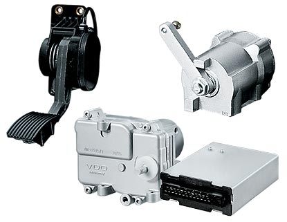
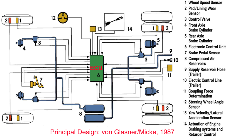
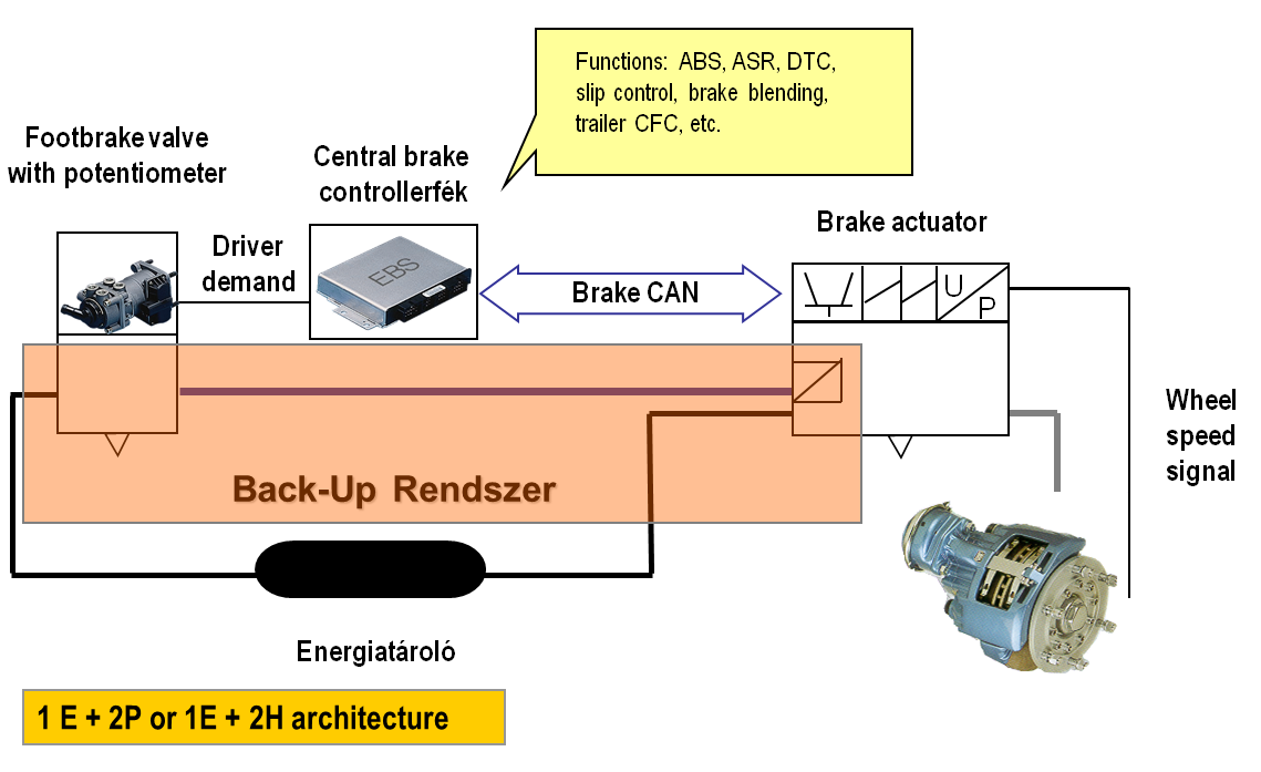
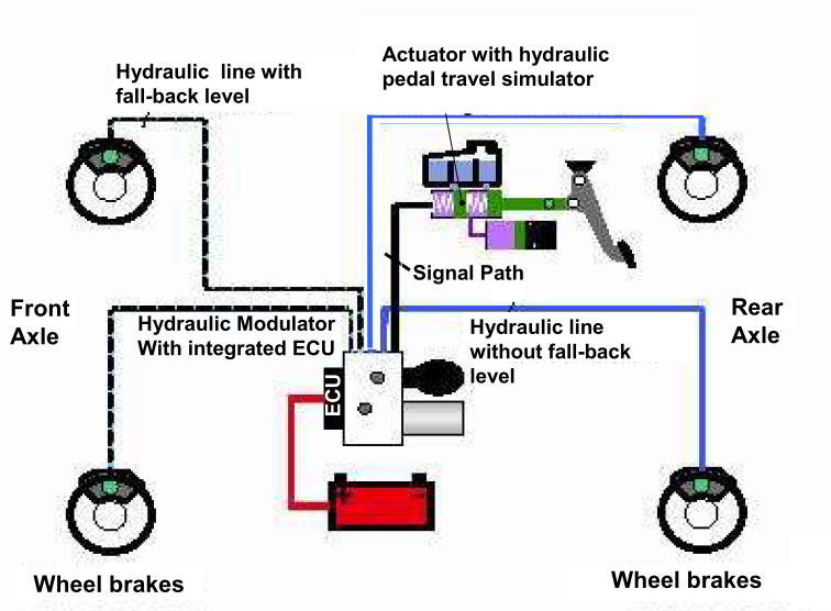
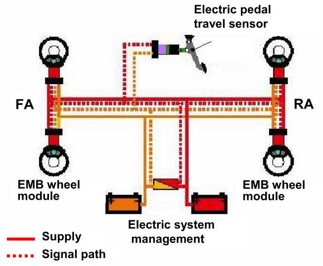
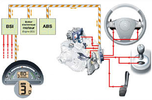
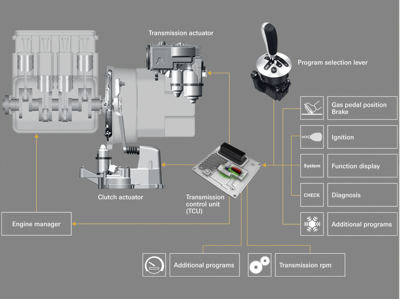
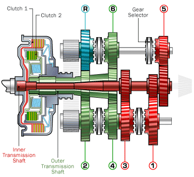
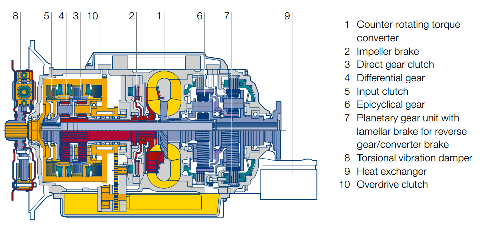
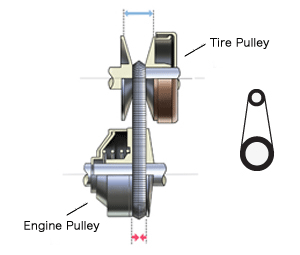
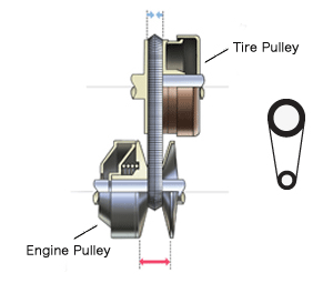


 In the case of the Sidewinder air-to-air missile, one of two available guidance control sections is utilized in conjunction with one of two discrete fuses.


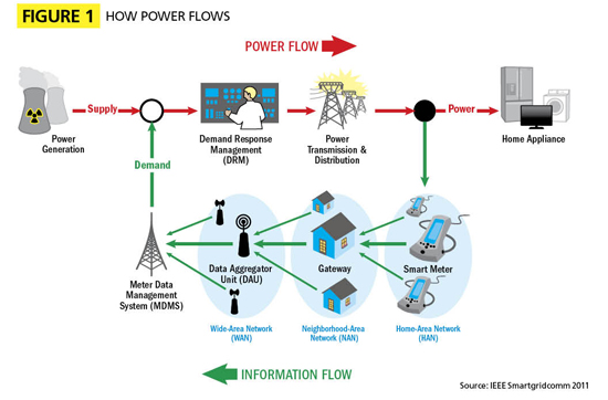
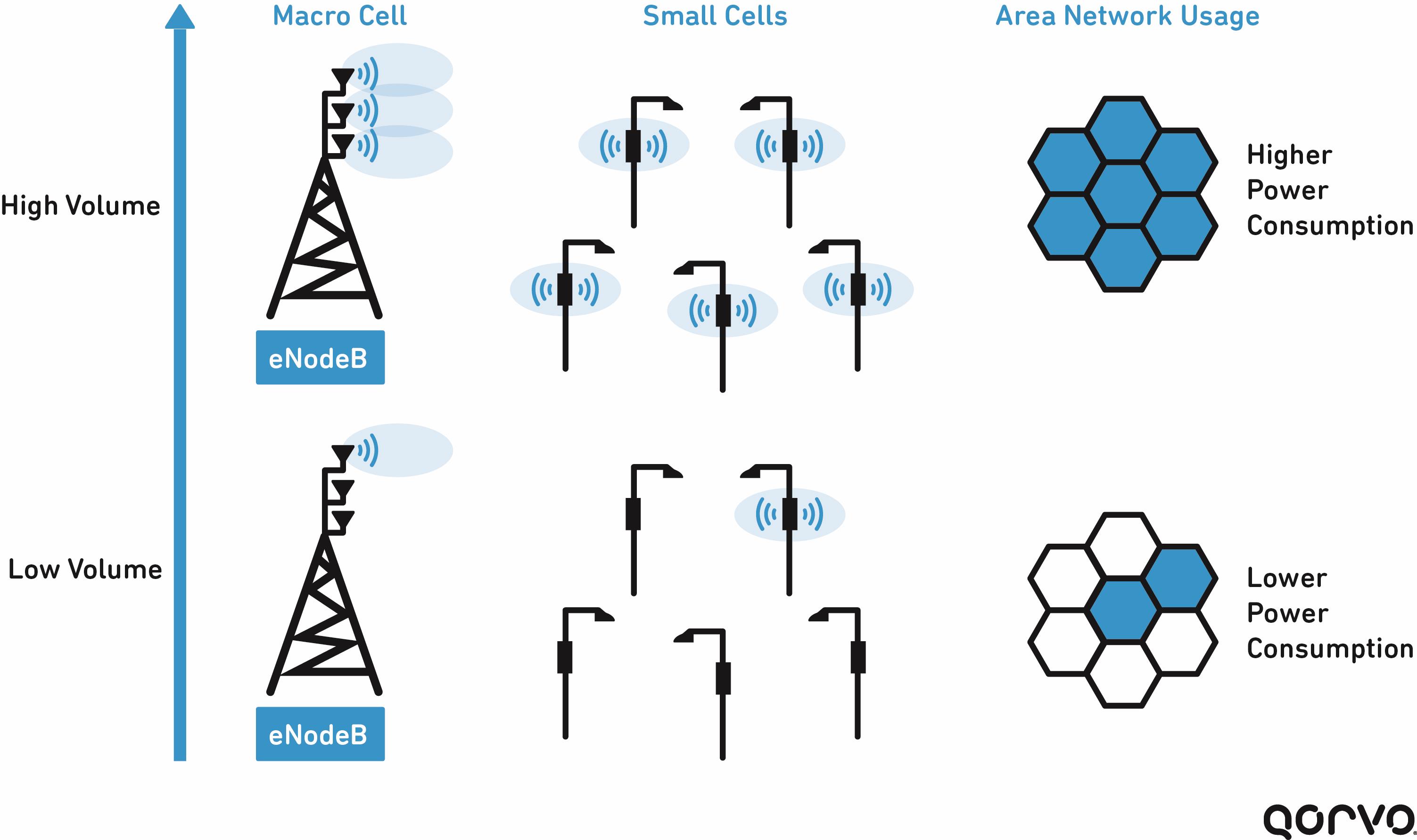
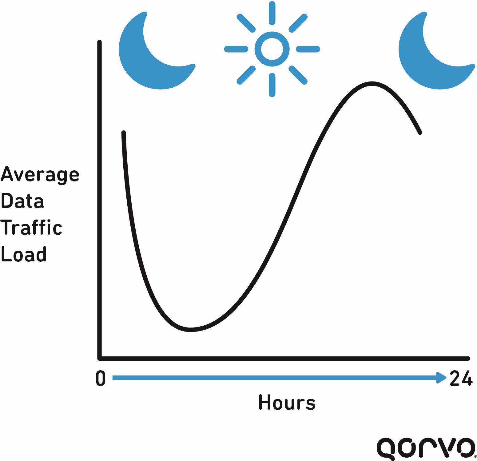 Base stations have been designed to address peak capacities, minimizing downtime and optimizing user experience. But in reality, networks that are energy efficient at heavy load conditions are far less efficient-per-bit at lower load conditions. As it turns out, it is very common during any given 24-hour period for a cellular network’s load to be low, rather than at its peak – daily load levels are very uneven.
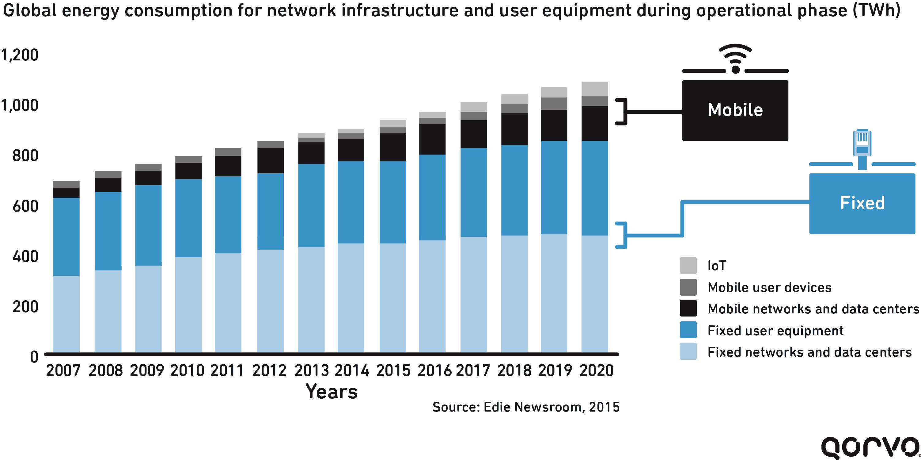
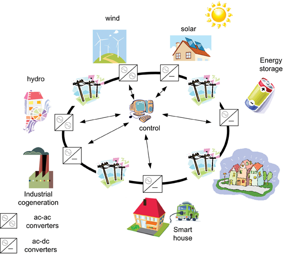


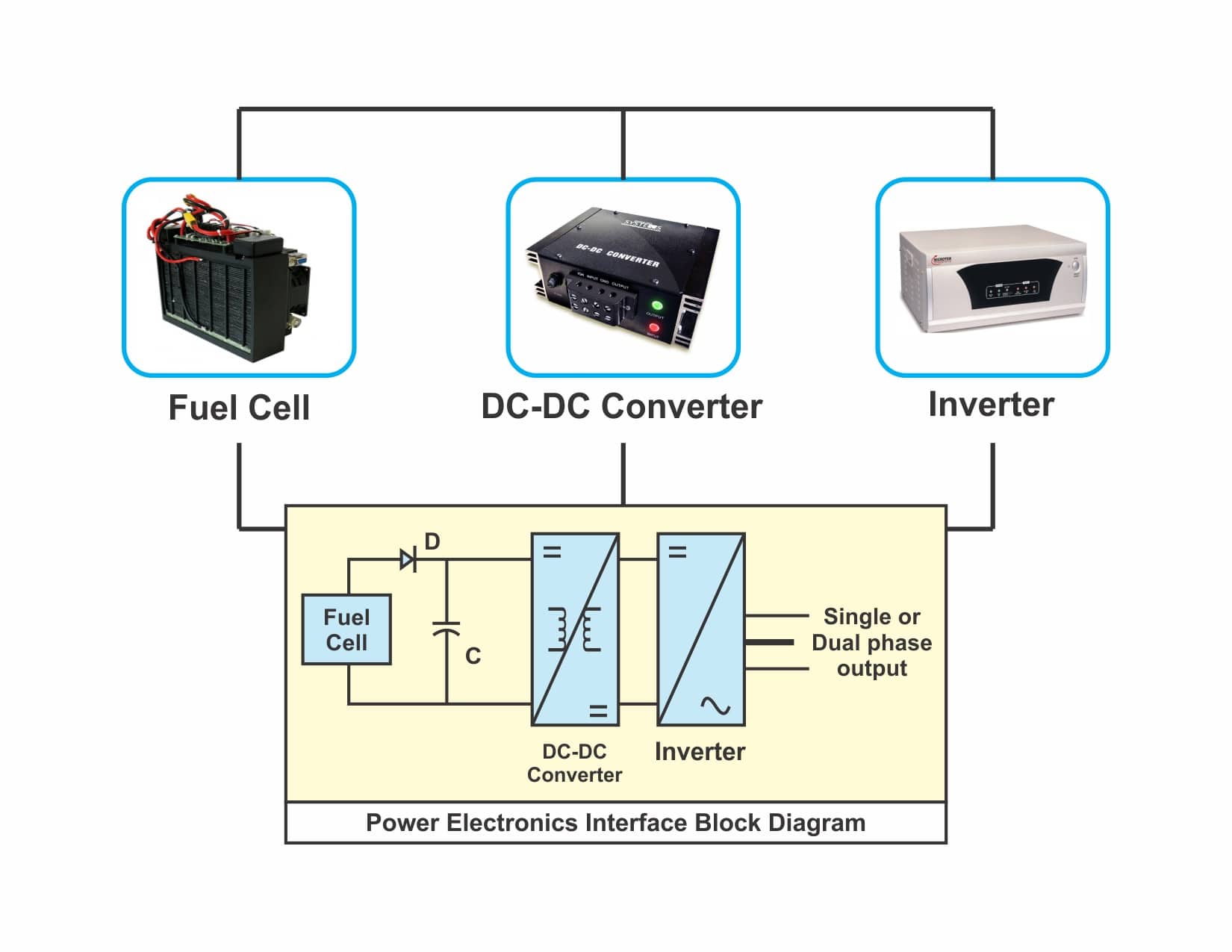
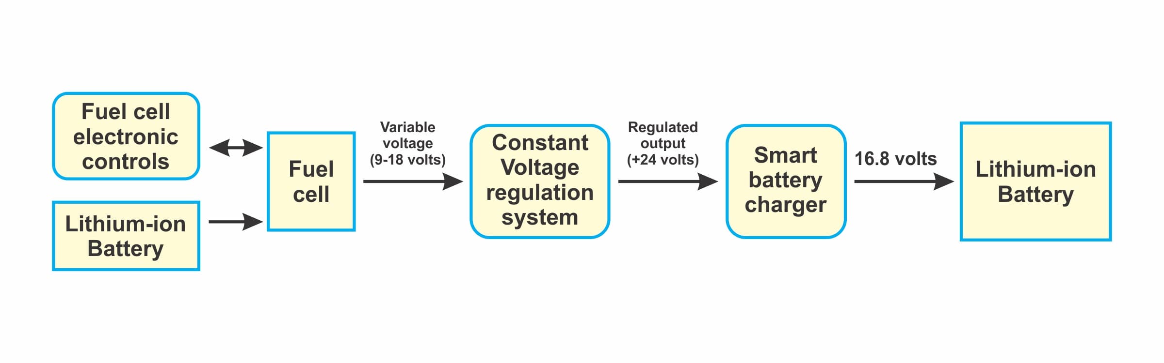


Tidak ada komentar:
Posting Komentar