equality of automotive components with electronic components :
the progress of the electronic component industry has penetrated into the automotive industry has been very necessary because the energy used is quite widely available from petroleum energy, in fact all component components in automatic systems can be replaced by independent electronic component components only need to study and discover component material electronic adjustment so that it can be conditioned on automotive components so that it has strong power for the needs of motion and conditions for long distances for vehicles .
the function & significance of the component electronic compare to automotive component :
- Capacitor in automotive ; we call condenser
- Resistor in automotive ; we call Load as like lamp , switch .
- Diode In automotive ; we call rectifier it was in dynamo starter
- Transistor In automotive ; we call regulator and amplification signal
- Inductor In automotive ; We call Coil
- Relay In automotive ; We call platinum and spark plugs
- Quartz Crystal In automotive ; We call alternator
LOVE & LIGHTING
Gen . Mac Tech Zone e- Transformation Component
Internal combustion engine
_________________________________________________________________________________
An internal combustion engine (ICE) is a heat engine where the combustion of a fuel occurs with an oxidizer (usually air) in a combustion chamber that is an integral part of the working fluid flow circuit. In an internal combustion engine, the expansion of the high-temperature and high-pressure gases produced by combustion applies direct force to some component of the engine. The force is applied typically to pistons, turbine blades, rotor or a nozzle. This force moves the component over a distance, transforming chemical energy into useful mechanical energy.
The first commercially successful internal combustion engine was created by Étienne Lenoir around 1859[1] and the first modern internal combustion engine was created in 1876 by Nikolaus Otto (see Otto engine).
The term internal combustion engine usually refers to an engine in which combustion is intermittent, such as the more familiar four-stroke and two-stroke piston engines, along with variants, such as the six-stroke piston engine and the Wankel rotary engine. A second class of internal combustion engines use continuous combustion: gas turbines, jet engines and most rocket engines, each of which are internal combustion engines on the same principle as previously described.Firearms are also a form of internal combustion engine.[2]
In contrast, in external combustion engines, such as steam or Stirling engines, energy is delivered to a working fluid not consisting of, mixed with, or contaminated by combustion products. Working fluids can be air, hot water, pressurized water or even liquid sodium, heated in a boiler. ICEs are usually powered by energy-dense fuels such as gasoline or diesel fuel, liquids derived from fossil fuels. While there are many stationary applications, most ICEs are used in mobile applications and are the dominant power supply for vehicles such as cars, aircraft, and boats.
Typically an ICE is fed with fossil fuels like natural gas or petroleum products such as gasoline, diesel fuel or fuel oil. There is a growing usage of renewable fuels like biodiesel for CI (compression ignition) engines and bioethanol or methanol for SI (spark ignition) engines. Hydrogen is sometimes used, and can be obtained from either fossil fuels or renewable energy.

Diagram of a cylinder as found in 4-stroke gasoline engines.:
C – crankshaft.
E – exhaust camshaft.
I – inlet camshaft.
P – piston.
R – connecting rod.
S – spark plug.
V – valves. red: exhaust, blue: intake.
W – cooling water jacket.
gray structure – engine block
Applications
_______________________________________________________
Reciprocating piston engines are by far the most common power source for land and water vehicles, including automobiles, motorcycles, ships and to a lesser extent, locomotives (some are electrical but most use Diesel engines). Rotary engines of the Wankel design are used in some automobiles, aircraft and motorcycles.

Where high power-to-weight ratios are required, internal combustion engines appear in the form of combustion turbines or Wankel engines. Powered aircraft typically uses an ICE which may be a reciprocating engine. Airplanes can instead use jet engines and helicopters can instead employ turboshafts; both of which are types of turbines. In addition to providing propulsion, airliners may employ a separate ICE as an auxiliary power unit. Wankel engines are fitted to many unmanned aerial vehicles.
ICEs drive some of the large electric generators that power electrical grids. They are found in the form of combustion turbines in combined cycle power plants with a typical electrical output in the range of 100 MW to 1 GW. The high temperature exhaust is used to boil and superheat water to run a steam turbine. Thus, the efficiency is higher because more energy is extracted from the fuel than what could be extracted by the combustion turbine alone. In combined cycle power plants efficiencies in the range of 50% to 60% are typical. In a smaller scale Diesel generators are used for backup power and for providing electrical power to areas not connected to an electric grid.

Small engines (usually 2‐stroke gasoline engines) are a common power source for lawnmowers, string trimmers, chain saws, leafblowers, pressure washers, snowmobiles, jet skis, outboard motors, mopeds, and motorcycles.
Classification
There are several possible ways to classify internal combustion engines.Reciprocating
- By number of strokes
- Two-stroke engine
- Clerk cycle
- Day cycle
- Four-stroke engine (Otto cycle)
- Six-stroke engine
- Two-stroke engine
- By type of ignition
- Compression-ignition engine
- Spark-ignition engine (commonly found as gasoline engines)
- By mechanical/thermodynamical cycle (these 2 cycles do not encompass all reciprocating engines, and are infrequently used):
Rotary
Continuous combustion
Reciprocating engines
Structure
The base of a reciprocating internal combustion engine is the engine block, which is typically made of cast iron or aluminium. The engine block contains the cylinders. In engines with more than one cylinder they are usually arranged either in 1 row (straight engine) or 2 rows (boxer engine or V engine); 3 rows are occasionally used (W engine) in contemporary engines, and other engine configurations are possible and have been used. Single cylinder engines are common for motorcycles and in small engines of machinery. Water-cooled engines contain passages in the engine block where cooling fluid circulates (the water jacket). Some small engines are air-cooled, and instead of having a water jacket the cylinder block has fins protruding away from it to cool by directly transferring heat to the air. The cylinder walls are usually finished by honing to obtain a cross hatch, which is better able to retain the oil. A too rough surface would quickly harm the engine by excessive wear on the piston.

The pistons are short cylindrical parts which seal one end of the cylinder from the high pressure of the compressed air and combustion products and slide continuously within it while the engine is in operation. The top wall of the piston is termed its crown and is typically flat or concave. Some two-stroke engines use pistons with a deflector head. Pistons are open at the bottom and hollow except for an integral reinforcement structure (the piston web). When an engine is working the gas pressure in the combustion chamber exerts a force on the piston crown which is transferred through its web to a gudgeon pin. Each piston has rings fitted around its circumference that mostly prevent the gases from leaking into the crankcase or the oil into the combustion chamber. A ventilation system drives the small amount of gas that escape past the pistons during normal operation (the blow-by gases) out of the crankcase so that it does not accumulate contaminating the oil and creating corrosion. In two-stroke gasoline engines the crankcase is part of the air–fuel path and due to the continuous flow of it they do not need a separate crankcase ventilation system.
The cylinder head is attached to the engine block by numerous bolts or studs. It has several functions. The cylinder head seals the cylinders on the side opposite to the pistons; it contains short ducts (the ports) for intake and exhaust and the associated intake valves that open to let the cylinder be filled with fresh air and exhaust valves that open to allow the combustion gases to escape. However, 2-stroke crankcase scavenged engines connect the gas ports directly to the cylinder wall without poppet valves; the piston controls their opening and occlusion instead. The cylinder head also holds the spark plug in the case of spark ignition engines and the injector for engines that use direct injection. All CI engines use fuel injection, usually direct injection but some engines instead use indirect injection. SI engines can use a carburetor or fuel injection as port injection or direct injection. Most SI engines have a single spark plug per cylinder but some have 2. A head gasket prevents the gas from leaking between the cylinder head and the engine block. The opening and closing of the valves is controlled by one or several camshafts and springs—or in some engines—a desmodromic mechanism that uses no springs. The camshaft may press directly the stem of the valve or may act upon a rocker arm, again, either directly or through a pushrod.


The cylinder head has an intake manifold and an exhaust manifold attached to the corresponding ports. The intake manifold connects to the air filter directly, or to a carburetor when one is present, which is then connected to the air filter. It distributes the air incoming from these devices to the individual cylinders. The exhaust manifold is the first component in the exhaust system. It collects the exhaust gases from the cylinders and drives it to the following component in the path. The exhaust system of an ICE may also include a catalytic converter and muffler. The final section in the path of the exhaust gases is the tailpipe.
4-stroke engines

- Intake, induction or suction: The intake valves are open as a result of the cam lobe pressing down on the valve stem. The piston moves downward increasing the volume of the combustion chamber and allowing air to enter in the case of a CI engine or an air fuel mix in the case of SI engines that do not use direct injection. The air or air-fuel mixture is called the charge in any case.
- Compression: In this stroke, both valves are closed and the piston moves upward reducing the combustion chamber volume which reaches its minimum when the piston is at TDC. The piston performs work on the charge as it is being compressed; as a result its pressure, temperature and density increase; an approximation to this behavior is provided by the ideal gas law. Just before the piston reaches TDC, ignition begins. In the case of a SI engine, the spark plug receives a high voltage pulse that generates the spark which gives it its name and ignites the charge. In the case of a CI engine the fuel injector quickly injects fuel into the combustion chamber as a spray; the fuel ignites due to the high temperature.
- Power or working stroke: The pressure of the combustion gases pushes the piston downward, generating more work than it required to compress the charge. Complementary to the compression stroke, the combustion gases expand and as a result their temperature, pressure and density decreases. When the piston is near to BDC the exhaust valve opens. The combustion gases expand irreversibly due to the leftover pressure—in excess of back pressure, the gauge pressure on the exhaust port—; this is called the blowdown.
- Exhaust: The exhaust valve remains open while the piston moves upward expelling the combustion gases. For naturally aspirated engines a small part of the combustion gases may remain in the cylinder during normal operation because the piston does not close the combustion chamber completely; these gases dissolve in the next charge. At the end of this stroke, the exhaust valve closes, the intake valve opens, and the sequence repeats in the next cycle. The intake valve may open before the exhaust valve closes to allow better scavenging.
2-stroke engines
2-stroke engine
The defining characteristic of this kind of engine is that each piston completes a cycle every crankshaft revolution. The 4 processes of intake, compression, power and exhaust take place in only 2 strokes so that it is not possible to dedicate a stroke exclusively for each of them. Starting at TDC the cycle consist of:- Power: While the piston is descending the combustion gases perform work on it, as in a 4-stroke engine. The same thermodynamic considerations about the expansion apply.
- Scavenging: Around 75° of crankshaft rotation before BDC the exhaust valve or port opens, and blowdown occurs. Shortly thereafter the intake valve or transfer port opens. The incoming charge displaces the remaining combustion gases to the exhaust system and a part of the charge may enter the exhaust system as well. The piston reaches BDC and reverses direction. After the piston has traveled a short distance upwards into the cylinder the exhaust valve or port closes; shortly the intake valve or transfer port closes as well.
- Compression: With both intake and exhaust closed the piston continues moving upwards compressing the charge and performing a work on it. As in the case of a 4-stroke engine, ignition starts just before the piston reaches TDC and the same consideration on the thermodynamics of the compression on the charge.
Crankcase scavenged
Some SI engines are crankcase scavenged and do not use poppet valves. Instead the crankcase and the part of the cylinder below the piston is used as a pump. The intake port is connected to the crankcase through a reed valve or a rotary disk valve driven by the engine. For each cylinder a transfer port connects in one end to the crankcase and in the other end to the cylinder wall. The exhaust port is connected directly to the cylinder wall. The transfer and exhaust port are opened and closed by the piston. The reed valve opens when the crankcase pressure is slightly below intake pressure, to let it be filled with a new charge; this happens when the piston is moving upwards. When the piston is moving downwards the pressure in the crankcase increases and the reed valve closes promptly, then the charge in the crankcase is compressed. When the piston is moving upwards, it uncovers the exhaust port and the transfer port and the higher pressure of the charge in the crankcase makes it enter the cylinder through the transfer port, blowing the exhaust gases. Lubrication is accomplished by adding 2-stroke oil to the fuel in small ratios. Petroil refers to the mix of gasoline with the aforesaid oil. This kind of 2-stroke engines has a lower efficiency than comparable 4-strokes engines and release a more polluting exhaust gases for the following conditions:
- They use a total-loss lubrication system: all the lubricating oil is eventually burned along with the fuel.
- There are conflicting requirements for scavenging: On one side, enough fresh charge needs to be introduced in each cycle to displace almost all the combustion gases but introducing too much of it means that a part of it gets in the exhaust.
- They must use the transfer port(s) as a carefully designed and placed nozzle so that a gas current is created in a way that it sweeps the whole cylinder before reaching the exhaust port so as to expel the combustion gases, but minimize the amount of charge exhausted. 4-stroke engines have the benefit of forcibly expelling almost all of the combustion gases because during exhaust the combustion chamber is reduced to its minimum volume. In crankcase scavenged 2-stroke engines, exhaust and intake are performed mostly simultaneously and with the combustion chamber at its maximum volume.
In the US, 2-stroke engines were banned for road vehicles due to the pollution. Off-road only motorcycles are still often 2-stroke but are rarely road legal. However, many thousands of 2-stroke lawn maintenance engines are in use.
Blower scavenged
Using a separate blower avoids many of the shortcomings of crankcase scavenging, at the expense of increased complexity which means a higher cost and an increase in maintenance requirement. An engine of this type uses ports or valves for intake and valves for exhaust, except opposed piston engines, which may also use ports for exhaust. The blower is usually of the Roots-type but other types have been used too. This design is commonplace in CI engines, and has been occasionally used in SI engines.
CI engines that use a blower typically use uniflow scavenging. In this design the cylinder wall contains several intake ports placed uniformly spaced along the circumference just above the position that the piston crown reaches when at BDC. An exhaust valve or several like that of 4-stroke engines is used. The final part of the intake manifold is an air sleeve which feeds the intake ports. The intake ports are placed at an horizontal angle to the cylinder wall (I.e: they are in plane of the piston crown) to give a swirl to the incoming charge to improve combustion. The largest reciprocating IC are low speed CI engines of this type; they are used for marine propulsion (see marine diesel engine) or electric power generation and achieve the highest thermal efficiencies among internal combustion engines of any kind. Some Diesel-electric locomotive engines operate on the 2-stroke cycle. The most powerful of them have a brake power of around 4.5 MW or 6,000 HP. The EMD SD90MAC class of locomotives use a 2-stroke engine. The comparable class GE AC6000CW whose prime mover has almost the same brake power uses a 4-stroke engine.
An example of this type of engine is the Wärtsilä-Sulzer RTA96-C turbocharged 2-stroke Diesel, used in large container ships. It is the most efficient and powerful reciprocating internal combustion engine in the world with a thermal efficiency over 50%. For comparison, the most efficient small four-stroke engines are around 43% thermally-efficient (SAE 900648); size is an advantage for efficiency due to the increase in the ratio of volume to surface area.
Fuels and oxidizers
All internal combustion engines depend on combustion of a chemical fuel, typically with oxygen from the air (though it is possible to inject nitrous oxide to do more of the same thing and gain a power boost). The combustion process typically results in the production of a great quantity of heat, as well as the production of steam and carbon dioxide and other chemicals at very high temperature; the temperature reached is determined by the chemical make up of the fuel and oxidisers (see stoichiometry), as well as by the compression and other factors.Fuels
The most common modern fuels are made up of hydrocarbons and are derived mostly from fossil fuels (petroleum). Fossil fuels include diesel fuel, gasoline and petroleum gas, and the rarer use of propane. Except for the fuel delivery components, most internal combustion engines that are designed for gasoline use can run on natural gas or liquefied petroleum gases without major modifications. Large diesels can run with air mixed with gases and a pilot diesel fuel ignition injection. Liquid and gaseous biofuels, such as ethanol and biodiesel (a form of diesel fuel that is produced from crops that yield triglycerides such as soybean oil), can also be used. Engines with appropriate modifications can also run on hydrogen gas, wood gas, or charcoal gas, as well as from so-called producer gas made from other convenient biomass. Experiments have also been conducted using powdered solid fuels, such as the magnesium injection cycle.Presently, fuels used include:
- Petroleum:
- Petroleum spirit (North American term: gasoline, British term: petrol)
- Petroleum diesel.
- Autogas (liquified petroleum gas).
- Compressed natural gas.
- Jet fuel (aviation fuel)
- Residual fuel
- Coal:
- Gasoline can be made from carbon (coal) using the Fischer-Tropsch process
- Diesel fuel can be made from carbon using the Fischer-Tropsch process
- Biofuels and vegetable oils:
- Peanut oil and other vegetable oils.
- Woodgas, from an onboard wood gasifier using solid wood as a fuel
- Biofuels:
- Biobutanol (replaces gasoline).
- Biodiesel (replaces petrodiesel).
- Dimethyl Ether (replaces petrodiesel).
- Bioethanol and Biomethanol (wood alcohol) and other biofuels (see Flexible-fuel vehicle).
- Biogas
- Hydrogen (mainly spacecraft rocket engines)
Starting
Starter motor
Internal combustion engines must have their cycles started. In reciprocating engines this is accomplished by turning the crankshaft (Wankel Rotor Shaft) which induces the cycles of intake, compression, combustion, and exhaust. The first engines were started with a turn of their flywheels, while the first vehicle (the Daimler Reitwagen) was started with a hand crank. All ICE engined automobiles were started with hand cranks until Charles Kettering developed the electric starter for automobiles. This method is now the most widely used, even among non-automobiles.
As diesel engines have become larger and their mechanisms heavier, air starters have come into use. This is due to the lack of torque in electric starters. Air starters work by pumping compressed air into the cylinders of an engine to start it turning.
Two-wheeled vehicles may have their engines started in one of four ways:
- By pedaling, as on a bicycle
- By pushing the vehicle and then engaging the clutch, known as "run-and-bump starting"
- By kicking downward on a single pedal, known as "kick starting"
- By an electric starter, as in cars
Some small engines use a pull-rope mechanism called "recoil starting," as the rope rewinds itself after it has been pulled out to start the engine. This method is commonly used in pushed lawn mowers and other settings where only a small amount of torque is needed to turn an engine over.
Turbine engines are frequently started by an electric motor or by compressed air.
Energy and Chemical Stability
_________________________________________________________
Natural systems left to themselves move towards states of lower potential energy. For example, water flows down a hill or a ball rolls down a hill, if free to do so. States of lower potential energy are more stable. As a rule, the lower the potential energy of a system, the more stable it is. As a result, left to themselves, systems attempt to reach the configuration with the lowest energy possible under a given set of constraints. To change the state of a system from lower to higher potential energy, one must therefore supply energy to the system.
less stable
| more stable | |
higher potential energy
| lower potential energy | |
less bound
| more bound |
Chemical Stability
Chemicals and their reactions are the medium through which nature stores and transforms energy. This energy is partly derived from the sun's pure electromagnetic energy that reaches the Earth as solar radiation, and partly from the energy stored in chemicals as potential energy in the chemical bonds. Recall the food chain diagram from the Introduction. Photosynthesis is an example of how nature stores and transforms energy via chemical bonds. Chemical bonds are essentially the phenomenon that atoms of elements stay close to each other, forming a compound, because that puts them in a lower (more stable) state of total energy.
These lower energy configurations of elements happen when the elements get an electronic configuration similar to the nearest inert gas. Electronic configurations of inert (noble) gases are the most stable in a given period (horizontal segment) of the Periodic Table. In fact, that is why these specific elements do not "need" to react with anything and are, therefore, chemically inert (or "noble"). These elements have no "need" to combine because their electron shells are completely filled with electrons. The noble gases are helium (He), neon (Ne), argon (Ar), krypton (Kr), xenon (Xe), and radon (Rn). Chemical activities of the elements are simplest to predict when they are close to the inert gases in the periodic table.
When similar atoms such as H or O or N come together they can gain stability by sharing electrons in a covalent bond. Shared electrons spend time with either of the H atoms in H2 for equal amounts of time, for instance. In a case of a covalent bond such as those in H2O, however, the electrons spend more time on the average in the neighborhood of the oxygen.
The water molecule, which has an angle of 105° between the two H-O bonds, is therefore a polar molecule, being more negative at the oxygen end of the molecule, because the negatively charged electrons spend more time near the oxygen atom.
Nitrogen, hydrogen and oxygen atoms go to more stable configurations by forming the diatomic gases, N2, H2, and O2 respectively rather than remain in the atomic form: N, H, and O. When hydrogen atoms are produced in any reaction, pairs of these hydrogen atoms form covalent bonds with each other so that each has the helium (nearest inert gas) configuration at least a fraction of the time. Hydrogen has one electron and needs a total of two to be like He. So two hydrogen atoms share a pair of electrons, each belonging to one of the original atoms, thus forming H2. Schematically, it could be written as HxxH (x representing an electron). This schema is represented by H-H where the single line represents a bond consisting of two shared electrons.
Again, the same can be said for oxygen and nitrogen. Oxygen has an atomic number of 8, and has four electrons in the outermost shell. It needs two more to be like neon (nearest inert gas).
| Exercise: |
| Nitrogen has __ electrons in the outer shell, needs __ to be more like ___ Carbon has __ electrons in the outer shell, needs __ to be more like ____ Oxygen has __ electrons in the outer shell, needs __ to be more like ____ Phosphorus has __ electrons in the outer shell, needs __ to be more like __ Hydrogen has __ electron in the outer shell, needs __ to be more like _____ answers |
Figure 14: Bond configurations for
carbon, nitrogen, oxygen, phosphorus, and hydrogen. |
Representation of Bonds
Each atom has a number of bonds coming out of it equal to the number of electrons it shares in covalent bonds. So the line of a bond represents two electrons in activity, one from each of the two atoms it bonds. Thus for H2, H-H is really H:H, with each hydrogen atom contributing one electron to the bond.
Let's look at the example of nitrogen (atomic number = 7). Nitrogen, being 3 electrons short of its nearest inert gas (neon, atomic no. = 10), tries to bond so as to share 3 of it's electrons with other atoms bonding with it, in order to get a complete shell of 10 whenever possible. Thus it may share electrons with another N atom (forming N2), or with hydrogen (forming NH3).
Carbon is the basis for all our life forms. It is a very versatile atom because of its capability to form four bonds. Depending on the amount of hydrogen available to bond, and the temperature and pressure conditions, carbon can form a plethora of compounds with hydrogen alone. One such family is the hydrocarbons, important in our context because they are the basis of fossil fuels.
Note how some of these compounds have double and triple bonds between carbons. This happens when carbon and hydrogen combine under circumstances in which there is not enough hydrogen to satisfy all four bonds of each carbon. For example, if there is plenty of hydrogen to combine with carbon, we get CH4 or C2H6 (Ethane), with all single bonds. With less hydrogen we get C2H4 or C2H2 (less hydrogen for the same number of C atoms). C2H4 has a double bond between the carbons, and C2H2 has a triple bond. Compounds with double and triple bonds are called unsaturated, while single bond compounds like C2H6 are said to be saturated. Unsaturated compounds are more reactive than saturated compounds because not all the C atoms are bonded to four other atoms. Hydrocarbons are not the only compounds that can be unsaturated. Carbon monoxide is a good example of an unsaturated compound, "looking" for another oxygen atom to form CO2, a more saturated compound. When carbon (in coal or wood, for example) burns in an environment with insufficient oxygen, it forms CO which is deadly when breathed in. This is the reason to ensure plenty of access to fresh air when we have a fireplace or running car engine.
Note that many representations are two-dimensional, and that in actuality, the electrons forming the bonds are distributed in three dimensions. In a compound like CH4, the carbon is in the middle of a tetrahedron with the 4 H atoms at the vectors.
Try drawing propane, butane, and pentane. Note that there are always four bonds coming from carbon. The linear structures are called aliphatic hydrocarbons. In addition to the linear hydrocarbon molecules, hydrocarbons may also be formed into ring structures. The ring structure possesses the property that enables us to smell these compounds! So they are called aromatic hydrocarbons. The simplest aromatic hydrocarbon is C6H6, benzene. The structure of benzene was long a puzzle in chemistry, with chemists wondering what the structural formula for C6H6 could be. They knew the empirical formula was C6H6. It is said that the great organic chemist Kekulé, who had been wondering about this, dreamed one night of a snake swallowing its tail and was inspired to draw the ring structure! Note the alternating single and double bonds, a clever way of ensuring four bonds from each carbon shell.
The versatility of carbon in forming bonds, ring structures and various configurations is the basis of life on our planet. The chemistry of carbon compounds is therefore called organic chemistry. More complicated carbons compounds are described in the Ecological System and Materials System. For now, let us look at some additional aromatic and aliphatic compounds, and note some aspects that are relevant to energy storage and release.
Aliphatic hydrocarbons are the basis of fossil fuels. All saturated hydrocarbons react with oxygen at high temperatures to form carbon dioxide and water, and give off energy. This oxidation reaction is the basis of the internal combustion engine. Gasoline normally contains hydrocarbons from C6 to C18, a mixture of over 100 compounds! An example reaction of the combustion of a hydrocarbon is:
C7H16 + 11O2  7CO2 + 8H2O + energy
"Burning" (or a combustion reaction) consists of combining with oxygen at high temperatures. The combustion reaction of acetylene (C2H2) with oxygen gives off such a large amount of energy that it is used as a welder's torch.Ring compounds do not play as large a role in energy production but often occur as byproducts or waste products. These polyaromatic hydrocarbons (PAH's) pose a serious pollution problem.
Ring compounds, based on the benzene ring, are so common in biochemistry that we just draw
Ring compounds can get very complicated. Several organic compounds playing an important role in our physiology are shown in the Ecological System.
Chemical Energy Release and Bond Energies
The amount of energy released when a bond is formed between atoms is called the bond energy. Bond energies represent a state of potential chemical energy. We can get energy from a system as it moves from a state of higher potential energy to one of lower potential energy (e.g. water falling). Chemical reactions in which the compounds formed after a reaction (called products) have lower total bond energy than the reactants can release chemical energy. Such reactions in which energy is given off are called exothermic (or more correctly, exoergic) reactions. Conversely, reactions that absorb energy are said to be endothermic.
Table 8 gives the energies for bonds we will commonly encounter. The table defines these energies in units of kcal/mole. A mole
|
| |||||||||||||||||||||||||||||||||||||||||||||
Table 8: Bond Energies.
(the bond energy is expressed in kcal/mole.) | ||||||||||||||||||||||||||||||||||||||||||||||
Science Notes: Chemical Formations
Formation of Ammonia (NH3) as Example
Let us look at a more complicated example of the formation of a molecule. Just as the energy released by water falling can be captured, we can find ways to capture chemical energy. Let us look at a more complicated reaction: the formation of ammonia. Nitrogen gas (N2) and hydrogen gas (H2) can be made to combine to form NH3, or ammonia gas. As we proceed, look for the answers to these questions: Is the reaction exothermic? How many kilograms of hydrogen are needed to produce one kilogram of ammonia?
The reaction is N2 + 3H2 2NH3
This equation says that one mole of N2 requires three moles of H2 for a complete reaction, and this would then yield two moles of NH3. Note that we can also say that one molecule of N2 reacts with three molecules of H2 to yield two molecules of ammonia (NH3). But the table gives energies in units of kcal/mole, which is why it is easier to work with moles. The energy involved in the reaction involving just one or two molecules of ammonia is too small.The following table contains the variety of ways in which you can write the reaction that forms ammonia. All the descriptions below are equivalent. The atomic masses are rounded off values from the Periodic Table.
Nitrogen
|
+
|
Hydrogen
|
Ammonia
| ||
N2
|
+
|
3H2
|
2NH3
| ||
+
|
3 H-H
|
2NH3
| |||
1 mole of N2
|
+
|
3 moles of H2
|
2 moles of ammonia
| ||
28 g of N
|
+
|
6 g of H
|
34 g ammonia
| ||
N
|
225 kcal/mole
|
H - H
|
104 kcal/mole
|
N - H
|
94 kcal/mole
|
Energy required to break
the bonds of N2, 3H2 |
Energy released forming
the bond 2NH3 | |||||||||
N2
|
:
|
1 mole x 225 kcal/mole
|
=
|
225
|
2NH3
|
:
|
2 moles x (3 x 93 kcal/mole) =
2 moles x 279 kcal/mole =
|
558
| ||
3H2
|
:
|
3 moles x 104 kcal/mole
|
=
|
312
|
total energy released
|
=
| 558 kcal | |||
total energy absorbed
|
=
|
537 kcal
| ||||||||
558 kcal - 537 kcal = 21 net kcal released for 2 moles of NH2 formed, so the net energy released is 10.5 kcal/mole of ammonia formed.
| ||||||||||
For this reaction, we had to put in some energy to "activate" the reaction, which was the energy required to break the N2 and H2 bonds. N2 and H2 brought together with no addition of energy would not spontaneously react. This is analogous to our striking a match to start the burning of coal. The energy required to start the reaction is called activation energy. Then, left to themselves, the N and H form bonds to release 568 calories.
What is a corresponding example with the gravitational force?Formation of Water (H2O) as Example
Hydrogen and oxygen combine to form water. Which is more stable -- hydrogen and oxygen gas separately, or in combination as water?
Write equation and balance:
2H2 + O2 2H2O
| amounts | element | element | compound | ||
| molecules |
2 molecules hydrogen
|
+
|
1 molecule
oxygen |
2 molecules water
| |
| moles |
2 moles hydrogen
|
+
|
1 mole
oxygen |
2 moles of water
| |
| grams |
4 g hydrogen
|
+
|
32 g oxygen
|
36g water
| |
| kilograms |
4kg H2
|
+
|
32 kg O2
|
36 kg water
| |
| 1. Is the reaction exothermic or endothermic? 2. Which is more stable, hydrogen gas and oxygen gas separately or combined chemically as water? Explain. | |||||
2 H-H + O=O 2 H-O-H
(drawn as linear although molecule is not)
Bonds: break old (spend energy), recombine to form new bonds (release energy).(drawn as linear although molecule is not)
Break 2 H-H, break O=O and in recombination, 4 H-O bonds are made and release energy. Using the bond energies of H-H 104 kcal/mole, O-O 119 kcal/mole, and H-O 111kcal/mole from Table 8, we can see how much energy is released when bonds are broken and formed.
BONDS BROKEN
|
BONDS FORMED
| |||||
Bonds
|
# of bonds
|
Energy Required
|
Bonds
|
# of bonds
|
Energy Released
| |
H-H
|
2
|
208 kcal
|
H-O
|
4
|
444 kcal
| |
O=O
|
1
|
119 kcal
| ||||
Total
|
327 kcal required
| Total |
444 kcal released
| |||
| 444 kcal - 327 kcal = 117 kcal per mole of oxygen burnt |
| 58.5 kcal/mole of hydrogen burnt or 58.5 kcal/mole water formed. |
| 117 kcal for 36g of oxygen; OR |
| 58.5 kcal per 2 g hydrogen; OR |
| 58.5 kcal released when 18 g water formed |
| 58.5 x 1000 = 5,850 kcal of energy released when 18kg water formed 5,850/18 = 325 kcal per kg water formed. The energy released (or absorbed) per mole of the product is called "the heat of reaction". Thus the heat of reaction of water is above 58.5 kcal/mole |
| (All of the above statements are equivalent.) |
Kilocalories are units of heat. 4,190 kilojoules make 1 kilocalorie. So, multiply kilocalories by 4,190 to convert to kilojoules. This is necessary to convert heat (or chemical energy) units to work (or mechanical energy) units. Recall that these two systems of units evolved separately. Heat units were used by chemists and chemical engineers and mechanical units by physicists and mechanical engineers.
325 x 4,190 = 1,361,750 kJ of energy is released per kg water formed. This reaction can theoretically do 1,361,750 kJ of work. We usually get less useful work because of Second Law of Thermodynamics--some energy is lost as heat.
| Exercise: | |
| In each of the following reactions: | |
| |
Reaction
|
Heat of Reaction(kcal/mole)
|
1. H2 + O2
|
-58.5
|
2. N2 + O2
|
+21.6
|
3. C + H2
|
-20.2
|
4. C + H2
|
-24.8
|
5. N2 + H2
|
-11.0
|
| The ( - ) sign means that there is a net energy release when the compound is formed; that is, the final product is lower in energy or the reaction is exothermic. | |
Combustion and Energy Release
The chemistry principles previously described can be used to describe the burning of methane (CH4, marsh or natural gas), or of carbon in coal. Combustion involves combinations of the fuel with oxygen.
The chemistry principles previously described can be used to describe the burning of methane (CH4, marsh or natural gas), or of carbon in coal. Combustion involves combinations of the fuel with oxygen.
Thus,
C + O2 CO2
CH4 + 2O2CO2 + 2H2O
We can show that these reactions release energy. The basic reaction of the burning of C is the basis of our largest energy source -- fossil fuels of various types, including coal, natural gas, and oil. Recall the energy in these bonds came originally form the solar energy captured by plants and then "processed" for millions of year (transformed over millions of years) under the pressure in the Earth. CH4 + 2O2
Burning of Coal
Coal is mainly carbon, water, some hydrogen, and oxygen. There are many different kinds of coal. In addition to H and O, coal also contains some small amounts of nitrogen, sulfur, and some other minerals.
Most of the carbon in coal is bound so that there is only one C-C bond for every C atom. Thus, for calculating the energy release of C + O2
Following the previous example,
C (1 mole)
|
+
|
O2 (1 mole)
|
CO2 (1 mole)
| |
C - C
|
+
|
O=O
| O=C=O | |
| Energy required to break bond: | ||||
| 83 kcal/mole | + | 119 kcal/mole |
=
| 202 kcal/mole |
| Energy Released: | ||||
| 2 x 177 kcal/mole = 354 kcal/mole | ||||
| net release = 152 kcal/mole of carbon | ||||
| Thus 12 g of carbon yields 152 kcal of energy provided sufficient oxygen is available for complete combustion. | ||||
| 1 kg of carbon therefore gives approximately 11,000 kcal | ||||
152 kcal
12g |
x
|
1000 g
|
=
|
12666 kcal
|
| As coal contains other ingredients , it works out that the actual yield of 1 kg of coal is about 700 kcal. | ||||
As seen in the equation, CO2 is the main byproduct of coal combustion -- 44g of CO2 is produced for every 23g of C burnt. The contribution of CO2 to global climate change is one of the fundamental problems of our fossil fuel economy. Other products of coal burning originate from the sulfur and nitrogen present in coal. The nitrogen is usually released as N2 or NO2 gas. The sulfur forms SO2, which is one of the gases that causes acid rain (discussed in detail in the Atmospheric System).
Insufficient oxygen supply during combustion -- as for example, burning coal (or wood) in a closed environment such as a room without adequate ventilation or a fireplace without a proper chimney -- produces carbon monoxide. As the oxygen is depleted, the reaction C + CO2
Energy Use, Efficiency, and the Future
Garrett Hardin who originated the idea of the Tragedy of the Commons, summarizes the two laws of Thermodynamics in terms of human significance as:
"You can't win, you are sure to lose;
and - you can't get out of the game."7
Whether we can get more "out of the game" is the central question of energy production. The examples above show what a small fraction of the input potential energy is actually used as output work. Designing for energy efficiency means in order to get a higher ratio of output, the input needs to become a central concern of intelligence design and practice.and - you can't get out of the game."7
Most of the energy planning is done by looking at the supply side. We examine how we can increase the supply of the resource in question, rather than by asking how the demand side (all our uses of energy) can be managed. Energy availability and use are good indicators of the standard of living in our technological world. In the U.S. the "average consumption per capita" is 55 barrels of oil. In the poorer countries, the consumption is 6 barrels per year.
Hybrid car features
________________________________________________________________________________The addition of a battery-powered electric motor increases the fuel efficiency of hybrids in a number of ways.
Like the switch that turns off your refrigerator's light bulb when the door is closed, "idle-off" is a feature that turns off your car's conventional engine when the vehicle is stopped, saving fuel. The battery provides energy for the air conditioner and accessories while the vehicle idles at stoplights or in traffic, and the electric motor can start the vehicle moving again. If needed, the conventional engine will reengage to provide more power for acceleration.
"Regenerative braking" is another fuel-saving feature. Conventional cars rely entirely on friction brakes to slow down, dissipating the vehicle's kinetic energy as heat. Regenerative braking allows some of that energy to be captured, turned into electricity, and stored in the batteries. This stored electricity can later be used to run the motor and accelerate the vehicle.

Plug-in hybrid vehicles combine a gas engine with an electric motor and battery.
The most efficient hybrids utilize "electric-only drive," allowing the vehicle to drive entirely on electricity and use less fuel. In hybrids that can't be plugged-in, electric-only drive is typically only utilized at low speeds and startup, enabling the gas or diesel-powered engine to operate at higher speeds, where it’s most efficient.. Most plug-in hybrids—which tend to have larger batteries and motors—can drive entirely on electricity at relatively high speeds for extended distances (typically 10 to 30 miles).
Different hybrids also use different types of "drivetrains," the mechanical components that deliver power to the driving wheels.
Differences between hybrids and other EVs
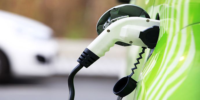
Hybrids that can't be recharged from an outlet aren't generally considered to be electric vehicles, as they rely exclusively on gasoline or diesel for energy. Plug-in hybrids, described above, are considered electric vehicles, along with battery electric and hydrogen fuel cell vehicles.Battery electric vehicles only use an electric motor and battery, eschewing conventional engines altogether. Because they don't use gas or diesel, battery electrics are often cleaner and cheaper to fuel than hybrids and conventional vehicles.
Hydrogen fuel cell vehicles power an electric motor and battery by converting stored hydrogen gas to electricity using a fuel cell. These vehicles are only beginning to come to market, but offer great potential as a low-carbon alternative to conventional cars and trucks as they have no tailpipe emissions, reduced global warming emissions, and can be refueled at a filling station similar to a gasoline vehicle.
Power unit and ERS
__________________________________________________________________________________
The internal combustion engine has always been the beating heart of a Formula 1 car, though today it represents just one element of an enormously sophisticated power unit.

Just as crucial to propulsion, and fully integrated with the turbocharged 1.6-litre V6, is an Energy Recovery System (ERS) that dramatically increases the unit’s overall efficiency by harvesting (and redeploying) heat energy from the exhaust and brakes that would usually go to waste.
The internal combustion engine itself is a stressed component within the car which is bolted to the carbon fibre 'tub'. Despite its relatively diminutive size and 15,000rpm rev limit, direct fuel injection, a single turbocharger and some remarkable engineering make it capable of producing around 700bhp.
ERS accounts for an additional 160bhp and helps ensure that the new units are not only just as powerful as the 2.4-litre V8s they succeeded, but considerably more efficient, using approximately 35 percent less fuel.
The new power units are a far cry from Formula 1 engines in the early 1950s which produced power outputs of around 100 bhp / litre (similar to what a modern 'performance' road car can manage now). That figure rose steadily until the arrival of F1 racing’s first 'turbo age' of 1.5 litre turbo engines in the 1970s when anything up to 750 bhp / litre was being pumped out. Then, once the sport returned to normal aspiration in 1989 that figure fell back, before steadily rising again. It wasn’t long before outputs crept back towards the 1000 bhp barrier, with some teams producing more than 300 bhp / litre in 2005, the final year of 3 litre V10 engines.
From 2006 to 2013, the regulations required the use of 2.4 litre V8 engines limited to 18,000rpm, with power outputs falling around 20 percent. However, the introduction of a Kinetic Energy Recovery System (KERS) in 2009, which captured waste energy created under braking and transformed it into electrical energy, ensured the teams had an extra 80bhp or so to play with for just over six seconds a lap.
Today’s ERS take the concept of KERS to another level, combining twice the power with a performance effect around ten times greater. ERS comprises two motor generator units (MGU-K and MGU-H), plus an Energy Store (ES) and control electronics. The motor generator units convert mechanical and heat energy to electrical energy and vice versa.
MGU-K (where the ‘K’ stands for kinetic) works like an uprated version of the previous KERS, converting kinetic energy generated under braking into electricity (rather than it escaping as heat). It also acts as a motor under acceleration, returning up to 120kW (approximately 160bhp) power to the drivetrain from the Energy Store.
MGU-H (where the ‘h’ stands for heat) is an energy recovery system connected to the turbocharger of the engine and converts heat energy from exhaust gases into electrical energy. The energy can then be used to power the MGU-K (and thus returned to the drivetrain) or be retained in the ES for subsequent use. Unlike the MGU-K which is limited to recovering 2MJ of energy per lap, the MGU-H is unlimited. The MGU-H also controls the speed of the turbo, speeding it up (to prevent turbo lag) or slowing it down in place of a more traditional wastegate.
A maximum of 4MJ per lap can be returned to the MGU-K and from there to the drivetrain - that’s ten times more than was possible with KERS, the ‘bolt-on’ recovery system ERS replaced in 2014. That means drivers have access to an additional 160bhp or so for approximately 33 seconds per lap.
For regulatory reasons the power unit is deemed to consist of six separate elements. These are the four ERS components, plus the internal combustion engine and the turbocharger. Should a driver use more than their permitted allocation of any one component he faces a grid penalty ranging from 10 to five places.
During a race drivers may use steering wheel controls to switch to different power unit settings, or to change the rate of ERS energy harvest. Such changes are controlled and regulated by the standard electrical control unit (ECU), mandatory on all F1 cars. But for all the things the driver can change from the cockpit, one thing he can’t do is start his own car. Unlike road cars, Formula One cars do not have their own onboard starting systems so separate starting devices have to be used to start engines in the pits and on the grid.
For safety, each car is fitted with ERS status lights which warn marshals and mechanics of the car’s electrical safety status when it is stopped or in the pits. If the car is safe, the lights - which are situated on the roll hoop and the rear tail lamp - will glow green; if not, they glow red. The lights must remain on for 15 minutes after the power unit has been switched off.
ALTERNATOR
_________________________________________________________________________________
The alternator in your car is a kind of mini electrical generator, which converts mechanical energy into electrical energy through a process known as alternating current. Without an alternator, the engine in your car would have no spark, your headlights no light, and your heater no way to keep you comfortable in the winter. The process sounds complicated, but the way an alternator works is really pretty simple.
Battery vs. Alternator
Although many people assume that a car's battery powers all those things, the truth is that the battery only does one thing other than keeping the electronics on when the engine is off: It starts the engine. And only for a limited time. Once the engine fires, the alternator takes over and provides the juice.
Automobile engines run on air, fuel, and spark. While the battery supplies the electricity needed for that initial spark, it only has enough power to get the car a few miles down the road, and that's where the alternator comes in—it continually charges the car battery while the car is in motion while also simultaneously operating all the electronic components of the vehicle. This means that while the voltage of most car batteries is 12 volts, an alternator will typically output anywhere between 13 and a half and 15 volts of electricity.
How Alternators Work to Make Electricity
The alternator is comprised of a voltage regulator and three main components: The stator, rotor, and diode. When the battery initially powers the car, the alternator belt, or V-belt, spins the pulley on the alternator, causing the rotor inside the alternator to spin very quickly. This rotor, which is basically a magnet or group of magnets, is situated inside a nest of copper wires, which are called the stator.
The process whereby electricity is generated by spinning magnets at incredibly fast speeds along a set of copper wires is called electromagnetism. The electricity harnessed this way is conducted through the copper wires to a diode, which changes the electricity from AC to DC, the current that the car battery uses.
The next step happens within the voltage regulator—a built-in component on modern alternators—which is basically a gatekeeper that will shut off the flow of power to the battery if the voltage goes above a certain level, usually 14 and a half volts, which keeps the battery from getting overcharged and burning out. As the car battery is drained, current is allowed to flow back into it from the alternator, and the cycle goes on and on.
Signs of a Bad Alternator
When a car alternator is going bad, drivers will notice a reduced capacity for electrical use, often resulting in things like dim headlights. But these clues won't last long, because a partially charged battery usually has enough power to operate things like headlights and power windows, but will fail the next time you try to start the vehicle.
There is also usually a dash board light, also known as the battery light because it's often shaped like a little battery, that will alert drivers to an alternator that is not providing enough charge to keep the system up.
:max_bytes(150000):strip_icc()/engine-compartment-172629650-5ba68e3846e0fb00508ac55f.jpg)
Operational Information
The Computer Controlled Electronic Engine
_________________________________________________________________________________
It is not generally known that the first airless injection system (i.e. not to use compressed air to atomise the fuel) was a common rail system. The invention of this system is often mistakenly credited to Doxford, but it was invented and patented by Vickers of Barrow in Furness.
In this early common rail system the engine driven fuel pumps pressurised a fuel rail to about 400 bar from which pipes led to the fuel valves operated by cams and rocking levers. Independently driven pumps were provided to prime the system for starting.
Later systems used hydraulically operated injectors, the delivery of fuel being controlled by a cam operated valve. Fuel quantity was controlled by an eccentric on the cam follower.
With the integration of industrial electronics into marine engineering systems coupled with the giant strides made in the development of computer technology, it has now become possible to re-introduce the fuel injection common rail along with other fuel injection systems, using this modern technology to time the injection of fuel without mechanical aids.
In addition to this, it has become possible to dispense with the timed camshaft altogether by using similar systems to control operation of valves and the air start system.
The two major manufacturers of two stroke crosshead engines have both introduced a camshaft-less engine. Sulzer call theirs the RT Flex engine, and MAN B&W call theirs the ME intelligent engine. Both engines use electrical and engine driven axial piston pumps to pressurise servo oil rails to 200 bar which are then used for fuel injection and exhaust valve operation. In addition MAN B&W use the servo oil to drive the cylinder lubricator units (Alpha system)
Although they both work without a camshaft and use computers to control, fuel injection, exhaust valve operation and air starting, the method of fuel injection is different.
Sulzer use a pressurised fuel rail using a set of jerk type pumps driven by a three lobe cam geared to the crankshaft. The pumps are variable delivery, based on the ZA40 fuel pump, controlled by an electrically driven fuel pump shaft linked to the engine computer.
The engine computer system known as the Wartsila Engine Control System (WECS)controls the delivery from the common rail to the individual cylinders via the volumetric injection control system which uses finely filtered engine LO pressurised by electric pumps to 200 bar.
|
When the Rail Valves are energized for injection by the Valve Driver Module, oil from the Control Rail opens the Injection Control Valves. The fuel injectors are pressurized and fuel oil pressure behind the Fuel Quantity Piston maintains this pressure at the injectors. As the Piston moves to the left a feedback signal is sent to the Cylinder Control Module.
At low engine load the control system cuts out one of the three injection valves per cylinder.
At very low load two of the three injection valves are cut out. This is used to avoid visible smoke emission and to reduce fuel consumption. It is possible to reduce engine load to 10% with engine revolutions as low as 7RPM.
|
Unlike the Sulzer RT Flex engine the MAN B&W ME engine does not operate the fuel injection on a common rail system.
Instead a solenoid operated proportioning valve (the FIVA valve - Fuel Injection Valve Activation) allows the pressurised servo oil under a hydraulic piston. This then moves the fuel pump piston upwards, raising the fuel pressure and opening the injection valves.
A nitrogen filled accumulator maintains the hydraulic servo oil pressure during the operation of the pump.
|
To be able to time the fuel injection the Control Systems must know the crank angle of the individual units. To do this two crank angle sensors are fitted at the free end of the engine. These sensors are accurate to 0.1°. Cylinder pressures and powers are continually monitored by using strain gauges built into the cylinder head, and the computer automatically compensates for twist in the crankshaft when relating crankshaft position to cylinder pressure. the systems give complete flexibility over start and end of injection and take into account fuel quality, dead time (the time between injection start command being given and actual injection), and Variable Injection Timing (VIT).
The exhaust valve actuator replaces the cam operated exhaust valve hydraulic pump on both make of camshaftless engines. Both working on a similar principle, servo oil at 200 bar is used to operate a piston which operates the exhaust valve "hydraulic push rod" The oil for operating the "hydraulic push rod" comes from the main engine LO supply via a non return valve.
|
The air start system is similar to that on a conventional engine except there is no need for a mechanically driven distributor to open the air start valves at the correct time.
Instead of a camshaft driven, reversing air start distributor, each air start valve is opened at the correct time by the engine computers sending a signal to a solenoid controlled nc (normally closed) valve.
The timing of the air start valves will vary depending on the number of cylinders, but they will be open for a long enough period to allow overlap, so that a valve opens before the previous valve closes, allowing starting from any position of rest. The nominal opening can be considered as 0° (ie TDC) and closing at 110° ATDC.
The computer knows when to send the signal because it is receiving information as to the crankshaft position from the angle encoders which measure crankshaft position and RPM.
When the engine has reached firing speed the computers shut off the air and introduce the fuel.
|
Are Engine Stop-Start (ESS) Systems Reliable?
___________________________________________________________________________________

Start. Drive. Stop. Start. Drive. Stop. It’s a relatively subtle thing that you’ll likely get used to, as the vehicle turns itself off in situations where it’d otherwise be idling. Release the brakes, and the engine is back up and running in less time than it takes to move your foot back onto the throttle pedal.
This saves fuel, and saving fuel is good
Regular reader emails indicate that a portion of the car-buying public is apprehensive about buying a vehicle with a starter that may turn the engine on and off dozens of times on a single drive. Some even report that they’ve avoided buying a vehicle with ESS to avoid future issues. Others say they deactivate the ESS system via a switch on the dashboard on every drive, to avoid wearing out the starter.
It’s born partly of a logic embodied in a favourite phrase of my father, who likes to keep things simple: “That sounds like more stuff to break.” Though he uses a different word than “stuff”.
New technology always has its skeptics, and back in the day, people probably had similar concerns about fuel injection, automatic transmissions, and power windows.
“A remote control to unlock your doors?! Imagine the repair bill when that breaks!”
Below, we’ve compiled input from some experts in the industry – including a manufacturer of ESS system components, an automaker who uses a lot of them, and some notes from our network of service technicians.
THE COMPONENT MANUFACTURE

“The ESS starter is developed for many more starting cycles (than a conventional one), since multiple warm starts are expected during each drive. The starter is optimized to start the vehicle from a warm start, and not the typical cranking cold start.”
In a cranking cold start, the engine is cold and stiff and the vehicle’s starter has to work harder, uses more power, and is under more strain. Restarting an engine that’s already warm (which is the case every time an ESS starter restarts an engine) draws less power and involves less strain.
Many ESS systems are calibrated to only begin their stop–start duties once the engine has reached operating temperature, ensuring all components within are well lubricated, and that the engine oil is at its optimal viscosity.
Think of it like jogging: a cranking cold start is like hopping out of bed in the morning and immediately running at breakneck speed, which is hard on all involved components. Conversely, a warm start, which is the key purpose of an ESS starter, is like going for a jog after a good breakfast and some warm-ups and stretches.

Though an ESS starter starts and stops an engine very frequently, the vast majority of those starts are easy ones that occur once the engine is warmed up and limber.
Like it or not, this technology is here now, and will be expanding.The notes that while many ESS systems today are running on 12-volt architecture, 48-volt systems are coming, with added benefits.
“The (upcoming) 48V starter can support various additional features, like boosting, recuperation, sailing, coasting, creeping, etc.” These additional functions all expand the operational range in which the vehicle’s engine can be switched off, saving more fuel and further reducing emissions.
“The ESS is built for lifetime use according to highest automotive standards and should have no disadvantages to the ordinary starter . “Beside the initial investment, there should be no higher cost over the lifetime.”
Continental puts their ESS starters through various durability tests, which include working the component to a high temperature before plunging it into ice water, as well as continual running of the starter at higher-than-spec speeds and currents. The ESS starters are also subjected to long-duration salt-spray tests, to assess their resistance to environmental factors.
The ESM for stop–start is more powerful than standard starters, and so components such as the pinion engagement, gears, solenoid, commutator, and motor brushes are designed to manage this increased power.”
Other modifications may include an electric auxiliary transmission pump to maintain the transmission in gear while the engine is auto-stopped, and an auxiliary water pump used to manage the system’s increased heat.


Application - HEV Start/Stop System
Start-stop technology shuts down a car’s engine when it’s not needed, for instance, when it would otherwise idle, and starts the engine again when the driver accelerates. This simple fuel-saving solution has been available for years, and is a low cost efficiency improvement. The start/stop feature alone is enough to classify a vehicle as a “micro hybrid,” and can save 5 – 10% in fuel costs.
From Battery
High Voltage DC Bus
High Voltage DC Bus
Starter Generator
HEV Start/Stop System Block Diagram
View Product List
This design is for reference only. The design, as well as the products suggested, has not been tested for compatibility or interoperability.
Protecting in-car electronics
Start-stop technology imposes several electronic design challenges because the main battery can fall as low as 6 V during engine cranking. This can disrupt the operation of in-car electronics such as the radio, climate control, GPS and interior or exterior lights. All these systems need a stable supply, or board-net voltage, of nominally 13 V to operate correctly. Hence the vehicle needs an additional subsystem, containing a power switch and associated control circuitry, both to disconnect the battery when the engine cranks and to let an auxiliary battery or dc/dc converter power the loads temporarily.
When the vehicle operates normally, the power switch in the subsystem must supply all the car’s electrical loads. At the same time, low conduction losses are imperative because the switch is on except when cranking.
IR’s 24-V AUIRF1324S-7L or 40-V AUIRF3004-7L MOSFETs are solid-state switches qualified for automotive applications. They combine a continuous drain current of 240 A (package limited) with low on-state resistance of 1.0 or 1.25 mΩ respectively to handle the maximum load current imposed by the vehicle while also minimizing system energy losses. Designers can connect several devices in parallel to further reduce on-state resistance. The MOSFETs can be controlled using a smart driver IC such as the AUIR3240S, which is designed explicitly for automotive applications.
Because the battery must remain connected when the car is parked, the combination of power switches and controller must have a low quiescent current to minimise drain on the battery. A quiescent current of around 50 µA is considered acceptable.
When the vehicle auto-start function activates engine cranking, the main battery voltage begins to fall. The power switch must turn off quickly to let the auxiliary supply maintain the board-net voltage at 13 V. This is important, because the low ohmic resistance of the power switch can let a high current flow to the main battery side with a voltage drop of only a few millivolts. The turn-on time is less critical because the current will flow in the body diode of the power switch.
It is challenging to design a driver having low quiescent current and that meets all these requirements, using discrete components. The IR AUIR3240S manages the turn-on and turn-off of the power switch. It contains a boost converter capable of operating from an input voltage in the range of 4 to 36 V, allowing continuous operation as the battery voltage falls during cranking. It also provides a MOSFET gate drive voltage of 12.5 V. The device integrates circuitry to monitor voltage and current, control on/off-time, diagnose faults and protect against thermal overload.
The IC architecture is optimized for intermittent operation, which effectively reduces current consumption to less than 50 µA. Only a few external passive components complete the design: an inductor and a capacitor for the boost converter and resistors for the diagnostic and measurement circuitry.
The internal block diagram of the controller IC includes the main dc/dc switch, K1, and freewheeling diode, D. Two comparators control the turn-on and turn-off of K1. One comparator monitors the gate voltage compared to Vcc to turn on K1. The other monitors the voltage across the shunt resistor connected to the Rs pin, which controls the turn off. The AUIR3240S can keep the MOSFET turned on while drawing very low current.
To meet automotive-industry requirements for safety-relevant systems, the AUIR3240S provides two diagnostic mechanisms to watch for excessive output current and system temperature. The IC supports thermal monitoring by providing circuitry enabling connection of an NTC device close to the MOSFET die.
Car users, pundits and legislators agree that electric cars will eventually be the norm. In the immediate future, however, start-stop technology can help reduce fuel consumption and CO2 emissions at a relatively low cost. They entail only a few modifications to the powertrain, implementing improvements in batteries, starter/alternators and electronic components, and many of these are already well developed.
All in all, rugged, reliable solid-state power switches and innovative control ICs help stop-start technology let new cars meet tightening environmental performance demands while allowing the continued use of familiar, reliable, economical and easy to use internal combustion engines.


_________________________________________________________________________________

Electronic gadgets have become an integral part of our lives. They have made our lives more comfortable and convenient. From aviation to medical and healthcare industries, electronic gadgets have a wide range of applications in the modern world. In fact, the electronics revolution and the computer revolution go hand in hand.
Most gadgets have tiny electronic circuits that can control machines and process information. Simply put, electronic circuits are the lifelines of various electrical appliances. This guide explains in detail about common electronic components used in electronic circuits and how they work.
the function & significance of the component electronic compare to automotive component :
- Capacitor in automotive ; we call condenser
- Resistor in automotive ; we call Load as like lamp , switch .
- Diode In automotive ; we call rectifier it was in dynamo starter
- Transistor In automotive ; we call regulator and amplification signal
- Inductor In automotive ; We call Coil
- Relay In automotive ; We call platinum and spark plugs
- Quartz Crystal In automotive ; We call alternator
The Elements of an Electronic Circuit
The complexity and the number of components in an electronic circuit may change depending on its application. However, the simplest circuit consists of three elements, including a conducting path, a voltage source, and a load.
Element 1: Conducting Path
The electric current flows through the conducting path. Though copper wires are used in simple circuits, they are rapidly being replaced by conductive traces. Conductive traces are nothing but copper sheets laminated onto a non-conductive substrate. They are often used in small and complex circuits such as Printed Circuit Boards (PCB).
Element 2: Voltage Source
The primary function of a circuit is to allow electric current to pass through it safely. So, the first key element is the voltage source. It is a two-terminal device such as a battery, generators or power systems that provide a potential difference (voltage) between two points in the circuit so that current can flow through it.
Element 3: Load
A load is an element in the circuit that consumes power to perform a particular function. A light bulb is the simplest load. Complex circuits, however, have different loads such as resistors, capacitors, transistors, and transistors.
Electronic Circuit Facts
Fact 1: Open Circuit
As mentioned before, a circuit must always form a loop to allow the current to flow through it. However, when it comes to an open circuit, the current can’t flow as one or more components are disconnected either intentionally (by using a switch) or accidentally (broken parts). In other words, any circuit that does not form a loop is an open circuit.
Fact 2: Closed Circuit
A closed circuit is one that forms a loop without any interruptions. Thus, it is the exact opposite of an open circuit. However, a complete circuit that doesn’t perform any function is still a closed circuit. For example, a circuit connected to a dead battery may not perform any work, but it is still a closed circuit.
Fact 3: Short Circuit
In the case of short-circuit, a low-resistance connection forms between two points in an electric circuit. As a result, the current tends to flow through this newly formed connection rather than along the intended path. For example, if there is a direct connection between the battery’s negative and positive terminal, the current will flow through it rather than passing through the circuit.
However, short circuits usually lead to serious accidents as the current can flow at dangerously high levels. Hence, a short circuit can damage electronic equipment, cause batteries to explode, and even start a fire in commercial and residential buildings.
Fact 4: Printed Circuit Boards (PCBs)
Most electronic appliances require complex electronic circuits. That’s why designers have to arrange tiny electronic components on a circuit board. It comprises a plastic board with connecting copper tracks on one side and lots of holes to affix the components. When the layout of a circuit board is printed chemically onto a plastic board, it is called a printed circuit board or PCB
Fact 5: Integrated Circuits (ICs)
Though PCBs can offer a lot of advantages, most modern instruments such as computers and mobiles require complex circuits, having thousands and even millions of components. That’s where integrated circuits come in. They are the tiny electronic circuits that can fit inside a small silicon chip. Jack Kilby invented the first integrated circuit in 1958 at Texas Instruments. The sole purpose of ICs is to increase the efficiency of the electronic devices, while reducing their size and manufacturing cost. Over the years, integrated circuits have become increasingly sophisticated as technology continues to evolve. That’s why personal computers, laptops, mobiles phones, and other consumer electronics are getting cheaper and better by the day.
modern technology, electronic circuit building process has been completely automated, especially for building ICs and PCBs. The number and arrangement of components in a circuit may vary depending on its complexity. However, it is built using a small number of standard components.


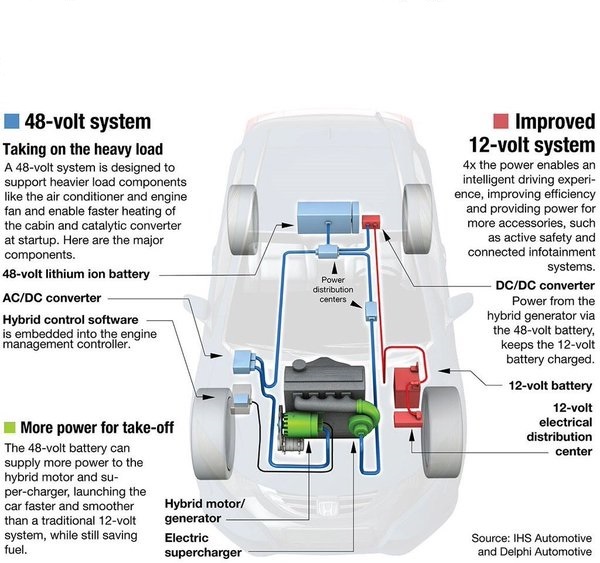
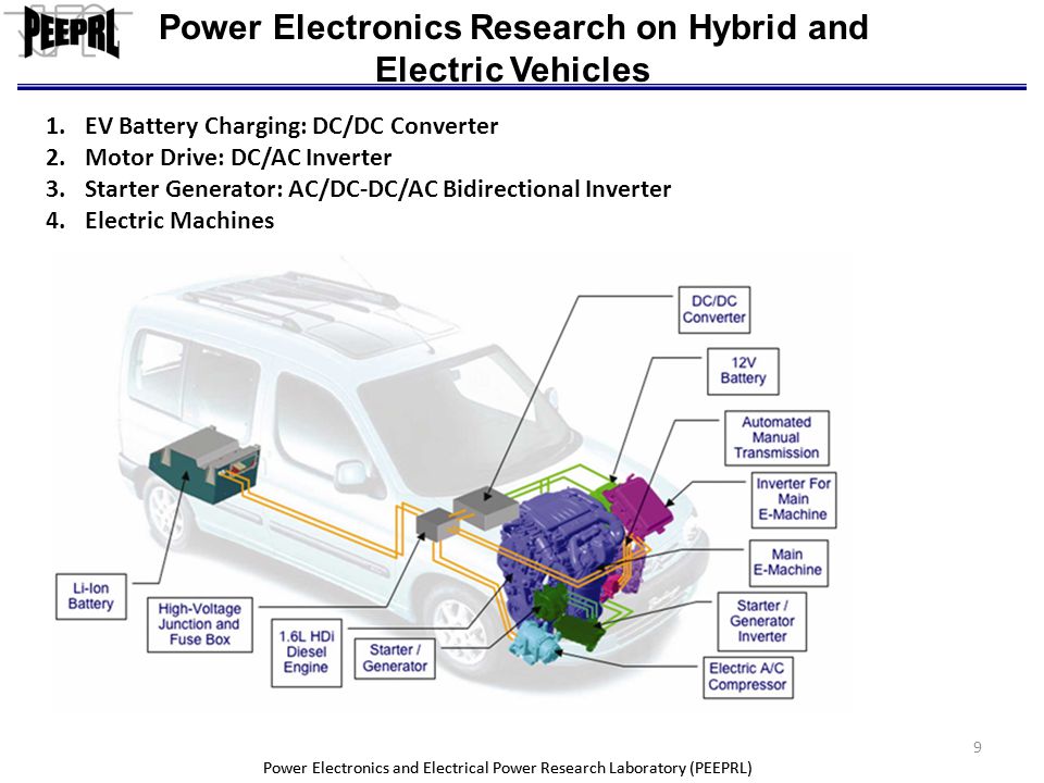
Future Automotive Electronic Systems
__________________________________________________________________________________
The future of the automotive electronic systems. Future applications of telematics are described. One of the interesting potential future developments in the application of electronics to automobiles is navigation. The fundamental control strategy for fuel metering has not changed, although the technological changes have improved the performance and reliability of the electronically controlled engine. Some of the technical improvements described in the chapter include knock control, linear solenoid idle speed control, sequential fuel injection, distributorless ignition, self-diagnosis for fail-safe operation, back-up microprocessor (MPU), and hybrid vehicles. New mechanisms and electromechanical actuators have been developed to improve volumetric efficiency via induction systems, variable valve timing, variable nozzle turbochargers, and throttle actuators.
Automotive electronics
___________________________________________________________________________________
Automotive electronics are electronic systems used in vehicles, including engine management, ignition, radio, carputers, telematics, in-car entertainment systems and others. Ignition, engine, and transmission electronics are also found in trucks, motorcycles, off-road vehicles, and other internal combustion-powered machinery such as forklifts, tractors, and excavators. Related elements for control of relevant electrical systems are found on hybrid vehicles and electric cars as well.
The development of semiconductors after WWII greatly expanded the use of electronics in automobiles, with solid-state diodes making the automotive alternator the standard after about 1960, and the first transistorized ignition systems appearing about 1955.
The availability of microprocessors after about 1974 made another range of automotive applications economically feasible. In 1978 the Cadillac Seville introduced a "trip computer" based on a 6802 microprocessor. Electronically-controlled ignition and fuel injection systems allowed automotive designers to achieve vehicles meeting requirements for fuel economy and lower emissions, while still maintaining high levels of performance and convenience for drivers. Today's automobiles contain a dozen or more processors, in functions such as engine management, transmission control, climate control,antilock braking, passive safety systems, navigation, and other functions.
Modern electric cars rely on power electronics for the main propulsion motor control, as well as managing the battery system. Future autonomous cars will rely on powerful computer systems, an array of sensors, networking, and satellite navigation, all of which will require electronics.
Automotive electronics or automotive embedded systems are distributed systems, and according to different domains in the automotive field, they can be classified into:
- Engine electronics
- Transmission electronics
- Chassis electronics
- Passive safety
- Driver assistance
- Passenger comfort
- Entertainment systems
- Electronic Integrated Cockpit systems
Engine electronics
One of the most demanding electronic parts of an automobile is the engine control unit (ECU). Engine controls demand one of the highest real time deadlines, as the engine itself is a very fast and complex part of the automobile. Of all the electronics in any car the computing power of the engine control unit is the highest, typically a 32-bit processor.A modern car may have up to 100 ECU's and a commercial vehicle up to 40.
An engine ECU controls such functions as:
In a diesel engine:
- Fuel injection rate
- Emission control, NOx control
- Regeneration of oxidation catalytic converter
- Turbocharger control
- Cooling system control
- Throttle control
- Lambda control
- OBD (On-Board Diagnostics)
- Cooling system control
- Ignition system control
- Lubrication system control (only a few have electronic control)
- Fuel injection rate control
- Throttle control
Transmission electronics
These control the transmission system, mainly the shifting of the gears for better shift comfort and to lower torque interrupt while shifting. Automatic transmissions use controls for their operation, and also many semi-automatic transmissions having a fully automatic clutch or a semi-auto clutch (declutching only). The engine control unit and the transmission control exchange messages, sensor signals and control signals for their operation.Chassis electronics
The chassis system has a lot of sub-systems which monitor various parameters and are actively controlled:- ABS - Anti-lock Braking System
- TCS – Traction Control System
- EBD – Electronic Brake Distribution
- ESP – Electronic Stability Program
- PA - Parking Assistance
Passive safety
These systems are always ready to act when there is a collision in progress or to prevent it when it senses a dangerous situation:Driver assistance
- Lane assist system
- Speed assist system
- Blind spot detection
- Park assist system
- Adaptive cruise control system
- Pre-collision Assist
Passenger comfort
- Automatic climate control
- Electronic seat adjustment with memory
- Automatic wipers
- Automatic headlamps - adjusts beam automatically
- Automatic cooling - temperature adjustment
Entertainment systems
All of the above systems forms an infotainment system. Developmental methods for these systems vary according to each manufacturer. Different tools are used for both hardware and software development.Electronic Integrated Cockpit systems
These are new generation hybrid ECUs that combine the functionalities of multiple ECUs of Infotainment Head Unit, Advanced Driver Assistance Systems (ADAS), Instrument Cluster, Rear Camera/Parking Assist, Surround View Systems etc. This saves on cost of electronics as well as mechanical/physical parts like interconnects across ECUs etc. There is also a more centralized control so data can be seamlessly exchanged between the systems.There are of course challenges too. Given the complexity of this hybrid system, a lot more rigor is needed to validate the system for robustness, safety and security. For example, if the infotainment system's application which could be running an open source Android OS is breached, there could be possibility of hackers to take control of the car remotely and potentially misuse it for anti social activities. Typically so, usage of a hardware+software enabled hypervisors are used to virtualize and create separate trust and safety zones that are immune to each other's failures or breaches. Lot of work is happening in this area and potentially will have such systems soon if not already.
Functional safety requirements
In order to minimize the risk of dangerous failures, safety related electronic systems have to be developed following the applicable product liability requirements. Disregard for, or inadequate application of these standards can lead to not only personal injuries, but also severe legal and economic consequences such as product cancellations or recalls.The IEC 61508 standard, generally applicable to electrical/electronic/programmable safety-related products, is only partially adequate for automotive-development requirements. Consequently, for the automotive industry, this standard is replaced by the existing ISO 26262, currently released as a Final Draft International Standard (FDIS). ISO/DIS 26262 describes the entire product life-cycle of safety related electrical/electronic systems for road vehicles. It has been published as an international standard in its final version in November 2011. The implementation of this new standard will result in modifications and various innovations in the automobile electronics development process, as it covers the complete product life-cycle from the concept phase until its decommissioning.
e- Key Pass
As more functions of the automobile are connected to short- or long-range networks, cyber security of systems against unauthorized modification is required. With critical systems such as engine controls, transmission, air bags, and braking connected to internal diagnostic networks, remote access could result in a malicious intruder altering the function of systems or disabling them, possibly causing injuries or fatalities. Every new interface presents a new "attack surface". The same facility that allows the owner to unlock and start a car from a smart phone app also presents risks due to remote access. Auto manufacturers may protect the memory of various control microprocessors both to secure them from unauthorized changes and also to ensure only manufacturer-authorized facilities can diagnose or repair the vehicle. Systems such as keyless entry rely on cryptographic techniques to ensure "replay" or "man-in-the-middle attacks" attacks cannot record sequences to allow later break-in to the automobile.Control electronics engineering
__________________________________________________________________________________
We must and have to develop high-level control and low-level driver software that is fully integrated into the vehicle - including hybrid technologies.
prototyping electronic control unit (ECU) based on AUTOSAR that enables fast and efficient development of control systems from initial concept to production.
Capabilities
- Engine, transmission and hybrid and electric vehicle control
- Battery management systems
- Vehicle systems including: safety sensors and actuators, instrument packs, telematics, infotainment, body and chassis controllers, lighting, convertible roof systems etc
- Electrical integration of control units into vehicle systems
- Safety-critical software and electronic systems development to ISO 26262 and other standards
- Electronic hardware design capability for prototype and production electronic solutions
- Specification management
- Electronic and mechanical design
- Control software, autocoding processes
- EMC with in-house test capability
- Design validation
- Test systems
- Autonomous & connected vehicles
- Functional safety
- Systems integration
- Batteries
- E-machines
- Power electronics
- E-drivelines
- Benchmarking
E-machine design covers all motor types and drive types including Surface Permanent Magnet (SPM), Induction Machine (IM), Interior Permanent Magnet (IPM) and Switched Reluctance (SR) machines. The Prototype designs are bespoke to the application needs and may include features such as:
- A wide speed range constant power capability
- Very high-torque at low speed from standstill for rapid engine starting
- High-efficiency output in primary operating region
- Efficiency for 10~100% speed, >20% rated torque: =>90%
Automotive electronics: What are they, and how do they differ from “normal” electronics?
__________________________________________________________________________________

Automotive electronics are specially-designed electronics intended for use in automobiles. Automotive electronics can be subjected to, and are therefore rated at, more extreme temperature ranges than commercial (i.e. normal) electronics.
Most electrical devices are manufactured in several temperature grades with each manufacturer defining its own temperature ratings. Therefore, designers and engineers must pay close attention to the actual specifications on product datasheets. The list below is an example of temperature ratings/grades. Note that the automotive grade is second only to the military grade (in terms of extreme temperature ratings):
• Commercial: 0°C to 85°C
• Industrial: -40°C to 100°C
• Automotive: -40°C to 125°C
• Military: -55°C to 125°C
Now how about to : why not just use the military grade in all applications? And there’s one simple answer: cost. We can be assured that as the temperature rating of device increases, so does its cost — sometimes significantly.
However, aside from a special temperature rating, devices that carry the term “automotive electronics” are those devices that have either been designed for or have been adapted for use in automobile applications. Categories of this include carputers, telematics, and infotainment systems.
A carputer (a combination of the words car and computer) is really nothing more than a customized PC designed to operate in a car with one or more of the following added features:
• Compact size
• Low-power requirement
• Customized components
• Video-capable (DVD)
• Music-capable (MP3)
• Bluetooth-capable
• USB-capable
• WiFi-capable
• GPS navigation
The first use of a computer in a car was for engine control. It was called the ECU computer, or the Engine Control Unit. The year was 1968 when the first ECU appeared in a Volkswagen to perform one specific function: EFI (electronic fuel injection). See Figure 1 below.

Fig. 1: Volkswagen first to use a computer in a car
Telematics (a combination of the words telecommunications and informatics) is, in a broad sense, any integrated use of telecommunications utilizing information and communication technologies—it is the technology of sending, receiving, and storing information relating to cars via telecommunication devices. The following list includes examples of communications that either use or otherwise take advantage of telematics:
• Vehicle/trailer tracking
• Wireless vehicle safety communications
• Emergency warning system for vehicles
• Intelligent vehicle technologies
• Car-sharing technologies
• Satellite navigation
• Road safety
Infotainment (a combination of the words information and entertainment) systems—also referred to as in-car entertainment (ICE) and in-vehicle infotainment (IVI)—is a collection of hardware and software in automobiles that provides audio and video content in a combination of information and entertainment. It can be argued that infotainment systems was the catalyst for transforming an ordinary car into a smart car, that is, one that can provide excellent entertainment facilities (such as ear seat entertainment) as well as provide technologies capable of driver-assistance, including assisting a driver while parking a car, alerting the driver on a congested traffic route and suggest an alternative path, and providing internet connectivity inside a car.
“Infotainment is one of the key megatrends fueling the pervasiveness of microelectronics in cars.” It’s becoming clear that drivers want to be “connected” and easily access their personal content anywhere, anytime, and on all of their devices. And today’s automotive electronics provide the means for converting the car into yet another “connected device.” “A ‘connected’ car is also more comfortable, safer, and energy efficient, having early access to important information such as weather reports, traffic jams, or road accidents.”

Fig. 3: Example of infotainment dashboard
Today’s cars can have over 50 computer systems dedicated for monitoring and/or controlling everything from ride handling, to on-board entertainment and communication systems (see Figure 4 below). Current automotive electronic semiconductor suppliers include Freescale/NXP, Renesas, Infineon, STMicroelectronics, Bosch, Texas Instruments (TI), ON Semiconductor, Toshiba, and Micron Technology .
Safety applications
Airbag System
- Airbag systems are standard in most cars and are mandatory equipment in many countries.
- Infineon’s products support scalability and flexibility for building systems from 4 to over 20 firing loops.

Fig. 5: Airbag System. Image taken from Infineon’s
Automotive 24GHz Radar System
- Short-range radar implementation.
- 24GHz radar technology for driver-assist systems such as autonomous emergency braking and blind spot detection.

Fig. 6: Radar System. Image taken from Infineon’s
Multi-Purpose Camera System
- Highly integrated, compact, and efficient camera system.
- Enables driver assistance functions including lane departure warning, forward collision warning, traffic sign recognition, and pedestrian recognition.

Fig. 7: Camera System. Image taken from Infineon’s
Tire Pressure Monitoring System
- Ensures correct tire pressure for car safety, handling, and comfortable driving.
- Increases tire lifetime of up to 30%
 Fig. 8: Tire Pressure Monitoring System
Powertrain Applications
48V Micro-Hybrid
- Start/Stop and High-Efficiency Generator
- Engine brake emulation, car sailing/coasting, electrical car launch.

Fig. 9: 48V Micro-Hybrid System.
Gasoline Direct Injection System
- Conforms to the latest emission legislation at the highest possible fuel efficiency.
- Provides enhanced measurement precision (ignition control, misfire detection)

Fig. 10 Gasoline Direct Injection System
Body Applications
LED Rear Light Module
- Integrated LED control with diagnostic and dimming capability
- Increases lifetime of LED and LED driver due to integrated protection.

Fig. 11: LED Rear Light Control.
Interior Light Control with Capacitive Touch Sensor
- Replacing mechanical switches offers cost savings.
- Robust and reliable touch sense control technology.

Fig. 12: Interior Light Control
+++++++++++++++++++++++++++++++++++++++++++++++++++++++++++++++++++++++++
If you want to read and analyze energy formation and the concept of combustion that causes energy please read my other book summary, in mode: JESIISE LOVE ADAPTER (e- JESI ISE LOVE)
Tidak ada komentar:
Posting Komentar