
DEGREE THEORY

The idea of degree theory is to give a "count" of the number of solutions of nonlinear equations but to count solutions in a special way so that the count is stable to changes in the equations. To see why the obvious count does not work well consider a family of maps ft( x) on R defined by ft( x) = x 2 - t. As we vary t,ft changes smoothly. Fort< 0, it is easy to see that ft(x) = 0 has no solution, f 0 (x) = 0 has zero as its only solution while fort> 0, there are two solutions ±Vt. Hence the numbers of solutions changes as we vary t. Hence, to obtain something useful, we need a more careful count.
A clue is that 0:: has different signs at the two solutions ±vt. Before, we proceed further, we need some notation. Assume D is a bounded open set in Rn and f : D ---+ Rn is C 1 . We say p is a regular value off if det f' (X) -I- 0 (equivalently f' ( x) is invertible ) whenever x E D and f( x) = p. One thinks of the regular points as the nice points. Note that pis a regular value if p rf. f(D). Now suppose f : D ---+ Rn is smooth, p rf. f(8D) and pis a regular value of f. Since pis a regular value off, the inverse function theorem implies that the solutions of .f(x) =pin Dare isolated in D. On the other hand {xED: f(x) = p} is compact since it is a closed subset of D. Since a compact metric space which consists of isolated points is easily seen to be finite, it follows that {xED: f(x) = p} is finite. We then define the degree of .f deg (f,p, D) to be L sign det .f'(x;) where x; are the solutions of .f(x) =pin D. I stress that we are assuming f is smooth, p rf. f( aD) and p is a regular value of f. Here and sign 0 is not defined. sign y = { 1 -1 if y > 0 if y < 0 You might ask why we assume p rf. f(8D). The reason is that, otherwise, a solution might move from inside D to out of D as we make small perturbations of f or p. In this case, we would expect that any "count" of the number of solutions might well change. Suppose pis not a regular value off (but .f is smooth and p rf. .f(oD)). We try to define deg (f,p, D)= lim deg (f,p;, D) •---oo where p; are regular values off approaching p. There are two problems with this. Firstly, we need to know that there are such regular values and secondly that the limit exists (and is independent of the choice of p;). The first problem is resolved by the following.
Sard's Theorem. Assume f : D ----+ Rn is C 1 where D is open in Rn (not necessarily bounded). Then the set of regular values off are dense in Rn. This is proved by showing that the complement of the set of regular values of f has measure zero. We only sketch the main idea. The main idea in the proof is to show that if .To tfc D is and f' ( x 0) is not invertible, then, for B a small ball center xo, f(B) is squashed close to the hyperplane f( x 0 )+ f' ( x 0 )Rn (since f is well approximated by its derivative near xo). Note that a hyperplane has zero measure. One uses this to show f(B) has much smaller measure than B if jj has small radius. To overcome the second problem is more difficult. (Note that the set of regular values off need not be connected). It turns out that the shortest proof is indirect. We consider the integral where Jf denotes the Jacobian off (where f is as above),¢> in coo on Rn, support of ¢> is contained in an n- dimensional cube C, p E int C, C II f( 8D) is empty and L = 1. Such a ¢> is said to be admissible. It is easy to find at least one admissible ¢> exists by choosing C a small cube center p. The advantage of using integrals is that they are much more regular under perturbations. We will show (rather sketch) that d( ¢>) is in fact the same as de g. To see this, note that, if ¢> 1 and are admissible with support in the same cube C, then One proves the right hand side is zero by proving that the integrand is the eli vergence of a (vector) function vanishing near 8 D and applying the eli vergence theorem. This is the messy part of the proof. This implies that d( ¢>) is independent of admissible ¢>. Secondly, note that p does not appear explicitly in the integral defining d( ¢>) and hence we deduce that d( ¢>) is locally constant in p. Thirdly, if pis a regular value of j, then d(¢>) = deg(f,p,D). To see this note that, by the implicit function theorem, f( x) = p has only a finite number of solutions {x;}7=l in D and we can choose disjoint neighbourhoods D; of x; in D 185 such that f maps D; diffeomorphically on to a neighbourhood of p and f' ( x) has fixed sign on D; (by shrinking D; is necessary). vVe than choose admissible cp such that the cube C <;;;; n.f(D;). By the change of variable theorem for integrals { cf;(.f(x))JJ(x)dx =sign JJ(x;) r cf;(z)dz lv, Jf(Di) =sign J1(x;) since support cp <;;;; f(D;) Thus h d(cf;) =!, cf;(.f(x))JJ(x)dx = L!, cf;(.f(x)JJ(x)dx D i=l D; since the integrand is zero outside Uf=1 D; k = L sign JJ(xi) i=l = deg (.f,p, D) Note that we have used that d( cp) is independent of cp to be able to choose a special ¢ and the reason the argument works is the close relation between d( cp) and the change of variable theorem. We now easily complete the proof that the degree is defined. If p is not a regular value for f. Then d( cjJ) is the same for all q near p. However, if q is a regular value, d(¢) = deg(f,q,D). Hence we see that for all regular values p; off near p, deg (f,p;,D) = d(cf;) and hence lim deg (f,p;,D) exists, as required. 1---+00 Note that we could use the interval d(¢) to define the degree but it is harder to deduce properties of the degree from this definition. 186 LECTURE 2 Assume f : Rn -----+ Rn is smooth, Dis bounded open in Rn and p tf:_ f( aD). Our proof that .lim deg (!,pi, D) has a limit if Pi are regular values off approaching Z--+00 p was rather indirect (by way of d( ¢)). There is another proof which considers two regular values Pi, Pi of f near p and studies how the solutions off( x) = tp; + (1- t)pj changes as t varies from 0 to 1. This proof while more intuitive is rather more technical. Note that the degree can also be constructed by more topological arguments. Note that by its construction deg (!, p, D) is integer valued. We now consider properties of the degree we have constructed. The basic properties are the following where we assume D is bounded open in Rn, f : D -----+ Rn is continuous and p t/:- f( aD). (i) If deg (!, p, D) "I 0, there exists x E D such that f( x) = p. (ii) (excision) If D;, i = 1, · · · , m, are disjoint open subsets of D and f( x) "I p if x ED\ U£~ 1 D;, then m deg (.f,p,D) =I: deg (f,p,D;) i=l (iii) (products) If D 1 is bounded open in Rm, g : D1 -----+ Rm is continuous and q t/:- g(8D1), then deg ((f,g),(p,q),D x DI) = deg (f,p,D) deg (g,q,D1 ). Here (!,g) is the function on Rm+n defined by (f,g)(x,y) = (f(x),g(y)) for X E Rn, y E Rm. (iv) homotopy invariance. IfF : D X [a, b] -----+ Rn is continuous and ifF( x, t) -:j:; p for x E 8D and t E [a, b], then deg (F1 ,p, D) is defined and independent of t fortE [a, b]. Here F1 is the map of D into Rn defined by F1(x) = F(x, t). Note that we have not actually defined the degree of maps f which are only continuous. The above 4 properties are first proved for smooth functions. Properties (i) - (iii) are proved first for p a regular value and the general case is proved by approximating p by regular values. In the smooth case, (iv) is proved by using the integral formula for the degree (i.e. d( ¢)) to show that deg ( Ft, p, D) is continuous 187 in t and then using that a continuous integer valued function on [a, b] is constant. Finally, iff is only continuous, deg (f, p, D) is defined to be deg (.f, p, D) where .f is a smooth function uniformly close to f on D. To show that this is independent of the choice of f one uses that, if h is another smooth approximation to j, then one can apply homotopy invariance to the smooth homotopy t.f(x) + (1 - t)h(x) for xED, t E [0, 1]. Lastly, one uses an approximation argument to extend properties (i) - (iv) from the smooth case to the continuous case. This is actually all straightforward, albeit a little tedious. This completes the construction of the degree. It is easy to deduce from the definition a number of other properties of the degree. In particular, deg (f,p, D)= deg (f(x)- p, 0, D) whenever deg (f,p, D) is defined and that deg (A, 0, D) = sign det A if A is an invertible n x n m.atrix and D is a bounded open set containing zero (and where we are identifying a matrix and the corresponding linear map). In general, one can prove many properties of the degree by first proving it for f smooth and p a regular value off and then using limit arguments. The homotopy invaria.nce property is a very important property of the degree because it often enables us to calculate the degree by deforming our map to a much simpler map. This enables us to calculate the degree of some complicated maps. As a simple application, we prove the very useful Brouwer fixed point theorem. Assume S is closed bounded and convex in Rn and f : S --+ S is continuous. Then f has a fixed point i.e. there exists xES such than x = f(x). This theorem is used in many places. For example, it is frequently used to prove the existence of periodic solutions of ordinary differential equations. To prove the theorem, we assume that int S is non-empty and 0 E int S. (It is not difficult to reduce the general case to this case using the geometry of convex sets). We assume .4(x) f:. x if X E as. (Otherwise we are finished). We use the homotopy (x, t)--+ X- tA(x). The convexity and that 0 E int S imply that x f:. tA( x) if x E S and t E [0, 1] (since if x - tA(x) = 0, x = (1 - t)O + tA(x) E int S). Thus, by homotopy invariance, 188 deg (I- A, 0, int S) = deg (J, 0 int S) = 1 # 0 and hence there exists x E int S such that x - A( x) = 0 i.e. x is a fixed point. I mention one more useful property of the degree. Firstly if D ~ Rn is bounded open and symmetric (that is x E D +----+ - x E D), 0 E D, f : D ----+ Rn is continuous and odd and if f(x) # 0 for x E 8D, then deg (f,O,D) is odd. (The most important point is that it is non-zero.) If f is smooth and zero is a regular value of f, then this is easy to prove because (f(O) = 0 and if f(x) = 0 then f( -x) = 0 and J1(x) = J1( -x) (since f is odd). The main difficulty in the general case is to prove that we can approximate a smooth odd map by a smooth odd map which has zero as a regular value. This is rather technical. This result has many uses. for example, it easily implies that a continuous odd mapping of Rm into Rn with m > n has a zero on each sphere llxll = r. We will return to uses for differential equations later. It has many other uses on the geometry of Rn. For example, it can be used to prove that iff: Rn ----+ Rn is 1-1 and continuous then it is an open map (that is, .f maps open sets to open sets). There are many other results on the computation of the degree but do not assume the degree is always easy to evaluate! 189 LECTURE 3 In this lecture, we extend the degree to infinite dimensions. It turns out that this is important for many applications. First note that we cannot expect to be able to do this for all maps. The simplest way to see this is to note that the analogue of Brouwer's fixed point theorem fails in some infinite dimensional Banach spaces. We consider the Banach space c0 of sequences (x;)~ 1 with norm ll(x;)ll = sup;;::::1lx;1. We then consider the map T: co--+ co defined by T(x1,x2,···) = (1,x1 ,x2 ···). Note that Tis an affine map. It is easy to check that T is continuous and that T maps the closed unit ball in co into itself. However, T has no fixed point in c0 because if T(x;) = (x;), then x1 = 1 and Xi+l = x; for i 2:: L Thus x; = 1 for i 2:: 1, which contradicts that (xi) E c0 . It turns out that in every infinite- dimensional Banach space there is always a closed bounded set S and a continuous map of S into itself without a fixed point. Hence to proceed further, we need a restricted class of maps. Assume that W is a closed subset of a Banach space I<. We say that A : W --+ E is completely continuous if A is continuous and if A( S) is a compact subset of E for each bounded subset S of VV. We will construct a degree for maps I- A where A is completely continuous. It turns out that many (but far from all) of the mappings occurring in applications are completely continuous. The reason that we can construct a degree for such maps is that we can approximate completely continuous maps by maps whose range lie in a finite- dimensional space. Lemma. If }( is a compact convex subset of a Banach space E and E > 0, there is a continuous map Pc : }( --+ }( such that II P,( x) - x II :::; E for x E K and the range of Pc is contained in a finite-dimensional subspace of E. 1 This is proved by noting that a compact set has a finite "2E net and using some form of partition of unity. The details are not difficult. In using this in our applications, it is useful to note that the closed convex hull of a compact set is compact. If D is bounded and open in E and A : D --+ E is completely continuous, then 190 P,A = P,oA is a continuous map such that JIP,A(x)- A(x)JI ::::; eon D and the range of P,A is contained in a finite-dimensional subspace of E. (We define I< to be the closed convex hull of A( D). If p rt (I- A)( an) and e is small, we define deg (I -A,p,D) = deg ((I -A,)JM,p,DnM) where A,= P,A,M is a finite-dimensional subspace of E containing p and the range of A,. Note that I- A, will map D n M into M. There is quite a bit to be checked here. The right hand side is defined by our earlier construction. We need to prove that the finite-dimensional degree is defined and is independent of e and the choice of M. The details are tedious but not difficult. Note that a simple compactness argument ensures that there is an a> 0 such that Jlx- A(x)ll 2: a if X E an, that our finite-dimensional degree is a degree on finite dimensional normed spaces rather than just Rn because it is easy to check that our original degree on Rn is independent of the choice of basis in Rn and that we need to prove a lemma on the finite- dimensional degree to prove that the right hand side of the definition is independent of the choice of M. By using finite-dimensional approximations and compactness arguments, it 1s not difficult to check that the four basic properties of the finite-dimensional degree have analogues here. Assume that D is bounded and open in E and A : D ~ E is completely continuous such that Xi= A(x) + p for X E an.
The following hold. (i) If deg (I- A,p,D) =/= 0, there exists xED such that x = A(x) + p. (ii) If Di, i = 1, · · · , m, are disjoint open subsets of D such that x =/= A( x) + p m if X E D\ u~l Di, then deg (I- A,p, D) = L deg (I- A,p, Di)· i=l (iii) products. If D 1 is bounded open in a Banach space F, G : Di ~ F is completely continuous and q E F such that x =/= G( x) + q for x E an1, then deg (I- (A, G), (p, q), D x Dl) = deg (I- A,p, D) deg (I- G, q, DI). (iv) homotopy invariance. If H : D x [a, b] ~ E is completely continuous and X- H(x, t) i= p for X E an, t E [a, b], then deg (I- Ht,p, D) is independent oft fortE [a,b]. Note that in (iv) it is not sufficient to assume that H is continuous and each H, is completely continuous. However this is sufficient if we also assume that Ht is uniformly continuous in T (uniformly for xED). 191 There is analogue of Brouwer's fixed point theorem, known as Schauder's fixed point theorem. Assume that D is closed and convex in a Banach space E, A is continuous, A( D) ~ D and A( D) is compact. Then A has a fixed point. The easiest way to prove this to use the lemma to find a finite dimensional approximation to which we can apply Brouwer's theorem. Nearly all the extra properties of the degree in finite dimensions have natural analogues here. The only one that is a little different is the formula for the degree of a linear map. Assume that B : E ----t E is linear and compact and I - B has trivial kernel. (Note that for linear maps complete continuity is equivalent to compactness.) The spectrum of B consists of zero plus a finite or countable sequence of eigenvalues with 0 as it only limit point. If .\; is a non-zero eigenvalue of B, the algebraic multiplicity m(.\;) of.\; is defined to be the dimension of the kernel of (.\;I- B)q for large enough q. It can be shown that m( A;) is finite and independent of q for large q. The result is then that deg (I- B,O,Eo) = (-l)I:;m(.>.;) where the summation is over the (real) eigenvalues of B in (1, oo) and E0 is the open ball of radius 8 in E. Note that the sum is finite. The proof of this is by using linear operator theory and constructing homotopies to reduce to the finite dimensional case. As a final comment, there has been a good deal of work on extending the degree to mappings only defined on closed convex subsets of Banach spaces and to evaluating degree of critical points obtained by variational methods (as in Chabrowski's lectures or Chang's book). One major difference in the extension to closed convex sets is that the formula for the degree of isolated solutions becomes rather more complicated. This is discussed in my chapter in the book of Matzeu and Vignoli. 192 LECTURE 4 In this lecture, we consider some very simple applications of the degree. We do not try to obtain the most general results. Firstly, we consider an application of Brouwer's fixed point theorem to prove the existence of periodic solutions of ordinary differential equations. Assume f : Rn+l ~ Rn is C 1 and T periodic in the last variable, i.e., f(x, t + T) = f(x, t) if x E Rn, t E R. We are interested in the existence of T periodic solutions of the equation x1(t) = f(x(t), t) (1) To do this, we let U(t,x 0 ) denote the solution of (1) with U(O,x 0 ) = x 0 (for x 0 E Rn). Standard results ensure that (1) has a unique solution satisfying the initial condition. Vl!e need to place an assumption on f which ensures that U(t, x0 ) is defined for 0 :::; t :::; T. (The only way this could fail is that the solution blows up before t = T). A sufficient condition ensuring this is true is that there is a ]{ > 0 such that llf(x, t)ll :::; Kllxll fort E [0, T] and for llxlllarge (where II II is one of the standard norms on Rn). In this case U(t,x 0 ) is continuous in t and x 0 . Since f is T periodic in t, it is not difficult to show that U ( t, x0 ) is a T periodic solution of (1) if and only if U(T, x0 ) = x 0 i.e. x 0 is a fixed point of the map x ~ U(T, x ). Hence we can hope to our earlier degree results (to the map f(x) = x- U(T,x)). The simplest rest of the this type is that if we can find a closed ball Br in Rn such that U(T,x) E B,. if x E Br then Brouwer's theorem (applied on Br) implies that the map x ~ U(T, x) has a fixed point and hence the original equation has a T periodic solution. For example, the inclusion condition on Br holds if < f(x, t), x > < 0 for llxll = r and 0 :::; t :::; T (where <, > is the usual scalar product on Rn and we must use the norm induced by the scalar product). Before we look at the second example, I need one very useful consequence of degree theory. Assume that E is a Banach space and H : E X [0, 1] ~ E is completely continuous, the map x ~ H( x, 0) is odd and there is an R > 0 such that x #- H(x, t) if llxll = Rand t E [0, 1]. Then the equation x = H(x, 1) has a 193 solution. This is proved by noting that by homotopy invariance deg (I- H(, 1),0,ER) = deg (I- H( ,O),O,ER)-=/= 0 by the result on the degree of odd mappings. This is a very nice theorem because the statement is very simple and it is very widely applied. In practice, one usually establishes for a largeR that x-=/= H(x, t) if t E [0, 1] and llxll 2: R. In other words, one is proving that any solution of x = H(x, t) satisfies llxll :SR. In practice, this is usually by far the most difficult step in verifying the assumption of the result above. Such a result is called an a priori bound. In some of the lectures on partial differential equations, I am sure you have discussed the problem of obtaining a priori bounds. In fact, the above result often reduces the proof of the existence of a solution of a partial differential equation to the proof of a priori bounds in a suitable Banach space. (The choice of a suitable Banach space is not always simple). vVe give a very simple application of the result above which requires few technicalities. Assume Q is a bounded domain in Rn with smooth boundary and g : R----+ R is continuous such that y- 1g(y)----+ a as IYI----+ oo where a is not an eigenvalue of -tl under Dirichlet boundary conditions on D. We prove that the equation -tlu(x) = g(u(x)) inn u(x) = 0 on on (2) has a solution. By a solution we mean a function in W 2'P(Q) n C(D) which satisfies the equation almost everywhere. (It will be a classical solution if g is a little more 1 regular). It is convenient to work in the space W 2,P(fl) with p > 2n (and p > 1 ). By the Sobolev embedding theorem, this ensures that W 2,P(Q) ~ C(TI). We write K to denote the inverse of -6 under Dirichlet boundary conditions. We define G: C(TI)----+ C(TI) by (G(v.))(x) = g(u(x)). Then (2) is equivalent to the equation ·u = KG( tl ). Thus (2) becomes a fixed point problem. KG is easily seen to be completely continuous since we can think of KG as the composite J( o go i where i is the natural inclusion of W 2,P(fl) into C(TI), since i is compact, since G is continuous and since J{ is a continuous map of LP(fl) into W 2,P(Q). (The latter is 194 a regularity result for the Laplacian.) Lastly, if we define H: W 2 •P(SZ) x [0, 1] ~ W 2 •P(SZ) by H(u, t) = K(tG(u) + (1 - t)au) it is fairly easy to prove that the assumption of the above result hold and thus (2) has a solution. (The a priori bound corresponds to proving a bound for solutions of We omit the details. -.6-u = tg(u) + (1- t)au inn u = 0 on an.) In general in partial differential equations, one often has to choose the spaces carefully especially if the equations are nonlinear in derivatives in u. (In fact, these methods run into severe difficulties if the equations are highly nonlinear.) The methods also tend to run into difficulties if n is not bounded because the complete continuity fends to fail. There have been many attempts to define degrees for mappings which are not completely continuous to try to overcome this last problem. Some of these are discussed in Ize's chapter in the book of Matzeu and Vignoli. Thirdly, I obtain a result on Banach spaces though it could be very easily applied to ordinary and partial differential equations. In many applications, there is a rather trivial solution of the problem and we want to look for other solutions. For simplicity, assume that the trivial solution is zero. Hence, we assume that E is a Banach space, A : E ~ E is completely continuous, A(O) = 0 and we look at the equation x = AA( x ), (A might correspond to some physical parameter.) Our assumptions ensure 0 is a solution of the equation for all A and we look for other solutions. We assume that there is a linear mapping B on E such that IIA(x)- Bxll/llxll ~ 0 as x ~ 0. (B is in fact the derivative of A at zero in a certain sense. One can in fact define a calculus on Banach spaces). It is not difficult to prove that B is compact (since A is completely continuous). Assume Il-l is a non-zero eigenvalue of B of odd algebraic multiplicity. One can then prove that there are solutions (x,A) of x = AA(x) with x =/:- 0 and llxll + lA -Ill arbitrarily small. One usually says that ( 0, 1-l) is a bifurcation point. The interest here is that the main assumption (that 1-l has odd multiplicity) is purely on the linear part of A. 195 I omit the proof but the key ideas are the formula. for the degree of a. linear map and that if T =f. 0 is small and 8 is very small compared with T, deg (I- (f.-L + T )A, 0, E0 ) = deg (I- (f.-L + r)B, 0, Eo) and we can evaluate the right hand side. It turns out that much more is true. There is a connected set of solutions of x = >.A( x) in E x R with x =f. 0 which starts at (0, f.-L) (as above) and continues rather globally (that is to points where xis not small or>. is not close to f.-L). This can be found in Brown's book. Lastly, in many applications, the problem may require that we only look for nonnegative solutions of our equation. Thus it might be natural to look for solutions u of an elliptic equation which satisfy u( x) ~ 0 on n (for example if u represents a population). Thus it is often natural to look at problems on convex sets such as {u E C(f!): u(x) ~ 0 on n} rather than the whole space.
A.XO Degree of a continuous mapping
____________________________________________________________________________________
In topology, the degree of a continuous mapping between two compact oriented manifolds of the same dimension is a number that represents the number of times that the domain manifold wraps around the range manifold under the mapping. The degree is always an integer, but may be positive or negative depending on the orientations.
The degree of a map was first defined by Brouwer,[1] who showed that the degree is homotopy invariant (invariant among homotopies), and used it to prove the Brouwer fixed point theorem. In modern mathematics, the degree of a map plays an important role in topology and geometry. In physics, the degree of a continuous map (for instance a map from space to some order parameter set) is one example of a topological quantum number.

A degree two map of a sphere onto itself.
Definitions of the degree
From Sn to Sn
The simplest and most important case is the degree of a continuous map from the -sphere to itself (in the case , this is called the winding number):


Let be a continuous map. Then induces a homomorphism , where is the th homology group. Considering the fact that , we see that must be of the form for some fixed . This is then called the degree of .


Between manifolds
Algebraic topology
Let X and Y be closed connected oriented m-dimensional manifolds. Orientability of a manifold implies that its top homology group is isomorphic to Z. Choosing an orientation means choosing a generator of the top homology group.
A continuous map f : X→Y induces a homomorphism f* from Hm(X) to Hm(Y). Let [X], resp. [Y] be the chosen generator of Hm(X), resp. Hm(Y) (or the fundamental class of X, Y). Then the degree of f is defined to be f*([X]). In other words,
![f_{*}([X])=\deg(f)[Y]\,.](https://wikimedia.org/api/rest_v1/media/math/render/svg/6570acd772f92e73694a87741afd26738a3db23a)
If y in Y and f −1(y) is a finite set, the degree of f can be computed by considering the m-th local homology groups of X at each point in f −1(y).
Differential topology
In the language of differential topology, the degree of a smooth map can be defined as follows: If f is a smooth map whose domain is a compact manifold and p is a regular value of f, consider the finite set

By p being a regular value, in a neighborhood of each xi the map f is a local diffeomorphism (it is a covering map). Diffeomorphisms can be either orientation preserving or orientation reversing. Let r be the number of points xi at which f is orientation preserving and s be the number at which f is orientation reversing. When the domain of f is connected, the number r − s is independent of the choice of p (though n is not!) and one defines the degree of f to be r − s. This definition coincides with the algebraic topological definition above.
The same definition works for compact manifolds with boundary but then f should send the boundary of X to the boundary of Y.
One can also define degree modulo 2 (deg2(f)) the same way as before but taking the fundamental class in Z2 homology. In this case deg2(f) is an element of Z2 (the field with two elements), the manifolds need not be orientable and if n is the number of preimages of p as before then deg2(f) is n modulo 2.
Integration of differential forms gives a pairing between (C∞-)singular homology and de Rham cohomology: , where is a homology class represented by a cycle and a closed form representing a de Rham cohomology class. For a smooth map f : X→Y between orientable m-manifolds, one has


![\langle f_{*}[c],[\omega ]\rangle =\langle [c],f^{*}[\omega ]\rangle ,](https://wikimedia.org/api/rest_v1/media/math/render/svg/9ba157f0011c4ea3d7e0ff392ff0e2a8e22aea2f)
where f* and f* are induced maps on chains and forms respectively. Since f*[X] = deg f · [Y], we have

for any m-form ω on Y.
Maps from closed region
If is a bounded region, smooth, a regular value of and , then the degree is defined by the formula


where is the Jacobi matrix of in . This definition of the degree may be naturally extended for non-regular values such that where is a point close to .


The degree satisfies the following properties:
- If , then there exists such that .
- for all .
- Decomposition property:


- , if are disjoint parts of and .


- Homotopy invariance: If and are homotopy equivalent via a homotopy such that and , then
- The function is locally constant on


These properties characterise the degree uniquely and the degree may be defined by them in an axiomatic way.
In a similar way, we could define the degree of a map between compact oriented manifolds with boundary.
Properties
The degree of a map is a homotopy invariant; moreover for continuous maps from the sphere to itself it is a complete homotopy invariant, i.e. two maps are homotopic if and only if .


In other words, degree is an isomorphism between and .
![{\displaystyle [S^{n},S^{n}]=\pi _{n}S^{n}}](https://wikimedia.org/api/rest_v1/media/math/render/svg/caf0a846af44874d7435d84648af71362657922b)

Moreover, the Hopf theorem states that for any -dimensional closed oriented manifold M, two maps are homotopic if and only if


A self-map of the n-sphere is extendable to a map from the n-ball to the n-sphere if and only if . (Here the function F extends f in the sense that f is the restriction of F to .)


In mathematics, topological degree theory is a generalization of the winding number of a curve in the complex plane. It can be used to estimate the number of solutions of an equation, and is closely connected to fixed-point theory. When one solution of an equation is easily found, degree theory can often be used to prove existence of a second, nontrivial, solution. There are different types of degree for different types of maps: e.g. for maps between Banach spaces there is the Brouwer degree in Rn, the Leray-Schauder degree for compact mappings in normed spaces, the coincidence degree and various other types. There is also a degree for continuous maps between manifolds.
Topological degree theory has applications in complementarity problems, differential equations, differential inclusions and dynamical systems.
In geometry, the density of a star polyhedron is a generalization of the concept of winding number from two dimensions to higher dimensions, representing the number of windings of the polyhedron around the center of symmetry of the polyhedron. It can be determined by passing a ray from the center to infinity, passing only through the facets of the polytope and not through any lower dimensional features, and counting how many facets it passes through. For polyhedra for which this count does not depend on the choice of the ray, and for which the central point is not itself on any facet, the density is given by this count of crossed facets.
The same calculation can be performed for any convex polyhedron, even one without symmetries, by choosing any point interior to the polyhedron as its center. For these polyhedra, the density will be 1. More generally, for any non-self-intersecting (acoptic) polyhedron, the density can be computed as 1 by a similar calculation that chooses a ray from an interior point that only passes through facets of the polyhedron, adds one when this ray passes from the interior to the exterior of the polyhedron, and subtracts one when this ray passes from the exterior to the interior of the polyhedron. However, this assignment of signs to crossings does not generally apply to star polyhedra, as they do not have a well-defined interior and exterior.
Tessellations with overlapping faces can similarly define density as the number of coverings of faces over any given point.

The boundary of the regular enneagram {9/4} winds around its centre 4 times, so it has a density of 4.
Polygons
The density of a star polygon is the number of times that the polygonal boundary winds around its center; it is the winding number of the boundary around the central point.
For a regular star polygon {p/q}, the density is q.
It can be visually determined by counting the minimum number of edge crossings of a ray from the center to infinity.
Polyhedra
 |  |
| The nonconvex great icosahedron, {3,5/2} has a density of 7 as demonstrated in this transparent and cross-sectional view on the right. | |
Arthur Cayley used density as a way to modify Euler's polyhedron formula (V − E + F = 2) to work for the regular star polyhedra, where dv is the density of a vertex figure, df of a face and D of the polyhedron as a whole:
- dv V − E + df F = 2D [2]
For example, the great icosahedron, {3, 5/2}, has 20 triangular faces (df = 1), 30 edges and 12 pentagrammic vertex figures (dv = 2), giving
- 2·12 − 30 + 1·20 = 14 = 2D.
This implies a density of 7. The unmodified Euler's polyhedron formula fails for the small stellated dodecahedron {5/2, 5} and its dual great dodecahedron {5, 5/2}, for which V − E + F = −6.
The regular star polyhedra exist in two dual pairs, with each figure having the same density as its dual: one pair (small stellated dodecahedron—great dodecahedron) has a density of 3, while the other (great stellated dodecahedron–great icosahedron) has a density of 7.
Hess further generalised the formula for star polyhedra with different kinds of face, some of which may fold backwards over others. The resulting value for density corresponds to the number of times the associated spherical polyhedron covers the sphere.
This allowed Coxeter et al. to determine the densities of the majority of the uniform polyhedra.[3]
For hemipolyhedra, some of whose faces pass through the center, the density cannot be defined. Non-orientable polyhedra also do not have well-defined densities.
Polychora
There are 10 regular star polychora or 4-polytopes (called the Schläfli–Hess polychora), which have densities between 4, 6, 20, 66, 76, and 191. They come in dual pairs, with the exception of the self-dual density-6 and density-66 figures.
B. XO
Electronic Engineering with Space Systems
______________________________________________________________________________________
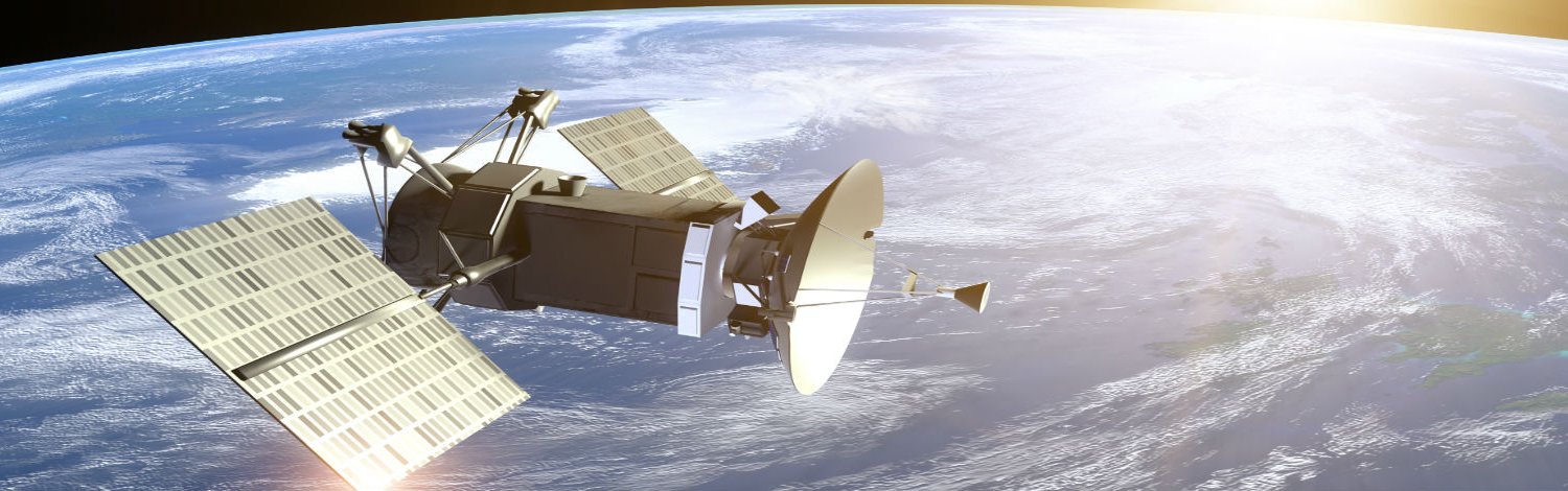
Electronic Engineering designs and builds innovative commercial satellites which are launched into orbit – having pioneered the small satellite industry nearly 40 years ago.
We will build a core knowledge in electronics and programming, and learn the fundamentals of space systems, satellite engineering, power and control, and space mission design.


Space Solutions
Satellite communications and astronomy technology and in satellite communication antenna design and a trusted ground station specialist. .
The ground station receives data from Earth Observation satellites for the purpose of monitoring

Recent and upcoming deployments of satellite laser communication systems are bringing Internet-like speeds for data transmission in space. The result could be a revolution in communication, both on Earth and across the solar system.
Laser communications through optical fibers move tens of terabits of data every second between cities and across oceans. But for the majority of Earth’s surface, where running fiber is impractical physically or financially, communication satellites in space provide connectivity—to remote ground users and also to mobile platforms such as aircraft, ships and even other satellites. These links rely on radio-frequency (RF) communications, which, while reliable, are orders of magnitude slower in moving data than optical fiber links, and have issues related to antenna footprint, power requirements and limited available spectrum.
The potential for the laser to overcome these issues in space was realized soon after its invention, although its special properties introduced new issues, such as the pointing and tracking of narrow beams over great distances while overcoming cloud cover, turbulence and other hurdles introduced by the atmosphere. Although the first laser communication systems were demonstrated in space in the 1990s, it is only recently that the technology, reliability and economics of photonic components have combined with the need for more bandwidth to push these systems more broadly into operation. The U.S. National Aeronautics and Space Administration (NASA) and the European Space Agency (ESA) are now deploying their first operational systems, which could pave the way for later commercial suppliers and, in future years, revolutionize communication both across the globe and across the solar system.
This article offers an update on recent developments and next steps in laser-based communications in space. It focuses especially on efforts at NASA, which—while a somewhat late entrant in this game—has lately shown rapid progress, culminating in a recent demonstration of a 622-Mb/s error-free data downlink from the moon to the Earth in 2013. More recently, NASA has been investigating new space-to-space and space-to-ground applications closer to Earth. In both realms, progress in terrestrial optical technology continues to push the limits of what can be done in space.
An opportunity to move beyond radio
RF communications have become a bottleneck for moving data at Internet speeds in space. The centimeter-long wavelengths of microwaves in high-frequency RF transmission bands, such as Ka-band at 26 GHz, result in widely diffracting beams that spread over hundreds of kilometers on the Earth when transmitted over 39,000 km from a satellite above in geosynchronous orbit (GEO). Increasing data transmission to speeds in excess of 1 Gb/s require a more concentrated signal at the target, which for RF systems means transmission antennas larger than a meter to narrow the beam, and higher transmit powers to deliver the same energy per bit to the receiver. The spatial overlap among users of RF’s wide beams also means that RF users must acquire, and often pay for, a license for a specifically allocated frequency band to minimize interference. Competition for RF spectrum is fierce; licensing can be expensive and complex; and individual nations tend to view the RF spectrum in their territory as a “natural resource.”
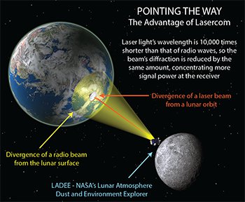
Free-space optical communication (FSOC) using lasers offers the promise of breaking through that RF bottleneck. Laser transmitters, at wavelengths some 10,000 times shorter than RF waves, result in beams that are far narrower for the same unit aperture size—providing more concentrated communications power at the receiver with lower required transmitted power from smaller, lighter apertures. The upshot is a lower size, weight and power requirement for transmit and receive apertures of a laser communications terminal. Perhaps just as important, there is almost no spatial overlap among various users, so the FSOC optical spectrum is at present unregulated—a significant advantage for space-based users.
Yet FSOC also has its own distinct challenges. Signals from space to Earth need to cross mostly cloud-free zones, which raises questions about availability. Moreover, atmospheric turbulence can cause large and sudden drops of signal (or “fades”) that can last for many milliseconds, and may also require adaptive optics to improve coupling into single-mode fibers for high-bandwidth phase-sensitive detection. Perhaps most daunting, the extremely narrow divergence of the beams introduces challenges for their pointing, acquisition and tracking across the vast distances of space.
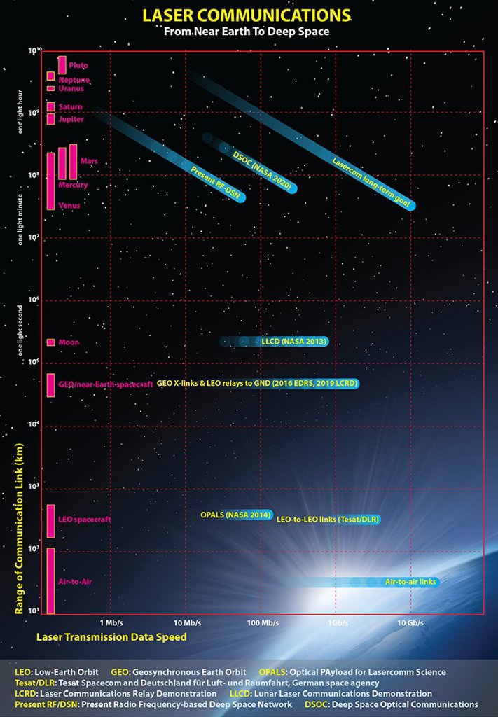
Illustration by Phil Saunders / Source: Don Boroson, MIT Lincoln Laboratory
Laser communication’s first steps in space
The first efforts in space-based laser communications, achieved by Japan and Europe, showed some success in overcoming these hurdles. Japan’s 1-Mb/s laser link to ground from the ETS-VI satellite in GEO in 1994—the first successful demonstration—was followed in 2001 by ESA’s SILEX/Artemis link demonstrations from GEO to ground and from GEO to low-Earth orbit (LEO). These initial experiments successfully demonstrated pointing, acquisition and tracking of narrow laser beams between spacecraft and directly to Earth stations, laying the groundwork for future systems in both Europe and Japan.
Development of FSOC flight systems continued in the early 2000s. The U.S. government launched the GEOLite laser communications mission in 2001. In 2008, the German Aerospace Center demonstrated a data rate of 5.6 Gb/s across 4,000-km crosslinks in space between its TerraSAR-X satellite and a corresponding terminal on the NFIRE spacecraft managed by the U.S. Department of Defense. Europe is now building on that experience to provide up to 1.8 Gb/s of laser-driven bandwidth to its Earth-observing Sentinel satellites in LEO, which will be the first operational laser communication users of the European Data Relay Satellite (EDRS) system, launching into GEO in 2016.
The economics of space laser communications changed significantly with the growth of terrestrial optical-fiber communications in the early 2000s.
The U.S. space agency has followed a more tentative path for laser communications in space. Although NASA initiated multiple efforts during the 1980s and 1990s, all were eventually cancelled due to growth in costs and the difficulty of obtaining reliable photonic components for use in space. But the economics of space laser communications changed significantly with the growth of terrestrial optical-fiber communications in the early 2000s, which suddenly boosted the availability of high-performance, low-cost components such as stable and efficient distributed-feedback (DFB) lasers, low-loss LiNbO3 modulators, and high-power and low-noise erbium-doped fiber amplifiers (EDFAs), all in the 1550-nm wavelength band. And the stringent environmental and reliability requirements of the Telcordia certifications, which govern terrestrial optical-communications equipment, are well-aligned with those for spaceflight.
From moon to Earth: NASA’s LLCD mission
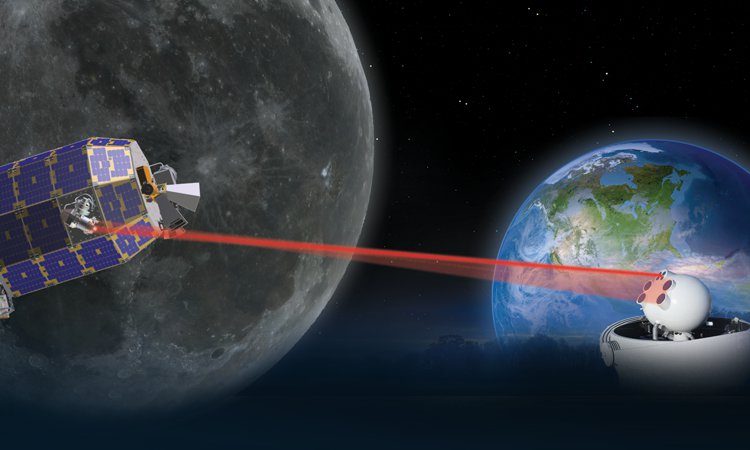
NASA’s approach has been to leverage this Earth-based development for space, purchasing commercial components and, via rigorous space-qualification testing, moving them into new, reliable and lower-cost laser communications systems for both deep space and near Earth. Using that approach, NASA demonstrated its first laser communication system in space in 2013, with the Lunar Laser Communications Demonstration (LLCD) mission, aboard the Lunar Atmosphere Dust and Environment Explorer (LADEE). The mission broke new ground in a number of areas:
Longest-range dedicated optical communications link. LLCD demonstrated error-free data downlink rates of up to 622 Mb/s from the moon at a distance of some 400,000 km—ten times the range of earlier GEO-to-ground experiments, and thus overcoming a link loss that is 100 times greater. This included error-free operation through the turbulent atmosphere.
High data rates. LLCD was an order of magnitude higher in data rate than the best Ka-band radio system flown to the moon (100 Mb/s) on the 2009 Lunar Reconnaissance Orbiter.
High-definition video link. LLCD also demonstrated a 20-Mb/s uplink, which was used to transmit error-free high-definition video to and from the moon, a communication capability crucial to possible efforts to send humans beyond low-Earth orbit.
Pinpoint ranging. LLCD’s communication system provided simultaneous centimeter-class precision ranging to the spacecraft, which can be used to improve both spacecraft navigation and the gravity models of planetary bodies for science.
Low size, weight and power. LLCD’s space-based laser terminal required only half the mass (30.7 kg) and 25 percent less power (90 W) than the Lunar Reconnaissance Orbiter RF system (61 kg and 120 W, respectively).
The LLCD mission’s real breakthrough, however, was its demonstration that such a system could return real, high-value science data from the LADEE’s instruments as they probed the moon. The LLCD space terminal and primary ground terminal—both designed, built and operated by the Massachusetts Institute of Technology (MIT) Lincoln Laboratory—showed near-instantaneous laser link acquisition on every possible pass, followed by closed-loop tracking of the 15-microradian uplink and downlink beams. Data was imparted with pulse-position modulation (PPM) of an amplified single-frequency laser, then transmitted across the vast distance to the ground receiver through narrowband spectral filtering, in front of a state-of-the-art photon-counting detector. This device consisted of 16 superconducting nanowire detector arrays (SNDAs), and is so sensitive that only two received photons were required for every error-free bit detected.
SNDAs are also large enough to be efficiently coupled to a multimode optical fiber, which in turn is large enough to collect the signal spot—blurred due to atmospheric turbulence—at the telescope focus. Powerful error-correcting codes mitigated atmospheric scintillation or “signal fades,” as did a channel interleaver that partitions and distributes the “code words” in time on a scale much longer than the length of the fades, so that only a fraction of any given code word is lost. The code words are then re-assembled at the receiver, where the decoder finds and corrects the parts of the code word lost in the fade.
These techniques provided error-free data under a range of conditions, including through thin clouds, while LADEE and the moon were less than 5 degrees above the horizon—that is, through hundreds of kilometers of atmosphere—and even during daylight, while the LADEE spacecraft was within 3 degrees of the sun as seen from the ground station.
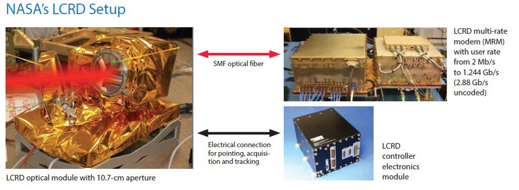
NASA’s LCRD Setup: (Left) LCRD optical module with 10.7-cm aperture, (right, top) LCRD multi-rate modem (MRM) with user rate from 2 Mb/s to 1.244 Gb/s (2.88 Gb/s uncoded) and (right, bottom) LCRD controller electronics module. [Enlarge image]
From demo to operation: The LCRD mission
The LLCD mission’s capabilities proved comparable to those of NASA’s venerable, RF-based Deep Space Network (see Optics & Photonics News, June 2014, p. 44), and provided a strong case for laser communications as a viable operational complement to the RF infrastructure. Unfortunately, however—by design—LLCD’s operations were limited to three months, and officially ended with the planned impact of the LADEE spacecraft on the moon in April 2014.
The next step for NASA will be a longer-term demonstration of FSOC in space, in the form of the Laser Communications Relay Demonstration (LCRD). Slated to fly as a hosted payload on a commercially built satellite launching in mid-2019, LCRD is designed to demonstrate high-bandwidth, bidirectional optical communications relay services between geosynchronous orbit (GEO) and Earth—and to develop and demonstrate reliable optical relay services from GEO over a time frame of two to five years.
The LCRD payload is currently being built at NASA’s Goddard Space Flight Center in Greenbelt, Maryland, USA. The payload consists of two independent laser communication terminals, which are connected via a new electronic switch to provide high-speed frame switching and routing between the two optical space terminals (OSTs) while also serving as the interface to the host spacecraft. Each OST, based on the MIT Lincoln Laboratory’s design for the earlier LLCD, includes a copy of an optical module with a gimbaled, inertially stabilized 10.7-cm telescope, along with a copy of the pointing, acquisition and tracking controller electronics, using commercially available equipment.
LCRD will also fly a new multi-rate modem (MRM) design to generate user data rates from 2 Mb/s up to 1.244 Gb/s via a differential phase shift-keyed (DPSK), burst-mode modulated beam at 1550 nm. And, as with LLCD, LCRD will leverage commercially available components from the optical fiber telecommunications industry: DFB master oscillator, high-power EDFA in the transmitter, low-noise EFDA preamp for the receiver, and many fiber-coupled optical isolators, wavelength multiplexers, filters and even monitor photodiodes.
Managing clouds and turbulence
To maximize availability due to cloud cover, the system will communicate with optical ground stations in two generally cloud-free zones—the NASA/Jet Propulsion Laboratory (JPL) telescope facility on Table Mountain, California; and the White Sands telescope facility near Las Cruces, New Mexico—with each station fully instrumented to characterize the local atmospheric stability and meteorological conditions.
The ground stations will be fitted with adaptive optics to actively compensate for atmospheric turbulence and to allow for coupling of the weak LCRD downlink signal into a single-mode optical fiber that will lead to the ground modem receiver. Unlike the LLCD demonstration, single-mode fiber is required, since demodulation of the DPSK signal through narrowband delay-line, Mach-Zehnder interferometric filters requires spatial coherence. Each ground modem will support full user-rate (1.244 Gb/s) duplex communications with the LCRD orbiting terminals; the received data will be delivered via optical fiber to the LCRD Mission Operations Center in White Sands for analysis.
LCRD’s goals over its multiyear operation are to measure and characterize the system performance across a variety of atmospheric conditions, while developing new software and operational procedures to adapt to them. These may include buffering data via the disruption-tolerant network (DTN) protocol for short outages, or performing fast handoffs between the two ground stations to mitigate longer outages due to passing clouds that might block the beam. The system will also provide an on-orbit capability to test and demonstrate new modulation schemes, as each modem is software defined and thus reprogrammable in orbit.
The culmination of the LCRD mission will be a demonstration of a “space relay” communications link from a spacecraft in low Earth orbit (LEO) up through LCRD in GEO and then down to the ground. Specifically, NASA is developing a new optical terminal to demonstrate on the international space station (ISS) in 2020 that is interoperable with LCRD for future space users in LEO or higher. This next-generation terminal will leverage recent developments in integrated photonics, which should reduce the size, weight, power and cost of the flight modem by an order of magnitude relative to RF systems. The new terminal may even replace the current LCRD terminal design for GEO if radiation requirements can be met.
If all goes according to plan, LCRD will allow service at data rates of up to 1.244 Gb/s to NASA’s next-generation Earth-orbiting scientific satellites. Those capabilities have positive implications not only for NASA but for other international space agencies and commercial space companies, which will receive access to the program as guest investigators.
 Integrated photonics in space communications
Powered by recent developments in nanostructures, metamaterials and silicon waveguides, integrated photonics could have a significant impact in the evolution of space-based laser communications. The lithographic techniques to create a photonic integrated circuit (PIC)—analogous to CMOS technology, but with photonic components replacing electrical traces—can realize hundred-fold reductions in size, mass, power and especially cost, because the PICs can be printed en masse. While PIC development is currently driven by the need for lower-footprint optical interconnects and transmission in data centers, their attributes are also critical to spreading free-space laser communications in the future.
NASA plans to place a PIC in the heart of its Integrated LCRD LEO User Modem and Amplifier (ILLUMA), leveraging access to custom device fabrication through the newly inaugurated AIM Photonics public-private partnership, sponsored by the DoD and currently managed by the State University of New York (SUNY). This technology should drive the eventual cost of the ILLUMA and other FSOC modems to well below that of today’s RF modems, allowing this technology to become ubiquitous in the space data links of the future.
(Above) PIC image courtesy of Photonic Integration Group, Eindhoven University of Technology
Lasers to deep space and beyond
The 2013 success of LLCD also provided new impetus to laser communications in another realm: deep space. NASA’s Space Technology directorate and Space Communications and Navigation (SCaN) program are now teaming to bring the agency’s Deep-Space Optical Communications (DSOC) effort to “Technology Readiness Level 6”—meaning a prototype unit fully ground-tested to space environmental levels, a.k.a., “shake and bake”—by the end of fiscal 2017, as a precursor to flight of a working laser communication system on the upcoming Discovery mission scheduled for 2020.
NASA JPL’s DSOC is designed to work from near-Earth asteroids out to Jupiter, and could deliver data at speeds of more than 250 Mb/s from Mars at opposition (0.42 AU, or 63 million km), while amounting to only 25 kg of mass and consuming only 75 W of power. But DSOC will face substantial additional challenges that LLCD did not—including a link that is 1,000 times farther from Earth, with a million times greater link loss; a required kilowatt-class uplink beam from the ground; development of a new photon-counting detector array on the spacecraft to see and locate that uplink beam; and the need for an order-of-magnitude improvement in inertially stabilized beam pointing and larger point-ahead angles for the downlink beam.
DSOC will also require larger receiver apertures on the ground than LLCD. NASA is studying development of a 12-m telescope for that purpose, though plans at present are to use the venerable 5-m Hale telescope on Mount Palomar to capture more than 100 Mb/s from Mars at opposition. Even that rate, however, constitutes an improvement of more than an order of magnitude from the highest RF data rate previously demonstrated from Mars—6 Mb/s from the Ka-band transmitter on the Mars Reconnaissance Orbiter. Hence, DSOC could constitute a profound shift in possibilities for the Mars science community.
Finally, commercial companies seeking to improve Internet bandwidth worldwide have a significant interest in FSOC. The governments of the world are leading the way on this technology by investing in the initial infrastructure while retiring the technical risks. If the promise of integrated photonics can truly be realized to drive the costs of FSOC to well below those of RF systems, then commercial networks of “fiber-in-the-sky” may soon follow, and lead to yet another communications revolution in the very near future.
C.XO
15 Degree Paths for Out-of-This-World
_____________________________________________________________________________________science, engineering, technology or communications, you can use any of the 15 degree paths
1. Astronomy

IMAGE SOURCE: Pixabay, public domain.
Astronomy is the scientific study of the stars, planets and other bodies that make up the universe. The scientists who work in this field, called astronomers, use data to develop theories about how the universe operates and when and how the celestial bodies came into existence.
2. Physics

IMAGE SOURCE: Pixabay, public domain
If you’ve ever wondered how the universe works, studying physics can help you learn the answers. Physics is the scientific study of matter, energy, time and space. Physicists study everything from tiny atoms and molecules to the workings of matter and energy across the universe. Subfields of physics include condensed matter, particle physics, nuclear physics and medical physics. Some of the studies of physics are theoretical, ccomonceptualizing how matter works. Other endeavors constitute applied physics, in which physicists put what they know about matter and energy to practical use improving medical technology, communications infrastructure, navigation systems and household electronics. In their work, physicists develop theories based on existing data and complex mathematical calculations and conduct experiments with the help of equipment such as lasers, particle accelerators and electron microscopes.
3. Atmospheric Science Degree

IMAGE SOURCE: Pixabay, public domain.
When you think of meteorologists, it’s most likely the weather forecasters who predict weather conditions here on earth for broadcast or digital media that come to mind. Actually, though, there are numerous types of atmospheric scientists, and not all of them focus solely on earthly phenomena. In addition to familiar jobs like broadcast meteorologist and weather forecaster, atmospheric and space scientists include atmospheric chemists, climatologists, atmospheric physicists, climate scientists, forensic meteorologists and research meteorologists. Given the wide range of career roles available in atmospheric science, the subjects of study in the field can vary significantly. While many atmospheric scientists focus on predicting weather and climate events, some instead focus on historical weather or on new methods of collecting weather data. In their studies and research, atmospheric and space scientists gather data with the help of equipment such as satellite images, weather balloons and radar systems.
4. Biology
IMAGE SOURCE: Wikimedia Commons, public domain.
Biology is the study of living organisms. When you study the natural or biological sciences, you learn about the growth, structure, evolution and function of various organisms. There are a number of different focuses of study available in the biological sciences. If you’re interested in the study of animals, you might become a wildlife biologist or zoologist. Scientists who study tiny organisms such as viruses and bacteria become microbiologists. Many scientists who work in biology hold interdisciplinary roles such as biochemist or biophysicist.
5. Aerospace Engineering

IMAGE SOURCE: Pixabay, public domain.
In addition to scientists, NASA employs a large number of engineers, professionals who apply scientific and mathematical principles to solve real-world problems. Aerospace engineering is the branch of engineering that focuses on designing and building aircraft and spacecraft. Aerospace engineers typically choose one of two specializations. Aeronautical engineers design, create and test aircraft that stays within the earth’s atmosphere, such as jet planes. Astronautical engineers focus on developing the technology used in spacecraft that travels through the earth’s atmosphere and into space. In an ABET-accredited bachelor’s degree program in aerospace engineering, students take coursework in specific subjects such as propulsion, mechanics, structures and stability and control as well as general engineering principles and how to apply them. Undergraduate aerospace engineering students must develop their knowledge of aerodynamics. Aerodynamics is the study of the interaction between air and moving objects such as rockets, airplane wings and even kites,
6. Computer Engineering

IMAGE SOURCE: Pixabay, public domain.
Another branch of engineering is computer hardware engineering. Computer hardware engineers apply the principles of engineering to computers. Unlike software developers, who focus on programs and applications, computer hardware engineers work on the physical components of computer systems. They develop the circuit boards, processes and memory devices used in individual devices as well as the networks and routers used to connect these computers. Undergraduate computer engineering students complete coursework that combines electrical engineering principles and practices with extensive studies in computer science. The very technical coursework required for this degree means that students must have a strong foundation in science and mathematics to build on during their undergraduate studies. Because computer technology is constantly and quickly evolving, aspiring computer hardware engineers should plan on lifelong learning to keep pace with new technological developments. Most computer hardware engineers work in industries like computer systems design, computer equipment manufacturing and electronics component manufacturing, but the federal government employs about six percent of computer hardware engineers . The spacecraft, instruments and equipment used in space exploration often rely heavily on computer technology. After all, these instruments are used to measure activity and matter in space – sometimes from the earth’s surface. Given the high-tech nature of space exploration equipment, it’s no surprise that NASA needs skilled computer hardware engineers who understand how the physical components of these computers and computer systems work. Specifically, computer hardware engineers who work for NASA are responsible for the research and development of computer equipment used to collect data both in space and from earth. In addition to developing the design of data-collecting equipment, NASA computer hardware engineers also create a working prototype that they can test to make sure the instrument works as intended.
7. Electronics Engineering

IMAGE SOURCE: Pixabay, public domain.
Computer hardware is far from the only kind of technology engineers develop. Electronics engineering is the branch of engineering that involves the design and construction of electronic equipment. Electronics engineers must determine how to design and construct complex electronic systems, components and devices that meet the functional needs of the user without being too expensive to produce, too difficult to maintain or too unwieldy to use. The work of electronics engineers plays a role in a wide variety of industries, from medical treatment to military purposes. There is often a lot of overlap between the disciplines of electronics engineering and a related branch of engineering called electrical engineering. In an ABET-accredited electronics engineering degree program, students cake coursework in differential equations, electrical circuit theory and digital systems design. specialize in designing and developing electronics used in space exploration. Satellites and the instrument panels and broadcast and communications systems are just a few of the projects electronics engineers
8. Mechanical Engineering

IMAGE SOURCE: Pixabay, public domain.
Engineers are problem-solvers – and mechanical engineers are perhaps the most versatile problem-solvers of all. Mechanical engineering is among the broadest engineering disciplines, encompassing the creation of various kinds of mechanical devices, the BLS reported. Among the wide range of devices mechanical engineers develop are batteries, electric generators, escalators and elevators, engines, conveyor belt systems, medical devices, appliances, tools and turbines. Mechanical engineers aren’t just the brains behind these products. Mechanical engineers use computer technology that analyzes data and simulates machine testing as they build, test and tweak prototypes of their designs to perfection. The end result is a product that functions precisely as needed to solve the problem at hand. When it comes to space exploration, mechanical engineers play an important role. Successful space missions depend on engines, tools, sensors, machines and other equipment that function optimally. With skilled mechanical engineers on the NASA team, the space exploration program can be sure that the equipment they use has been designed with all of the potential space-related challenges in mind. Mechanical engineers don’t always work alone. Often, they collaborate with engineers who specialize in other disciplines. At NASA, it’s not unusual for mechanical engineers to work alongside aerospace engineers, combining their expertise to make sure every tool and machine onboard a spacecraft meets its users’ needs. The steering mechanism used on rocket nozzles is just one example of the work mechanical engineers
9. Aerospace Engineering Technology

IMAGE SOURCE: Pixabay, public domain.
Aerospace engineers who are working on major projects can’t do everything themselves.
Aerospace engineering technicians contribute toward building spacecraft by installing the instruments and components engineers design. Technicians also create the conditions necessary to rigorously test spacecraft and the systems they employ. An aerospace engineering technician’s role in testing aerospace equipment can take many forms, from building test facilities and installing components to calibrating test equipment and actually running computer simulation tests and recording the results of various tests. Due to their close involvement in testing spacecraft, aerospace engineering technicians play an important role in the safety and quality assurance.
10. Avionics Technology
IMAGE SOURCE: Wikimedia Commons, public domain.
When the complex electronic equipment onboard aircraft and spacecraft needs to be fixed, who works on it? A type of installation, maintenance and repair professional called an avionics technician fulfills this vital job duty. Avionics technicians perform both regular scheduled maintenance procedures and urgent repairs that result from a malfunction or other problem. Unlike the related roles of aircraft mechanic and repairmen, avionics technicians specialize in maintaining and fixing the electronic systems onboard a plane or spaceship. They work with aircraft and spacecraft equipment such as voltmeters, circuit testers, oscilloscopes, navigation aids, radio communication devices and radar systems,
11. Accounting

They create many types of financial statements and documents, including income statements, balance sheets, statements of cash flow and statements of changes in equity. An accounting professional must also review financial statements for accuracy, identifying any indicators of intentional fraud or unintentional accounting or mathematical errors. I
12. Communications

IMAGE SOURCE: Pixabay, public domain.
NASA also needs skilled media and communications professionals to publicize the space exploration program’s findings and achievements. Technical writers play an integral part in NASA communications. These media and communications professionals need to be experts at communicating complex technical information in a way that readers who don’t have a background in science can understand. They use various formats to distribute this technical information, ranging from journal articles to instruction manuals and how-to guides. While the term ‘writer’ implies that these communications professionals express information only in written text, that’s not the case. Technical writers are sometimes called technical communicators and are responsible for creating imagery and other non-written materials used to communicate technical ideas.
13. Public Relations
Public relations specialists who work for NASA make sure that discoveries made in the field of space exploration can find their way into public consciousness. Through the work of a public relations specialist, news media outlets across the country are made aware
14. Film

IMAGE SOURCE: Pixabay, public domain.
15. Photography

IMAGE SOURCE: Pixabay, public domain.
D.XO Gravitation and Space Degree

Spitzer Space Telescope works with ground-based telescopes to find distant exoplanets, using a technique called microlensing .


EINSTEIN’S “SPOOKY ACTION AT A DISTANCE”

recent breakthroughs in achieving quantum teleportation. Pertinent to our, ahem, interests is the scientific basis “…quantum teleportation relies on ‘entanglement’ — a weird and counter-intuitive phenomenon once famously derided as ‘spooky action at a distance’ by Albert Einstein. When two subatomic particles are entangled, changing the quantum state of one immediately changes the quantum state of the other, no matter how far apart they are.” Sounds familiar to me even phrased in this particular brand of jargon

Albert Einstein's general theory of relativity, which describes how gravity causes masses to warp space-time around them.
The Gravity Probe B mission was launched in 2004 to study two aspects of Einstein's theory about gravity: the geodetic effect, or the warping of space and time around a gravitational body; and frame-dragging, which describes the amount of space and time a spinning objects pulls with it as it rotates.
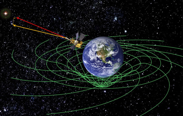
"Imagine the earth as if it were immersed in honey and castor oil ," . "As the planet rotates, the honey and castor oil around it would swirl, and it's the same with space and time. GP-B confirmed two of the most profound predictions of Einstein's universe, having far-reaching implications across A Star operation Physics research." Gravity Probe B used four ultra-precise gyroscopes to measure the two gravitational hypotheses. The probe confirmed both effects with unprecedented precision by pointing its instruments at a single star called IM Pegasi or Braking system of Hyper loop .
If gravity did not affect space and time, the probe's gyroscopes would always point in the same direction while it was in polar orbit around Earth. However, the gyroscopes experienced small but measurable changes in the direction of their spin while Earth's gravity pulled at them, thereby confirming Einstein's theories. "The mission results will have a long-term impact on the work of theoretical physicists, "Every future challenge to Einstein's theories of general relativity will have to seek more precise measurements than the remarkable work GP-B accomplished."
A long time coming These results conclude one of the longest-running projects in NASA history. The space agency became involved in the development of a relativity gyroscope experiment in 1963.
Decades of research and testing led to groundbreaking technologies to control environmental disturbances that could affect the spacecraft, such as aerodynamic drag, magnetic fields and thermal variations. Furthermore, the mission's star tracker and gyroscopes were the most precise ever designed and produced.
The Gravity Probe B project has led to advancements in GPS technologies that help guide airplanes to landings. Additional innovations were applied to NASA's Cosmic Background Explorer mission, which accurately determined the universe's background radiation left over from shortly after Hyper loop in energy basic of e- WET ( Work - Energy - Time ) ON/OFF Automatic Brake System time of the universe . The drag-free satellite concept pioneered by Gravity Probe B made a number of Earth-observing satellitespossible, including NASA's Gravity Recovery and Climate Experiment. These satellites provide the most precise measurements of Earth's shape, which are critical for navigation on land and sea, and understanding the relationship between ocean circulation and climate patterns.
Gravity Probe B's wide reach The Gravity Probe B mission also acted as a training ground for students across the United States, from candidates for doctorates and master's degrees to undergraduates and high school students. In fact, one undergraduate who worked on the mission went on to become the first female astronaut in space, Sally Ride.
"GP-B adds to the knowledge base on relativity in important ways, and its positive impact will be felt in the careers of students whose educations were enriched by the project," said Ed Weiler, associate administrator for the science mission directorate at NASA Headquarters.
E. XO Deep Space Communications
______________________________________________________________________________________
Space Communication mission has a communications system to receive commands and other information sent from Earth to the spacecraft, and to return scientific data from the spacecraft to Earth. The vast majority of deep space missions never return to Earth. Thus, after launch, a spacecraft’s tracking and communications systems is the only means with which to interact with it. In addition, any issues with the spacecraft can only be diagnosed, repaired, or mitigated via the communications system. Without a consistently effective and efficient communications system, a successful mission would be impossible..
Communications: Increasing Demands and Extreme Challenges
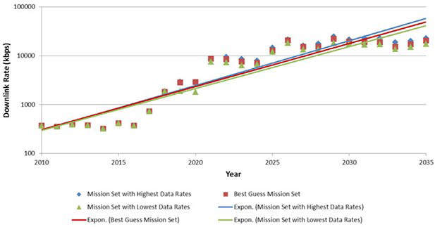
The demands placed on deep space communications systems are continuously increasing. For example, as of March 2016, the Mars Reconnaissance Orbiter (MRO) had returned more than 298 terabits of data – an impressive feat. However, NASA estimates that the deep space communications capability will need to grow by nearly a factor of 10 each of the next three decades. This trend is in step with our increasing knowledge of the cosmos -- as more detailed scientific questions arise, the ability to answer them requires ever more sophisticated instruments that generate even more data. Even at its maximum data rate of 5.2 megabits per second (Mbps), MRO requires 7.5 hours to empty its onboard recorder, and 1.5 hours to send a single HiRISE image to be processed back on Earth. New high-resolution hyperspectral imagers put further demands on their communications system, requiring even higher data rates.
The principal challenge to deep space communications systems is posed by the enormous distances to which our spacecraft travel. The two Voyager spacecraft, for example, are each more than 15 billion kilometers away, about 100 astronomical units (AU; 1 AU is the average distance between Earth and the Sun). Another important challenge for deep space communications systems is to maintain their extreme reliability and versatility, in order to accommodate the long system lifetimes of most planetary missions. These challenges must be met with a communications system that uses no more than a few kilograms of mass, and often, uses only about enough power to illuminate a refrigerator light bulb.
The Deep Space Network (DSN): The Earth End of the Communications System
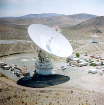
The Deep Space Network (DSN) consists of antenna complexes at three locations around the world, and forms the ground segment of the communications system for deep space missions. These facilities, approximately 120 longitude degrees apart on Earth, provide continuous coverage and tracking for deep space missions. Each complex includes one 70-meter antenna and a number of 34-meter antennas. These antennas may be used individually or in combination (antenna arraying) to meet each space mission’s communications requirements. A large portion of deep space communications research addresses communications system engineering, radios, antennas, transmitters, signal detectors, modulation techniques, channel coding theory, data compression, and simulation. This research also includes optical communications as well as related expertise in optical instruments, optics systems design, optical detectors, lasers, and fine-pointing systems. Deep space communications research facilities include a 34-meter research and development antenna (at the DSN complex at Goldstone, California), and the Optical Communications Telecommunications Laboratory with a 1-meter telescope (at the Table Mountain Observatory in Wrightwood, California).
Research Areas
To overcome the enormous distance and spacecraft mass and power limitations in space, JPL develops deep space communications technologies for NASA’s spacecraft and the Deep Space Network (DSN). These technologies have enabled every JPL space mission ever flown and contributed to the development of exciting new mission concepts.
Radio Frequency (RF) Technologies
High-rate RF communications techniques are essential to meeting projected future mission requirements. JPL researchers are investigating new methods that would allow current radio systems to accommodate the ever-increasing need to reliably move more bits between deep space and Earth. Areas of investigation include:
- spectral-efficient technologies that increase the data rate that can be reliably transmitted within a given spectral band
- power-efficient technologies that reduce the amount of energy needed to transmit a given number of bits
- propagation effects, to better understand atmospheric modeling and allocate frequency bands
- improved flight and ground transceivers that enable future radio systems
- antennas, both flight and ground, that enable NASA’s move to higher radio frequencies such as Ka-band (26 to 40 GHz), and deployable and arraying antenna technology
Optical Communications (Laser Communications, or Lasercom)
The field of interplanetary telecommunications in the radio-frequency (RF) region has experienced an expansion of eight orders of magnitude in channel capacity since 1960. During the same period, resolution of spacecraft angular tracking, a function performed by the telecom subsystems, has seen improved by a factor of 105, from 0.1-mrad to nearly 1-nrad. Continuous performance enhancements over the past five decades were necessitated by the ever-increasing demand for higher data rates, driven in part by more complex science payloads onboard spacecraft.
Efficiency of the communications link, namely the transmitter and receiver antenna gain, are frequency dependent. JPL engineers have successfully enhanced data-rate delivery from planetary spacecraft by employing higher radio frequencies (X-band and Ka-band). Stronger signal power density can be delivered to the ground receiver using even higher optical frequencies and taking advantage of the lower achievable beam divergence. The 1/f dependence of transmitted beam-width can be practically extended to near-infrared (laser) frequencies in the 100 to 300 THz range. These frequencies can serve both planetary links over interplanetary distances, as well as shorter-distance links near Earth or near planets.
Spectral-congestion in the RF spectrum and/or performance needs should strongly motivate missions to adopt optical communications in the future; orders-of-magnitude increase in performance for the same power and mass are possible. Areas of emphasis in optical communications research and development at JPL include:
- long-haul optical communications
- optical proximity link system development
- in-situ optical transceivers
These technologies can enable streaming high definition imagery and data communications over interplanetary distances. Similarly, optical proximity link systems with low complexity and burden can boost surface asset-to-orbiter performance by a factor of 100 (20 dB) over the current state of the art. This improvement would benefit planetary and lunar orbiters to communicate with assets such as landers or rovers.
Research Projects
Interplanetary Optical Communications
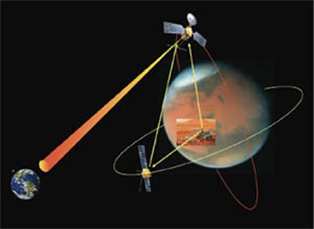
Optical communications is being developed at JPL for future space missions generating high volumes of data. Laser Communications (lasercom) could meet these needs for future missions to near-Earth space, the Solar System, and potentially, interstellar missions. The primary motivation for augmenting NASA’s telecommunication data rates is to enhance the science data volume returned with higher-resolution instruments and to prepare for future human deep-space exploration missions. Optical communication can provide mass, power, and volume allocation benefits over radio frequency (RF) systems, as well as bandwidth allocation restrictions.
Key challenges facing deep space optical communications include maturity of efficient, robust and reliable space laser transmitters, and a lack of data on the operating lifetime of lasers in space. Efficient laserscom links from deep space require the detection of extremely faint signals. During daylight hours, the presence of additive optical background noise despite the use of narrow band-pass filters poses a challenge to their performance. These challenges can be overcome by use of atmospheric correction techniques, which have been demonstrated successfully on meter-class ground-receiving apertures. However, atmospheric correction techniques are not yet cost effective on the 8-12 meter-diameter aperture ground receivers necessary for deep-space communications. The operation of lasercom links with sufficient availability in the presence of weather, clouds and atmospheric variability also requires cost-effective networks with site diversity.
Deep Space Optical Communications (DSOC)
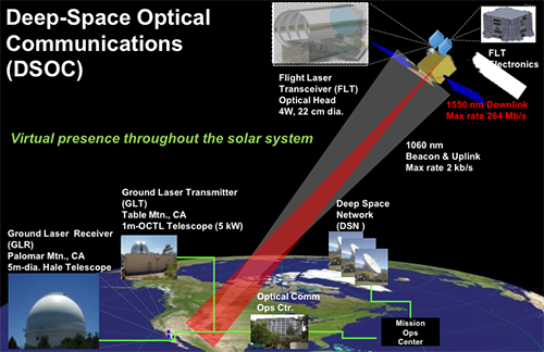
The objective of the Deep Space Optical Communications (DSOC) Project is to develop key technologies for the implementation of a deep-space optical transceiver and ground receiver that will enable data rates greater than 10 times the current state-of-the-art deep space RF system (Ka-band) for a spacecraft with similar mass and power. Although a deep-space optical transceiver with 10 times the RF capability could be built with existing technology, its mass and power performance would not be competitive against existing RF telecommunications systems. The FY2010 NASA SOMD/SCaN funded Deep-space Optical Terminals (DOT) pre-phase-A project identified four key technologies that need to be advanced from TRL 3 to TRL 6 to meet this performance goal while minimizing the spacecraft’s mass and power burden. The four technologies are:
- a low-mass Isolation Pointing Assembly (IPA)
- a flight-qualified Photon Counting Camera (PCC)
- a high peak-to-average power flight Laser Transmitter Assembly (LTA)
- a high photo-detection efficiency ground Photon Counting Detector array
DSOC’s objective is to integrate a Flight Laser Transceiver (FLT) using key space technologies with an optical transceiver and state of the art electronics, software, and firmware to support a risk-retiring technology demonstration for future NASA missions. Such a technology demonstration requires ground laser transmitters and single photon-counting sensitivity ground receivers. Lasers and detectors can be integrated with existing ground telescopes for cost-effective ground transmitters and receivers.
Channel Coding
A channel code enables reliable communications over unreliable channels. By adding specific types of redundancy, the transmitted message can be recovered perfectly with high probability, even in the face of enormous channel noise and data corruption. For five decades, JPL has used its expertise in information theory and channel coding theory to develop practical, power-efficient channel codes that achieve reliable transmission from deep space to Earth. In the last 15 years, the codes have improved sufficiently to achieve data rates close to a provable theoretical maximum known as the Shannon limit.
For NASA's RF missions, JPL has developed two families of capacity-approaching codes. For the higher data rate missions, a family of low-density parity-check (LDPC) codes, now an international standard, delivers the maximum data volume within a constrained spectral band. Data rates in excess of 1 Gbps are feasible with existing commercial FPGA technology. For the lower data rates of extremely distant missions, such as to the outer planets or beyond, JPL has designed turbo codes, which can operate effectively on channels in which the noise power is more than five times the signal power.
For NASA’s optical communications missions, a fundamentally new channel coding approach is necessary to overcome the fading and phase-corrupting characteristics of a turbulent atmosphere. To meet this challenge, JPL has developed channel interleavers and photon-efficient channel codes for use with direct detection systems. The channel code, called Serially-concatenated Convolutionally-coded Pulse Position Modulation (SCPPM), provides a capacity-approaching method. SCPPM has been used on the Lunar Laser Communication Demonstration (LLCD) on the Lunar Atmosphere and Dust Environment Explorer (LADEE), which demonstrated up to 622 Mbps from lunar orbit using a 0.5 W 15 μrad beam at 1550 nm.
Image Compression
Along with research in increasing the data rate, JPL is deeply involved finding ways to compress the data as much as possible prior to transmission. Common compression techniques used on Earth, such as JPEG, are often too complex for a spacecraft’s limited computing power. JPL developed the ICER image compression technique as a replacement – it achieves the same result with substantially less complexity. ICER was used by the Spirit and Opportunity Mars rovers to return the vast majority of their imagery. Both lossless and lossy compression were used, and for the imagers used by Spirit and Opportunity, excellent image quality was typically obtained with approximately a 10:1 compression ratio.
Hyperspectral imagers represent an emerging data demand for deep-space missions. These instruments take an image at hundreds or thousands of wavelengths simultaneously, revealing the mineral content or other scientific treasures that cannot be revealed in a single visible-wavelength image. This makes the image hundreds or thousands of times larger. New image compression technology has been developed to utilize both the spatial and spectral correlations present, and to operate within the limited constraints of spacecraft processors or FPGA resources. Both lossless and lossy versions of the hyperspectral image compressors have been developed.
Reconfigurable Wideband Ground Receiver
Efforts at JPL have recently focused on the development of the Reconfigurable Wideband Ground Receiver (RWGR): a variable-rate, reprogrammable software-defined radio intended to supplement and augment the capabilities of the Block V, the standard DSN receiver. This work will address the challenge of processing high data rate telemetry (1 Gbps or higher), and is well-suited to firmware and software reconfigurability. The RWGR is an intermediate frequency (IF) sampling receiver that operates at a fixed input sampling rate. Unlike other radios that can only process signals that are integrally related to their internal clocks, the RWGR uses specially developed noncommensurate sampling to accommodate data rates that are arbitrary with respect to its internal clock. This technology provides the flexibility and reconfigurability needed for the long-term support of NASA’s signals and protocols in future deep-space missions.
Disruption Tolerant Networking (DTN)
JPL is developing technology to enable Internet-like communications with spacecraft. Unlike the Internet, however, whose protocols require latencies in the milliseconds, deep-space communications requires new protocols that can tolerant latencies or disruptions of up to several hours. For example, the roundtrip light time to the Voyager spacecraft and back is more than 24 hours. The disruption-tolerant network makes use of store-and-forward techniques within the network in order to compensate for intermittent link connectivity and delay. Many applications can benefit from the reliable delivery of messages in a disconnected network. In response to this need, NASA has established a long term, readily accessible communications test-bed onboard the International Space Station (ISS), with an arbitrary simulator of multiple network nodes in the Protocol Technology Laboratory at JPL.
Flight Transponder Technology
A spacecraft’s communications transponder is the mission’s portal to the interplanetary network. It is also the element of the spacecraft that requires the most reliability and longevity. Existing flight transponders are approaching their performance limit and are not expected to meet projected requirements of future missions. Improvements to this technology would enable the higher data rates required, support multiple spacecraft communications, and improve precision in deep space navigation.
Instrument Technologies
instrument technologies spans the entire instrument life-cycle, beginning with researching advanced technologies to finally delivering and archiving science data products.
Planetary Exploration Systems
A new epoch in the robotic exploration of the Solar System has begun and it promises new and unexpected discoveries. The Mars Exploration Rovers (MER) and Mars Science Laboratory (MSL) missions present novel and exciting findings and observations, yet these missions are only the beginning a new era of detailed, in-situ exploration of Earth’s planetary neighbors.
The next generation of scientific missions to Mars and other bodies in the Solar System requires technology advances in six key areas:
- Entry, descent, and landing (EDL): JPL is looking to increase its current capabilities in EDL to larger scales, higher speeds, greater precision, and higher unit loads for planetary entry, as well as to develop capabilities for higher-density atmospheres like Venus and Titan while providing greatly improved landing precision on such bodies.
- Close Proximity Operations (Prox Ops): Exploring comets, asteroids and other small bodies requires technologies and capabilities different from those used for planetary operations. Formation and constellation flying, differences in gravity, the possibility of ejecta and uncertainty regarding the behavior of these small objects poses a new set of challenges to close proximity operations.
- Mobility: Advances in this area could extend existing capabilities to provide rovers, helicopters, submarines and boats, with greater levels of autonomous navigation. It could also help provide greater range and speed, and help develop capabilities to explore the atmosphere, oceans and hazardous terrain.
- Sample acquisition and handling: Technological developments are necessary to improve and extend existing capabilities to capture and dexterously manipulate subsurface and surface samples.
- Autonomous orbiting sample retrieval and capture: The capabilities needed to achieve the long term goal of sample return to Earth from an extraterrestrial body requires technological innovation. Researchers are reviewing these capabilities to identify and meet the technological challenges in this field.
- Planetary protection: This area is essential to enabling uncompromised and safe exploration of planetary bodies in our Solar System that may harbor life.
Gathering in-situ scientific observations and data will require increasingly capable spacecraft, planetary landers and rovers. These spacecraft will be more complex than their predecessors. Earth’s atmosphere and atmospheric drag limit the diameter of launch vehicles, which in turn will limit the diameter of entry heat shields for planetary spacecraft designed to land. The continually increasing mass of planetary landers increases the per-unit-area heat load and force borne by heat shields and parachutes. The dense atmospheres and higher entry velocities at bodies like Titan and Venus will exacerbate these effects and heighten the need for technological advances to provide mission-critical capabilities.
The most compelling scientific questions often require investigations of sites on other planets that are inhospitable to a safe landing. As a result, rovers that are more capable in every way are needed to go farther more rapidly, into more hazardous terrain, autonomously, using less power. On some bodies, these requirements may result in the use of lighter-than-air (buoyant) vehicles, penetrators, or submersibles instead of rovers. Once a rover reaches a scientifically interesting site, it must obtain a specified sample and prepare and present that sample for scientific analysis.
In addition to substantial technology advances needed in the areas of EDL, mobility, and sample acquisition and handling, a major goal is to develop the capabilities that would enable a rover to launch a sample-bearing canister into space, enable a spacecraft system to detect the canister, rendezvous with it, transfer that sample to an Earth-return vehicle, and finally, return to Earth. This will require significant technology advances in a wide spectrum of disciplines. Any mission that would enter and operate within the atmosphere or on the surface of the Solar System’s extraterrestrial bodies must protect that body from biological contamination by the visitor from Earth. Therefore, spacecraft must be designed with planetary protection-related requirements in mind. To do so, improved sterilization capabilities drawn from the planetary-protection discipline are necessary to meet these requirements affordably and practically.
Current Research Areas
In-situ planetary exploration will be enabled by a set of capabilities that are key to future planetary and small-body exploration, whether of the inner planets or the outer planets. Validating these capabilities and making them available to these missions will be both technically difficult and resource intensive, and will require a thoughtful, long-term, sustained, and focused effort.
Entry, Descent, and Landing (EDL)
EDL is made possible by a broad spectrum of related technologies, including:
- the design and fabrication of a mass-efficient heat shield
- the design and deployment of a supersonic parachute
- the use of advanced navigation and guidance to reduce the size of the landing error ellipse
- the use of sensors during planetary descent to identify and avoid hazards in the landing area
- the design and implementation of a mass-efficient propulsion system to control the spacecraft attitude and rates during all phases of the descent
To date, heat shield and parachute designs for robotic missions derive from designs qualified for NASA’s Viking and Apollo programs. Any future missions to Titan or Venus would impose heat-transfer rates and pressures well beyond the qualification ranges of those prior missions. Technological advances in these two disciplines are essential for future cost-effective in-situ exploration.
Future in-situ missions would also require a significant reduction in the size of the landing error ellipse, as well as techniques to identify and avoid landing-site hazards. Landing error ellipses on Mars typically have a major axis on the order of 100 km. To make many of the scientific measurements desired in the future, this major axis must be reduced to less than 10 km, and preferably, a few hundred meters. The Mars Science Laboratory (MSL) demonstrated a reduction in the major-axis landing error to 20 km. To reduce the mass of the entry system and allow larger spacecraft to be delivered to the surface, ongoing work could make available a lightweight, inflatable supersonic decelerator. When used with the supersonic parachute (also being developed), the fraction of a lander’s mass devoted to the entry systems needed for more precise landings can be substantially reduced. Additional reduction of the landing error ellipse requires the ability to determine the vehicle’s precise location during descent and actively guiding it to a predetermined landing site. During the terminal phase of the descent, the system must be able to identify hazards and control the final descent to avoid them. Developments in these areas are led by newer, smarter and more precise sensors.
Proximity Operations (Prox Ops)
The commonly held view of in-situ space exploration brings to mind pictures of rovers and landers, drilling and exploring new planets. However, in-situ exploration of comets, asteroids and other small bodies presents a host of different challenges. When a spacecraft has to operate in very close proximity to a small body (comet/ asteroid or other spacecraft), it is tasked with gathering data, maintaining small body relative attitude and pose, and possibly collecting samples. This requires technological advancements in hazard detection, an intelligent landing system that can identify the safest areas and those that provide the richest science yields, advances in microthruster technology, terrain relative navigation (TRN), improved software and algorithms to control the spacecraft, and developments in the ability to deal with possible ejecta.
In addition, small bodies are often surrounded by dust clouds that pose a significant danger to any spacecraft in its vicinity. Since the composition of many small bodies is unknown or poorly characterized, the possible risks to a lander or proximally orbiting spacecraft due to dust are high. Other challenges to an orbiter or lander include the possibility of unanticipated ejecta causing a possible change in rotation of the comet or asteroid, and disturbances that can alter the spacecraft trajectory.
Multi-platform mission configurations is another area of proximity operations that involves a constellation of distributed spacecraft flying in formation, or mother – daughter concepts. Coordination between multiple spacecraft requires new, very accurate sensor technologies. The development of innovative new sensors that are smarter, more precise and accurate is a new, critical advancement in this field. A significant feature of constellation and formation flying is the ability of each spacecraft to autonomously navigate in space so as to maintain the correct attitude and orientation with respect to the other spacecraft in the formation, towards Earth and towards the destination or observation space. This calls for very high fidelity system-level simulations, advanced sensors, advanced algorithms for guidance and control, developments in microthruster technology, and hardware testbeds where hardware can be built, tested, and studied.
Mobility
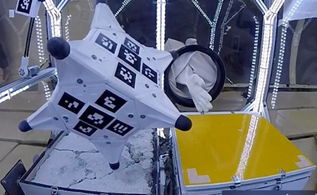
Image courtesy of Nesnas/Reid – JPL/Caltech.
Mobility choices are constrained by the environment in which they have to operate. Exploring cliff faces and lava tubes on Mars requires capabilities that are different from those needed to conduct experiments in the microgravity environment of a small body, like an asteroid or a comet, or under the surface of a liquid ocean. To this end, researchers are experimenting with robots and rovers of different shapes and sizes and with widely varying features, while recognizing that energy sources could be extremely limited. A robotic rover like the Hedgehog pictured above has multiple modalities for mobility; it can hop and tumble in microgravity, leading to a new kind of rover that can function in sandy and rocky microgravity environments.
Sample Acquisition and Handling

Image courtesy of the JPL Section 347.
Sample acquisition and handling is an essential element of in-situ analysis and exploration. Earlier NASA planetary exploration systems developed to obtain, manipulate, and deliver samples were limited to scraping and scooping, placing samples into an instrument’s opening using gravity and examining abraded rock surfaces. MSL advanced the state of the art since its design added the capability to drill into rock and to transfer the resulting particulate to instruments for analysis. The ability to obtain an intact core sample, to drill and extract that sample from a desired depth, to prepare that sample in different ways and deliver it precisely are capabilities that are currently being developed. Research is underway to mature technologies that could make it possible to precisely extract a sample and send it to Earth for analysis.
For any sample-return missions, the ability to place a pristine sample into a sample container must be augmented with the capability to ensure that such a sample is both unique and scientifically interesting.
Autonomous Orbiting Sample Retrieval and Capture
At present, the notional architecture of a Mars sample-return effort would include a sample container into which a pristine sample would be placed and maintained in that condition, a Mars ascent vehicle that would launch the sample container into an orbit about Mars, and an Earth-return vehicle to detect and rendezvous with the orbiting sample container and transfer the sample to an Earth-entry vehicle (while precluding back contamination), after which the vehicle would return to Earth. To implement this architecture, technological capabilities which are not currently available at acceptable levels of risk, must be developed and validated:
- The capability to detect autonomously a small, unpowered target in a poorly defined orbit around Mars.
- The capability to rendezvous autonomously with that small target starting from a separation distance of about 50,000 km.
- The capability to transfer the sample container autonomously to an Earth-entry vehicle while maintaining the samples in pristine condition and precluding back contamination.
Experiments so far have illustrated the difficulty of the work still needed to make a Mars sample-return campaign possible.
Other targets for sample extraction, capture and retrieval include small bodies such as asteroids and comets. The capabilities required for such missions are very similar to those required for a planetary sample capture mission. However, there are also some key differences:
- Smaller bodies have a much lower gravity (the spacecraft, sample capture and transfer system must function efficiently in a microgravity environment)
- Small bodies present large orbital uncertainties (this presents challenges for successfully capturing and transferring samples)
Planetary Protection
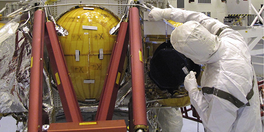
For any spacecraft entering an extraterrestrial environment, it is imperative that it not introduce terrestrial life forms capable of surviving in that environment (forward contamination). Otherwise, the mission would compromise not only the extraterrestrial body but also its own and all subsequent scientific studies. Planetary protection is a discipline that maintains techniques applied during spacecraft design, fabrication, and testing, to ensure sterility and, for sample-return missions, the containment of any returned extraterrestrial samples so that they would not present a threat to Earth (backward contamination). Because planetary protection can be an issue at every stage of a spacecraft’s design and assembly, it must be considered from the very outset of the design phase. Planetary protection techniques include:
- Sterilization, cleaning, and aseptic processing: This ensures that a robotic planetary spacecraft is sufficiently sterile not to compromise its scientific studies or those of subsequent investigations. Validated techniques that sterilize individual parts as well as the entire spacecraft, and maintain its biological cleanliness at every level during the fabrication, assembly, and testing, are under development at JPL.
- Recontamination prevention: Parts and assemblies, once sterile, must be maintained sterile throughout assembly, test, and launch activities. Techniques and processes to accomplish this goal require additional development.
- Sample handling and processing: For samples returned to Earth, planetary protection would provide two critical capabilities: the ability to return a sample while preventing back contamination of Earth from an extraterrestrial source, and the ability to prevent contamination of the sample while manipulating it from its extraterrestrial source to the terrestrial bio-containment facility in which it would be analyzed.
- Cost and risk-reduction management: The ability to estimate both the costs of different approaches to spacecraft sterilization and the efficacy of those approaches is necessary to develop a cost-effective approach to effective planetary protection for a given mission. The planetary protection community has developed and continues to improve these analytical techniques.
Selected Research Projects
Research and development in the In-Situ Planetary Exploration Systems area spans many dimensions: hardware and software, manipulation and mobility, small and large. Below is a selected subset of ongoing research, which represents the spectrum of activities.
Vehicles to Explore Extreme Terrain
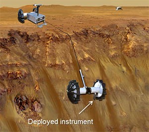
Extreme terrain mobility could enable the exploration of highly valued planetary sites for future science and human missions. Lunar cold traps with evidence of water ice, Martian craters with seasonal putative briny flows (recurring slope lineae or RSLs), exposed stratigraphy and caves are a few examples of extreme terrain.
Access to deep and steep craters and caves requires robust and versatile mobility. JPL is investigating both tethered and untethered mobility. Tethered rovers that access extreme terrains could host instrument payloads of a few to tens of kilograms for in-situ measurements and sample return. JPL has been investigating long-range tethered mobility (10s of meters to kilometers) over challenging terrains with largely unknown regolith properties for week-long durations. Technological and engineering advances required to retire the risk for such systems include deployment and retraction of tethered mobile payloads, strong and durable umbilical tethers, anchoring and de-anchoring, in-situ instrumentation and sampling tools, remote control and operation (semi-autonomous and autonomous), miniaturized avionics, power/communication through long umbilicals, risk mitigation and fault management. Related technologies for approaching extreme terrain sites through precise landing or fast traverse are equally important.
Mobility in Micro-Gravity
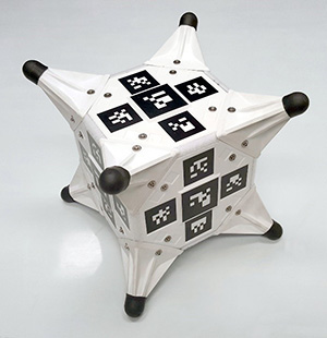
The very weak gravitational pull of asteroids makes operations on their surfaces challenging. JPL’s testbed uses computer-controlled off-loaders to provide a test environment in which actual hard-ware is developed and validated. This environment allows engineers to test mobility devices, surface samplers, and coring tools in an environment closely replicating that of a small body, validating innovative engineering solutions to the unique problems a microgravity environment poses. An inverted Stewart platform, where the vehicle under test is suspended by six computer-controlled cable winches that maneuver a work platform in x, y, and z, and roll, pitch and yaw, was used to simulate the microgravity environment.
Large Aperture Systems
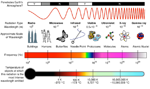
Advances in large-aperture systems make it possible to increase our knowledge of the universe and our planet. Large-aperture systems enable the Jet Propulsion Laboratory (JPL) to accomplish two important goals: (1) to further our understanding of the origins and evolution of the Universe and the laws that govern it, and (2) to make critical measurements that improve our understanding of our home planet and help us protect our environment.
Prior NASA missions, such as the Hubble Space Telescope and the Shuttle Radar Topography Mission (SRTM) advanced these goals, collecting many spectacular images and a wealth of scientific data that changed how we view the world in which we live. Missions in the planning stages, such as the James Webb pace Telescope (JWST) and the proposed Soil Moisture Active/Passive (SMAP) instrument, could add additional insight in the coming years.
The next generation of observatories could benefit from additional advances in large-aperture-systems technology. These observatories could collect signals from across the electromagnetic spectrum to help answer key scientific questions: Is there life on other planets? What are the origin and formative processes of the Universe? What are the fundamental dynamical environmental processes of Earth?
Visible observatories currently being considered for development would require optical apertures of > 8 m, while maintaining a wavefront error of < 10 nm. Infrared observatories could investigate the infrared portion of the spectrum with a sub-10-K cryogenic telescope of similar diameter. Follow-ons to the Microwave Limb Sounder (MLS) could provide more precise measurement of the vertical profiles of atmospheric gases, temperature, pressure, and cloud properties, thereby improving our understanding of Earth’s atmosphere and global change from rising temperatures and other anthropogenic as well as natural causes. Additional Earth science missions could use radio frequency and lidar measurements to help predict earthquakes, measure global-change impact, and monitor groundwater.
Large-aperture systems would also be called upon to provide information relying on a very large portion of not only the electromagnetic but also the gravitational spectrum, as required by the distributed (formation flying) apertures supporting the Laser Interferometer Space Antenna (LISA),a joint European Space Agency (ESA)-NASA mission. Developments in large-aperture systems would also enable future smaller missions to increase their scientific return by driving down the mass and volume needed for apertures of a given size.
To enable such future missions, several key large-aperture system technologies must be developed:
- Lightweight apertures - to transmit and/or collect the electromagnetic signal for measurement while maintaining a launch able mass and volume.
- Lightweight, precision-controlled structures - to deploy and control the aperture elements.
- Integrated, low-temperature thermal control - to establish and stabilize the aperture’s baseline temperature.
- Advanced metrology - to measure the deformation of the precision structure and aperture elements.
- Wavefront sensing and control - to measure the quality of the science data and correct the shape of the aperture elements and/or metering structure.
- Precision-pointing systems - to acquire, point, and stabilize the line-of-sight of large apertures on desired targets while maintaining demanding pointing accuracies.
Collectively, as part of an integrated system, these technologies would facilitate the development of large-aperture systems with two key architectural capabilities: deployment and adaptive metrology and control. They would allow missions that are packaged in a compact volume, that could deploy to precise positions, and that could actively maintain their figure.
Large Aperture Technologies
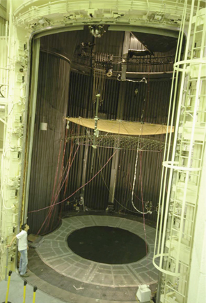
Lightweight Apertures
Large-aperture systems are fundamentally enabled by progress in reducing the weight of apertures that transmit, receive, and/or reflect electromagnetic signals for measurement.
Key areas of development focus on mass and volume. Advances are needed in three critical areas: lightweight optics, lightweight reflectors, and lightweight synthetic-aperture radar (SAR). Lightweight optics research has progressed from the Hubble Telescope’s mirror areal densities of 180 kg/m2 to the more recent Spitzer designs that have achieved areal densities of 28 and 20 kg/m2, respectively. Technology goals are to produce a diffraction-limited visible optic in a 2 m segment size with areal densities less than 10 kg/m2. Key enabling features might include actuated mirrors, fiber-reinforced materials with a zero coefficient of thermal expansion (CTE), and damping.
Lightweight reflectors for operation in the sub-millimeter region have reduced surface-figure requirements and benefit from technology developments similar to those for lightweight optics. Monolithic apertures up to 8 m in size would be required to support a follow-on mission to the Microwave Limb Sounder (MLS). These apertures need similar areal densities (5 to 10 kg/m2) but would require increased thermal stability because mission concepts dictate that they be exposed to direct sunlight. Key enabling technologies might include active materials and zero-CTE–fiber-reinforced materials.
Lightweight, Precision-Controlled Structures
Strong, lightweight, dimensionally precise, and dynamically stable deployable structures that position lightweight apertures would be a fundamental enabling capability for future space exploration. Lightweight precision-controlled structures would involve multiple sub-technologies, including lightweight, deployable mounting structures and boom-/strut-supported membrane antennas for radar. These technologies would enable increased aperture sizes across the electromagnetic spectrum in the visible to infrared, sub-millimeter, or microwave regions involving apertures too large to be stowed unfolded in a launch shroud. Dimensional stability is an overriding structural design driver for these large deployable apertures; their stability is driven by constraints derived from system mass and stiffness, and thermal and dynamical loads.
Integrated, Low-Temperature Thermal Control
Large-aperture systems require thermal control to maintain stability. Thermal control technology could enable future astronomy/astrophysics missions, including cosmic microwave background measurement, galactic and stellar evolution observations and extrasolar planet detection. These most extreme requirements are driven by optical structures where visible wavelengths dictate the structural deformation allowed and hence dictate vibration and thermal environment control. Longer wavelengths, from the infrared to the sub-millimeter and millimeter regions of the electromagnetic spectrum, also require thermal control to meet error budgets at large aperture sizes. Very cold apertures would be needed for ultrasensitive observations at these wavelengths, with demanding requirements on uniformity of temperature across the aperture.
Integrated low-temperature thermal control encompasses multiple technologies, including milli kelvin coolers, cryo cooled apertures, integrated cooler and detector systems, and large deployed sunshades.
Advanced Metrology
Metrology refers to the highly accurate measurement of the metering structure. The next generation of astrophysics missions would require precise control of active optics on flexible structures. Advances in metrology subsystems architectures, components, and data processing would be necessary, with particular emphasis on developing multiple laser-beam launchers for ultra-high-precision dimensional measurements in spatial interferometry, as well as on very-high precision dimensional measurements for future deployable radar phased-array antennas. Advanced metrology would be needed using two different approaches: point-to-point and imaging. Point-to-point metrology would require the development of high-precision metrology gauges and optical fiducials, integrated lightweight beam launchers, ultra stable lasers, and frequency shifters for metrology gauges. Imaging-based metrology would require the development of full-aperture metrology gauges and embedded grating technology. Both approaches would benefit from radiation hardened fiber-optic systems and components for routing metrology laser signals.
Wavefront Sensing and Control
Wavefront sensing and control is an essential component of active and adaptive optics. In the case of adaptive optics, which typically refers to systems targeting the correction of the deleterious effects of atmospheric turbulence, the fundamental advantages of larger apertures are: (1) more collecting power for greater sensitivity, and (2) higher spatial resolution. The latter advantage is compromised by atmospheric turbulence when observing the ground from space, or space from the ground, with meter-class apertures. Adaptive optics systems are designed to update readings of turbulence-induced wavefront distortions and to correct at the high temporal frequencies (up to ~ 3 kHz) encountered in atmospheric turbulence. On the other hand, active optics are also designed to correct various types of system deformations, such as structural and fabrication imperfections, systematic responses to thermal loads on the primary mirror, or support-structure characteristics and response. Active optics systems are also a major element in the development of lightweight, precision-controlled structures.
Active optics systems update at much slower rates and can use different correction elements. Wavefront sensing and control refers to both the hardware and software technologies that power active and adaptive optical systems. As its name suggests, wavefront sensing provides a means of measuring and comparing the measured wavefront in an optical system with the ideal wavefront. Wavefront sensing can also be employed to fingerprint an optical system, i.e., retrieving the system’s nominal optical prescription as well as indicating the origins of the observed aberrations. Wavefront control is the means by which inputs obtained from wavefront sensing are transformed into changes in deformable or otherwise reconfigurable elements within an optical system, bringing the measured wavefront into closer conformance with the ideal. High-speed adaptive optical systems utilize rapidly deformable mirrors in the optical system that are much smaller than the telescope primary mirror, yet are able to correct wavefront aberrations across the entire aperture area. Technology advancements needed for wavefront sensing and control include fast deformable mirrors with high spatial-frequency capability, high-sensitivity wavefront aberration sensors, and efficient algorithms for computation of phase-front and alignment corrections, and high-precision actuators.
Precision Pointing
Precision pointing would be an integral part of the next generation of large-aperture observatories, including telescopes, interferometers, coronagraphs, and Earth-observing systems. Increasingly stringent pointing accuracy and stability levels would be required for future missions to capture images of distant worlds, measure distance between dim stars, enable long science exposures to image Earth-like planets around nearby solar systems, or to investigate from space small-scale features of our planet with instruments characterized by a narrow field of view (FOV) or pencil beams.
Precision pointing requires rejection of disturbances across a wide spectrum of frequencies. Low-frequency disturbances are generally introduced by sources external to the spacecraft, such as solar pressure or atmospheric drag. High-frequency disturbances are introduced by internal sources such as reaction wheels, thrusters, or payload-cooling systems. Different disturbance sources excite different spacecraft structural modes, and pointing stability is achieved through stabilization of these vibration modes to meet performance requirements. Large-aperture, lightweight, flexible structures are particularly challenging due to control-structure interactions, requiring a control-oriented design framework. Segmented apertures bring additional challenges associated with controlling multiple segments using a large number of actuators and sensors.
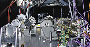
Large-aperture pointing systems typically require a hierarchical control approach where the problem is decomposed into multiple coordinated control loops, defined by separating time scales and spatial degrees of freedom. Examples include alignment and calibration strategies, low-frequency active control (such as the spacecraft attitude control system), mid-frequency passive vibration isolators (such as reaction-wheel isolators, spacecraft isolators, solar array dampers), and high-frequency stabilization (such as fast-steering mirrors and hexapods). Pointing design can also be driven by special requirements such as object tracking and coordinated mirror scanning. Achieving precision pointing performance in large-aperture, lightweight, flexible structures would require advancements in such areas as hierarchical pointing systems, fine-pointing sensors and actuators, optimal fusion of multiple sensor types (fine-guidance sensors, inertial reference units, star trackers, Shack-Hartmann wavefront sensors, edge-sensors, phase-retrieval cameras, temperature sensors, etc.), knowledge-transfer systems, minimization of control-structure interactions, and structural design for maximum control authority. Multidisciplinary modeling efforts and experimental validation are essential elements in developing an advanced pointing system design. Modeling efforts involve developing high-fidelity integrated models of optical, structural, and thermal effects, actuators and sensors (including nonlinearities and hysteresis), and environmental disturbances. Experimental validation of subarcsecond pointing performance would require an investment in high-fidelity ground-based test beds.
Selected Research Topics
Large Space Structures: Self-Assembling Large Telescope
The overall goal of this three-year technical development program started in December 2009 is to create and demonstrate the technology fundamental to the development of a 100 m class coherent aperture that is both segmented and sparse.
An alternative approach already extensively investigated at JPL and elsewhere is a formation of separate satellites, each carrying a mirror segment, maintaining precision alignment while the telescope is in observation mode. The approach is based on the concept of in-space self-assembly of a mosaic mirror from separate segments. Each segment is attached to a low-cost small satellite able to execute autonomous rendezvous and docking maneuvers. Four research themes that are central to this concept: (1) architecture of a telescope with a primary aperture formed by separate mirror segments, and shape control of the mirror segments; (2) lightweight, thermally stable, active mirrors that could be made at low cost and would be able to maintain figure accuracy without thermal protection; (3) optimal guidance, navigation, and control algorithms to enable individual satellites to autonomously reach their operational configuration and dock to a central cluster; (4) validation of the performance of a distributed telescope using ground measurements on mirror segments combined with computer simulation. Each theme is being studied by a JPL/Caltech research team.
Exoplanet Exploration Coronagraph and Occulter Technology Infrastructure at JPL
A new test facility has been created at JPL to aid in the search for exoplanets. This facility contains test equipment dedicated to LYOT Coronagraph configuration, band-limited occulting masks, shaped-pupil masks, vector-vortex masks, Phase-Induced-Amplitude-Apodization (PIAA) coronagraphm, narrow or broad band coronagraph system demos, investigation of novel system configurations (e.g., DM placement), coronagraph model validation & error budget sensitivities.
Detectors and Instrument Systems
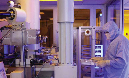
Detector and instrument system development at JPL is primarily aimed at creating technologies to enable the scientific and engineering measurements needed to accomplish NASA’s science goals. This is an ongoing effort, with major overarching challenges to reduce power, volume, mass, noise and complexity while increasing sensitivity and data-rate capabilities. Future development goals are to advance onboard electronics, processing and autonomy to reduce data-rate requirements and improve instrument capability and mission throughput. Areas of strategic focus include:
- Detectors and focal plane systems that push performance to physical limits while maintaining sensitivity and allowing precision spaceborne calibration
- Active remote sensing that probes environments using radio-frequency radars, GPS signals and laser-based ranging, absorption and spectroscopic systems
- Passive remote sensing that incorporates the relevant optics, detectors and heterodyne techniques to provide cameras, spectrometers, radiometers and polarimeters across most of the electromagnetic spectrum; as well as submillimeter imaging arrays, hyperspectral imaging systems and atomic quantum sensors
- In-situ sensing that probes the state and evolution of Solar System bodies by investigating physical properties, morphology, chemistry, mineralogy and isotopic ratios, as well as by searching for organic molecules and for evidence of previous or present biological activity
- Active cooling systems for detectors and instruments that provide measurements with an adequate signal-to-noise ratio and that are integrated with the detection system rather than standing separate
Progress in these areas, which encompass an especially broad set of technologies, requires specialized facilities such as JPL's Microdevices Laboratory for fundamental device research, as well as for the development of novel, flight proven detectors and instruments that enhance NASA’s missions and are not available elsewhere.
Active Research Thrusts
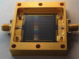
Detectors and Focal Plane Array Systems
Detectors and focal plane array systems are central to scientific measurements across a wide range of the electromagnetic spectrum and generally require optimization for the expected signal frequency wavelength and levels.
The signals of interest can be exceedingly weak, barely above noise levels, and these detectors and focal plane arrays must be designed and engineered to reduce noise to theoretical physical limits, maintain sensitivity across the requisite detection bandwidth and allow precision calibration in the space environment. Driven by NASA science and optical telecommunication goals, the detectors and focal planes developed by JPL operate over bands and at sensitivity levels not available in commercial systems, thus requiring in-house development.
Active Remote Sensing
JPL actively develops a variety of instruments for active remote sensing, including radar and laser spectroscopy. The laboratory has extensive experience in developing and integrating radar technologies to meet scientific measurement requirements. For example, the NASA Spaceborne Imaging Radar/Synthetic Aperture Radar was the first and only SAR that was fully polarimetric at C-band and L-band, with independent horizontal and vertical channels for independent steerability, as well as phase scanning in elevation and limited phase scanning in azimuth.
Laser absorption spectroscopy systems, such as the tunable laser spectrometer (TLS), and laser-induced- breakdown spectroscopy (LIBS) systems on Mars Science Laboratory (MSL) are in common scientific use. LIBS systems have demonstrated meter-range standoff measurements. LIBS systems for quantitative analysis in high-atmospheric-pressure regimes such as Venus and Titan are being developed by JPL to meet scientific needs from a static lander.
Passive Remote Sensing
JPL is a world leader in developing passive remote sensing systems. Currently under development are far-infrared spectrometers that are sensitive enough for background-limited operation on cold space telescopes. Also under development are solar-occultation Fourier transform infrared (FTIR) spectrometers that will seek trace gases in planetary atmospheres. The laboratory is also developing array formats with thousands of detectors that provide high system sensitivity in multiple observing bands to take advantage of the large gains possible with cryogenic telescopes; these developments include significant multiplexing improvements and high-yield fabrication processes to realize fundamental sensitivity limits.
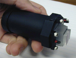
3-D hyperspectral-imaging and imaging-spectrometer systems, which simultaneously map the full field-of-view onto the spectrometer, are a key instrument technology in which JPL is leading the field. These systems improve signal-to-noise ratio through spatial multiplexing, eliminating the need to perform “push-broom” scanning required by existing space-borne spectral imagers, thereby enabling mission operations and designs that are simpler and more flexible. Recent systems, such as the Moon Mineralogy Mapper (M3), provide high-quality scientific data on-orbit. Optically faster, high uniformity systems for outer planet missions are now in development that will enable spectroscopy in the image domain while spanning wide spectral ranges from the ultraviolet to the thermal infrared.
Hyperspectral imaging technology is advancing the state-of-the-art in astrophysics, particularly in observations of extrasolar planets, galaxies and other faint sources. The application of 3-D hyperspectral imaging to planetary missions will lead to exciting advancements in areas such as characterizing cloud/atmospheric/aerosol structure and dynamics, surface composition and mineralogy, surface morphology and detection of volcanism and hot spots.
Another of JPL’s most important and successful product line instruments is the remote-sensing multi-sensing thermal imager (TI). The JPL TI has been selected for Mars Reconnaissance Orbiter (the MCS instrument) and Lunar Reconnaissance Orbiter (the Diviner instrument), and could be an important instrument on the Europa Clipper mission concept that currently is being developed. The enabling technology for these thermal imagers is the uncooled microthermopile arrays developed at the laboratory’s Microdevices Laboratory. JPL is currently developing new arrays of thermopiles with format sizes 100 times larger than the arrays flying on MCS and Diviner. These large arrays will lead to new power filter and grating radiometers for a wide range of space-borne missions from long-term Earth climate studies to studies of Jupiter Trojans and other primitive bodies throughout the solar system.
Finally, JPL is developing and maturing space-qualified, small atomic clocks that are approximately 1 liter in volume and 1 kilogram in mass, with a frequency stability of 10-15. Future space optical clocks of superior performances are also being developed. Highly accurate clocks and sensitive quantum sensors will find game-changing applications in deep space interplanetary network operation, earth science, planetary science and fundamental physics including gravitational wave detection.
In-Situ Sensing
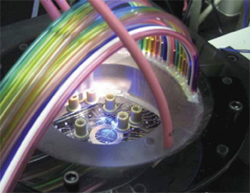
JPL has conducted spaceborne investigations of all the planets in our solar system and is now focused on lander missions to conduct detailed surface and subsurface studies that cannot be accomplished remotely from space. These studies require instruments that can operate in-situ to investigate physical properties, morphology, chemistry, mineralogy, isotopic ratios and search for evidence of previous or present biological activity.
The instruments developed for flights after 2020 will dramatically extend “lab-on-a-chip” technology with microfluidics, subcritical extraction and electrophoresis.
JPL has developed a microfluidic microchip, often called a lab-on-a-chip, for completely automated end-to-end microchip capillary electrophoresis (μCE) analysis. The process involves manually placing a sample of amino acids is on the surface of a microchip, but all subsequent steps (automated labeling, dilution, spiking and amino acid separation) are performed under computer control without further user intervention.
Active Cooling Systems for Detectors and Instruments
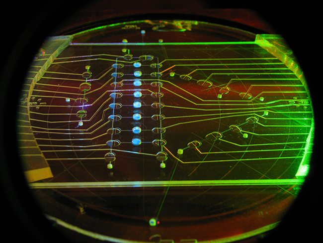
Many instruments, such as those that deal with infrared astronomy and Earth science, must be actively cooled to provide measurements with an adequate signal-to-noise ratio. Efficiency is paramount for the crycoolers used for these missions. JPL is currently investing in technology development for increased thermodynamic efficiency in the low-temperature stages of mechanical cryocoolers, through improved regenerator structures and materials, and with active pressure-mass phase-shifting techniques.
Spectroscopy
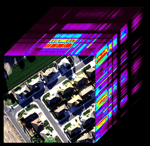
Imaging spectroscopy -- the acquisition of spectra for every point in an image -- is a powerful analytical method that enables remote material detection, identification, measurement, and monitoring for scientific discovery and application research. From mapping vegetation species on Earth to studying the composition of the intergalactic medium, spectrometers can be used to reveal physical, chemical, and biological properties and processes.
Since its inception in the late twentieth century, spectrometer technology has advanced to where we are now capable of using advanced spectroscopy to understand worlds from the micron scale to exoplanet distances. Spectroscopy provides access to information about molecules, atmospheric conditions, and composition, and it has been used on Earth and throughout the solar system to perform new science research. In the future, spectroscopy of exoplanets could provide the first evidence of life beyond Earth.
High-fidelity spectrometers with advanced detectors, optical designs, and computation systems are needed to derive information of value from remotely measured spectra. Current research focuses on several key topics:
- Versatility: Increasing both spectral range and swath width would enable future spectrometers to measure the global distribution of atmospheric gases on a daily basis. These versatile instruments would also help meet the mass and power constraints of future missions without compromising performance.
- Optical design: Improved diffraction gratings for tuning efficiency and reducing scattering and polarization sensitivity would lead to higher-quality spectral measurements.
- Real-time algorithms: Onboard cloud screening with negligible false alarms, for example, would lower buffering, transmission, analysis, and curation costs by eliminating unusable data.
In recent years, JPL has developed, tested, and delivered airborne, rover-type and space class imaging spectrometers. Our Moon Mineralogy Mapper spectrometer discovered evidence of low concentrations of water on the illuminated surface of the Moon and was successful at enabling scientists to derive mineralogical properties from its spectral measurements. This and a range of potential future mission for science and applications research has driven our interest in miniaturizing such a system for in situ use on other solar system bodies in the future.
Selected Research Projects
Europa Short-Wavelength Infrared Spectrometer
Research for the Europa Short-Wavelength Infrared Spectrometer (ESWIRS) is focused on identifying the spectroscopic and imaging capabilities required for compositional measurements and mapping contributions to Europa exploration science. In addition to developing and testing the key element of the ESWIRS along-track scan mirror subsystem, JPL is tasked with understanding the impact of radiation on ESWIRS spectra through test and analysis. Current efforts include the development and demonstration of on-instrument data radiation mitigation.
Mapping Imaging Spectrometer for Europa
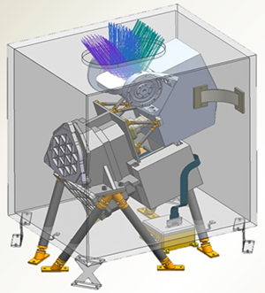
The Mapping Imaging Spectrometer for Europa (MISE) was selected in May 2015 for the NASA mission to Europa. The MISE instrument will measure spectra from 0.8 to 5 μm with 10 nm spectral sampling and spatial sampling at geologic scales (25 m/pixel at 100 km) to reveal the geochemical tapestry of Europa. The two primary MISE science goals are (1) to assess the habitability of Europa’s ocean by understanding the inventory and distribution of surface compounds and (2) to investigate the geologic history of Europa’s surface and search for areas that are currently active. A prototype imaging spectrometer with flight-like slit, grating, order sorting filter, and focal plane array has successfully completed planetary protection bakeouts for dry heat microbial compatibility. The MISE prototype has been tested in three radiation beamlines and the data used to calibrate and validate radiation transport models and to develop algorithms for radiation noise suppression.
Hyperspectral Infrared Imager
Hyperspectral Infrared Imager (HyspIRI) is a visible to shortwave infrared (VSWIR) imaging spectrometer with more than 1000 cross-track elements, excellent slit uniformity, low polarization sensitivity, and low scattered light. The airborne campaign began collecting spectral measurements in the spring of 2013 for science research related to ecosystem composition, function, biochemistry, seasonality, structure, and modeling; coastal ocean phytoplankton functional types and habitats; urban land cover, temperature, and transpiration; surface energy balance; atmospheric characterization and local methane sources; and surface geology, resources, soils, and hazards. A primary goal of the campaign is to demonstrate the diverse science that could be enabled by a subsequent global HyspIRI space mission and to demonstrate and refine the data processing and science algorithms that would be used.
Ultra-Compact Imaging Spectrometer
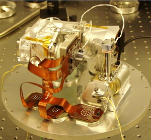
Ultra-Compact Imaging Spectrometer (UCIS) is a first-of-its-kind imaging spectrometer weighing less than 3 kg and consuming less than 3 W. The system is light and flexible enough to be used in mass- and power-constrained in situ platforms while still satisfying stringent performance specifications. Future work includes developing an instrument that could be mounted on a rover mast for determining the mineralogy of the surrounding terrain and even guiding a rover toward closer examination of scientifically important targets. This instrument would have a mast-mounted total mass of 1.5 kg (with some additional electronics potentially located on the rover body) and would open up new ways of performing geologic exploration through its ability to collect wide-angle panoramas and produce high-quality, full-range diagnostic spectra for every pixel in the image. The system would acquire approximately 500,000 spectra in the time that previous rover instruments would acquire one.
Next-Generation Imaging Spectrometers
Next-Generation Imaging Spectrometers (NGIS) are currently used by the National Ecological Observatory Network and the Carnegie Institution of Washington to study, explore, and conserve ecosystems on large geographic scales. These high fidelity, high resolution VSWIR and VNIR imaging spectrometers have better than 95% cross-track IFOV uniformity.
Next-Generation Airborne Visible and Infrared Imaging Spectrometer
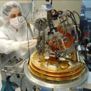
The Next-Generation Airborne Visible and Infrared Imaging Spectrometer (AVIRIS‑NG) instrument measures across the spectral range from 380 to 2510 nm at 5 nm spectral sampling with a calibrated, high-signal-to-noise-ratio spectrum measured for every spatial sample in the image. The system has been calibrated and deployed with a new high-rate data-capture system and a new real-time cloud-screening algorithm to support a methane-release experiment at the Department of Energy’s Rocky Mountain Oil Field Test Center. This instrument’s capability to detect and measure methane point sources is of interest for both greenhouse gas research and natural resource exploration, and the onboard cloud-screening algorithm is applicable for space imaging spectrometer missions.
Portable Remote Imaging Spectrometer
The Portable Remote Imaging Spectrometer (PRISM) instrument is operated by JPL as part of the Coral Reef Airborne Laboratory (CORAL), which makes high-density observations across ten coral reef regions in the Indian, Pacific, and Atlantic Oceans. Spectral images acquired by the PRISM instrument are processed and analyzed against values for biogeophysical forcings (e.g., sea surface temperature and carbonate chemistry) to produce a set of quantitative, empirical models that can be used to estimate current global reef condition and forecast reef condition under scenarios of predicted global change. With PRISM, CORAL offers the clearest, most extensive picture to date of the condition of a large portion of the world’s coral reefs from a uniform data set.
F. XO Communications, Computing & Software
_____________________________________________________________________________________
Deep Space Communications
Every NASA mission has a communications system to receive commands and other information sent from Earth to the spacecraft, and to return scientific data from the spacecraft to Earth. The vast majority of deep space missions never return to Earth. Thus, after launch, a spacecraft’s tracking and communications systems is the only means with which to interact with it. In addition, any issues with the spacecraft can only be diagnosed, repaired, or mitigated via the communications system. Without a consistently effective and efficient communications system, a successful mission would be impossible.
Communications: Increasing Demands and Extreme Challenges
The demands placed on deep space communications systems are continuously increasing. For example, as of March 2016, the Mars Reconnaissance Orbiter (MRO) had returned more than 298 terabits of data – an impressive feat. However, NASA estimates that the deep space communications capability will need to grow by nearly a factor of 10 each of the next three decades. This trend is in step with our increasing knowledge of the cosmos -- as more detailed scientific questions arise, the ability to answer them requires ever more sophisticated instruments that generate even more data. Even at its maximum data rate of 5.2 megabits per second (Mbps), MRO requires 7.5 hours to empty its onboard recorder, and 1.5 hours to send a single HiRISE image to be processed back on Earth. New high-resolution hyperspectral imagers put further demands on their communications system, requiring even higher data rates.
The principal challenge to deep space communications systems is posed by the enormous distances to which our spacecraft travel. The two Voyager spacecraft, for example, are each more than 15 billion kilometers away, about 100 astronomical units (AU; 1 AU is the average distance between Earth and the Sun). Another important challenge for deep space communications systems is to maintain their extreme reliability and versatility, in order to accommodate the long system lifetimes of most planetary missions. These challenges must be met with a communications system that uses no more than a few kilograms of mass, and often, uses only about enough power to illuminate a refrigerator light bulb.
The Deep Space Network (DSN): The Earth End of the Communications System
The Deep Space Network (DSN) consists of antenna complexes at three locations around the world, and forms the ground segment of the communications system for deep space missions. These facilities, approximately 120 longitude degrees apart on Earth, provide continuous coverage and tracking for deep space missions. Each complex includes one 70-meter antenna and a number of 34-meter antennas. These antennas may be used individually or in combination (antenna arraying) to meet each space mission’s communications requirements. A large portion of deep space communications research addresses communications system engineering, radios, antennas, transmitters, signal detectors, modulation techniques, channel coding theory, data compression, and simulation. This research also includes optical communications as well as related expertise in optical instruments, optics systems design, optical detectors, lasers, and fine-pointing systems. Deep space communications research facilities include a 34-meter research and development antenna (at the DSN complex at Goldstone, California), and the Optical Communications Telecommunications Laboratory with a 1-meter telescope (at the Table Mountain Observatory in Wrightwood, California).
Selected Research Areas
To overcome the enormous distance and spacecraft mass and power limitations in space, JPL develops deep space communications technologies for NASA’s spacecraft and the Deep Space Network (DSN). These technologies have enabled every JPL space mission ever flown and contributed to the development of exciting new mission concepts.
Radio Frequency (RF) Technologies
High-rate RF communications techniques are essential to meeting projected future mission requirements. JPL researchers are investigating new methods that would allow current radio systems to accommodate the ever-increasing need to reliably move more bits between deep space and Earth. Areas of investigation include:
- spectral-efficient technologies that increase the data rate that can be reliably transmitted within a given spectral band
- power-efficient technologies that reduce the amount of energy needed to transmit a given number of bits
- propagation effects, to better understand atmospheric modeling and allocate frequency bands
- improved flight and ground transceivers that enable future radio systems
- antennas, both flight and ground, that enable NASA’s move to higher radio frequencies such as Ka-band (26 to 40 GHz), and deployable and arraying antenna technology
Optical Communications (Laser Communications, or Lasercom)
The field of interplanetary telecommunications in the radio-frequency (RF) region has experienced an expansion of eight orders of magnitude in channel capacity since 1960. During the same period, resolution of spacecraft angular tracking, a function performed by the telecom subsystems, has seen improved by a factor of 105, from 0.1-mrad to nearly 1-nrad. Continuous performance enhancements over the past five decades were necessitated by the ever-increasing demand for higher data rates, driven in part by more complex science payloads onboard spacecraft.
Efficiency of the communications link, namely the transmitter and receiver antenna gain, are frequency dependent. JPL engineers have successfully enhanced data-rate delivery from planetary spacecraft by employing higher radio frequencies (X-band and Ka-band). Stronger signal power density can be delivered to the ground receiver using even higher optical frequencies and taking advantage of the lower achievable beam divergence. The 1/f dependence of transmitted beam-width can be practically extended to near-infrared (laser) frequencies in the 100 to 300 THz range. These frequencies can serve both planetary links over interplanetary distances, as well as shorter-distance links near Earth or near planets.
Spectral-congestion in the RF spectrum and/or performance needs should strongly motivate missions to adopt optical communications in the future; orders-of-magnitude increase in performance for the same power and mass are possible. Areas of emphasis in optical communications research and development at JPL include:
- long-haul optical communications
- optical proximity link system development
- in-situ optical transceivers
These technologies can enable streaming high definition imagery and data communications over interplanetary distances. Similarly, optical proximity link systems with low complexity and burden can boost surface asset-to-orbiter performance by a factor of 100 (20 dB) over the current state of the art. This improvement would benefit planetary and lunar orbiters to communicate with assets such as landers or rovers.
Selected Research Projects
Interplanetary Optical Communications
Optical communications is being developed at JPL for future space missions generating high volumes of data. Laser Communications (lasercom) could meet these needs for future missions to near-Earth space, the Solar System, and potentially, interstellar missions. The primary motivation for augmenting NASA’s telecommunication data rates is to enhance the science data volume returned with higher-resolution instruments and to prepare for future human deep-space exploration missions. Optical communication can provide mass, power, and volume allocation benefits over radio frequency (RF) systems, as well as bandwidth allocation restrictions.
Key challenges facing deep space optical communications include maturity of efficient, robust and reliable space laser transmitters, and a lack of data on the operating lifetime of lasers in space. Efficient laserscom links from deep space require the detection of extremely faint signals. During daylight hours, the presence of additive optical background noise despite the use of narrow band-pass filters poses a challenge to their performance. These challenges can be overcome by use of atmospheric correction techniques, which have been demonstrated successfully on meter-class ground-receiving apertures. However, atmospheric correction techniques are not yet cost effective on the 8-12 meter-diameter aperture ground receivers necessary for deep-space communications. The operation of lasercom links with sufficient availability in the presence of weather, clouds and atmospheric variability also requires cost-effective networks with site diversity.
Deep Space Optical Communications (DSOC)
The objective of the Deep Space Optical Communications (DSOC) Project is to develop key technologies for the implementation of a deep-space optical transceiver and ground receiver that will enable data rates greater than 10 times the current state-of-the-art deep space RF system (Ka-band) for a spacecraft with similar mass and power. Although a deep-space optical transceiver with 10 times the RF capability could be built with existing technology, its mass and power performance would not be competitive against existing RF telecommunications systems. The FY2010 NASA SOMD/SCaN funded Deep-space Optical Terminals (DOT) pre-phase-A project identified four key technologies that need to be advanced from TRL 3 to TRL 6 to meet this performance goal while minimizing the spacecraft’s mass and power burden. The four technologies are:
- a low-mass Isolation Pointing Assembly (IPA)
- a flight-qualified Photon Counting Camera (PCC)
- a high peak-to-average power flight Laser Transmitter Assembly (LTA)
- a high photo-detection efficiency ground Photon Counting Detector array
DSOC’s objective is to integrate a Flight Laser Transceiver (FLT) using key space technologies with an optical transceiver and state of the art electronics, software, and firmware to support a risk-retiring technology demonstration for future NASA missions. Such a technology demonstration requires ground laser transmitters and single photon-counting sensitivity ground receivers. Lasers and detectors can be integrated with existing ground telescopes for cost-effective ground transmitters and receivers.
Channel Coding
A channel code enables reliable communications over unreliable channels. By adding specific types of redundancy, the transmitted message can be recovered perfectly with high probability, even in the face of enormous channel noise and data corruption. For five decades, JPL has used its expertise in information theory and channel coding theory to develop practical, power-efficient channel codes that achieve reliable transmission from deep space to Earth. In the last 15 years, the codes have improved sufficiently to achieve data rates close to a provable theoretical maximum known as the Shannon limit.
For NASA's RF missions, JPL has developed two families of capacity-approaching codes. For the higher data rate missions, a family of low-density parity-check (LDPC) codes, now an international standard, delivers the maximum data volume within a constrained spectral band. Data rates in excess of 1 Gbps are feasible with existing commercial FPGA technology. For the lower data rates of extremely distant missions, such as to the outer planets or beyond, JPL has designed turbo codes, which can operate effectively on channels in which the noise power is more than five times the signal power.
For NASA’s optical communications missions, a fundamentally new channel coding approach is necessary to overcome the fading and phase-corrupting characteristics of a turbulent atmosphere. To meet this challenge, JPL has developed channel interleavers and photon-efficient channel codes for use with direct detection systems. The channel code, called Serially-concatenated Convolutionally-coded Pulse Position Modulation (SCPPM), provides a capacity-approaching method. SCPPM has been used on the Lunar Laser Communication Demonstration (LLCD) on the Lunar Atmosphere and Dust Environment Explorer (LADEE), which demonstrated up to 622 Mbps from lunar orbit using a 0.5 W 15 μrad beam at 1550 nm.
Image Compression
Along with research in increasing the data rate, JPL is deeply involved finding ways to compress the data as much as possible prior to transmission. Common compression techniques used on Earth, such as JPEG, are often too complex for a spacecraft’s limited computing power. JPL developed the ICER image compression technique as a replacement – it achieves the same result with substantially less complexity. ICER was used by the Spirit and Opportunity Mars rovers to return the vast majority of their imagery. Both lossless and lossy compression were used, and for the imagers used by Spirit and Opportunity, excellent image quality was typically obtained with approximately a 10:1 compression ratio.
Hyperspectral imagers represent an emerging data demand for deep-space missions. These instruments take an image at hundreds or thousands of wavelengths simultaneously, revealing the mineral content or other scientific treasures that cannot be revealed in a single visible-wavelength image. This makes the image hundreds or thousands of times larger. New image compression technology has been developed to utilize both the spatial and spectral correlations present, and to operate within the limited constraints of spacecraft processors or FPGA resources. Both lossless and lossy versions of the hyperspectral image compressors have been developed.
Reconfigurable Wideband Ground Receiver
Efforts at JPL have recently focused on the development of the Reconfigurable Wideband Ground Receiver (RWGR): a variable-rate, reprogrammable software-defined radio intended to supplement and augment the capabilities of the Block V, the standard DSN receiver. This work will address the challenge of processing high data rate telemetry (1 Gbps or higher), and is well-suited to firmware and software reconfigurability. The RWGR is an intermediate frequency (IF) sampling receiver that operates at a fixed input sampling rate. Unlike other radios that can only process signals that are integrally related to their internal clocks, the RWGR uses specially developed noncommensurate sampling to accommodate data rates that are arbitrary with respect to its internal clock. This technology provides the flexibility and reconfigurability needed for the long-term support of NASA’s signals and protocols in future deep-space missions.
Disruption Tolerant Networking (DTN)
JPL is developing technology to enable Internet-like communications with spacecraft. Unlike the Internet, however, whose protocols require latencies in the milliseconds, deep-space communications requires new protocols that can tolerant latencies or disruptions of up to several hours. For example, the roundtrip light time to the Voyager spacecraft and back is more than 24 hours. The disruption-tolerant network makes use of store-and-forward techniques within the network in order to compensate for intermittent link connectivity and delay. Many applications can benefit from the reliable delivery of messages in a disconnected network. In response to this need, NASA has established a long term, readily accessible communications test-bed onboard the International Space Station (ISS), with an arbitrary simulator of multiple network nodes in the Protocol Technology Laboratory at JPL.
Flight Transponder Technology
A spacecraft’s communications transponder is the mission’s portal to the interplanetary network. It is also the element of the spacecraft that requires the most reliability and longevity. Existing flight transponders are approaching their performance limit and are not expected to meet projected requirements of future missions. Improvements to this technology would enable the higher data rates required, support multiple spacecraft communications, and improve precision in deep space navigation.
Deep Space Navigation
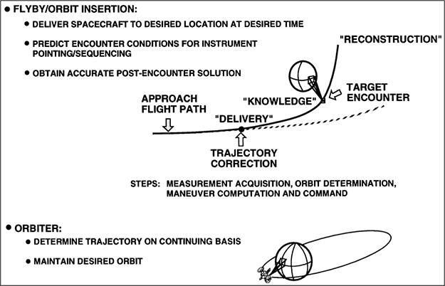 Deep space navigation enables missions to precisely target distant solar system bodies and particular sites of interest on them. Navigation takes place in real time for spacecraft operation and control. It can also be used for creating higher-fidelity reconstructions of a craft’s trajectory for future course corrections, and for scientific and operational purposes.
Spacecraft navigation includes two primary activities:
- Orbit determination, or estimation and prediction of spacecraft position and velocity
- Flight path control, or firing a rocket engine or thruster to alter a spacecraft’s velocity
Since the Earth’s own orbital parameters and inherent motions are well known, measurements of a spacecraft’s motion as seen from Earth can be converted into sun-centered orbital parameters, which are needed to describe the spacecraft’s trajectory. The meaningful measurements we can make from Earth of the spacecraft’s motion include distance from Earth, the component of its velocity that is directly toward or away from Earth, and its position in Earth’s sky.
Existing navigation techniques — Doppler, range, Delta-DOR, onboard optical — have been used in varying degrees since the early 1960s to navigate spacecraft with ever-increasing precision and accuracy. JPL’s expertise in deep space mission design and navigation has enabled many successful planetary missions to targets across the solar system using flybys, orbiters, landers, rovers and sample return spacecraft.
Future missions will build on these successful developments to meet tightening performance requirements and growing demands for spacecraft that can respond autonomously to new environments including atmospheric winds, comet outgassing jets and high radiation.
Some examples of future capabilities being explored:
- Missions consisting of multiple spacecraft could require coordinated navigation.
- Missions in the New Frontiers and Discovery classes could require development of low-thrust and low-energy mission design and navigation capabilities, as well as multiple-flyby trajectories.
- Future small-body sample-return and interior-characterization missions could require further reductions of uncertainties in navigation delivery to small bodies by an order of magnitude.
- Missions that could need very high accuracy relative to their targets will require the continued development and extension of the multimission, autonomous, onboard navigation system (AutoNav) to be a complete autonomous guidance, navigation, and control system, or AutoGNC.
Selected Research Efforts
Deep space navigation technologies have enabled every deep space mission ever flown, and JPL has been at the forefront of developing this critical capability for NASA since the agency’s beginning.
Mission Design and Navigation Methods
Deep space mission design encompasses the methods and techniques used to develop concepts for accomplishing specific scientific objectives. Navigation activities include simulations during the mission design phase and the analysis of real-time data received during mission operations. Both mission design and navigation require a large set of software tools and analysis techniques, at a variety of precision and fidelity levels, for different stages in the lifetime of a mission. These include tools and techniques for propagating and optimizing trajectories; reducing observational quantities using mathematical filtering algorithms; and simulating spacecraft guidance, attitude control and maneuvering capabilities.
JPL is investing in a comprehensive software tool suite called the Mission-Analysis Operations Navigation Toolkit Environment (MONTE) that is capable of supporting initial proposal studies through operations support and post mission trajectory reconstructions.
Precision Tracking and Guidance
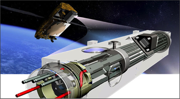
Many missions, especially those that make use of gravity assists, require high-precision tracking and guidance, since even very small delivery errors at the intermediate body or bodies are greatly magnified and must be corrected right after the flyby with potentially costly midcourse maneuvers.
Ground-based atomic clocks are the cornerstone of spacecraft navigation for most deep space missions because of their use in forming precise two-way coherent Doppler and range measurements. Until recently, it has not been possible to produce onboard time and frequency references in interplanetary applications that are comparable in accuracy and stability to those available at Deep Space Network (DSN) tracking facilities.
JPL currently is leading the development of the Deep Space Atomic Clock, or DSAC, a small, low-mass atomic clock based on mercury-ion trap technology that can provide the unprecedented time and frequency accuracy needed for next-generation deep space navigation and radio science. DSAC will provide a capability onboard a spacecraft for forming precise one-way radio metric tracking data (i.e., range, Doppler, and phase), comparable in accuracy to ground-generated two-way data. DSAC will have long-term accuracy and stability equivalent to the existing DSN time and frequency references. By greatly reducing spacecraft clock errors from radio metric tracking data, DSAC enables a shift to a more efficient, flexible, and extensible one-way navigation architecture.
In comparison to two-way navigation, one-way navigation delivers more data (doubling or tripling the amount to a user) and is more accurate (by up to 10 times).
DSAC also enables a shift toward autonomous radio navigation where the tracking data are collected (from the DSN uplink) and processed on board. In the current ground-processing paradigm, the timeliest trajectory solutions available on board are stale by several hours as a result of light-time delays and ground navigation processing time. DSAC’s onboard one-way radio tracking enables more timely trajectory solutions and an autonomous GN&C capability. This capability can significantly enhance real-time GN&C events, such as entry, descent, and landing, orbit insertion, flyby, or aerobraking, by providing the improved trajectory knowledge needed to execute these events robustly, efficiently, and more accurately.
Onboard Autonomous Navigation
Onboard autonomous guidance, navigation and control requirements have been met in the past by the JPL-led Deep Space 1, Stardust, and Deep Impact missions, which, collectively, have captured all of NASA’s close-up images of comets. For those missions, a system called AutoNav performed an autonomous navigation function, utilizing images of the target comet nucleus, computing the spacecraft position, and correcting the camera-body pointing to keep the comet nucleus in view. In the case of Deep Space 1 and Deep Impact, AutoNav corrected the spacecraft trajectory as well; and for Deep Impact, this was used to guide the impactor spacecraft to a collision with the nucleus.
Future challenges include the need to provide systems capable of orbital rendezvous, sample capture, and, eventually, sample return. This could require autonomous systems that interact with observation systems, onboard planning, and highly accurate onboard reference maps, and would include an extensive array of surface feature-recognition capabilities to provide accurate terrain-relative navigation.
JPL is investigating the development of an autonomous navigation system called the Deep Space Positioning System (DPS, like Earth bound GPS but for interplanetary space). The DPS is a collection of integrated hardware components including: a software defined radio (X-band with a computer for hosting autonomous navigation software), an optical camera and a chip scale (or DSAC) atomic clock. This unit will provide a bolt on interplanetary onboard navigation capability beyond low Earth orbit.
Positions in Space for Celestial Navigation
The JPL Solar System Ephemeris specifies the past and future positions of the sun, moon and eight planets in three-dimensional space. Many versions of this ephemeris have been produced to include improved measurements of the positions of the moon and planets and to conform to new and improved coordinate system definitions.
Lifecycle Integrated Modeling and Simulation
Lifecycle integrated modeling and simulation enables rapid and thorough exploration of trade spaces during early mission design, as well as validated high-fidelity science and engineering simulations. It targets the development of a formal framework of model verification and validation that includes quantification of uncertainties in model parameters to assess and establish performance margins.
A deep space or Earth science mission always starts with a set of questions about natural phenomena, which then evolves into specific measurement objectives and science-return requirements. These objectives and science requirements drive the mission, spacecraft system architecture, and instrument systems. As mission capabilities advance, so do the complexities of the overall system. Testing and validating mission concepts and systems using conventional testbeds is becoming progressively more challenging and, in some cases, infeasible if testing on the ground is not possible. When validated from available test data, large-scale, high-fidelity models and predictive simulations provide an important complementary testbed approach, enabling greater depth and breadth for exploring system designs and conducting engineering analyses, as well as driving selective physical testing. Similarly, predictive scientific simulations that assimilate observed data can be used to develop and assess instrument systems under development.
Advanced modeling and simulation are essential to present and future JPL missions. As an interdisciplinary activity, it enables more thorough instrument engineering, design trade-space analyses, improved science understanding, better representation of operational environments, public outreach product generation, and predictive capabilities of system performance based on quantifiable margins and uncertainties. The "trade space" can be defined as the set of program and system parameters, attributes, and characteristics required in order to be in compliance with with performance standards. These pervasive techniques contribute directly to JPL’s overall mission success.
A best case scenario would be a capability that could directly tie engineering parameters associated with flight and ground systems to advance science return, especially those parameters that drive scheduling and cost. Specific technology challenges in the area of lifecycle integrated modeling and simulation include:
- determining the degree and coupling needed or feasible for model integration;
- developing software integration between scalable (parallelizable) codes/tools and portability of code across multiple platforms;
- developing mathematical, computational, and multi-scale modeling scalability;
- verifying (assessment of the numerical correctness of the code) and validating (assessment of simulation results with experiments) models; and
- reusing models and codes libraries, including domain-specific analyses plus audits for consistency and completeness
Current Research Efforts
JPL seeks new ways to propose compelling new mission and instrument concepts while understanding and containing risks in their development. Testing and validation of these concepts as well as system designs using conventional testbeds are becoming progressively more challenging, and in some cases, infeasible. As a consequence, investment in lifecycle integrated modeling and high-fidelity simulation technologies and capabilities is needed to enable greater depth and breadth in exploring system designs and conducting engineering and scientific analyses.
Trade-Space Exploration
Examples of advanced technologies in trade-space exploration include the following:
- Engineering design modeling
- Modeling for engineering and science
- Performance and operation modeling
- Visualization for design decisions
These technologies are used for early-mission design trade-space exploration, system trades, design validation and optimization, and requirement validation for broad analyses. Optimization and simulation tools are needed to both analyze and visualize new mission architectural solutions. Immediate performance targets include multi-parameter design with rapid turnaround; systems trades that model and simulate nonlinear systems; design validation/optimization; scientific (phenomenology) modeling for in-situ remote sensing; spacecraft, instrument, and trajectory performance modeling for landers and orbiters; and incorporation of advanced visualization into the design optimization decision process.
Coupled and Integrated Physics-Based Modeling
Physically realistic models of scientific phenomena, instruments, and spacecraft are essential for Earth, planetary, and astrophysics system simulations. However, most large apertures cannot be fully tested on the ground; therefore, technologists must rely on high-fidelity simulations, including a quantification of the margins and uncertainties in the simulation results, to fully model large apertures.
High-Fidelity Model Verification and Validation
Effective large-scale, high-fidelity simulations require that model codes be rigorously verified and test-validated. Model verification is the process of determining the degree to which a computational model accurately represents the underlying assumed mathematical model and its solution. Model validation, which usually follows model verification, is the process of determining the degree to which the assumed mathematical model represents an accurate representation of the real world from the perspective of the intended application of the model. Verification of complex, integrated modeling codes is necessary to ensure that uncertainty in simulation results from software errors and numerical effects is minimized or eliminated. Extrapolation outside a limited test domain means that the models themselves have to get the right answer for the right reason. A traditional “tuning” or “calibration” of the model can make it fit a given test on the ground, but that does not mean the model is any more credible for another application. Consequently, investments in new methods and technologies are needed to verify and validate models so they can be relied upon to extensions from ground tests to flight. Performance targets include inverse statistical analyses for extrapolating model uncertainty beyond a test to another test with different inputs, and demonstration of specific methods on coupled, integrated high-fidelity models of complex systems.
Model Integration
Science and engineering models today do not transfer easily or well across mission phases or projects. One goal in model integration is to create an environment in which models are shared among multiple missions and are readily transferred from phase to phase in an integrated, synergistic fashion, covering a broad range of multidisciplinary problems associated with science and engineering.
These technologies are considered cross-cutting as they are needed for both broad analyses involved in early trade space exploration as well as deep analyses required for detailed design. Current modeling languages, environments, tools, and standards are restrictive in some aspects of expressiveness, lack formal semantics (which impedes the ability to integrate information), and lack mechanisms of model validation. Advances in formal specifications and ontologies provide the basis for robust and sound model sharing. Performance targets against specific capabilities include a semantically rich model integration framework that can integrate representations from a dozen or so models, coupled with high-fidelity and predictive simulations and the ability to connect the models through a full project lifecycle. These models would represent varying degrees of fidelity in a multidisciplinary context.
Engineering Systems Development Plan
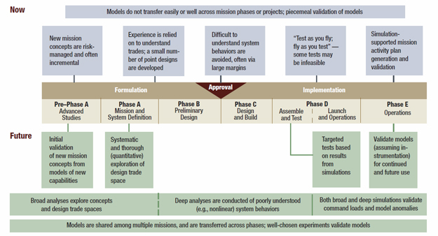
JPL’s engineering system plan encompasses many areas of modeling and simulation development will take place over the next decade. JPL is working to further improve upon its state-of-the-art software capabilities to simulate, model, and plan for future missions.
Integrated Model-Centric Engineering
The JPL Engineering & Science Directorate intends to establish integrated model-centric engineering as "the way of doing business" in order to reduce duplication of information and promote the definition, control and verification & validation of streamlined and high-quality systems engineering products across both systems and subsystems.
Integrated Model-Centric Engineering (IMCE) is the JPL initiative to formalize and accelerate the application and integration of models across disciplines (mechanical, electrical, telecommunication, etc.), across engineering levels (system, subsystems and components), and across the full project life cycle (formulation, design, integration, verification and operations). The objective is to advance from document-centric engineering practices to one in which structural, behavioral, physics and simulation-based models representing the technical designs are integrated and evolve throughout the life-cycle, supporting trade studies, requirements analyses, design verification, and system V&V. The IMCE initiative facilitates this transition by providing: modeling development environment and standards; reusable models repository; tool/model integration; training; user community support; and partnership.
Select Research Projects
Dynamics And Real-Time Simulation (DARTS)
DARTS is a high-performance computational engine for flexible multi-body dynamics. It is an advanced high-fidelity, multi-mission simulation tool for the closed-loop development and testing of spaceflight systems. The DARTS simulator is based on algorithms from the Spatial Operator Algebra mathematical framework. It has been used for many of JPL’s successful missions, such as Galileo, Cassini, Mars Exploration Rover (MER), Stardust and the Mars Science Laboratory (MSL) mission.
Model-Based Systems Engineering and Architectures
Model-based systems for engineering and architectures is an analysis capability that integrates modeling, mission simulation, data analysis, computational technologies, data management, and visualization to help formulate and validate advanced instruments and associated payload systems. The goal of this new, yet maturing, area is to establish a simulation-oriented basis for developing, validating, and adopting new smart-instrument technologies and associated flight architectures for the next generation of Earth and space exploration missions.
High-Capability Computing and Modeling
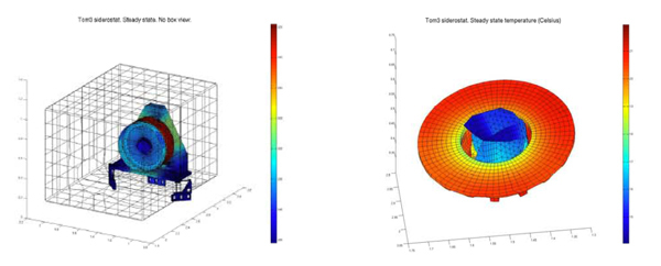
Researchers in this area provide expertise in implementing legacy applications or in developing new software on large-scale distributed-computing platforms such as cluster computers. The capability has been demonstrated on legacy applications from engineering such as antenna modeling and trajectory design software, and from science such as atmospheric chemistry, radiative transfer, tsunami, and gravity-inversion models.
Corps Battle Simulation (CBS)
CBS supports training of Army Division & Corps commanders and their staffs in dynamic, stressing combat situations. CBS is part of an infrastructure that senior Army commanders and their staffs use in “wargame” operations. These games allow commanders to learn lessons from simulations that they can apply to real battle scenarios.
CI OSSE Field Experiment
The Cyberinfrastructure (CI) component of the Ocean Observing System (OOI) is conducting an Observing System Simulation Experiment (OSSE) to test the capabilities of the OOI CI to support field operations in a distributed ocean observatory in the Mid-Atlantic Bight. The CI OSSE goal is to provide a real oceanographic test bed in which the CI will support field operations of ships and mobile platforms, aggregate data from fixed platforms, shore-based radars, and satellites and offer these data streams to data assimilation and forecast models. For the first time, this CI OSSE will construct a multi-model ensemble forecast that will be used to guide the glider deployment and trigger satellite imaging over the region of interests.
Integrated Modeling and Simulation for Large Apertures (IMSLA)
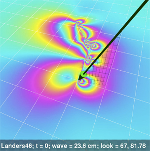
IMSLA is a system for advanced computational simulation that integrates heat-transfer, structural-analysis, parallel-computing and optical-aberration capabilities within the Cielo code environment, producing models in which these characteristics are integrated. Such models are vital to the development of future precision, space-based, large-aperture optical systems such as the James Webb Space Telescope (JWST). These instruments will be deployed in microgravity, cryogenic environments and will be expected to operate at extraordinarily high levels of optical precision under automated thermal and mechanical control, but are impractical to fully ground-test prior to launch.
Quakesim
QuakeSim is a project to develop a solid Earth science framework for modeling and understanding earthquake and tectonic processes. The multi-scale nature of earthquakes requires integrating many data types and models to fully simulate and understand the earthquake process. QuakeSim focuses on modeling the inter-seismic process through various boundary element, finite element, and analytic applications, which run on various platforms including desktop and high-end computers. Such work is essential to full realization of the science value in future earth-sensing missions such as interferometric radar.
Mission System Software
Mission systems are integral to the development and operation of JPL’s spacecraft. Orbiters and in-situ spacecraft all utilize mission system software for design analysis, planning, engineering and science data analysis, and anomaly investigation.
The primary objectives for mission system research are to:
- Enable more effective utilization of spacecraft resources
- Reduce the cost of spacecraft operations
An additional objective is to increase capabilities to enable more complex missions and more sophisticated instruments.
Selected Research Areas
Virtual ‘In-Situ’ Surface Operations Planning
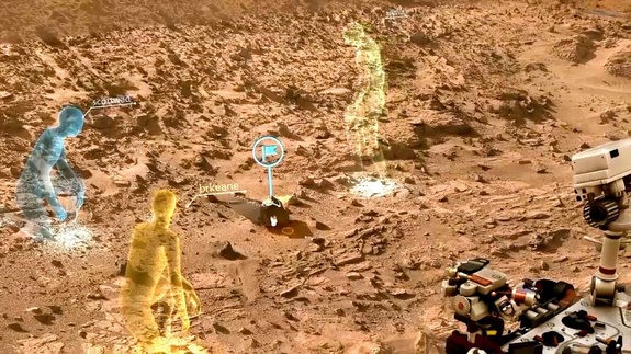
Mars surface operations planning has traditionally revolved around analysis of two-dimensional images taken by surface rovers and overhead spacecraft. OnSight is a new technology that connects scientists and engineers with the environment of the Mars rovers through a virtual presence. Using actual Mars rover imagery and Microsoft’s HoloLens holographic computer, a 360 degree, 3-dimensional view of the Martian terrain is presented to scientists and mission planners. Multiple users can ‘move’ around the Martian terrain to examine physical features and to plan rover operations.
Mission and Instrument Operations Planning
Operations planning represents a significant area for research. Typical planning activities involve:
- Human analysis of data collected during prior observations
- Manual selection of new observation targets
- Assembling of observational campaigns
This current process can be labor-intensive. Future capabilities could automate the analysis of observation data and the development of both tactical and strategic operations plans. This improvement in efficiency could enable a faster planning process, perhaps including in-situ development of operations plans in real-time. Overall, this automation could enable a more effective and less costly planning process.
Mission Control Technology
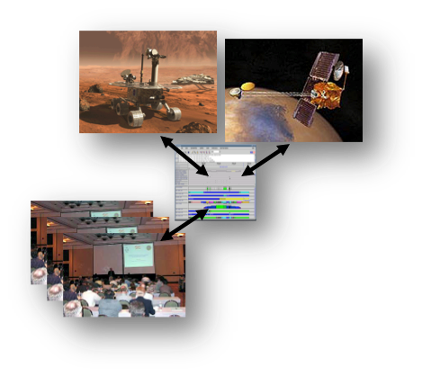
Mission control technologies provide tactical and strategic direction for spacecraft operations. Requests for specific science investigations, requirements from engineers to maintain spacecraft health, and responses to current spacecraft conditions all need to be accounted for. Research areas target improving the level of ground-based automation for spacecraft commanding through more efficient analysis of telemetry data, and through the use of standardized command and telemetry dictionary representations.
Data Management Technology
Data management, analysis, and trending is critical to determining spacecraft health. Research includes developing flexible correlation and comparison techniques for telemetry data.
Spacecraft Analysis Technology

Models of spacecraft state and performance provide mission systems with tools for predictive and analytical evaluation of spacecraft health and status. Research in this area includes the development of high-fidelity models of spacecraft instruments and subsystems, as well the capability to quickly and easily integrate these models to develop a more comprehensive estimate of spacecraft status.
These models are used at various phases in a mission’s lifecycle. During the design and pre-launch phases, models are used to evaluate designs and predict the limits of spacecraft performance. Post-launch, models would be used to evaluate spacecraft health and analyze any operational anomalies. Additionally they can be used to develop and analyze scientific data collection campaigns.
Cyber Defense
Increasing system and software complexity coupled with increasing adversarial activity underscores the need to improve the defensive posture of JPL missions against cyber attacks. Currently, the cyber protections applied across JPL vary, based partly on differing risk profiles as well as incomplete knowledge of cyber threats. Such differences in the implementation of protections carries risk to neighboring systems that may have different risk acceptance profiles.
JPL’s Cyber Defense and Information Architecture (CDIA) team is working to raise awareness of, and to address, the threats that missions and infrastructure face. The team is developing a repeatable framework for assessing cyber risk across programs and projects. CDIA is engaged in research and development of cyber-focused, integrated, executable models for the protection of critical infrastructure for oil and gas facilities (Chevron) and the power grid (DoE). The team’s models help identify areas of weaknesses in cyber defenses and determine where risks exist in key aspects of physical plants and infrastructure. Constructing these cyber-focused, integrated models for JPL missions would help defend JPL-specific systems and projects against cyber adversaries.
Furthermore, there is a need to model data flows and trust profiles between JPL and its various partners. There are emerging responsibilities should JPL be the victim or the conveyed source of a cyber attack from or to a partner facility. The CDIA is creating a cyber defense laboratory that will enable the validation of defensive architectures, designs and solutions in a principled and repeatable manner. Specifically, the results that are targeted will advance and broaden core JPL competencies in modeling and verification and validation (V&V) to the important new arena of cyberspace.
Strong support and research is greatly needed in the area of hardening the current mission infrastructure to better detect, diagnose and respond to live adversarial activity and/or intrusion attempts. Such effort would include tasks aimed at understanding and capturing nominal environment baseline data in order to detect:
- anomalous system behavior
- changes in system configurations
- changes in workflow
- alterations to low-level system communications
These could be indicative of penetration or compromise. Mission systems need to support situational awareness to detect, diagnose and remediate the consequences of cyber attacks.
JPL missions can receive, transmit and process terabytes of science and engineering data every day for decades. However, not all of that data presents the same risk and vulnerability to a mission, the institution, or partners -- the sensitivity of command data is very different from the sensitivity of ephemerides. Additional research is on the horizon in the area of adaptively supporting security attributes such as confidentiality, integrity, and availability of data where resources may not allow for comprehensive security coverage. The ultimate goal is to better understand how to address dynamic changes to security attributes as the threat environment evolves or risk postures change.
G.XO Spacecraft & Robotic Technologies
______________________________________________________
Spacecraft technologies and subsystems focus on the platform for carrying payload, instruments, and other mission-oriented equipment in space.
Advanced Propulsion and Power
Robotic exploration of our Solar System is made possible by the ability to propel and deliver a spacecraft to its destination (and sometimes back to Earth), and to provide the power required to operate the instruments and systems that acquire scientific data and transmit them back to Earth. Challenging deep-space missions frequently require large spacecraft velocity changes (delta-v) from advanced propulsion systems to reach their target and maneuver to obtain data and samples, and the missions often need significant power in extreme environments. Advanced propulsion and power systems are thus critical elements in spacecraft design and play a role in determining overall mission capabilities and performance.
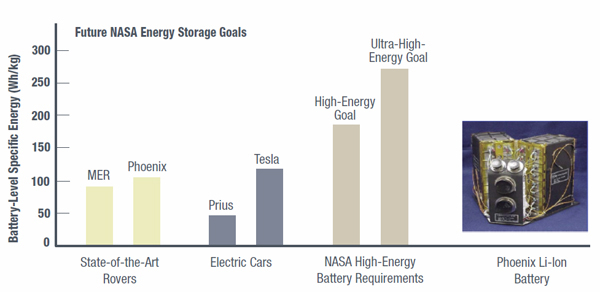
The future of deep-space exploration depends on developing technologies in five key areas of advanced propulsion and power:
- Electric propulsion: Increased capabilities and higher-efficiency thrusters are being developed to reduce cost and risk, and to enable credible mission proposals.
- Chemical propulsion: Future large mission classes depend on increased capabilities in feed systems -- such as pressurization systems, low-mass tanks, and cryogenic storage components. In addition, advances in propulsion-system modeling are being developed to increase chemical thruster capabilities.
- Precision propulsion: Advances are being made in micro- and milli-newton thruster development to provide extended life and reliability for precision formation flying and orbit control in next-generation Earth-observation and other science missions.
- Power systems: Higher-efficiency and higher-specific-power solar arrays and radioisotope power systems are desired to provide increased power and mission design flexibility for deep-space missions.
- Energy storage: Improved primary batteries, rechargeable batteries, and fuel cells with high specific energy and long-life capability are needed for the extreme environments that will be faced by future missions. Advances in these technologies would make more challenging missions possible and could reduce the system cost sufficiently to enable new Flagship, New Frontiers, Discovery, and space physics missions.
Selected Research Projects/Areas of Research
Advanced Electric-Propulsion Technologies
Advanced electric-propulsion technologies consist of electric-propulsion systems based on ion and Hall thrusters. These capabilities were successfully demonstrated on the Deep Space 1 and Dawn missions. Because electric-propulsion systems can deliver more mass for deep-space missions and can accommodate flexible launch dates and trajectories, they could enable many future missions. Development of an electric-propulsion stage using advanced thruster technologies and accompanying components, including solar electric power sources, is critically needed for future flagship missions and would be directly applicable to other missions as the technology matures and costs decrease. Solar electric propulsion is presently flying on Dawn, which uses 2.3 kW NASA Solar Electric Propulsion Technology Application Readiness (NSTAR) engines. Other thruster technologies are emerging with higher power, thrust, and specific impulse (Isp) capabilities.
Advanced Chemical-Propulsion Technologies
Advanced chemical-propulsion technologies include milli-newton thrusters, monopropellant thrusters, ultra-lightweight tanks, and 100 to 200 lb–class bipropellant thrusters. Advances are being made to improve thruster performance and reduce risk and costs for attitude control system, and entry, descent, and landing (EDL) systems. Specific improvements include the development of electronic regulation of pressurization systems for propellant tanks, lower-mass tanks, pump-fed thruster development, and variable-thrust bipropellant engine modeling, as well as deep-space-propulsion improvements in cryogenic propellant storage systems and components.
Precision Micro/Nano Propulsion
Advanced thrusters are required for precision motion control/repositioning and high Isp for low-mass, multiyear missions. Solar pressure and aerodynamic drag compensation and repositioning requirements dictate Isp and thrust level, while precision control of attitude and interspacecraft distance drive minimum impulse. These thrusters produce micronewton thrust levels for solar-wind compensation and precision-attitude control. Precision noncontaminating propulsion is needed, especially for science missions with cryogenic optics and close-proximity spacecraft operations, to keep payload optical/infrared surfaces and guidance-navigation-control sensors pristine. Additional requirements are for high-efficiency thrusters that enable 5- to 10-year mission lifetimes that include significant maneuvering requirements. Performance targets for micro/nano propulsion include a miniature xenon thruster throttleable in the 0–3 mN range and with a 10-year life. Continued development and flight qualification of this thruster is required for some potential future missions.
Power Sources for Deep-Space Missions
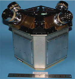
Power source options for deep-space missions include solar cell arrays and radioisotope power systems (RPS). Solar arrays with specific power in the range of 40–80 W/kg are currently used in Earth-orbital missions and deep-space missions at distances up to about 4 AU. Future orbital and deep space missions may require advanced solar arrays with higher efficiency ( > 35%), and high specific power ( > 200 W/kg). Some deep space and planetary-surface missions may require advanced solar arrays capable of operating in extreme environments (radiation, low temperatures, high temperatures, dust). Using advanced materials and novel synthesis techniques, such high-efficiency solar cells and arrays are under development for use in future spacecraft applications. These advanced cells would increase power availability and reduce solar array size for a given power, and may also have applications for terrestrial energy production applications as well, if fabrication costs can be driven to sufficiently low levels.
Radioisotope power systems (RPS) with specific power of ~3 W/kg are currently used in most deep-space missions beyond ~4 AU, or for planetary surface missions where there is limited sunlight. JPL has long used RPS for deep space missions, including Voyager, Galileo, and Cassini, and will be using RPS for the Mars Science Lander (MSL), the next Mars rover. Future deep-space missions may require advanced RPS with long-life capability ( > 20 years), higher conversion efficiency ( > 10%), and higher specific power ( > 6 W/kg). Some deep-space mission concepts require the ability to operate in high radiation environments. Advanced thermoelectric radioisotope generators are under development by NASA for future space missions. The capabilities of smaller RPS are being explored for future exploration missions. The development of small RPS can enable smaller landers at extreme latitudes or regions of low solar illumination, subsurface probes, and deep-space microsatellites.
Energy Storage for Deep-Space Missions
The energy storage systems presently being used in space science missions include both primary and rechargeable batteries. Fuel cells are also being used in some human space missions. Primary batteries with specific energy of ~250 Wh/kg are currently used in missions such as planetary probes, landers, rovers, and sample-return capsules where one-time usage is sufficient. Advanced primary batteries with high specific energy ( > 500 Wh/kg) and long storage-life capability ( > 15 years) may be required for future missions. Some planetary surface missions would require primary batteries that can operate in extreme environments (high temperatures, low temperatures, and high radiation). JPL, in partnership with industry, is presently developing high-temperature ( > 400 ºC) and high-specific-energy primary batteries (lithium–cobalt sulfide, LiCoS2 ) for Venus surface missions and low-temperature ( < ?80 ºC) primary batteries (lithium–carbon monofluoride, LiCFX) for Mars and outer-planet surface missions. Rechargeable batteries with specific energies of ~100 Wh/ kg are currently used in robotic and human space missions (orbiters, landers, and rovers) as electrical energy storage devices. Advanced rechargeable batteries with high specific energy ( > 200 Wh/kg) and long-life capability ( > 15 years) may be required for future space missions. Some missions could require operational capability in extreme environments (low temperature, high temperature, and high radiation). JPL, in partnership with other NASA centers, is presently developing high-energy-density Li ion batteries ( > 200 Wh/kg) that can operate at low temperatures (~ ?60 °C) for future space missions.
Fuel cells, such as those used on the Space Shuttle, can be particularly attractive for human space science missions. These fuel cells have specific power in the range of 70–100 W/kg and a life of ~2500 h. Advanced fuel cells with high specific power (200 W/kg), higher efficiency ( > 75%), long-life capability ( > 15,000 h), and higher specific power may be needed for future human space missions. JPL is working on the development of such advanced fuel cells.
Autonomy
JPL designs and builds systems that achieve incredibly ambitious goals, as evidenced by the Curiosity rover traversing on Mars, the highly complex Cassini spacecraft orbiting Saturn, and the compelling concept for retrieving a boulder from an asteroid and inserting it into a lunar orbit to create a nearby target to be investigated by astronauts. Autonomy -- which includes creating and optimizing spacecraft activity plans, executing nominal and critical activities, analyzing and interpreting data, assessing system health and environmental conditions, and diagnosing and responding to off-nominal situations -- is a fundamental part of achieving these goals.
A spacecraft’s ability to sense, plan, decide, and take actions to accomplish science and other mission objectives depends on the flight systems that implement the intended functionality and the operators who command them. Historically, success has depended on an ability to predict the relevant details of remote environments well enough to perform the mission safely and effectively.
As NASA and JPL advance our knowledge frontier, science questions become more sophisticated and mission environments more difficult, harsh, and inaccessible. This leads to new challenges as shown in the following examples:
- Hazardous conditions such as the high radiation levels surrounding interesting destinations like Europa and the toxic atmospheres of planetary bodies like Venus limit mission lifetime and leave multiple complex activities with very few possible ground interventions.
- Concepts for missions to free-floating, active small bodies and other destinations with unconstrained or unknown environments need more sophisticated perception-rich behaviors and flexible in situ decision-making (see also Robotics section).
- Multi-element missions, such as a potential Mars Sample Return, which would involve physical interaction of multiple systems to capture and transfer samples as well as launching off of another celestial body (see also Robotics section).
- Concepts for long-duration missions such as the Kuiper Belt exploration and ambitious interstellar explorers must operate in unknown environments and survive equipment failures over the course of decades.
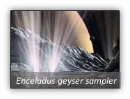 |  |  |
Because science investigations are expected to deliver increasingly exciting results and discoveries, systems are becoming progressively complex and engineering designs must adapt by improving in situ functionality. For example, these compelling yet challenging investigations will need to revise their operational tactics—and sometimes even their science objectives—“on the fly” in response to unforeseen mission risks, requiring unprecedented onboard decision-making on short timescales. As missions visit more distant and formidable locations, the job of the operations team becomes more challenging, increasing the need for autonomy.
Autonomy capabilities have the potential to advance rapidly, and they must do so to support next-generation space science and exploration goals. Advances in autonomous behaviors and decision-making and related fields that come from the academic, industry, and government arenas are being adapted for space system applications. At the same time, current mission approaches are reaching the limits of what can be accomplished without such advances. JPL currently strives for autonomy technology development, maturation, and infusion in six principal areas:
- Planning, scheduling, and execution
- Robust critical activities
- In situ data interpretation and learning
- State-awareness and system health management
- Perception-rich behaviors (see Robotics section)
- Physical interaction (see Robotics section)
Selected Research Topics
The functionality requirements of science missions will, and must, continue to evolve, yet the need for extreme reliability in flight systems remains a critical factor. In the past, deep-space missions were commanded almost entirely from the ground, with ingenuity and patience overcoming the difficulties of light-time delays. Except during critical events such as entry, descent, and landing on Mars and one-time activities such as orbit insertions, reliability was achieved largely via “safing” responses that used block-level redundancy with fail-over based on straightforward, simplistic system behavior checks. Now that surface missions—with their continuous uncertainties associated with operating on a planetary surface—are an established mission class, meeting science objectives requires real-time, goal-directed, situationally aware decision-making. To meet these needs, technological capabilities are evolving to close more decision loops onboard the spacecraft, both for mission planning and operations and for fault response. Future spacecraft and space missions will rely heavily on the in situ decision-making enabled by designing for autonomy in both hardware- and software-based functionality.
JPL’s autonomous operations capabilities include automated planning, intelligent data understanding, execution of robust critical activities such as entry, descent and landing (EDL), and situational- and self-awareness. These capabilities can be used in both flight and ground systems to support both deep-space and Earth-orbiting missions. Autonomous operations involve a range of automated behaviors for spacecraft including onboard science event detection and response, rapid turnaround of ground science plans, and efficient re-planning and recovery in response to anomalous events. Successes in this area include (1) the use of onboard image analysis to automatically identify and measure high-priority science targets for the rovers on Mars and (2) the use of automated planning onboard an Earth satellite to manage routine science activities and automatically record events such as volcanic eruptions, flooding, and changes to polar ice caps.
Planning, Scheduling, and Execution
An important autonomy capability for current and future spacecraft is onboard decision-making, where spacecraft activity plans are autonomously created and executed, enabling a spacecraft to safely achieve a set of science goals without frequent human intervention. To provide this capability, planning, scheduling, and execution software must be capable of rapidly creating and validating spacecraft plans based on a rich model of spacecraft operations. Plans typically correspond to spacecraft command sequences that are executed onboard and that ensure the spacecraft is operated within safe boundaries. For each spacecraft application, the planning system contains a model of spacecraft operations that describes resource, state, temporal, and other spacecraft operability constraints. This information enables the planning system to predict resource consumption, such as power usage, of variable-duration activities, keep track of available resource levels, and ensure that generated plans do not exceed resource limits. Planning and scheduling capabilities typically include a constraint management system for reasoning about and maintaining constraints during plan generation and execution as well as a number of search strategies for quickly determining valid plans. A graphical interface provides visualizing the plans/schedules to operators on the ground.
Once plans are generated, plan execution can be monitored onboard to ensure plan activities are executed successfully. If unexpected events such as larger-than-predicted power usage or identification of new science goals occur, plans can be dynamically modified to accommodate the new data. To support re-planning capabilities, a planning system monitors the current spacecraft state and the execution status of plan activities. As this information is acquired, future-plan projections are updated. These updates may cause new conflicts and/or opportunities to arise, requiring the planning system to re-plan to accommodate the new data. In order to reason about science goal priorities and other plan quality measures, optimization capabilities can be used to search for a higher quality plan. User-defined preferences can be incorporated and plan quality computed based on how well the plan satisfies these preferences. Plan optimization can also be performed in an iterative fashion, where searches are continually performed for plan modifications that could improve the overall plan score.
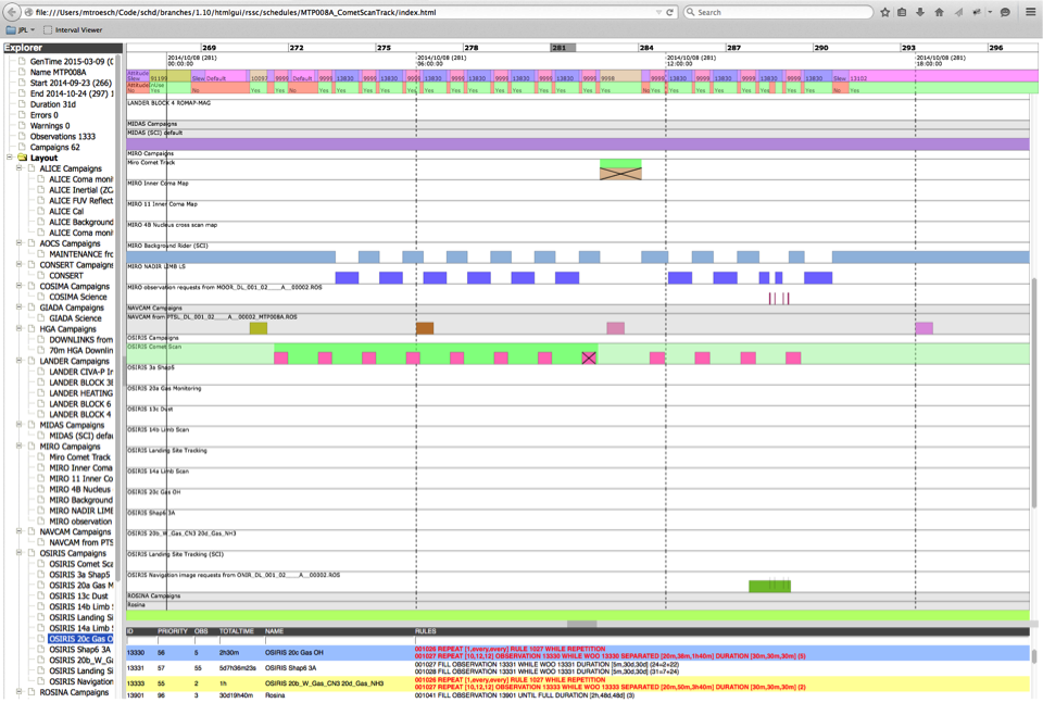
Robust Critical Activities
Communication delays and constraints often preclude direct ground-in-the-loop involvement during critical activities such as entry, descent, landing, orbit insertions, proximity operations, and observation of transient phenomena; therefore, JPL’s space assets must rely on onboard control and autonomy. Future missions likely will have more challenging requirements for operating in even more complex and less known space and planetary environments. These include major shrinking of landing ellipses, closer and more precise proximity operations (e.g., touch-and-go sampling maneuvers and flying through and taking samples of vents and geysers), and more complex measurements of transient phenomena. Along with the evolving and sophisticated sensing suite, these demanding requirements call for more capable onboard reasoning and decision-making for critical real-time applications. Capabilities such as terrain relative navigation, terrain hazard assessment for landing, onboard nonlinear state estimation, sensor fusion, real-time optimal guidance laws for trajectory planning with constraints, and coordinated multi-instrument observations require sophisticated onboard computing and reasoning about larger volumes of data with greater uncertainty. JPL is developing novel, cost-effective techniques to mature, validate, and verify these sophisticated system capabilities for infusion into future missions.
In Situ Data Interpretation and Learning
Autonomous capabilities continue to extend the reach of science investigations conducted by remote spacecraft while maintaining system reliability and managing risk. Applications include triaging data for downlink when more data is collected than can be transmitted immediately to Earth and responding to features and events in the remote environment more rapidly than would be possible with the ground in the loop. Past examples include:
- Volcano and flood detection onboard Earth-orbiting spacecraft, enabling rapid follow-up imaging;
- Real-time detection of methane during airborne campaigns, enabling adjustment of the flight path to track the plume and identify and characterize the source;
- Detection of interesting geologic features in rover imagery data and subsequent triggering of the collection of follow-up detail imagery in the same operations sol;
- Dust-devil detection onboard Mars rovers.
Future applications include the use of onboard landmark detection and matching to provide pinpoint landing for Mars surface missions and the use of onboard data understanding and dynamic instrument parameter adjustment to provide rapid event detection and response for missions to primitive bodies.
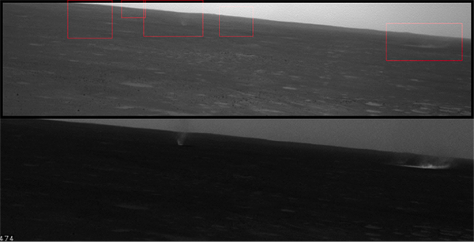
State-Awareness and System Health Management
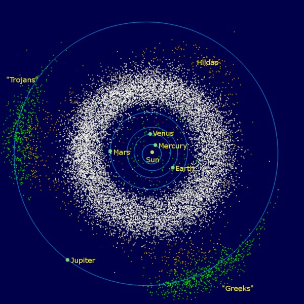
In order to accomplish increasingly ambitious exploration goals in unknown environments, the space systems must have sufficient knowledge and capabilities to realize these goals and to identify and respond to off-nominal conditions. Decisions made by a system—or by its operators—are only as good as the quality of knowledge about the state of the system and its environment. In highly complex and increasingly autonomous spacecraft systems, state-awareness, which includes both situational-awareness and self-awareness, is critical for managing the unprecedented amount of uncertainty in knowledge of the state of the systems and the environments to be explored in future missions. This uncertainty introduces significant risk, challenging our ability to validate our systems’ behaviors effectively and decreasing the likelihood that our systems will exhibit correct behaviors at execution time. Endowing our systems with the ability to assess explicitly their state, the state of the environments they operate in, and the associated uncertainties will enable them to make more appropriate and prudent decisions, resulting in greater system resilience. Technologies for state-awareness range from traditional state filters (e.g., Kalman filters) for nominal state estimation and traditional fault protection software (e.g., auto-coded state machines) for off-nominal state diagnosis to more sophisticated model-based estimation and diagnosis capabilities that leverage advances in the field of model-based reasoning.
The spacecraft that support these challenging future missions will need to be capable of reasoning about their own state and the state of their environment in order to predict and avoid hazardous conditions, recover from internal failures, and meet critical science objectives in the presence of substantial uncertainties. System health management (SHM) is the crosscutting discipline of designing a system to preserve assets and continue to function even in the presence of faults. As science goals become more ambitious and our systems are sent to increasingly challenging environments, the simple “safing” response of the past is no longer a viable option. Critical events such as orbit insertion and landing, are extreme examples of the need for more sophisticated responses to faults, since it is impossible to stop the activity and wait for ground operators to diagnose the problem and then to transmit recovery commands; in the time it takes to close the loop with the ground, the opportunity to accomplish the event will have been lost already. Instead, systems must degrade gracefully in harsh environments such as Venus, and they must have the ability to fly through failures in order to complete critical events. Researchers are investigating model-based techniques that will provide a spacecraft with sufficient information to understand its own state and the state of the environment so that it can reason about its goals and work around anomalies when they occur.
Avionics and Flight Software
JPL spacecraft collect scientific data to further our understanding of Earth, the Solar System, and the Universe. Onboard electronics take data from the instruments, store it, process it, and package it for transmission back to Earth. Spacecraft often operate far from Earth and communicate only infrequently with ground controllers. All the software and autonomy that allows these spacecraft to function and implement commands from the ground is hosted by the spacecraft electronics -- the avionics.
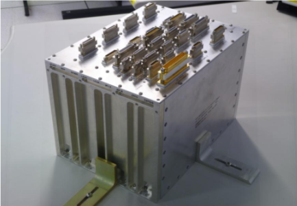
For the many spacecraft operating at large distances from Earth, much -- if not all -- of the short-term decision-making in the spacecraft operation must be performed autonomously onboard the spacecraft themselves because of the light delay in commanding from Earth. For spacecraft at Mars, this light delay means that communications from ground controllers take between 4 and 21 minutes to arrive; for spacecraft in the outer Solar System, it can take several hours each way. The spacecraft themselves need to be smart and independent, knowing how to perform their own basic housekeeping as well as more advanced science processing such as science data evaluation and analysis. Since physical repair is impossible at these distances, spacecraft need autonomous detection and resolution of problems if they are to continue the mission even after components have failed. Robust identification and tolerance of faults are of the utmost importance.
The avionics -- and the flight software hosted within the avionics -- form the central nervous system and brain of the spacecraft, constantly monitoring the health of the system, keeping it working, and making decisions on what to do next. In the future, spacecraft will have smarter brains, enabling increased autonomy (spacecraft will require less and less involvement from ground operators) and improved capability (spacecraft will perform increasingly complex scientific investigations). To make future spacecraft more capable and more robust, JPL is actively involved in advancing avionics and flight software in a variety of technological research areas:
- Spaceflight computing architectures and multicore processing
- Computational capabilities
- Software modeling
- Mission operations automation
- Software reliability and fault-tolerant flight software architectures
Selected Research Topics
Spaceflight Computing Architectures and Multicore Processing
Today’s state-of-the-art deep-space spacecraft have a single prime control processor at the center of their avionics, and this limits the amount of processing power available, the robustness of the system to faults, and the timeliness of responses to errors in the processor. A redundant processing box with an additional copy of the processor can be added to cover these faults and increase robustness, but this adds mass and power consumption and makes timely response to faults on the primary processor more challenging. JPL is investigating how to reduce the mass and power consumption of the avionics and increase the robustness and flexibility of the electrical hardware.
One area of active research is the use of simultaneous multicore processing. Not only does multicore provide additional processing power when needed, it could also allow smarter power management by reducing the number of active cores -- and, therefore, the power consumption -- when mission conditions demand it. When combined with time- and space-functional partitioning, multicore processing could improve system robustness by routing around failed cores autonomously and dynamically. This could enable active recovery in the presence of hardware and software faults in scenarios such as entry, descent, and landing on planetary surfaces, something that is now impossible due to extremely low control outage requirements.
JPL is also making advances in fundamental spaceflight computing architectures that could allow capabilities and designs to be shared across missions of vastly different scales and objectives. These scalable and tunable computing architectures could provide increased computational capability and a common architectural framework for all JPL missions, from CubeSats and SmallSats to flagship outer planet missions. Since these architectures are inherently very low power and low mass, missions could also benefit from having more spacecraft resources (mass, power, volume) available for scientific investigations. These computing architectures could provide the scalability and robustness to host complex, possibly mission-critical, autonomous software behaviors that would further scientific return.
Computational Capabilities
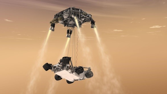
Robotic spacecraft continue to become more advanced and more autonomous to increase mission returns and enable novel scientific investigations. Path planning, decision-making, and complex onboard science data analysis are only a handful of the autonomous capabilities currently being investigated, and JPL is researching space-rated, high reliability, high performance computing resources to support these capabilities.
Greater autonomy and scientific return could be achieved by giving spacecraft the ability to perform high-performance and complex software codes remotely. For example, high-speed data compression, complex onboard hyperspectral analysis, and multi-sensor data fusion could allow more data to be returned to scientists on Earth. High performance computational capabilities could allow spacecraft to perform activities that were previously impossible, such as autonomous terrain-relative navigation. This computing power could also allow spacecraft to perform complex scientific target selection and evaluations without having to wait for instructions from ground control.
Software Modeling
Various basic research activities are currently being conducted to enhance the software development process, with the objective of producing more robust flight applications. Model-based system engineering (MBSE) has been gaining acceptance and is being applied as standard methodology to specify system requirements for various flight projects. It has the benefit of being more precise in specifying system behavior than informal English text requirements that may be subject to ambiguity in interpretation during design and implementation. To facilitate the transition from traditional methods of system specifications to more precise MBSE methods such as SysML notations, a textual modeling language named K (Kernel language) is being developed for the Europa project. The objective is to provide sufficiently rich semantics that all system model designs can be represented by this language. This language is similar to known formal specification languages and is inspired by SysML in representing a relational view of models. The expression sublanguage of K can be used to specify constraints in the models, even in a graphical context (e.g., textual expressions in block diagrams). A system engineer with basic programming knowledge can readily learn and apply this technique for system specification, thus facilitating the MBSE adoption process. There is ongoing research to develop analysis capabilities on top of the K language. The grammar (parser) and type checker are already complete, and a translator to an automated theorem prover is currently in progress.
Mission Operations Automation
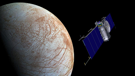
Mission operations rely on downlink telemetry to inform the operators about the successful execution of uplink commands and the health status of the flight system. Two major categories of telemetry data are analyzed in support of operations: event reporting (EVR) and channelized state data (EHA). For missions such as Mars Science Laboratory (MSL), there are approximately 4,000 data channels and 26,000 EVR message types. Continuously monitoring and evaluating EVRs and EHA values is a major undertaking for mission operators. There are many scenarios when multiple EVR(s) and EHA data from different time points need to be analyzed and correlated for health assessment.
To ease the effort by a human operator, a monitoring tool called DASHBOARD has been developed to automate the monitoring and analysis function. The key DASHBOARD technology is the rule-based engine LogFire, which was developed in-house and is coupled to a telemetry retrieval tool. The methods of telemetry data analysis are expressed as rules using the LogFire domain specific language and running the rule-based engine for analysis. This tool is capable of quickly processing large volumes of data and automatically performing the analysis more completely for many complex scenarios. It has benefitted the MSL operations team tremendously in conducting their daily routines. In addition to supporting operations, the tool can be applied to sequence validation prior to uplink as well as to verification and validation testing during development. With its demonstrated effectiveness, this tool has been incorporated as a standard feature for future ground systems and will have lasting benefits to JPL operations.
A precursor of LogFire, the JPL-developed tool named TraceContract (a log analysis tool based on state machines and temporal logic), was used by mission operations at the NASA Ames Research Center during the entire LADEE (Lunar Atmosphere and Dust Environment Explorer) Mission to check command sequences against flight rules before submission to the LADEE spacecraft.
Software Reliability and Fault-Tolerant Flight Software Architectures
As spacecraft become increasingly capable and are tasked with performing increasingly challenging missions, the amount of software code they require increases substantially. At the same time, hardware reliability advanced, and mature processes have been put in place to decrease the likelihood of hardware failures. Ensuring the reliability of the software has become increasingly complex and challenging. This is of the utmost importance to JPL’s space missions because robotic spacecraft frequently operate outside the view of ground controllers and at a significant light time delay with respect to Earth. For much of the duration of such a mission, the success of the spacecraft is fully within the control of the onboard flight software. In the event of a fault onboard the spacecraft, it is the flight software that must regain control of the spacecraft, make sure that it is in a safe state (power, thermal, and communications), and then re-establish contact with Earth. More challengingly, this also includes being able to recover from faults or anomalies within the flight software itself.
JPL is working to develop even more robust flight software architectures to ensure continued safe operation in the face of unexpected hardware or software faults. These architectures include flight software that is partitioned in both execution time and resources to contain potential faults within specific functional areas. These areas could then be recovered quickly without affecting other parts of the executing flight software. In addition to flight software partitioning, JPL is also working on hosting the flight software across multiple disparate processing cores and hosts. By using multiple cores and distributed architectures, additional redundancy can be achieved, and flight software that is not critical for maintaining the health and safety of the spacecraft can be isolated from health-critical tasks. Taking examples from nature as inspiration, JPL is also using distributed control for the electronics design and software architectures. These bio-inspired techniques could allow spacecraft to have a hierarchy of capabilities that could be executed depending on the available resources.
Mobility & Robotics
Space exploration was transformed when NASA landed humans on the moon. NASA is now poised for its next great transformation: the robot revolution. Here on Earth, robots are performing increasingly complex tasks in ever more challenging settings—medical surgery, automated driving, and bomb disposal are just a few examples of the important work of robots. In space, robots deployed at planetary bodies could construct and maintain space assets, autonomously explore difficult terrain, and even clean up space debris. Future exploration opportunities will be limited only by our imagination.
An ambitious robot revolution will foster creativity and innovation, advance needed technologies, and transform the relationship between humans and robots. Key areas of research include:
- Mobile robotic systems: Advanced robotic systems that combine mobility, manipulation/sampling, machine perception, path planning, controls, and a command interface could be capable of meeting the challenges of in situ planetary exploration.
- Manipulation and sampling: Extending our manipulation and sampling capabilities beyond typical instrument placement and sample acquisition, such as those demonstrated with the Mars rovers, could make ever more ambitious robotics missions possible.
- Machine perception and computer vision: Our ability to control robot functions remotely is severely constrained by communication latency and bandwidth limitations. Autonomous mobile robots must be capable of perceiving their environments and planning maneuvers to meet their objectives. The Mars Exploration Rover (MER) mission demonstrated stereo vision and visual odometry for rover navigation; future missions could benefit from the development of robotic systems with advanced machine perception and computer vision technology.
- Path planning: Advanced robots need to be capable of traversing the Martian terrain, flying through the Venusian atmosphere, floating on Titan’s lakes, and diving into Europa’s ocean. We are developing path-planning technologies for robotic vehicles operating in a variety of planetary environments.
- User interface: The graphical user interfaces (GUIs) and scripts currently used to create robot command sequences for operating rovers on Mars could be insufficient for future robot missions in which we need to interface with multiple dexterous robots in complex situations—including interactions with astronauts. At a minimum, we need to develop a more efficient way of commanding robots.
Over the past 20 years, JPL has developed and tested numerous robotic systems for space exploration on, above, and below the surface of planetary bodies. These include robots that are capable of assembly, inspection, and maintenance of space structures; robots that are capable of conquering the steepest slopes and accessing ever more challenging science sites; and mobility platforms that are capable of exploring the underside of ice sheets in frozen lake or ocean environments.
We are working across a variety of foundational and advanced science areas to ensure that robots will continue to make significant contributions to NASA’s future science and exploration and to its vision—“to reach for new heights and reveal the unknown so that what we do and learn will benefit all humankind.”
Selected Research Projects
Mobile Robotic Systems
ATHLETE is a robotic wheels-on-limbs vehicle designed to have rolling mobility over Apollo-like undulating terrain, able to walk over rough or steep terrain. ATHLETE’s capabilities can enable missions on the surface of the Moon to reach essentially any desired site of interest and to load, transport, manipulate, and deposit payloads. The system has achieved high technological maturity (Technology Readiness Level 6), with numerous field testing/demonstration campaigns supported by detailed engineering analyses of all critical technical elements, including the structural, thermal, actuator, motor control, computing, vision and sensor interfacing, communications, operator interface, and power subsystems.
|  |
SmalBoSSE is an autonomous, multilimbed robot designed to maneuver and sample on the surface of small bodies. Technologies developed for this robot include onboard 3D terrain modeling and analysis for grasping, force-controlled tactile grasping, optimal gait control, and remote visual terrain-traversability estimation. The system has been demonstrated and evaluated in a 6-DOF (degrees of freedom) microgravity gantry with terrain simulants and a microgravity simulation environment.
|  |
RoboSimian is a simian-inspired, limbed robot that competed in the DARPA Robotics Challenge (2013 - 2015). RoboSimian can assist humans in responding to natural and manmade disasters and can contribute to other NASA applications. RoboSimian uses its four general-purpose limbs and hands to achieve passively stable stances; establish multipoint anchored connections to supports such as ladders, railings, and stair treads; and brace itself during forceful manipulation operations. The system reduces risk by eliminating the costly reorientation steps and body motion of typical humanoid robots through the axisymmetric distribution of the limb workspace and visual perception.
|  |
Axel is a tethered robot capable of rappelling down steep slopes and traversing rocky terrain. Conceptually, Axel is a mobile daughter ship that can be hosted on different mother ships—static landers, larger rovers, even other Axel systems—and thereby can enable a diverse set of missions. The system’s ability to traverse and explore extreme terrains, such as canyons with nearly vertical slopes, and to acquire measurements from such surfaces has been demonstrated with a mission realistic exploration scenario.
|  |
Manipulation and Sampling
DARPA ARM has advanced dexterous manipulation software and algorithms suitable for numerous applications; for example, the DARPA ARM could be used to assist soldiers in the field, disarm explosive devices, increase national manufacturing capabilities, or even provide everyday robotic assistance within households. DARPA ARM is capable of autonomously recognizing and manipulating tools in a variety of partially structured environments. Demonstrations include grasping a hand drill and drilling a hole in a desired position of a block of wood, inserting a key into a door handle lock and unlocking it, turning a door handle and opening the door, picking and placing tools such as hammers and screwdrivers, hanging up a phone, changing a tire, and cutting wire
|  |
| BiBlade is an innovative sampling tool for a future sample-return mission to a comet’s surface. The sampling tool has two blades that could be driven into the comet surface by springs in order to acquire and encapsulate the sample in a single, quick sampling action. This capability is achieved with only one actuator and two frangibolts, meeting the mission need of minimized tool complexity and risk. BiBlade has several unique features that improve upon the state of the art—including the ability to acquire a sample to a depth of 10 cm while maintaining stratigraphy and the ability to return two samples with one tool—thereby enabling multiple sample attempts per sample, providing direct sample measurement, and performing fast sampling. A prototype of the tool has been experimentally validated through the entire sampling chain using an innovative suite of simulants developed to represent the mechanical properties of a comet. The BiBlade sampling chain is a complete end-to-end sampling system that includes sampling tool deployment and use, sample measurement, and sample transfer to a sample return capsule |  |
Machine Perception and Computer Vision
Sensor Fusion research is tasked with developing a low-cost perception system that can make the most of complementary, low-cost sensors to transform a small, jeep-sized vehicle into an autonomous Logistics Connector unmanned ground vehicle (UGV). Replacing manned resupply missions with these autonomous UGVs could improve the logistics support of soldiers in the field. JPL performed a trade study of state-of-the-art, low-cost sensors, built and delivered a low-cost perception system, and developed the following algorithms: daytime stereo vision, multimodal sensor processing, positive obstacle detection, ground segmentation, and supervised daytime material-classification perception. The first version of the low-cost perception system was field-tested at Camp Pendleton against the baseline perception system using an autonomous high-mobility multiwheeled vehicle. Nearly all of the algorithms have been accepted into the baseline and are now undergoing verification and validation testing.
| 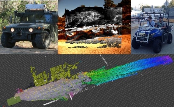 |
The LS3 perception system uses visible and infrared sensors and scanning laser range finders to permit day/night operation in a wide range of environments. Part of a DARPA project to create a legged robot that could function autonomously as a packhorse for a squad of soldiers, LS3 system capabilities include local terrain mapping and dynamic obstacle detection and tracking. The local terrain-mapping module builds a high-resolution map of nearby terrain that is used to guide gait selection and foot planting and that remains centered on the vehicle as it moves through the world. The local terrain-classification algorithms identify negative obstacles, water, and vegetation. The dynamic obstacle module allows LS3 to detect and track pedestrians near the robot, thereby ensuring vehicle safety when operating in close proximity with soldiers and civilians. After five years of development (1999-2014), LS3 is mature enough to operate with Marines in a realistic combat exercise.
| 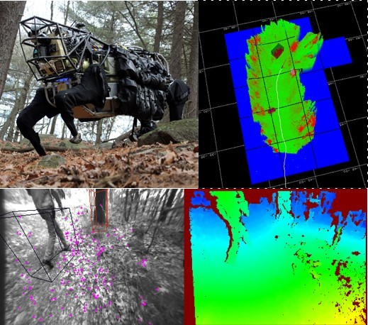 |
Project Tango envisions a future in which everyday mobile devices estimate their position with up to millimeter accuracy by building a detailed 3D map, just as GPS is used today. 3D mapping and robust, vision-based real-time navigation have been major challenges for robotics and computer vision, but recent advancements in computing power address these challenges by enabling the implementation of 3D pose estimation and map building in a mobile device equipped with a stereo camera pair. In collaboration with Google, JPL has demonstrated accurate and consistent 3D mapping that includes constructing detailed, textured models of indoor spaces in real time on memory-constrained systems.
| 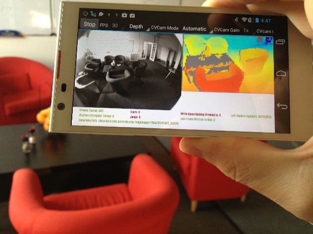 |
The Contact Detection and Analysis System (CDAS) processes camera images (both visible and IR spectra) for 360-degree maritime situational awareness. This capability is required to navigate safely among other vessels; it also supports mission operations such as automated target recognition, intelligence, surveillance, and reconnaissance in challenging scenarios—low-visibility weather conditions, littoral and riverine environments with heavy clutter, higher sea states, high-speed own-ship and contact motion, and semi-submerged hazards. The CDAS software fuses input from the JPL 360-degree camera head and the JPL Hammerhead stereo system for robust contact detection. Contacts are then tracked to build velocity estimates for motion planning and vessel type classification.
| 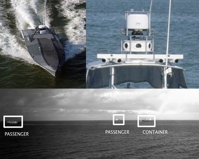 |
| ARES-V is a collaborative stereo vision technology for small aerial vehicles that enables instantaneous 3D terrain reconstruction with adjustable resolution. This technology can be used for robust surface-relative navigation, high-resolution mapping, and moving target detection. ARES-V employs two small quadrotors flying in a tandem formation to demonstrate adaptive resolution stereo vision. The accuracy of the reconstruction, which depends on the distance between the vehicles and the altitude, is adjustable during flight based on the specific mission needs. Applications of this technology include aerial surveillance and target-relative navigation for small body missions. | 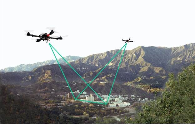 |
Path Planning
Fast Traverse enables fully autonomous rover navigation with a 100 percent driving duty cycle. Planetary rovers have traditionally been limited by the available computational power in space: When driving autonomously, the limited computation means that the rover must stop for a substantial period while the navigation software identifies a hazard-free path using acquired imagery. The resulting limitation on driving duty cycle reduces the rover’s average traverse rate; this in turn leads operators to prefer manual driving modes without the full suite of vision-based safety checks. Fast Traverse enables planetary rovers to drive faster, farther, and more safely by transitioning computation-intensive portions of autonomous navigation processing from the main CPU to a field-programmable gate array (FPGA) coprocessor. What would currently take many seconds or even minutes on state-of-the art radiation hard processors can be accomplished in microseconds using FPGA implementations. Fast Traverse technology has already been implemented, tested, and demonstrated on a research rover.
| 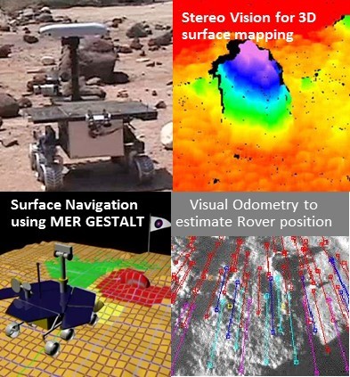 |
SUAVE could revolutionize the use of unmanned aerial vehicles (UAVs) for Earth science observations by automating the launch, retrieval, and data download process. SAUVE experiments with small, autonomous UAVs for in situ observation of ecosystem properties from leaf to canopy. These UAVs are able to conduct sorties many times per day for several months without human intervention, increasing the spatial resolution and temporal frequency of observations far beyond what could be achieved from traditional airborne and orbital platforms. This method also extends observations into locations and timescales that cannot be seen from traditional platforms, such as under tree canopies and continuous sensing throughout the diurnal cycle for months at a time. SAUVE could develop and demonstrate capabilities for autonomous landing and recharging, position estimation in-flight with poor GPS, and in-flight obstacle avoidance to enable unattended, long-duration, and repetitive observations.
| 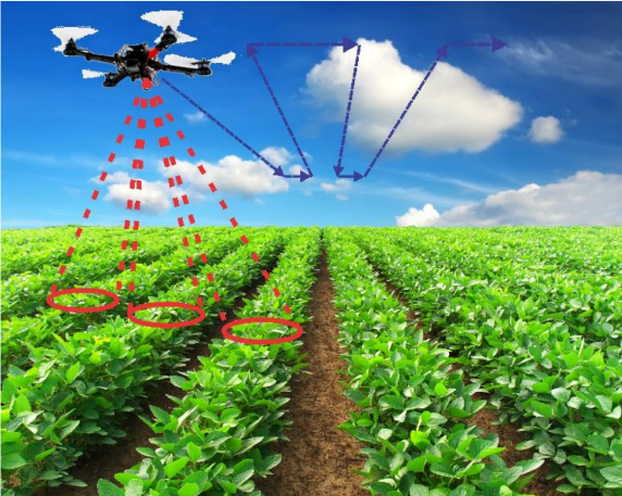 |
ACTUV, DARPA’s Anti-Submarine Warfare Continuous Trail Unmanned Vessel, is developing an independently deployed unmanned surface vessel optimized to provide continuous overt tracking of submarines. The program objective is to demonstrate the technical viability of an independently deployed unmanned naval vessel under sparse remote supervisory control robustly tracking quiet, modern diesel-electric submarines. SAIC is the prime for this DARPA contract. JPL is providing the autonomy capabilities of the ACTUV. In particular, JPL will support motion and mission planning and provide the health management capabilities for the robotic platform during its 75-day mission.
|  |
| AUV is an adaptive, long-duration autonomous in situ sensing system for an unmanned underwater vehicle with onboard autonomous capabilities for monitoring mixed layer variability and its relation to upper-ocean carbon cycles. AUV provides intelligent onboard autonomy to manage systems, self-adapt, and react to changing conditions related to mission objectives, resource constraints, and science opportunities in the environment. AUV also conducts onboard adaptive sampling algorithms to detect features of interest, follow relevant signatures, and adaptively build physical process models. AUV offers enhanced robotics and science exploration capabilities for marine environments at a reduced cost. | 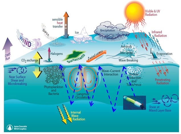 |
User Interface
| BioSleeve is a sleeve-based gesture recognition interface that can be worn in inside vehicle activity (IVA) and exovehicle activty (EVA) suits. BioSleeve incorporates electromyography and inertial sensors to provide intuitive force and position control signals from natural arm, hand, and finger movements. The goal of this effort is to construct a wearable BioSleeve prototype with embedded algorithms for adaptive gesture recognition. This could allow demonstration of control for a variety of robots, including surface rovers, manipulator arms, and exoskeletons. The final demonstration could simulate and assess gestural driving of the ISS Canadarm2 by an astronaut on EVA who is anchored to the arm’s end effector for station keeping. |  |
Other Robotics Technologies
Mars Heli is a proposed add-on to future Mars rovers that could potentially triple the distance these vehicles can drive in a Martian day while delivering a new level of visual information for choosing which sites to explore. This 1 kg platform (1 m blade span) can fly where rovers cannot drive, provide higher-resolution surface images than possible from orbit, and see much larger areas than possible with rover-mounted cameras. Mars Heli employs coaxial rotors designed for the thin Martian atmosphere (1% of Earth) and a radio link to the rover for relay to Earth. It has energy-absorbing, lightweight legs that provide for landing on natural terrain. A camera/IMU/altimeter is used for navigation and hazard detection, and a fault-tolerant computer provides autonomous aerial flight control and safe landings. Aerogel insulation and a heater keep the interior warm at night, and solar cells are used to recharge the battery. Testing with engineering prototypes has been done in a 25-foot vacuum chamber that replicates the atmosphere on Mars, allowing characterization of blade aerodynamics, lift generation, and flight control behaviors.
| 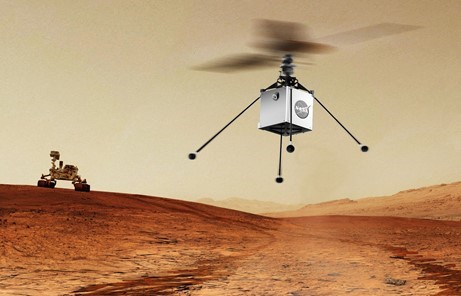 |
ISTAR is an in-space robotics technology and a telescope design concept featuring a limbed robot capable of assembling large telescopes in space. This could enable future space missions with telescopes of 10 m – 100 m aperture diameter size. Such large telescopes cannot be folded into a conventional rocket payload and, therefore, must instead be assembled in space from smaller components. ISTAR provides integrated robotics system concepts and matching telescope design concepts for a large space telescope mission, including lab demonstrations of telerobotics assembly in orbit.
| 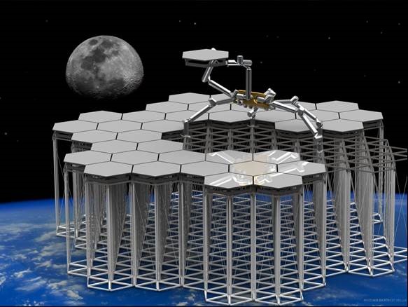 |
| IRIS is a robot that can grip the sides of spacecraft while performing tasks, enabling increased mobility and sustained operations on the surfaces of microgravity objects. The concept is to create a small (20 kg) robot characterized by a body with four limbs, each equipped with adhesively-anchoring grippers for surface mobility and thrusters for free flight. The IRIS effort specifically focuses on laying the technological groundwork for inspecting the ISS for micrometeorite damage. Using an airbearing table to simulate microgravity in two dimensions, the IRIS robot has demonstrated adhesively anchored walking, free flying using microthrusters, and transitional operations (takeoff and landing). The robot will carry a relevant contact inspection instrument and demonstrate the use of that instrument, including the generation of the adhesive reaction forces necessary for the use of the instrument. | 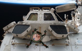 |
Cavebot is a gravity-agnostic mobility platform for any natural terrain. The robot uses hundreds of sharp claws called microspines that adapt to a surface independently to create secure anchor points. High-fidelity field experiments to test the robot’s mobility in caves in California and New Mexico have been conducted. Caves provide a chance to test the robot in all gravitational orientations for future missions to caves on Mars and the Moon, or for missions to asteroids, where a mobile robot could have to grip to the surface to avoid falling off. Microspine grippers were also tested successfully aboard NASA’s zero-g aircraft on multiple rock types, enabling the first ever zero-g drilling demonstration in 2014.
| 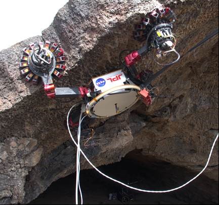 |
Hedgehog is a toss-hop-tumble spacecraft-rover hybrid robot concept for the exploration of small Solar System bodies. Multiple Hedgehogs can be deployed from a “mothership” onto the surface of a low-gravity object such as an asteroid. Using internal actuation to hop and tumble across the surface of a new frontier, Hedgehog is a minimalistic robotic platform for the in situ exploration of small bodies that has minimal complexity and is capable of large surface coverage as well as finely controlled regional mobility.
| 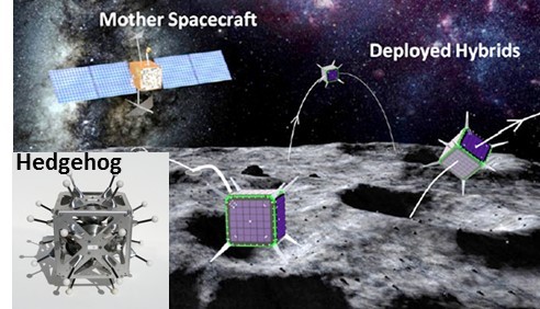 |
BRUIE is a two-wheeled robot capable of roving in an under-ice environment. The rover has positive buoyancy, allowing it to stick to the ice underside and operate using similar control principles as those used for traditional aboveground rovers. The system has been tested in thermokarst lakes near Barrow, Alaska, and data from onboard video and methane sensors gives scientific insight to the formation and distribution of trapped methane pockets in the lake ice.
| 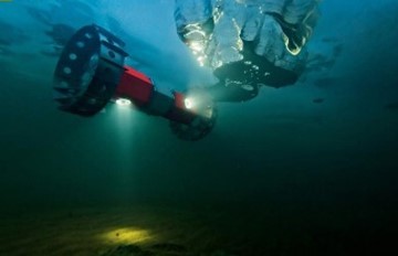 |
| Planetary balloons are buoyant vehicles that could fly for weeks or months in the planetary atmospheres of Venus and Titan, carrying a wide variety of science instruments and conducting extensive in situ investigations. The work done combines prototyping, testing, and analysis to mature the balloon technology for first use by NASA in a planetary mission. Planetary balloons are a direct extension of the balloon technology that has been used on Earth for the past two centuries. The main challenge is adapting the technology to the very different environments—Titan is cryogenically cold (85 to 95 K), and Venus has very high temperatures near the surface (460°C) and sulfuric acid clouds in the cool upper atmosphere (30°C). | 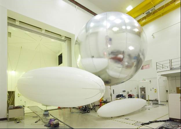 |
Precision Formation Flying
Many potential future astrophysical science missions, such as extrasolar terrestrial planet interferometer missions, X-ray interferometer missions, and optical/ultraviolet deep/space imagers would call for instrument apertures or baselines beyond the scope of even deployable structures. The only practical approach for providing the measurement capability required by the science community’s goals would be precision formation flying (PFF) of distributed instruments. Future missions, such as those for Earth observation and extrasolar planet hunting would require effective telescope apertures far larger than are practical to build. Instead, a suite of spacecraft, flying in formation and connected by high-speed communications could create a very large “virtual” science instrument. The advantage is that the virtual structure could be made to any size. For baselines more than about a dozen meters, precision formation flying becomes the only feasible option. This type of technology has been identified as critical for 21st Century NASA astrophysical and Earth science missions. Specifically, formation flying refers to a set of distributed spacecraft with the ability to interact and cooperate with each other. In deep space, formation flying would enable variable-baseline, interferometers that could probe the origin and structure of stars and galaxies with high precision. In addition, such interferometers would serve as essential instruments for discovering and imaging Earth-like planets orbiting other stars. Future Earth science missions would require PFF. Potential future Earth-science missions, such as terrestrial probe and observation missions would also benefit from PFF technologies. These missions would use PFF to simultaneously sample a volume of near-Earth space or create single-pass interferometric synthetic-aperture radars.
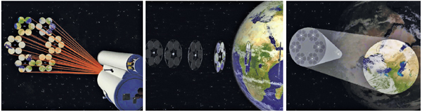
JPL’s Distributed Spacecraft Technology Program for Precision Formation Flying has developed architectures, methodologies, hardware and software components for precision control of collaborative distributed spacecraft systems, in order to enable these new mission architectures and their unprecedented science performance. These technologies ensure that JPL is uniquely poised to lead and collaborate on future missions.
Non-NASA applications of PFF include synthesized communication satellites for high-gain service to specific geographical regions, e.g., a particular area of operations, high-resolution ground-moving target indicator (ground- MTI) synthetic-aperture radars, and arrays of apertures for high-resolution surveillance of and from geosynchronous Earth orbit (GEO). Recently, the concept of fractionated spacecraft (FSC) has been introduced. An FSC system calls for functions of a monolithic spacecraft to be distributed over a cluster of separate spacecraft or modules. Each cluster element would perform a subset of functions, such as computation or power. FSC offers flexibility, risk diversification, and physical distribution of spacecraft modules to minimize system interactions that lead to system fragility. Flexibility would bes increased by the ability to add, replace, or reconfigure modules and thereby continually update an FSC’s architecture throughout its development and operational life. Further, FSC systems could be incrementally deployed and degrade gracefully. PFF would achieve the benefits of FSC, cluster sensing, guidance and control architectures and algorithms, and actuation that must be distributed across modules and coordinated through communication. Each type of PFF mission scenario creates unique technology needs. For astrophysical interferometry, inter-spacecraft range and bearing knowledge requirements are on the nanometer and subarcsecond levels, respectively.
Improved wide field-of-view (FOV) sensors and high-fidelity simulation tools are essential to operate such missions and to validate system performance prior to launch. Precision, centimeter-level drag-free control, repeat-track control, and formation control all would require micropropulsion systems. This would require high-bandwidth, and robust inter-spacecraft communication systems and distributed command and sensing designs to coordinate these complex precise formations. Even smaller missions of only two or three spacecraft must develop distributed command systems to avoid large, expensive mission operation teams. Finally, advanced formation guidance, estimation and control architectures and algorithms would be necessary for robust, fuel-optimal formation operation of any formation; for example, to perform reconfigurations for science targeting and to ensure collision avoidance.
Selected Research Thrusts
Many future Earth and deep-space missions that would achieve a host of measurement capabilities, both in the NASA and non-NASA communities, would be enabled by precision formation flying (PFF). Essential precision collaborative flight of distributed spacecraft systems would require PFF-critical technology developments ranging from architectures to methodologies, to hardware and software.
Distributed-Spacecraft Architectures
Distributed-spacecraft architectures are fundamentally different from single-spacecraft architectures. They require the combination of distributed sensor measurements, path planning, and control capabilities, subject to communication capacity to guarantee formation performance. Distributed architectures could enhance collision avoidance, allow for allocation and balancing of fuel consumption, and allow for graceful degradation in the case of system failure. New, scalable, and robust classes of distributed multi-spacecraft system architectures must be developed that integrate formation sensing, communication and control. To function as a formation, the spacecraft must be coupled through automatic control. Such control requires two elements: inter-spacecraft range and bearing information to determine the present formation configuration, and optimal desired trajectories that achieve science goals. These two elements are, respectively, formation estimation and formation guidance. All three capabilities—guidance, estimation, and control—must function in a distributed manner since precision performance requirements coupled with computational, scalability, and robustness constraints typically prevent any one spacecraft in a formation from having full formation knowledge in a timely manner. Distributed architectures determine how a formation is coordinated and, hence, the possible stability and performance characteristics achievable for given communication and sensing systems. As such, distributed architectures must be able to support a wide range of communication and sensing topologies and capabilities and further, must be able to adapt to changing topologies. Future performance targets include the development of architectures of up to 30 spacecraft with sub-centimeter performance over a 10-year mission life, with consistent graceful degradation while meeting sensor/communication requirements.
Wireless Data Transfer
High-throughput, low-latency, multipoint (cross-linking) communications with adaptable routing and robustness to fading is necessary to support formation-flying missions. Throughput and latency directly impact inter-spacecraft control and knowledge performance as well as payload operational efficiency. Real-time control quality of service must be maintained over large dynamic ranges, some latency, and varying number of spacecraft and formation geometries. Payloads would require tens to thousands of megabit-per-second data rates for target recognition/science-in-the-loop applications. Coordinating multiple spacecraft would require distributing locally available information (e.g., a local inter-spacecraft sensor measurement) throughout a formation. Health and high-level coordination information must also be disseminated, such as a spacecraft’s readiness to perform a certain maneuver. For these reasons, and unlike any single-spacecraft application, formations would require closing control loops over a distributed wireless data bus. For example, a sensor on one spacecraft might be used to control an actuator on another.
The overall precision performance of the formation can be limited by the ability of inter-spacecraft communications. While technologies such as cellular towers are fine for terrestrial voice applications, formations would require highly reliable systems free of single-point-failures and which would have high bandwidth and guaranteed low latency. Dropped packets could cause a synthesized instrument to stop functioning, severely reducing observational efficiency. Finally, the range over which formations operate means that the communication system must be capable of simultaneously talking to a spacecraft hundreds of kilometers away without deafening a spacecraft tens of meters away, a problem area referred to as cross-linking. Short-term performance targets for wireless data transfer for PFF would include operating 30 spacecraft at 100 Mbps data rates, with seamless network integration.
Formation Sensing and Control
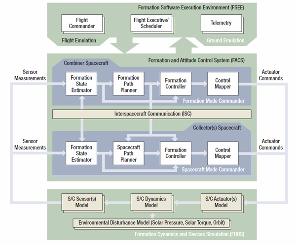
Formations would require inter-spacecraft knowledge to synthesize virtual structures for large instruments. Direct relative optical and radio frequency sensing of inter-spacecraft range and bearing would be essential, especially for deep space and GEO missions that cannot fully utilize global positioning system (GPS) capabilities. For astrophysical and exoplanet interferometry, the range and bearing knowledge between spacecraft must be sensed to the nanometer level for science and to the micrometer-to-millimeter level for precision formation control. Space-qualified, high-precision metrology systems with a large dynamic range and the ability to simultaneously track multiple neighboring spacecraft would be required. Further, variable lighting conditions and several orders-of-magnitude dynamic ranges must be accommodated, while maintaining reasonable mass/power/volume and ease of integration. Finally, beyond GPS, knowledge based on Deep Space Network (DSN) information would not be sufficient for formation spacecraft to find one another. So, the first step after deployment would be to initialize the formation: spacecraft must establish communication and search for each other with onboard formation sensors. The capability of sensors, particularly their field of view (FOV), would drive situational awareness within a formation and could enable attendant collision-avoidance capability. Sensors must provide relative knowledge from submeter/degree-to-micrometer/arcsecond level of range/ bearing performance to support robust science observations over operating distances of meters to tens of kilometers. For large formations, sensors must function with multiple spacecraft in FOV and minimal coupling to flight systems. For control, advanced formation guidance and estimation and control algorithms are necessary for robust, fuel-optimal formation operation, including reconfiguration and collision avoidance. The algorithms and methodologies are the low-level counterpart to the high-level distributed architectures.
Selected Research Projects
Balloons/Aerobots for Planetary Exploration
Balloons would offer unparalleled promise as vehicles of planetary exploration because they can fly low and cover large parts of the planetary surface. This research explores ways to predict and control the motion of balloons.
Tethers
Tethers would provide a unique capability to deploy, maintain, reconfigure, and retrieve any number of collaborative vehicles in orbit around any planet. Control techniques for tethered formation reconfiguration must allow the tethered spacecraft to act as a single unit, while the tether length could change depending on the mission profile. Tethers would also offer a high survivability low fuel alternative to scenarios in which multiple vehicles and light collectors must remain in close proximity for long periods of time. In this way, distributed tethered observatories with kilometer class apertures could be built that enable the resolution needed in the optical and microwave bands.
Ranging-MSTAR
Precision metrology system for state-determination and control of instruments on board distributed spacecraft missions.
The MSTAR task has developed a Modulation Sideband Technology for Absolute Ranging (MSTAR) sensor concept that enables absolute interferometric metrology. The concept is now being used to develop a two-dimensional precision metrology sensor. This technology would be applicable to any mission of scientific exploration in which there is a need for a precision sensor to be used for formation flying control of separated elements. The developed sensor may also find use in the lithography for semiconductor manufacturing and precision machining applications.
Survivable Systems for Extreme Environments
The environments encountered by Solar System in-situ exploration missions cover extremes of temperature, pressure, and radiation that far exceed the operational limits of conventional electronics, electronic packaging, thermal control, sensors, actuators, power sources and batteries. In these studies, environments are defined as “extreme” if they present extremes in pressure, temperature, radiation, and chemical or physical corrosion. In addition, certain proposed missions would experience extremes in heat flux and deceleration during their entry, descent and landing (EDL) phases, leading to their inclusion as missions in need of technologies for extreme environments.
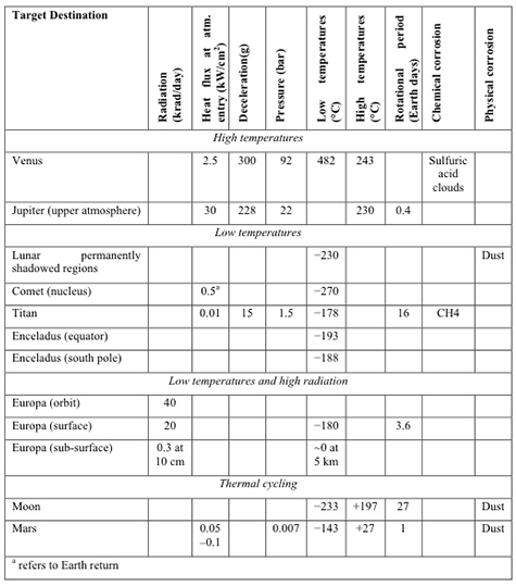
Specifically, a space mission environment is considered “extreme” if one or more of the following criteria are met:
- Heat flux: at atmospheric entry exceeding 1 kW/cm2 at atmospheric entry
- Hypervelocity impact: higher than 20 km/sec
- Low temperature: lower than -55°C
- High temperature: exceeding +125°C
- Thermal cycling: temperature extremes outside of the military standard range of -55°C to +125°C
- High pressures: exceeding 20 bars
- High radiation: total ionizing dose (TID) exceeding 300 krad (Si)
Additional extremes include:
- Deceleration (g-loading): exceeding 100 g
- Acidic environments: such as the sulfuric acid droplets in Venusian clouds
- Dusty environments: such as experienced on Mars
A summary of planetary destinations and their relevant – and sometimes coupled – extreme environments is shown in Table 1. Typically, high temperature and pressure conditions are coupled – e.g., for Venus in-situ mission concepts and proposed deep-entry probe missions to the two gas giants, Jupiter and Saturn. High radiation and low temperature can also be coupled, as experienced by missions to the Jovian system. Low temperatures could be associated with surface missions to the “Ocean Worlds,” the Moon, Mars, Titan, Triton, and comets. Thermal cycling would affect missions where the frequency of the diurnal cycle is relatively short, e.g., for Mars (with a similar cycle to Earth), and for the Moon (with 28 Earth days).
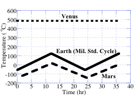
At one extreme, Venus lander missions would need to survive at 460 °C (730 K) temperatures and 90-bar pressures, and must pass through corrosive sulfuric acid clouds during descent (current technology limits the duration of Venus surface exploration to <2 hours). At the other extreme, ocean worlds, asteroids, comets, and Mars missions operate in extremely cold temperatures—in the range of -180 to -120 °C (~ 90-150 K). For missions to comets or close to the Sun, high-velocity impacts are a real concern, with impact velocities reaching greater than 500 km/second. Investments in technologies for developing these systems -- and for operations and survivability in extreme environments -- are continually emerging, and are crucial to the successful development of future NASA missions.
Spacecraft survival in these environments requires not only that mission designers test and model the effects, but also that they develop systems-level solutions, including: fault tolerance, thermal management, systems integration, and effects of four solar radii (perihelion for a solar-probe mission). For example, missions to Europa must survive radiation levels behind typical shielding thicknesses, combined with very low temperatures in the vicinity of -160 °C (~ 110 K). As recommended in the National Research Council’s most recent decadal survey on solar system exploration, New Frontiers in the Solar System: An Integrated Exploration Strategy, future missions may require operations in extreme environments at very high and very low temperatures, high and low pressures, corrosive atmospheres, or high radiation.
Current Challenges
Survival in High-Radiation Environments
Improvements in technology for possible missions to Europa, Titan, the Moon, and mid-Earth-orbit are crucial and are in development. Europa mission concepts (both lander and orbiter) present the challenge of surviving radiation levels behind typical shielding thicknesses. Significant research and development efforts to meet high-radiation challenges include test, analysis, and mitigation of single-event effects for complex processors and other integrated circuits at high device operating speeds. Total dose testing at high-dose and low-dose rates are being performed at high radiation levels to validate test methods for long-life missions. Tests and analysis of device performance in combined environments, total dose, displacement damage dose, and heavy ion dose must be performed to validate radiation effects models. The methodology used in the development of device performance data and worst-case scenario analysis is being developed to support reliable modeling and a realistic approach to system survival.
Survival in Particulate and Hypervelocity Impact Environments
An important consideration when building survivable systems is their reliability, extended functionality and operation in particulate environments. For example, lunar surface missions must operate in highly abrasive lunar dust, and all missions must penetrate orbital-debris fields. Potential impacts from meteoroids or Earth-based space debris at velocities in the range of 20–40 km/s short term and > 500 km/s long term (solar probe) are also an issue. JPL has developed a roadmap for mitigating impact environments—including debris, comets, and meteoroids—that includes modeling, testing, and shielding, as well as some of the leading models for dust environments.
Electronics and Mechanical Systems for Extreme Temperatures and Pressures Over Wide Temperature Ranges
Previous strategies in this area generally involved isolation of the spacecraft from the environment; however, isolation approaches can add substantially to weight, mass and power requirements. Environmentally tolerant technologies may provide better solutions, particularly in subsystems such as sensors, drilling mechanics, sample acquisition, and energy storage. In order to get the maximum science return, JPL is developing electronic and mechanical subsystems designed to survive temperature extremes. The challenges, outlined below, may be categorized into the following areas: low-temperature operation, high-temperature and high-pressure operation, and operations at wide temperature ranges.
Low-temperature operation
Several targeted missions and classes of mission concepts require the ability to function in extreme cold. These include missions to the Moon, Europa (lander only), deep-space missions (astrophysics and planet finding), and any mission requiring sample acquisition, as well as actuators or transmitters located on the exterior of any interplanetary spacecraft. Many of the currently available electronics will not perform in extremely cold environments. Additionally, many metals undergo brittle phase transitions with abrupt changes in properties, which are not well understood in these extreme cold environments. Other performance issues at cold temperatures include: the effects of combined low temperature and radiation; the reliability issues of field-effect transistors due to hot carriers; freeze-out of advanced complementary metal-oxide semiconductors at very cold temperatures; severe single-event effects at cold temperatures for silicon germanium semiconductors; and, battery operations at low temperatures.
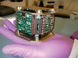
Low-temperature survivability is required for surface missions to Titan (-180 °C), Europa (-170 °C), Ocean Worlds such as Ganymede (-200 °C) and comets. Also, the Moon's equatorial regions experience wide temperature swings (from -180 °C to +130 °C during the lunar day/night cycle). The sustained temperature at the shadowed regions of lunar poles can be as low as -230 °C. Mars diurnal temperature changes from about -120 °C to +20 °C. Proposals are being developed for technologies that enable NASA to achieve scientific success on long duration missions to both low-temperature and wide-temperature range environments. Technologies of interest include:
- low-temperature, radiation-tolerant/radiation-hardened power electronics
- low-temperature-resistant, high strength-weight textiles for landing systems (parachutes, air bags)
- low-power and wide-operating-temperature, radiation-tolerant /radiation hardened RF electronics
- radiation-tolerant/radiation-hardened low-power/ultra-low-power, wide-operating-temperature, low-noise, mixed-signal electronics for space-borne systems, such as guidance and navigation avionics and instruments
- low-temperature, radiation-tolerant/radiation-hardened high-speed fiber optic transceivers
- low-temperature and thermal-cycle-resistant radiation-tolerant/radiation-hardened electronic packaging (including shielding, passives, connectors, wiring harness, and materials used in advanced electronics assembly)
- low- to medium-power actuators, gear boxes, lubricants and energy storage sources capable of operating across an ultra-wide temperature range (from -230 °C to 200 °C)
- Computer-Aided Design (CAD) tools for modeling and predicting the electrical performance, reliability, and life cycle for wide-temperature electronic/electro-mechanical systems and components
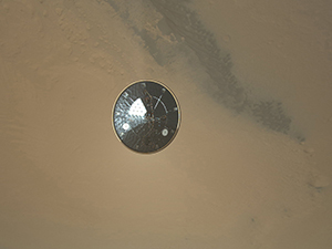
Research needs to continue to demonstrate technical feasibility (Phase I) and show a path toward a hardware/software demonstration (Phase II), and when possible, deliver a demonstration unit for functional and environmental testing at the completion of the Phase II contract.
High-temperature and high-pressure operation
To achieve successful long-term missions, previous Venus landers employed high-temperature pressure vessels with thermally protected electronics, which had a maximum surface lifetime of 127 minutes. Extending the operating range of electronic systems to the temperatures (485 °C, ~ 760 K) and pressures (90 bar) at the surface of Venus could significantly increase the science return of future missions. Toward that end, current work continues to develop an innovative sensor preamplifier capable of working in the Venus ground ambient and to be designed using commercial components (thermionic vacuum and solid-state devices; wide-band-gap, thick-film resistors; high-temperature ceramic capacitors; and monometallic interfaces). To identify commercial components and electronic packaging materials capable of operation within the specified environment, a series of active devices, passive components, and packaging materials was screened for operability at 500 °C (~ 775 K), targeting a tenfold increase in mission lifetime. The technology developed could also be used for Jupiter deep-atmosphere probes, which could reach pressures of up to 100 bars at temperatures of 450 °C (~ 725 K).
Survivability and operation of electronic systems in extreme environments are critical to the success of future NASA missions. Mission requirements for planets such as Venus cover the extremes of the temperature spectrum, greatly exceeding the rated limits of operation and survival of current commercially available military- and space-rated electronics, electronic packaging and sensors. In addition, distributed electronics for future mission concepts are rapidly being developed.
Operations at wide temperature ranges
Both lunar and Mars missions involve extreme temperature cycling. In the case of Mars, diurnal temperatures may vary from -130 to +20 °C (143-293 K), with a cycle approximately every 25 hours. For an extended mission, this translates into thousands of cycles. Lunar extremes are even greater (-230 to +130 °C, ~ 40-400 K) but with a cycle every month. Such extreme cases involve not only extreme temperatures but also fatigue issues not generally encountered in commercial, military, or space applications.
Reliability of Systems for Extended Lifetimes
Survivable systems need to have extensive reliability for extended lifetimes. Electronics are generally not designed to be functional for more than 10 years, unless specially fabricated for long life. Long-life systems ultimately need a 20-year (or greater) lifetime and are critical for extended lunar-stay missions, deep- and interstellar-space missions, and some Earth-orbiting missions.
Space Radiation Modeling
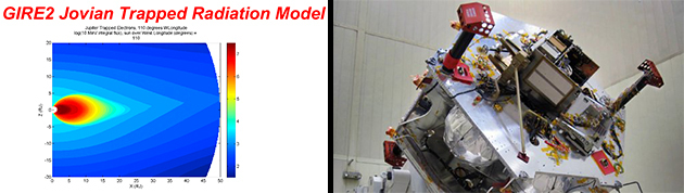
Right Image: Armored spacecraft workers place the special radiation vault for NASA's Juno spacecraft onto the propulsion module. Juno's radiation vault has titanium walls to protect the spacecraft's electronics from Jupiter's harsh radiation environment. Credit: NASA/Lockheed Martin.
The modeling of radiation environments is another important aspect of extreme environments technology. Extensive models have been developed for both the Jovian and Saturnian environments. Measurements of the high-energy, omnidirectional electron environment were used to develop a new model of Jupiter’s trapped electron radiation in the Jovian equatorial plane. This omnidirectional equatorial model was combined with components of the original Divine model of Jovian electron radiation to yield estimates of the out-of-plane radiation environment, referred to as the Galileo Interim Radiation Electron (GIRE) model. The GIRE model was then used to calculate a proposed Europa mission dose for an average and a 1-sigma worst-case scenario. While work remains to be done, the GIRE model represents a significant step forward in the study of the Jovian radiation environment, and provides a valuable tool for estimating and designing for that environment for future space missions.
Saturn's radiation belts have not received as much attention as the Jovian radiation belts because they are not nearly as intense; Saturn's famous particle rings tend to deplete the belts near where their peak would occur. As a result, there has not been a systematic development of engineering models of Saturn's radiation environment for mission design, with the exception of the (1990) Divine study that used published data from several charged-particle experiments from several flybys of Saturn to generate numerical models for the electron and proton radiation belts. However, Divine never formally developed a computer program that could be used for general mission analyses.
JPL has attempted to fill that void by developing the Saturn Radiation Model (SATRAD), which is a software version of the Divine model that can be used as a design tool for possible future missions to Saturn. Extension and refinement of these models are critical to future missions to Europa and Titan, as well as for extended Jovian missions.
H . XO Planetary Sciences
Planetary scientists work to improve our understanding of the planets, satellites and smaller bodies in the solar system. By studying the atmospheres, surfaces and interiors of planets, researchers can get clues to the origins and mechanics of our own home planet. Examples of these studies focus on understanding the origins of planets, using radar to determine the physical characteristics of asteroids, and searching for asteroids that may pose a hazard to Earth. Research is carried out in the laboratory, from astronomical facilities throughout the world, and from spacecraft and landers.
Asteroids, Comets, and Small Satellites

Small planetary body researchers at JPL study asteroids, comets, Kuiper Belt Objects (KBOs) and icy moons, using observations at ground-based telescopes, investigations in planetary geology, data analysis and interpretation, and theoretical modeling, while providing mission leadership and support. In addition, this field involves maintaining and exporting the past, current, and future positions for each of the eight planets in the Solar System, 181 natural satellites, and hundreds of thousands of comets, asteroids, and KBOs through the Solar System Dynamics Group. This group’s Horizons Ephemeris Export System has provided more than 190 million predictions from over one million different computers for Solar System object positions to an international community of scientists.
Selected Mission Projects and Research Efforts
Typical missions to asteroids, comets, moons, and KBOs include the following types of instruments:
- Imaging system
- IR Spectrometer and UV Spectrometer
- Lidar
- X-Ray Spectrometer, Gamma Ray Spectrometer, Alpha/X-ray Spectrometer
- Impact dust mass spectrometer
- Magnetometer
- Plasma Package
JPL small body investigators have played key leadership roles for many missions, including Voyager, Cassini-Huygens, Deep Space 1, Stardust, New Horizons, Near Earth Asteroid Rendezvous, Rosetta, Dawn, Hayabusa-1, Deep Impact, EPOXI, WISE, and NEOWISE. Many JPL researchers have obtained ground-based measurements in support of these and other NASA missions using assets such as the Palomar Mountain telescopes, NASA’s Infrared Telescope Facility, the Arecibo and Goldstone radio telescopes, and JPL’s Table Mountain Observatory.
Near Earth Object Program

Near-Earth Objects (NEOs) are comets and asteroids that have been nudged by the gravitational attraction of nearby planets into orbits that allow them to enter the Earth's neighborhood. Composed mostly of water ice and embedded dust particles, comets originally formed in the cold outer Solar System while most of the rocky asteroids formed in the warmer inner Solar System between the orbits of Mars and Jupiter. The scientific interest in comets and asteroids is due largely to the fact that they form the relatively unchanged remnant debris from the Solar System formation process some 4.6 billion years ago.
JPL’s Near-Earth Object Program is responsible for tracking the motions of NEOs that closely approach the Earth. In 2015 alone, near-Earth object telescopic observers supported by NASA have discovered more than 1,566 of these objects. The NEO Program Office continuously monitors the motions of these objects by improving knowledge of their orbits, identifying future Earth close approaches and, for objects of particular interest, computing Earth impact probabilities.
Radar Studies
Using the Arecibo Radio Telescope in Puerto Rico and the Deep Space Network, JPL manages one of the leading research programs in radar studies of NEOs. The aim is to understand the formation, evolution, morphology, composition, and dynamical properties of NEOs. These studies help describe the early conditions in the solar nebula and formation of the planets. Results of these studies also help characterize potential targets for future NASA missions.
Dawn
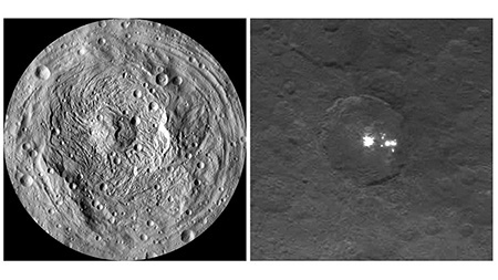
Dawn is the first mission to study Main Belt asteroids in great detail. The mission’s investigations have centered around two of the three protoplanets among the asteroids -- the rocky 4 Vesta and the carbonaceous, aqueously altered 1 Ceres. Launched in 2007, Dawn entered orbit around 4 Vesta in 2011 for a 14-month mission. The main goals of the investigation at Vesta were to characterize the geology and composition of the asteroid, and to understand its connections to the largest group of terrestrial meteorites, the basaltic achondrites. To this end, Dawn characterized a large impact basin at the South Pole of Vesta, the likely source of the meteorites. After a successful tour, Dawn left Vesta for a cruise trajectory and entered orbit around 1 Ceres in late 2012. Dawn discovered evaporate deposits in the floor of a large crater, suggesting that liquid may lie underneath its surface. Dawn will remain in orbit around Ceres.
NEOWISE
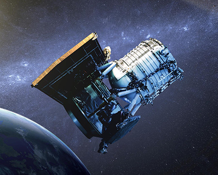
The Wide-field Infrared Survey Explorer (WISE) was a NASA telescope in a sun-synchronous orbit that ran out of its coolant, as planned, in October 2010. Prior to being put into hibernation in 2011, WISE conducted a program of searching for and characterizing NEOs. In August 2013, it was refurbished as a new mission, dubbed NEOWISE, with a dedicated goal of finding and studying NEOs. As of the beginning of 2016, WISE and NEOWISE have discovered 230 NEOs, 40 of which are Potentially Hazardous Objects that approach to within 0.05 AUs of Earth and are sufficiently large (~100 m in diameter) to cause massive devastation on the Earth should they impact. Twenty-five comets were also discovered. One of the major scientific results of the mission was that low-albedo carbonaceous asteroids are far more common among the NEO population than previously thought.
Rosetta
Rosetta is a European Space Agency mission to closely study and characterize Comet 67P/Churyumov-Gerassimenko through a perihelion passage. NASA contributed three instruments to the mission: the Microwave Instrument for the Rosetta Mission (MIRO), built and managed at JPL, the Alice ultraviolet spectrometer, and the Ion Electron Spectrometer (IES). JPL manages the NASA contributions to the Rosetta mission. In addition, numerous NASA-funded US Co-Investigators contributed to the European instruments on Rosetta.
Rosetta was launched in 2004, and rendezvoused with the comet in August 2014 for a detailed study of its nucleus, dust and ion coma, and its interaction with the solar wind. Its Philae probe was jettisoned from the spacecraft on November 12, 2014 in order to land on the surface of the comet. The lander’s instruments returned data for two days. Among the unexpected discoveries at the comet were molecular oxygen, a patchy distribution of water ice at its surface, a far more complex surface with cliffs, outgassing-pits, boulders, and a layered structure. Comet 67P is a nearly binary object, likely formed from two planetesimals.
Astrobiology

Astrobiology research at JPL is centered around understanding the potential of other bodies in the Solar System to support life. Researchers conduct field, laboratory, and theoretical studies in mineralogy, microbiology, geochemistry and organic and inorganic chemistry to help plan for future planetary exploration missions. JPL’s unique mix of science and engineering has fostered the participation of two JPL-led teams in the NASA Astrobiology Institute (NAI), a collaboration between multiple virtual institutes, during the previous five-year funding cycle (CAN 5; 2009-2014). One of the two JPL Teams studied the astrobiology of icy worlds, while the other focused on Saturn’s largest moon, Titan. The JPL Icy Worlds Team has been re-selected by NASA to continue for another five-year cycle (CAN 7, Principal Investigator: Dr. Isik Kanik; 2015-2020).
JPL Astrobiology focuses on planetary habitancy and habitability studies, and encompasses studies of the emergence of life at submarine alkaline hydrothermal vents and the nature of life in extreme environments. The pool of astrobiology researchers at JPL is an interdisciplinary-minded group of scientists, engineers, and technicians from the traditional fields of geology, microbiology, physics and chemistry, who now collaborate in this interdisciplinary field. JPL espouses a scientific method that takes a systems approach to astrobiology: integration of field, theoretical and laboratory work, and inclusion of those results into instrument development pertinent to answering mission science questions.
Selected Current Projects
Mars Science Laboratory (MSL) and Mars Exploration Rovers (MER)
The Mars Science Laboratory rover, Curiosity, and the long-lived Mars Exploration Rover Opportunity, are part of NASA's Mars Exploration Program, a long-term robotic exploration effort at the Red Planet. Curiosity was designed to help us understand the planet's past and present habitability – to assess whether Mars ever was, or is still today, an environment able to support microbial life.
Analysis by Curiosity’s mineralogical and chemistry instruments (named CHEMIN and SAM) of the first rock drilled by the rover tell of a history in which Mars could have supported microbial life. This sample contains clay minerals that could only have formed in slightly salty water that was neither too acidic nor too alkaline for life. Curiosity’s investigation of an ancient streambed displaying conglomerate rocks with embedded gravels provides compelling evidence of persistent water flow across the surface in Mars’ distant past.
On the other side of Mars, the 12-year-old Opportunity rover continues to discover new clues about habitable environments on ancient Mars. Recent analysis of a target (rock) named “Esperance” indicates the presence of clay-bearing materials with a composition that is higher in aluminum and silica and lower in calcium and iron than has been seen elsewhere on the planet. This is strongly suggestive of clement, mildly acidic conditions, and a reducing (not oxidizing) environment.
NASA Astrobiology Institute
Many JPL researchers collaborate or have joint appointments with NASA’s Astrobiology Institute led by JPL-based principal investigator Isik Kanik. This team performs in-depth studies of icy worlds of the Solar System (such as Europa and Enceladus) to answer questions related to the emergence, evolution, distribution, and future of life on Earth and elsewhere in the Universe.
Research and Development Efforts
In-situ capability for astrobiology investigations on Earth and on other planetary bodies
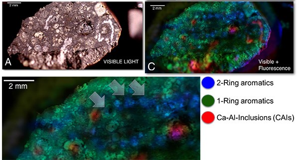
JPL has used a combination of NASA-funded research tasks and internal research and development funds to develop instrumentation for astrobiology studies. This research includes identification of biochemical & microbial populations that are present in the surface and subsurface, in extreme environments such as dry valleys and deep ocean bore holes in Antarctica, in evaporate lake beds (a Martian analog), and in laboratory-created simulated planetary environments including deep-sea hydrothermal vents. Our research funding comes from a variety of NASA and JPL programs, primarily from the NASA Astrobiology Institute (Icy Worlds), and from other NASA programs including:
- Planetary Instrument Concepts for the Advancement of Solar System Observations (PICASSO)
- Maturation of Instruments for Solar System Exploration (MatISSE)
- Planetary Science and Technology from Analog Research (PSTAR)
- Exobiology and Evolutionary Biology
- NASA Mars 2020 Instrument Development Program
- Flight instrument teams (Mars 2020 PIXL and SHERLOC)
- JPL Research and Technology Development
These developments could lead to new science discoveries that can enable future planetary exploration missions.
Paradigm shift in Emergence of Life Theory in Astrobiology at JPL
Nonequilibrium thermodynamic approaches to the emergence of life and the discovery of submarine alkaline hydrothermal vents in the Atlantic Ocean strongly support a theory being developed at JPL. This theory predicts that life would emerge on certain wet and rocky worlds as a response to the disequilibrium between their electron-rich interiors and their relatively oxidized exteriors, viz., between hydrothermal hydrogen emanating from the electron-rich interior and carbon dioxide in the oceans, and provides a basis for astrobiological exploration. The three recent covers of Astrobiology shown below, the first from the JPL group, signifies the paradigm shift.
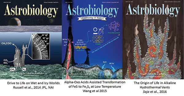
Planetary Atmospheres
Areas of Expertise
Core competencies in the area of planetary and exoplanetary atmospheric research at JPL include:
- Radiative transfer theory and remote sensing
- Atmospheric chemistry and composition, dynamics, structure, optics, and evolution
- Atmospheric process numerical modeling
- Atmospheric data analysis
- Image processing and scientific visualization
Selected Current Missions
JPL researchers in planetary and exoplanetary atmospheres are actively involved in space missions planned for, or in operation in, the Solar System:
Inner Solar System
- Mars Science Laboratory
- Mars Reconnaissance Orbiter
- Lunar Reconnaissance Orbiter
- InSight
- Mars 2020
- ExoMars
Outer Solar System
- Cassini
- Juno
- Rosetta
Recently published work covers Venus, Earth, Mars, Jupiter, Saturn, Uranus, Neptune, outer planetary satellites and planetary rings, surface-bound exospheres, comets, asteroids, and exoplanetary atmospheres.
Selected Research and Development Efforts
Modeling the Atmospheres of Earth-Like Extrasolar Planets
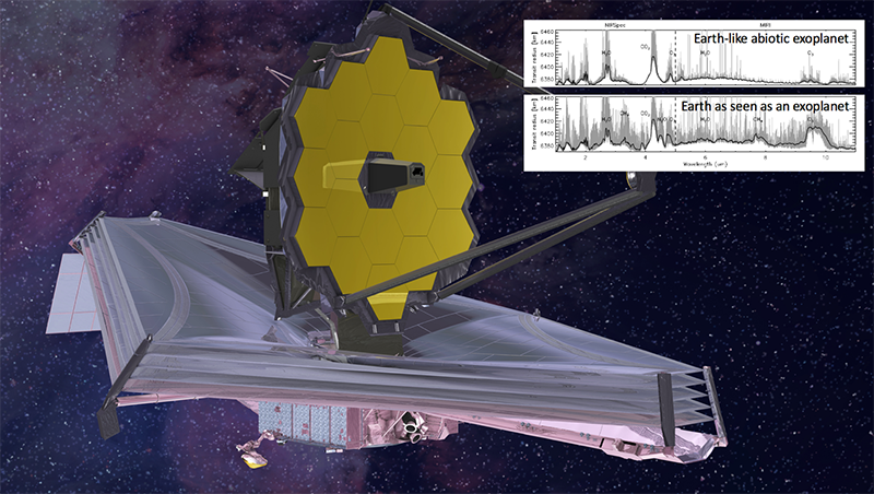
Nearly 2000 planets outside of our Solar System have been discovered to date, and new telescopes on Earth and in space could allow us to find and characterize even more exoplanets. Future observations from telescopes and other instruments such as by the James Webb Space Telescope (JWST), could focus on Earth-like exoplanets as they are the strongest candidates to harbor life as we know it. An important indicator for life is the existence of oxygen, and its photochemical byproduct ozone, in an exoplanet’s atmosphere. However, abiotic (devoid of life) processes also can produce oxygen and ozone. Scientists at JPL use computer models to simulate possible temperature structures and compositions of exoplanetary atmospheres and quantify the abiotic production of oxygen and ozone. The results are used to calculate spectra as they would be observed by JWST in order to evaluate the detectability of atmospheric constituents, helping to avoid ‘false positive’ detections of life in exoplanet observations.
Comets and the Origin of the Solar System
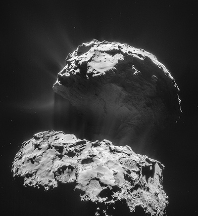
JPL designed, built, and operated a small radio telescope called MIRO (Microwave Instrument for the Rosetta Orbiter) aboard the European Space Agency’s Rosetta mission to a comet, and leads the international team of scientists interpreting the data. The Rosetta spacecraft was launched in 2004, spent 10 years getting to its primary target, and spent two years at comet 67P/Churyumov-Gerasimenko, or "CG" for short.
A comet has three main components: a solid nucleus made up of a mixture of ice, rock and organic compounds; a gaseous coma surrounding the nucleus, formed from the nucleus ices sublimating to gas; and dust (plus larger chunks) in the coma, which are solid particles lifted off the surface by the escaping gas. MIRO will use radio waves to study all three components, and how they interact, until the end of the Rosetta mission in 2016. Scientists hope to learn how comets formed, what they are made of, and how they evolve over time. MIRO has been mapping the amount of gas and dust coming from various parts of the nucleus, and the temperature and velocity of the gases as they move into the coma. Working with scientists using all the other instruments on Rosetta, as well as the instruments that were aboard the Philae lander (which Rosetta deployed onto the surface of the comet in November 2014), researchers at JPL are learning about how our solar system formed and what processes created the wonderfully bizarre surface of Comet CG.
Planetary Geology and Geophysics
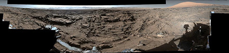
Planetary science, geophysics, and geosciences studies at JPL focus on the solid bodies of the Solar System, with particular emphasis on terrestrial-like planets and major satellites. Research topics
- tectonics
- volcanology
- impact processes
- geologic mapping
- surface geochemistry, mineralogy, and morphology
- interior structure
- lithosphere and mantle dynamics
- gravity and magnetic field interpretation
Selected Research Tasks
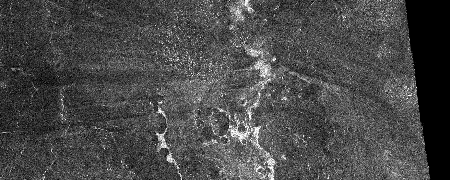
The planetary bodies at the center of most studies include Mars, Earth, Venus, Moon, Io, Europa, Titan, Vesta and Ceres. These bodies are studied using several methods including image interpretation (visible, infrared, radar), laboratory work, field work, infrared spectroscopy, geophysical data interpretation, modeling and laboratory work.
Research efforts originate from a variety of NASA and JPL programs, including:
- Mars Data Analysis
- Solar Systems Working
- Emerging Worlds
- Habitable Worlds
- Planetary Data Archiving, Restoration, and Tools
- Lunar, Mars, Cassini Data Analysis
- Flight instrument teams
- JPL Research and Technology Development
Radio Science
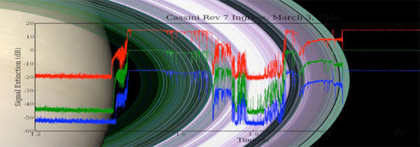
Radio links between spacecraft and Earth are utilized to examine changes in the characteristics of electromagnetic waves, such as their phase/frequency, amplitude, radio spectrum, or polarization, to investigate many aspects of planetary science, space physics and fundamental physics.
Selected Research Areas
Radio Occultations | |
A planetary body’s atmospheric composition, temperature, pressure, and ionospheric composition can be determined by tracking a spacecraft as it passes behind it.
As a spacecraft’s signal propagates through a ring system, it can reveal information on the particle size and distribution of the rings.
Some recent opportunities and discoveries achieved using radio occultation:
|  |
Gravity Field Determination & Celestial Mechanics | |
Careful tracking of the Doppler shift of a spacecraft's radio transmissions yields information about planetary gravitational fields, shapes, masses, and ephemerides.
Recent opportunities and discoveries:
| 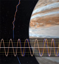 |
Bistatic Scattering | |
This technique uses a spacecraft's antenna to point at a specific point on a planetary body (called the specular reflection point). The the reflected signal is received at the Deep Space Network, and is analyzed to reveal details about the roughness and composition of the surface.
Recent opportunities and discoveries:
| 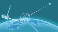 |
Doppler Wind Experiments | |
During the descent of a probe into a planetary atmosphere, the wind affects its trajectory, causing a Doppler shift on the transmitted signal. This effect can be detected by the Deep Space Network on Earth. Analysis of the received data reveals the wind speed and direction in the atmosphere at the probe's location.
Recent opportunities and discoveries:
| 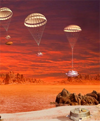 |
Solar Corona Characterization | |
As a spacecraft passes near the Sun during solar conjunction, the transmitted signal is altered by charged particles emitted from the solar corona. An analysis of electron content in the received signal can help characterize the solar corona.
| 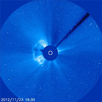 |
Tests of Fundamental Physics | |
Some spacecraft have radio equipment sensitive enough to enable the search for gravitational waves. This data can provide validation of the Theory of Relativity through estimation of post-Newtonian parameters using relativistic time-delay.
Recent opportunities and discoveries:
| 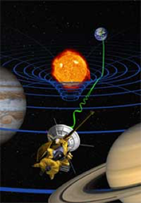 |
Critical Events, Engineering & Research | |
At JPL, the Raio Science Systems Group also supports mission critical events, such as Entry, Descent, and Landing (EDL), orbit insertion, and spacecraft launch and recovery, looking for changes in the signal transmitted to determine the state of the spacecraft.
Recent opportunities and discoveries:
| |
Solar System Ices and Icy Bodies
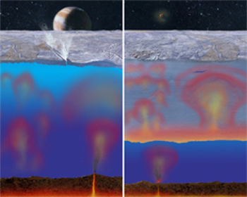
Ices are found in numerous locations in the universe and play a key role in the chemistry, physics and evolution of bodies within planetary systems. Researchers in this area represent a diverse range of backgrounds and expertise focused on investigating the whole range of ices in the solar system. There is a strong focus on the icy moons of Jupiter and Saturn, such as Europa, Ganymede, Enceladus, Titan, and Triton. Also of interest are comets, Kuiper Belt Objects (KBOs), NEOs and asteroids, and the polar regions of Mars. Research in this field contributes to our understanding the formation and evolution of icy bodies and the Solar System as a whole.
Selected Research Efforts
Thermophysical, Rheological and Mechanical Measurements of Icy Compositions with Application to Solar System Ices
The purpose of this research project is to experimentally determine the thermophysical, rheological, and mechanical properties of icy materials (ices and candidate cryolavas) over cryogenic temperatures (between 80 K and 300 K), which are applicable to outer Solar System objects such as the satellites of Jupiter and Saturn, as well as the Martian polar caps and terrestrial ice sheets. The thermophysical, dynamical, and geological evolution of these satellites were modelled using these material properties in support of the following science objectives: (1) to model the geophysical response of icy satellites to tidal excitation; and (2) to model the geological processes of icy satellites. The research strives to understand the evolutionary history of planetary ices, in terms of the geophysical and geologic processes that have occurred in icy worlds around the solar system.
Physical Chemistry of Planetary Ices
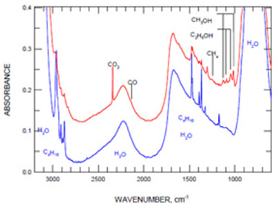
The outer Solar System is populated by ice-rich bodies: comets, Kuiper Belt Objects, centaurs, primitive asteroids, and icy planetary satellites. The research objective of the ‘Physical Chemistry of Planetary Ices’ project is to study and develop an understanding of the physical chemistry of ices of the outer Solar System.
The bulk surface icy composition of the satellites of the outer planets is predominantly water ice, with small amounts of co-condensed simple molecules such as NH3, CO2, CO, N2 and CH4, depending upon their condensation distance from the Sun in the primordial solar nebula. The outer surfaces of these satellites respond to particle and photon bombardment from the Sun, the solar wind, and charged particles trapped in local planetary magnetospheres, and undergo thermal cycling. The focus is on larger bodies of the outer Solar System such as the Jovian and Saturnian icy moons. Inorganic, organic and biological compounds may be present on/in surface ices. Such species could be delivered to icy surfaces through meteoric impacts or, on bodies such as Europa and Enceladus, potentially through active chemistry in subsurface liquid water. Research at JPL investigates the temperature-dependent chemical pathways available to mixtures of ices and inorganic/organic compounds subjected to energetic stimuli relevant to the outer Solar System.
This investigation includes a series laboratory experiments designed to elucidate the physical chemistry within ices relevant to icy solar system objects. The basic experimental approach is to engineer ice analogs constrained by model predictions and observations of solar system ices (composition, temperature, phase, structure, etc.). Once formed, the ices are systematically and quantitatively subjected to thermal cycling, UV photon irradiation, electron irradiation, etc. A number of analytical methods are applied to unravel the chemical and physical changes occurring in the samples. The investigation addresses questions such as: What are the essential chemical/physical properties of ices under conditions relevant to outer Solar System ices? What kind of chemistry can occur in these ices? This project is providing precise, accurate, and quantitative descriptions of the physical chemistry that occurs in outer Solar System ice analogs. This work provides a solid foundation for ground-truth understanding of observations obtained by JPL/NASA missions such as Galileo ISS, UVS, NIMS & Cassini ISS, VIMS and UVIS observations, and by ground-based facilities including Palomar Observatory, Table Mountain Observatory, NASA’s Infrared Telescope Facility, Arecibo, and Goldstone.
Radar Observations of Near-Earth Objects
Near-Earth Objects (NEOs) are asteroids or comets that approach or cross Earth’s orbit. They represent a potential hazard if they are both sufficiently large and on a path to impact Earth. JPL researchers have led efforts to discover and track NEOs, and are currently performing radar investigations of the properties of NEOs at radio telescopes in Arecibo, Puerto Rico, and at the Goldstone Deep Space Network in the Mojave Desert. These efforts are designed to understand the physical properties of NEOs such as their composition, roughness, size and gross structure, mechanical strength, dynamical properties, and surface texture. Many binary NEO systems have also been discovered with radar images. Complementary studies on the optical spectra and rotational states of NEOs are performed at Palomar Mountain and Table Mountain Observatory by JPL scientists. A better understanding of the nature of NEOs reveals their origins, collisional history, and the conditions under which they formed. Radar studies are also key for characterizing these bodies for further exploration by robotic spacecraft, including in situ samplers, and by astronauts.
Cryosphere Science
Scientists i
n the cryospheric sciences focus on understanding the role of the polar regions in global climate and sea level. Researchers have made use of GRACE, QuikSCAT, Synthetic Aperture Radar, ICESAT, and new modeling techniques to track changes in the cryosphere.
n the cryospheric sciences focus on understanding the role of the polar regions in global climate and sea level. Researchers have made use of GRACE, QuikSCAT, Synthetic Aperture Radar, ICESAT, and new modeling techniques to track changes in the cryosphere.
Selected Research Topics
Sea Ice
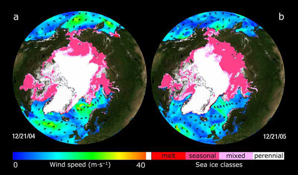
JPL’s QuikSCAT data -- combined with modeling software – have helped scientists track the loss of sea ice. In fact, they found a 23% loss in the extent of the Arctic’s sea ice cover in 2006 and 2007. More efforts in this field of study are focused on:
- Remote sensing observations (laser altimetry, passive microwave, scatterometry, radar interferometry)
- Seasonal and interannual changes in sea ice coverage and ice classes
- Heat, energy, and momentum exchanges at the surface
- Ice mechanics and dynamics
- Freshwater balance and impact on ocean circulation
- Numerically modelled sea ice propagation, fracture, and interaction with the ocean
- Mass balance of the Arctic and Southern Ocean sea ice covers
Ice Sheet and Glaciers
Ice sheet and glacier movements, and changes in the timing of high-latitude thaw over land, are very important indicators of climate change. Our specialty is to detect them from space, and correctly interpret the changes. Scientists at JPL also use a variety of other techniques to monitor many ice and glacial parameters:
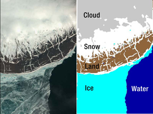
- Remote sensing observations of continental ice (radar interferometery, gravity, GPS, altimetry, microwave and optical)
- Mass balance of ice sheets and mountain glaciers
- Contributions to sea level change from glacier ice
- Snow accumulation and snowmelt
- Grounding line dynamics and stability of ice sheets
- Ice rheology
- Subglacial and englacial processes
- Ice-shelves/ocean interactions and impact on ocean circulation
- Numerical modeling of ice sheet evolution using data assimilation/control methods
Spring Thaw Monitoring
The Space Technology 6 Autonomous Scientific Experiment tracked changes in the Spring Thaw using new onboard software developed by JPL engineers, software which distinguishes among water, ice, and snow. Such studies continue a tradition of studies at JPL that found evidence for earlier regional thawing, at a rate of almost one day per year since 1988.
I.XO Terrestrial Time ( E E and T T )
E E ( Energy Elevation ) and T T ( Terrestrial Time )
for Saucer Tech Energy Input
Terrestrial Time (TT) is a modern astronomical time standard defined by the International Astronomical Union, primarily for time-measurements of astronomical observations made from the surface of Earth. For example, the Astronomical Almanac uses TT for its tables of positions (ephemerides) of the Sun, Moon and planets as seen from Earth. In this role, TT continues Terrestrial Dynamical Time (TDT or TD), which in turn succeeded ephemeris time (ET). TT shares the original purpose for which ET was designed, to be free of the irregularities in the rotation of Earth.
The unit of TT is the SI second, the definition of which is currently based on the caesium atomic clock, but TT is not itself defined by atomic clocks. It is a theoretical ideal, and real clocks can only approximate it.


TT is distinct from the time scale often used as a basis for civil purposes, Coordinated Universal Time (UTC). TT indirectly underlies UTC, via International Atomic Time (TAI). Because of the historical difference between TAI and ET when TT was introduced, TT is approximately 32.184 s ahead of TAI.
A definition of a terrestrial time standard was adopted by the International Astronomical Union (IAU) in 1976 at its XVI General Assembly, and later named Terrestrial Dynamical Time (TDT). It was the counterpart to Barycentric Dynamical Time (TDB), which was a time standard for Solar system ephemerides, to be based on a dynamical time scale. Both of these time standards turned out to be imperfectly defined. Doubts were also expressed about the meaning of 'dynamical' in the name TDT.
In 1991, in Recommendation IV of the XXI General Assembly, the IAU redefined TDT, also renaming it "Terrestrial Time". TT was formally defined in terms of Geocentric Coordinate Time (TCG), defined by the IAU on the same occasion. TT was defined to be a linear scaling of TCG, such that the unit of TT is the SI second on the geoid (Earth surface at mean sea level). This left the exact ratio between TT time and TCG time as something to be determined by experiment. Experimental determination of the gravitational potential at the geoid surface is a task in physical geodesy.
In 2000, the IAU very slightly altered the definition of TT by adopting an exact value for the ratio between TT and TCG time, as 1 − 6.969290134 × 10⁻¹⁰.[4] (As measured on the geoid surface, the rate of TCG is very slightly faster than that of TT, see below, Relativistic relationships of TT.)
Current definition

TT differs from Geocentric Coordinate Time (TCG) by a constant rate. Formally it is defined by the equation

where TT and TCG are linear counts of SI seconds in Terrestrial Time and Geocentric Coordinate Time respectively, LG is the constant difference in the rates of the two time scales, and E is a constant to resolve the epochs (see below). LG is defined as exactly 6.969290134 × 10⁻¹⁰. (In 1991 when TT was first defined, LG was to be determined by experiment, and the best available estimate was 6.969291 × 10⁻¹⁰.)
The equation linking TT and TCG is more commonly seen in the form

where JD TCG is the TCG time expressed as a Julian date (JD). This is just a transformation of the raw count of seconds represented by the variable TCG, so this form of the equation is needlessly complex. The use of a Julian Date specifies the epoch fully. The above equation is often given with the Julian Date 2443144.5 for the epoch, but that is inexact (though inappreciably so, because of the small size of the multiplier LG). The value 2443144.5003725 is exactly in accord with the definition.
Time coordinates on the TT and TCG scales are conventionally specified using traditional means of specifying days, carried over from non-uniform time standards based on the rotation of Earth. Specifically, both Julian Dates and the Gregorian calendar are used. For continuity with their predecessor Ephemeris Time (ET), TT and TCG were set to match ET at around Julian Date 2443144.5 (1977-01-01T00Z). More precisely, it was defined that TT instant 1977-01-01T00:00:32.184 exactly and TCG instant 1977-01-01T00:00:32.184 exactly correspond to the International Atomic Time (TAI) instant 1977-01-01T00:00:00.000 exactly. This is also the instant at which TAI introduced corrections for gravitational time dilation.
TT and TCG expressed as Julian Dates can be related precisely and most simply by the equation
- JDTT = EJD + (JDTCG − EJD) (1 − LG)
where EJD is 2443144.5003725 exactly.
Realization
TT is a theoretical ideal, not dependent on a particular realization. For practical purposes, TT must be realized by actual clocks in the Earth system.
The main realization of TT is supplied by TAI. The TAI service, running since 1958, attempts to match the rate of proper time on the geoid, using an ensemble of atomic clocks spread over the surface and low orbital space of Earth. TAI is canonically defined retrospectively, in monthly bulletins, in relation to the readings that particular groups of atomic clocks showed at the time. Estimates of TAI are also provided in real time by the institutions that operate the participating clocks. Because of the historical difference between TAI and ET when TT was introduced, the TAI realization of TT is defined thus:
- TT(TAI) = TAI + 32.184 s
Because TAI is never revised once published, it is possible for errors in it to become known and remain uncorrected. It is thus possible to produce a better realization of TT based on reanalysis of historical TAI data. The BIPM has done this approximately annually since 1992. These realizations of TT are named in the form "TT(BIPM08)", with the digits indicating the year of publication. They are published in the form of table of differences from TT(TAI). The latest as of February 2018 is TT(BIPM17).
The international communities of precision timekeeping, astronomy, and radio broadcasts have considered creating a new precision time scale based on observations of an ensemble of pulsars. This new pulsar time scale will serve as an independent means of computing TT, and it may eventually be useful to identify defects in TAI.
Approximation
Sometimes times described in TT must be handled in situations where TT's detailed theoretical properties are not significant. Where millisecond accuracy is enough (or more than enough), TT can be summarized in the following ways:
- To millisecond accuracy, TT runs parallel to the atomic timescale (International Atomic Time, TAI) maintained by the BIPM. TT is ahead of TAI, and can be approximated as TT ≅ TAI + 32.184 seconds. (The offset 32.184 s arises from the history.)
- TT also runs in parallel with the GPS time scale, which has a constant difference from atomic time (TAI − GPS time = +19 seconds), so that TT ≅ GPS time + 51.184 seconds.
- TT is in effect a continuation of (but is more precisely uniform than) the former Ephemeris Time (ET). It was designed for continuity with ET, and it runs at the rate of the SI second, which was itself derived from a calibration using the second of ET (see, under Ephemeris time, Redefinition of the second and Implementations.)
- TT runs a little ahead of UT1 (a refined measure of mean solar time at Greenwich) by an amount known as ΔT = TT − UT1. ΔT was measured at +67.6439 seconds (TT ahead of UT1) at 0h UTC on 1 January 2015; and by retrospective calculation, ΔT was close to zero around the year 1900. The difference ΔT, though somewhat unpredictable in fine detail, is expected to continue to increase, with UT1 becoming steadily (but irregularly) further behind TT in the future.
Relativistic relationships
Observers in different locations, that are in relative motion or at different altitudes, can disagree about the rates of each other's clocks, owing to effects described by the theory of relativity. As a result, TT (even as a theoretical ideal) does not match the proper time of all observers.
In relativistic terms, TT is described as the proper time of a clock located on the geoid (essentially mean sea level). However, TT is now actually defined as a coordinate time scale.[12] The redefinition did not quantitatively change TT, but rather made the existing definition more precise. In effect it defined the geoid (mean sea level) in terms of a particular level of gravitational time dilation relative to a notional observer located at infinitely high altitude.
The present definition of TT is a linear scaling of Geocentric Coordinate Time (TCG), which is the proper time of a notional observer who is infinitely far away (so not affected by gravitational time dilation) and at rest relative to Earth. TCG is used so far mainly for theoretical purposes in astronomy. From the point of view of an observer on Earth's surface the second of TCG passes in slightly less than the observer's SI second. The comparison of the observer's clock against TT depends on the observer's altitude: they will match on the geoid, and clocks at higher altitude tick slightly faster.
J. XO
Timing a Space Laser With a NASA- style Stopwatch
To time how long it takes a pulse of laser light to travel from space to Earth and back, you need a really good stopwatch — one that can measure within a fraction of a billionth of a second.


That kind of timer is exactly what engineers have built at NASA’s Goddard Space Flight Center in Greenbelt, Maryland, for the Ice, Cloud and land Elevation Satellite-2. ICESat-2, scheduled to launch in 2018, will use six green laser beams to measure height. With its incredibly precise time measurements, scientists can calculate the distance between the satellite and Earth below, and from there record precise height measurements of sea ice, glaciers, ice sheets, forests and the rest of the planet’s surfaces.
"Light moves really, really fast, and if you’re going to use it to measure something to a couple of centimeters, you’d better have a really, really good clock,"
Deputy Systems Engineer Phil Luers explains how ICESat-2’s ATLAS instrument transmitter and receiver subsystems come together to calculate the timing of photons, which, in turn, measure the elevation of ice.
If its stopwatch kept time even to a highly accurate millionth of a second, ICESat-2 could only measure elevation to within about 500 feet. Scientists wouldn’t be able to tell the top of a five-story building from the bottom. That doesn’t cut it when the goal is to record even subtle changes as ice sheets melt or sea ice thins.
To reach the needed precision of a fraction of a billionth of a second, Goddard engineers had to to develop and build their own series of clocks on the satellite’s instrument — the Advanced Topographic Laser Altimeter System, or ATLAS. This timing accuracy will allow researchers to measure heights to within about two inches.
"Calculating the elevation of the ice is all about time of flight," said Phil Luers, deputy instrument system engineer with the ATLAS instrument. ATLAS pulses beams of laser light to the ground and then records how long it takes each photon to return. This time, when combined with the speed of light, tells researchers how far the laser light traveled. This flight distance, combined with the knowledge of exactly where the satellite is in space, tells researchers the height of Earth’s surface below.


The stopwatch that measures flight time starts with each pulse of ATLAS’s laser. As billions of photons stream down to Earth, a few are directed to a start pulse detector that triggers the timer, Luers said.
Meanwhile, the satellite records where it is in space and what it’s orbiting over. With this information, ATLAS sets a rough window of when it expects photons to return to the satellite. Photons over Mount Everest will return sooner than photons over Death Valley, since there is less distance to travel.
The photons return to the instrument through the telescope receiver system and pass through filters that block everything that’s not the exact shade of the laser’s green, especially sunlight. The green ones make it through to a photon-counting electronics card, which stops the timer. Most of the photons that stop the timer will be reflected sunlight that just happens to be the same green. But by firing the laser 10,000 times a second the "true" laser photon returns will coalesce to give scientists data on surface elevation.
"If you know where the spacecraft is, and you know the time of flight so you know the distance to the ground, now you have the elevation of the ice," Luers said.
The timing clock itself consists of several parts to better keep track of time. There’s the GPS receiver, which ticks off every second — a coarse clock that tells time for the satellite. ATLAS features another clock, called an ultrastable oscillator, which counts off every 10 nanoseconds within those GPS-derived seconds.
"Between each pulse from the GPS, you get 100 million ticks from the ultrastable oscillator," Neumann said. "And it resets itself with the GPS every second."
Ten nanoseconds aren’t enough, though. To get down to even more precise timing, engineers have outfitted a fine-scale clock within each photon-counting electronic card. This subdivides those 10-nanosecond ticks even further, so that return time is measured to the hundreds of picoseconds.
Some adjustments to this travel time need to be made on the ground. Computer programs combine many photon travel-times to improve the precision. Programs also compensate for how long it takes to move through the fibers and wires of the ATLAS instrument, the impacts of temperature changes on electronics and more.


"We correct for all of those things to get to the best time of flight we possibly can calculate," Neumann said, allowing researchers to see the third dimension of Earth in detail.
++++++++++++++++++++++++++++++++++++++++++++++++++++++++++++++++++++++++
e- AMNI Government Space System on e- Space degree

++++++++++++++++++++++++++++++++++++++++++++++++++++++++++++++++++++++++
Tidak ada komentar:
Posting Komentar