Jumat, 02 Agustus 2019

Human Stem cells and the Phase of e- Locker Detector in we can call God's past copy AMNIMARJESLOW GOVERNMENT 91220017 S-Xi Pic 2020 - 2030 0209010014 LJBUSAGrowing ___ Thankyou for Lord Jesus to Saviour You and Me ___ Gen. Mac Tech Zone Human Stem Cells and e- Locker detector in to Point Virtual Matrix


               Hasil gambar untuk human stem cell pattern          Hasil gambar untuk usa flag stem cells


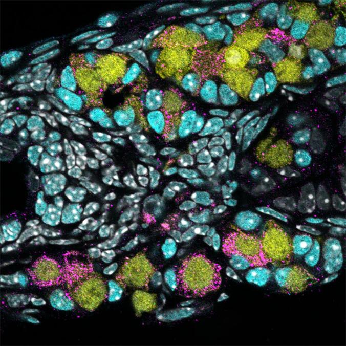
human stem cells is a place where the storage of human genetic memory where genes or human codes are made sequentially that form a tangible development of an organ of living things called humans, this human stem cell code can be taken during one week of fertilization between sperm cells and cells eggs and their shape are almost identical for all stem cells of living creatures other than humans. when humans were created by the Father in heaven, the code of the genetic code was revealed until now where humans can manifest according to their original form, namely when God formed the first human, at that time God formed from embryonic cells from the embryo composition from the existence of the new earth which he created itself in the form of similarities between the horizon, soil, dust and water as the initial embryo of the formation of the earth. God said that you were created in the same image and likened to me, and so the Lord Jesus always made a parable in the likeness and like, we were created in the same image and in the same way as our creator, and that means our mother cell was similar and similar. in this era we can call God's past copy so and if copy paste wants to be perfect with the creator of course we must continue to know him, so that we will be equal and perfect of course for the grace and affection of the creator, God himself. in the detection and processing of human embryos in today's era many use modern technology in the form of sophisticated electronic engineering techniques that are artificial intelligence, which is the second derivative of human thinking. if we call it in the complex electronic language that is the 2nd differential, we are the 1st differential from God who is the Father in heaven if we hear the diffraction means there is a matter of development time in the usual calculations in electronics called Timer For Up / down Counter or we are Real Word (up counter) and Retro (down Counter). 


                                                               Love in Second Save of Light  


                                                       Hasil gambar untuk human stem cell pattern


                                                    ( Gen . Mac Tech Zone Point Virtual Matrix  ) 


                                                     X O 11   stem cells


                                                Hasil gambar untuk human stem cell pattern

Cells in the body have specific purposes, but stem cells are cells that do not yet have a specific role and can become almost any cell that is required.
Stem cells are undifferentiated cells that can turn into specific cells, as the body needs them.
Scientists and doctors are interested in stem cells as they help to explain how some functions of the body work, and how they sometimes go wrong.


                                 Sources of stem cells


Stem cells originate from two main sources: adult body tissues and embryos. Scientists are also working on ways to develop stem cells from other cells, using genetic "reprogramming" techniques.

Adult stem cells
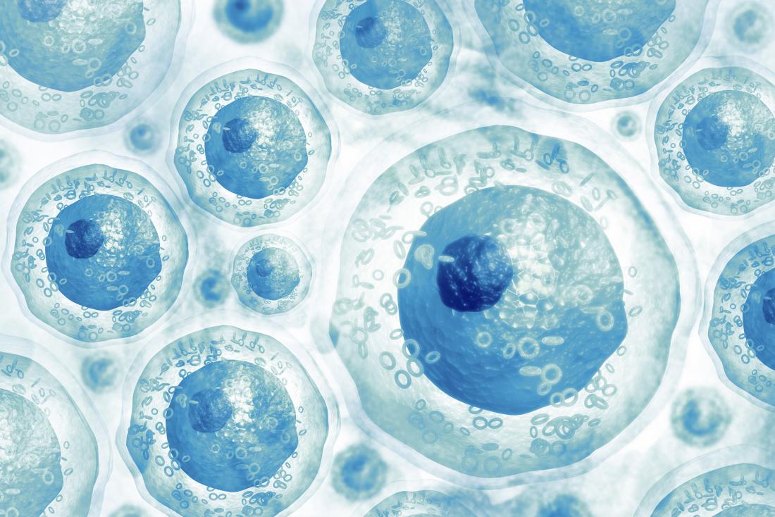
Stem cells
Stem cells can turn into any type of cell before they become differentiated.
A person's body contains stem cells throughout their life. The body can use these stem cells whenever it needs them.
Also called tissue-specific or somatic stem cells, adult stem cells exist throughout the body from the time an embryo develops.
The cells are in a non-specific state, but they are more specialized than embryonic stem cells. They remain in this state until the body needs them for a specific purpose, say, as skin or muscle cells.
Day-to-day living means the body is constantly renewing its tissues. In some parts of the body, such as the gut and bone marrow, stem cells regularly divide to produce new body tissues for maintenance and repair.
Stem cells are present inside different types of tissue. Scientists have found stem cells in tissues, including:
  • the brain
  • bone marrow
  • blood and blood vessels
  • skeletal muscles
  • skin
  • the liver
However, stem cells can be difficult to find. They can stay non-dividing and non-specific for years until the body summons them to repair or grow new tissue.
Adult stem cells can divide or self-renew indefinitely. This means they can generate various cell types from the originating organ or even regenerate the original organ, entirely.
This division and regeneration are how a skin wound heals, or how an organ such as the liver, for example, can repair itself after damage.
In the past, scientists believed adult stem cells could only differentiate based on their tissue of origin. However, some evidence now suggests that they can differentiate to become other cell types, as well.

Embryonic stem cells

From the very earliest stage of pregnancy, after the sperm fertilizes the egg, an embryo forms.
Around 3–5 days after a sperm fertilizes an egg, the embryo takes the form of a blastocyst or ball of cells.
The blastocyst contains stem cells and will later implant in the womb. Embryonic stem cells come from a blastocyst that is 4–5 days old.
When scientists take stem cells from embryos, these are usually extra embryos that result from in vitro fertilization (IVF).
In IVF clinics, the doctors fertilize several eggs in a test tube, to ensure that at least one survives. They will then implant a limited number of eggs to start a pregnancy.
When a sperm fertilizes an egg, these cells combine to form a single cell called a zygote.
This single-celled zygote then starts to divide, forming 2, 4, 8, 16 cells, and so on. Now it is an embryo.
Soon, and before the embryo implants in the uterus, this mass of around 150–200 cells is the blastocyst. The blastocyst consists of two parts:
  • an outer cell mass that becomes part of the placenta
  • an inner cell mass that will develop into the human body
The inner cell mass is where embryonic stem cells are found. Scientists call these totipotent cells. The term totipotent refer to the fact that they have total potential to develop into any cell in the body.
With the right stimulation, the cells can become blood cells, skin cells, and all the other cell types that a body needs.
In early pregnancy, the blastocyst stage continues for about 5 days before the embryo implants in the uterus, or womb. At this stage, stem cells begin to differentiate.
Embryonic stem cells can differentiate into more cell types than adult stem cells.

Mesenchymal stem cells (MSCs)

MSCs come from the connective tissue or stroma that surrounds the body's organs and other tissues.
Scientists have used MSCs to create new body tissues, such as bone, cartilage, and fat cells. They may one day play a role in solving a wide range of health problems.

Induced pluripotent stem cells (iPS)

Scientists create these in a lab, using skin cells and other tissue-specific cells. These cells behave in a similar way to embryonic stem cells, so they could be useful for developing a range of therapies.
However, more research and development is necessary.
To grow stem cells, scientists first extract samples from adult tissue or an embryo. They then place these cells in a controlled culture where they will divide and reproduce but not specialize further.
Stem cells that are dividing and reproducing in a controlled culture are called a stem-cell line.
Researchers manage and share stem-cell lines for different purposes. They can stimulate the stem cells to specialize in a particular way. This process is known as directed differentiation.  it has been easier to grow large numbers of embryonic stem cells than adult stem cells. However, scientists are making progress with both cell types.


                             Hasil gambar untuk human stem cell pattern


       X O 110  110   Stem Cells and the study of  Mathematics , Statistics and Physics 


Human stem cells are at the forefront of modern molecular biology research due to their ability to give rise to any specialist human cell type, a property known as pluripotency.  However, stem cells are notoriously hard to grow in culture.  Here we are developing mathematical models of the stem cell behaviour, from single or a few cells up to colonies of thousands. 
the last concept of "Dynamics of single human embryonic stem cells and their pairs: a quantitative analysis"  we performed real-time microscope imaging of human embryonic stem cells and analysed the kinematics of single and pairs of cells.  
We find that the cells, and their pairs, typically move like an isotropic random walk with a characteristic speed.  Here, we present a movie of the typical stem cell motion.


                   Hasil gambar untuk human stem cell pattern


                   Ecological Networks


An ecological network is a representation of the interactions between species in an ecosystem, a familiar example of which is the food web.  Recent advances in DNA sequencing techniques allow biologists to construct and describe such networks in unprecedented levels of detail.


we are interested in understanding the dynamics of species within complex ecological networks and predicting network responses to external perturbations. We must saving of  Biology with real-world ecological data sets. 


   X O 110  110  110  Data set in electronic circuit electron , we call Counter and frequency


In digital logic and computing, a counter is a device which stores (and sometimes displays) the number of times a particular event or process has occurred, often in relationship to a clock signal. ... A counter circuit is usually constructed of a number of flip-flops connected in cascade. 


Counter is a digital device and the output of the counter includes a predefined state based on the clock pulse applications. The output of the counter can be used to count the number of pulses. Generally, counters consist of a flip-flop ( memory ) arrangement which can be synchronous counter or asynchronous counter.

 Types of Counters, Binary Ripple Counter, Ring Counter, BCD Counter, Decade counter, Up down Counter, Frequency Counter

  
Hasil gambar untuk electronic circuit  counter 
                                                             Up - Counter

Counter is a sequential circuit. A digital circuit which is used for a counting pulses is known counter. Counter is the widest application of flip-flops. It is a group of flip-flops with a clock signal applied. 


The only difference is that for the up counter the output is taken at the non-inverting output ports of the flip-flops. Whereas, for the down counter the output is taken at the inverting output ports of the flip-flops. 


Counters are used in digital electronics for counting purpose, they can count specific event happening in the circuit. For example, in UP counter a counter increases count for every rising edge of clock. 

Counter means ;
1 : marked by or tending toward or in an opposite direction or effect. 2 : given to or marked by opposition, hostility, or antipathy. 3 : situated or lying opposite the counter side.  
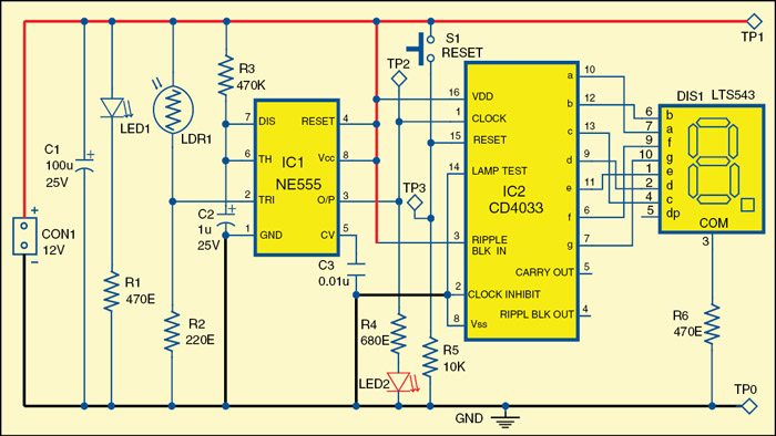
 
Hasil gambar untuk electronic circuit  counter

     
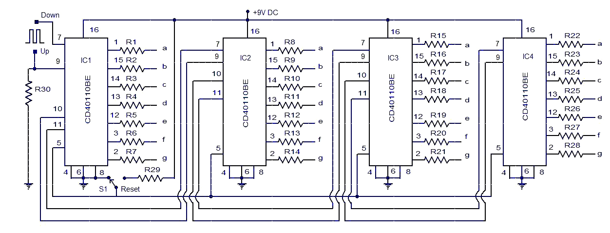
                 Circuit diagram of the electronic letterbox with letter-counting facility


                                                 Pulse Detecting Genetic Circuit 

                                                    Gambar terkait

In digital logic and computing, a counter is a device which stores (and sometimes displays) the number of times a particular event or process has occurred, often in relationship to a clock signal. The most common type is a sequential digital logic circuit with an input line called the clock and multiple output lines. The values on the output lines represent a number in the binary or BCD number system. Each pulse applied to the clock input increments or decrements the number in the counter.
A counter circuit is usually constructed of a number of flip-flops connected in cascade. Counters are a very widely used component in digital circuits, and are manufactured as separate integrated circuits and also incorporated as parts of larger integrated circuits.


In electronics, counters can be implemented quite easily using register-type circuits such as the flip-flop electronics is a complete language of communication and a wide variety of classified into:
  • Asynchronous (ripple) counter – changing state bits are used as clocks to subsequent state flip-flops
  • Synchronous counter – all state bits change under control of a single clock
  • Decade counter – counts through ten states per stage
  • Up/down counter – counts both up and down, under command of a control input
  • Ring counter – formed by a shift register with feedback connection in a ring
  • Johnson counter – a twisted ring counter
  • Cascaded counter
  • Modulus counter.
Each is useful for different applications. Usually, counter circuits are digital in nature, and count in natural binary. Many types of counter circuits are available as digital building blocks, for example a number of chips in the 4500 series implement different counters.
Occasionally there are advantages to using a counting sequence other than the natural binary sequence—such as the binary coded decimal counter, a linear-feedback shift register counter, or a Gray-code counter.
Counters are useful for digital clocks and timers, and in oven timers, VCR clocks, etc.

A robust cellular counter could enable synthetic biologists to design complex circuits with diverse behaviors. The existing synthetic-biological counters, responsive to the beginning of the pulse, are sensitive to the pulse duration. Here to present a pulse detecting circuit that responds only at the falling edge of a pulse–analogous to negative edge triggered electric circuits. As biological events do not follow precise timing, use of such a pulse detector would enable the design of robust asynchronous counters which can count the completion of events. This transcription-based pulse detecting circuit depends on the interaction of two co-expressed lamb doid phage-derived proteins: the first is unstable and inhibits the regulatory activity of the second, stable protein. At the end of the pulse the unstable inhibitor protein disappears from the cell and the second protein triggers the recording of the event completion. Using stochastic simulation we showed that the proposed design can detect the completion of the pulse irrespective to the pulse duration. In our simulation we also showed that fusing the pulse detector with a phage lambda memory element we can construct a counter which can be extended to count larger numbers. The design principle is a new control mechanism for synthetic biology which can be integrated in different circuits for identifying the completion of an event.


Synthetic biology borrows the basic principles from engineering and molecular biology, and applies these principles in designing, testing, validating and assembling genetic parts into larger systems . Over the past 15 years synthetic biology researchers have designed numerous synthetic genetic circuits and a trend of increasing circuit complexity seems likely . The design principles of electrical circuits have inspired and have been incorporated in the construction of many synthetic genetic circuits . Like in electrical circuits, memory is an essential functional unit in biological systems which records the received stimulus and directs the cell fate in alternate directions based on the logged experience. Consequently, a diverse design approach has been exercised in registering a biological event in a cell and probing the record at a later time .


A counter is another basic device that track events and is extensively used in building a wide range of complex electrical circuits. The existence of counting mechanism in wild organisms has been documented .  With the help of a robust cellular counter, synthetic biologists could design novel control mechanisms and applications based on the occurrence of events. A few successful circuits have been constructed .
 
The design of a counter makes the use of memory and a single memory unit can work as a counter capable of counting a single event. Such a one-counter can be cascaded to count numbers larger than one but counting high numbers will be challenging because the number of orthogonal systems will increase linearly with the maximum number we want to count. One way to overcome this difficulty is to use set-reset memory devices ( Integral list point )


Another potential challenge in designing a robust biological counter is the ability to count at completion of the event. The existing designs of the counters are sensitive to the pulse duration–a brief pulse will be ignored and a lengthy pulse can cause the counter to count ahead .
This problem can be evaded if we can design a counter that advances the count at the end of the pulse, as is the common practice in electrical counter design . The essential component in such a design is a pulse detecting circuit that responses only at the falling edge of the pulse stimulus. Use of such a pulse detector will make the counter robust to pulse duration.  The design of the robust genetic pulse detector using the lambda CI repressor protein . By preventing the dimerization of CI protein until the triggering pulse completes, we identify the end of the event and subsequently the dimerized CI protein will trigger the reporter circuit. In simulation we tested and characterized the pulse detecting device to identify the limit of its operation. We designed an extendable one-counter by coupling this pulse detecting circuit with a lambda switch based memory .
Using a detailed chemical modeling and stochastic simulation we show that the presented robust pulse detector works with practical biologically parameters and can be used in designing falling edge triggered genetic counter. 


                                            A new design control for pulse detection


In principle, it is possible to design an asynchronous counter using both negative edge triggering (NET) and positive edge triggering (PET). However, in electronics most of the asynchronous counters are designed using NET because it makes the linking to flip-flops easier which should change state when the previous bit changes from high to low. An additional advantage of designing counters with NET is that they count events irrespective of the event’s duration and frequency. 

is analogous to synchronous counters found in digital systems, and counted correctly only in response to pulses of defined duration. In contrast, the design of the counter outlined in corresponds to asynchronous counters. A pulse detector circuit that triggers only at the falling edge of a pulse would facilitate the design of an asynchronous counter and can be used in designing many other genetic circuits. We have a pulse detector circuit that uses distinctive characteristics of the lambda CI repressor protein to explore design considerations for a transcription-based biological negative edge detector. The bacteriophage lambda has a complex set of interlocking regulatory mechanisms that it uses to maintain the lysogenic state and to transition to the lytic state .
In the lysogenic state the lambda genome is integrated in the chromosome of host cell and replicated with cell division. In response to a DNA-damage signal, the lambda-phage exits the stable lysogenic state and enters the lytic state in which the phage lyses the cell, producing many new phage particles. 

One regulatory module in lambda genome, colloquially known as lambda switch, mediates this decision and consists of: cI and cro genes, two promoters (PRM and PR transcribing cI and cro respectively) and three operators (OR1, OR2, and OR3) in the OR region .
the three operators in the OR region enhance the cooperativity of the system with respect to cI and allow a hair-trigger response in switching from the CI-rich state to the Cro-rich state . 


Both CI and Cro proteins bind to the three operators with different affinities and control the transcription of cI and cro genes. RNA polymerase can transcribe gene cro when both OR1 and OR2 are free; similarly gene cI is transcribed when OR3 is free. CI protein can enhance the transcription from PRM promoter when bound to OR2. A moderate level of CI protein is maintained by shutting down the PRM promoter when CI level crosses a certain threshold. The double negative feedback mechanism along with the positive feedback from CI controls the expression of only one of the two genes (cI and cro) repressing the other and thereby allows the lambda phage maintaining its lysogenic state and switching to the lytic state . These features allowed Kotula et al.  to construct a memory element based on switching from the CI state to the Cro state. These authors also noted that the Cro state was quite stable, at least under the conditions tested. Thus, switching from the Cro to the CI state could also be used to record events; this is the approach used here.
One characteristic of CI and Cro proteins, important for our design, is that they bind to the OR operator sites in their dimer and higher-order multimers only; monomers have no activity. Therefore activation and repression of these PR and PRM promoters could be controlled by preventing the dimer formation of CI and Cro proteins. This is a key element of the genetic device we present here. In their study on operator and non-operator DNA binding of lambda repressor protein CI, Nelson and Sauer isolated a mutant of CI repressor bearing a mutation in the DNA binding surface, Asn55Lys (N55K) that eliminated the binding affinity of the CI-mutant to operator sites but increased the affinity to non-specific DNA binding sites . We recently demonstrated that CI (N55K) acts as a dominant negative inhibitor of the CI protein itself , presumably by forming mixed dimers as has been observed for the tet and lac repressors . This mutation should not affect the dimerization characteristics of the protein. We refer to this protein as dominant-negative CI (CIDN) which is used for blocking dimer formation of CI proteins. Inhibition of the activity of a transcription factor by complexation with a dominant negative partner has previously been found useful . Another protein that can be used to block the activity of lambda CI protein is the Antirepressor of P22, which appears to inactivate numerous lambdoid phage repressors .

The architecture of the pulse detecting circuit, assumed to be hosted in E coli bacterium, is shown in Fig 1(A). We placed both the wild-type cI and cIDN under the control of a single inducible promoter. A degradation tag is added with cIDN to ensure quick degradation of the monomeric proteins. One obvious candidate for the inducible promoter could be the TetA promoter PTetA . A much stronger RBS (RBS1) is required for cIDN than the RBS (RBS2) for cI. Experimentally one would use a reporter such as the lacZ gene under the control of PRM promoter. Essentially, the system works as follows: when the PTetA is induced (during the pulse), CIDN and CI transcripts are produced. Because of the stronger RBS associated with CIDN, many more CIDN molecules are present in the cell compared to CI molecules. Therefore, almost all of the CI monomers will form heterodimers with CIDN, and there will be no CI2 to activate PRM promoter. After the induction period, because of the degradation tag CIDN molecules degrade quickly giving CI molecules a chance to form dimers and activate PRM promoter. Fig 1(B) explains the input output relationship for the pulse detecting circuit.


An external file that holds a picture, illustration, etc.
Object name is pone.0167162.g001.jpg


Schematic representation of the negative edge triggered pulse detecting circuit.
(a) Components of the pulse detecting circuit. The central element is an artificial operon in which a regulated promoter directs transcription of high levels of an unstable inhibitor protein and lower levels of a target transcriptional regulator. In the specific version shown here, the tetracycline-regulated TetA promoter directs transcription of, firstly, a dominant-negative mutant of the lambda cI gene with a degradation tag (green), and secondly an intact version of the cI gene (red). TetR, the tetracyline repressor (gray), blocks transcription of this unit and PRM (which is activated by intact CI protein) transcribing lacZ (sky-blue) serves as an illustrative readout of circuit activity. (b) Behavioral characteristics of the circuit in response to an inducing pulse, with time proceeding downward. In the initial absence of the inducer tetracycline, neither of the proteins is made and lacZ is OFF. Upon addition of tetracycline, both proteins are made and the CIDN protein inhibits the wild-type protein, so lacZ remains OFF. Upon removal of the inducer, the CIDN protein is rapidly degraded while the wild-type CI protein remains intact, and activates lacZ transcription.


stochastic simulation, we analyzed the pulse detecting circuit to determine the range of parameters (e.g. relative strength of the RBS sites, degradation tag efficiency) of the model for which the circuit produced the desired behavior. After successful model validation, we combined the pulse counter with a lambda phage memory element to construct a one-counter circuit. The simulation results show, when parameters such as RBS strengths are in the right range, that the designed circuit is able to count the event completion and can be expanded to count larger numbers.


Relative strength of RBS sites

In order to prevent CI proteins from activating the PRM promoter, we need to block the homo-dimerization of wild type CI proteins. In our design, we plan to produce enough CIDN proteins so that all CI wild-type proteins will form heterodimers with CIDN rather homo-dimers. Since both the wild type and dominant type cI genes are transcribed from the same promoter PTetA the best way to achieve that is to use RBS sites with different strength with cI and cIDN genes. In our theoretical calculation it was found that the RBS of cIDN (RBS1) should be at least 10 times stronger than the RBS of cI (RBS2). In order to verify that we tested our model with a range of RBS1:RBS2 strength ratios. It was found that if the strength ratio between RBS1 and RBS2 is 20:1 or greater, it is possible to prevent the dimer formation of CI proteins completely and thereby the reporter gene lacZ becomes activated only when the pulse is finished. Fig 2 shows the simulation of the pulse detector circuit with RBS1:RBS2 = 20:1. As the figure shows, the abundance of CIDN molecules ensures that no CI2 dimer is formed to activate PRM promoter. After the pulse, the degradation tag attached to cIDN quickly removes CIDN protein molecules from the cell allowing CI to form homo-dimers and trigger the reporter circuit. In our simulations, we varied the RBS1:RBS2 ratio from 2 to 25, and it was found that if it is less than 20 then the pulse detection might not work very precisely. As an example the results for the RBS1:RBS2 = 10 is included in S1 Fig. As we can see if RBS1:RBS2 is less than 20 then we have some CI2 in the system before the pulse is finished thus the reporter circuit might start to respond earlier. The effect is more visible for lengthier pulse durations as will be discussed later. In order to compare the effect of RBS strength ratios directly we put all the LacZ responses and the corresponding CI2 concentration changes in S2 Fig. From those response curves it is clear that if the RBS1:RBS2 ratio is less than 20 then CI2 concentration start to rise before the pulse finishes and reporter circuit starts to respond accordingly. 

                        An external file that holds a picture, illustration, etc.
Object name is pone.0167162.g002.jpg   


Response of the pulse detector circuit in Fig 1 for a pulse duration of ½ bacterial cell-cycle (CC) [1020 sec].
The pulse was activated at 10.2 CC (20808 sec) and deactivated at 10.7 CC (21828 sec). The relative strength of RBS1 and RBS2 was 20:1 and the degradation tag had half-life of 4 minutes. The response is average of 20 simulation runs.


Influence of degradation tag associated with cIDN

The second most important challenge in the design is to quickly remove CIDN from the cell after the completion of the pulse, so that we have enough CI concentration present in the cell to induce the reporter circuit. Evidently, adding a degradation tag to cIDN is a workable solution. However, it should be noted that attaching a degradation-tag will also affect the concentration of CIDN during the pulse. So we need a well-chosen degradation-tag so that we have sufficient CIDN concentration to prevent formation of CI2 during the pulse and after the pulse the CIDN molecules are quickly removed from the system. We therefore, experimented with various degradation-tags of different strengths. We run simulations with degradation-tags with half-life 2, 4, 8 and 16 minutes. The effect of the strength of degradation-tag is shown in Fig 3. From Fig 3, it is found that if degradation-tag is too strong (e.g. half-life 2 mins) then CI molecules start to form dimers before the pulse is finished and if the tag is too weak (e.g. half-life 16 mins) then CIDN remains in the cell for long after the pulse and does not allow formation of CI-dimers to activate the reporter circuit. The degradation-tag with half-life of 4 minutes matches well with the RBS1:RBS2 = 20 to maintain CIDN concentration high enough to prevent formation of CI2 during the pulse and quickly eradicate CIDN from the cell to activate the reporter circuit after the pulse. S3 Fig shows that the combination of deg-tag of 4 minutes and RBS1:RBS2 ratio of 20 or higher is effective in building a working model for the pulse detecting circuit.


An external file that holds a picture, illustration, etc.
Object name is pone.0167162.g003.jpg


Response of the pulse detector circuit in Fig 1 with degradation tags of different half-lifes (2, 4, 8 and 16 minutes).
For brevity only responses of LacZ and CI molecules were displayed for each deg-tag using the same color. The pulse was activated at 10.2 CC (20808 sec) and deactivated at 10.7 CC (21828 sec). The relative strength of RBS1 and RBS2 was 20:1. The response is average of 20 simulation runs. 


Effect of pulse length

Another important characteristic of the proposed pulse detector is its insensitivity to pulse duration. Since the circuit responses at the falling edge of the pulse it is not affected by the length of the pulse. In order to confirm that ability of the designed circuit we simulated the circuit with different pulse duration, specifically with pulses of 1.0 CC (cell-cycle) and 1.5 CC. Fig 4 shows the response of the designed pulse detector circuit with a RBS1:RBS2 ratio of 20 and 4 minutes degradation tag. Although the duration of the pulse was made double (Fig 4(A)) and triple (Fig 4(B)) there was no significant presence of CI2 in the cell to activate the lacZ reporter throughout the pulse. Consequently the lacZ responded only after the pulse was finished making the circuit independent of the pulse duration. We also extensively studied the effect of other ratios of RBS1:RBS2 and strength of degradation tag for these two pulse lengths and the summary of those results are presented in S4 and S5 Figs. The observation was analogous to what we found in case of the pulse duration of ½ cell-cycle–if the circuit is designed with a RBS1:RBS2 ratio of 20 or more and a degradation tag with 4 minutes half-life then it will behave as a perfect pulse detector circuit irrespective to pulse duration. 

An external file that holds a picture, illustration, etc.
Object name is pone.0167162.g004.jpg


Response of the pulse detector circuit in Fig 1 for different pulse durations.
The RBS1:RBS2 ratio was set to 20 and a deg-tag of 4 minutes was used. Each response in the graph is the average of 20 simulations. (a) The pulse was activated at 10.2 CC (20808 sec) and deactivated at 11.2 CC (22848 sec) [duration 1 bacterial cell-cycle (CC)]. (b) The pulse was activated at 10.2 CC (20808 sec) and deactivated at 11.7 CC (23868 sec) [duration 1 ½ bacterial cell-cycle (CC)]. 

Design of a counter circuit with the embedded pulse detector

After we confirmed the reliability of the pulse detector circuit we fused a lambda memory circuit with it to design a synthetic counter. The bistable characteristic of lambda switch makes it a dependable memory device for recording the count after the pulse has been completed. The overall design of the counter circuit is shown in Fig 5. Initially the lambda memory is in Cro-rich state and retains that state until it is switched to CI-rich state in response to the completion of the pulse. With the beginning of the pulse which is simulated by the induction of the PTetA promoter, mRNAs of both cIDN and cI are transcribed. By the virtue of the stronger RBS1 enough CIDN proteins are translated from cIDN mRNA and those proteins form CIDN-CI dimers with CI monomers and prevent CI to form CI2 and activate the PRM promoter. Now when the pulse finishes, the transcription of cIDN and cI stops and the attached degradation-tag causes CIDN to be removed quickly from the cell allowing CI molecules to form dimers. The CI-dimers interact with the PRM promoter and switch the memory into CI-rich state from Cro-rich state. Once the memory has changed over to CI-rich state the feedback loops of lambda switch retains the memory in that state and thus records the completion of the pulse.
An external file that holds a picture, illustration, etc.
Object name is pone.0167162.g005.jpg
The design of the counter circuit.
The two components of the design are the falling edge pulse detector circuit shown in Fig 1 and the lambda memory switch.


However, for switching from Cro-rich state to CI-rich state we need sufficient amount of CI2 dimers present in the cell. According to some simulations we need approximately 70 ~ 100 nM CI for switching from Cro-rich state to CI-rich state. As shown in earlier sections, the strength ratio between RBS1 and RBS2 needed to be 20 or more to design a working pulse detector circuit. Taking that into consideration we experimented with different strengths of RBS1 and RBS2 so that we have a ratio of 25. We run our simulations under four conditions with [RBS1, RBS2] = [25x, 1x], [50x, 2x], [100x, 4x] and [200x, 8x] where 25x means that the RBS is 25 times stronger than the RBS of wild type cI. In every case, we used the degradation-tag with half-life of 4 minutes. Each simulation was run for 20 times and the summary of the results are shown in Fig 6. According to this simulation, if we have a 8 times stronger RBS attached to cI and a RBS 25 times stronger than that attached to cIDN then we will be able to design a reliable counter circuit with the pulse detector circuit and the lambda memory circuit. Fig 7 shows the average simulation of the circuit with the following setting. Under this setting, in 20 out of 20 runs, the circuit successfully switched from Cro-rich state to CI-rich state. This also advocates the robustness of the counter circuit.
An external file that holds a picture, illustration, etc.
Object name is pone.0167162.g006.jpg
Success rate of switching the memory device ON.
Each simulation was run 20 times with different [RBS1, RBS2] ratios: [25x,1x], [50x,2x], [100x,4x] and [200x,8x] where 25x means the RBS is 25 times stronger than the RBS in wild type cI.
An external file that holds a picture, illustration, etc.
Object name is pone.0167162.g007.jpg
Average simulation of the 1 bit pulse counter circuit.
The circuit was simulated for 30 bacterial CC (30X34 minutes). The duration of the pulse was 1.5 CC (1.5X34 minutes) and was activated at 10.2 CC (10.2X34 minutes).


In simulation we have shown that it is possible to construct a counter circuit using the designed pulse detector circuit along with the lambda memory switch. However, the usage of lambda switch imposes additional requirements as the Cro-rich state of lambda is very stable and switching it to CI-rich state needs significant amount of CI present in the system. Therefore, we need to use very strong RBS both for cI and cIDN genes so that we can get enough proteins per transcript. Alternatively, we can use a promoter with higher isomerization rate instead of PTetA. We can also consider stabilizing the cI and cIDN mRNAs as well. It is also possible to change the OR regions in lambda switch that makes switching from Cro-rich to CI-rich state easier. Hence, the counter circuit can be constructed by using one of these strategies or applying their combinations altogether.
Furthermore, in order to show the robust behavior of the counter circuit in response to the pulse duration, we experimented with various pulse durations–in particular we varied the pulse from 1 CC, 2.5 CC, 5 CC and 10 CC where 1 CC means 1 bacterial cell cycle of 34 minutes. We repeated each simulation 20 times for each setup. The counter circuit exhibited very robust behavior by successfully counting each pulse irrespective to the pulse duration in each experimental run. The average simulation of this 1 bit pulse counter circuit for various pulse durations is shown in the S6 Fig. However, when the pulse duration was set 0.5 CC then in 7 runs out of 20 the circuit failed to switch to CI-rich state or switched back to Cro-rich state. These results indicates that if the pulse duration is very short then the current circuit cannot response, nevertheless, it is possible to design a counter circuit, based on the same principle, that can count shorter pulses by changing system parameters. The simulations in this section indicate that the designed counter circuit is capable of counting a pulse of any duration greater than a minimum limit.
The designed counter circuit with the aid of pulse detector circuit can be cascaded for building counters that can count larger numbers. Fig 8 shows a two-counting circuit that makes use of FLP-FRT recombination. The flippase1 is transcribed from the PRM promoter along with YFP and cI once the circuit has switched to CI-rich state (i.e. after it has counted one). The Flippase1 then can remove the terminator allowing the PTetA promoter to transcribe CI and anti-CI proteins from 434. Subsequently the anti434CI and 434CI proteins can behave similar to CI and CIDN and switch 434Cro state to 434CI state interacting with respective promoters. Another FLP-FRT pair (flipppase2) can be added for subsequent counting as shown in Fig 8. Moreover, the capability of the pulse detector circuit to respond to the falling edge of a pulse would enable us designing the asynchronous counter and many other useful synthetic circuits.
An external file that holds a picture, illustration, etc.
Object name is pone.0167162.g008.jpg
Design of two or higher bit counters using the pulse detector circuit.


Conclusion

This work presents a synthetic circuit for detecting the falling edge of a pulse based on the interaction between two proteins. The basic principle of this design is to co-express two proteins from an inducible promoter and one of the proteins will interfere with the activity of the other and prevent the second protein from its usual activity. The first protein will also have a degradation tag attached so that it will be quickly removed from the cell when the induction subdues and thus will allow the second protein to return to its natural action. In our design we used the lambda CI protein and one of its mutants which we call CIDN for designing the pulse detector circuit. The interaction between CI and CIDN has been characterized in laboratory experiments and it was found that the repression of CI by CIDN occurs in a dose dependent manner . Using stochastic simulation we showed that by selecting the RBS sites associated with cI and cIDN and the degradation-tag attached to cIDN we can construct a pulse detecting circuit that is robust to pulse duration. Since the biological events are not precisely timed, a pulse detecting circuit that can work irrespective to pulse duration would be very attractive to synthetic biologists. Fusing the pulse detector with lambda memory circuit we constructed a counter that can count the completion of an event. In our simulation the counter exhibited robust behavior. The design is generalized enough to be extended for constructing counter capable of counting higher numbers. Furthermore, the pulse detecting circuit can also be used for designing asynchronous biological counters.
The presented design is a new control mechanism for synthetic biology. The design principle can be used for many other circuits for detecting the completion of an event. Most of the verification of the design has been done in simulation but model based design has been used in previously designed synthetic circuits (e.g. toggle switch, repressilator). However, the results generated by the model could be successfully reproduced in experiments only after tuning the circuit. Although stochastic models represents the biological systems more closely compared to the deterministic models (e.g. differential equation based model), it is expected that some tuning of the model would be necessary to implement it in experiments . Therefore, the designed pulse detecting circuit can be constructed in vivo perhaps with some necessary adjustments and can play as a valuable component for synthetic biology.


Methods

We used a reaction based model for simulating different components of our circuits. Each model consists of a set of chemical reaction and we used Gillespie algorithm  for stochastic simulation of each model. The basic components of different models are: homo-dimerization of CI and Cro proteins and hetero-dimerization of CI-CIDN proteins, binding of CI2 and Cro2 dimers to OR operator sites (OR1, OR2 and OR3), binding of RNA polymerase to PRM, PR and PTetA promoters, isomerization of different promoters, transcription of cI and cIDN, cro and lacZ from respective promoters and translation of those transcripts corresponding to associated RBS sites, degradation of mRNA molecules and protein monomers and dimers according to their half-life or attached degradation-tag’s half-life respectively.
All the model parameters are set using biochemical data. Most of the parameters came from the model of lambda switch by Morelli.


                 X O  110 110 110  110   Astrophysical and Geophysical Fluid Dynamics


Exploring the operation of hydrodynamic and magnetohydrodynamics processes in a variety of contexts, including the ocean and atmosphere, planets, stars, accretion discs, the interstellar medium, and galaxy clusters, as well as in more idealised, generic, contexts.

Planets, stars and galaxies contain electrically conducting fluids or plasmas. Motions in these fluids induce magnetic fields, which can significantly affect the structure, activity, evolution and other basic properties of the bodies concerned.

Although the fundamental equations governing these processes are thought to be known, the phenomena that arise in different objects and regimes vary greatly, and the detailed mechanisms involved are still the subject of vigorous research.


The object load is interest include:
  • planetary dynamos
  • geomagnetic field reversals
  • magnetic torques in accretion discs binary stars
  • galactic dynamos
  • interstellar turbulence
  • magnetic Taylor–Couette flow

                                          Particle Astrophysics

One of the goals of Particle Astrophysics is to use the early universe to test the consistency of new developments in particle physics and quantum gravity.
An example is the five dimensional brane-world theory that has arisen from superstring models. We are also investigating the effects of quantum gravity on particle physics experiments.

We learn to satellite observations of the universe today. This enables us to explain the pictures of the universe taken by microwave satellites, and also provides a set of initial conditions for galaxy formation, linking in with research areas in astrophysical fluid dynamics.


_________________________________________________________________________________
    
      
                                     Hasil gambar untuk usa flag stem cells 
                                                                   Pro - Life

         Gambar terkait     Gambar terkait


                   e- Locker Detector in Point Virtual Matrix and Human Stem Cells

__________________________________________________________________________________

Senin, 29 Juli 2019

e- lockers and detectors for application the space and time AMNIMARJESLOW GOVERNMENT 91220017 XI Xie Lock and Time space 0209010014 LJBUSAW __ Thanks for Lord Jesus Give and Give for Our Thanksgiving ___ Gen. Mac Tech e- A/D/S Tour in Locker time and space detecting S H I N to A / D / S up going G-Lock Astronomy Celluloid


                                                   Gambar terkait

                       Electronic Re-Charging Station.jpg


In the world of electronics and mechanics as well as informatics a locking device is needed so that a system works so that the system can be controlled properly, especially the control using detector techniques that exist both in terms of the A / D / S Tour in Space Time.


                                                                       Love in  S H I N to A/D/S Tour  


                                                                   Hasil gambar untuk electronic detector circuit


                                                         ( Gen . Mac Tech Zone e- Locking and Detection ) 


                             Hasil gambar untuk g-lock in astronomy
   
                               Gambar terkait

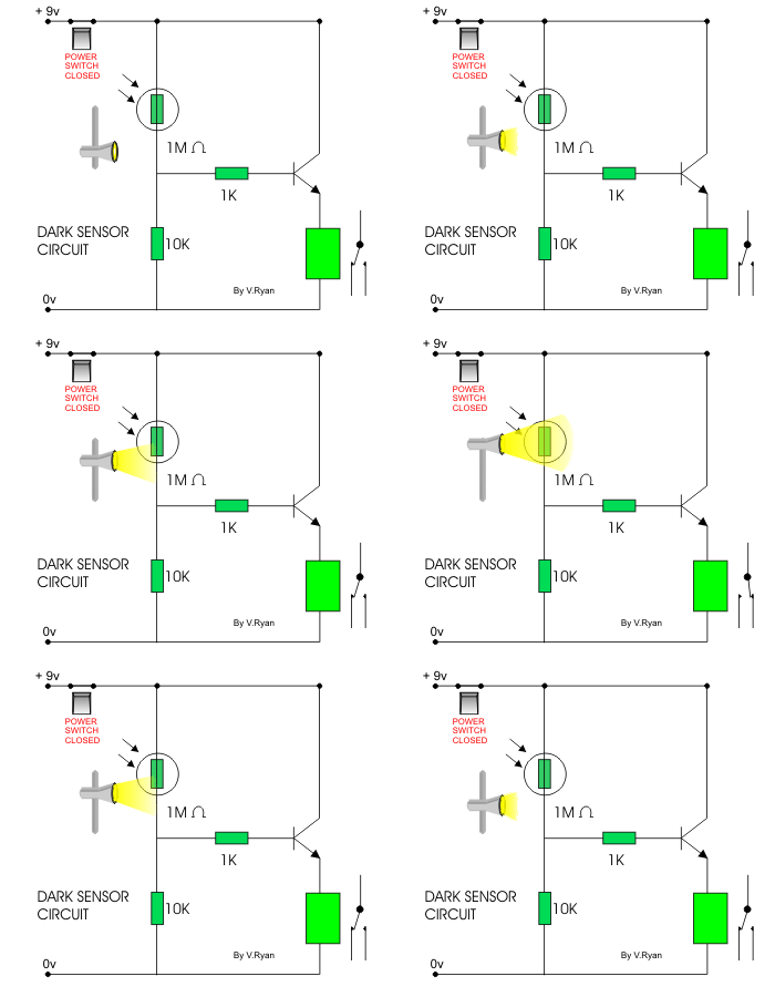
                                                         Dark Detector


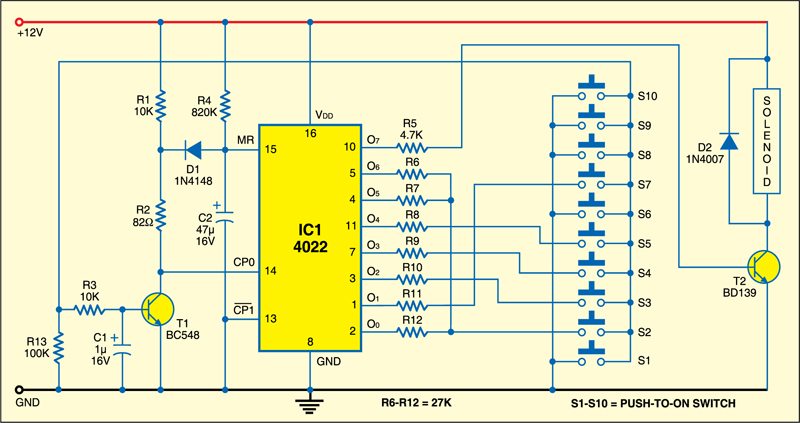
                                      II0  Code Lock Circuit using Transistor 

 
one-transistor-code-lock-circuit


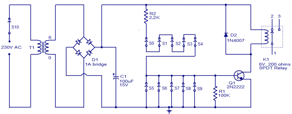
electronic circuit is one of the simplest code lock circuit one can make easily in their home.This circuit uses one transistor a relay and a few passive components in it.The logic of this circuit is also very simple.Even this circuit is simple it works really fine and efficient for a simple cupboard or shelf lockers.


WORKING OF CODE LOCK CIRCUIT:

The working of this circuit is very simple it just uses a transistor as a switch with a relay at its collector as load.Five switches (S0 to S4) is arranged in series with a current limiting resistor R2 is connected across it.Another five switches (S5 to S9) is connected across the base of the transistor and the ground.So this circuit uses transistor as a switch and the transistor will ON only when all the switches from S0 to S4 was in ON state and S5 to S9 was in OFF state.This was the primary logic for this circuit.Lets see how to design it as per our wish.
Now coming to the design of this circuit we should shuffle arrange the switches in the panel in such a way so that the password will be too  tough to guess.For example if your password is 58901 you should arrange it in the circuit that the keypad 5 will be your switch S0 then 8 as S1,9 as S2,0 as S3 and 1 as S4.Since it was in series the voltage will not pass through unless you pressed the keys in right combination. 


Thus if correct combination of the key was pressed the transistor will be switched ON and it activates the relay circuit thus it opens the lock.If even on key from S5 to S9 was pressed then there will be no voltage to transistor thus making it to remain in OFF state.The device used to controlled using lock circuit can be connected through the relay terminals.The transformer T1,bridge D1 and capacitor C2 forms the power supply of the circuit.And diode D2 is a freewheeling diode which was used with relay circuit.

UPDATE:

The above Circuit diagram have a small bug, the resistor R1 should not be pulled down to ground. It should be connected in such a way to connect the switch S9 and base of the transistor Q1 in order to bias it for switching the relay ON.


                         Gambar terkait 


                Electronic Component of Transducers, sensors, detectors

  1. Transducers generate physical effects when driven by an electrical signal, or vice versa.
  2. Sensors (detectors) are transducers that react to environmental conditions by changing their electrical properties or generating an electrical signal.
  3. The transducers listed here are single electronic components (as opposed to complete assemblies), and are passive (see Semiconductors and Tubes for active ones). Only the most common ones are listed here.

                                                 Electronic Combination Lock


                     II0  II0  Importance and Classification of Electronic Security System 


Electronic security system refers to any electronic equipment that could perform security operations like surveillance, access control, alarming or an intrusion control to a facility or an area which uses a power from mains and also a power backup like battery etc. It also includes some of the operations such as electrical, mechanical gear. Determination of a type of security system is purely based on area to be protected and its threats.


Importance of Electronic Security System:

The electronic security systems are broadly utilized within corporate work places, commercial places, shopping centers and etc. These systems are also used in railway stations, public places and etc. The systems have profoundly welcomed, since it might be worked from a remote zone. And these systems are also utilized as access control systems, fire recognition and avoidance systems and attendance record systems. As we are know that the crime rates are increasing day by day so most of the people are usually not feeling comfort until they provide a sure for their security either it may be at office or home.  So we should choose a better electronic system for securing purpose.

Classification of security system can be done in different ways based on functioning and technology usage, conditions of necessity accordingly. Based on functioning categorizing electronic security system as follows:


  • CCTV Surveillance Security System
  • Fire Detection/Alarming System
  • Access Control/Attendance System 


CCTV Surveillance Systems:

It is the process of watching over a facility which is under suspicion or area to be secured; main part of the surveillance electronic security system consists of camera or CCTV cameras which forms as eyes to surveillance system. System consists of different kinds of equipment which helps in visualizing and saving of recorded surveillance data. The close-circuits IP cameras and CCTVS transfers image information to a remote access place. The main feature of this system is that, it can use any place where we watch the human being actions. Some of the CCTV surveillance systems are cameras, network equipments, IP cameras and monitors. In this system, we can detect the crime through the camera, the alarm rings after receiving the signal from the cameras which are connected CCTV system; to concern on the detection of interruption or suspicion occurrence on a protected area or capability, the complete operation is based on the CCTV surveillance system through internet. The figure below is representing the CCTV Surveillance Systems.


CCTV Surveillance System
                          CCTV Surveillance System


P Surveillance System:

The IP-Surveillance system is designed for security purpose, which gives clients capability to control and record video/audio using an IP PC system/network, for instance, a LAN or the internet. In a simple way, the IP-Surveillance system includes the utilization of a system Polaroid system switch, a computer for review, supervising and saving video/audio, which shown in figure below.
In an IP-Surveillance system, a digitized video/audio streams might be sent to any area even as far and wide as possible if wanted by means of a wired or remote IP system, empowering video controlling and recording from anyplace with system/network access.


IP Surveillance Network
                                IP Surveillance Network

Attendance and Access Control Systems:

System which provides a secured access to a facility or another system to enter or control it can be called as an access control system. It can also act as attendance providing system which can play a dual role. According to user credentials and possessions access control system is classified, what a user uses for access makes system different, user can provide different types like pin credentials, biometrics or smart card. System can even use all possessions from user for a multiple access controls involved.  Some of the attendance and access control systems are:
  • Access Control System
Access Control System
  • RF based access control and attendance system:


Finger Print Attendance-Access Control System
RF based Card access control and attendance system
         RF based Card access control and attendance system

Electronic security system extends its applications in various fields like home automation, Residential (homes and apartments), commercial (offices, banks lockers), industrial, medical, and transportations. Some of the applications using electronic security system are electronic security system for railway compartment, electronic eye with security, electronic voting system are the most commonly used electronic security system.

One of the examples related to electronic security system:

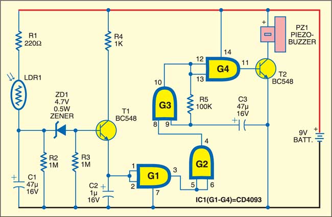
 From the block diagram, the system is mainly designed based on Electronic eye (LDR sensor); we use this kind of systems in bank lockers, jewelry shops. When the cash box is closed, the neither buzzer nor the binary counter/divider indicates that box is closed. If anyone tries to open the locker door then automatically a light falls on the LDR sensor then the resistance decreases slowly this cause buzzer to alert the customer. This process continues until the box is closed.
Electronic Eye Controlled Security System                                  Electronic Eye Controlled Security System


                         Hasil gambar untuk electronic lockers circuit 

                                          Locker Guard Project


                  Intelligent Electronic Lock Circuit 

securing anything is through mechanical locks, which operate with a specific key or a few keys; but, for locking a large area many locks are necessary. However, conventional locks are heavy and do not offer the desired protection as they can be easily broken down by using some tools. Therefore, security breaching problems are associated with the mechanical locks.However to decide the electronic security system problems that are associated with the mechanical locks.

                           Intelligent Electronic Lock  


Nowadays, many devices’ operations are based on digital technology. For example, digital based door lock systems for auto door opening and closing, token-based-digital-identity devices are all based on digital technology. These locking systems are controlled by a keypad and are installed at the side hedge of the door.  intelligent electronic security lock system offers freedom from physical and mental stress faced by a person while moving away from their home.

1. Intelligent Electronic Lock Circuit Diagram:

The below shown circuit represents an intelligent electronic lock , which is built using transistors only. To open this electronic lock, one has to press switches S1 through S4 serially. For dishonesty, you may explain these switches with different numbers on the keypad. For example, if you want to use 10 switches 0 to 9 on the keypad, use any four arbitrary numbers out of these switches and remaining 6 numbers may be explained on the leftover switches. These switches may be wired in parallel to disable S6 switch. When four password digits are mixed with remaining 6 digits, which are connected across disable switch terminals, energization of the RL1 relay by unknown person is prohibited.

                                          Circuit Diagram of Intelligent Electronic Lock

For authorized persons or known persons, a four-digit password is very easy to remember. To strengthen the relay RL1, one has to press the switches S1 to S4 in sequence within six seconds. Each of the switches will take 0.75 to 1.25 seconds time duration. The relay will not work if time duration is less than 0.75 Sec or above 1.25Sec. A special characteristic of this electronic lock circuit is the pressing of any switch wired across the switch S6 which will guide to disable of the whole circuit for about one minute. This circuit comprises sequential switching, relay latch up sections and disabling. The disabling section consists of Transistors T1, T2 and Zener diode ZD5. The function of the disabling section is such that- when the disable switch S6 is pressed, it cuts off the positive supply to the sequential switching and the relay latches up sections for one minute.
During idle state, the C1 capacitor is discharged and the voltage is less than 4.7V. Thus, T1 transistor and Zener diode are in non-conduction state. So the collector voltage of the T1 transistor is higher than transistor T2. Therefore, +12V is extended to the relay latch up and sequential switching sections. The sequential switching includes Transistors: T3, T4, T5; Zener diodes ZD1, ZD2, ZD3; Tactile switches S1 to S4; and, Timing capacitors: C2 to C4. In this electronic switch, when the tactile switches are activated, then the timing capacitors are charged through resistors. Thus, while activating tactile switches sequentially, transistors T3, T4 and T5 remain in conduction for a few seconds (T3 for 6 seconds, T4 for 3 seconds, and T5 for 1.5 seconds). 

To activate the tactile switches, the time taken is greater than 6 seconds, and the T3 transistor stops performing due to the time lapse. Thus, Sequential switching is not achieved and it is not possible to energize the relay RL1. However, on correct operation of sequential switches S1, S2, S3 and S4, the capacitor C5 is charged through R9 resistor, and the voltage across it increases above 4.7 volts. Next the  transistors T6, T7, T8 as well as the Zener diode start conducting and the RL1 relay gets energized. Next, if you turn on the reset switch S5 for a moment, the C5 capacitor is instantly discharged through the R8 resistor, and the voltage across it falls below 4.7 volts. Therefore the transistors T6, T7, T8 and the Zener diode ZD4 stop conducting again and the RL1 relay de-energizes.

2. Password Based Door Locking System:

In this password based door locking system , a keypad is arranged to open and close the door. After entering a password, if it matches with the stored one, then the door will unlock for a limited period of time. After extending the unlocking process for a fixed period of time, the relay energizes, and then the door gets locked again. If any unauthorized person enters a wrong password in an attempt to open the door, then this system immediately switches a buzzer

The working of this project can be described by the above block diagram. It consists of blocks as a microcontroller, a keypad, a buzzer, an LCD, a stepper motor and a motor driver.

Block Diagram of Password Based Door Locking System

The keypad is an input device which helps to enter a password to open the door. Then, it gives the entered code signals to the microcontroller. The LCD and buzzer are the indicating devices for alarming and displaying the information. The stepper motor moves the door to open and close and the motor driver drives the motor after receiving the code signals from the microcontroller.
The microcontroller which is used in this project is from 8051 families and that is programmed with the Keil software. When a person enters a password through a keypad, then the microcontroller reads the data and contrasts it with the stored data. If the entered password matches with the stored data, then the microcontroller sends the information to the LCD, which displays this information: the code is valid. Also, it sends the command signals to the motor driver to rotate the motor in a particular direction such that the door opens. After some time, the spring system with a particular time delay closes its relay, and then the door gets to its normal position,
If a person challenging to open the door enters a wrong password, then the microcontroller switches the buzzer for further action. In this way, a simple door-electronic-lock system can be implemented with the use of a microcontroller

3. ATmega Based Garage Door Opening:


ATmega Based Garage Door Opening by Edgefxkits.com

This is an advanced project compared to the above project. This project uses android technology instead of a keyboard for opening and closing the door. Hence, users can use their Android mobiles for opening and closing the door.
The main intention of this project is to unlock a garage door with an Android-OS-based device such as mobile or tablet by entering a single password through the Android application. This system uses a microcontroller, a Bluetooth modem, a buzzer, an Android mobile, a relay driver, lamps and relays for attaining the remote-controlled operations of the door.

ATmega Based Garage Door Opening by Edgefxkits.com

The Android based device is connected to this system through a Bluetooth device. The Bluetooth device is arranged to the microcontroller which  is programmed with a particular password for opening and closing the garage door.
Before sending this information to the microcontroller, the Bluetooth on the phone is attached to the control device which is paired to the Bluetooth modem. After entering the password in the android device, it sends the data to the microcontroller through a Bluetooth. Then it compares that data with the password stored in the microcontroller. If the two passwords match, then the microcontroller sends the control signals to the relay driver.
Then, the relay performs mechanical operations to open and close the garage door through the motor. Here, the motor is replaced with the lamp for visualization purpose. If the entered password is wrong, then the system generates an alarm.
Thus, this is all about intelligent electronic lock and basic procedure based on electronic door lock system.


   II0 II0 II0  Space-Time Ripples: How Scientists Could Detect of Lockers Gravity Waves


For years, scientists have been trying — and failing — to detect theoretical ripples in space-time called gravitational waves.
Four gravitational wave detectors are currently in operation. 

Gravitational waves, predicted by Einstein's theory of general relativity, are thought to be created by some of the most violent events in the universe, such as the collision of two neutron stars.
 Neutron stars are extremely dense dead stars left over after supernova explosions. When two merge into each other, they are predicted to release strong gravitational waves that should be detectable on Earth.

A new way of seeing the universe
Einstein's theory of general relativity describes how objects with mass bend and curve space-time. Imagine holding out a taut bedsheet and placing a football in the center. Just as the bed sheet curves around the football, space-time curves around objects with mass.
And like the ripples moving across a lake, the distortion in space-time caused by accelerating objects gradually decreases in strength, so by the time they finally reach Earth, they are very hard to detect. Hard, but not impossible. detecting gravitational waves opens up a new way of investigating the universe.
The waves could also help researchers probe some other mysterious and powerful cosmic events.
"Gravitational waves have great penetrating power, so they will allow us to see directly to the center of the systems responsible for supernova explosions, gamma-ray bursts and a wealth of other systems so far hidden from view. we need additional detector for looking for energy in 4 gravitation .


Gravity is most accurately described by the general theory of relativity (proposed by Albert Einstein in 1915) which describes gravity not as a force, but as a consequence of the curvature of spacetime caused by the uneven distribution of mass. 

Albert Einstein called gravity a distortion in the shape of space-time. ... Newton's theory says this can occur because of gravity, a force attracting those objects to one another or to a single, third object. Einstein also says this occurs due to gravity -- but in his theory, gravity is not a force.

According to Newton , gravity is a force expressed mutually between two objects by the virtue of their masses(heavier the objects, more the gravity)…he considered gravity a pull. According to Einstein , gravity was a curvature in the 4-dimensional space-time fabric proportional to objects masses.

“Imagination is more important than knowledge,” Einstein would say. It's no coincidence that around the same time, Einstein began to use thought experiments that would change the way he would think about his future experiments. ... His work on gravity was influenced by imagining riding a free-falling elevator. we have Illustration about 240 keypad as like as electronic lock switch in Input for e- S H I N to A / D / S tour and then to detecting gravitation energy to out space in space and time .
 

In space, it is possible to create "artificial gravity" by spinning your spacecraft or space station. ... Technically, rotation produces the same effect as gravity because it produces a force (called the centrifugal force) just like gravity produces a force.

              Gambar terkait
The gravitational pull of the moon pulls the seas towards it, causing the ocean tides. Gravity creates stars and planets by pulling together the material from which they are made. Gravity not only pulls on mass but also on light. Albert Einstein discovered this principle.

Does the influence of gravity extend out forever? ... As you get farther away from a gravitational body such as the sun or the earth (i.e. as your distance r increases), its gravitational effect on you weakens but never goes completely away; at least according to Newton's law of gravity

to summarize, general relativity says that matter bends spacetime, and the effect of that bending of spacetime is to create a generalized kind of force that acts on objects. However, it isn't a force as such that acts on the object, but rather just the object following its geodesic path through spacetime

The better news is that there is no science that says that gravity control is impossible. First, we do know that gravity and electromagnetism are linked phenomena. ... Historically, gravity has been studied in the general sense, but not very much from the point of view of seeking propulsion breakthroughs .


Earth's gravity is what keeps you on the ground and what makes things fall. ... So, the closer objects are to each other, the stronger their gravitational pull is. Earth's gravity comes from all its mass. All its mass makes a combined gravitational pull on all the mass in your body . 


Gravity from Earth keeps the Moon and human-made satellites in orbit. It is true that gravity decreases with distance, so it is possible to be far away from a planet or star and feel less gravity. But that doesn't account for the weightless feeling that astronauts experience in space .


It is a common misconception that astronauts in orbit are weightless because they have flown high enough to escape the Earth's gravity. In fact, at an altitude of 400 kilometres (250 mi), equivalent to a typical orbit of the ISS, gravity is still nearly 90% as strong as at the Earth's surface.

 Einstein said it is impossible, but as Jennifer Ouellette explains some scientists are still trying to break the cosmic speed limit – even if it means bending the laws of physics. "It is impossible to travel faster than light, and certainly not desirable, as one's hat keeps blowing off."


Also, under Einstein's theory of general relativity, gravity can bend time. Picture a four-dimensional fabric called space-time. When anything that has mass sits on that piece of fabric, it causes a dimple or a bending of space-time.

Albert Einstein, in his theory of special relativity, determined that the laws of physics are the same for all non-accelerating observers, and he showed that the speed of light within a vacuum is the same no matter the speed at which an observer travels.

The special theory of relativity implies that only particles with zero rest mass may travel at the speed of light. Tachyons, particles whose speed exceeds that of light, have been hypothesized, but their existence would violate causality, and the consensus of physicists is that they cannot exist.

The faster the relative velocity, the greater the time dilation between one another, with the rate of time reaching zero as one approaches the speed of light (299,792,458 m/s). This causes massless particles that travel at the speed of light to be unaffected by the passage of time.

 The force of gravity is the weakest at the equator because of the centrifugal force caused by the Earth's rotation and because points on the equator are furthest from the center of the Earth. The force of gravity varies with latitude and increases from about 9.780 m/s2 at the Equator to about 9.832 m/s2 at the poles.

 In string theory, believed to be a consistent theory of quantum gravity, the graviton is a massless state of a fundamental string. If it exists, the graviton is expected to be massless because the gravitational force is very long range and appears to propagate at the speed of light.

 The gravitational constant, called G in physics equations, is an empirical physical constant. It is used to show the force between two objects caused by gravity. The gravitational constant appears in Newton's universal law of gravitation. G is about 6.67408 ×10¹¹ N⋅m2/kg2, and is denoted by letter G

  
                 Gambar terkait

 Wormholes ( virtual point matrix )  are consistent with the general theory of relativity, but whether wormholes actually exist remains to be seen. A wormhole could connect extremely long distances such as a billion light years or more, short distances such as a few meters, different universes, or different points in time. 


According to the current understanding of physics, an object within space-time cannot exceed the speed of light, which means an attempt to travel to any other galaxy would be a journey of millions of earth years via conventional flight. 

Real world and Retro is possible , Because of the vastness of those distances, interstellar travel would require a high percentage of the speed of light; huge travel time, lasting from decades to millennia or longer. The speeds required for interstellar travel in a human lifetime far exceed what current methods of spacecraft propulsion can provide.

              Gambar terkait 


A causal loop is a paradox of time travel that occurs when a future event is the cause of a past event, which in turn is the cause of the future event. Both events then exist in spacetime, but their origin cannot be determined. 


However, making one body advance or delay more than a few milliseconds compared to another body is not feasible with current technology. As for backwards time travel, it is possible to find solutions in general relativity that allow for it, but the solutions require conditions that may not be physically possible


With an estimated light-travel distance of about 13.4 billion light-years (and a proper distance of approximately 32 billion light-years (9.8 billion parsecs) from Earth due to the Universe's expansion since the light we now observe left it about 13.4 billion years ago), astronomers announced it as the most distant ...

 Tachyons. In special relativity, it is impossible to accelerate an object to the speed of light, or for a massive object to move at the speed of light. However, it might be possible for an object to exist which always moves faster than light.


A spacecraft equipped with a warp drive may travel at speeds greater than that of light by many orders of magnitude. ... The problem of a material object exceeding light speed is that an infinite amount of kinetic energy would be required to travel at exactly the speed of light.

 In astronomy, the interstellar medium (ISM) is the matter and radiation that exists in the space between the star systems in a galaxy. This matter includes gas in ionic, atomic, and molecular form, as well as dust and cosmic rays. It fills interstellar space and blends smoothly into the surrounding intergalactic space


Explanations of why ships can travel faster than light in hyperspace vary; hyperspace may be smaller than real space and therefore a star ship's propulsion seems to be greatly multiplied, or else the speed of light in hyperspace is not a barrier as it is in real space. 

                               
                                    Hasil gambar untuk g-lock in astronomy 

                 g-lock in astronomy celluloid

              
                                           Gambar terkait

g-force. A force acting on a body as a result of acceleration or gravity, informally described in units of acceleration equal to one g. For example, a 12 pound object undergoing a g-force of 2g experiences 24 pounds of force. See more at acceleration of gravity.

 
G-force induced loss of consciousness (abbreviated as G-LOC, pronounced 'JEE-lock') is a term generally used in aerospace physiology to describe a loss of consciousness occurring from excessive and sustained g-forces draining blood away from the brain causing cerebral hypoxia.

 The acceleration that causes blackouts in fighter pilots is called the maximum g-force. Fighter pilots experience this force when accelerating or decelerating quickly. At high g's the pilots blood pressure changes and the flow of oxygen to the brain rapidly decreases.


As objects accelerate through the air toward (or away) from the ground, gravitational forces exert resistance against human bodies, objects, and matter of all kinds. ... As we accelerate faster and faster and fly higher and higher, the gravitational impact on our bodies grows greater.

 RPM stands for "Revolutions per minute." This is how centrifuge manufacturers generally describe how fast the centrifuge is going. ... RCF (relative centrifugal force) is measured in force x gravity or g-force. This is the force exerted on the contents of the rotor, resulting from the revolutions of the rotor.  


Impact From a Falling Object
The first step is to set the equations for gravitational potential energy and work equal to each other and solve for force. W = PE is F × d = m × g × h, so F = (m × g × h) ÷ d.

 1 g is the average gravitational acceleration on Earth, the average force, which affects a resting person at sea level. 0 g is the value at zero gravity. 1 g = 9.80665 m/s² = 32.17405 ft/s². To reach this value at a linear acceleration, you must accelerate from 0 to 60 mph in 2.74 seconds. 


To calculate this g-force, use this formula: The little g is the g-force or the amount of acceleration caused by gravity. The big G is Newton's gravitational constant, approximately 6.67 x 10⁻¹¹ N * m2 / kg2. The little m is the mass of the object, and the little r is the radius of the object.

 When something falls on Earth with an acceleration of 9.8 m/s2 , then they are accelerating at 1 g. A person in freefall at 1 g would feel no external forces, but from the physics perspective we would say that he is experiencing an external force of gravity .


The magnitude of the force of gravity acting upon the passenger (or car) can easily be found using the equation Fgrav = m. g where g = acceleration of gravity (9.8 m/s2). The magnitude of the normal force depends on two factors - the speed of the car, the radius of the loop and the mass of the rider.

 That force will cause the plane to accelerate unless it exactly balances gravity and drag. Since the the pilot is strapped into the plane he or she feels the force caused by the acceleration of the seat and/or straps. ... The g-forces you feel are caused by inertia . 


g-force is pretty much an acceleration force. For example 1g (Earth gravity) is basically an acceleration of 9.8m/s2 towards the Earth, you don't accelerate because the ground resists this force 


Well Einstein gave us the answer to that: it would feel exactly like standing on the surface of the Earth where the acceleration due to gravity is 1g. ... The overall speed doesn't matter, and the astronauts would have no way of directly perceiving their velocity, but yes they would constantly perceive the acceleration


At the surface of the Earth, the acceleration due to gravity is roughly 9.8 m/s2. The average distance to the centre of the Earth is 6371 km. Using the constant , we can work out gravitational acceleration at a certain altitude. Example: Find the acceleration due to gravity 1000 km above Earth's surface. 


G-force induced loss of consciousness (abbreviated as G-LOC, pronounced 'JEE-lock') is a term generally used in aerospace physiology to describe a loss of consciousness occurring from excessive and sustained g-forces draining blood away from the brain causing cerebral hypoxia. The condition is most likely to affect pilots of high performance fighter and aerobatic aircraft or astronauts but is possible on some extreme amusement park rides. G-LOC incidents have caused fatal accidents in high performance aircraft capable of sustaining high g for extended periods. High-G training for pilots of high performance aircraft or spacecraft often includes ground training for G-LOC in special centrifuges, with some profiles exposing pilots to 9 gs for a sustained period. 

                              
                                           Hasil gambar untuk g-lock in astronomy celluloid

Under increasing positive g-force, blood in the body will tend to move from the head toward the feet. For higher intensity or longer duration, this can manifest progressively as:
  • Greyout - a loss of color vision
  • Tunnel vision - loss of peripheral vision, retaining only the center vision
  • Blackout - a complete loss of vision but retaining consciousness.
  • G-LOC - where consciousness is lost.
Under negative g, blood pressure will increase in the head, running the risk of the dangerous condition known as redout, with too much blood pressure in the head and eyes.
Because of the high level of sensitivity that the eye’s retina has to hypoxia, symptoms are usually first experienced visually. As the retinal blood pressure decreases below globe pressure (usually 10–21 mm Hg), blood flow begins to cease to the retina, first affecting perfusion farthest from the optic disc and retinal artery with progression towards central vision. Skilled pilots can use this loss of vision as their indicator that they are at maximum turn performance without losing consciousness. Recovery is usually prompt following removal of g-force but a period of several seconds of disorientation may occur. Absolute incapacitation is the period of time when the aircrew member is physically unconscious and averages about 12 seconds. Relative incapacitation is the period in which the consciousness has been regained, but the person is confused and remains unable to perform simple tasks. This period averages about 15 seconds. Upon regaining cerebral blood flow, the G-LOC victim usually experiences myoclonic convulsions (often called the ‘funky chicken’) and often full amnesia of the event is experienced.[1] Brief but vivid dreams have been reported to follow G-LOC. If G-LOC occurs at low altitude, this momentary lapse can prove fatal and even highly experienced pilots can pull straight to a G-LOC condition without first perceiving the visual onset warnings that would normally be used as the sign to back off from pulling any more gs.
The human body is much more tolerant of g-force when it is applied laterally (across the body) than when applied longitudinally (along the length of the body). Unfortunately most sustained g-forces incurred by pilots is applied longitudinally. This has led to experimentation with prone pilot aircraft designs which lies the pilot face down or (more successfully) reclined positions for astronauts.

 The g thresholds at which these effects occur depend on the training, age and fitness of the individual. An un-trained individual not used to the G-straining manoeuvre can black out between 4 and 6 g, particularly if this is pulled suddenly. A trained, fit individual wearing a g suit and practicing the straining manoeuvre can, with some difficulty, sustain up to 12-14g without loss of consciousness. The “Blue Angels” have to perform their maneuvers without the aid of flight-suits, and regularly sustain 3-5 second bursts of 10 ‘g’ thresholds .

                        Hasil gambar untuk g-lock in astronomy celluloid

________________________________________________________________________________

                      Hasil gambar untuk usa flag detector and locker   Gambar terkait   

                      
                                                Hasil gambar untuk g-lock in astronomy 

      Gen. Mac Tech Zone e- Lockers and detectors for application the space and time


_________________________________________________________________________________