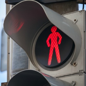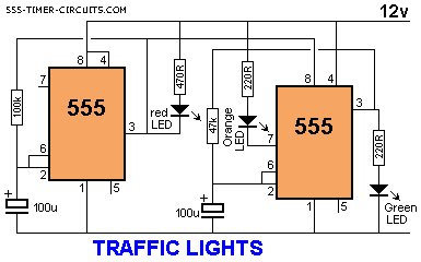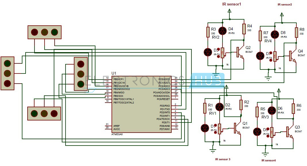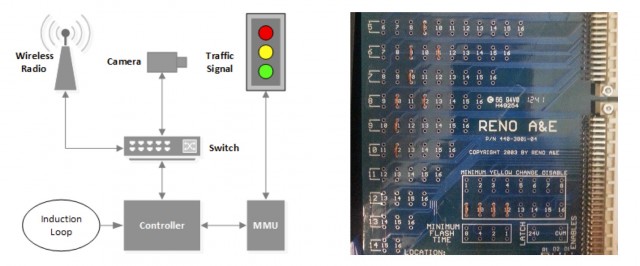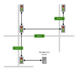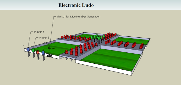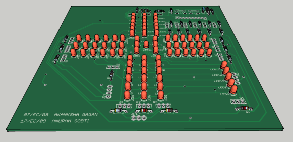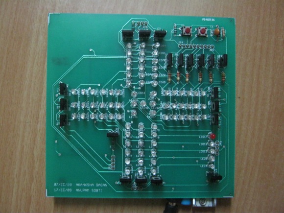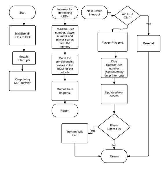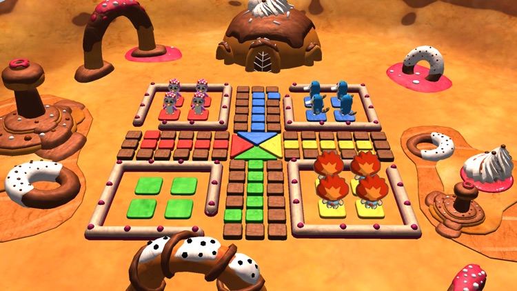
Roll of the dice is not a probability theory but a theory of certainty if done in tempo: 0 --- 50 --- 100 --- 150 ---- 200 --- etc times a throw. rene decartes --- newton --- einstein ( ReNeEinstein ) analyzes the dice in 6 box blocks which are paired together into the shape of a cube usually in game ludo used 2 pieces of dice thrown simultaneously while in the traffic light intersection intersection that can turn left and right using the 3 dice theorem in alternating settings. in the Bible there are many insights about the dice but not the lottery dice for example in the book of revelation where there are 12 precious stones as the foundation of the decline of this heavenly kingdom is represented by the throwing of 2 pieces of the dice with a definite value of 4 doors after descending to earth.
XXX . XXX Dice
Dice ( singular die or dice; from Old French dé; from Latin datum "something which is given or played" ) are small throw able objects with multiple resting positions, used for generating random numbers. Dice are suitable as gambling devices for games like craps and are also used in non-gambling tabletop games.
A traditional die is a cube, with each of its six faces showing a different number of dots (pips) from 1 to 6. When thrown or rolled, the die comes to rest showing on its upper surface a random integer from one to six, each value being equally likely. A variety of similar devices are also described as dice; such specialized dice may have polyhedral or irregular shapes and may have faces marked with symbols instead of numbers. They may be used to produce results other than one through six. Loaded and crooked dice are designed to favor some results over others for purposes of cheating or amusement.
A dice tray, a tray used to contain thrown dice, is sometimes used for gambling or board games, in particular to allow dice throws which do not interfere with other game pieces.
Flash Back
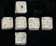
Dice have been used since before recorded history, and it is uncertain where they originated. The oldest known dice were excavated as part of a backgammon-like game set at the Burnt City, an archeological site in south-eastern Iran, estimated to be from between 2800–2500 BC.[3] Other excavations from ancient tombs in the Indus Valley civilization indicate a South Asian origin.[4]
The Egyptian game of Senet was played with dice. Senet was played before 3000 BC and up to the 2nd century AD. It was likely a racing game, but there is no scholarly consensus on the rules of Senet.[5] Dicing is mentioned as an Indian game in the Rigveda, Atharvaveda and the early Buddhist games list.There are several biblical references to "casting lots", as in Psalm 22, indicating that dicing (or a related activity) was commonplace when the psalm was composed. It is theorized that dice developed from the practice of fortunetelling with the talus of hoofed animals, colloquially known as "knucklebones", but knucklebones is not the oldest divination technique that incorporates randomness. Knucklebones was a game of skill played by women and children; a derivative form had the four sides of the bone receive different values and count as modern dice.
Although gambling was illegal, many Romans were passionate gamblers who enjoyed dicing, which was known as aleam ludere ("to play at dice"). Dicing was even a popular pastime of emperors. Letters by Augustus to Tacitus and his daughter recount his hobby of dicing. There were two sizes of Roman dice. Tali were large dice inscribed with one, three, four, and six on four sides. Tesserae were smaller dice with sides numbered from one to six.[9] Twenty-sided dice date back to the 2nd century AD[10] and from Ptolemaic Egypt as early as the 2nd century BC.[11]
Dominoes and playing cards originated in China as developments from dice. The transition from dice to playing cards occurred in China around the Tang dynasty, and coincides with the technological transition from rolls of manuscripts to block printed books. In Japan, dice were used to play a popular game called sugoroku. There are two types of sugoroku. Ban-sugoroku is similar to backgammon and dates to the Heian period, while e-sugoroku is a racing game.
Usage
Dice are thrown onto a flat surface either from the hand or from a container designed for this (such as a dice cup). The face of the die that is uppermost when it comes to rest provides the value of the throw. One typical dice game today is craps, where two dice are thrown simultaneously and wagers are made on the total value of the two dice. Dice are frequently used to randomize moves in board games, usually by deciding the distance through which a piece will move along the board; examples of this are backgammon and Monopoly.
The result of a die roll is determined by the way it is thrown, according to the laws of classical mechanics. A die roll is made random by uncertainty in minor factors such as tiny movements in the thrower's hand; they are thus a crude form of hardware random number generator. Perhaps to mitigate against concerns that the pips on the faces of certain styles of dice cause a small bias,casinos use precision dice with flush markings.
Construction
Arrangement
Common dice are small cubes most commonly 1.6 cm (0.63 in) across, whose faces are numbered from one to six, usually by patterns of round dots called pips. (While the use of Hindu-Arabic numerals is occasionally seen, such dice are less common.)
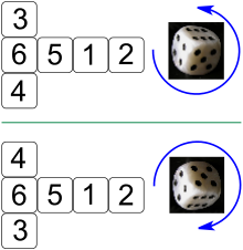
Opposite sides of a modern die traditionally add up to seven, implying that the 1, 2 and 3 faces share a vertex. The faces of a die may be placed clockwise or counterclockwise about this vertex. If the 1, 2 and 3 faces run counterclockwise, the die is called "right-handed", and if those faces run clockwise, the die is called "left-handed". Western dice are normally right-handed, and Chinese dice are normally left-handed.
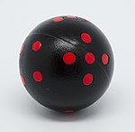
The pips on dice are arranged in specific patterns as shown. Asian style dice bear similar patterns to Western ones, but the pips are closer to the center of the face; in addition, the pips are differently sized on Asian style dice, and the pips are colored red on the 1 and 4 sides. One possible explanation is that red fours are of Indian origin. In some older sets, the "one" pip is a colorless depression.
Manufacturing
Non-precision dice are manufactured via the plastic injection molding process. The pips or numbers on the die are a part of the mold. The coloring for numbering is achieved by submerging the die entirely in paint, which is allowed to dry. The die is then polished via a tumble finishing process similar to rock polishing. The abrasive agent scrapes off all of the paint except for the indents of the numbering. A finer abrasive is then used to polish the die. This process also creates the smoother, rounded edges on the dice.[18]
Precision casino dice may have a polished or sand finish, making them transparent or translucent respectively. Casino dice have their pips drilled, then filled flush with a paint of the same density as the material used for the dice, such that the center of gravity of the dice is as close to the geometric center as possible. All such dice are stamped with a serial number to prevent potential cheaters from substituting a die. Precision backgammon dice are made the same way; they tend to be slightly smaller and have rounded corners and edges, to allow better movement inside the dice cup and stop forceful rolls from damaging the playing surface.
Terms
While the terms ace, deuce, trey, cater, cinque and sice are generally obsolete, with the names of the numbers preferred, they are still used by some professional gamblers to designate different sides of the dice. Ace is from the Latin as, meaning "a unit"; the others are 2 to 6 in Old French.
Unicode representation
Using Unicode characters, the faces ⚀ ⚁ ⚂ ⚃ ⚄ ⚅, can be shown in text using the range U+2680 to U+2685 or using decimal
⚀ to ⚅.Loaded dice
A loaded, weighted, or crooked die is one that has been tampered with so that it will land with a specific side facing upwards more or less often than a fair die would. There are several methods for creating loaded dice, including rounded faces, off-square faces and weights. Transparent cellulose acetate dice are used by casinos as tampering is more apparent than with opaque dice.
Variants
Polyhedral dice
Around the end of the 1960s, non-cubical dice became popular among players of wargames,and since have been employed extensively in role-playing games and trading card games. The numerals 6 and 9, which are reciprocally symmetric through rotation, are distinguished with a dot or underline.
Standard variations
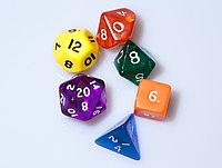
Dice are often sold in sets, matching in color, of six different shapes. Five of the dice are shaped like the Platonic solids, whose faces are regular polygons. Aside from the cube, the other four Platonic solids have 4, 8, 12, and 20 faces, allowing for those number ranges to be generated. The only other common non-cubical die is the 10-sided die, a pentagonal trapezohedron die, whose faces are ten kites, each with two different edge lengths, three different angles, and two different kinds of vertices. Such sets frequently include a second 10-sided die either of contrasting color or numbered by tens, allowing for a pair of 10-sided dice to generate numbers between 1 and 100.
Using these dice in various ways, games can closely approximate the real probability distributions of the events they simulate. For instance, 10-sided dice can be rolled in pairs to produce a uniform distribution of random percentages, and summing the values of multiple dice will produce approximations to normal distributions.[23]
Unlike other common dice, a four-sided die does not have a side that faces upward when it is at rest on a surface, so it has to be read in a different way. Many such dice have the numbers printed around the points, so that when it settles, the numbers at the vertex pointing up are the same and are read. Alternatively, the numbers on a tetrahedral die can be placed at the middles of the edges, in which case the numbers around the base are read.
Normally, the faces on a die will be placed so opposite faces will add up to one more than the number of faces (this is not possible with 4-sided dice and dice with an odd-number of faces). Some dice, such as those with 10 sides, are usually numbered sequentially beginning with 0, in which case the opposite faces will add to one less than the number of faces.
| Faces/ Sides | Shape | Notes | |
|---|---|---|---|
| 4 | Tetrahedron | Each face has three numbers, arranged such that the upright number, placed either near the vertex or near the opposite edge, is the same on all three visible faces. The upright numbers represent the value of the roll. This die does not roll well and thus it is usually thrown into the air instead. | |
| 6 | Cube | A common die. The sum of the numbers on opposite faces is seven. | |
| 8 | Octahedron | Each face is triangular and the die resembles two square pyramids attached base-to-base. Usually, the sum of the opposite faces is 9. | |
| 10 | Pentagonal trapezohedron | Each face is a kite. The die has two sharp corners, where five kites meet, and ten blunter corners, where three kites meet. The ten faces usually bear numbers from zero to nine, rather than one to ten (zero being read as "ten" in many applications). Often all odd numbered faces converge at one sharp corner, and the even ones at the other. The sum of the numbers on opposite faces is usually 9 (if numbered 0–9) or 11 (if numbered 1–10). | |
| 12 | Dodecahedron | Each face is a regular pentagon. The sum of the numbers on opposite faces is usually 13. | |
| 20 | Icosahedron | Faces are equilateral triangles. Icosahedrons have been found dating to Roman/Ptolemaic times, but it is not known if they were used as gaming dice. Modern dice with 20 sides are sometimes numbered 0–9 twice as an alternative to 10-sided dice. The sum of the numbers on opposite faces is 21 if numbered 1–20. | |
Rarer variations
"Uniform fair dice" are dice where all faces have equal probability of outcome, which follows from the symmetry of the die (as it is face-transitive), and include:
- Platonic solids, the five regular polyhedra: 4, 6, 8, 12, 20 sides
- Catalan solids, the duals of the 13 Archimedean solids: 12, 24, 30, 48, 60, 120 sides
- Bipyramids, the duals of the infinite set of prisms, with triangle faces: any multiple of 4 (so that a face will face up) above 8
- Trapezohedrons, the duals of the infinite set of antiprisms, with kite faces: any even number not divisible by 4 (so that a face will face up) above 6
- Disphenoids, an infinite set of tetrahedra made from congruent non-regular triangles: 4 sides
A variation on the standard die is known as the "average" die.[24][25] These are six-sided dice with sides numbered
2, 3, 3, 4, 4, 5, which have the same arithmetic mean as a standard die (3.5 for a single die, 7 for a pair of dice), but have a narrower range of possible values (2 through 5 for one, 4 through 10 for a pair). They are used in some table-top wargames, where a narrower range of numbers is required.[25]
Dice with an odd number of flat faces can be made as "long dice".[26] They are based on an infinite set of prisms. All the (rectangular) faces they may actually land on are congruent, so they are equally fair. (The other 2 sides of the prism are rounded or capped with a pyramid, designed so that the die never actually rests on those faces.)
| Faces/ sides | Shape | Image | Notes |
|---|---|---|---|
| 1 | Möbius strip or sphere | Most commonly a joke die, this is either a sphere with a 1 marked on it or shaped like a Möbius strip. | |
| 2 | Cylinder | A coin flip. Some coins with 1 marked on one side and 2 on the other are available, but most simply use a common coin. | |
| 3 | Rounded-off triangular prism | This is a rounded-off triangular prism, intended to be rolled like a rolling-pin style die. The die is rounded-off at the edges to make it impossible for it to somehow land on the triangular sides, which makes it look a bit like a jewel. When the die is rolled, one edge (rather than a side) appears facing upwards. On either side of each edge the same number is printed (from 1 to 3). The numbers on either side of the up-facing edge are read as the result of the die roll. | |
| 5 | Triangular prism | This is a prism that is thin enough to land either on its "edge" or "face". When landing on an edge, the result is displayed by digits (2–4) close to the prism's top edge. The triangular faces are labeled with the digits 1 and 5. | |
| 7 | Pentagonal prism | Similar in constitution to the 5-sided die. Seven-sided dice are used in a seven-player variant of backgammon. Seven-sided dice are described in the 13th century Libro de los juegos as having been invented by Alfonso X in order to speed up play in chess variants.[27][28] | |
| 12 | Rhombic dodecahedron | Each face is a rhombus. | |
| 14 | Heptagonal trapezohedron | Each face is a kite. | |
| 16 | Octagonal bipyramid | Each face is an isosceles triangle. | |
| 18 | Rounded rhombicuboctahedron | 18 faces are squares; the 8 triangular faces are rounded and cannot be landed on. | |
| 24 | Triakis octahedron | Each face is an isosceles triangle. | |
| Tetrakis hexahedron | Each face is an isosceles triangle. | ||
| Deltoidal icositetrahedron | Each face is a kite. | ||
| Pentagonal icositetrahedron | Each face is an irregular pentagon. | ||
| 30 | Rhombic triacontahedron | Each face is a rhombus. Although not included in most dice sets, it can be found in most hobby and game stores. | |
| 34 | Heptadecagonal trapezohedron | Each face is a kite. | |
| 48 | Disdyakis dodecahedron | Each face is a scalene triangle. | |
| 50 | Icosakaipentagonal trapezohedron | The faces of the 50-sided die are kites, although very narrow. | |
| 60 | Deltoidal hexecontahedron | Each face is a kite. | |
| Pentakis dodecahedron | Each face is an isosceles triangle. | ||
| Pentagonal hexecontahedron | Each face is an irregular pentagon. | ||
| Triakis icosahedron | Each face is an isosceles triangle. | ||
| 100 | Zocchihedron | 100-sided dice can be found in hobby and game stores. They are made by flattening 100 facets on a sphere, but are not truly "uniform fair dice". | |
| 120 | Disdyakis triacontahedron | Each face is a scalene triangle. |
Non-numeric
The faces of most dice are labelled using sequences of whole numbers, usually starting at one, expressed with either pips or digits. However, there are some applications that require results other than numbers. Examples include letters for Boggle, directions for Warhammer Fantasy Battle, Fudge dice, playing card symbols for poker dice, and instructions for sexual acts using sex dice.
Spherical dice
A die can be constructed in the shape of a sphere, with the addition of an internal cavity in the shape of the dual polyhedron of the desired die shape and an internal weight. The weight will settle in one of the points of the internal cavity, causing it to settle with one of the numbers uppermost. For instance, a sphere with an octahedral cavity and a small internal weight will settle with one of the 6 points of the cavity held downwards by the weight.
Applications
Polyhedral dice are commonly used in role-playing games. The fantasy role-playing game Dungeons & Dragons (D&D) is largely credited with popularizing dice in such games. Some games use only one type, like Exalted which uses only ten-sided dice. Others use numerous types for different game purposes, such as D&D, which makes use of all common polyhedral dice. Dice are usually used to determine the outcome of events. Games typically determine results either as a total on one or more dice above or below a fixed number, or a certain number of rolls above a certain number on one or more dice. Due to circumstances or character skill, the initial roll may have a number added to or subtracted from the final result, or have the player roll extra or fewer dice. To keep track of rolls easily, dice notation is frequently used.
Many board games use dice to randomize how far pieces move or to settle conflicts. Typically, this has meant that rolling higher numbers is better. Some games, such as Axis & Allies, have inverted this system by making the lower values more potent. In the modern age, a few games and game designers have approached dice in a different way by making each side of the die similarly valuable. In Castles of Burgundy, players spend their dice to take actions based on the die's value. In this game, a six is not better than a one, or vice versa. In Quarriors (and its descendent, Dicemasters), different sides of the dice can offer completely different abilities. Several sides often give resources while others grant the player useful actions.
Dice can be used for divination and using dice for such a purpose is called cleromancy. A pair of common dice is usual, though other forms of polyhedra can be used. Tibetan Buddhists sometimes use this method of divination. It is highly likely that the Pythagoreans used the Platonic solids as dice. They referred to such dice as "the dice of the gods" and they sought to understand the universe through an understanding of geometry in polyhedra.
Astrological dice are a specialized set of three 12-sided dice for divination; the first die represents planets, the Sun, the Moon, and the nodes of the Moon, the second die represents the 12 zodiac signs, and the third represents the 12 houses. A specialized icosahedron die provides the answers of the Magic 8-Ball, conventionally used to provide answers to yes-or-no questions.
Notation
In many gaming contexts, especially tabletop role-playing games, shorthand notations representing different dice rolls are used. A "d" or "D" is used to indicate a die with a specific number of sides; for example,
d4 denotes a four-sided die. If several dice of the same type are to be rolled, this is indicated by a leading number specifying the number of dice. Hence, 6d8 means the player should roll six eight-sided dice and add the results. Modifiers to a die roll can also be indicated as desired. For example, 3d6+4 instructs the player to roll three six-sided dice, calculate the total, and add four to it. Fuzzy dice
Fuzzy dice, also known as fluffy dice or soft dice, are an automotive decoration consisting of two oversized (usually six-sided) plush dice which hang from the rear-view mirror. The original fuzzy dice, first used in the 1950s, were white and approximately 3 inches (8 cm) across. Nowadays, fuzzy dice come in many colors (including fluorescents, with bright pink or blue being popular) and are available in many sizes. In Britain and other parts of the world it is considered kitsch to display such items in a car.
Origin and histor
The use of fuzzy dice is believed to be traced back to American fighter pilots during World War II. Pilots would hang the dice above their instruments displaying seven pips before a 'sortie' mission for good luck. It is also speculated that the dice represented a high degree of risk associated with the fighter sorties; hundreds of pilots were shot down each week. Upon returning after the war, many airmen continued the tradition.
In the 1950s, the fuzzy dice became one of the first items sold specifically to be hung from a rear-view mirror. Ed Sundberg and Lupe Zavala claim to have started the trend in 1959 at Deccofelt Corp. in Glendora, CA. Their dice were made of polyurethane squares with felt dots. When dice were produced in other countries, designers adopted a "fuzzy" plush material.
It has been postulated that the late Mark Shepherd Jr., a former CEO of Texas Instruments, created the first fuzzy dice in 1952, when he was a project engineer working for the company. He supposedly made them as a "good luck" gag gift for a professional acquaintance, knowing the original use of the dice.
A 1993 study found no correlation between the use of fuzzy dice and the degree of a driver's reckless driving behavior

A pair of fuzzy dice
Sicherman dice
Sicherman dice /ˈsɪkərmən/ are the only pair of 6-sided dice that are not normal dice, bear only positive integers, and have the same probability distribution for the sum as normal dice.
The faces on the dice are numbered 1, 2, 2, 3, 3, 4 and 1, 3, 4, 5, 6, 8.
Mathematics
A standard exercise in elementary combinatorics is to calculate the number of ways of rolling any given value with a pair of fair six-sided dice (by taking the sum of the two rolls). The table shows the number of such ways of rolling a given value :
| n | 2 | 3 | 4 | 5 | 6 | 7 | 8 | 9 | 10 | 11 | 12 |
| # of ways | 1 | 2 | 3 | 4 | 5 | 6 | 5 | 4 | 3 | 2 | 1 |
Crazy dice is a mathematical exercise in elementary combinatorics, involving a re-labeling of the faces of a pair of six-sided dice to reproduce the same frequency of sums as the standard labeling. The Sicherman dice are crazy dice that are re-labeled with only positive integers.
The table below lists all possible totals of dice rolls with standard dice and Sicherman dice. One Sicherman die is coloured for clarity: 1–2–2–3–3–4, and the other is all black, 1–3–4–5–6–8.
| 2 | 3 | 4 | 5 | 6 | 7 | 8 | 9 | 10 | 11 | 12 | |
| Standard dice | 1+1 | 1+2 2+1 | 1+3 2+2 3+1 | 1+4 2+3 3+2 4+1 | 1+5 2+4 3+3 4+2 5+1 | 1+6 2+5 3+4 4+3 5+2 6+1 | 2+6 3+5 4+4 5+3 6+2 | 3+6 4+5 5+4 6+3 | 4+6 5+5 6+4 | 5+6 6+5 | 6+6 |
| Sicherman dice | 1+1 | 2+1 2+1 | 3+1 3+1 1+3 | 1+4 2+3 2+3 4+1 | 1+5 2+4 2+4 3+3 3+3 | 1+6 2+5 2+5 3+4 3+4 4+3 | 2+6 2+6 3+5 3+5 4+4 | 1+8 3+6 3+6 4+5 | 2+8 2+8 4+6 | 3+8 3+8 | 4+8 |
Flash Back
The Sicherman dice were discovered by George Sicherman of Buffalo, New York and were originally reported by Martin Gardner in a 1978 article in Scientific American.
The numbers can be arranged so that all pairs of numbers on opposing sides sum to equal numbers, 5 for the first and 9 for the second.
Later, in a letter to Sicherman, Gardner mentioned that a magician he knew had anticipated Sicherman's discovery. For generalizations of the Sicherman dice to more than two dice and noncubical dice, see Broline (1979), Gallian and Rusin (1979), Brunson and Swift (1997/1998), and Fowler and Swift (1999).
Mathematical justification
Let a canonical n-sided die be an n-hedron whose faces are marked with the integers [1,n] such that the probability of throwing each number is 1/n. Consider the canonical cubical (six-sided) die. The generating function for the throws of such a die is . The product of this polynomial with itself yields the generating function for the throws of a pair of dice: . From the theory of cyclotomic polynomials, we know that
where d ranges over the divisors of n and is the d-th cyclotomic polynomial. We note also that
- .
We therefore derive the generating function of a single n-sided canonical die as being
and is canceled. Thus the factorization of the generating function of a six-sided canonical die is
The generating function for the throws of two dice is the product of two copies of each of these factors. How can we partition them to form two legal dice whose spots are not arranged traditionally? Here legal means that the coefficients are non-negative and sum to six, so that each die has six sides and every face has at least one spot. (That is, the generating function of each die must be a polynomial p(x) with positive coefficients, and with p(0) = 0 and p(1) = 6.) Only one such partition exists:
and
This gives us the distribution of spots on the faces of a pair of Sicherman dice as being {1,2,2,3,3,4} and {1,3,4,5,6,8}, as above.
This technique can be extended for dice with an arbitrary number of sides.
d 20 System
The d20 System is a role-playing game system published in 2000 by Wizards of the Coast originally developed for the third edition of Dungeons & Dragons. The system is named after the 20-sided dice which are central to the core mechanics of many actions in the game.
Much of the d20 System was released as the System Reference Document (SRD) under the Open Game License (OGL) as Open Game Content (OGC), which allows commercial and non-commercial publishers to release modifications or supplements to the system without paying for the use of the system's associated intellectual property, which is owned by Wizards of the Coast.
The original impetus for the open licensing of the d20 System was the economics of producing role playing games. Game supplements suffered far more diminished sales over time than the core books required to play the game. Ryan Dancey, Dungeons & Dragons' brand manager at the time, directed the effort of licensing the new edition of Dungeons & Dragons through the 'd20 System Trademark', allowing other companies to support the d20 System under a common brand identity. This is distinct from the Open Game License, which simply allows any party to produce works composed of or derivative from designated Open Game Content.
Mechanics
The d20 System is a derivative of the third edition Dungeons & Dragons game system. The three primary designers behind the d20 System were Jonathan Tweet, Monte Cook and Skip Williams; many others contributed, most notably Richard Baker and Wizards of the Coast then-president Peter Adkison. Many give Tweet the bulk of the credit for the basic resolution mechanic, citing similarities to the system behind his game Ars Magica. Tweet, however, stated "The other designers already had a core mechanic similar to the current one when I joined the design team".[2]
To resolve an action in the d20 System, a player rolls a 20-sided die and adds modifiers based on the natural aptitude of the character (defined by six abilities: Strength, Dexterity, Constitution, Intelligence, Wisdom, and Charisma) and how skilled the character is in various fields (such as in combat), as well as other, situational modifiers.[3] If the result is greater than or equal to a target number (called a Difficulty Class or DC) then the action succeeds. This is called the Core Mechanic. This system is consistently used for all action resolution in the d20 System: in prior games in the D&D family, the rules for different actions, such as the first-edition hit tables or the second-edition AD&D "THAC0" and saving throw mechanics, varied considerably in which dice were used and even whether high numbers or low numbers were preferable.
The d20 System is not presented as a universal system in any of its publications or free distributions, unlike games like GURPS. Rather, the core system has been presented in a variety of formats that have been adapted by various publishers (both Wizards of the Coast and third-party) to specific settings and genres, much like the Basic Role-Playing system common to early games by veteran RPG publisher Chaosium.
The rules for the d20 System are defined in the System Reference Document or SRD (two separate SRDs were released, one for D&D 3rd edition and one for edition 3.5), which may be copied freely or even sold.[4]Designed for fantasy-genre games in (usually) a pseudo-medieval setting, the SRD is drawn from the Dungeons & Dragons books Player's Handbook v3.5, Expanded Psionics Handbook, Dungeon Master's Guide v3.5, Monster Manual v3.5, Deities and Demigods v3.0, Unearthed Arcana, and Epic Level Handbook. Information from these books not in the SRD include detailed descriptions, flavor-text, and material Wizards of the Coast considers Product Identity (such as references to the Greyhawk campaign setting and information on mind flayers).
d20 Modern has its own SRD, called the Modern System Reference Document (MSRD). The MSRD includes material from the d20 Modern roleplaying game, Urban Arcana Campaign Setting, the d20 Menace Manual, and d20 Future; this can cover a wide variety of genres, but is intended for a modern-day, or in the case of the last of these, a futuristic setting.
Flash Back
Development
Ryan Dancey believed that the strength of Dungeons & Dragons was in its gaming community instead of its game system, which supported his belief in Skaff Elias's axiom known as the "Skaff Effect" which suggested that other companies only enhanced the success of the RPG market leader, which was now Wizards of the Coast. Dancey also theorized that the proliferation of game systems weakened the RPG industry, and these beliefs led to the idea to let other publishers create supplements for D&D.[5]:287 This led to a pair of licenses released by Wizards in 2000, prior to the release of third edition D&D: the Open Gaming License (OGL) made the D&D third-edition mechanics permanently open and available for use as a set of "system reference documents", while the d20 Trademark License built on this by letting publishers use Wizards' official "d20" mark to show that their products were compatible. Unlike the OGL, the d20 License was written so that it could be cancelled at some point in the future.
2000-2003: d20 boom
Initially there was a boom in the RPG industry caused by the d20 license, with numerous companies producing their own d20 supplements. Some companies used the d20 system to try to boost the sales of their own proprietary systems, including Atlas Games and Chaosium, while many more publishers exclusively produced d20 content, including older companies such as Alderac Entertainment, Fantasy Flight Games, and White Wolf, and new companies like Goodman Games, Green Ronin, Mongoose Publishing, and Troll Lord Games. The success of the d20 license helped to launch the RPG PDF industry; there was a demand for d20 products and electronic delivery offered players a very quick and cheap way to distribute content.
Wizards also began using their new d20 system for more than just fantasy games, including the Star Wars Roleplaying Game (2000) and the d20 Modern Roleplaying Game (2002). Wizards developed one of d20 Modern's setting into a full sourcebook: the Urban Arcana Campaign Setting (2003), and extended d20 even further with the science-fiction d20 Future (2004) and the historical d20 Past (2005), and closed out the line in 2006 with another campaign setting, Dark•Matter (2006) for d20 Modern.[5]:292 Third-party publishers used these d20 genre books as the basis of their own campaign settings too, and White Wolf even used the d20 Modern rules to publish a licensed version of Gamma World (2006) as well as a few supplements.
2003-: 3.5 edition and d20 bust
Wizards of the Coast felt that a sexual roleplaying book might damage their own brand, so before the Valar Project could publish their Book of Erotic Fantasy (2003), Wizards quickly changed the d20 license to require that publications meet "community standards of decency"; Valar simply moved their book over to the OGL. This event caused other d20 publishers to realize how much control Wizards had over them.
At Gen Con 36, in August 2003, Wizards published the new version 3.5 of Dungeons & Dragons. Though the changes from the third edition were small, there were enough changes that it was somewhat difficult for Game Masters to precisely update a 3rd edition book to 3.5. The effect on the d20 market was disastrous: third-party publishers had very little warning of the update and so some books were out-of-date as soon as they were published, and Wizards did not offer any update for the d20 trademark. Many d20 publishers went out of business and many others left the field, but most of those who remained abandoned the d20 trademark entirely, publishing instead under the OGL. Publishers realized that they could publish d20 games that did not depend upon Wizards of the Coast's core books, and publishers even began to create direct competitors to D&D using the OGL.[5]:293
Trademark license
Because Dungeons & Dragons is the most popular role-playing game in the world,[6][7] many third party publishers of the 2000s produced products designed to be compatible with that game and its cousin, d20 Modern. Wizards of the Coast provided a separate license allowing publishers to use some of its trademarked terms and a distinctive logo to help consumers identify these products. This was known as the "d20 System Trademark License".
The d20 System Trademark License (D20STL) required publishers to exclude character creation and advancement rules, apply certain notices and adhere to an acceptable content policy. D20STL products were also required to clearly state that they require the core books from Wizards of the Coast for use. All D20STL products also had to use the OGL to make use of d20 System open content, but publishers were able to use the OGL without using the D20STL. Games that only use the OGL were (and are) not bound by these restrictions, and several have included character creation and advancement rules, allowing them to be used as standalone products.
With the release of the 4th edition of Dungeons & Dragons in 2008, Wizards of the Coast revoked the original D20STL, replacing it with a new license specifically for D&D, known as the Game System License. The terms of this license are similar to the D20STL, but there is no associated OGL or Open Content, and the fourth edition SRD merely lists the items and terms which may be used in licensed products. This did not affect the legal standing of the OGL, and products based on the SRD may still be released under the OGL alone.
Criticisms
Unlike the OGL, the D20STL is revocable and is controlled by Wizards of the Coast. Wizards of the Coast has the ability to alter the d20 System Trademark License at will and gives a short, 30-day "cure period" to rectify any issues with the license before termination. These changes apply retroactively to all material published under the d20 System Trademark License.
Book of Erotic Fantasy and 2003 change
When gaming company The Valar Project, under former Wizards of the Coast brand manager Anthony Valtera, attempted to publish the d20 Book of Erotic Fantasy (BoEF), which focused on sexual content, Wizards of the Coast altered the d20 System Trademark License in advance of publication of BoEF by adding a "quality standards" provision that required publishers comply with "community standards of decency." This subsequently prevented the book's publication under the D20STL.[9] Wizards of the Coast said this was done to protect its d20 System trademark. The Book of Erotic Fantasy was subsequently published without the d20 System trademark under the OGL. Other books subsequently published under similar circumstances include Skirmisher Publishing LLC's Nuisances which also includes on its cover the disclaimer "Warning: Intended For Mature Readers Only."
The same round of changes to the license also limited the size at which the text "Requires the use of the Dungeons & Dragons Player's Handbook, Third Edition, published by Wizards of the Coast" (which is required to appear on the front or back cover of most fantasy d20 System products) could be printed, and prohibited making part of it larger than the rest. This was perceived as being aimed at the same Valar book; early mockups of the cover had the words "Dungeons & Dragons" in the above text printed much larger and in a different font from the rest, right at the top of the front cover. This could have made the book appear to be an official Dungeons & Dragons publication to a casual or uninformed observer. The published version does not have the offending text on the cover.
Other criticisms
Criticism is also levied at the conditions for termination of the d20 System Trademark License through a breach of its terms. The license requires that, upon breach of the terms of the D20STL which includes any subsequent modifications of the license after publication of a work using the d20 System trademark, all inventory and marketing material must be destroyed. Adhering to the breach conditions is an onerous task for smaller game companies. The mere threat of this condition being imposed was a huge blow to the now defunct d20 System publisher Fast Forward Entertainment, which had released several books that used non-open Wizards of the Coast content due to company president James Ward's misunderstanding of the license.
Other criticism is based around the part of the d20 System Trademark License which defines "Open Game Content" to include game mechanics and purports to license it. It is widely believed that game mechanics are uncopyrightable in the USA, and according to a circular on the US Copyright Office's website,[11] "Once a game has been made public, nothing in the copyright law prevents others from developing another game based on similar principles."
One result of this has been the abandonment of the d20 System License by some publishers in favor of a simple "OGL" designation. Mongoose Publishing's licensed games based on the Conan the Barbarian property (Conan: The Roleplaying Game) and the Robert A. Heinlein novel Starship Troopers, for example, use systems that function nearly identically to d20 but do not carry the d20 logo.
XXX . XXX 4% zero null 0 Electronic Dice Circuit
7 Segment Simple Electronic Dice
Dice or die is a throw able object which is majorly used in gambling as a device to generate random numbers. It is a rounded cube with six outer surfaces with numbers or dots ranging from one to six on each face.
The concept of electronic dice using 555 timer is also similar to a normal dice, but instead of using a hard dice having six outer surfaces with dots or numbers on each face of the dice, the electronic dice is made up of Light Emitting Diodes, astable oscillator circuit, a counter and a display driver. The electronic die effectively generates random numbers by displaying the number of LED’s which is similar to a normal die – when it is thrown and settles down to rest with one surface facing upwards – it displays a particular number or dots.
Block Diagram of Electronic Dice
The block diagram of an electronic dice consists of a BCD counter, a seven-segment LED display, a 555 timer and a BCD to 7-segment decoder which are connected as shown in the below figure along with different blocks.
555 Timer as Astable Multivibrator
A 555 timer is majorly used IC for oscillator applications, timer and as a multivibrator for pulse generation. The 555 timer in astable mode generates continuous pulses with a particular frequency. As shown in the figure, one resistor is connected between the Vcc and the discharge pin, another resistor is connected between the discharge pin and the trigger pin/threshold pin. The pin 2 and pin 6 are connected together such that the circuit triggers itself for every cycle of operation such that it is termed as a free-running oscillator.
The frequency of the generated pulse depends on the values of the resistors and capacitor in the above circuit and the frequency is given by
F= 1/T
Where T= cycle time= T1+T2
Where T= cycle time= T1+T2
Hence, it is also termed as a free-running oscillator because without providing the triggering this circuit is capable of generating the output.
The charging and discharging times can be given as follows:
T1= 0.693(R1+R2)*C and T2=0.693*R2*C
Thus, frequency can be given as
F= 1.44/((R1+2*R2)*C)
The capacitor in the above circuit, charges through R1 and R2, and discharges through R2 resistor, which is connected to the discharge pin.
BCD Counter
As shown in the figure, the 4510 Binary Coded Decimal counter consists of four outputs and can count up or down according to the inputs logic if pulses are delivered to a clock input. The BCD follows sequence 0000 to 1001 (the binary equivalent of decimal number 0 to 9) after that the next pulse resets the counter and again repeats from 0000 to 1001. It consists of four synchronously clocked D-flip-flops.
BCD to 7 Segment Decoder
The output must be able to drive the 7-segment display, so for converting the BCD to 7-segment outputs that can drive the 7-segment display, an IC 4511B used as a converter. This IC consists of four input lines and seven output lines and a few extra control lines as shown in the figure.
The state of the segment outputs Qa to Qg can be determined by the data on D0 to D3 if the LE is LOW and the ripple banking is HIGH.
If LE goes HIGH, then the data present on D0 to D3 is stored in latches, while there will be no change in the segments’ outputs.
7 Segment Display
The 7-segment display is an electronic device used for displaying the decimal numerals which are widely used in digital clocks and many other applications.
This device can be developed by using an LCD or LED for display purpose. The device can be differentiated based on the cathodes or anodes of the LEDs used in the device. If all the cathodes are connected to a common pin, then it is termed as a common cathode device, and if all the anodes are connected to a common pin, then it is termed as a common anode device.
Electronic Dice Circuit Working
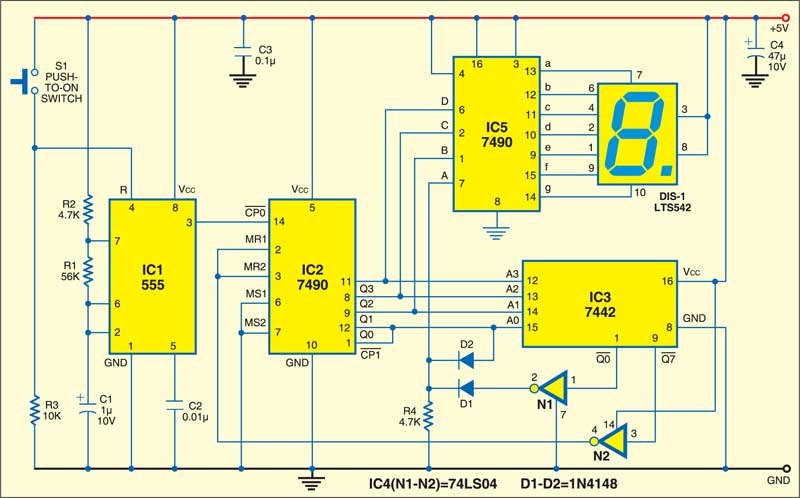
The block diagram of the electronic dice project is shown in the above figure at the beginning of the article and this circuit represents the internal circuit diagram of the electronic dice. If the switch is pushed, then the 555 timer connected as astable oscillator will generate the pulses with very-high frequencies. These pulses are driven to the IC connected to the 555 timer in the circuit and the counter counts from 0 to 9 in normal applications, but here for the electronic dice the counter counts form 0 to 5, and then the counter gets reset by using the reset pin of the IC. Again the counting cycle repeats from 0 to 5.
However, for better outputs, we need to make it as 1 to 6 instead of 0 to 5, and for this purpose we need one code conversion unit between the counter and the decoder, which is as shown in the circuit. The conversion unit consists of NOR gates in which the two gates are connected with the diodes and resistors which are termed as 4025 IC.
As we know that if all the inputs of the NOR gates are LOW, then the outputs of the NOR gates will be HIGH, such that the DIODE’s will be having the values of anode greater than the cathode. Thus, the DIODE’s will become forward biased, even though the outputs B and C are HIGH, the 10kΩ resistor makes the input to remain LOW by limiting the current flow between the outputs and inputs.
Then, the 4511 IC will be connected to the 7 segment display by using the seven 560Ω resistors to each pin of the display. These resistors are used in series for the protection of 7 segment display by limiting the current. The seven-segment display used in the circuit is a common cathode display as we have discussed earlier that there are common cathode and common anode seven-segment displays.
Hence, as we push the button, the count will be displayed by the 7 seven segment display, and will disappear after some time. Thus, by pushing the switch of the circuit, the electronic dice displays the number from 1 to 6 based on the count given by the counter, and then it is processed by the entire circuit as discussed above.
If the frequency of the 555 timer astable oscillator is very high, then the time period will be very less – then the Light Emitting Diodes operation will not be sufficient for prediction through observation as the time period will be of very short duration, that is, about a few microseconds (if we consider a frequency of 5kHz, then the time period will be 0.0002 seconds, which cannot be observed by a normal human eye).
