a key is often made for someone's privacy both for the living room and study room as well as the sex room ^ _ ^ also the main money-box when we need the key of course we need the tools and materials to open it in manual locks that are moved by the human hand can be made key by the result mechanical machine wipes between the key and lock containers; in key electronics is considered as a key to the memory of electronic circuit components, the key to memory can be represented using electronic components called transistors, diodes, and ICs of both linear ICs, timer ICs and digital ICs; component component electronics process above that is the component that replaces the gear gear manual on the mechanical lock that is between the mechanical container and the mechanical opening key. in the electronics locking system a lot of instrumentation and control tools that can be made as electronic locks, electronic key locks are arranged either using an input transducer (sensor) that produces an efficient and effective transducer output (actuator) while the process of connecting the key (sensor) and the key container (actuator) is called an efficient and effective process component; the process component may use semi-conductor electronic means and materials; optical fiber optic apparatus and materials; magnetic electronic appliance and materials; tools and electronic materials pneumatic controller; appliance and electronic material of super conductor; electron mechanical tools and materials; and transponder electronic devices and materials while the memory and key genetic codes can use many analog and digital coding techniques and dynamic controls and other triggering triggering techniques that may one day be described in my book {GO LOOK IMPORTANTBOOK}
Electronic lock
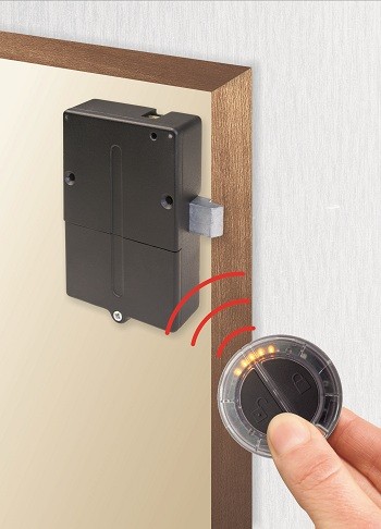
An electronic lock (or electric lock) is a locking device which operates by means of electric current. Electric locks are sometimes stand-alone with an electronic control assembly mounted directly to the lock. Electric locks may be connected to an access control system, the advantages of which include: key control, where keys can be added and removed without re-keying the lock cylinder; fine access control, where time and place are factors; and transaction logging, where activity is recorded. Electronic locks can also be remotely monitored and controlled, both to lock and unlock.

A quick demonstration of an electronic door lock
Operation
Electric locks use magnets, solenoids, or motors to actuate the lock by either supplying or removing power. Operating the lock can be as simple as using a switch, for example an apartment intercom door release, or as complex as a bio metric based access control system.
There are two basic types of locks: "preventing mechanism" or operation mechanism .
Types
Electromagnetic lock
 A deadbolt electronic lock mounted in a home safe
The most basic type of electronic lock is a magnetic lock (informally called a "mag lock"). A large electro-magnet is mounted on the door frame and a corresponding armature is mounted on the door. When the magnet is powered and the door is closed, the armature is held fast to the magnet. Mag locks are simple to install and are very attack-resistant. One drawback is that improperly installed or maintained mag locks can fall on people, and also that one must unlock the mag lock to both enter and to leave. This has caused fire marshals to impose strict rules on the use of mag locks and access control practice in general. Additionally, NFPA 101 (Standard for Life Safety and Security), as well as the ADA (Americans with Disability Act) require "no prior knowledge" and "one simple movement" to allow "free egress". This means that in an emergency, a person must be able to move to a door and immediately exit with one motion (requiring no push buttons, having another person unlock the door, reading a sign, or "special knowledge").
Other problems include a lag time (delay), because the collapsing magnetic field holding the door shut does not release instantaneously. This lag time can cause a user to collide with the still-locked door. Finally, mag locks fail unlocked, in other words, if electrical power is removed they unlock. This could be a problem where security is a primary concern. Additionally, power outages could affect mag locks installed on fire listed doors, which are required to remain latched at all times except when personnel are passing through. Most mag lock designs would not meet current fire codes as the primary means of securing a fire listed door to a frame. Because of this, many commercial doors (this typically does not apply to private residences) are moving over to stand-alone locks, or electric locks installed under a Certified Personnel Program.
The first mechanical recodable card lock was invented in 1976 by Tor Sørnes, who had worked for VingCard since the 1950s. The first card lock order was shipped in 1979 to Westin Peachtree Plaza Hotel, Atlanta, US. This product triggered the evolution of electronic locks for the hospitality industry.
Electronic strikes
Electric strikes (also called electric latch release) replace a standard strike mounted on the door frame and receive the latch and latch bolt. Electric strikes can be simplest to install when they are designed for one-for-one drop-in replacement of a standard strike, but some electric strike designs require that the door frame be heavily modified. Installation of a strike into a fire listed door (for open backed strikes on pairs of doors) or the frame must be done under listing agency authority, if any modifications to the frame are required (mostly for commercial doors and frames). In the US, since there is no current Certified Personnel Program to allow field installation of electric strikes into fire listed door openings, listing agency field evaluations would most likely require the door and frame to be de-listed and replaced.
Electric strikes can allow mechanical free egress: a departing person operates the lockset in the door, not the electric strike in the door frame. Electric strikes can also be either "fail unlocked" (except in Fire Listed Doors, as they must remain latched when power is not present), or the more-secure "fail locked" design. Electric strikes are easier to attack than a mag lock. It is simple to lever the door open at the strike, as often there is an increased gap between the strike and the door latch. Latch guard plates are often used to cover this gap.
Electronic deadbolts and latches
Electric mortise and cylindrical locks are drop-in replacements for door-mounted mechanical locks. An additional hole must be drilled in the door for electric power wires. Also, a power transfer hinge is often used to get the power from the door frame to the door. Electric mortise and cylindrical locks allow mechanical free egress, and can be either fail unlocked or fail locked. In the US, UL rated doors must retain their rating: in new construction doors are cored and then rated. but in retrofits, the doors must be re-rated.
Electrified exit hardware, sometimes called "panic hardware" or "crash bars", are used in fire exit applications. A person wishing to exit pushes against the bar to open the door, making it the easiest of mechanically-free exit methods. Electrified exit hardware can be either fail unlocked or fail locked. A drawback of electrified exit hardware is their complexity, which requires skill to install and maintenance to assure proper function. Only hardware labeled "Fire Exit Hardware" can be installed on fire listed doors and frames and must meet both panic exit listing standards and fire listing standards.
Motor-operated locks are used throughout Europe. A European motor-operated lock has two modes, day mode where only the latch is electrically operated, and night mode where the more secure deadbolt is electrically operated.
In South Korea, most homes and apartments have installed electronic locks, which are currently replacing the lock systems in older homes. South Korea mainly uses a lock system by Gateman.
Authentication methods
A feature of electronic locks is that the locks can deactivated or opened by authentication, without the use of a traditional physical key:
Numerical codes, passwords, and passphrases
Perhaps the most common form of electronic lock uses a keypad to enter a numerical code or password for authentication. Such locks typically provide, and some feature an audible response to each press. Combination lengths are usually between 4 and 6 digits long.
Security tokens
Another means of authenticating users is to require them to scan or "swipe" a security token such as a smart card or similar, or to interact a token with the lock. For example, some locks can access stored credentials on a personal digital assistant (PDA) or smartphone, by using infrared, Bluetooth, or NFC data transfer methods.
Biometrics
As biometrics become more and more prominent as a recognized means of positive identification, their use in security systems increases. Some electronic locks take advantage of technologies such as fingerprint scanning, retinal scanning, iris scanning and voice print identification to authenticate users.
RFID
Radio-frequency identification (RFID) is the use of an object (typically referred to as an "RFID tag") applied to or incorporated into a product, animal, or person for the purpose of identification and tracking using radio waves. Some tags can be read from several meters away and beyond the line of sight of the reader. This technology is also used in some modern electronic locks.
XXX . XXX Access control
In the fields of physical security and information security, access control (AC) is the selective restriction of access to a place or other resource. The act of accessing may mean consuming, entering, or using. Permission to access a resource is called authorization.
Locks and login credentials are two analogous mechanisms of access control.
 A sailor allows a driver to enter a military installation.
 Physical security
Geographical access control may be enforced by personnel (e.g., border guard, bouncer, ticket checker), or with a device such as a turnstile. There may be fences to avoid circumventing this access control. An alternative of access control in the strict sense (physically controlling access itself) is a system of checking authorized presence, see e.g. Ticket controller (transportation). A variant is exit control, e.g. of a shop (checkout) or a country.
The term access control refers to the practice of restricting entrance to a property, a building, or a room to authorized persons. Physical access control can be achieved by a human (a guard, bouncer, or receptionist), through mechanical means such as locks and keys, or through technological means such as access control systems like the mantrap. Within these environments, physical key management may also be employed as a means of further managing and monitoring access to mechanically keyed areas or access to certain small assets.
Physical access control is a matter of who, where, and when. An access control system determines who is allowed to enter or exit, where they are allowed to exit or enter, and when they are allowed to enter or exit. Historically, this was partially accomplished through keys and locks. When a door is locked, only someone with a key can enter through the door, depending on how the lock is configured. Mechanical locks and keys do not allow restriction of the key holder to specific times or dates. Mechanical locks and keys do not provide records of the key used on any specific door, and the keys can be easily copied or transferred to an unauthorized person. When a mechanical key is lost or the key holder is no longer authorized to use the protected area, the locks must be re-keyed.
Electronic access control uses computers to solve the limitations of mechanical locks and keys. A wide range of credentials can be used to replace mechanical keys. The electronic access control system grants access based on the credential presented. When access is granted, the door is unlocked for a predetermined time and the transaction is recorded. When access is refused, the door remains locked and the attempted access is recorded. The system will also monitor the door and alarm if the door is forced open or held open too long after being unlocked.
Access control system operation
When a credential is presented to a reader, the reader sends the credential’s information, usually a number, to a control panel, a highly reliable processor. The control panel compares the credential's number to an access control list, grants or denies the presented request, and sends a transaction log to a database. When access is denied based on the access control list, the door remains locked. If there is a match between the credential and the access control list, the control panel operates a relay that in turn unlocks the door. The control panel also ignores a door open signal to prevent an alarm. Often the reader provides feedback, such as a flashing red LED for an access denied and a flashing green LED for an access granted.
The above description illustrates a single factor transaction. Credentials can be passed around, thus subverting the access control list. For example, Alice has access rights to the server room, but Bob does not. Alice either gives Bob her credential, or Bob takes it; he now has access to the server room. To prevent this, two-factor authentication can be used. In a two factor transaction, the presented credential and a second factor are needed for access to be granted; another factor can be a PIN, a second credential, operator intervention, or a bio metric input.
There are three types (factors) of authenticating information:
- something the user knows, e.g. a password, pass-phrase or PIN
- something the user has, such as smart card or a key fob
- something the user is, such as fingerprint, verified by bio metric measurement
Passwords are a common means of verifying a user's identity before access is given to information systems. In addition, a fourth factor of authentication is now recognized: someone you know, whereby another person who knows you can provide a human element of authentication in situations where systems have been set up to allow for such scenarios. For example, a user may have their password, but have forgotten their smart card. In such a scenario, if the user is known to designated cohorts, the cohorts may provide their smart card and password, in combination with the extant factor of the user in question, and thus provide two factors for the user with the missing credential, giving three factors overall to allow access.
Credential
A credential is a physical/tangible object, a piece of knowledge, or a facet of a person's physical being that enables an individual access to a given physical facility or computer-based information system. Typically, credentials can be something a person knows (such as a number or PIN), something they have (such as an access badge), something they are (such as a bio metric feature), or some combination of these items. This is known as multi-factor authentication. The typical credential is an access card or key-fob, and newer software can also turn users' smartphones into access devices.
There are many card technologies including magnetic stripe, bar code, Wiegand, 125 kHz proximity, 26-bit card-swipe, contact smart cards, and contact less smart cards. Also available are key-fobs, which are more compact than ID cards, and attach to a key ring. Bio metric technologies include fingerprint, facial recognition, iris recognition, retinal scan, voice, and hand geometry. The built-in bio metric technologies found on newer smartphones can also be used as credentials in conjunction with access software running on mobile devices.[4] In addition to older more traditional card access technologies, newer technologies such as Near field communication (NFC) and Bluetooth low energy also have potential to communicate user credentials to readers for system or building access.
Access control system components
An access control point can be a door, turnstile, parking gate, elevator, or other physical barrier, where granting access can be electronically controlled. Typically, the access point is a door. An electronic access control door can contain several elements. At its most basic, there is a stand-alone electric lock. The lock is unlocked by an operator with a switch. To automate this, operator intervention is replaced by a reader. The reader could be a keypad where a code is entered, it could be a card reader, or it could be a bio metric reader. Readers do not usually make an access decision, but send a card number to an access control panel that verifies the number against an access list. To monitor the door position a magnetic door switch can be used. In concept, the door switch is not unlike those on refrigerators or car doors. Generally only entry is controlled, and exit is uncontrolled. In cases where exit is also controlled, a second reader is used on the opposite side of the door. In cases where exit is not controlled, free exit, a device called a request-to-exit (REX) is used. Request-to-exit devices can be a push-button or a motion detector. When the button is pushed, or the motion detector detects motion at the door, the door alarm is temporarily ignored while the door is opened. Exiting a door without having to electrically unlock the door is called mechanical free egress. This is an important safety feature. In cases where the lock must be electrically unlocked on exit, the request-to-exit device also unlocks the door.
Access control topology
Access control decisions are made by comparing the credential to an access control list. This look-up can be done by a host or server, by an access control panel, or by a reader. The development of access control systems has seen a steady push of the look-up out from a central host to the edge of the system, or the reader. The predominant topology circa 2009 is hub and spoke with a control panel as the hub, and the readers as the spokes. The look-up and control functions are by the control panel. The spokes communicate through a serial connection; usually RS-485. Some manufactures are pushing the decision making to the edge by placing a controller at the door. The controllers are IP enabled, and connect to a host and database using standard networks.
Types of readers
Access control readers may be classified by the functions they are able to perform:
- Basic (non-intelligent) readers: simply read card number or PIN, and forward it to a control panel. In case of biometric identification, such readers output the ID number of a user. Typically, Wiegand protocol is used for transmitting data to the control panel, but other options such as RS-232, RS-485 and Clock/Data are not uncommon. This is the most popular type of access control readers. Examples of such readers are RF Tiny by RFLOGICS, ProxPoint by HID, and P300 by Farpointe Data.
- Semi-intelligent readers: have all inputs and outputs necessary to control door hardware (lock, door contact, exit button), but do not make any access decisions. When a user presents a card or enters a PIN, the reader sends information to the main controller, and waits for its response. If the connection to the main controller is interrupted, such readers stop working, or function in a degraded mode. Usually semi-intelligent readers are connected to a control panel via an RS-485 bus. Examples of such readers are InfoProx Lite IPL200 by CEM Systems, and AP-510 by Apollo.
- Intelligent readers: have all inputs and outputs necessary to control door hardware; they also have memory and processing power necessary to make access decisions independently. Like semi-intelligent readers, they are connected to a control panel via an RS-485 bus. The control panel sends configuration updates, and retrieves events from the readers. Examples of such readers could be InfoProx IPO200 by CEM Systems, and AP-500 by Apollo. There is also a new generation of intelligent readers referred to as "IP readers". Systems with IP readers usually do not have traditional control panels, and readers communicate directly to a PC that acts as a host.
Some readers may have additional features such as an LCD and function buttons for data collection purposes (i.e. clock-in/clock-out events for attendance reports), camera/speaker/microphone for intercom, and smart card read/write support.
Access control readers may also be classified by their type of identification technology.
Access control system topologies
1. Serial controllers. Controllers are connected to a host PC via a serial RS-485 communication line (or via 20mA current loop in some older systems). External RS-232/485 converters or internal RS-485 cards have to be installed, as standard PCs do not have RS-485 communication ports.
Advantages:
- RS-485 standard allows long cable runs, up to 4000 feet (1200 m)
- Relatively short response time. The maximum number of devices on an RS-485 line is limited to 32, which means that the host can frequently request status updates from each device, and display events almost in real time.
- High reliability and security as the communication line is not shared with any other systems.
Disadvantages:
- RS-485 does not allow Star-type wiring unless splitters are used
- RS-485 is not well suited for transferring large amounts of data (i.e. configuration and users). The highest possible throughput is 115.2 kbit/sec, but in most system it is downgraded to 56.2 kbit/sec, or less, to increase reliability.
- RS-485 does not allow the host PC to communicate with several controllers connected to the same port simultaneously. Therefore, in large systems, transfers of configuration, and users to controllers may take a very long time, interfering with normal operations.
- Controllers cannot initiate communication in case of an alarm. The host PC acts as a master on the RS-485 communication line, and controllers have to wait until they are polled.
- Special serial switches are required, in order to build a redundant host PC setup.
- Separate RS-485 lines have to be installed, instead of using an already existing network infrastructure.
- Cable that meets RS-485 standards is significantly more expensive than regular Category 5 UTP network cable.
- Operation of the system is highly dependent on the host PC. In the case that the host PC fails, events from controllers are not retrieved, and functions that require interaction between controllers (i.e. anti-passback) stop working.
2. Serial main and sub-controllers. All door hardware is connected to sub-controllers (a.k.a. door controllers or door interfaces). Sub-controllers usually do not make access decisions, and instead forward all requests to the main controllers. Main controllers usually support from 16 to 32 sub-controllers.
Advantages:
- Work load on the host PC is significantly reduced, because it only needs to communicate with a few main controllers.
- The overall cost of the system is lower, as sub-controllers are usually simple and inexpensive devices.
- All other advantages listed in the first paragraph apply.
Disadvantages:
- Operation of the system is highly dependent on main controllers. In case one of the main controllers fails, events from its sub-controllers are not retrieved, and functions that require interaction between sub-controllers (i.e. anti-passback) stop working.
- Some models of sub-controllers (usually lower cost) do not have the memory or processing power to make access decisions independently. If the main controller fails, sub-controllers change to degraded mode in which doors are either completely locked or unlocked, and no events are recorded. Such sub-controllers should be avoided, or used only in areas that do not require high security.
- Main controllers tend to be expensive, therefore such a topology is not very well suited for systems with multiple remote locations that have only a few doors.
- All other RS-485-related disadvantages listed in the first paragraph apply.
3. Serial main controllers & intelligent readers. All door hardware is connected directly to intelligent or semi-intelligent readers. Readers usually do not make access decisions, and forward all requests to the main controller. Only if the connection to the main controller is unavailable, will the readers use their internal database to make access decisions and record events. Semi-intelligent reader that have no database and cannot function without the main controller should be used only in areas that do not require high security. Main controllers usually support from 16 to 64 readers. All advantages and disadvantages are the same as the ones listed in the second paragraph.
4. Serial controllers with terminal servers. In spite of the rapid development and increasing use of computer networks, access control manufacturers remained conservative, and did not rush to introduce network-enabled products. When pressed for solutions with network connectivity, many chose the option requiring less efforts: addition of a terminal server, a device that converts serial data for transmission via LAN or WAN.
Advantages:
- Allows utilizing the existing network infrastructure for connecting separate segments of the system.
- Provides a convenient solution in cases when the installation of an RS-485 line would be difficult or impossible.
Disadvantages:
- Increases complexity of the system.
- Creates additional work for installers: usually terminal servers have to be configured independently, and not through the interface of the access control software.
- Serial communication link between the controller and the terminal server acts as a bottleneck: even though the data between the host PC and the terminal server travels at the 10/100/ 1000Mbit /sec network speed, it must slow down to the serial speed of 112.5 kbit/sec or less. There are also additional delays introduced in the process of conversion between serial and network data.
All the RS-485-related advantages and disadvantages also apply.
5. Network-enabled main controllers. The topology is nearly the same as described in the second and third paragraphs. The same advantages and disadvantages apply, but the on-board network interface offers a couple of valuable improvements. Transmission of configuration and user data to the main controllers is faster, and may be done in parallel. This makes the system more responsive, and does not interrupt normal operations. No special hardware is required in order to achieve redundant host PC setup: in the case that the primary host PC fails, the secondary host PC may start polling network controllers. The disadvantages introduced by terminal servers (listed in the fourth paragraph) are also eliminated.
6. IP controllers. Controllers are connected to a host PC via Ethernet LAN or WAN.
Advantages:
- An existing network infrastructure is fully utilized, and there is no need to install new communication lines.
- There are no limitations regarding the number of controllers (as the 32 per line in cases of RS-485).
- Special RS-485 installation, termination, grounding and troubleshooting knowledge is not required.
- Communication with the controllers may be done at the full network speed, which is important if transferring a lot of data (databases with thousands of users, possibly including bio metric records).
- In case of an alarm, controllers may initiate connection to the host PC. This ability is important in large systems, because it serves to reduce network traffic caused by unnecessary polling.
- Simplifies installation of systems consisting of multiple sites that are separated by large distances. A basic Internet link is sufficient to establish connections to the remote locations.
- Wide selection of standard network equipment is available to provide connectivity in various situations (fiber, wireless, VPN, dual path, PoE)
Disadvantages:
- The system becomes susceptible to network related problems, such as delays in case of heavy traffic and network equipment failures.
- Access controllers and workstations may become accessible to hackers if the network of the organization is not well protected. This threat may be eliminated by physically separating the access control network from the network of the organization. Also it should be noted that most IP controllers utilize either Linux platform or proprietary operating systems, which makes them more difficult to hack. Industry standard data encryption is also used.
- Maximum distance from a hub or a switch to the controller (if using a copper cable) is 100 meters (330 ft).
- Operation of the system is dependent on the host PC. In case the host PC fails, events from controllers are not retrieved and functions that require interaction between controllers (i.e. anti-passback) stop working. Some controllers, however, have a peer-to-peer communication option in order to reduce dependency on the host PC.
7. IP readers. Readers are connected to a host PC via Ethernet LAN or WAN.
Advantages:
- Most IP readers are PoE capable. This feature makes it very easy to provide battery backed power to the entire system, including the locks and various types of detectors (if used).
- IP readers eliminate the need for controller enclosures.
- There is no wasted capacity when using IP readers (e.g. a 4-door controller would have 25% of unused capacity if it was controlling only 3 doors).
- IP reader systems scale easily: there is no need to install new main or sub-controllers.
- Failure of one IP reader does not affect any other readers in the system.
Disadvantages:
- In order to be used in high-security areas, IP readers require special input/output modules to eliminate the possibility of intrusion by accessing lock and/or exit button wiring. Not all IP reader manufacturers have such modules available.
- Being more sophisticated than basic readers, IP readers are also more expensive and sensitive, therefore they should not be installed outdoors in areas with harsh weather conditions, or high probability of vandalism, unless specifically designed for exterior installation. A few manufacturers make such models.
The advantages and disadvantages of IP controllers apply to the IP readers as well.
Security risks
The most common security risk of intrusion through an access control system is by simply following a legitimate user through a door, and this is referred to as tailgating. Often the legitimate user will hold the door for the intruder. This risk can be minimized through security awareness training of the user population, or more active means such as turnstiles. In very high security applications this risk is minimized by using a sally port, sometimes called a security vestibule or mantrap, where operator intervention is required presumably to assure valid identification.
The second most common risk is from levering a door open. This is relatively difficult on properly secured doors with strikes or high holding force magnetic locks. Fully implemented access control systems include forced door monitoring alarms. These vary in effectiveness, usually failing from high false positive alarms, poor database configuration, or lack of active intrusion monitoring. Most newer access control systems incorporate some type of door prop alarm to inform system administrators of a door left open longer than a specified length of time.
The third most common security risk is natural disasters. In order to mitigate risk from natural disasters, the structure of the building, down to the quality of the network and computer equipment vital. From an organizational perspective, the leadership will need to adopt and implement an All Hazards Plan, or Incident Response Plan. The highlights of any incident plan determined by the National Incident Management System must include pre-incident planning, during incident actions, disaster recovery, and after action review.
Similar to levering is crashing through cheap partition walls. In shared tenant spaces the divisional wall is a vulnerability. A vulnerability along the same lines is the breaking of sidelights.
Spoofing locking hardware is fairly simple and more elegant than levering. A strong magnet can operate the solenoid controlling bolts in electric locking hardware. Motor locks, more prevalent in Europe than in the US, are also susceptible to this attack using a doughnut shaped magnet. It is also possible to manipulate the power to the lock either by removing or adding current, although most Access Control systems incorporate battery back-up systems and the locks are almost always located on the secure side of the door.
Access cards themselves have proven vulnerable to sophisticated attacks. Enterprising hackers have built portable readers that capture the card number from a user’s proximity card. The hacker simply walks by the user, reads the card, and then presents the number to a reader securing the door. This is possible because card numbers are sent in the clear, no encryption being used. To counter this, dual authentication methods, such as a card plus a PIN should always be used.
Many access control credentials unique serial numbers are programmed in sequential order during manufacturing. Known as a sequential attack, if an intruder has a credential once used in the system they can simply increment or decrement the serial number until they find a credential that is currently authorized in the system. Ordering credentials with random unique serial numbers is recommended to counter this threat.
Finally, most electric locking hardware still have mechanical keys as a fail-over. Mechanical key locks are vulnerable to bumping.
The need-to-know principle
The need to know principle can be enforced with user access controls and authorization procedures and its objective is to ensure that only authorized individuals gain access to information or systems necessary to undertake their duties.
Computer security
In computer security, general access control includes authentication, authorization, and audit. A more narrow definition of access control would cover only access approval, whereby the system makes a decision to grant or reject an access request from an already authenticated subject, based on what the subject is authorized to access. Authentication and access control are often combined into a single operation, so that access is approved based on successful authentication, or based on an anonymous access token. Authentication methods and tokens include passwords, bio metric scans, physical keys, electronic keys and devices, hidden paths, social barriers, and monitoring by humans and automated systems.
In any access-control model, the entities that can perform actions on the system are called subjects, and the entities representing resources to which access may need to be controlled are called objects ( Access Control Matrix). Subjects and objects should both be considered as software entities, rather than as human users: any human users can only have an effect on the system via the software entities that they control.
Although some systems equate subjects with user IDs, so that all processes started by a user by default have the same authority, this level of control is not fine-grained enough to satisfy the principle of least privilege, and arguably is responsible for the prevalence of malware in such systems (see computer insecurity).
In some models, for example the object-capability model, any software entity can potentially act as both subject and object.
As of 2014, access-control models tend to fall into one of two classes: those based on capabilities and those based on access control lists (ACLs).
- In a capability-based model, holding an unforgeable reference or capability to an object provides access to the object (roughly analogous to how possession of one's house key grants one access to one's house); access is conveyed to another party by transmitting such a capability over a secure channel
- In an ACL-based model, a subject's access to an object depends on whether its identity appears on a list associated with the object (roughly analogous to how a bouncer at a private party would check an ID to see if a name appears on the guest list); access is conveyed by editing the list. (Different ACL systems have a variety of different conventions regarding who or what is responsible for editing the list and how it is edited.)
Both capability-based and ACL-based models have mechanisms to allow access rights to be granted to all members of a group of subjects (often the group is itself modeled as a subject).
Access control systems provide the essential services of authorization, identification and authentication (I&A), access approval, and accountability where:
- authorization specifies what a subject can do
- identification and authentication ensure that only legitimate subjects can log on to a system
- access approval grants access during operations, by association of users with the resources that they are allowed to access, based on the authorization policy
- accountability identifies what a subject (or all subjects associated with a user) did
Access control models
Access to accounts can be enforced through many types of controls.
- Attribute-based Access Control (ABAC)
An access control paradigm whereby access rights are granted to users through the use of policies which evaluate attributes (user attributes, resource attributes and environment conditions) - Discretionary Access Control (DAC)
In DAC, the data owner determines who can access specific resources. For example, a system administrator may create a hierarchy of files to be accessed based on certain permissions. - History-Based Access Control (HBAC)
Access is granted or declined based on the real-time evaluation of a history of activities of the inquiring party, e.g. behavior, time between requests, content of requests.[12] For example, the access to a certain service or data source can be granted or declined on the personal behavior, e.g. the request interval exceeds one query per second. - Identity-Based Access Control (IBAC)
Using this network administrators can more effectively manage activity and access based on individual needs. - Mandatory Access Control (MAC)
In MAC, users do not have much freedom to determine who has access to their files. For example, security clearance of users and classification of data (as confidential, secret or top secret) are used as security labels to define the level of trust. - Organization-Based Access control (OrBAC)
OrBAC model allows the policy designer to define a security policy independently of the implementation - Role-Based Access Control (RBAC)
RBAC allows access based on the job title. RBAC largely eliminates discretion when providing access to objects. For example, a human resources specialist should not have permissions to create network accounts; this should be a role reserved for network administrators. - Rule-Based Access Control (RAC)
RAC method is largely context based. Example of this would be only allowing students to use the labs during a certain time of day. - Responsibility Based Access control
Information is accessed based on the responsibilities assigned to an actor or a business role[15]
Telecommunication
In telecommunication, the term access control is defined in U.S. Federal Standard 1037C with the following meanings:
- A service feature or technique used to permit or deny use of the components of a communication system.
- A technique used to define or restrict the rights of individuals or application programs to obtain data from, or place data onto, a storage device.
- The definition or restriction of the rights of individuals or application programs to obtain data from, or place data into, a storage device.
- The process of limiting access to the resources of an AIS (Automated Information System) to authorized users, programs, processes, or other systems.
- That function performed by the resource controller that allocates system resources to satisfy user requests.
This definition depends on several other technical terms from Federal Standard 1037C.
In object-oriented programming
In object-oriented programming languages, access control is a part of the apparatus of achieving encapsulation, one of four fundamentals of object-oriented programming. The goal is to establish a clear separation between interface (visible and accessible parts of the class) and implementation (internal representation and helper methods).
Also known as data hiding, it ensures exclusive data access to class members (both variables and methods) and protects object integrity by preventing corruption by a client programmer/ client classes. Rule of thumb is to use the more restrictive access level for your data, unless there is a compelling reason to expose it. This also helps to reduce inter dependencies between classes - leading to lower coupling and fewer regression bugs.[
In object-oriented programming, access control is typically implemented using access modifiers in the object or class. Although access modifiers may be syntactically different between languages, they all attempt to achieve the same goal; Define which variables and methods are visible and to whom.
Several programming languages (e.g. Java, C++, C#, Ruby) use the same public, protected and private access modifiers. These are the keywords which allow a programmer to establish access levels to classes and class members (both data and methods). Their exact use in each programming language is varied, depending on the language philosophy, but there are more similarities than differences.
Comparison of use of access modifier keywords in different OOP languages
| Keyword | C++ | Java | Ruby | C# |
|---|---|---|---|---|
private | class | class | - | class |
protected | derived classes | derived classes and/or within same package | derived classes | derived class |
package | - | within its package | - | - |
internal | - | - | - | current assembly |
public | everybody | everybody | everybody | everybody |
| no modifier (default) | class | same package | everybody | class |
Note: in Ruby, private methods always have self as an implicit receiver. Therefore, they can only be used on their current object.
In some languages there are mechanisms to override access modifies to gain access to the private components of an object. One such example is the friend class in C++.
Attribute accessors
Special public member methods - accessors (aka getters) and mutator methods (often called setters) are used to control changes to class variables in order to prevent unauthorized access and data corruption.
Public policy
In public policy, access control to restrict access to systems ("authorization") or to track or monitor behavior within systems ("accountability") is an implementation feature of using trusted systems for security or social control.
Security lighting
Planning considerations
Security lighting can be counter-productive. Turning off lights halved the number of thefts and burglary in Övertorneå Sweden. A test in West Sussex UK showed that adding all-night lighting in some areas made people there feel safer, although crime rates increased 55% in those areas compared to control areas and to the county as a whole.
| “ | In the early seventies, the public-school system in San Antonio, Texas, began leaving many of its school buildings, parking lots, and other property dark at night and found that the no-lights policy not only reduced energy costs but also dramatically cut vandalism. | ” |
Bright, unshielded floodlights often prevent people from noticing criminal activity, and help criminals see what they are doing.
While adequate lighting around a physical structure is deployed to reduce the risk of an intrusion, it is critical that the lighting be designed carefully as poorly arranged lighting can create glare which actually obstructs vision. Studies have shown that many criminals are aware of this effect and actively exploit it. The optimal design will also depend on whether the area will be watched directly by humans or by closed-circuit television, and on the location of the observers or cameras.
Security lighting may be subject to vandalism, possibly to reduce its effectiveness for a subsequent intrusion attempt. Thus security lights should either be mounted very high, or else protected by wire mesh or tough polycarbonate shields. Other lamps may be completely recessed from view and access, with the light directed out through a light pipe or reflected from a polished aluminium or stainless steel mirror. For similar reasons high security installations may provide a stand-by power supply for their security lighting.
Some typical considerations include:
- Reduce and prevent glare and situations mentioned above
- Shielded or full cut-off (FCO) lamp housings which conceal the bulb could be used, which should direct light onto the ground or target and away from observers. These lights should send no light above 80 degrees from the nadir. Lighting should be bright enough, and not "as bright as possible". In many cases a good rule of thumb is 0.5 watts per square metre (0.05 watts per square foot). This might need to be increased in very confused environments, but conversely can be reduced in very open environments. Multiple lamps of moderate power instead of a few powerful lamps will reduce glare, provide more even illumination with reduced pools of shadow, and provide some redundancy if one lamp's bulb blows out or develops a bad ballast.
- Prevent malicious tampering or interference. This means that besides the lamp itself, the entire circuit from the source (electric company or generator), through the wires, to the lamp and back should be protected.
- Luminaires should be accessible so that the maintainer can replace blown bulbs as quickly as possible and clean the luminaires periodically. However they should be protected or somehow made inaccessible to tampering.
- Ensure the electric meter box is locked or inaccessible, or else power the lights from a different line.
- Control and power lines, where outside or vulnerable, should be either buried well underground (in conduits preferably) or at a height of at least 8 metres (about 24 feet).
- Ideally multiple circuits should be used to prevent an accidental or malicious short or cut causing all illumination to fail.
Use
Security lighting can be used in residential, commercial, industrial, institutional, and military settings. Some examples of security lighting include floodlights and low pressure sodium vapour lights. Most lights intended to be left on all night are high-intensity discharge lamps as these have good energy efficiency, thus reducing the cost of running a lamp for such long periods.
A disadvantage of low pressure sodium lamps is that the colour is pure yellow, so the illuminated scene is seen without any colour differentiation. Consequently, high pressure sodium vapour lamps (which are still yellowish, but closer to golden white) are also used, at the cost of greater running expenses and increased light pollution. High pressure sodium lamps also take slightly longer to restrike after a power interruption.
Other lights may be activated by sensors such as passive infrared sensors (PIRs), turning on only when a person (or other mammal) approaches. PIR activated lamps will usually be incandescent bulbs so that they can activate instantly; energy saving is less important since they will not be on all the time. PIR sensor activation can increase both the deterrent effect (since the intruder knows that he has been detected) and the detection effect (since a person will be attracted to the sudden increase in light). Some PIR units can be set up to sound a chime as well as turn on the light. Most modern units have a photocell so that they only turn on when it is dark.
Limitations
An important limitation to the usefulness of security lighting is the simple fact that it is only useful at night. This is particularly significant for home owners because, contrary to a widespread myth, most household burglaries occur during the day, when the occupants are away at work or shopping.
As with any lighting, security lighting can reduce night vision, making it harder to see into areas that are unlit or are in shadow.
XXX . XXX 4% Differences between Transponder and Remote Control Keys
The traditional flat metal key that is used to open nearly every type of lock made is losing its popularity and usefulness, as newer types of locking systems come online. This is especially true in the case of the automotive industry, as new vehicles are now coming equipped with transponder keys, as well as remote control keys. Many people confuse the differences between transponder and remote control keys, and think that they are basically the same, they are not.
What is the Difference between a Transponder and a Remote Control Key?
While most cars today come with remote keys, instead of “just” a traditional flat car key, the latest auto mobile models are equipped with key-less transponder locks, thus eliminating the need for physical car keys altogether. The most basic difference between the two is that a transponder unlocks a vehicle without using a physical locking mechanism or key, and the engine will not start without it. A remote key can also unlock the vehicle’s doors, but if the remote control unit does not function, the traditional flat key can be used.
Some types of remote control keys have the remote unit mounted on the head of the key and is basically a separate piece, and others have the remote unit built into/onto the key. If the remote is not functioning, either the battery is dead or the unit is broken, then the remote controlled locking system can be bypassed using the traditional key to unlock the vehicle without causing the alarm to go off.
The main difference is that a remote transponder key has a control chip inside of the unit that is a vital part of a vehicle’s security system, which provides an extra level of anti-theft. Without it, the engine cannot start and the alarm system cannot be disarmed, only an experienced auto locksmith trained in transponder technology can help. High-end cars that are favourite targets for thieves benefit the most from such transponder systems, as it drastically reduces the chance of their vehicle being stolen.
However, there are times that a transponder needs to be maintained, repaired or reprogrammed, and only an authorised auto locksmith can do that because specialised equipment is needed to correctly disarm the security system, and required to reprogram the unique electronic key that will start the vehicle.
Transponder vs Remote
The key that has different size cuts on either a single or double side that match the different size tumblers in the lock. These days it has become a whole lot more involved! Most new cars now come with a Remote Key, so gone are the days of manually unlocking your car… now you can press a button from the other side of the car park.
Remote controlled keys (which come as either remote head keys where the remote is built into the key or fobs where the remote is separate from the key) can unlock and lock your vehicle, and they operate independently from the transponder security system. If your remote key is not working you would need to check that the battery is not flat, or move away from any radio interference (i.e. step closer to the car!) More often than not though cars with remote central locking should have a bypass system using the normal metal key to unlock the doors without setting the alarm off.
These days vehicle keys will also have a transponder microchip embedded into the plastic part of the key – and this is actually part of the vehicle’s anti-theft system. A transponder chip disarms a vehicle immobiliser when the car key is used to start the engine. A European Directive came into place in 1995 enforcing the use of immobilisers on cars in a bid to reduce car theft!
A transponder is short for: transmitter + responder. The transponder microchip has a unique serial number, which is set during its initial programming. When a person wants to start a car, the chip sends a request to the car for it to validate the serial number and turn off the engine immobiliser. If the car doesn’t recognize the number, it will remain immobilised. So, even for a simple car key without any buttons, the key must be cut correctly to turn the locks, and also programmed correctly to disarm the immobiliser – each key is programmed to only start a specific vehicle, which reduces the possibility of theft.
Because of its technology, if you need a copy of your car key and it has a transponder you will need an auto-locksmith as all transponder keys need to be programmed to your car or cloned from an existing key for your vehicle to accept it.
Unfortunately the transponder chips required are not cheap, and an older car will often have a transponder chip which is just as expensive as a newer car.
Anti-Pinch Window Lift Automotive Electronics Project
Good electronics project design references and tips can accelerate your practical know-how in electronics.
Getting good and timely information on the electronic project that you are embarking on sometimes can be time consuming and frustrating. Hence, the objective of this site is to bridge this gap. This site is dedicated to all electronics enthusiasts whether you are a student, a teacher, hobbyist or even an electronics engineer.
The end result of an electronics project is determined by a few factors. It normally starts with the strong enthusiasm in the project chosen, going on to schematic or circuit design, printed circuit board design, software programming if microcontroller is involved and building prototypes.
If you are looking for electronic parts to test your projects, head over to our newly open electronic store and browse the many products that you can purchase.
For many, the process of design ends here when you achieved your objective of creating a useful device or tool that helps you with your daily lives or meeting the objective of the coursework set by the college that you are currently enrolled in.
However, if you want to go further in marketing the product created, a lot of effort is needed in ensuring the reliability of the product. Good design practices, choice of components, reliability test and compliance to standards set by the governing authorities are some of the steps that you will need to take before you can market your product to the public.
This site provides schematics and parts lists of various projects that you can experiment yourself. It also include articles on the importance of reliability testing, electromagnetic compatibility (EMC) testing, failure mode effect and Analysis (FMEA) and fundamental of electronic parts. Test and measurement tools that are needed are also discussed before you embark on your journey of building your own electronic project.
In automotive electronics networking, the commonly networking standard used is called CAN or controller area network which uses a baud rate of up to 1 Mbps. This speed is needed in the control of engine and other critical components of the automobile that requires fast transfer of information.
However, there are some areas of control which does not require that kind of speed and hence a slower speed standard can be utilized to save control cost. Some of these areas are the mirrors control, Window lift, seat control and door lock among others.
Due to this requirements, a consortium was formed in 1998 consisting of 5 automotive manufacturers (Volvo, BMW, Audi, VW and Daimler-Chrysler), 1 tool supplier (VCT) and 1 semiconductor supplier (Motorola) to look into this. As a result, the LIN (Local Interconnect Network) specifications was finalised on 2 February 2000. The first version of LIN was 1.1 and currently version 2.0 is in use. The most recent development in LIN is the use of it over the vehicle's battery line using a DC-LIN transceiver. Some of the main features of LIN are listed below.
- One master and up to 16 slaves. No collision detection feature is needed as master initiated all messages communication with slaves. The master is usually implemented with a more powerful microcontroller compared to the slaves as it has to handle more tasks.
- Baudrate of up to 20kbps. Slower speed is chosen to reduce the effect of electromagnetic interference.
- Single wire implementation based on enhanced ISO 9141.
- Simple SCI or UART hardware interface which is available in most microcontroller chips making its implementation cost effective.
- Self synchronization in the slave nodes without the need to have crystal or ceramic resonator. Internal RC oscillator for the microcontroller is good enough and hence making its implementation lower cost.
Anti-Pinch Window Lift Automotive Electronics Project
One of the LIN application is in the anti-pinch window lift control. The application note from Microchip uses LIN 2.0 protocol in its implementation example.
The micro controller used is PIC16F688, a 14 pin flash based CMOS device with 4096 words program memory, 256 bytes of static RAM, 256 bytes of EEPROM, 12 I/O, 1 8-bit timer, 1 16-bit timer and 8 channels of 10 bit ADC.
A LIN bus transceiver is used for the slave bus driver to connect to network.
Other Automotive Projects
LED Battery Level Indicator Project
This bar graph LED battery level indicator project is based on LM3914 monolithic IC from National Semiconductor that senses the voltage levels of the battery and drives the 10 light emitting diodes based on the voltage level that is detected.
12V Lead Acid Battery Charger
This automotive battery charger project is based on National Semiconductor LM350 3A Adjustable Regulator. It is designed to charge 12V lead acid batteries.
Passive Keyless Entry Project
Most vehicles today have remote controls with two buttons that control the locking and the unlocking of the doors of the vehicles. The development of RFID (Radio Frequency Identification) technology will soon replace this method of opening and closing of the doors.
Automotive Key less Lock
Keyless Lock
Most vehicles today have remote controls with two buttons that control the locking and the unlocking of the doors of the vehicles. The development of RFID (Radio Frequency Identification) technology will soon replace this method of opening and closing of the doors. When a transponder is placed near a reader, it will start to communicate with the reader and once the information exchange is successful, the door will open.
Chances are that you will have seen this technology been implemented on higher end cars these days. It is more convenient and safe as you do not have to scramble for key on your purse or pocket before being able to open the door and after that using the same key to start the engine.
A transponder consists of an antenna with a microchip which is embedded into a plastic tag. It is usually light weight and is designed to take the impact of normal mechanical stress.
When the owner of the vehicle with the transponder in the pocket walks towards the car, the doors of the car will automatically open once the owner is within a few feet from the car. One does not need to search frantically for the remote control of the car in order to open it.
Other features incorporated may include the triggering of lights when the doors opened, auto lock once the owner moves away from the car and other features. Many luxury cars manufacturers have already implemented this keyless lock technology in their vehicles and it is forecast that middle range cars will follow suit soon.
Microchip new PIC16F639 flash MCU which has 3 channel, transponder analog front end and KEELOQ cryptographic peripheral is an ideal microchip to be used in the transponder. The 3 channels has omnidirectional 125kHz low frequency communication that are used to communicate with the base station or the reader. This device can also be used in other wireless authentication applications. An example of the passive keyless entry application circuit is shown below.
The KEELOQ technology is a non linear encryption algorithm that creates a unique transmission on every use, making the capturing and re sending of the same code useless. Hence the security feature is protected from intruders.
This solution from Microchip contains 3 modules. They are the Key Fob, the Base Station and the Receiver/Decoder.
The Base Station starts the communication with the Key Fob by sending out the 125 kHz signal. The Key Fob receives and decodes the challenge from the Base Station. If there is a match, the Key Fob will transmit a 432 MHz signal back to the Receiver/Decoder. If the Receiver/Decoder recognizes the Key Fob as a valid device, it will send out a signal to unlock the door.
What’s the Difference Between a Transponder Key and a Remote?

As a car owner who has previously lost your car keys, you might wonder why it’s quite so expensive and complicated for a dealer to replace the key and we will take some time answering your question today. But first you need to understand that there are two types of automotive keys, namely transponder and non-transponder keys. Transponder keys are not to be confused with automotive remotes. While an auto remove can lock and unlock your car, they operate independently from the transponder security system. Flat car keys on the other hand solely use the mechanical cuts to turn the lock.
The transponder key forms part of the anti-theft security system of the car, and the word is made up of the two terms transmitter and responder. The plastic head of the key picks up signals from the antenna ring around the ignition cylinder and when that happens, the vehicle will operate. Without it however, the vehicle is secure.
Modern transponders use a challenge and password transponder system, which may be encrypted with a rolling code. In this case, the password will change after every use. Using complex mathematical algorithms, the transponder has to crunch the number and respond.
Some cars still use more simplified chip keys that are equipped by identification numbers that are recognizable by the car. Much like an ATM PIN, this key works with the Vehicle Anti Theft System. Such keys are equipped with a resistor and one of fifteen different preset resistances. A key needs to be made using the correct cuts, turn the key cylinder and it must have the correct resistance (Ohm’s) in order for the car to start. If not, it will shut down and lock you out. During lockout, which lasts around 3-4 minutes, not even the correct key will successfully start the car.
What Happens When You Lose Your Transponder Key?
If you need a new transponder key, it has to be programmed, and a locksmith is best placed to do just that. Professional locksmiths combine years of experience with professional-grade equipment to achieve perfect cuts.
Since a car cannot tell the difference between an original key or a cloned copy, it is important to find out which type of transponder key you will get. There are two types, of transponder keys, namely zero bitted, and encrypted. It is important to find a locksmith who owns transponders from all the different car manufacturers, and has the equipment to create a new key for you.
Likewise, it is important to find out whether you can upgrade to a better type of transponder. Some chips require batteries for operation, and others don’t. By choosing one that does not use a battery, you don’t ever have to worry about a battery going flat or leaving you stranded.
Zero bitted keys are meant to be cloned, as they don’t have a preset inscription. These keys are created by inserting your key into a tool before inserting a blank key into the same tool. This way, they can clone your key onto a zero bitted key blank.
Encrypted keys do have a preset, which is a random encryption that needs to be programmed to your car. The locksmith will take a new key to your car, using a tool which hooks up to the car’s OBD port. He will use this tool to add a new, unique and encrypted key to your system. Some brands require all working keys to be present for a new encrypted key to be added, or else they may fall out of the system.
variety of components which enable the locking, organizing and managing of various properties. The systems operate with radio, keyboard, RFID or biometrics.
Actuating Elements
Sensor Elements
XXX . XXX 4 % zero sample transponder
SE transponder
The SE transponder boasts small dimensions and a high-quality design along with a pleasant touch. In addition, it offers maximum functionality.
The "Data on Transponder" version impresses through its large memory capacity. Unlike RFID media, the SE transponder can memorise, in addition to validity periods, a plurality of data thus providing users with maximum flexibility without having to compromise on security.
Apart from transponder groups, up to 65,000 single door authorisations and 500 events can be stored.
The storage of access events and service events such as, for example, the battery states of cylinders and locks are especially useful. The BKS-Key Manager software for managing master key systems clearly displays the current state of a system without having to network its locks and cylinders. In addition, the transponders transmit programming jobs such as disabling transponders and defining new time zones.
Regardless of whether you use mechanical, mechatronic or electronic master key systems – the SE transponder from BKS can be used for any of them. Different cylinders can be combined in a cost-effective overall system. This can be done without having to sacrifice comfort, as all cylinders, keys and transponders are administered and programmed via the BKS-Key Manager software for managing master key systems. Especially efficient master key systems combine the use of mechanical and electronic cylinders.
Features and benefits provided by SE transponders:
- High-quality design
- Pleasant haptics
- High-capacity memory for flexible authorisation allocation
- Multifunctional LED indicating active authorisations and battery charge level
- Combinable with all current BKS master key systems
- Active transponder for minimal cylinder battery usage
- Long battery life
- Easy battery exchange
- Continuous IDs for simple and fast recording via the BKS-KeyManager software
- System-specific client provides high security
Technical data (Data on Transponder version)
| SE transponder | |
| High-capacity memory for |
– validity periods
– transponder groups
|
OTS Electronic Lock
The battery-operated offline lock that cooperates with MIFARE 1K and 4K transponders. The lock is operated by simple pressing a button through transponder.
The lock has independent power supply. It is powered by four alkaline 1.5V AA batteries. The battery service life is about 30 000 cycles. Battery charge level is measured and indicated at each locking cycle. Thus, the lock cannot be locked when the batteries are flat. When used in common manner, the battery service life is 2 to 5 years. When at rest, the batteries consume no energy.
Electronic lock allows configuration both in the reserved and free locking mode. It allows support of multi-application solution and it supports the customer-assigned sector and key in the MIFARE transponder.
Electronic lock is mechanically resistant and it is ready to be applied even in the humid and demanding conditions with high load.
It allows simple and safe installation to various types of locker doors. It is supplied both in the right-hand and left-hand version.
The lock can be controlled using a multi-level MASTER key.Lock supports the organizational hierarchy of locking and creation of groups. Thus, the high data safety and quality mechanical design makes the OTS electronic lock a perfect solution for electronic locking.


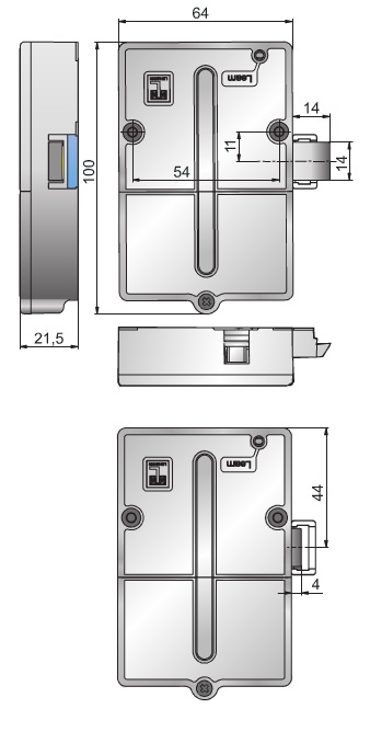
ELECTRONIC RFID-LOCKING-SYSTEM
The electronic RFID-locking-system IPLock Easy can be utilised for furniture made of wood and other non metallic materials which stands
out with its features and easy appliance. The cabinet lock is suitable for revolving or sliding doors as well as drawers, which can be locked invisibly.
The surface of the furniture will not show the lock, therefore the design will not be affected. The lock can be opened by different kinds of
transponders, like a card, a wrist band or a remote with or without combi code. The access control is possible for up to 50 users. The coding
is possible without the help of a computer.
Central locking system

The locking system in a vehicle must grant access only to authorised persons. It is the means via which the vehicle doors and boot lid are locked and unlocked and the engine is started.The locking system is...
Environmental protection
In the event of an accident, fuel filler caps with locks, which are also available for retrofitting, improve both safety and the protection of the environment by preventing fuel from escaping. Moreover, the valve systems installed in modern fuel filler caps reduce fuel evaporation. In the field of commercial vehicles too, locking systems make an active contribution to the protection of the environment, as they provide an assurance of safety for urea tanks. Urea is used to meet the strict environmental standards of Euro IV and V and to reduce the toxic emissions of diesel vehicles.
Function
The locking system in a vehicle must grant access only to authorised persons. It is the means via which the vehicle doors and boot lid are locked and unlocked and the engine is started.The locking system is operated with a key or remote control.
In years gone by, purely mechanical locking systems were the norm. Each door or lid had an independent mechanism which could be operated from the outside with a key or from the inside with a knob. Central locking systems, for which pneumatic drives were used originally, brought about significant improvements in comfort and convenience. These systems feature a built-in vacuum reservoir which triggers the locks on all doors when the key is turned in a lock.
Electric locking systems are commonplace in today's vehicles. Most of these combine a key with infrared or wireless remote control. This means that they can be triggered remotely, i.e. without contact between key and vehicle. Today, most vehicle manufacturers only fit a lock which can be operated with a key in one door, so the car can be unlocked in an emergency. The very latest systems enable entirely keyless vehicle access. Drivers only need to have the transmitter in their pockets, for example. The doors are then unlocked when the driver touches a door handle which has a built-in contact point.
The locking system comprises the following components:
Door handle/Handle strip
The door handle is the traditional means by which a vehicle is opened and closed from inside or outside. The external door strip usually houses the door lock. Door strips are increasingly used as design elements in modern cars. They can be chrome-plated or paint-finished in the same colour as the vehicle.
Door lock/Actuator
The latching mechanism in a vehicle is installed directly in its doors. It contains both a latch and an electric motor (actuator) which controls the central locking. The latch opens or closes the doors, whereas the door lock locks or unlocks the vehicle. Today, all door latches are powered by electric drives.
Fuel filler cap
The fuel filler cap must securely seal the fuel tank. Some fuel filler caps have locks, others do not. Fuel filler caps with locks are usually found on vehicles which have either a fuel filler flap which does not lock or no fuel filler flap at all. Fuel filler caps without locks are found on vehicles whose fuel filler flap is locked automatically via the central locking system.
Transponder
The transponder is usually integrated inside the key bow. It is the means by which the electronic immobiliser identifies that the correct key is being used. The transponder's code is read out as the key nears the ignition lock. If the code is correct, the electronic immobiliser sends the start enable to the engine.
Remote control
Remote controls are being used with increasing frequency in small cars, replacing the functions of a conventional key to all intents and purposes. A signal transmitter sends a signal or a coded order instruction to a receiver inside the vehicle, which usually controls a number of functions. Infrared remote controls have a range of up to 15 m. They rely on direct "visual" contact between transmitter and receiver. Today, infrared remote controls are only used rarely as they have been overtaken by other technologies. Wireless remote controls transmit on radio frequencies and have a range of up to approximately 100 m.
Keys
The basic function of keys and remote controls is the locking and unlocking of doors, luggage compartments, fuel filler caps, etc. they are also used to control the interior lighting and electronic immobiliser, the alarm system and the window lifters. The keys comprise two units: the milled, toothed key blade and the key bow. The latter is home to an increasing number of electronic functions such as the remote control for the central locking system or the boot lid.
Start/stop system
Traditionally, a vehicle key was needed to unlock the steering lock and to start the engine. Subsequently, the vehicle key was enhanced with the addition of a transponder-based release mechanism for the electronic immobiliser. Today, keyless systems are increasingly being used to start engines. In a keyless system, a transmitter – which usually also houses the controller for the central locking – is inserted into a reader in the vehicle and the engine is then started by pressing a button. A more recent development has seen the use of systems that work without any contact at all. Here, it is sufficient to simply "take along" the transmitter (carrying it in a trouser pocket, for example) and press the pedals before starting the engine by pressing a button.
Steering lock
Steering locks have been a mandatory requirement set by insurance companies since 1969. They provide protection against theft. They are the means by which the steering column is unlocked and the engine is started – either electrically or in by conventional mechanical means.
Safety
Modern locking systems help to increase both security and safety in vehicles. Where security is concerned, they provide protection against theft and, in conjunction with an alarm system, act as a deterrent. In terms of safety, the integrated control of lighting elements when doors are unlocked, for example, contributes to safety on the road by improving the visibility of open doors.
Locking systems

Locking systems are designed to open front and interior doors with or without electronic door release. Access can be granted either by numeric codes, transponders or also bio metrically with a finger print. For this reason, input and reader units, without any installation or overhaul efforts, are operated as small systems stand-alone or are integrated into door communication system as an extended function.
- Door release with three different technologies
- Transponder technology to release doors without electronic door release
- Application for door release or for alternative release functions
- Available as pre-fabricated small system
Three technologies enable the door release either by numeric codes, transponders or bio metrically with finger print. The function can be installed stand-alone or can also be integrated into front door stations and operated accordingly. In any case, a compact code lock can be installed at the front door but also in interior rooms being as slim as a switch. Access is granted by entering a numeric code and thus it is key-less. The core advantage is that numeric codes can be easily send out and used on site without having to present an identification badge such as transponder cards. A small system can also be equipped with a transponder reader and relevant transponder cards. The reader can either be installed surface-mount or be integrated into a knob cylinder, depending whether an electronic door release is available. In as such, interior doors can be equipped with knob cylinder-integrated transponder readers. Apart from door release by these three technologies also alternative trigger functions such as switching of light or operating a door drive.
Flexible installation and integration variants
The input and reader devices of a locking system can be separated and separately installed and thus they offer an easy to install solution which is suitable for retrofitting resp. Extensions of an existing communication system. When installing a new communication system the input and reader device can be directly integrated into front door stations.
The system can be modularly extended to the following functions:
- Access control
- Video surveillance
- Telephone linking
- LAN and WIFI as well as internet linking

Password based Digital Locking System

it is a password based digital locking system using a micro controller. It is another type of security structure that asks users to enter a predefined password before allowing access to protected appliances, doors or other systems. The circuit utilizes the dynamic series connectors from TE connectivity to provide a reliable and strong connection in between components.
The design is primarily comprised of a micro controller, an LCD interface, a matrix keypad and an electronic/electromechanical lock protected system. The dynamic series connectors provide connector solutions ranging from signal level circuitry up to power circuits. With the use of these connectors, disorganized wiring is avoided which makes circuit troubleshooting easy. In this password based digital locking system, the user is prompted to enter a password through the keypad, before allowing access. The entered password is sent to the micro controller. Then, the micro controller compares the entered password to the predefined password. If the passwords do not match, the red LED will glow and the LCD will display an error message. The user is required to press the reset button to enter a password again. If the passwords do match, the green LED will glow and the LCD will display a message "Successful Access". The micro controller will then send a logic signal to unlock the protected system.
The design is very useful disallowing unauthorized persons gain access to the users' equipment. The design is applicable, but not limited to doors, gates, turnstiles, cabinets and moneyboxes.

The circuit is a type electronic lock designed to work stand-alone. It uses iButton device that makes it a unique and durable type of access control. Unlike RF cards and other type of access control technology, the iButton is more versatile due to its size and concept of storing information. The iButton device can consider many complementary technologies, and the communication rate and product breadth of iButton devices go well beyond the simple memory products typically available with RFID.
The design is comprised of an 8-bit micro controller that manages the I/Os data. The ADM1232 device is a microprocessor supervisory circuit for the monitoring of the processor IC. The PCA24S08ADP device is an Electrically Erasable and Programmable Read-Only Memory (EEPROM) that stores an amount of data and saves when the power is removed. The LSHD-5601 device is a 7-segment common anode led display that produces the visual representation on the programming of additional keys. The IRF540 device is a power MOSFET that controls the solenoid. The NE202930-T1-A is an NPN epitaxial transistor that controls the IRF540 power MOSFET. The several types of diodes are used for protection and rectification. The power supply circuit is comprised of a standard power supply components with battery holder as an alternative supply of the system.
The design is comprised of an 8-bit micro controller that manages the I/Os data. The ADM1232 device is a microprocessor supervisory circuit for the monitoring of the processor IC. The PCA24S08ADP device is an Electrically Erasable and Programmable Read-Only Memory (EEPROM) that stores an amount of data and saves when the power is removed. The LSHD-5601 device is a 7-segment common anode led display that produces the visual representation on the programming of additional keys. The IRF540 device is a power MOSFET that controls the solenoid. The NE202930-T1-A is an NPN epitaxial transistor that controls the IRF540 power MOSFET. The several types of diodes are used for protection and rectification. The power supply circuit is comprised of a standard power supply components with battery holder as an alternative supply of the system.
Passive Keyless entry-Transponder

Passive Keyless Entry (PKE) transponder allows one to gain access by simply having a valid transponder in their possession. One prominent application of this schematic is in vehicle access wherein the person may be able to have an access to the vehicle without the need of pressing a button but only by having the valid transponder with them.
Hands-free PKE applications require bidirectional communication between the base station and transponder units. The base unit inside the vehicle transmits a Low-Frequency (LF) command that searches for a transponder in the field. Once located, the transponder in the vehicle owner’s possession then automatically responds to the base unit. The base unit then unlocks the car doors, if a valid authentication response is received. Typical PKE applications adhere to the electromagnetic field radiation rules that are mandated by the government agencies in relation to the maximum power transmitted by the transponder and base station.
The PIC16F639 has a digital MCU section (PIC16F639 core) and an analog front-end (AFE) section. The device can be used for various low-frequency sensing and bidirectional smart communication applications. The base station unit transmits a 125 kHz command to search for a valid transponder in the field. The PKE transponder sends back a response if the received command is valid. The PIC16F639 device has high analog input sensitivity (up to 1mVPP) and three antenna connection pins. By connecting three antennas that are positioned to x, y and z directions, the transponder can pick up signals from any direction at any given time.

This system is capable of handling high density access control which is common to train stations and industrial manufacturing. The circuitry uses 2x16 LCDs as the direct monitor of the system and 20x100 LCD for the main display. The system is programmable for other purposes and usages as well.
It is comprised of microcontrollers that handle data and operation of the subsystems. The 80C51 microcontroller has 128x8 RAM and 4000x8 ROM which is ideal for access control system application. The design is static, therefore the clock can be stopped without loss of user data and the execution can be resumed from the point the clock was stopped. The CLRC632 reader IC supports all MIFARE products and protocols. It is a small but fully integrated package as a reader IC for contact less communication. The PCA8539 LCD driver is also excellent for high-contrast Vertical Alignment (VA) LCD with multiplex rates up to 1:18 ratio and generates drive signals up to 1,800 elements.
It can also monitor an individual's interaction with their appropriate information. Aside from people, it is also appropriate for product inventory and other information management applications. It can handle a wide range of methods and protocols for contact less communications and can operate at high data rates. The design itself is so versatile that it could be developed for wide range of applications.

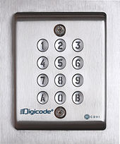


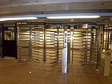


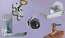

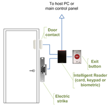

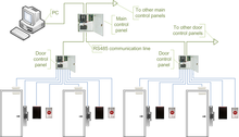

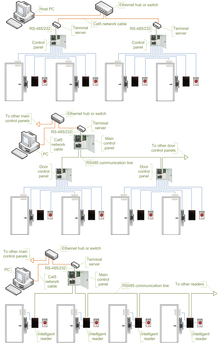

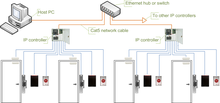

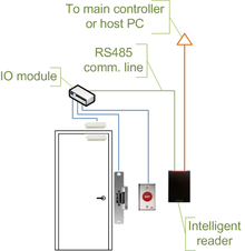

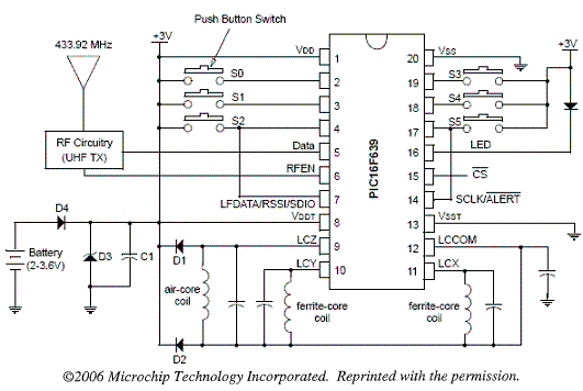




 Pictures showing the flippers' angle due to the action of the autopilot system, during one of the sea trials. (a) the robot is performing a heave-up maneuver to maintain depth and attitude at zero forward speed. (b) the robot is executing a combined heave up, pitch up and slow forward speed maneuver. (c) the robot is performing a pitch-up maneuver at high


