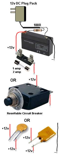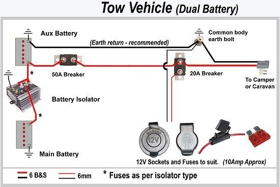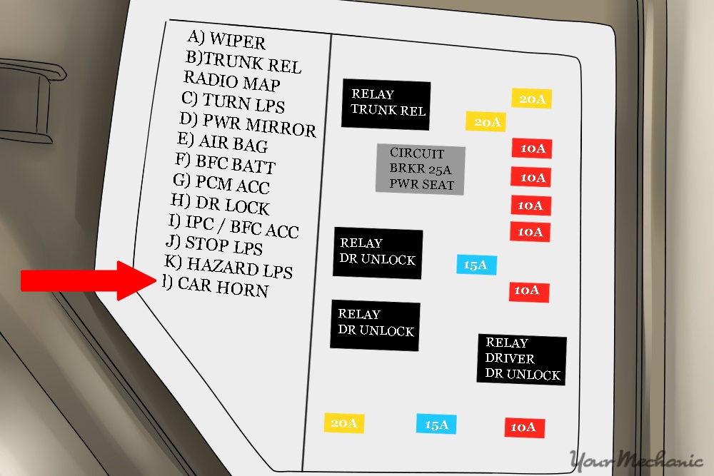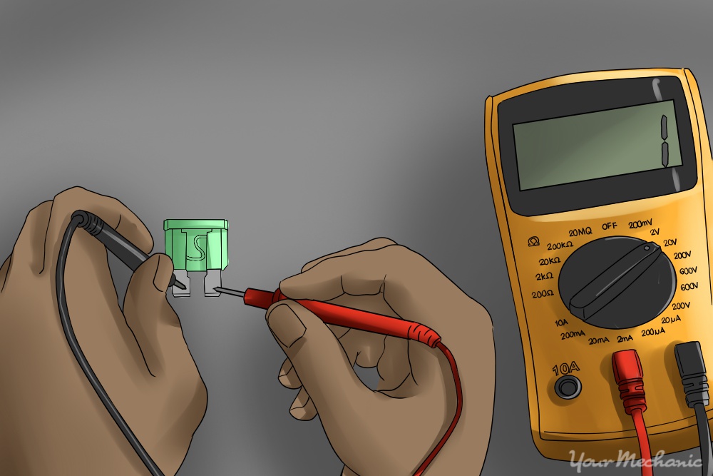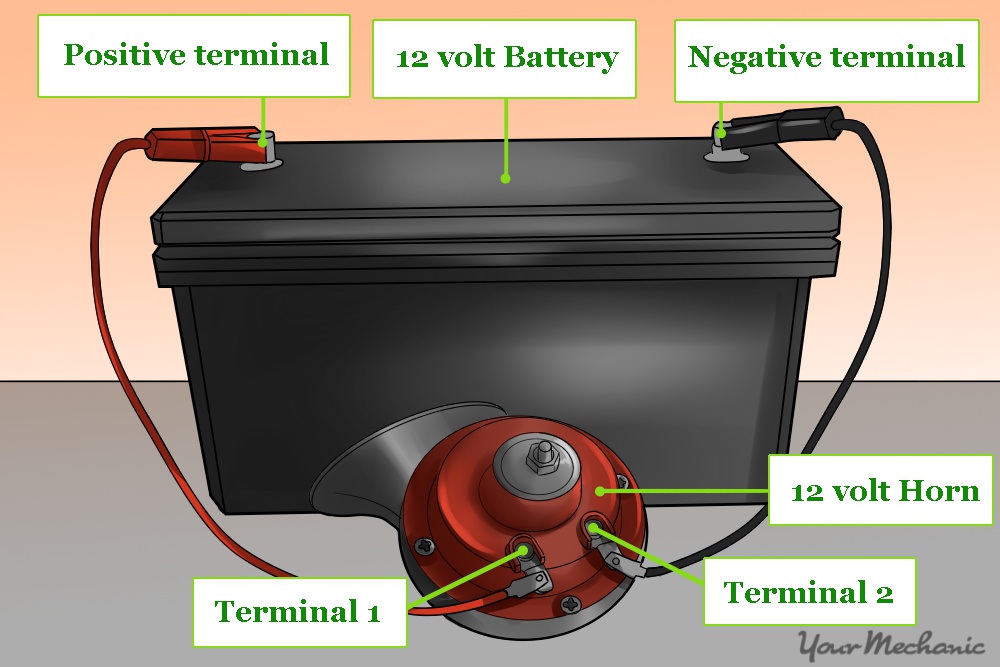
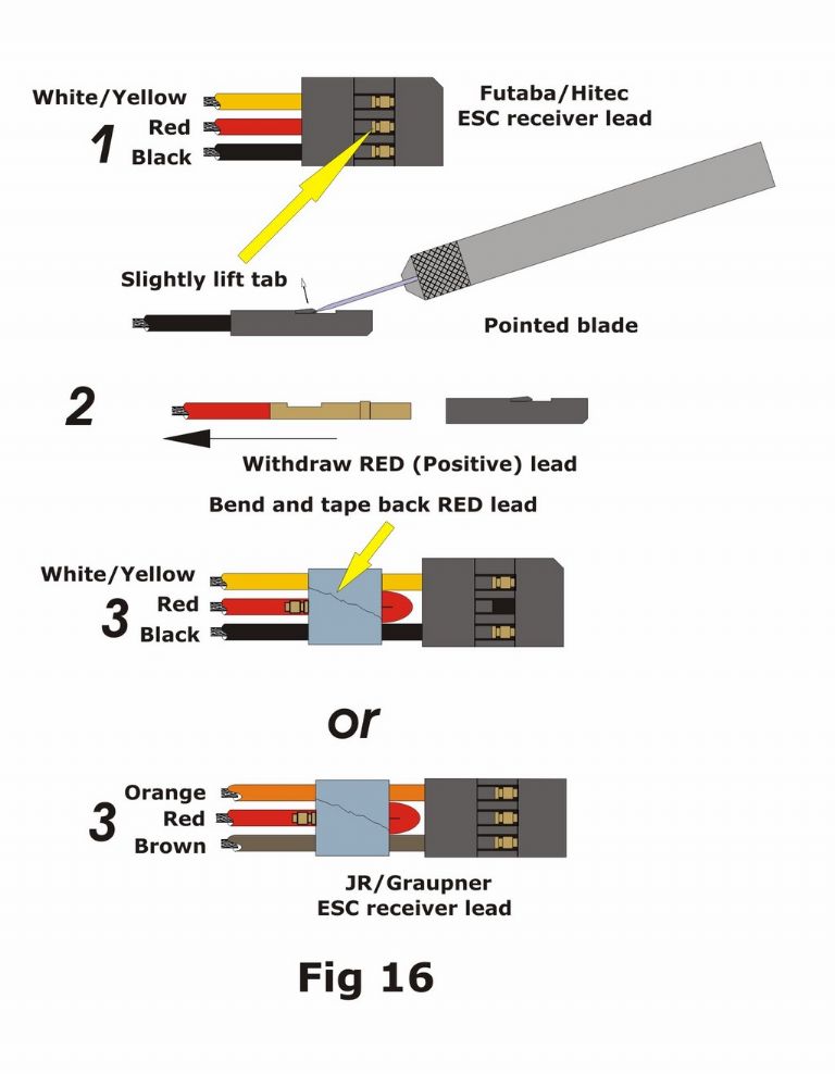
The purpose of a fuse is primarily safety. A fuse probably won’t stop a stalled motor from blowing the output FET's in a speed controller, but it will blow fast enough to stop cables and contacts from overheating and catching fire. Choose a value which is just a little above that at which you get nuisance blowing of the fuse, e.g. try a 5A fuse in circuit with a 10A ESC (electronic speed controller) and if it continually blows when the motor is at full load, replace it with a 7.5A one or even higher rating if required, but don’t exceed the maximum rating of the ESC with the fuse value. For those who want to know whether to fit a fuse between the battery and ESC or between the ESC and the motor, there’s no harm in doing both, but you must ALWAYS fit one in the positive line between the battery and the ESC somewhere. This is also the place for the main On/Off power switch.
For fuse values of less than about 2A you can use those clear glass cartridge fuses fitted to an in-line, spring–loaded holder. These aren’t very useful for higher currents, as the contact area at each end of the fuse is very small which can produce excess heat and melt the holder. I favour the automotive ‘blade fuses’ which go up to 30A, are widely obtainable, and are not expensive. You can even buy a fuse holder for these with an indicator diode which glows either red or green depending on which way the current is flowing, which is very useful for setting motors up
XXX . X Evolution of Pixels: From Lamps to SMD LEDs
Much has been written about LED screens. During 20 years of their history, screens changed significantly. We decided to devote this article to the evolution of the key element in a digital screen, to the pixel.
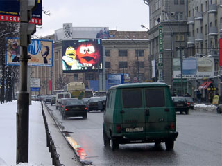 12x9 m lamp screen in Moscow, 2001
Working conditions on digital screens are the most unfavourable for lamps: a constant “on-off” mode. To extend the life of lamps a simple method was invented: to reduce the feeding voltage. Lamps now worked longer but another problem surfaced: with lower power the visible spectrum shifted into the red zone. One monochrome screens this could be easily disregarded but created grave problems for multicolor and full-color screens.
To turn a lamp screen into a multicolor installation was fairly easy: standard white lamps were either painted into red, green, blue and light-blue or placed behind color filters. Light filters absorbed a large part of light radiation and to keep the screen brightness it was necessary to place a reflector behind the lamp. The quality of colors, white balance and brightness of the screen fully depended on the quality of lightfilters and reflectors, their precise positioning. Naturally, such systems were complex in manufacturing and assembly, bulky and expensive.
Another serious shortcoming of incandescent lamps was their high power consumption. For example, typical screens with three inch pitch (76.2 mm) used lamps for auto industry 1250X (Uwork=13.5V, Icons=0.37А, lifespan 500 hours). One pixel contained 4 such lamps.
At 12V voltage one pixel consumed 16W, and one square meter of such screen consumed nearly 3kW of energy. Thus, a relatively small screen with 112x84 pixels and image area of 54.5 square meters turned into a powerful energy plant with maximum power consumption (white peak) of 165kW.
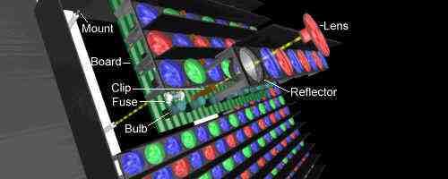
Lamp screen module
In spite of high energy consumption, the total brightness on lamp screens was insufficient for daytime operation, about 2500 nits. To increase brightness by placing lamps closer together was impractical: any increase in resolution lead to increase in power consumption and significant problems with heat dissipation.
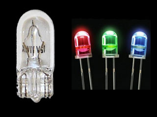 Automotive light bulb 1250X and LEDs
Bulb size 10.2х26.9 мм
Screen manufacturers were interested in LEDs as potential replacement of incandescent lamps. Initially, they started experimenting with monochrome or two-color displays by combining red and green LEDs. New light emitting elements allowed to significantly reduce power consumption, increase brightness and reliability.
First LED screens were created as a simple replacement of lamp screens. Structurally they were based on clusters widely used in information signs. A cluster is a unit that includes LEDs (in various combinations), frame (box) and connecting cables. This structure is convenient in maintenance and allows easy replacement of a failed cluster. Though manufacturers guaranteed long life of individual LEDs (50 000 hours, sometimes even 100 000 hours) in reality few manufacturers reached such excellent parameters. Among those few are Nichia, Toyoda Gosei, HP/Agilent, Cotco/Cree. Clusters were an intermediate stage, some other technological solution was needed.
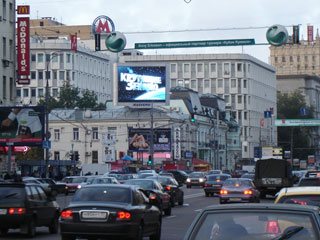 Outdoor LED screen 8х6 m, 22 mm pitch in Moscow, 2006
First LED screens have relatively low resolution. Typical lamp pixels of 76.1 mm (3 inches) were replaced by LED pixel of 38.1 mm (1.5 inches). To maintain or even to increase the brightness (while maintaining the white balance) of the image area it was necessary to arrange a cluster of several LEDs, for instance, 4 red, 4 green, 2 blue. This pixel consumed about 1W, or 16 times less energy than a similar lamp pixel. Thus, a screen with 2 times higher resolution would provide a much better image and has 4 times lower power consumption. More actually, since ventilation system was no longer required.
Though a step ahead compared to lamp screens, LED screens based on clusters had some serious shortcomings: too many connectors reduced reliability of the system, large number of small components resulted in increased cost and longer assembly time.
The task of increased reliability and lower cost was solved by placing large number of LEDs in one module (64, 128, 256 and other options). Any failed component on a module (LED, passive component, or driver) required replacement of a whole module. This was especially true in relation to outdoor screens: modules had to be protected against rain and snow by compound that hermetically sealed the PCB.
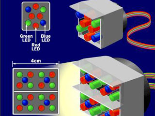 | |
| 4R2G2B and 2R2G1B LED clusters | LED screen with 2R2G1B pixels |
The use of LEDs allowed to move away from a 12V systems (lamp screens) to 5V. This change also led to lower power consumption and better heat dissipation. 2RGB or RGB pixel consumed approximately 0.3W, the whole square meter of a screen based on a popular 19 mm pixel pitch consumed 839 W at the peak of white. A 6x4 meter screen with 320х240 resolution consumed only 20kW (a drastic reduction compared to lamp screens).
As the pixel grow physically smaller, it became smarter: developers of LED screens started using various brightness and resolution enhancement techniques. Our magazine published articles about virtual or dynamic pixel repeatedly: “Virtual pixel: Promotional trick or image improvement”.
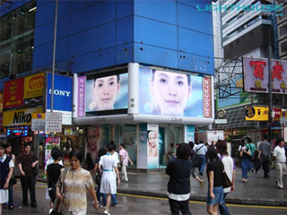 Two outdoor LED screens with 6 mm pitch in Hong Kong
Photo credit: Lighthouse Technologies
All future hope to change LED pixel were concentrated on an SMD LED (surface-mounted). Once invented SMD LEDs were meant for indoor applications only, because humidity negatively affects their operation.
Different SMD LEDs were tested: single color LEDs, large and small sized LEDs. But the most promising option of 3-in-1 SMD LEDs became most popular. At present, the physical size of an SMD LED is limited by technological processes of surface-mounting machines to 4 mm.
One of the main shortcomings of SMD LEDs was bad contrast. Fully switched off SMD screen looks whitish because of the white background for LED chips. The efforts of developers were focused on solving the contrast problem – and finally the solution appeared in the market in the form of so called black face SMD.
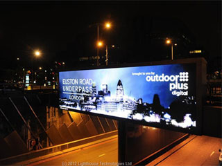 | 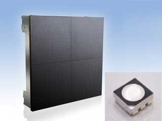 |
| Modern outdoor 12 mm pitch LED screen in London: 12.3x3.5 m Photo credit: Lighthouse Technologies | Black face SMD LED module Photo credit: Ekta |
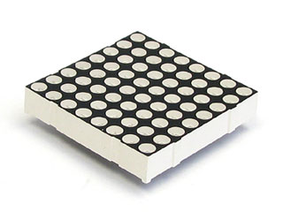 LED module based on Dot Matrix technology
Comparative tables of power consumption in the evolving pixel
| 4 Lamps Pixel | DIP LED cluster | DIP LED pixel | DIP LED pixel | SMD LED 3-in-1 | |
|---|---|---|---|---|---|
| RGBbrB | 4R4G2B | 2RGB | RGB | RGB | RGB |
| 1:1 | 1:4 | ||||
| 16W | 1W | 0.4W | 0.3W | 0.3W | 0.075W |
As we see, in less than 20 years pixel changed and modified significantly. Obviously, this is not the end of the road; probably, only the beginning of the pixel story. But whatever the case, we have to know this story well.
40 RGB LED Pixel Matrix
What exactly is an LED screen?
An LED Screen is like a giant television, but with one fundamental difference: instead of the picture being beamed from a cathode ray tube, each pixel is made up of a cluster of tiny LEDs (like the one's you find in modern bike lights, but brighter).
Each cluster on an LED screen has a red, green and blue LED, which light up accordingly to create the correct colour. If you look very closely at your television set then you can see individual pixels. If you look very closely at an LED screen, all you see is lots of very bright little lights, because the pixels are much bigger, but when you get further away the picture becomes clearer.
Back to questions
So it's not an LCD screen then?
No, LCD screens are much smaller and use a different technology. Unlike the clusters of LEDs that make up an LED screen, a picture on a LCD screen is produced by electrically ‘relaxing' twisted liquid crystal molecules and passing light through them from a backlight. A completely relaxed molecule will become almost completely opaque, while a fully twisted one will allow the full luminosity of the backlight through, and this method creates the picture which is shown on the screen.However, if you would like LCD screens or plasma screens, we also offer them for both rental and sale. Many of our customers require LED screens for their main event and plasma screens to show it in corporate areas.
Back to questions
What about LED TVs – are these the same as LED screens?
LED TV is a very misleading name for these consumer products, and one that complicates people's understanding of LED screens even more! In short, an LED TV is not an LED screen and using completely different technology to LED screens.The so-called LED TV is fundamentally exactly the same as a normal LCD television. However, instead of using a fluorescent tube to backlight the screen, it uses individual LEDs. A more accurate name for LED TVs would be LED backlit TV.
Back to questions
Why use LED screens instead of LCD screens?
The two technologies are used for hugely different applications – although these so called LED televisions are being released for home use, LCD screens are for use in indoor environments, typically for close viewing and for use as either televisions or computer monitors, while LED screens are more suited to large screens and for making an impactThe key reasons for this are:
- Brightness – We've all seen what an LCD screen or CRT television looks like when the sun shines on it – you can't see the picture. LED screens use incredibly bright LEDs, designed specifically to be visible in bright sunlight. This is the key strength of LED screens; LCD screens simply are not usable in an outdoor environment and even indoors they don't have the same impact. The same goes for projectors – these are only effective in low light conditions; fine if it's a dark night, but not much good during the day!
- Strength – LED screens are made up of individual panels which are put together seamlessly. Imagine if you were to do that with LCD screens? Besides having borders around each panel, they are very fragile and easily cracked if moved around a lot, and once this happens the LCD screen is useless. LED screens are far more robust and easy to service – should an LED be broken it is easily replaced – making them far more usable as well as cost effective.
- Impact – If you want your message to stand out, then LED screens are the way to go, as they are bigger and brighter with much richer colours.
How about Projection Screens?
Again, these are different types of giant screen. Projection screens are like a cinema – they are a sheet that you project an image onto. They come in ranges of sizes, although – unlike LED screens – they are not at all effective in daylight and are generally for indoor use only. Because of their lower brightness, they also do not tend to make such a dramatic impact as LED screens. Again, at ADI we also offer projection screens if you so require.Back to questions
I've heard of a Jumbotron – is this an LED screen?
LED screens go under a number of monikers and there are many brand-names, of which Jumbotron is one (used by Sony). Other examples of LED screen brand-names are: Megascreen, Lighthouse R7, Barco, D-Lite, Starvision, Monsterscreen and Optiscreen. People also refer to LED screens as giant screens, big screens, concert screens, big tvs… you get the picture!Back to questions
What are SMD LED Screens?

SMD LED screens use tiny (the size of a pin head) red, blue and green diodes, set very close together in a single package measuring only a few millimetres across.
SMD screens have much shorter viewing distances than discreet screens and because of their compact package size can be made with much higher resolutions.
Back to questions
I've heard people talk about ‘pixel pitch' with LED screens. What does that mean?
On LED screens, the pixel pitch is the distance between each cluster of LEDs that makes up a pixel and is measured in millimetres. It ranges from around 3mm for indoor LED screens for very close-up viewing, to around 30mm for outdoor LED screens to be viewed from a distance.Pixel pitch is important when you choose an LED screen, but a smaller pixel pitch doesn't always make sense and can cost far more – it all depends on the distance the screen is being viewed from. Pixel pitch is only a small factor from many that determine the quality of a giant screen, so don't be sold on that alone!
Back to questions
What About ‘Virtual Pixel Pitch'?
On many LED screens, a technique known as ‘virtual pixel pitch' is used which shares LEDs between pixels, thus making the giant screen appear to be a higher resolution. So when someone talks about a ‘virtual pixel pitch' of 10mm, the screen is likely to actually have a 20mm pitch, but use virtual pixel technology.It's important to be aware that a virtual pixel pitch does not make a huge amount of different. For instance, a 10mm ‘virtual' screen will never look nearly as good as an ‘actual' 10mm screen, so it is always best to go for the smallest ‘actual' pixel pitch that you can afford.
What does an LED screen cost?
We offer LED screens not only for sale, but also LED screen hire. Costs of LED screens have lowered significantly in recent years, as the technology has advanced and all ADI Virtuality LED screens are available in either E, S or P specification to suit all budgets and requirements.XXX . XV0 What is Pixel Pitch and Resolution


Furthermore, the high-energy blue light could be used to excite phosphorus and directly produce white light - the basis of the next generation of light bulb.
Today, blue LEDs are found in people's pockets around the world, inside the lights and screens of smartphones.
White LED lamps, meanwhile, deliver light to many offices and households. They use much less energy than both incandescent and fluorescent lamps.
That improvement arises because LEDs convert electricity directly into photons of light, instead of the wasteful mixture of heat and light generated inside traditional, incandescent bulbs. Those bulbs use current to heat a wire filament until it glows, while the gas discharge inside fluorescent lamps also produces both heat and light.
Inside an LED, current is applied to a sandwich of semiconductor materials, which emit a particular wavelength of light depending on the chemical make-up of those materials.
Gallium nitride was the key ingredient used by the Nobel laureates in their ground-breaking blue LEDs. Growing big enough crystals of this compound was the stumbling block that stopped many other researchers - but Profs Akasaki and Amano, working at Nagoya University in Japan, managed to grow them in 1986 on a specially-designed scaffold made partly from sapphire.
Four years later Prof Nakamura made a similar breakthrough, while he was working at the chemical company Nichia. Instead of a special substrate, he used a clever manipulation of temperature to boost the growth of the all-important crystals.
HDR Cinema Projector Works—Probably

A high dynamic-range projector from Christie and Dolby promises something special in commercial cinemas, but how does it work?
Last December, I posted an item about Dolby's announcement that 2015 would see the inauguration of Dolby Cinema, a bold plan to take commercial cinema to the next level with Dolby Atmos immersive sound and Dolby Vision high dynamic-range (HDR) laser-illuminated projectors co-developed with Christie. One of the first public showings of this projection technology was presented last week at CinemaCon, the convention of the National Association of Theatre Owners.
Ever since I first heard about these HDR cinema projectors, I've been very curious about how they manage to achieve high dynamic range. I've asked several people from Christie and Dolby to explain it, but they have all declined. Fortunately, AVS member CinemaAndy pointed me to the patent application submitted by Christie for an HDR projection system, which must be the basis of Dolby Vision in commercial cinemas. And since that information is in the public domain, I can share it with the AVS community.
The patent application starts with a description of current digital-projector technology, which is illustrated in the following diagram:

A conventional digital projector sends white light from a lamp (1) through a lens (2), which reflects from a mirror (7), travels through a transparent integrator rod (5), reflects from another mirror (7), passes through more lenses (6), reflects from another mirror (7), passes through yet more lenses (6), and ends up in the imaging engine (8), where it is split into red, green, and blue components. Each component illuminates a corresponding spatial modulator or "imager" that forms the image for that color in an array of pixels, after which the red, green, and blue light is recombined and projected through the main lens (9) to the screen. The imagers can be DLP DMDs (Digital Micromirror Devices), LCD panels, or LCoS panels. And the white-light lamp can be replaced with red, green, and blue lasers that illuminate the corresponding imagers directly or a hybrid design with blue lasers and a yellow phosphor wheel whose light is split into red and green.
According to the patent application, the dynamic range of a digital projection system is determined by the capabilities of the imager. In the case of 4K DMDs, the application claims the dynamic range is roughly 12 bits at 24 frames per second, and less at higher rates.
The architecture of the proposed HDR projector is much the same, with two critical differences—another spatial modulator and an added array of integrator rods:

In the proposed HDR architecture, the mirror in the upper left of the previous diagram is replaced with another spatial modulator (15) that is divided into an arbitrary number of zones. Each zone is controlled to send more or less light through an array of integrator rods (16), depending on the brightness of the final image in each zone. In the case of an RGB laser-illuminated projector, each laser would have its own integrator rod (5), zonal modulator (15), and array of integrator rods (16) as well as its own imaging modulator that creates the final image for that color.
For those who might not be familiar with an optical integrator rod, it's a transparent rod whose surface is internally reflective—that is, when light enters one end, it is reflected multiple times by the internal surface of the rod. This "homogenizes" the light, converting round or irregular patterns of illumination into a uniform, rectangular pattern. The cross-sectional shape of the integrator rod is typically the same aspect ratio as that of the imagers.

In this conceptual example, the zonal modulator (15) is divided into only four zones (20a-d); in practice, there would be many more zones. In the case of a DMD, the micromirrors in each zone are oriented in a pattern that reflects more or less light, depending on the brightness of that part of the final image. Virtually no light is reflected when all the mirrors in a zone are in their "off" position, while the maximum amount of light is reflected when all mirrors are in their "on" position (20b), and half that amount of light is reflected when the mirrors are in a checkerboard pattern (20d). A complete grayscale is generated by orienting the mirrors so more or less light is reflected from a given zone; for example, zone 20a in this diagram reflects less than half the maximum amount of light, and zone 20c reflects more than half the maximum light.
Interestingly, the mirrors in each zone are held statically in their positions during each entire frame of the video. Why not create a grayscale by alternating all the micromirrors in each zone between on and off many times per frame as an imaging DMD does, varying the percentage of time they spend in the on and off positions (a technique called pulse-width modulation)? Because it is exceedingly difficult to control the PWM frequency so that it's exactly identical for the zonal and imaging modulators, and any difference can result in visible artifacts. Instead, the mirrors in each zone are oriented in a spatial dithering pattern that reflects the desired amount of light as uniformly as possible.
Even so, the light from each zone must be highly uniform, so it is sent through another optical integrator rod. In fact, each zone has its own integrator rod and these rods are arranged in an array that corresponds to the array of zones.

In this diagram from the patent application, light from a laser (1) enters the first integration rod (5) and hits the zonal modulator (15), which reflects the light into an array of integrator rods (16; each rod is labeled 18 in this diagram). The light from the integrator-rod array passes through a single, hollow integrator (19) to blur the seams between the individual rods in the array. The light then hits the imaging modulator (13) at a non-right angle, causing keystone distortion, which can be compensated for with well-known optical techniques and/or image-processing algorithms.
This approach seems very similar to full-array LED backlighting with local dimming in LCD flat-panel TVs, in which the LEDs behind the LCD panel are divided into a number of zones that are dimmed and brightened according to the overall brightness of the image in each zone. This works well to increase the apparent contrast of the image, but it's not without problems of its own, such as halos around very small bright objects on a dark background within a single zone. Obviously, the more zones there are, the less haloing there will be, so I hope the Christie/Dolby Vision projectors have lots of zones.
The patent application does not specify the number of zones, nor does it specify exactly how much the dynamic range is increased over that of conventional digital-cinema projectors, other than to day say it's increased by several orders of magnitude. The basic technology achieves this by lowering the overall black level—which is annoyingly high in most commercial cinemas—and possibly increasing the peak brightness by cranking up the lasers.
When I sent this article to the two companies for fact check, the response was, "Dolby and Christie do not issue public comments about patent applications." So I can't be 100% certain that this is, in fact, the basis of Dolby Vision projection. But it seems a good bet for now.
As I mentioned, Dolby Vision was presented at CinemaCon, where the audience got to see the upcoming Disney-Pixar animated movie Inside Out in addition to several trailers, all graded for Dolby Vision high dynamic range. I deeply regret missing that presentation, which was spectacular by all accounts I've heard, and I look forward to seeing the first Dolby Vision movie, Tomorrowland, when it opens next month. The five locations in the US that are scheduled to be showing the movie in Dolby Vision—and Dolby Atmos sound—are the El Capitan in Hollywood, CA; AMC Burbank 16 in Burbank, CA; AMC BarryWoods 24 in Kansas City, MO; AMC Deerbrook 24 in Houston, TX; and AMC North Point 12 in Atlanta, GA.
By adding more diodes we can pass both the positive and negative portions of the secondary to our circuit and get a waveforms as shown in the diagram below. This waveform cannot be used in any electronic equipment as it will produce a lot of background "hum." In the next frame we will show how to improve the waveform. The 4 diodes in the rectifier are called a BRIDGE. The animation below shows how two diodes pass the positive waveform to the output and then the other two diodes pass the negative portion of the waveform. We have removed the two diodes that are not active during each portion of the cycle to show how the other two diodes work.
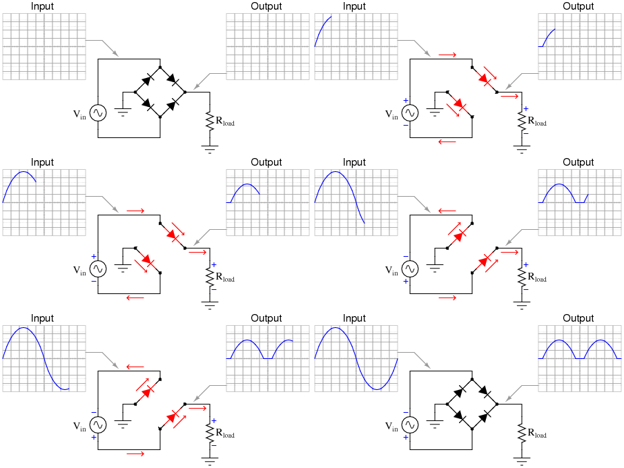
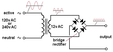
Fig 9. FULL-WAVE RECTIFICATION
From the previous frames you can see a circuit can perform differently by merely changing one or two connections or adding one or two components. That's why it is important to make sure the operation of the circuit is clear and is laid out in a way that can be easily recognised.
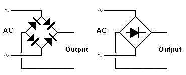 By drawing all the diodes in one direction, they can be replaced with a single diode in a diamond. Here are three layouts that will take a few minutes to work out:
Normally a circuit is drawn so it is easy to see what is happening. But sometimes a re-arrangement can be helpful.
The normal way to show the output of a centre-tapped secondary is Fig A. But re-arranging it to Fig B shows the diodes can be heatsinked on the earth-plane (chassis).
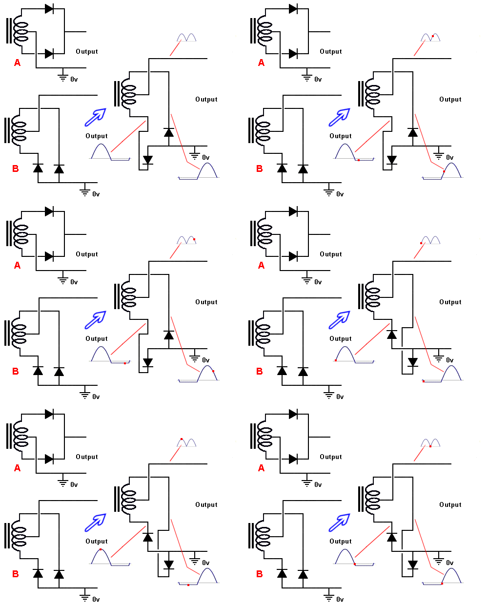
The animation of circuit B show the first diode gets "flipped over" as soon as the bottom winding of the transformer becomes negative and this puts the diode in "forward bias" where it starts to conduct and a maximum of 0.6v develops across it. This prevents the bottom winding moving any further and the centre-tap and top output increase in voltage. Note the voltage of the top winding is double the voltage on the centre-tap. But the voltage on the top winding simply goes to the other diode and nothing happens (the diode is put into "reverse-bias bias" mode and the voltage "sits" on the cathode and does nothing). This gives the centre tap an output to deliver current to the next section of the circuit (possibly a filter section).
Exactly the same thing happens with the other portion of the waveform.
There is a lot to understand in this animation. The output "pushes" against one of the diodes that is forward biased and thus it will drop 0.6v and create a "rigid point" for the waveform to push out the other winding and into a filter section. At the same time the other winding is supplying twice the voltage to the unused diode and nothing further is happening as the diode is reverse biased.
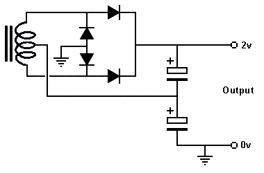 | It will take a minute to work out if the circuit on the left is a voltage doubler or a full-wave supply: (It's a voltage-doubler via two half-wave supplies. Two of the diodes are not needed, as explained above.) |
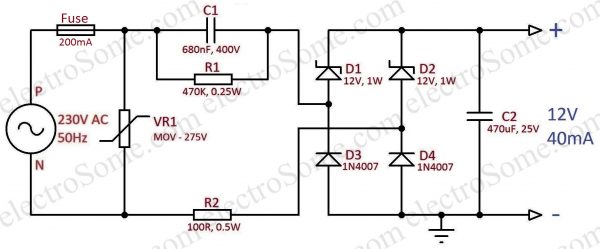
BEFORE THE ADAPTOR TAKING WE MUST A GIVE fuse
THE FUSE A fuse is simply a thin piece of wire.
But it can be designed to act quickly or slowly.
A "quick fuse" is called FAST ACTING and a "slow fuse" is called a DELAY FUSE.
A FAST ACTING fuse is also called a NORMAL FUSE.
It takes a lot of skill and knowledge to fit the correct fuse and also replace a fuse with the correct type.
A fuse doesn't really protect anything.
If a circuit gets overloaded, the fuse generally remains intact until one or more of the components "blows up" and the higher current heats the wire in the fuse and it melts.
The most common fuse in electronic work is 1 amp, 2 amp and 3 amp.
The rating "1 amp" is called the RATED CURRENT and is the current the fuse will handle for many years.
The term "FUSING CURRENT" is the value of current that will cause the fuse to melt. The time will depend on the construction of the fuse.
A normal fuse will allow about twice the rated current to flow and during this time the fuse can actually start to glow. This will oxidise the tin coating and the wire will gradually start to deteriorate. This will allow the fuse to fail at any time.
A DELAY FUSE is made with a piece of wire from one end and another from the other end and the two are soldered in the middle with a dot of solder.
If the two wires start to get hot, the solder melts and the wires separate.
This can happen at currents as low as 1.5 amp.
With fuses below 500mA, the wire is very thin and the current can gradually damage the coating and eventually it will fall apart for no reason.
As you can see, the fuse does not fail until at least 50% overload occurs and most transformers are not designed for this amount of overload.
Thus the transformer will fail and that's why some products have a 500mA fuse on the primary.
By the time the fuse fails, the transformer is "cooked."
The alternative to a fuse is a POLY SWITCH. This is covered in the next section.
Alternatively, a low value resistor can be used.
Sometimes a resistor is a good solution because, as the current increases to say twice the operating current, the power (heat) dissipated by the resistor will increase 4 TIMES.
This will damage any normal resistor.
PICO FUSES
PICO Industries developed a number of very small fuses with ratings from 100mA to 5 amp in a thin glass tube and having wires out each end so the fuse can be soldered to the PC board.
These small fuse became to be know as PICO FUSES and they are simply a "wire-in" fuse, contained in a very small glass tube.
Sometimes they are dipped and sealed.
Some of these fuses are hard to identify and difficult to determine the current rating.
You will need a multimeter to detect if the wire is intact. If is damaged, you will need to pull it apart and use a digital caliper to measure the diameter of the wire.
You will then need some new ones to pull apart and measure the diameter of the wire.
If there is a little spring inside the glass tube or a dob of solder, the fuse is a "SLOW-BLO" (DELAY) and it must be replaced with the same type.
A 1-amp "slow-blo" fuse will accept up to 3 amp for short periods of time and not get weakened because the wire is thicker than a normal 1 amp fuse. It works on the principle of the wire getting hot when 1.5 amps flows and the low-temperature solder melting.
When a power supply is turned ON, the electrolytics are uncharged and a very high current flow initially to charge them.
Both types of fuses will heat up during this time and you will be able to see the wire "sag" and then tighten again.
This process will gradually damage a normal fuse, whereas a delay fuse will not be affected.
There are hundreds of different types and styles of fuses for automotive, household, appliance and industrial protection.
If a fuse keeps blowing for no apparent reason, the first thing to do is refit the fuse up to 5 times and then use a delay fuse.
You cannot go to the next value as it will be 30% to 50% higher rating and the fuse you are already using is allowing up to 50% higher current to flow, before it fails.
If you fit a "stronger" fuse, the power supply may not be able to deliver sufficient current to activate the fuse and the equipment will "sit and burn" if a short-circuit develops.
Fuses in amplifiers are the hardest to replace because the amplifier takes a varying amount of current, according to the loudness of the music.
These fuses are generally "slow-blo" (delay) and the output wattage can be up to 10 times more than the average current when "loud thumping" is produced.
That's why you need to go by the manufacturers recommendation, as they have tested to equipment and come up with a value that does not prematurely fail.
This just a discussion to make you aware of the two different types of fuse and the approx current they are capable of handling.
AC FUSESThe current rating marked on the side of a fuse is DC CURRENT in AMPS.
There is no such thing as an "AC Fuse."
All fuses can be used in AC circuits.
In an AC circuit, the current will be say 1 amp for part of the cycle and less than 1-amp for the remainder of the cycle.
The heating effect on the wire inside the fuse will be exactly the same as a DC current of 1 amp.
This applies to all household fuses. A 10 amp fuse will allow 10 amps to flow and not be damaged or deteriorate. But what really happens is 14 amps will flow during the peak of the wave and less than 10 amps for the remainder of the cycle. The 14 amps is not present for long enough to overload the fuse.
Household fuses consisting of a length of wire are called "normal fuses."
A circuit breaker is called a FAST ACTING device and can be as fast a ONE CYCLE.
It detects excess current by producing magnetic flux from two turns of wire made from the conductor carrying the current. This magnetic flux is detected by a Hall device and a relay is activated to open the circuit. This is a totally different principle to a "hot wire" fuse.
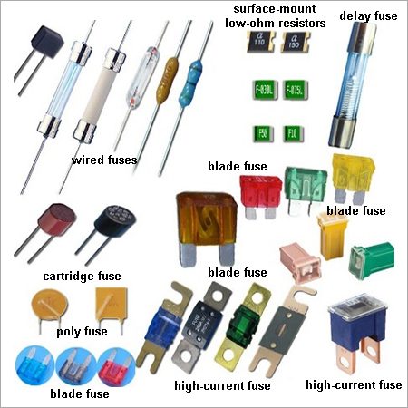
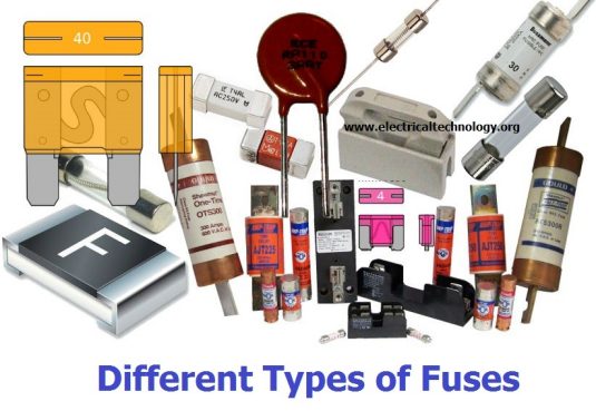
DIFFERENT TYPES OF FUSES
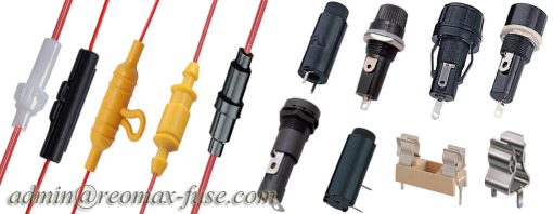
These images show 5 in-line fuse holders,
then panel-mount fuse holders and fuse clips at the bottom
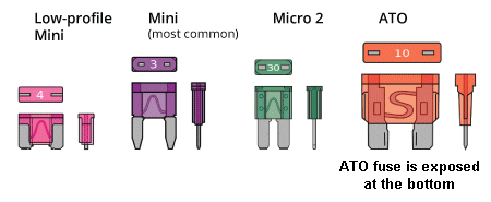
These images show blade fuses
Low-ohm surface-mount resistors can be used as a fuse because the current flowing through the resistor will create heat. The amount of heat is a product (multiplication) of the current flowing and the value of resistance. Basically you can say the wattage dissipated is four times greater when the current doubles. That's why it heats up and fails.
But there is a voltage drop across the resistor AT ALL TIMES and you must take this voltage drop into account when designing the project.
There is no voltage drop across a "normal" (wire) fuse.
But there is a voltage drop across the resistor AT ALL TIMES and you must take this voltage drop into account when designing the project.
There is no voltage drop across a "normal" (wire) fuse.
POLY SWITCH
Designing and testing circuits up to 1 amp has very few problems.
Most parts carrying 1 amp do not get very hot and the wiring can be light duty cable.
When the current is greater than 2 amp, you need to take additional precautions because the power supply you are using will deliver a high current and there is a high current flowing most of the time.
If you are using a power supply with current-limiting, use this feature, but if you are using a 12v battery, up to 100 amp can flow if a short-circuit is created. This will burn the leads and even the tracks on a PC board.
I am very careful whenever I use a 12v battery because two wires touching will burn out all the wiring.
There is a simple way to protect everything. It is called a FUSE.
It is the cheapest and best item.
You can use a 1amp, 2 amp or 3.15amp fuses
You can also use a circuit breaker.
You can find a 10 amp circuit breaker in a damaged power board. Just pull the power board apart and re-use the circuit breaker.
Finally you can use a POLY SWITCH.
This is a crystalline structure that has a very low resistance (something like 0.05 ohms). When a current flows through the structure it gets slightly warm. When a higher current flows, it gets slightly warmer and its resistance increases.
This causes more heat to be produced (by the structure) and it gets hotter and hotter. Within a very short period of time its resistance is very high and only a very small current flows.
This current is called "Leakage Current" and can be from 20mA to 100mA.
The voltage of the supply and the leakage current will create heat in the device to keep it in a state of high resistance.
A Poly Switch can take from 10mS to 10 seconds to activate (respond) and this depends on the voltage of the supply and the short-circuit current (the voltage of the supply has an effect on the maximum current flowing).
You need to remove the supply and wait a few seconds for the Poly Switch to cool down.
But there is one more thing to remember about a Poly Switch. It also has a VOLTAGE RATING.
When the Poly Switch "goes open" the voltage of the supply will effectively be across the device and if it is rated for 30v and the supply is 100v, the device will breakdown due to the overvoltage and it will either leak more current or breakdown completely and deliver a lot more current to the "short."
Understanding how this device works needs a lot more understanding than first meets the eye and is actually a "final year" component consideration as you would need to buy a number of different types and work out which is the most suitable.
In most cases the current-rating of the device (say 1 amp) is the normal current for the device and it will go open when twice this current ( 2 amps) flows. You have to decide if the "trip current" will protect the product you are designing.
All the protection devices mentioned above will prevent the leads burning out but nothing will protect any of the electronic components from being damaged.
Here are 3 ways to protect your project from going "up in smoke!"
