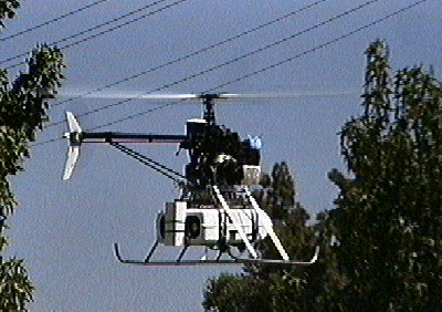
Jumat, 29 April 2016

ROBO SPRING


Hasil gambar untuk MIT Robo springHasil gambar untuk MIT Robo spring 

Hasil gambar untuk MIT Robo spring       Hasil gambar untuk MIT Robo spring 

Hasil gambar untuk MIT Robo spring     Hasil gambar untuk MIT Robo spring 

Hasil gambar untuk MIT Robo spring   Hasil gambar untuk MIT Robo spring     


 Hasil gambar untuk MIT Robo spring    Hasil gambar untuk MIT Robo spring    

Hasil gambar untuk MIT Robo spring  


Hasil gambar untuk MIT Robo spring 


Hasil gambar untuk MIT Robo spring      Hasil gambar untuk MIT Robo spring 


Robots today have been used successfully in many domains, from exploring Mars and finding evidence of water, to mapping the health of coral reefs, to assisting long-distance drivers, to assembling cars. In our course we will pursue a Grand Challenge approach to robotics and create new robot bodies and brains. We are motivated by tasks at the frontier of today's robotic capabilities. We will develop solutions for these tasks that are grounded in state-of-the-art algorithms and systems science for robots. We will implement these solutions and test them using a challenge format.
Our robots will employ sophisticated techniques for perception, navigation, and manipulation to cope with unknown environments, negotiating intricate paths, adapting their next move to obstacles, finding useful objects in the environment, and using them to build a structure. This work will provide our students with the foundations for creating computer systems that interact with the physical world, leading the way from PCs to PRs (personal robots).
The grand challenge for this course is to Gather Materials and Build a Shelter on Mars. Imagine a robot delivered to an uncertain location in a remote and unknown environment such as the surface of Mars, and given an uncertain prior map of the local terrain. Imagine further that construction materials, in the form of distinctively colored blocks in a few discrete sizes, have been similarly delivered and are scattered around the landscape. Some blocks have ended up where intended (i.e., in known locations), whereas others have ended up in unknown locations or may have been lost or destroyed.
Your goal is to design and implement a robot (both its body and its code) that can move about within its new domain, collect blocks, transport them (all at once, in small batches, or even one at a time) to some autonomously-determined construction location, and assemble them into a primitive shelter. The shelter may range from a simple low wall, to a multi-level (stacked) wall, to an "L" or "V" shape, to a room-like structure.

One or more of elements needed to solve the Challenge arise in many other robotic mobile manipulation applications, ranging from autonomous navigation with dynamic obstacles, coordinated manufacturing, searching for and rescuing victims at a disaster area, tidying up a room, clearing the dishes in a cafeteria, delivering packages in an office environment, and fetching items from a stockroom or mailroom. 

ROBO SPRING   MISSION   :

Learning Objectives:

  1. Specify the requirements for an integrated hardware and software design and implementation of an autonomous system performing a specified task;
  2. Critically evaluate choices of design and architectures;
  3. Use kinematics, control theory, state estimation and planning to implement controllers, estimators and planners that satisfy the requirements of specified tasks;
  4. Operate the system for an extended and specified time;
  5. Communicate, orally and in writing, the results of the project design process and the key aspects of the overall project (from concept to end goal).
  6. Collaborate more effectively, for example by having more choices of action, flexibility, and resilience with team process such as decision-making, negotiation and conflict resolution.

Measurable Outcomes

  1. An integrated hardware-software system that performs the desired task;
  2. A written design proposal that specifies and presents the integrated software and hardware design that satisfies design requirements;
  3. Lab reports and briefings that demonstrate mastery of key design skills;
  4. Development and delivery of an oral presentation suitable for a professional audience;
  5. Development and delivery of a debate that evaluates design choices and demonstrates ability to use evidence to argue for conclusions;
  6. Completion of a final report that analyzes the design and its success or failure, and reflects upon learning.


Rabu, 13 April 2016

rope wrapped around and spinning motion capture missions steady string stability for spring AMNIMARJESLOW AL

Hasil gambar untuk extra string concept


String Theory For Dummies 

String theory, often called the “theory of everything,” is a relatively young science that includes such unusual concepts as superstrings, branes, and extra dimensions. Scientists are hopeful that string theory will unlock one of the biggest mysteries of the universe, namely how gravity and quantum physics fit together.

String Theory Features

String theory is a work in progress, so trying to pin down exactly what the science is, or what its fundamental elements are, can be kind of tricky. The key string theory features include:
  • All objects in our universe are composed of vibrating filaments (strings) and membranes (branes) of energy.
  • String theory attempts to reconcile general relativity (gravity) with quantum physics.
  • A new connection (called supersymmetry) exists between two fundamentally different types of particles, bosons and fermions.
  • Several extra (usually unobservable) dimensions to the universe must exist.
There are also other possible string theory features, depending on what theories prove to have merit in the future. Possibilities include:
  • A landscape of string theory solutions, allowing for possible parallel universes.
  • The holographic principle, which states how information in a space can relate to information on the surface of that space.
  • The anthropic principle, which states that scientists can use the fact that humanity exists as an explanation for certain physical properties of our universe.
  • Our universe could be “stuck” on a brane, allowing for new interpretations of string theory.
  • Other principles or features, waiting to be discovered.

    Superpartners in String Theory

    String theory’s concept of supersymmetry is a fancy way of saying that each particle has a related particle called a superpartner. Keeping track of the names of these superpartners can be tricky, so here are the rules in a nutshell.
  • The superpartner of a fermion begins with an “s,” so the superpartner of an “electron” is the “selectron” and the superpartner of the “quark” is the “squark.”
  • The superpartner of a boson ends in “–ino,” so the superpartner of a “photon” is the “photino” and of the “graviton” is the “gravitino.”
Use the following table to see some examples of the superpartner names.
Some Superpartner Names
Standard Particle Superpartner
Higgs boson Higgsino
Neutrino Sneutrino
Lepton Slepton
Z boson Zino
W boson Wino
Gluon Gluino
Muon Smuon
Top quark Stop squark        

Keeping Track of String Theory’s Many Names

String theory has gone through many name changes over the years. This list provides an at-a-glance look at some of the major names for different types of string theory. Some versions have more specific variations, which are shown as subentries. (These different variants are related in complex ways and sometimes overlap, so this breakdown into subentries is based on the order in which the theories developed.) Now if you hear these names, you’ll know they’re talking about string theory!
  • Bosonic string theory
  • Superstring theory (or Supersymmetric string theory)
    • Type I, Type IIA, Type IIB, Heterotic string theories (Type HE, Type HO)
  • M-theory
    • Matrix theory
  • Brane world scenarios
    • Randall-Sundrum models (or RS1 and RS2)
  • F-theory


    Extra Dimensions

    Space is three

    As we indicated before, one of the key consequences of string theory is that there are more dimensions to our world than we imagined. We normally think of our world as four-dimensional. The count goes as follows. We can think of a point in space as being specified by its left-right position, its height, and its depth. Space is therefore three-dimensional. We need three numbers to specify a point in space. We can redo the count in another way. Consider the surface of the earth. When we specify the parallel and great circle of a position on the globe, we can pinpoint the position. The surface of the earth is two-dimensional. But if we had buried a treasure under its surface, we would need to know also how deep it is buried to locate it precisely. Space is again three-dimensional according to this count. A similar count is of course valid for the localization of stars. (Exercise: Count !)

    A special dimension

    Time is the fourth dimension. Indeed, to localize an event, we not only have to specify its precise position in space, but we also need to know when it happened. The extra number we need is the time at which the event happened. That fourth number indicates that space-time is actually four-dimensional. Recall that it was one of the big achievements of special relativity to treat the three dimensions of space and the one dimension of time in the same mathematical framework. Of course, the time dimension still plays a special role, and its role in string theory is similar to its role in our everyday lives, or in the theory of special relativity. The extra dimensions we consider in the following are of the usual spatial sort. -- There are theories that try to make sense of two different times, but we do not consider them here, since they have little or nothing to do with string theory. (Note: crackpots tend to underestimate how seriously professionals have already investigated the ideas they come up with.) We concentrate on extra dimensions in space.

    More than 3+1

    Many scientists had played around with extra dimensions before string theory came along. The idea is natural, since an extra dimension gives some room to play around in, and circumvent theorems that tell you that something is impossible in the 3+1 dimensions that we know off. But people had considered only one extra dimension, since they didn't need more than one. String theory actually tells us there is more than one extra direction. How many more ? Now, that's a tricky question. For years we have thought that string theory needs precisely six extra spatial dimensions -- we will assume this to be true for now, and will explain some more subtly points about how to count the extra dimensions later, when we introduce the concept of M-theory.

    9+1 = 10

    String theory tells us we live in ten dimensions. How does it tell us that, and, importantly, why don't we need to specify ten coordinates when we want to specify the location of a treasure ? The first question is the more difficult one. The mathematics of string theory is such that it leaves us with a dilemma. We either choose to have ten dimensions, or we can choose to accept that there are particles that have a negative probability to be in the universe. The last option (and its formulation in the last sentence) is entirely nonsensical. In other words, nobody has made sense of the notion of "negative probability" up until now, and it is doubtful whether anybody ever will. We now what it means to have a particle somewhere with a small or high likelihood, but not what it means to have it exist with a "negative" likelihood We choose therefore for the lesser evil, and interpret the conundrum as the fact that string theory simply predicts that there are ten dimensions. The problem actually turns out to be a blessing in disguise. We get one more spectacular prediction from string theory.

    Little balls everywhere

    Let's tackle the second question then: where are the six extra dimensions that string theory predicts ? There are different answers to this question, and for starters I discuss only the old one -- I'll come back to an exciting new possibility later. -- The first part of the first answer is that the six extra dimensions are very small, or compact.
    They do not extend very far, in contrast to the three spatial directions that we know of. The extra dimensions are curled up, and in such a way that they are extremely tiny. Since we haven't seen them yet in particle accelerators, we know that they are smaller than 0,000000000000001 meter. The second part of the first answer is that these extra dimensions are everywhere. Indeed, we can think of every point in our space (or kitchen) as not actually being a point, but as being a tiny six-dimensional ball. We do not need to specify the six extra coordinates of a knife in our kitchen, say, because the ball is so tiny that we can easily locate the knife without this extra information. If these dimensions were bigger, we would have seen them long time ago, of course. We would have moreover been able to think much easier in 3D, 4D, or even 9D. (Note that the trick of hiding the extra dimensions is very similar in spirit to hiding the stringy features of strings -- both make use of the fact that the resolution of our measuring devices is too small to make out the new features, as yet.)

    Consequences

    We first of all saw that there is no real problem to having six extra dimensions, as predicted by string theory. That is not to say that they do not have observable consequences. Indeed, once we probe small enough distances, we should be able to see many new interesting phenomena, depending on the shape and size of these extra dimensions. For one thing, we will be able to distinguish particles that run around in these extra dimensions from the ones that don't. Moreover, we will be able to see particles that are actually strings or membranes that are wrapped around some directions of the six-dimensional compact space. And many more interesting phenomena would appear and they might be observed in the next accelerator, depending on how small the six-dimensional compact space is precisely. Let's hope it is not so small that we will never be able to see it in our lifetime.

    Brane worlds

    We treated some aspects of a first answer to the question of where these extra dimensions are hiding. There are other, more modern answers to this question, of which we will treat one in more detail in the chapter on branes. But to introduce branes properly, and to understand how they provide an alternative answer to that question, we first need to introduce a few more properties of string theory.

    Illustrative footnote: An expert points out to me:
    "Dear J,
    I was wandering around the net, and encountered your web site on string theory. It looks very nice, a really thoughtful service.
    One comment: I would quibble with your characterization that string theory predicts 10 dimensions. It is not known to predict
    this--string theory can be formulated in any dimensionality; it is just that one does not have a classical solution with exactly flat space in any dimensionality. The leading effect of venturing away from the critical dimension is that one finds a tree level dilaton potential, which forces us to solve the dilaton and graviton equations of motion nontrivially rather than finding a constant-dilaton
    Min kow ski space solution. Other contributions to the dilaton potential from branes, fluxes, orientifolds, etc. allow us to find compensating forces on the dilaton that fix it. (Or one can consider the linear dilaton background in cases it makes sense,
    as in the 2d string.) Since we don't live in precisely flat space, the critical dimension is not a condition we know to impose
    even phenomenologically. It might transpire that YE POSTING FOR PIT  provides a reason to focus on the critical dimension (I also find this a very plausible possibility), but this is not known at the moment either experimentally or theoretically. Best regards, E"
    To translate: when I say string theory predicts 9+1 dimensions, my colleague believes I make quite a few hidden assumptions (that I may need to explain in lay terms). My colleague is right, of course, and she refers to established technical results to support her case. I include the comment as a footnote, not merely as a fair correction to the above, but also to illustrate that we discuss about how to present string theory results to the layman, and that when we argue, we can use a technical language not accessible to all. To truly do justice to her comment, the task set out for me is to explain the content of the comment (on which experts agree) in understandable terms. I may implement this later on ...


     Hasil gambar untuk extra string concept


    Hasil gambar untuk extra string concept
 Hasil gambar untuk extra string concept 
Hasil gambar untuk extra string concept


Selasa, 12 April 2016

A half spring O max spring not semi ring


Variable Force
( DElta )
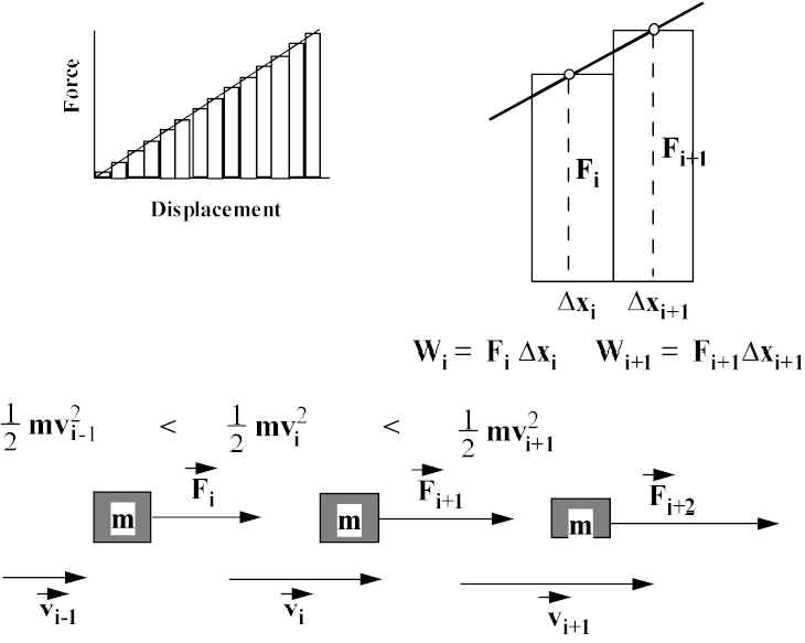
Suppose F acting on a mass m depends on x; e.g., F = kx We divide x into little increments, Dxi, where Fi is the average force over that interval:

wpe25.jpg (29033 bytes)  
Total work going from x1 to x2 = Wtotal = S FiDxi = area under curve!! (C word = integral of F from x1 to x2) and DKE = Wtotal.
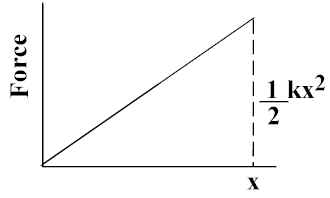
For linear force, F= kx, Area under curve from 0 to xf = wpe26.jpg (1203 bytes).
                        wpe27.jpg (5207 bytes)
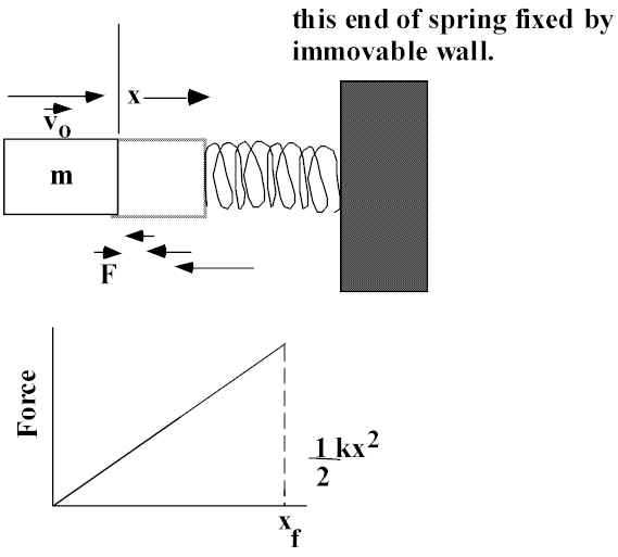
A mass m is moving in a straight line at velocity vo. It comes into contact with a spring with force constant k. How far will the spring compress in bringing the mass to rest?
A spring exerts F proportional to x in both compression and extension (for reasonable x).
wpe28.jpg (21813 bytes)
Change in KE = KEf - KEi = 0 - wpe2A.jpg (790 bytes) mvo^2. Work done by F on mass, W = -wpe2B.jpg (790 bytes) kxf^2. Therefore, kxf^2 = mvo^2 or wpe29.jpg (1687 bytes).
IF we use object and compress spring this same distance (xf = xo) and let go, what is final KE and v? Work done by F on mass, W = +wpe2D.jpg (790 bytes)kxo^2.
Change in KE = KEf - KEi = wpe2E.jpg (790 bytes) mvf^2 + 0. Therefore, mvf^2 = kxo^2. Since xf = xo, we see that: |wpe2F.jpg (813 bytes)| = |wpe30.jpg (824 bytes)|. Since we take a wpe31.jpg (804 bytes), ± does not give direction. Have to go to PICTURE; conclude that wpe32.jpg (1106 bytes)

Running the Stairs to the Stars (Part rangers Bldg -- Basement to 14th floor); Consider POWER.
1. Who could generate the highest instantaneous power?
2. Who could generate the highest average power?
What are "significant" output levels?
Person in good physical shape -- 1/10 hp (75 W) at steady pace. O2 consumption -- 1 liter (1000 cm3)/minute.
Top athlete -- (long distance sports-runners, skiers, bikers) 0.6 hp (~400 W); O2 consumption -- 5.5 liter/minute. Gossamer: (1979) human powered airplane, piloted by world class biker, crossed English Channel -- averaged 190 W (0.3 hp).
FOR approx. 1 minute spurts - 450 - 500 watts.
For fraction of a second -- several kW.
A 70 kg student runs up 2 flights of stairs (Dh = 7.0 m) in 10 s. Compute the student’s output in doing work against gravity in
(a) watts, (b) hp.
(a) W = FDh/t = mgDh/t = (70 kg) (9.81 m/s2) (7 m)/10s = 480 W
(b) W (in hp) = W (in W)/746 = 480/746 hp = 0.64 hp

The express elevator in M Tower A (MISSI) averages a speed of 550 m/minute in its climb to the 103rd floor ( 408.4 m) above ground. Assume a total load of 1.0 x 10³ kg, what is the average power that the lifting motor must provide?
vavg = 550 m/minute x 1 min./60 s = 9.144 m/s.
At constant v, Force to lift = F = mg;
Pavg = Fvavg = (1.0 x 10³ kg)(9.144 m/s) = 89.57 kW = 90 kW.
(takes ~44 s to make trip).

You want to loose weight; You therefore want to:
a)Run the stairs once/day as hard as you can, then hit the chips!, or
b) Sustain an activity that burns ~ 1CALORIE/Minute almost every day for 30-60 minutes and don’t hit the chips!
1 CALORIE = 1 Kilocalorie (4.186 kJ). 1 Kcal/minute = 70 Watts (substantial effort). To loose weight have to exercise and diet!!!


Kamis, 24 Maret 2016

ROBOTIC MOBILITY GROUP MASSACHUSET INSTITUTE OF TECHNOLOGY


Terrain Sensing
 
For mobile robots in rough terrain, the ability to safely traverse terrain is highly dependent on mechanical properties of that terrain. For example, a robot may be able to climb up a rocky slope with ease, but slide down a sandy slope the same grade. With mobile robots being employed for planetary exploration and UGVs being developed for missions on Earth, the ability to predict these mechanical terrain properties from a distance is becoming increasingly important.

This project focuses on:

  • Classifying natural terrain based on visual features, such as color, visual texture, and range data,
  • Learning visual classification on-line, so that a robot can improve its terrain recognition based on its experiences,
  • Autonomously identifying mechanically-distinct terrain classes to eliminate the need for human supervision in establishing the list of terrain classes, and
  • Estimating the mechanical terrain properties associated with each of the terrain classes.
The goal of this work is to be able to set a robot down in a previously unexplored environment, and after driving around for a short period of time have it be able to look out in the distance and predict mechanical properties of the terrain it sees.

Experiments for this project have been performed using a four-wheeled mobile robot in natural outdoor terrain. The robot appeared briefly in a segment of NOVA scienceNOW.

This work has been funded by NASA/JPL through the Mars Technology Program. 


Mobility Prediction with Environmental Uncertainty
The ability of autonomous unmanned ground vehicles to rapidly and effectively predict terrain negotiability is a critical requirement for their use on challenging terrain. Most of the work done on mobility prediction for such vehicles, however, assumes precise knowledge about the vehicle/terrain properties. In practical conditions though, uncertainties are associated with the estimation of these parameters. This work focuses on developing efficient methods that take into account environmental uncertainty while determining vehicular mobility.


Omnidirectional Mobile Robots in Rough Terrain
Mobile robots are finding increasing use in military, disaster recovery, and exploration applications. These applications frequently require operation in rough, unstructured terrain. Currently, most mobile robots designed for these applications are tracked or Ackermann-steered wheeled vehicles. Methods for controlling these types of robots in both smooth and rough terrain have been well studied. While these robots types can perform well in many scenarios, navigation in cluttered, rocky, or obstacle-dense urban environments can be difficult or impossible. This is partly due to the fact that traditional tracked and wheeled robots must reorient to perform some maneuvers, such as lateral displacement. Omnidirectional mobile robots could potentially navigate faster and more reliably through cluttered urban environments and over rough terrain, due to their ability to track near-arbitrary motion profiles. Currently, the drive mechanisms of most omnidirectional mobile robots are designed to perform well in indoor and benign environments.

This project focuses on the analysis, design, and control of omnidirectional mobile robots for use in rough terrain. The robots in this study use active split offset caster drive mechanisms that allow high thrust efficiency during omnidirectional motion and low ground pressures over rough terrain. The design guidelines developed in this research are scalable and applicable for a class of omnidirectional mobile robots.

MIT is collaborating with the Illinois Institute of Technology in constructing a prototype robot to experimentally validate the effectiveness of the design guidelines and controller.

This work has been funded by the U.S. Army Research Office.


Trajectory tracking control for front-steered ground vehicles
The ability to follow a desired trajectory is an important part of many autonomous vehicle navigation and hazard avoidance systems. An important requirement for trajectory tracking controllers is appropriate consideration of the vehicle dynamics, especially with regard to wheel slip. When wheel slip is small, the vehicle dynamics are greatly simplified. When wheel slip does occur, however, it can cause a loss of control, such as in the video below showing a lane change maneuver on snow and ice (please skip to 2 minutes 34 seconds if the video does not automatically do so).
One approach to dealing with the loss of control when wheel slip is large is the use of electronic yaw stability control systems. These systems operate by precisely controlling the brakes at individual wheels to minimize sideslip. Such a system is illustrated in the video above at 3 minutes, 55 seconds. These systems have been shown to reduce the risk of crashes, and fatal crashes in particular.
Electronic stability control systems are effective in reducing wheel slip, but they currently do not consider the effect that stability control has on altering the vehicle path and its ability to avoid collisions with hazards. Also, there is evidence that vehicles can be controlled precisely even with large amounts of wheel slip, as evidenced by the Ken Block Gymkhana video shown below (please skip to 2 minutes, 7 seconds if the video does not automatically do so).
Rather than minimizing wheel slip like a conventional stability controller, we suggest compensating for slip while following a desired trajectory, in a similar manner to expert rally drivers. We recently considered a controller that employs feedback control of tire friction forces to control the position of the front center of oscillation along a desired trajectory. This work was inspired by previous work by Ackermann and is similar to concurrent work being done at Stanford's Dynamic Design Lab.
The trajectory tracking controller is based on a planar half-car model that has one steerable wheel at the front and one wheel at the rear. It is also sometimes called a bicycle model, though it is only 2-dimensional and cannot tip over like a 3-dimensional bicycle. An illustration of this model is given below. Friction force Ff and Fr act at the front and rear wheels, and the speed at the center of gravity (c.g.) is V.
Illustration of half-car vehicle model (aka bicycle model)
The trajectory tracking controller controls the position of a point near the front wheels to follow a desired trajectory. The vehicle behavior is illustrated in the animation below for a sinusoidal trajectory with low acceleration. It can be seen that the front of the vehicle follows the desired trajectory, and the vehicle orientation oscillates a small amount.


Robotics Technology - Mobility


Robotics Technology - Mobility
Industrial robots are rarely mobile. Work is generally brought to the robot. A few industrial robots are mounted on tracks and are mobile within their work station. Service robots are virtually the only kind of robots that travel autonomously. Research on robot mobility is extensive. The goal of the research is usually to have the robot navigate in unstructured environments while encountering unforeseen obstacles. Some projects raise the technical barriers by insisting that the locomotion involve walking, either on two appendages, like humans, or on many, like insects. Most projects, however, use wheels or tractor mechanisms. Many kinds of effectors and actuators can be used to move a robot around. Some categories are:
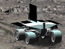
  • legs (for walking/crawling/climbing/jumping/hopping)
  • wheels (for rolling)
  • arms (for swinging/crawling/climbing)
  • flippers (for swimming)
Wheels
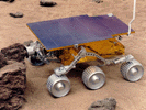
Wheels are the locomotion effector of choice. Wheeled robots (as well as almost all wheeled mechanical devices, such as cars) are built to be statically stable. It is important to remember that wheels can be constructed with as much variety and innovative flair as legs: wheels can vary in size and shape, can consist of simple tires, or complex tire patterns, or tracks, or wheels within cylinders within other wheels spinning in different directions to provide different types of locomotion properties. So wheels need not be simple, but typically they are, because even simple wheels are quite efficient.  Having wheels does not imply holonomicity. 2 or 4-wheeled robots are not usually holonomic. A popular and efficient design involves 2 differentially-steerable wheels and a passive caster.  Differential steering means that the two (or more) wheels can be steered separately (individually) and thus differently. If one wheel can turn in one direction and the other in the opposite direction, the robot can spin in place. This is very helpful for following arbitrary trajectories. Tracks are often used (e.g., tanks).
Legs
While most animals use legs to get around, legged locomotion is a very difficult robotic problem, especially when compared to wheeled locomotion.   First, any robot needs to be stable (i.e., not wobble and fall over easily). There are two kinds of stability: static and dynamic. A statically stable robot can stand still without falling over. This is a useful feature, but a difficult one to achieve: it requires that there be enough legs/wheels on the robot to provide sufficient static points of support.  For example, people are not statically stable. In order to stand up, which appears effortless to us, we are actually using active control of our balance, though nerves and muscles and tendons. This balancing is largely unconscious, but must be learned, so that's why it takes babies a while to get it right, and certain injuries can make it difficult or impossible.  With more legs, static stability becomes quite simple. In order to remain stable, the robot's center of gravity (COG) must fall under its polygon of support. This polygon is basically the projection between all of its support points onto the surface. So in a two-legged robot, the polygon is really a line, and the COG cannot be stably aligned with a point on that line to keep the robot upright. However, a three-legged robot, with its legs in a tripod organization, and its body above, produces a stable polygon of support, and is thus statically stable.  But what happens when a statically stable robot lifts a leg and tries to move. Does its COG stay within the polygon of support? It may or may not, depending on the geometry. For certain robot geometries, it is possible (with various numbers of legs) to always stay statically stable while walking. This is very safe, but it is also very slow and energy inefficient.  A basic assumption of the static gait (statically stable gait) is that the weight of a leg is negligible compared to that of the body, so that the total center of gravity (COG) of the robot is not affected by the leg swing. Based on this assumption, the conventional static gait is designed so as to maintain the COG of the robot inside of the support polygon, which is outlined by each support leg's tip position.  The alternative to static stability is dynamic stability which allows a robot (or animal) to be stable while moving. For example, one-legged hopping robots are dynamically stable: they can hop in place or to various destinations, and not fall over. But they cannot stop and stay standing (this is an inverse pendulum balancing problem).  
A statically stable robot can use dynamically-stable walking patterns, to be fast, or it can use statically stable walking. A simple way to think about this is by how many legs are up in the air during the robot's movement (i.e., gait). 6 legs is the most popular number as they allow for a very stable walking gait, the tripod gait . If the same three legs move at a time, this is called the alternating tripod gait. if the legs vary, it is called the ripple gait. A rectangular 6-legged robot can lift three legs at a time to move forward, and still retain static stability. How does it do that? It uses the so-called alternating tripod gait, a biologically common walking pattern for 6 or more legs. In this gait, one middle leg on one side and two non-adjacent legs on the other side of the body lift and move forward at the same time, while the other 3 legs remain on the ground and keep the robot statically stable. Roaches move this way, and can do so very quickly. Insects with more than 6 legs (e.g., centipedes and millipedes), use the ripple gate. However, when they run really fast, they switch gates to actually become airborne (and thus not statically stable) for brief periods of time. 
Statically stable walking is very energy inefficient. As an alternative, dynamic stability enables a robot to stay up while moving. This requires active control (i.e., the inverse pendulum problem). Dynamic stability can allow for greater speed, but requires harder control.  Balance and stability are very difficult problems in control and robotics, so that is why when you look at most existing robots, they will have wheels or plenty of legs (at least 6). Research robotics, of course, is studying single-legged, two legged, and other dynamically-stable robots, for various scientific and applied reasons.  Wheels are more efficient than legs. They also do appear in nature, in certain bacteria, so the common myth that biology cannot make wheels is not well founded. However, evolution favors lateral symmetry and legs are much easier to evolve, as is abundantly obvious. However, if you look at population sizes, insects are most populous animals, and they all have many more than 2 legs.  
The Spider, a Legged Robot
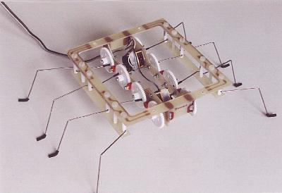
In solving problems, the Spider is aided by the spring quality of its 1 mm steel wire legs. Hold one of its feet in place relative to the body and the mechanism keeps turning, the obstructed motor consuming less than 40 mA while it bends the leg. Let go and the leg springs back into shape. As I write this, the Spider is scrambling up and over my keyboard. Some of its feet get temporarily stuck between keys, springing loose again as others push down. It has no trouble whatsoever with this obstacle, nor with any of the others on my cluttered desk - even though it is still utterly brainless. 
Mobility Limits of the Spider
As the feet rise to a maximum of 2 cm off the floor, a cassette box is about the tallest vertical obstacle that the Spider is able to step onto. Another limitation is slope. When asked to sustain a climb angle of more than about 20 degrees, the Spider rolls over backwards. And even this fairly modest angle (extremely steep for a car, by the way) requires careful gait control, making sure that both rear legs do not lift at the same time. Improvements are certainly possible. Increasing step size would require a longer body (more distance between the legs) and thus a different gear train. A better choice might be more legs, like 10 or 12 on a longer body, but with the same size gear wheels. That would give better traction and climbing ability. And if a third motor is allowed, one might construct a horizontal hinge in the `backbone'. Make a gear shaft the center of a nice, tight hinge joint. Then the drive train will function as before. Using the third motor and a suitable mechanism, the robot could raise its front part to step onto a tall obstacle, somewhat like a caterpillar. But turning on the spot becomes difficult.
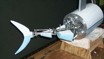
Flying and Underwater Robots
Most robots do not fly or swim.  Recently, researchers have been exploring the possibilities and problems involved with flying and swimming robots.  


Lookahead Navigation for High-Speed Mobile Robots
Recent developments in both defense and commercial sectors have inspired a growing interest in mobile robot navigation technologies. As look-ahead sensing capabilities improve, mobile robots will be able to operate at higher speeds and in more varied environments. This research aims to develop novel planning and control approaches to meet the challenge.

Operation at high speeds requires the anticipation of obstacles and terrain changes. In addition, dynamic effects such as friction saturation and loss of ground contact limit the class of feasible vehicle trajectories. A lookahead naviation system must be capable of planning a feasible trajectory through the sensed environment and controlling the vehicle along that trajectory while remaining robust to terrain changes and dynamic disturbances.

To achieve this kind of forward-looking, versatile control, we are leveraging the prediction and constraint-handling capabilities of model predictive control. Model Predictive Control (MPC) is a flexible, model-based control approach that seeks to minimize an objective function by optimizing a projected set of control inputs over a progressive and forward-looking time horizon. Its ability to explicitly consider constraints, track references, include environmental disturbances, and incorporate multiple actuation methods make it particularly well-suited for the mobile robot navigation problem.