Jumat, 28 Mei 2021

( BASIC_Pro = Before Add System Image Coordinate Programme ) for MARIA Prefer and JESI ISE to The Take off and Air_Pro__ Thanks To Lord Jesus ...Sign On Gen Gate ✍️

BASIC_PRO MARIA PREFER and JESI ISE when the Artificial intelligence and machine learning and deep learning systems for all electronic machine machines are needed a program that aims to add a coordinate image system where when the object is not known, all electronic machine tool systems have provided image responses that provide the right decision for action for AI, Machine Learning and Feel learning for Deeper in an electronic machine integration of policy makers so that 150% decisions can be proven: 1. Maneuvers 2. Shooter 3. Leading 4. Lagging 5. Struggle 6. Defense 7. Shadow force 7 actions Integrated electronics engine is stated absolutely integrated and moving.
✍️πŸ“©πŸ‡ΊπŸ‡Έ⚛️πŸ”› ( Gen.Gate )
Actvision AI , ML , DL , CV --------------------------- Machine learning is a subset of AI, and it consists of the techniques that enable computers to figure things out from the data and deliver AI applications. Deep learning, meanwhile, is a subset of machine learning that enables computers to solve more complex problems.
How AI and Machine Learning Can Improve Robotics --------------------------------------- Artificial intelligence (AI) and machine learning — which is a subset of AI — are opening new opportunities in virtually all industries, plus making frequently used equipment more capable. Not surprisingly, then, AI and machine learning are often applied to robots to improve them. Here are some examples of why an AI robot could be superior to those without the technology.
Industrial Robots With AI Become More Aware of People and Surroundings ------------------------------------- Robots deployed in the industrial sector can help companies get more things done with fewer errors. Of course, safety is key when adding robots in the workplace which is why some AI robotics companies are developing offerings where robots can understand what’s in their environment and react accordingly. Modern Robotics has an industrial robotics system that combines computer vision, AI and sensors. This setup allows the machines to work at full speed unless humans get too close. As such, robots are no longer confined behind cages, but human safety is still a priority. Veo Robotics’ technology enables a robot to dynamically assess how far it must remain from a person to avoid hitting it. There are also autonomous mobile robots (AMR) equipped with AI technology to help the machines learn the layout of a warehouse and steer safely around warehouse obstacles in real time. Those vehicles transport parts and finished products, saving humans from a task that may otherwise cause them to take thousands of steps per day.
Machine Learning Allows Robots to Learn From Mistakes and Adapt --------------------------------------- People get smarter through experience. Through technology such as machine learning, robotics applications may have the same ability. When that happens, they might not need continual time-intensive training from humans. Instead, learning would happen through ongoing use. An example of how you would train a robot via machine learning can be found from the Shadow Robot Company and our work with OpenAI, founded by business tycoons, Elon Musk and Sam Altman. When OpenAI researchers took our hardware, they explored machine learning by creating a robotic system called DACTYL in which a virtual robotic hand learns through trial and error. These human-like strategies were then transferred to the Shadow Dexterous Hand in the natural world enabling it to grasp and manipulate objects efficiently. This shows the feasibility and success of training agents in simulation, without modelling exact conditions so that the robot can gather knowledge through reinforcement and make better decisions intuitively.
Researchers at the University of Leeds are working on a robot that uses AI to learn from mistakes too and evaluates its data gathered over time to make better decisions. The process involves training the bot with approximately 10,000 trial and error attempts, letting it discover which methods are most likely to succeed. Similarly, Australian researchers depended on machine learning to teach humanoid robots to react to unexpected changes in their environment. Simulations indicated that the machine learning algorithm allowed the biped robot to remain stable on a moving platform. Due to machine learning applications like these, the robots of the near future may be more adaptable. If so, they’ll be more valuable to companies that want robots for tasks or environments with high levels of variability. AI Robotics Companies Make Manufacturing More Efficient ---------------------------------------- Manufacturers are figuring out how to rely on AI to improve their workflows. There’s no single way to use AI to help, however. For example, some companies depend on AI to assist with creating components that eventually end up in robots, such as printed circuit boards (PCB). The process of creating a multilayered PCB is exceptionally complex, with each hole in the component requiring a 20-25 micron layer of conductive electro-deposited copper on its walls. As early as the 1990s, products used neural networks to design PCBs. Applying AI during PCB design or manufacturing could bring new robots to the market faster, even if the finished products don’t always use artificial intelligence to work. Some AI robotics companies are also speeding up manufacturing by shortening the time required for robots to learn their tasks. FANUC recently announced a faster way for users to train industrial robots, such as those that pick products from bins. It uses AI to substantially simplify the process of getting robots ready for the warehouse floor. The people involved in the training only need to click images on a screen to teach the bot what to pick up and what to ignore. Then, what if machine learning applications helped an AI robot know when something was wrong with it? Unplanned downtime can be costly and inconvenient for companies, disrupting workflows and restricting profitability. OMRON debuted a self-diagnosing robot that can tell when it needs repairs or routine maintenance. That machine could help manufacturing become more efficient, too, by staving off disruptions caused by failing equipment. AI and Machine Learning Applications Give Robots Greater Potential ------------------------------------- Progress in AI and machine learning robotics is happening quickly. This overview is only a sample of how the two technologies could benefit the robots of the future. People who specialize in robotics, engineering or related fields should stay abreast of developments like these and strive to understand how such advancements could affect their work soon or over the long-term.
______________________________________ AI , ML , DL , CV for electronic true interest future : ------------------------------------- 1. "Artificial Intelligence in Communication Systems" 2. "Microwave and Wireless Communication " 3. cyber-security; 4. Internet of Things; 5. artificial intelligence and machine learning; 6. wireless communication . 7. identyfying for unidentyfying Flying Object vector . Artificial intelligence (AI) has proven its worth in the last decade in solving complex and/or poorly structured problems in a diverse array of applications. Wireless communications has experienced extraordinary growth since the 1990’s, to the extent that it is almost taken for granted today. However, the application of AI in the design, analysis, and maintenance of wireless communications networks is still in its infancy, though in a rapid growth phase. Many papers have been written on the use of AI in both physical and network layers, but there has so far been few convincing arguments for the practical use of AI in wireless communications. In this Special focuss we aim to explore the practical applications of AI within the lower layers of the protocol stack of wireless communications systems. Cross-layer designs will be of particular interest, and trade-offs between complexity and performance will be emphasized. Test-bedding and field-trial descriptions are especially welcome. focuss of interest include, but are not limited to, the following: 1. Non-linear effects in wireless transceiver design; 2. Wireless network resource allocation; 3. IoT and other specialized network design; 4. Localization of wireless devices; 5. Detection and prevention of cyber-security attacks at the wireless network edge; 6. Military communications; 7. AI techniques suitable for online training; 8. Systematic design and adaptation of AI parameters in a dynamic setting; 9. practical applications of AI in wireless communications. 10. controlling dynamic devices from the other place at long distance . Aviation Industry using AI , ML ,DL ,CV aviation industry that could be used to obtain meaningful results in forecasting future actions. This study aims to introduce machine learning models based on feature selection and data elimination to predict failures of aircraft systems. Maintenance and failure data for aircraft equipment across a period of two years were collected, and nine input and one output variables were meticulously identified. A hybrid data preparation model is proposed to improve the success of failure count prediction in two stages. In the first stage, ReliefF, a feature selection method for attribute evaluation, is used to find the most effective and ineffective parameters. In the second stage, a K-means algorithm is modified to eliminate noisy or inconsistent data. Performance of the hybrid data preparation model on the maintenance dataset of the equipment is evaluated by Multilayer Perceptron (MLP) as Artificial Neural network (ANN), Support Vector Regression (SVR), and Linear Regression (LR) as machine learning algorithms. Moreover, performance criteria such as the Correlation Coefficient (CC), Mean Absolute Error (MAE), and Root Mean Square Error (RMSE) are used to evaluate the models. The results indicate that the hybrid data preparation model is successful in predicting the failure count of the equipment. 1. Introduction Reliability and availability of aircraft components have always been an important consideration in aviation. Accurate prediction of possible failures will increase the reliability of aircraft components and systems. The scheduling of maintenance operations help determine the overall maintenance and overhaul costs of aircraft components. Maintenance costs constitute a significant portion of the total operating expenditure of aircraft systems. There are three main types of maintenance for equipment: corrective maintenance, preventive maintenance, and predictive maintenance . Corrective maintenance helps manage repair actions and unscheduled fault events, such as equipment and machine failures. When aircraft equipment fails while it is in use, it is repaired or replaced. Preventive maintenance can reduce the need for unplanned repair operations. It is implemented by periodic maintenance to avoid equipment failures or machinery breakdowns. Tasks for this type of maintenance are planned to prevent unexpected downtime and breakdown events that would lead to repair operations. Predictive maintenance, as the name suggests, uses some parameters which are measured while the equipment is in operation to guess when failures might happen. It intends to interfere with the system before faults occur and help reduce the number of unexpected failures by providing the maintenance personnel with more reliable scheduling options for preventive maintenance. Assessing system reliability is important to choose the right maintenance strategy. Machine learning is a rising technology that is supposed to develop in the future. Machine learning methods are applied in prediction/preventive systems, communications, security, energy management, and so on . The data preparing level is the core module of machine learning and the decision making system. It manages the data to make it useful for decision. The decision making depends on future forecasting, failure event, and availability of equipment . Data mining is a way of classifying and clamping data into comprehensible information. It comprehends the applicable models from a mass of information and adopts different approaches to uncover secret data. Data mining can be defined as knowledge derivation from raw data . Feature selection is a fundamental issue in data mining and machine learning algorithms that focus on the features which are the most relevant to the intended prediction . Features collected from the observation of a circumstance are not all equivalently significant. Normally, operational data tend to be incomplete, insufficient, or partially meaningful or not meaningful at all. Some of them may be noisy, redundant, or irrelevant. Feature selection aims to choose a feature set that is relevant to a specific duty. This problem is a complex and multidimensional issue . Hsu proposed a novel feature selection algorithm based on the correlation coefficient clustering method. It focused on reducing noisy, repeated, or redundant features. The performance in the computational speed and the classification accuracy can be improved through the removal of the irrevelant features. Methods of data processing helps improve the quality of the data and increase the accuracy of data mining, thereby making it more efficient. Data quality is important for the process of information discovery, checking data anomalies, and predicting and analyzing for decision making [9]. Predicting equipment failures are essential to reduce repair and equipment costs and to assess equipment availability . Mass data can be useful for businesses and can guide systems to follow right paths. To boost performance in machine learning algorithms, it is critical that meaningful information be gathered from the dataset. To eliminate noisy and irrevelant data during data preparation, we used K-means clustering algorithm, which is one of the popular unsupervised machine learning algorithms. It defines k number of centroids and allocates every case to the nearest cluster while keeping the centroids small . The “means” in the K-means refers to the averaging of the dataset to find the centroid. This algorithm assigns each case to only a single set. The purpose is to accomplish a high level of similarity within the clusters and low similarly across them . It is used for more effective and better clustering with decreased complexity. There are many studies on maintenance data and forecasting failure rates. Data preparation is a critical step in the feature selection process, and it has a major effect on the success of a machine learning algorithm.
Satellite with AI and CV ************************ Artificial intelligence has been making waves in recent years, enabling us to solve problems faster than traditional computing could ever allow. Recently, for example, Google’s artificial intelligence subsidiary DeepMind developed AlphaFold2, a program which solved the protein-folding problem. This is a problem which has had baffled scientists for 50 years. Advances in AI have allowed us to make progress in all kinds of disciplines – and these are not limited to applications on this planet. From designing missions to clearing Earth’s orbit of junk, here are a few ways artificial intelligence can help us venture further in space. **What are the uses of artificial satellites?** 1. They are used in communication. 2. They are used in weather forecasting system. 3. They are used in GPS (Global Positioning System) 4. They are used to transport instruments and passengers to the space to perform experiments. several challenges must first be addressed to realize these benefits, as the resource management, network control, network security, spectrum management, and energy usage of satellite networks are more challenging than that of terrestrial networks. Meanwhile, artificial intelligence (AI), including machine learning, deep learning, and reinforcement learning, has been steadily growing as a research field and has shown successful results in diverse applications, including wireless communication. In particular, the application of AI to a wide variety of satellite communication aspects have demonstrated excellent potential, including beam-hopping, anti-jamming, network traffic forecasting, channel modeling, telemetry mining, ionospheric scintillation detecting, interference managing, remote sensing, behavior modeling, space-air-ground integrating, and energy managing. This work thus provides a general overview of AI, its diverse sub-fields, and its state-of-the-art algorithms.
PSK = Phase Shift Keying QAM = Quadrature Amplitude Modulation this picture explain difference phase of PSK and QAM .
Model HUB electronic Block
Model Remote Station Block
VSAT Networking
Data Card Electronic Diagram AI Going to CV -------------- Computer Vision can be extensively used to automate space exploration. It can be used in planet tracking, satellite imagery, heavenly body detection, obstacle detection for aircraft navigation and most importantly it reduces the magnitude of risks faced by astronauts during human-space missions. Artificial Inteligence use neural network concept ------------------------------------ Neural Networks find extensive applications in areas where traditional computers don’t fare too well. Like, for problem statements where instead of programmed outputs, you’d like the system to learn, adapt, and change the results in sync with the data you’re throwing at it. Neural networks also find rigorous applications whenever we talk about dealing with noisy or incomplete data. And honestly, most of the data present out there is indeed noisy. With their brain-like ability to learn and adapt, Neural Networks form the entire basis and have applications in Artificial Intelligence, and consequently, Machine Learning algorithms. Before we get to how Neural Networks power Artificial Intelligence, let’s first talk a bit about what exactly is Artificial Intelligence. For the longest time possible, the word “intelligence” was just associated with the human brain. But then, something happened! Scientists found a way of training computers by following the methodology our brain uses. Thus came Artificial Intelligence, which can essentially be defined as intelligence originating from machines. To put it even more simply, Machine Learning is simply providing machines with the ability to “think”, “learn”, and “adapt”. With so much said and done, it’s imperative to understand what exactly are the use cases of AI, and how Neural Networks help the cause. Let’s dive into the applications of Neural Networks across various domains – from Social Media and Online Shopping, to Personal Finance, and finally, to the smart assistant on your phone. You should remember that this list is in no way exhaustive, as the applications of neural networks are widespread. Basically, anything that makes the machines learn is deploying one or the other type of neural network. RADAR and Electronic Warfare future platform **************************** We need confirm BASIC_Pro of Data flowing from radar and electronic warfare (EW) systems to the analyst's screen will determine the course of action in any given mission. Bearing in mind that decisions need to be made, at times in seconds, it's critical for radar and EW systems to quickly sift through that data and turn it into actionable intelligence. To achieve this goal, the defense industry is using artificial intelligence (AI), machine learning (ML), and deep learning (DL) techniques to program these systems and make them into smarter, more autonomous tools. CV ( Computer Vision ) super up ******************************* computer vision is defined as “a subset of mainstream artificial intelligence that deals with the science of making computers or machines visually enabled, i.e., they can analyze and understand an image.” Human vision starts at the biological camera’s “eyes,” which takes one picture about every 200 milliseconds, while computer vision starts by providing input to the machine. This makes it the best case for a class of algorithms called the Convolution Neural Network. The basic building block of a neural network is a neuron, which loosely models the biological neuron. Similar to a biological neuron, an artificial neuron has input channels, a processing body, and output channel . Computer vision tasks include methods for acquiring, processing, analyzing and understanding digital images, and extraction of high-dimensional data from the real world in order to produce numerical or symbolic information, e.g. in the forms of decisions. Understanding in this context means the transformation of visual images (the input of the retina) into descriptions of the world that make sense to thought processes and can elicit appropriate action. This image understanding can be seen as the disentangling of symbolic information from image data using models constructed with the aid of geometry, physics, statistics, and learning theory. The scientific discipline of computer vision is concerned with the theory behind artificial systems that extract information from images. The image data can take many forms, such as video sequences, views from multiple cameras, multi-dimensional data from a 3D scanner, or medical scanning device. The technological discipline of computer vision seeks to apply its theories and models to the construction of computer vision systems. Sub-domains of computer vision include scene reconstruction, object detection, event detection, video tracking, object recognition, 3D pose estimation, learning, indexing, motion estimation, visual servoing, 3D scene modeling, and image restoration.
Computer vision is a sector of Artificial Intelligence that uses machine and Deep Learning to allow computers to “see” and analyze their surroundings. the formulation : 1.Customer Tracking. 2.People Counting. 3.Theft Detection. 3.Waiting Time Analytics. 4.Social Distance. 5.Productivity Analytics. 6.Quality Management. 7.Skill training. 8.Flying Object form RADAR 9.GPS Locater 10.Sattelite Loading Tracking Analytics. this now advances in artificial intelligence and innovations in deep learning and neural networks, the field has been able to take great leaps in recent years and has been able to surpass humans in some tasks related to detecting and labeling objects. One of the driving factors behind the growth of computer vision is the amount of data we generate today that is then used to train and make computer vision better. Computer Vision for Autonomous Robots and AI-ML-DL network as BASIC_PRO amplifier. ************************************* Exploration and engineering of extraterrestrial life is an important and active field of research in the future survival of humans and the life of robotics projects in the field, because the concept of a vehicle, both robotic and human drift, must be able and able to carry out autonomous exploration and engineering that has the potential to impact It is significant in various applications of life on earth and extraterrestrial such as search and rescue operations, detection of undefined objects on earth, monitoring of the earth and extraterrestrial environment, and exploration and enhancement of life on planets other than earth. Such autonomous exploration capabilities are desirable for the Moon and Mars missions , as well as Pluto because remote operations are impractical due to the large transmission delays so new models of transmissions as well as moving materials are required to deliver the transmissions . This kind of work, we can define as an exploration and engineering problem by simultaneously covering the unknown environment, mapping the area, and detecting objects of interest. There are three main challenges present in a complete solution to an exploratory problem. First, the approach must maintain globally consistent maps that move uniformly and possibly with irregular patterns over long distances with intermittent relative and absolute measurement information, such as GPS and magnetometers. Second: the solution must reliably identify potential objects of interest over the widest possible range to minimize time spent sweeping the environment for candidate objects, as well as identify objects of interest in various lighting and undefined and undefined environmental conditions using high-resolution robotic speed cameras and AI. , ML and DL awareness, Improvement and Monitoring as well as real-time maintenance. Multi-Object Detection Along with a tremendous amount of visual data (more than 3 billion images are shared online every day), the computing power required to analyze the data is now accessible. As the field of computer vision has grown with new hardware and algorithms so has the accuracy rates for object identification. 
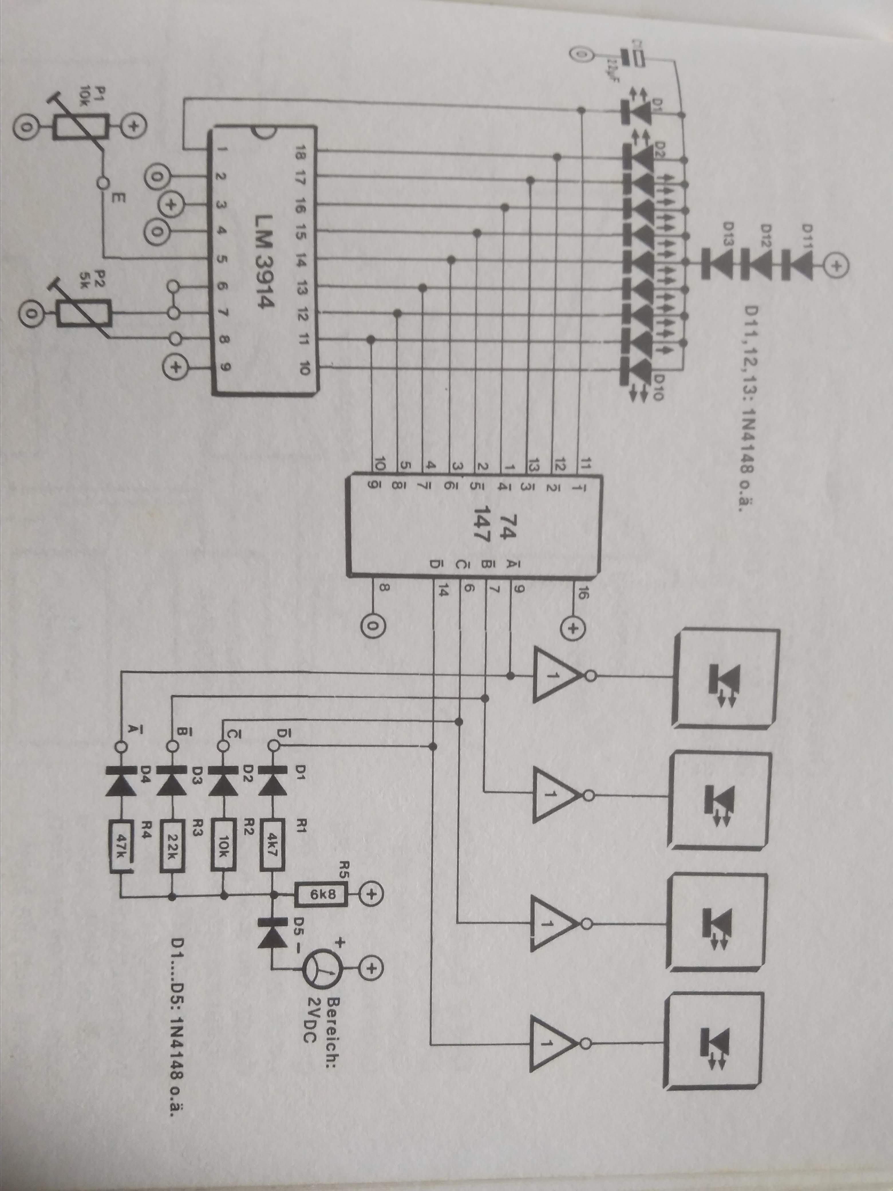
Below I give some examples of network forms that exist in the development of electronic engineering and is also one of the circuits I used when I did my electronics thesis, namely the electronic network of the grid-spot monitor as the origin of the Television monitor as well as the thesis on measuring instruments for observing the potential difference of a car accumulator, namely spots. LM 3914 bars, so I also put a picture here of how Neuro networks in humans are imitated into electr
onic networks or artificial intelligence, let's see some of the forms.. God Bless.
The picture above is a block diagram of a tracking system on a moving satellite. the explanation of the block diagram is that the magnitude of the signal received by the antenna is not the same at any time. The received signal shows the modulation amplitude, where the speed of the transmitting wave will be equal to the speed of the antenna beam around the rotating axis. then this modulating amplitude is detected by the tracking receiver which will generate ripple voltage. in this phase comparator ripple compared to AZ ( Azimuth ) and EL ( Elevation ) reference frequency . The resulting output will be a control signal from the servo system which will move the rotary axis in the direction where the satellite is located. In fact, to rotate the antenna beam, it is not the main reflector that is driven, but the sub reflector which is rotated at a speed of approximately 8.5 to 9.6 revolutions / sec. lets go we look Hybrid Matrix Amplifier ( HMA network forming signal )
letsgo and come on to some examples of networks that move and pay close attention to azimuth and elevation.
πŸ–• WWW and NewsGroup tracking πŸŽ…
**************************************
POWER (Principal_Orientation_Winner_Energie_ Response ) + Awareness_Improvement_Maintenance to be Good Habits and Good Faith. = 1. Education for Awareness 2. Training for Improvement 3. Work for Maintenance 4. Research for MONEY ( Mine_On_Natural_Energy_You) 5. Continouse R & D for long Timing Technical . 6. Faith Support for Strenghtness 7. Blessing From Lord for Long Life Scientific . ***************

Jumat, 19 Februari 2021

Come Back to e_SWEETY ( electronic energy function to all system ) ; Transformer ( AC to AC ) ___ Adapter ( AC to DC )___Converter( DC to DC ) ___Inverter(AC to DC) : All systems on earth require these four forms of energy conversion, especially to run: airplanes, satellites, ships, modern vehicle equipment and smart homes, smart factories and smart phones __ AMNIMARJESLOW GOVERNMENT 2033 ANSEL or ANCELL 030410 __ O*** Gen. Mac Tech and O****x_Gen. CID Star Gate -- at Stability

At a time when the 20th and 21st centuries, energy sources are a runway to increase the degree of human life on earth, there is a lot that needs to be considered and upgraded in this life, especially in the field of discovery of renewable electronic materials and research and design in outer space as well as on other planets. which is several light years from earth. at this time the technology is still based on the engineering technology of the source source of the transformer, analog and digital adapters, converters, inverters. which of course in the future we must be able to continue to the form of electronic energy with materials and systems that are increasingly developing from electronic energy that we will discuss today. Welcome to e_SWEETY ( Study__Work__Easy__Energy__Transform__You )
( 1. Gen . Mac Tech ) ( 2. Gen . CID Star Gate ) ( 3. Gen . CTI Star Forter )
The basic functions of importance for power electronics are (1) power conversion, ac to dc, dc to ac, ac to ac, (2) power conditioning to remove distortion, harmonics, voltage dips and overvoltages, (3) high speed and/or frequent control of electrical parameters such as currents, voltage impedance, and phase angle, efficiency energy transform .
________________________________________________________________________________________________________________________________________________ Some examples of uses for power electronic systems are DC/DC converters used in many mobile devices, such as cell phones or PDAs, and AC/DC converters in computers and televisions. Large scale power electronics are used to control hundreds of megawatt of power flow across our nation. ** TRANSFORMER ___________ A transformer is a passive electrical device that transfers electrical energy from one electrical circuit to another, or multiple circuits. A varying current in any one coil of the transformer produces a varying magnetic flux in the transformer's core, which induces a varying electromotive force across any other coils wound around the same core. Electrical energy can be transferred between separate coils without a metallic (conductive) connection between the two circuits. Transformers are most commonly used for increasing low AC voltages at high current (a step-up transformer) or decreasing high AC voltages at low current (a step-down transformer) in electric power applications, and for coupling the stages of signal-processing circuits. Transformers can also be used for isolation, where the voltage in equals the voltage out, with separate coils not electrically bonded to one another. Transformer look like traffic on round πŸš” circle , lets look example πŸ”“⛽
Since the invention of the first constant-potential transformer in 1885, transformers have become essential for the transmission, distribution, and utilization of alternating current electric power.A wide range of transformer designs is encountered in electronic and electric power applications. Transformers range in size from RF transformers less than a cubic centimeter in volume, to units weighing hundreds of tons used to interconnect the power grid. Various specific electrical application designs require a variety of transformer types. Although they all share the basic characteristic transformer principles, they are customized in construction or electrical properties for certain installation requirements or circuit conditions. In electric power transmission, transformers allow transmission of electric power at high voltages, which reduces the loss due to heating of the wires. This allows generating plants to be located economically at a distance from electrical consumers. All but a tiny fraction of the world's electrical power has passed through a series of transformers by the time it reaches the consumer. In many electronic devices, a transformer is used to convert voltage from the distribution wiring to convenient values for the circuit requirements, either directly at the power line frequency or through a switch mode power supply. Signal and audio transformers are used to couple stages of amplifiers and to match devices such as microphones and record players to the input of amplifiers. Audio transformers allowed telephone circuits to carry on a two-way conversation over a single pair of wires. A balun transformer converts a signal that is referenced to ground to a signal that has balanced voltages to ground, such as between external cables and internal circuits. Isolation transformers prevent leakage of current into the secondary circuit and are used in medical equipment and at construction sites. Resonant transformers are used for coupling between stages of radio receivers, or in high-voltage Tesla coils.
________________________________________________________________________________________________________________________________________________ **** ADAPTER _________ An adapter or adaptor is a device that converts attributes of one electrical device or system to those of an otherwise incompatible device or system. Some modify power or signal attributes, while others merely adapt the physical form of one connector to another. 1. adapter in its internal style guide, namely, use adaptor when referring to devices and adapter when referring to people. 1 : one that adapts. 2a : a device for connecting two parts (as of different diameters) of an apparatus. b : an attachment for adapting apparatus for uses not originally intended. How it works. A simple AC adapter consists of a transformer, a rectifier, and an electronic filter. The transformer initially converts a relatively high-voltage alternating current that is supplied by an electrical outlet to a lower voltage suitable for the device being powered.An adapter card (also known as an expansion card) is simply a circuit board you install into a computer to increase the capabilities of that computer. They are large because of the physical size of the components that they need. With newer technology, and lower power devices, some AC adapters no longer do that, but for larger devices that is likely to be an issue for years to come. One solution is to use a cable extension between the AC outlet and the adaptor . 2. A SanDisk adapter is a PC card you insert into your laptop that lets you transfer data between devices such as phones. The SanDisk adapter lets you insert the phone's memory card to transfer data. AC-to-DC adapters A "power cube"-type AC adapter An AC-to-DC power supply adapts electricity from household mains voltage (either 120 or 230 volts AC) to low-voltage DC suitable for powering consumer electronics. Small, detached power supplies for consumer electronics are called AC adapters, or variously power bricks, wall warts, or chargers. Computer adapters A host controller connects a computer to a peripheral device, such as a storage device, network, or human interface device. As a host controller can also be viewed as bridging the protocols used on the buses between peripheral and computer, and internally to the computer, it is also called a host bus adapter. Likewise, specific types may be called adapters: a network interface controller may be called a network adapter, and a graphics card a display adapter. Adapters for external ports Adapters (sometimes called dongles) allow connecting a peripheral device with one plug to a different jack on the computer. They are often used to connect modern devices to a legacy port on an old system, or legacy devices to a modern port. Such adapters may be entirely passive, or contain active circuitry. A common type is a USB adapter. One kind of serial port adapter enables connections between 25-contact and nine-contact connectors,[2] but does not affect electrical power- and signalling-related attributes.
_______________________________________________________________________________________________________________________________________________ ****** CONVERTER Electronics _____________________ Converters and inverters are electrical devices that convert current. Converters convert the voltage of an electric device, usually alternating current (AC) to direct current (DC). On the other hand, inverters convert direct current (DC) to alternating current (AC). 4-Different Power Converters Introduction to Power Electronic Converters. AC to DC Converters or Rectifiers. Uncontrolled Diode Rectifiers. Single phase half-wave rectifier. ... DC to DC Converters. Step-down Chopper or Buck converter. Step-up Chopper or Boost converter. ... AC to AC Converters. AC/AC Voltage Converters. ... DC to AC Converters or Inverters. These converters are used to regulate and shape an electrical signal in the required form. Among these converters, AC–DC converters, commonly known as rectifiers, are used extensively in renewable energy systems such as grid-connected DC microgrids, grid-connected solar photovoltaic energy conversion systems, etc. Some examples of uses for power electronic systems are DC/DC converters used in many mobile devices, such as cell phones or PDAs, and AC/DC converters in computers and televisions. Large scale power electronics are used to control hundreds of megawatt of power flow across our nation. The big difference between an adapter and a converter is electricity. While the purpose of an adapter is to simply help the plugs on your electronics fit into (or more aptly, adapt to the shape of) foreign outlets, a converter's job is to change the voltage found in an outlet to match that of your devices. There are three major kinds of power supplies: unregulated (also called brute force), linear regulated, and switching. Many common persovonal devices--like an iPhone charger, laptops, and cameras--that people like to travel with can be easily powered up abroad with a simple plug adapter because they are dual voltage devices. Plug adapters do not convert electricity; converters do that, but you won't need one for a dual voltage device. iPhone's charger works both on 120 volt and 220 volt. ... A plug adaptor is all you need, the charger itself can run on any voltage between 100 and 240. Full converter : In the same circuit as above uses 4 thyristors (which is like a diode which turns on only when an external signal is given by us) So that we can control the output voltage of the converter dc output. Semi converter : In the same circuit , 2 thyristors and 2 diodes are used. Power electronics is the application of solid-state electronics to control and convert one form of electrical power to another form such as converting between AC and DC or changing the magnitude and phase of voltage and current or frequency or combination of these. Power electronics converters are widely used in myriad power conversion applications from fraction of volt and power to tens of thousands of volts and power levels. Sometimes it involves multistage power conversion with two or more converters connected in series/parallel or in cascade fashion. The application might be different, but the end goal is primarily driven by five major aspects, such as: energy efficiency, power density, cost, complexity, and reliability, which also influence each other to some extent. In this chapter, various power electronic convertors (AC-DC, DC-AC, DC-DC, and AC-AC) and commonly used circuit and topologies are introduced with their general operating principle.
compare to Human Body Convert Signal ____________________________________
Compare to Electronic Automotive __________________________________
________________________________________________________________________________________________________________________________________________ ********* INVERTER ________ A power inverter, or inverter, is a power electronic device or circuitry that changes direct current (DC) to alternating current (AC). ... The input voltage, output voltage and frequency, and overall power handling depend on the design of the specific device or circuitry. A device that converts direct current electricity to alternating current either for stand-alone systems or to supply power to an electricity grid. An inverter is energy saving technology that eliminates wasted operation in air conditioners by efficiently controlling motor speed. ... In inverter type air conditioners, temperature is adjusted by changing motor speed without turning the motor ON and OFF. According to the output characteristic of an inverter, there can be three different types of inverters. Square Wave Inverter. Sine Wave Inverter. Modified Sine Wave Inverter. The applications areas of inverters such as: Adjustable-speed ac motor drives. Uninterrupted power supplies (UPS) Running appliances of ac used in an automobile battery. power transmission industry such as reactive power controllers and adaptive power filters.
_________________________________________________________________________________________________________________________________________________ WELLCOME e _ SWEETY
( 1. Gen . Mac Tech ) ( 2. Gen . CID Star Gate ) ( 3. Gen . CTI Star Forter )
________________________________________________________________________________________________________________________________________________ πŸͺπŸͺπŸͺπŸͺπŸͺπŸͺπŸͺπŸͺπŸͺπŸͺπŸͺπŸͺπŸͺπŸͺπŸͺπŸͺπŸͺπŸͺ Code of conduct : 1. Time domain for equalize reality network electronic a way . 2. Frequency Domain for equalize simulate network electronic a way 3. Phase domain for equalize micro and nano operation technical network electronic a way 4. hole pole spherical domain for equalize network electronic in energy support . πŸ•Έ️πŸ•Έ️πŸ•Έ️πŸ•Έ️πŸ•Έ️πŸ•Έ️πŸ•Έ️πŸ•Έ️πŸ•Έ️πŸ•Έ️πŸ•Έ️πŸ•Έ️πŸ•Έ️πŸ•Έ️πŸ•Έ️πŸ•Έ️πŸ•Έ️πŸ•Έ️πŸ•Έ️πŸ•Έ️

Jumat, 15 Januari 2021

Hello !! Welcome to electronics RF Signal conditioner is something that is connected in the range and space for the development of 4-dimensional commands in a short software system and simple hardware for the purpose of brainware, electronic machines that can make decisions and think according to the intended target with 1000 percent precision and accuracy as like as Rainbow frequency Windows __ AMNIMARJESLOW GOVERNMENT Link gate __ STAR to Windows Gate .

DREAM INSPIRE CREATION MOMENT ACTION AND REACTION THE PLACE TO PRO LIFE , PRO LIVE AND PRO FUTURE LIVING IN LORD WE HAVE GOT THE HAPPY PLACE Sign In ;1. Gen . CID STAR TIME GATE 2. Gen . Mac Tech __________________________________________________________________________________________________________________________
A radio frequency power amplifier (RF power amplifier) is a type of electronic amplifier that converts a low-power radio-frequency signal into a higher power signal. Typically, RF power amplifiers drive the antenna of a transmitter. In radio transmission, transmitter power output (TPO) is the actual amount of power (in watts) of radio frequency (RF) energy that a transmitter produces at its output. ... The radio antenna's design "focuses" the signal toward the horizon, creating gain and increasing the ERP. example of RF we look at RF transistors are designed to handle high-power radio frequency (RF) signals in devices such as: ... Radio transmitters. Television monitors. RF signals and measure a wide range of signal parameters. ... the capability to measure input and output power on a device, circuit, or system and compute a gain or loss. RF travel make For a 2.4 GHz transmission path to transmit 5 miles, you would need antennas at 9.6 m (31 ft). For 900 MHz at 20 miles (32 km), you would need antennas of at least 46 m (152 ft) to achieve a good signal. In many practical settings, your transceivers may function with a lower antenna height, but the higher the better. The Received Signal Strength Indicator (RSSI) measures the amount of power present in a radio signal. It is an approximate value for signal strength received on an antenna. Measuring the signal strength at the receiving antenna is one way to determine the quality of a communication link. ... The RSSI is measured in dBm. A tuned amplifier that amplifies the signals commonly used in radio communications. Amplifier designs in the radio-frequency (RF) range differ significantly from conventional low-frequency circuit approaches; they consequently require special, distributed circuit considerations. In telecommunications, particularly in radio frequency, signal strength (also referred to as field strength) refers to the transmitter power output as received by a reference antenna at a distance from the transmitting antenna.
The main element of RF sensors based on diode detectors is that it uses diode rectifiers in order to produce an output. The RF power sensors using these diodes make it possible for RF power to get dissipated in a load. The detector then rectifies the voltage signal that appears across the load. RF in wireless communication : RF signals are easily generated, ranging 3kHz to 300GHz. These are used in wireless communication because of their property to penetrate through objects and t ravel long distances. Radio communication depends on the wavelength, transmitter power, receiver quality, type, size and height of the antenna. There are basically three different types of wireless networks – WAN, LAN and PAN: Wireless Wide Area Networks (WWAN): WWANs are created through the use of mobile phone signals typically provided and maintained by specific mobile phone (cellular) service providers. RF detectors really work? Bug detectors, though slightly more complex than camera detectors, are fairly simple to use. Since bugs transmit RF (radio frequency) signals, bug detectors hone in on those signals and indicate that there is a bug present, by lighting up, making a sound, or both . RF detector detect ; A radio frequency (RF) detector is a device used to detect the presence of RF waves either in a wireless or wired (on RF Cable) physical transmission medium. They are also known as RF power detectors or RF responding detectors and are available as devices or modules. Hidden camera detector ; Hidden Camera Detector Professional detectors offer two methods of finding a camera: either they look for that glint from the lens (much like using a flashlight or smartphone), or they detect RF broadcasts from a wireless camera. ... A camera lens should light up in the detector's viewfinder, making it easy to spot. Listening Device Detectors ; A radiofrequency detector can scan for transmitters. Turn off all wireless devices, including smartphones and routers, then slowly and carefully move the bug detector around your home. Anything that's broadcasting a radio signal will be found.
RF power amplifier __________________ A radio frequency power amplifier (RF power amplifier) is a type of electronic amplifier that converts a low-power radio-frequency signal into a higher power signal. Typically, RF power amplifiers drive the antenna of a transmitter. Design goals often include gain, power output, bandwidth, power efficiency, linearity (low signal compression at rated output), input and output impedance matching, and heat dissipation. The basic applications of the RF power amplifier include driving to another high power source, driving a transmitting antenna and exciting microwave cavity resonators. Among these applications, driving transmitter antennas is most well known. The transmitter–receivers are used not only for voice and data communication but also for weather sensing (in the form of a radar). RF power amplifiers using LDMOS (laterally diffused MOSFET) are the most widely used power semiconductor devices in wireless telecommunication networks, particularly mobile networks. LDMOS-based RF power amplifiers are widely used in digital mobile networks such as 2G, 3G, and 4G. Concepts of RF Power Amplification ___________________________________ Introduction RF Power Amplifier design is a complicated task, which very often involves a team of engineers working on its different aspects (system design, circuit implementation and testing, mechanical design, control circuitry – to name a few). In order to synchronize their efforts, all team members have to have a clear understanding of the common goals and methods of their solution. These notes describe basic amplifier requirements, mention approaches for meeting them, and briefly discuss a design flow. To keep them useful for all team members (regardless of their specialty or experience), formulas were avoided in the text and just a few of them are given in the appendix. For the same reason references were deliberately omitted: those who are interested in them can Google the subject or request them from the author.
Power Amplifier Requirements The RF Power Amplifier (PA) is the last component of a transmitter chain. The purpose of a transmitter is to deliver an RF signal with required properties and specified power level to the antenna; and the need for the PA is in amplification of that signal to the level expected at antenna port. That is, in order to do the job, the PA has to meet the following requirements: It has to have sufficient Gain – to amplify RF signal to the level expected at Antenna Port. It is expressed as the difference between input and output RF powers. It has to have sufficient Power Handling Capability – to be able to sustain a RF power level expected by the Antenna Port. Sometimes it is expressed as “dissipated power”, however for high power RF transistors it is often given as “Saturated Power” level. It has to be distortion-free – in order for a system’s receiver to be able to recognize radiated signal. It is expressed as a degree of linearity. It has to be stable – to avoid a creation of oscillations over anticipated variations of external conditions (that is, changes in temperature, load, frequency, DC and RF powers) In addition, it is preferable that PA requirements are to be met efficiently. It is needed to avoid wasting of DC power, and/or to preserve the battery drainage. The problem with efficient amplifiers though, is that they do introduce additional distortions which increase with increasing efficiency. In order to deal with this issue, a number of linearization techniques have been developed. Amplifiers are divided into different classes (Class A to C for controlled current source and Class D and above for switched mode amplifiers) and linearization, specific for a given class, is applied. All these requirements have to be met over the frequency band of operation (which might be 3-to-5 times wider than the occupied bandwidths if linearization techniques are to be used). A detailed description of requirements is given below. 1. Gain For a Power Amplifier, gain is defined as the difference between the power of the RF signal applied to PA input and the one delivered to the antenna port. While this property is the most important for the PA (it is the purpose of Power Amplifiers to create Gain), its actual value is of a lesser importance. Really, the gain of a last stage could be easily increased by adding extra preamplifiers preceding the final stage of a Power Amplifier. That is, the value of the Gain could be reduced for the sake of achieving other parameters (better match, linearity or efficiency). Very often two Gain values are included on PA spec sheets – they are a small signal gain (that is, gain at the significantly reduced level of an input signal; expressed as S21) and a large signal gain (gain at 1 dB compression point). 2. Output Power Power Handling Capability is defined as the maximum power that an amplifier can handle without damage. Its value depends on the size and configuration of a transistor’s die and the proper application of cooling. This parameter should be large enough to sustain an RF power level expected by the Antenna Port. Sometimes it is expressed as “dissipated power” (which is the product of a current flowing through collector/drain and the voltage across the device); however, for high power transistors it is usually given as “output power at 1 dB Compression Point” or “Saturated Power.” 3. Linearity Linearity is the measure of an amplifier’s distortions. Distortions are happening when RF signals with variable envelopes are applied to a nonlinear amplifier; they have to be low enough for the system’s receiver to recognize what the transmitter is sending. Mathematically, the distortions are realized as an interaction between additional spectral components created by the amplifier’s nonlinear transfer function (I-V DC curves). For CW signals their measure is Compression Point or Intercept Point; for digitally modulated signals the figures of merit are Adjacent Channel Power (ACP – the measure of out-of-band interference) and Error Vector Magnitude (EVM – the measure of in-channel distortions). Distortions can be compensated by the application of products with the same amplitude and the opposite polarity to undesirable ones – the process which is called “linearization.” There are two basic approaches to linearization – one of them is called Feedback, where the corrections for creating a distortion-free operation are done at the amplifier’s input (predistorters are operating on this principle), and the other is Feed-Forward, where the corrections are applied to the output of the amplifier. The first approach is cheaper, however it cannot compensate for distortions from heavily compressed amplifiers (above 1 dB compression point). Generic math formulas are given in the appendix. 4. Efficiency Efficiency is a measure of DC energy loss when it is transferred to RF power. In hand-held units, an inefficient PA is draining the battery and producing excessive heat; in high-power stationary units it requires complicated cooling systems and increases the cost of operation. However having ideal sinusoidal RF signal at an amplifier’s output (like in Class A amplifiers) makes the PA lose 50% of its DC power by repeating redundant (positive and negative) information about amplitudes of Voltage and Current; mathematically it is shown by calculating Average Powers, expressed as integrals of instantaneous powers for DC (which is constant) and RF (which is proportional to sin2[t]). In order to increase efficiency, the redundancy of Voltage/Current amplitudes has to be eliminated, which is done with the introduction of a Class B amplifier. In this class a conduction angle is reduced by a biasing amplifier to the origin of its transfer function, which makes the PA transfer only half (positive OR negative) of input RF sinusoids. However, due to the nonlinearities of transfer function (especially pronounced at its origin) – maximum efficiency for this method would not exceed 78%. A better method to increase efficiency is to use a switch modulated by input RF signal. The DC supply of that switch, expressed as Idc*Vdc, is providing a required value for RF output power (when the switch is opened – all DC power is applied to the output load, when it is closed – none is coming to that load; so all DC is applied to the load at intervals directed by input RF data stream). Theoretically this method provides 100% efficiency; the Gain in this model of operation is defined as before (the difference between input and output RF powers); it works because output DC power is higher than input RF one. The obvious issue with this method, however, is that all variations of an input amplitude are lost – so for variable envelopes, one needs to use alternative means of their recovery. Examples of these means are LINC (“Linear amplification with Nonlinear Components” – a method based on idea that any amplitude-modulated signal can be expressed as a sum of two different constant-envelope but phase-modulated signals) and EER (”Envelope Elimination and Restoration” – a method which detects an amplitude of an RF signal, amplifies a phase portion of the RF input signal, and modulates the resulting signal by detected amplitude variation). In order to keep an amplifier’s high efficiency over the range of output powers (vs. achieving it only at the highest level) a technique called Load Modulation is used. For switched amplifiers included in LINC system it is achieved by combining signals from each branch on non-isolated power combiners; however this technique is applied to non-switched amplifiers, too. It is called a Doherty amplifier (the idea of which is to combine very efficient and very linear amplifier on one modulated load), and it allows a reasonable compromise between linearity and efficiency. 5. Stability The RF Power Amplifier has to be stable (that is, oscillation free) over its operational range (over variations in temperature, frequencies, and power levels). Oscillations are caused by a positive feedback from the amplifier’s output; one has to be careful to avoid them or to dump them with additional circuitry. For small signal operations, stable conditions are found from so-called “Stability Factor,” which is a formula derived from S-parameters (parameters describing transfer characteristics of a linear circuit). However, for large signal operations (that is, the most important area of Power Amplifier’s operation) stability has to be determined from Load Pull measurements. Design Flow The typical design of an RF Power Amplifier for a Base Station starts from the requirements supplied by the customer. Based on power and frequency requirements, the output transistors (as a rule – it is a pair of transistors) are to be chosen. Then, based on a budget and requirements, the amplifier’s configuration and class are determined. Input and output matching circuits are designed from load-pull contours, either measured or provided with the transistor’s data sheets. Initial (small signal) simulation of matching circuitry is done based on ideal components and CW input signal. Initial verification of small signal simulations is done on demo boards, provided by the transistors’ manufacturers. Customer requirements should also include a form factor for the amplifier which is a starting point for a mechanical team working on a design of enclosure. From this design an allocated room for a final stage of Power Amplifier is found. Knowing that, a preliminary layout is created and simulated using a large signal simulation with the input waveform supplied by the customer. The first round of simulations is done with still ideal components; at the next round – all known parasitics are to be included. The goal of this simulation is to come up with a PCB layout. When satisfactory results are achieved, EM simulation is conducted in order to include an influence of the enclosure (metal walls and cover) on the layout. The control circuitry team applies their firmware and hardware to the amplifier’s prototype assembled on demo boards. They are to build their final version to the form factor given to them by the mechanical team. Finally, the prototype of the amplifier is assembled into the required enclosure, fine-tuned and then tested using a customer-supplied waveform. In the RF signal chain, the power amplifier (PA) is the active element located between the transmitter signal chain circuitry and the antenna, Figure 1. It is often a single discrete component, one with requirements and parameters which differ from those of much of the transmit chain as well as the receiver circuitry. Many Applications General-purpose RF amplifiers are needed in virtually all wireless designs. Below is just a sample of the broad usage: 4G FDD and TDD base stations 5G base stations Wireless repeaters Distributed antenna systems Infrastructure point-to-point radios Public safety wireless equipment Military radios Test and measurement equipment RF Amplifier Specifications These are the features and specifications to consider in selecting an all-purpose linear RF amplifier. Frequency range: The broader the better for an all-purpose part. Most designs are in the 500-MHz to near 5-GHz range to cover most applications. Gain: This depends on the application, but something in the 10- to 20-dB range is useful. And you want that gain to be the same over a wide frequency range. In most RF amplifiers, the gain will vary somewhat over a wide frequency range. Look for an amplifier with gain flatness over segments over a ±100-MHz range that’s as low as possible, less than about ±0.2 dB. Input/output impedance: 50 Ω, of course. A must standard impedance spec for most RF signal chains. Noise figure: Noise levels are high at these high frequencies. So, noise figure (NF) is usually critical. Remember that NF is a measure of how much noise the amplifier produces. It’s the ratio of the signal-to-noise (S/N or SNR) ratio of the amp input to the signal-to-noise (S/N or SNR) ratio of the amp output expressed in dB. NF = 10log (SNR in/SNR out) A signal chain that adds no noise would have a 0-dB NF. Anything less than about 3 dB is good at these frequencies; the lower the better. Seek out 2 dB as a goal. Output power: This is the maximum power output possible with a 50-Ω load at the highest supply voltage. It’s usually given in dBm, referenced to 1 mW. The typical range is typically 12 to 28 dBm. Third-order intercept and 1-dB compression points: The third-order intercept (IP3) and 1-dB compression (P1dB) points are measures of the linearity and efficiency in an amplifier used for power gain. With most wireless standards using OFDM, CDMA, or some other broadband modulation scheme, good linearity is essential for maximum retention of the data details and best bandwidth usage. As you increase the input power to an amplifier, its output power will rise linearly. At some point the output will begin to flatten or compress, indicating distortion is occurring. Solid-state technology: Amplifiers at these high frequency ranges can be made of CMOS silicon, but more likely they’re made with gallium arsenide (GaAs) or silicon germanium (SiGe). SiGe is generally the more reliable of the two. These compound semiconductors generally perform better than silicon at the higher frequencies. DC power: Most IC RF amplifiers operate from a supply voltage in the 1.8- to 6-V range. Current levels vary with supply voltage and the power generated and can range from 20 mA to over 100 mA. If the amplifier has a standby or low-power mode, current level should drop to no more than a few milliamps. Packaging: Virtually all available amps are surface-mount in tiny packages. DFN and SOT-89 are common, but others are used. Sizes range from 5 × 5 mm down to 2 × 2 mm. Temperature: Most cover the range from −40°C to +85°C or +105°C. _________________________________________________________________________________________________________________________________ RF AMPLIFIER EFFICIENCY BACKGROUND ► The RF Front End (RFFE) is primarily judged by cost, and 4 technical parameters: 1. Output Power 2. Frequency/Bandwidth 3. Linearity 4. Energy Efficiency ► Energy Efficiency is the differentiator ► Usually, the Transmitter/PA consumes the greatest amount of power in the radio, and is the focus for much of the Energy Efficiency development. DEFICIENCY & LOSS : ► All of the circuit components are lossy, dissipating power, reducing energy efficiency. ► Most power losses occur in the device (the controlled current source) itself. ► Simultaneous existence of voltage across, and current through, the device. ► Improvements in energy efficiency are generally made by: 1. Better semiconductor technology 2. Efficiency enhancement schemes FUNDAMENTAL TECHNIQUES ► All techniques for improving efficiency of a device can be broken down and classified: 1. Load Modulation 2. Supply Modulation 3. Waveform Engineering ► Not all enhancement schemes leverage each technique to the same extent. ► Different device technologies exhibit different sensitivities to the techniques. ► Perfectly implemented schemes do not necessarily fully leverage device capabilities. LOAD MODULATION ► In Load Modulation, the load impedance presented to (especially the fundamental frequency) is modified. ► Generally, maximise the voltage swing, the peak-to-peak voltage, across the device. SUPPLY MODULATION ► In Supply Modulation, the supply voltage to the device is modified. ► Generally, the goal is to ensure that the minimum voltage in the RF envelope approaches zero. WAVEFORM ENGINEERING ► In Waveform Engineering, the shapes of the RF waveforms are modified . THEORETICAL LIMIT: MAXIMALLY EFFICIENT ► By applying all 3 techniques optimally, the Maximally Efficient Amplifier can be defined ► Squared-up Voltage and Current waveforms 1. Dissipation in the device is zero, but not necessarily in the other components 2. Anyway, nothing said about how those waveforms are created ► What practical steps can be taken? SUFFICIENTLY EFFICIENT: PRACTICAL LIMIT ► Harmonic Load-Pull measurements, over a range of bias conditions, can explore device performance potential. ► In the worst case, see how much performance is missing with the chosen implementation. ► Alternatively, for example: 1. Identify a complimentary, additional, technique. 2. Identify the most suitable, existing, known, scheme before designing. 3. Implement the device in a novel, highly optimised, scheme. CONCLUSIONS ► Typical off-the-shelf Devices are capable of much better performance than off-the-shelf Enhancement Schemes would have you believe. ► Performing a comprehensive, harmonic Load-pull measurement on a device or technology will, as a minimum, allow you to see just how much performance is missing. ► If efficient RFFE development is your lifeblood, understand which of the 3 fundamental techniques work best for your technology and application. Develop schemes that better leverage them . RF SATCOM design :
The energy efficiency of an RF frontend (RFFE) is a vital characteristic, whether a radio is battery or mains powered. For battery powered, reducing the maximum current drawn from the battery increases the time between charges. For mains powered, important properties such as size, weight and power are dictated by the RFFE efficiency. Consequently, many amplifier architectures and inventions have been developed to minimize wasted energy in the transmitter. Although improving efficiency, some of these rely on theoretically impossible modes of operation, and some fail to fully use the device’s capabilities. fundamental research in RF technology for satellite communication. RF SATELLITE COMMUNICATION? Ecosyatem design : Within this ecosystem we like to act as your preferred partner for applied research and technology developments to enable future design . the focus design is on phased array antenna systems and the building blocks they encompass. Whether you need a break-through step in MMIC design using GaN technology, multipaction-free analogue front-end design, wide steering phased antenna design or RF lens antennas, you can rely on TNO to translate state-of-the art research results into new SatCom technology. MMIC DESIGN AND TESTING the design and testing of Monolithic Microwave Integrated Circuits (MMICs) in GaAs, GaN and SiGe technology. MMICs designs have been successful, ranging from L-band to W-band, with the focus on components for phased array radar front-ends and telecommunication. Examples of such components are high-power amplifiers, multi-function chips (beamformers), mixers, and low-noise amplifiers. FRONT-END ELECTRONICS / BEAM FORMING NETWORK For RF and Β΅Wave communication systems, Front-End electronics is planning design to ranging from the synthesised RF/Β΅Wave signal generation, specific modulation (data/frequency) and power amplification for the transmit signal to low noise amplification, demodulation and high-speed sampling/digitization of the receive signal. TNO has a strong and long heritage in designing such Front-End electronics for all kinds of Radar and Communication systems, optimised for the specific requirements of the application, either for steerable ‘single-beam’ as well as for ‘multi-beam’ array systems. ____________________________________________________________________________________________________________________________ RF for the future of life as the basis for the language of telecommunications Electronics base station keeping teritory
SMART ELECTRONICS WITH TIME WINDOWS
______________________________________________________________________________________________________________________________
Time Windows to SWEETY ( Study_Work_Easy_Energy_Transform_You ) welcome back Star Gate on the Dream_Inspire_Communication_Connection_Contact_Conclusion_Create_Counter Time Windows_Commandment_Closing_Care ) πŸ”‹πŸŒπŸ†™πŸ‘