Flying cars helpful?
They can travel shorter distances to make the same journey . Staying on the theme of lower emissions and greater efficiency. Flying cars can take a much more direct route from point A to point B. This means less fuel is required and the journey times are much quicker as a result when compared to a journey on land.
Flying cars important !
In terms of efficiency, the researchers found that flying electric cars use significant energy to take off and land, but they're highly efficient when cruising. That means they're most efficient overall on longer trips. ... Such a service could replace car trips in areas with heavy congestion or circuitous routes.
Flying cars will work !
Ducted fans enclosed within the wings and piercing the body of the vehicle itself will propel the aircraft vertically. After takeoff, rear-facing fans will thrust it forward so the wings can generate lift and the Aska can fly longer distances more efficiently than a more drone-like design can.
Flying Cars will change the world !
Increasing numbers of flying cars will naturally give rise to a change in the layout and sizes of our cities. ... Because there will be fewer cars on the road, congestion will ease and roads in general should become safer. This will make owning and running a car cheaper. It may even insurance premiums go down.
Flying car definition : “A flying car is a hybrid vehicle that combines fixed wing and rotary wing aircraft capabilities.”
Another way to understand this, is to think of a flying car as being part helicopter, and part airplane.
This is essentially a “mechanical” definition, but there is more to the flying car story than just mechanics. Software development in the field of autonomous systems is a crucial component in making these vehicles not just an interesting research project, but also an appealing business solution for transportation needs. In short, combined wing capabilities make flying cars possible, and autonomy makes them viable.
To fully understand the revolution these vehicles represent, it’s important to recognize the advantages that come with effectively combining fixed wing and rotary wing aircraft capabilities. Let’s look at the pros and cons of a helicopter (rotary flight) and a plane (wing flight), so that we can understand why combining both capabilities is an optimal solution.
- Rey' speederbike, an example of hovercraft in the eight episode of Star Wars .
THE FLYING CARS : THREE CONCEPTS AND A CONCLUSION.
After a long and interesting description of some concepts about the flying car, this is the final article on that hybrid vehicle.
Talking about the flying cars deals with many motoring meanings. The NASA analyzes the definition of the flying cars. Of course, some movies offer representations about that hybrid vehicles. In the previous article, I wrote on points presenting some models from America and Europe which built the history of the flying cars. Through some examples, I tried to understand why people wanted to invent that kind of transport. So how to define the flying cars through three concepts :
A Flying Flivver replica considered as the "Ford T of the air" .
In 2003, a project called Aeoronautics Vehicles System program was developped by the NASA. What was the idea under that large project? Defining the main elements of the flying cars in our modern society, I'm sure SpaceX, Elon Musk' entreprise, was interested in the old concept. Previously, Henry Ford predicted the conception of flying car in 1940 saying some words :
"MARK MY WORD : A COMBINATION AIRPLANE AND MOTORCAR IS COMING. YOU MAY SMILE BUT IT WILL COME."
HENRY FORD
Ford's plane, the Flying Shivver, was far away to complete the standards chosen by the engineers of the NASA. It was a simple aircraft but the inventor of the amazing Tin Lizzie has some original ideas. What are the main elements to build a viable flying car? It would be a quiet and confortable vehicle which is driven/flown at speed of 150/200 mph (or 240/320 km/h). You wouldn't need to have a pilot license but just a driving license without forgetting the affordable prices of the flying cars. We can imagine a flying sportive utilitarian vehicles for your family or a supercar imagining a Renault Espace or a flying Porsche 911.
2- AN INTERMODAL PASSENGER TRANSPORT.
The eighth episode of Star Wars is released on 13th december 2017. George Lucas created an universe around a wealth and original history 40 years ago. The future of the transportation is well represented by the hovercrafts and space ships. Later, Back to the future showed the hovercrafts in details when Marty comes in the future in the second opus.
I mentioned the hovercrafts and not the roadable aircrafts. What is the hovercraft? We can define it as a personnal vehicle which flies at a constant altitude above the ground. In other words, it would be define like a flying car. What is the difference with a roadable aircraft? It is a flying car who can be driven on the roads and a plane with wheels which flies on the atmosphere. Once I asked to science what where his feelings when he was inside one of the flying car built by Taylor. He had answered me simply as you can see it below.
Finally, the flying hovercraft doesn't need wheels to fly freely in the air. We can divide the hovercrafts is two categories. The maritime hovercrafts flew on the water and can be driven on the roads whereas the flying hovercrafts are imaginative hybrid vehicles in the retrofuturism, a social artwork about the future of the transportation.
3-AN ENVIRONMENTAL AND ENGINEERING HYBRID VEHICLE.
More than a Convair 116, a flying car includes complex environmental and aeronautical regulations .
Defining a flying car means to know the environmental regulations and aeronautic rules around the concepts of the cars and the planes. We enter into a new electric motoring era after a long and interesting development of the diesel engines. The environmental regulations are becoming more important with some initiatives in the big cities. The T-charge (around £10) will be add to the Congestion charges in London. The old cars aged of 20 years will be banned in Paris too.
THE FLYING CARS WOULD BE ABLE TO RESPECT THESE ENVIRONMENTAL RULES ON THE ROADS.
The flying cars would be able to respect these environmental rules on the roads. After pointing out the terrestrial pollution, we have to think of the atmospheric pollution as the naval engineers have done in the shipping. The atmospheric busy corridors became a real problem in the transport. You have to fly on invisible roads in the air too. How to manage to introduce the flying cars in the air which the pollution is increased by the traffic jam?
Creating new rules for personal air vehicles would be a solution. There are some advantages and inconveniences. Increasing the numbers of safety rules is a concret goal but a long issue. The Federation Internationale automobile (FIA) tries to improve the motoring safety on the roads. The results of the new regulation to drive safely are a long process. Moreover, the aeronautical rules are so complex too. Finding a harmonious compromise stays the best solution.
Some drivetribers told it's important the engines of the flying cars have to be powerful keeping a certain stability for the passengers. Indeed, landing on the roads is not easy for planes. They need a certain distance without mentioning the noises of the engines in an urban environment. Finally, the flying cars would be a vertical takeoff and landing vehicle called briefly a VTOL.
System' okey !
What is a flying car? Is it a pointless car . Is it a real concept as we saw it with the Taylor aerocar or the new aeromobil 3.0? Is it an old concept imagined by a former engineer from Ford in 1917? Defining a large and theorithical concept is hard because you can develop different ideas about the flying cars. Would you want to have a roadable aircraft or a hovercrafts with wheel or not? Anyway, a flying car is a personal air vehicle, an intermodal passenger transport and an environmental and engineering hybrid vehicle .
---------------------------------------------------------------------------------------------------------------------------------------------------------
Controlling free flight of a robotic fly using an onboard vision sensor inspired by insect ocelli
_________________________________________________________________________________________________
Scaling a flying robot down to the size of a fly or bee requires advances in manufacturing, sensing and control, and will provide insights into mechanisms used by their biological counterparts. Controlled flight at this scale has previously required external cameras to provide the feedback to regulate the continuous corrective manoeuvres necessary to keep the unstable robot from tumbling. One stabilization mechanism used by flying insects may be to sense the horizon or Sun using the ocelli, a set of three light sensors distinct from the compound eyes. Here, we present an ocelli-inspired visual sensor and use it to stabilize a fly-sized robot. We propose a feedback controller that applies torque in proportion to the angular velocity of the source of light estimated by the ocelli. We demonstrate theoretically and empirically that this is sufficient to stabilize the robot's upright orientation. This constitutes the first known use of onboard sensors at this scale. Dipteran flies use halteres to provide gyroscopic velocity feedback, but it is unknown how other insects such as honeybees stabilize flight without these sensory organs. Our results, using a vehicle of similar size and dynamics to the honeybee, suggest how the ocelli could serve this role.
Introduction example theory to fly cars ROBOT as like as drone tech
___________________________________________________________________
Flying robots on the scale of and inspired by flies may provide insights into the mechanisms used by their biological counterparts. These animals' flight apparatuses have evolved for millions of years to find robust and high-performance solutions that exceed the capabilities of current robotic vehicles. Dipteran flies, for example, are superlatively agile, performing millisecond turns during pursuit or landing inverted on a ceiling . Moreover, these feats are performed using the resources of a relatively small nervous system, consisting of only 105–107 neurons processing information received from senses carried onboard. It is not well understood how they do this, from the unsteady aerodynamics of their wings interacting with the surrounding fluid to the sensorimotor transductions in their brain . An effort to reverse-engineer their flight apparatus using a robot with similar characteristics could provide insights that would be difficult to obtain using other methods such as fluid mechanics models or experimentally probing animal behaviour. The result will be robot systems that will eventually rival the extraordinary capabilities of insects.
Creating a small flying autonomous vehicle the size of a fly such as that shown as like as honey bee .As vehicle size diminishes, many conventional approaches to lift, propulsion, sensing and control become impractical because of the physics of scaling. For example, propulsion based on rotating motors is inefficient, because heat dissipation per unit mass in the magnetic coils of a rotary electric motor increases , where is some characteristic length of the vehicle such as wingspan. Combined with increased friction losses owing to an increased surface-to-volume ratio, exacerbated by the need for significant gearing, this results in very low power densities in small electromagnetic motors. In addition, the lift-to-drag ratio for fixed aerofoils decreases at small scales because of the greater effect of viscous forces relative to lift-generating inertial forces at low Reynolds numbers.
A robot the size of a fly uses a light sensor to stabilize flight, the first demonstration of onboard sensing in a flying robot at this scale. (inset) The visual sensor, a pyramidal structure mounted at the top of the vehicle, measures light using four phototransistors and is inspired by the ocelli of insects (scale bar, 5 mm). (main) Frames taken at 60 ms intervals from a video of a stabilized flight in which the only feedback came from the onboard vision sensor. The sensor estimates pitch and roll rates by measuring changes in light intensity arriving from a light source mounted 1 m above (not shown). This is used in a feedback loop actuating the pair of flapping wings to perform continuous corrective manoeuvres to stabilize the upright orientation of the vehicle, which would otherwise quickly tumble. A wire tether transmits control commands and receives sensor feedback, acting as a small disturbance that does not augment stability.
From the perspective of autonomous flight control, an ocelli-inspired light sensor is nearly the simplest possible visual sensor, minimizing component mass and computational requirements. A number of previous studies have considered ocelli-inspired sensors on flying robots, insect-sized or larger. In it was shown that an adaptive classifier could be used to estimate the orientation of the horizon from omnidirectional camera images. In the absolute direction of the light source or horizon relative to the vehicle was estimated. But whereas aligning to the absolute direction of a light source or horizon may be a valid approach for larger aircraft that fly above obstacles so there is a relatively clear view to the horizon, smaller vehicles may fly near buildings, under foliage or indoors. In these conditions, the horizon may be obstructed. This causes the direction of light sources to vary significantly . A control law that aligned the vehicle with a light source would most likely yield a tilted vehicle under these conditions, leading to significant lateral acceleration and dynamic instability.
In this work, we so alternative approach in which a feedback controller applies torque in proportion to angular velocity of the motion of the source of light. This has two benefits. First, it avoids the need for the light source to be directly above for the sensor to produce a useful result. Second, we show that an angular velocity estimate is all that is needed to stabilize the upright orientation of our flapping-wing robotic fly and many flying insects. The first was confirmed by previous work, inspired by observations of derivative-like responses in insect ocelli , that showed that ocelli simulated in a virtual environment can estimate angular velocity about the pitch and roll axes, regardless of initial orientation . The results also suggested that a linear ocelli response cannot estimate other vehicle motion parameters such as absolute attitude. A motor controller was described that computed a time integral of the ocelli angular velocity estimate. Although this did not require the light to arrive from a known direction, an estimate computed in this manner would slowly drift because of accumulated sensor noise. Here, we build on that work to suggest an alternative approach in which the angular velocity estimate is instead used directly in a feedback controller. By applying torque in proportion to angular velocity only, it is possible to harness this vehicle's flapping-wing dynamics to achieve a stable upright attitude that does not drift and that does not require absolute estimate of attitude.
Sensor and robot fly
____________________
The design of the ocelli sensor : Each sensor is inclined roughly 30° above the horizon and captures defocused light from an angular field spanning approximately 180° that is nearly circularly symmetric. The ocelli design consists of four phototransistors soldered to a custom-built circuit board that is folded into a pyramid shape. Each of the four light detectors consists of a phototransistor (KDT00030 from Fairchild semiconductor) in a common-emitter configuration in series with a 27 kΩ surface-mount resistor. The phototransistor has an infrared cut-off filter, reducing its sensitivity to the bright infrared lights emitted by the motion capture system used to measure flight trajectories. The voltage reading is taken from the collector of each transistor and rises with increasing luminance.
Robotic fly mechanical characteristics
______________________________________
The flying vehicle used in this work is actuated by a pair of independently moving wings. By altering signals to the piezoactuators driving the wings, they can produce sufficient lift to take-off, as well as produce ‘pitch’ and ‘roll’ torques independently . We define a right-handed coordinate system for the body in which, with the wings extending laterally along the y-axis and the body axis hanging downwards in the negative z-direction, the x-axis (roll) points forward, the y-axis (pitch) points to the left and the z-axis (yaw) points upwards. Roll torque is induced by varying the relative stroke amplitudes of the left versus right wing. Pitch torque is induced by moving the ‘mean stroke angle’—the time-averaged angle of the forward–backward motion of the wings—in front (+x) or behind (−x) the CM . Yaw torque can also, in principle, be modulated , but we do not use this capability in this study.
Attitude stabilization using velocity feedback
__________________________________________________
We show that knowledge of absolute vehicle attitude is not required to attain stability. Instead, only angular velocity feedback or ‘rate damping’ is needed. More formally, the torque controller : T = - k d w
where ω is the angular velocity, is sufficient to stabilize the fly in the upright orientation.
This result holds under the following assumptions:
(1) Vehicle motions depend only on stroke-averaged forces, that is, forces and torques averaged over the time period of each wing stroke.
(2) Aerodynamic drag on the wings is proportional to airspeed in both the forward (x) and lateral (y) directions, with an equal proportionality constant for both directions.
(3) The vehicle is symmetric about its x–z plane.
---------------------------------------------------------------------------------------------------------------------------------------------------------
Dynamics Modeling and Control of a Quadrotor with Swing Load
______________________________________________________________
The example simple quadcopter electronic circuit :
aerial robots have many applications in civilian and military fields to be good inteliggent transport . For example, of these applications is aerial monitoring, picking loads and moving them by different grippers. In R&D, a quadrotor with a cable-suspended load with eight degrees of freedom is considered. The purpose is to control the position and attitude of the quadrotor on a desired trajectory in order to move the considered load with constant length of cable. the purpose of this research is proposing and designing an antiswing control algorithm for the suspended load. To this end, control and stabilization of the quadrotor are necessary for designing the antiswing controller. Furthermore, this paper is divided into two parts. In the first part, dynamics model is developed using Newton-Euler formulation, and obtained equations are verified in comparison with Lagrange approach. Consequently, a nonlinear control strategy based on dynamic model is used in order to control the position and attitude of the quadrotor. The performance of this proposed controller is evaluated by nonlinear simulations and, finally, the results demonstrate the effectiveness of the control strategy for the quadrotor with suspended load in various maneuvers.
Quadrotor is a rotorcraft whose flight is based on rotation of two pairs of rotors that rotate opposite to each other. the different movement of quadrotor is created by a difference in the velocity of rotors. If the velocity of rotor 1 (or 2) decreases and the velocity of rotor 3 (or 4) increases, then the roll (or pitch) motion is created and the quadrotor moves along the -axis (or the -axis). Moreover, a quadrotor is an aerial robot which has the potential to hover and take off, fly, and land in small areas. In addition, this robot has applications in different fields, among which are safety, natural risk management, environmental protection, infrastructures management, agriculture, and film protection. Moreover, a quadrotor is an underactuated system since it has six degrees of freedom and only four inputs. However, a quadrotor is inherently unstable and it can be difficult to fly. Thus, the control of this nonlinear system is a problem for both practical and theoretical interest. Many control algorithms are tested and implemented on this aerial robot in order to stabilize and move in different tasks. Among these algorithms are classic control, linear and nonlinear state feedback control, sliding mode control, back stepping control, and fuzzy and neural network control. In 2010, Vazquez and Valenzuela designed a nonlinear control system for the position and attitude control based on the classic control PID; indeed, the quadrotor altitude is controlled by a PI-action controller, .implemented a Linear Quadratic Regulator (LQR) controller for the position control of the quadrotor . In 2004, Hoffmann proposed a sliding mode method for the altitude control and an optimal control method for the attitude control. But many difficulties occurred because of motor vibrations in the high thrust and the chattering phenomena. Also, for realizing the robust control of the quadrotor, a back stepping control algorithm is proposed in [4]. This algorithm could estimate disturbances online and, so, they could improve the robustness of system. Erginer and Altug in 2012 performed dynamics modeling and control of a quadrotor. They obtained the dynamic model of the quadrotor by Newton-Euler method and controlled the quadrotor using a hybrid fuzzy-PD control algorithm. In 2008, Raffo et al. implemented a nonlinear algorithm to control and stabilize the angular motion of the quadrotor. The simulation results show that this nonlinear algorithm can eliminate disturbances and stabilize the rotation motion of the quadrotor
So, different control methods have been proposed to control these robots since the suspended load significantly alters the flight characteristics of the quadrotor. These methods are divided into feedback and feed-forward approaches. Feedback control methods use measurements and estimations of system states to reduce the vibration, while feed-forward approaches change actuator commands for reducing the oscillation of system. The feed-forward controller can often improve the performance of feedback controller. Thus, proposing feed-forward algorithms can lead to more practical and accurate control of these systems. One effective feed-forward method is the input shaping theory which has proven to be a practical and effective approach of reducing vibrations . Also, several methods are proposed in order to minimize the residual vibration. Smith proposed the Posicast control of the damped oscillatory systems which is a technique to generate a nonoscillatory response from a damped system to a step input. This method breaks a step of a certain magnitude into two smaller steps, one of which is delayed in time . Swigert proposed shaped torques techniques which consider the sensitivity of terminal states to variation in the model parameters. Recently, in the control of overhead cranes, This moment solved a minimum time control problem for swing free velocity profiles, which resulted in an open loop control .
--------------------------------------------------------------------------------------------------------------------------------------------------------
Dynamics Modeling
_________________
The quadrotor slung load system . It is considered to be a system consisting of two rigid bodies connected by massless straight-line links which support only forces along the link. The system is characterized by mass and inertia parameters of rigid bodies and suspension’s attachment point locations.
In this section, dynamics equations of the quadrotor slung load system are presented by Newton-Euler method. The following assumptions are made for modeling the quadrotor with a swinging load.
(i)Elastic deformation and shock of the quadrotor are ignored.
(ii)Inertia matrix is time-invariant.
(iii)Mass distribution of the quadrotor is symmetrical in the - plane.
(iv)Drag factor and thrust factor of the quadrotor are constant.
(v)Air density around of the quadrotor is constant.
(vi)Thrust force and drag moment of each propellers are proportional to the square of the propeller speed.
(vii)Both bodies are assumed to be rigid. This assumption excludes an elastic quadrotor and rotor modes such as flapping and nonrigid loads.
(viii)The cable mass and aerodynamic effects on the load are neglected.
(ix)The cable is considered to be inelastic.
These assumptions are considered to be sufficient for the realistic representation of the quadrotor with a swinging load system which is used for a nonaggressive trajectory tracking.
look like concept to cars fly :
1. Aerodynamics of Rotor and Propeller
2. Dynamics Equations of Motion : a. Kinematics Equation of Quadrotor
b. Newton-Euler Equation of Quadrotor
c. Lagrange Equation of Quadrotor
d. Model Verification
3. Controller Design : a. Position and Attitude Control of Quadrotor
b. Simulation Results of Designed Position and Attitude Controller
c. Antiswing Control of Quadrotor
d. Simulation Results of Designed Antiswing
4. final concept : the problem of the quadrotor flying is addressed with a suspended load which is widely used for different kinds of cargo transportation. The suspended load is also known as either the slung load or the sling load. Also, flying with a suspended load can be a very challenging and sometimes hazardous task because the suspended load significantly alters the flight characteristics of the quadrotor. So, many different control algorithms have been proposed to control these systems. To this end, dynamic model of this system was obtained and verified by comparing two Newton-Euler and Lagrange methods. Next, a control algorithm was presented for the position and attitude of the quadrotor. In this algorithm, swinging object’s oscillation may cause danger in the work space and it can make instability in the quadrotor flight. Using comprehensive simulation routine, it was shown that this designed controller could control the robot motion on the desired path but could not reduce the load oscillation in noncontinuous and nondifferentiable paths. To deal with this issue, a feed-forwarded control algorithm was introduced for reducing or canceling swinging load’s oscillation. This controller was designed by implementing the input shaping theory which convolves the reference command with a sequence of impulses. Finally, it was shown that the feed-forward controller could actively improve the performance of the feedback controller.
--------------------------------------------------------------------------------------------------------------------------------------------------------
Flying cars could cut emissions, replace planes, and free up roads
__________________________________________________________________
we need necessary technology and practical uncertainties beyond the cars’ promising physics mean that they may not arrive in time to be a large-scale solution to the energy crisis and congestion – if at all.
How to make a car fly
It might at first seem crazy that a flying car could be more efficient than a road car, especially when conventional planes have such a reputation as gas guzzlers. But flying isn’t inherently inefficient – after all, birds can fly between continents without eating. There are many ways to make a car fly, but most are too problematic to get off the ground. Perhaps the most promising option is that taken in this study, based on the physics of vertical take-off and landing (VTOL) aircraft . VTOL, something like a Harrier Jump Jet probably springs to mind, with two huge engines directing thrust that can be tilted vertically or horizontally. But these much smaller and lighter flying cars operate differently, with lots of tiny electric fans blowing air from many places. This fast-developing distributed electric propulsion (DEP) technology is key for efficiency when cruising, and it also creates possibilities for quieter take-off and hovering, as multiple small noise sources can be better managed.
Wing and propeller design can also be optimised to be long, thin, and have lots of moving surfaces, just as birds do to make their flying efficient. The aim of all of these technical enhancements is to achieve maximum lift for minimum drag – the force that opposes an object’s motion through air and slows it down. A better lift-to-drag ratio means lower power consumption, and therefore lower emissions.
These energy-saving innovations make cruising a breeze – but they don’t help much with take-off, hovering, or landing, which are still inherently inefficient. So while VTOL flying vehicles are still viable for short intra-city travel and pizza deliveries, they will not solve the energy crisis.As journey distance increases, so too do the efficiency gains over stop-start road cars, which have to deal with rolling resistance and less efficient airflow.
Problems in practice
In focusing entirely on the physics of flying cars, the paper steers clear of a number of practicalities that must be considered before we embrace VTOL flying cars as a sustainable form of transport for the future. For example, it is important to consider the carbon costs of production, maintenance and down time, known as Life-Cycle Analysis (LCA). Electric vehicles have been criticised for both the energy and environmental costs of mining primary materials for batteries, such as lithium and cobalt. Added infrastructure required for flight may worsen the problem for flying cars. And of course, a grid powered by low-carbon sources is essential to make battery-powered vehicles part of the solution to our climate crisis.
Aircraft also have highly stringent criteria for maintenance and downtime, which can often offset gains in performance and emissions. As an entirely new breed of planes, it’s impossible to predict how much it might cost to keep them air-worthy.
-------------------------------------------------------------------------------------------------------------------------------------------------------
Applications of robotics and artificial intelligence to reduce risk and improve effectiveness
_____________________________________________________________________________________________
1.Companion robots
2.Robots in medicine
3.Robots Drone Tech
4.Retail robots
5.SoftBank Robotics
6.Military robots
7.Delivery robots
8.Food robots
Rotary Wing Aircraft
The primary advantage of a rotary wing is its capacity for vertical take-off and landing (VTOL). Why is this an advantage? Because it removes the need for a runway. As WIRED recently noted, “VTOL technology means aircraft can theoretically take off and land almost anywhere, making them far more flexible.”
In addition to VTOL capabilities, another benefit is ease of control. A helicopter can hover in place pretty accurately, which makes it safe to navigate an urban environment where you might need to stop at several waypoints, and where speed needs to be constantly modulated to respond to external conditions.
So what’re the disadvantages of rotary wing aircraft?
Inefficiency: Hovering in place requires a lot of power to keep the rotors turning to generate the required lift. As a consequence, the allowed payload is drastically reduced, and is the flight time.
Lack of Speed: Rotary wing vehicles are considerably slower than airplanes.
Noise: Rotating blades are very noisy.
Control challenges: Helicopters have a major flaw—if they should lose power, you need a highly-trained helicopter pilot who can execute autorotation to land the vehicle.
Fixed-Wing Aircraft
Let’s now consider fixed-wing aircraft (aka a “typical” airplane). The advantages of fixed-wing aircraft are numerous:
Speed: An airplane goes much faster than a helicopter.
Efficiency: Instead of using a motor to spin the blades, a fixed-wing aircraft uses its motion through the air to keep air flowing through the wings and generate lift.
Payload and distance: Thanks to its speed and efficiency, this vehicle can carry much heavier payloads and travel longer distances than a rotary wing.
Control: If motors fail, the vehicle will not fall from the sky; a pilot still has control and can take it to the ground safely.
As to the main disadvantages of fixed-wing aircraft, there are two:
They require long runways for takeoff and landing.
Hover is not possible, making air traffic operations trickier in the presence of many vehicles.
It should be noted that the features that a flying car utilizes from a fixed-wing aircraft and a rotary wing aircraft are not necessarily a perfect reconciliation; noise and weight disadvantages of a rotary wing vehicle remain. But it’s pretty close to ideal, and it’s why flying cars represent such a compelling mechanical breakthrough.
If you want to know more about the technical aspects of path planning, controls, flight estimation, and autonomous flight is the place for you to learn the technical skills, alongside the tools you need to create real-world applications.
The VTOL Multirotor
There are two visions of the flying car. The most common is VTOL — vertical takeoff and landing — something that may have no wheels at all because it’s more a helicopter than a car or airplane. The recent revolution in automation and stability for multirotor helicopters — better known as drones — is making people wonder when we’ll get one able to carry a person. Multirotors almost exclusively use electric motors because you must adjust speed very quickly to get stability and control. You also want the redundancy of multiple motors and power systems, so you can lose a rotor or a battery and still fly.
This creates a problem because electric batteries are heavy. It takes a lot of power to fly this way. Carrying more batteries means more weight — and thus more power needed to carry the batteries. There are diminishing returns, and you can’t get much speed, power or range before the batteries are dead. OK in a 3 kilo drone, not OK in a 150 kilo one.
Lots of people are experimenting with combining multirotor for takeoff and landing, and traditional “fixed wing” (standard airplane) designs to travel any distance. This is a great deal more efficient, but even so, still a challenge to do with batteries for long distance flight. Other ideas including using liquid fuels some way. Those include just using a regular liquid fuel motor to run a generator (not very efficient) or combining direct drive of a master propeller with fine-control electric drive of smaller propellers for the dynamic control needed.
Another interesting option is the autogyro, which looks like a helicopter but needs a small runway for takeoff.
The traditional aircraft
Some “flying car” efforts have made airplanes whose wings fold up so they can drive on the road. These have never “taken off” — they usually end up a compromise that is not a very good car or a very good plane. They need airports but you can keep driving from the airport. They are not autonomous.
Robocars offer an interesting alternative. You can build a system where a robocar takes you from home to the best local short airstrip, taking you right out to an autonomous aircraft that is sitting waiting. You transfer, and it immediately takes off and flies you to another short airstrip, where another robocar awaits you. This allows you to travel in a car that’s a car and a plane that’s a plane, with no compromise.
The big challenges
Automating the intense level of safety and equipment reliability
In general, planes today are not fast modes of travel for their pilots. A typical small aircraft owner going out to fly has to drive to an airport that’s not very convenient, park and get their plane. (If they planned ahead, the hangar crew has taken their plane out and done the basics on it.) Even with the prep, there is a fairly long pre-flight check to do, assuring everything is just so, checking fuel levels with your eyes as well as instruments and more. Then you go through a dance with the control tower, taxi around (possibly in line behind others) and eventually get to take off and start climbing. Only then are you on your way. At the other end, you do it all in reverse, tie down and hangar your plane, and find your way to a rental car or ground transportation. For trips of under 100 miles, it’s not usually worth it.
Autonomous flying cars require more than just well built and superbly safe flying systems. (Flying itself is actually a pretty easy robotics problem.) It’s all the other stuff that will be the challenge. Because failures of equipment while up in the air can be so dangerous, vehicles must be maintained and checked to a level that is orders of magnitude greater than what we do with cars. If your car engine conks out, you pull off to the side of the road. If your brakes go out, it’s bad, but you apply the emergency brake and call a tow truck.
We’ll demand fail-safe operation for all parts of the flying car. It will have to be able to lose any major component and get you down safely.
Noise
Problem number one for VTOL is noise. Helicopters are not anywhere near silent. You might crave one for yourself, but no way you’ll accept your neighbours constantly flying helicopters in and out of their backyard, next to yours, at all hours. Not compared to the silence of the electric car.
Even if we have VTOL cars, we might still limit their operations (especially at night) to special landing yards. Your robotaxi could get you to the landing yard so it’s not as much of a burden, but using your own yard (unless you have a large estate, or live in a high-rise building with a heliport on top) is going to be difficult.
Energy
Right now, multirotor aircraft use a lot of energy to fly. Ground cars can be much more efficient. Society as a whole is seeking to greatly improve the efficiency of our transportation, not make it worse. Unless we make the flying car super efficient, it will be relegated only to speciality use, where the ground car just won’t work.
Fixed wing aircraft can be more efficient. Jets are very wasteful but lower speed aircraft can be efficient after takeoff.
Crowded skies
If personal flight becomes very popular, we would face the prospect of a sky seriously crowded with the vehicles in urban spaces. Computer systems could probably handle management of the traffic, since in 3 dimensions you get extra room, though you want much longer headways than cars use. In addition to being a visible blight and a noise source, there will be some safety concerns. Even a tiny number of these vehicles falling out of the sky and hitting things (or people) on the ground will cause more concern than cars do, even though they depart the road and hit people. This would be added to the large traffic in cargo drones.
The traffic management is non-trivial, but I believe it can be solved. There are still issues even after it’s solved.
Tourism
One of the places we might see radical change quickly is in tourism. If it’s cheap and easy, tourists will want to see everything from a flying car, especially one that can hover. Every amazing view, every scene, every architectural wonder, every city, will probably be best viewed from the air, or certainly desirable to view from the air as well as the ground. Every hiking trail you’ve not taken to some interesting sight will become a potential place people would like to go in their flying car.
Outside the cities, the problems of the flying cars are less present. The flights will be short and slow. You can travel to special locations for takeoff and landing, and make noise there. The territory will be rural or parkland in many cases, with more modest crowds and nobody to fall on in the event of rare safety failures.
Public transport
Since we can’t make a multirotor for a single person, talking about group vehicles is even more premature, but we already have lots of public transit aviation today. Right now it’s done at airports, and never used for short distances because you spend far more time going through the airport than in the air. A Robocar Airport it’s possible to make a much more efficient airport even for traditional planes. It would be great to go further and imagine the “flying bus” — an automated vehicle for a small group which is less like an airplane and more like one of the vans . There, travel is coordinated and 10-20 single person robocars would converge within a minute of one another next to the autonomous flying bus. They would quickly get in — no security for something this small and fast — and within one minute be taking off down the runway.
Such a service might be better than things like high-speed rail for travel in big cities. Because it can go from any airport to any airport — or with VTOL from any landing yard to any landing yard — such vehicles would offer superior travel times, free from congestion. If a flying bus service took you from Silicon Valley to San Francisco’s ferry terminal in 15 minutes at a decent price, it would be quite popular and displace car traffic.
Specialty uses
If we don’t let everybody fly all the time, who will be the special cases we let fly? Will it simply be the rich who pay a high fee for the opportunity? (The fee can’t be so high as to match the cost of a helicopter today.)
The flying ambulance is an obvious win — though we’re not at the level of building electric multirotors that could fly something that heavy. The lack of emergency vehicles on the regular roads will also improve traffic for others.
Some delivery will go by drone, though perhaps only the light and urgent packages.
There could be a lottery or other allocation, letting people fly some days, but not most.
Government officials will certainly want to claim they have the importance to justify this. In some cases (like VIPs so big they close roads for their motorcades) this is a win for all.
The police will clearly do this, as will some portion of fire crews (those not carrying heavy gear.) Anybody who uses helicopters today.
People who live or work in remote country locations who can make what noise they want at their home, and mostly fly over uninhabited country.
People populating mountainsides in crowded cities, though possibly only to transfer to a robotaxi in the flatlands.
People living on islands in seaside cities, though possibly only to transfer to a robotaxi on shore.
Flying carpooling (above and beyond the transit described below.) This requires multi-person flying cars.
This is yet another piece of evidence that making a personal flying drone is certainly doable and going to happen. we even think the air traffic control problems can be solved .
-------------------------------------------------------------------------------------------------------------------------------------------------------
SKY WINDOWS STREET to be come on Gen. Mac Tech break through the time window timeline
SIGN IN AMNIMARJESLOW GOVERNMENT 2020 / SIGNATURE
Electronic systems that are applicable to all automotive electronic
systems, such as structure (architecture) and the principles of
quantitative performance analysis . This now science of electronics divided Two major categories of electronic systems—analog or continuous time and digital or discrete time . The relatively low cost of digital electronics coupled with the high
performance achievable relative to analog electronics has led modern
automotive electronic system designers to choose digital rather than
analog realizations for new systems to be electronic automotive instrumentation and control systems .
Semiconductor devices are made from silicon or germanium purposely
contaminated with impurities that change the conductivity of the
material. Transistors are semiconductor devices that are used as active
devices in electronic circuits. In some automotive applications, the
extreme temperatures may significantly affect transistor operation. For
such applications, the circuit may include components that automatically
compensate for changes in transistor operation.
microcomputers and how they are used in instrumentation and control systems ; microcomputer fundamentals, microcomputer equipment,
microcomputer inputs and outputs, computerized instrumentation, and
computerized control systems . microcomputer for Automotive applications include linearization of sensor data, multiplication, and calibration conversion.
electronic control of the automotive engine. It also explains that an
automotive engine control has both open- and closed-loop operating
modes. A closed-loop control system requires measurements of certain
output variables that tell the controller the state of the system being
controlled, whereas an open-loop system does not. the various electronic engine control functions separately and explains
how each function is implemented by a separate control system. Some of
the important engine variables discussed here are mass air flow, fuel
flow rate, spark timing, power, and intake manifold pressure.
The configuration and control for an automotive engine control system
are determined in part by the set of sensors that is available to
measure the variables. the operation of the sensors and actuators used throughout a modern car.
Special emphasis is placed on sensors and actuators used for power
train (i.e., engine and transmission) applications since these systems
normally employ the largest number of such devices.
sensors found in other subsystems on modern cars. Automotive electronics
have many examples of electronic control in virtually every subsystem.
Modern automotive electronic control systems use microcontrollers based
on microprocessors to implement almost all control functions. Each of
these subsystems requires one or more sensors and actuators in order to
operate. Fundamentally, an electronic control system uses measurements
of the plant variable being regulated for feedback control. Temperature
is an important parameter throughout the automotive system. In operation
of an electronic fuel control system, it is vital to know the
temperature of the coolant, the temperature of the inlet air, and the
temperature of the exhaust gas oxygen sensor.
control systems such as digital engine control systems. It describes
representative control systems that are not necessarily based on the
system of any given manufacturer, thereby giving the reader an
understanding of the configuration and operating principles of a generic
representative system. The microcontroller under program control is possible for generating the
electrical signals that operate the fuel injectors and trigger the
ignition pulses.
secondary functions of the digital engine control systems. The digital
engine control system has been made possible by a rapid evolution of
technology, and innovations such as integrated engine control system,
oxygen sensor improvements, fuel injection timing, automatic
transmission control, torque converter lock-up control, traction
control, and hybrid vehicle power train control and then hybrid vehicle control systems in which propulsive power comes from an
IC engine or an electric engine, or a combination of both.
motion control mechanics, beginning with control of motion along the
longitudinal axis in the form of a cruise control system. The primary
purpose of the semi-active suspension system is to provide a good ride
for as much of the time as possible without sacrificing handling.
Vehicle motion refers to its translation along and rotation about all
three axes (i.e., longitudinal, lateral, and vertical). Rotations of a
vehicle around these three axes correspond to angular momentum of the
car body in roll, yaw, and pitch. Roll refers to angular displacement
about the longitudinal axis; yaw refers to angular displacement about
the vertical axis; and pitch refers to angular momentum about the
lateral axis. In a traditional cruise control system, the tractive force
due to the powertrain is balanced against the total drag forces to
maintain a constant speed. Electronic controls have recently been
developed with the capability to regulate the motion along and about all
three axes. In an advanced cruise control system, brakes are also
automatically applied as required to maintain speed when going down a
hill of sufficiently steep grade.
Automotive instrument and telematics : electronic instrumentation and telematics. It presents an overview of
typical automotive electronic instrumentation. In addition to providing
measurements for display, modern automative instrumentation performs
limited diagnosis of problems with various subsystems. Communication
within the vehicle takes the form of digital data links between various
electronic subsystems. Communication to and from the vehicle spans all
communication from voice and digital data via cell or satellite phone
systems to digital data sent from land or satellite. The chapter
presents an overview of typical automotive electronic instrumentation.
Low-cost solid-state electronics, including microprocessors, display
devices, and sensors, have brought about major changes in the automotive
instrumentation. The inputs to a instrumentation computer include
sensors for measuring various vehicle variables as well as diagnostic
inputs from the other critical electronic subsystems. Automobile
Internet connectivity opens a limitless range of services for the
driver, from on-line navigation help to on-line diagnostic and/or road
service for mechanical problems. One of the major issues in telematics
is how to present information and services to the driver without
distracting him or her from the driving tasks. In certain automobile
models, the instrumentation computer can perform the important function
of diagnosis of the electronic engine control system.
The trend in automotive maintenance is for the automobile manufacturer
to distribute all required documentation including parts list as well as
repair procedures in electronic format via a dedicated communication
link or via CD supplied to the mechanic. The development of electronic
engine control has increased the complexity of diagnosis and
maintenance. One important application for digital communication in
automobiles is the serial data link from the power train controller to an
off-board diagnostic workstation. The diagnostic charts that outline
repair procedures are explained, as are on-board diagnostic systems. The
best diagnostic methods use special purpose computers that are
themselves microprocessor-based. There are two nonmicroprocessor
diagnostic instruments that are still used in garages and repair shops:
the timing light and the engine analyzer. The former is used to measure
and set ignition timing and the latter is used for several tuneup tasks.
A higher level of diagnosis than the on-board diagnosis is done with an
external computer-based system that is available in a service shop.
the future of the automotive electronic systems. Future applications of
telematics are described. One of the interesting potential future
developments in the application of electronics to automobiles is
navigation. The fundamental control strategy for fuel metering has not changed,
although the technological changes have improved the performance and
reliability of the electronically controlled engine.
the technical improvements : include knock control, linear solenoid idle speed control, sequential
fuel injection, distributorless ignition, self-diagnosis for fail-safe
operation, back-up microprocessor (MPU), and hybrid vehicles. New
mechanisms and electromechanical actuators have been developed to
improve volumetric efficiency via induction systems, variable valve
timing, variable nozzle turbochargers, and throttle actuators.
Operational and maintenance control in the development of the car first :
Operational control and maintenance in the development of the car used to be divided into 3 parts: 1. Mechanical engine system 2. propulsion energy system 3. drive control system all three functions manually program settings .
Engine mechanical system consists of: 1. tires and hand tools 2. Machines 3. Lubrication system 4. Cooling system 5. Combustion system
Propulsion energy system: 1. Carburetor 2. Ignition system 3. Car electrical and electronic installation 4. Steering system 5. Battery and generator 6. dynamo starter
Drive control system: 1. clutch and acceleration 2. As axle 3.car frame and springs 4. Bolts and nuts 5.brake
All 16 systems are open loop controlled manually, and will be replaced by electronic components analog , digital , SM Technology with closed loops using a microcomputer as I explained above so that they can be modified with machine learning drive maintenance and artificial intelligence.
Hardware meets software: from classic mechanical systems to a fully interlinked high-end control unit
POWERTRAIN
Today, thanks to smart interlinking by the
Electronic Chassis Platform (ECP), innovative chassis systems such as
electromechanical Active Roll Stabilization (eAWS), the predictive
active suspension and Dynamic All-wheel Steering (DAS) are able to
unfold their full potential.
In the Audi e-tron, the integrated
Brake Control System (iBRS) emphasizes the fact that efficiency will
become the third variable in chassis development alongside ride comfort
and sportiness. As a high-tech control unit, the future vehicle dynamics
computer can simultaneously actuate up to 90 components.
On the road toward an integrated vehicle dynamics brain
Audi
consistently drives the idea of integrating chassis and powertrain
technology. In the future, an integrated vehicle dynamics processor will
handle longitudinal and lateral dynamics control as well as energy and
powertrain management: recuperating energy during a braking event,
determining the damper compression rate within milliseconds and keeping
the vehicle precisely on track – all practically at the same time. The
development objective for future chassis generations is clear: besides
an even greater spread between sportiness and comfort, the integration
of efficiency technologies will play a central role.
Vision central vehicle dynamics computer
(Source: Audi Media Center)
The future vehicle dynamics
processor will be centrally controlling nearly all functions in
longitudinal, lateral and vertical dynamics: chassis, powertrain and
recuperation functions, and be clearly more powerful than today’s ECP,
for instance. It will operate about ten times as fast as current systems
and be able to control up to 90 system participants – compared to about
20 in the case of the current ECP. New as well will be its modular
usability for diverse types of powertrains, in other words, ICE-powered,
hybrid or electric vehicles, as well as front, all-wheel or rear-wheel
drive systems for electric models. As a result, the central vehicle
dynamics computer, in addition to car-to-x functions, will enable
function-on-demand features as well. Its precise data computation will
also execute the requirements of advanced driver assistance functions.
Chassis
technology development at Audi emphasizes intensified interlinking of
individual mechatronic chassis components and vehicle functions using
smart electronic control. The Electronic Chassis Platform (ECP) made its
debut in the Audi Q7 in 2015. Today, it interlinks the individual
component assemblies of the chassis systems in Audi’s mid-size,
full-size and luxury models. Due to this smart ECP interlinking of
chassis technologies that have undergone continuous further development
such as permanent quattro all-wheel drive, the adaptive air suspension
and Dynamic All-wheel Steering, Audi has forged a successful link
between superior ride comfort and high-level driving dynamics.
Interlinking as an enabler – previously unknown flexibility, from comfortable to sporty
A
perfect example that illustrates the enormous effort Audi invests in
the technical design of the chassis is the electric roll stabilization
used in the Audi SQ7 and SQ8. Due to smart interlinking, the system can
unfold its full potential. Body roll of the full-size SUV during
cornering and load changes is reduced to a minimum. In addition, it
provides the Audi full-size SUVs with amazingly high lateral dynamics
capabilities resulting in an impressive driving experience for the
driver.
Sebastian Kirch, Audi TechTalk
(Source: Audi Media Center)
In
fast cornering situations, due to the electronic adjustment of the
stabilizer bar, body roll is reduced because the stabilizer, within
milliseconds, smoothly lifts the vehicle side that is on the outside of a
corner against the centrifugal forces with a moment of up to 1,200
Newton meters. This makes higher cornering speeds possible and clearly
reduces load change reactions as well. During straight-line driving, for
instance on uneven road surfaces, a planetary gear system disconnects
the two halves of the stabilizer, which enhances ride comfort. As a
central control unit, the Electronic Chassis Platform also matches
information from other chassis technologies in the SQ7 and SQ8, such as
the all-wheel steering system, the air suspension and the quattro sport
differential. The driver experiences this close collaboration of the
Audi chassis systems in the form of high handling precision and agility.
Another chassis highlight with a
decidedly comfort-enhancing function is used in the Audi A8. Here the
active suspension operates: a fully active, electromechanically operated
suspension system. Per wheel, it has one electric motor that is
supplied by the 48-volt primary electrical system. The control signals
for the active suspension are sent by the Electronic Chassis Platform
every five milliseconds. A belt drive and compact strain wave gearing
convert the torque of the electric motor to 1,100 Nm and transfer it to a
steel torque tube. From the end of the torsion bar, the force reaches
the chassis via a lever and a coupling rod. At the front axle, it acts
on the air spring strut of the adaptive air suspension and on the rear
axle, on the transverse control arm (wishbone).
In
this way, every wheel of the Audi A8 can be separately subjected to or
relieved of additional loads and adapted to the respective roadway. As a
result, it actively controls the position of the body in any driving
situation. Due to the flexibility of the active suspension, driving
characteristics are expanded to an all-new range. When the driver
selects dynamic mode in the Audi drive select system, the car becomes
sportier: it firmly turns into corners, the roll angles are only about
half as big compared to the normal suspension, and the body hardly dips
during braking events. In comfort mode, however, it smoothly floats
across surface irregularities of any kind. In order to calm the
bodywork, the active suspension constantly – adapted to the respective
driving situation – supplies energy to or removes energy from the body.
Thus, drivers and passengers are practically “disconnected” from
mechanical powertrain and driving effects.
Braking is a winner – the integrated Brake Control System in the Audi e-tron
The
integrated Brake Control System (iBRS) of the Audi e-tron models
illustrates the increasing intertwinement of chassis and powertrain
technology. As a result, efficiency becomes the third objective of
chassis development alongside comfort and sportiness.
The
recuperation system, for instance, contributes up to 30 percent to the
range of the electric SUV. The iBRS includes the two electric motors as
well as the hydraulically integrated braking system in this process and
is the first to combine three different types of recuperation: manual
overrun recuperation using paddle shifters, automatic overrun
recuperation using the predictive efficiency assistant and brake
recuperation with a smooth transition between electric and hydraulic
deceleration. The Audi e-tron recuperates up to 0.3 g exclusively via
the electric motors without using the conventional brake – this is the
case in more than 90 percent of all deceleration events. As a result,
practically all normal braking maneuvers are energetically fed back into
the battery.
Drivers can select
the level of overrun recuperation in the Audi e-tron in three stages
using the paddle shifters. On the lowest level, the car coasts without
additional drag torque when the driver’s foot is lifted off the
accelerator pedal. On the highest level, the electric SUV noticeably
reduces speed – the driver can decelerate and accelerate strictly via
the accelerator pedal, resulting in the so-called one-pedal feel. The
brake pedal does not have to be used in this case of deceleration. The
wheel brakes only come into play below the threshold of 10 km/h, when
the brake pedal actuation exceeds 0.3 g or when the battery is fully
charged and thus no brake recuperation is possible.
Due
to a new electrohydraulic actuation concept, which Audi uses in an
electrically propelled production automobile as the first manufacturer
to do so worldwide, the driver can no longer perceive the transition
from electrical brake recuperation via the electric traction motors to
the mechanical braking effect via the hydraulically operated
conventional friction brake. This “brake blending” results in an
effectively variable pedal feel with a clearly defined, constant
pressure point, just like in a vehicle with a conventional internal
combustion engine and hydraulic wheel brakes. The brake pedal is not
connected to the hydraulic system, the transition from the motor brake
through the electric motors to the conventional brake is smooth and can
no longer be felt by the driver’s foot.
This
is enabled by a complex electrohydraulic system: a hydraulic piston in
the compact brake module generates additional pressure and braking force
that complements the recuperation torque. In an automated emergency
braking event, only 150 milliseconds elapse between the time
deceleration is initiated and the maximum brake pressure is applied
between the linings and discs. Depending on the driving situation, the
electrohydraulically integrated Brake Control System decides whether the
Audi e-tron will decelerate by means of the electric motors, the wheel
brake or a combination of both – electrically and individually on each
axle. With this system the electric SUV makes specific use of its
maximum recuperation potential.
Interlinking
is emphasized in the integrated Brake Control System as well, with the
iBRS being supported by the efficiency assistant that is provided as
standard equipment. The system recognizes the traffic environment and
route using radar sensors, camera images, navigation data and car-to-x
information. As soon as it would make sense for the driver to lift his
foot from the right pedal, respective information will be provided in
the Audi virtual cockpit. In interaction with optional adaptive cruise
assist, the efficiency assistant can also predictively decelerate and
accelerate the electric SUV.
Automotive instrumentation had been
limited primarily to functional driver gages. For the most part, this
consisted of things like the fuel gauge, battery gauge, oil pressure
gauge, speedometer, and coolant gauge. Some simple gauges were later
replaced with warning lights to create a cleaner dashboard appearance.
Eventually, instrumentation received its most dramatic change by
becoming an electronic information center of the vehicle.
Today’s
automotive instrumentation is dramatically different from the early
days. Vehicles are now manufactured to provide information and
diagnostics, such as low tire pressure, check engine, door ajar, fuel
pump pressure, outside ambient temperature, brake fluid level, and more.
The biggest changes to instrumentation are solid-state sensors,
microprocessors, and solid-state display devices. These sensors are
designed to convert a non-electrical signal to an equivalent current or
voltage.
In modern vehicles,
measurements from various switches and sensors are delivered to a
digital computer. Although instrumentation ensures a safer and more
comfortable ride, one of the primary purposes is to diagnose a problem
before it gets out of hand. As an example, the control system for the
power train runs continual diagnostics. If it recognizes an issue, a
fault code that indicates the type and location of the issue is set.
Today,
the styling and design of the driver cockpit and instrumentation has
also become a key differentiator between vehicles. Car companies utilize
3d prototyping, cnc prototyping,
and other engineering services to develop working functional cosmetic
mockups of these instrument cockpits in order to verify that it meets
the designers and the customer needs prior to going to production.
Critical Manufacturing
The
automotive industry depends on state-of-the-art vehicles manufactured
using high-quality parts and components. As the instrumentation systems
continue to grow more and more complex, manufacturing requirements
continue to grow as well. Whether for race cars, show cars, work trucks,
or vehicles that people drive on a daily basis, the parts and components
must meet exact specifications. One small defect could have a huge
impact on the overall product. In addition to quality materials, you
want an engineering team that has experience and expertise in designing
parts and components for automotive instrumentation. Production is also
critical, whether this involves plastics or metals. We are seeing that
precision automotive aluminum castings are now increasingly being used
in advanced instrumentation in addition to precisely molded plastic
parts and electronics.
Automobiles have been making tremendous progress in terms of safety,
environmental performance, and the utilization of information
technology. Now, a suite of driver-assist technologies that enhance both
vehicle and driver safety are attracting much attention, such as
collision avoidance, parking assist and self-driving.
Automotive devices offers various automotive semiconductor devices, including the image
recognition processors, and which are designed to improve driving
safety. Toshiba provides leading-edge semiconductor technologies from a
future perspective to deliver comprehensive driver assistance solutions
that emulate human eyes and other intricate human senses.
Digital Devices
To built-in our latest digital processing technologies in a single chip,
we can realize e.g. a more simple/ efficiency motor control processing
in a power train system, an image synthesis /processing from multi
camera inputs or an interface format converter to be suitable for an LCD
panel, and a gap filler of an information transactions between legacy
peripheral devices and the latest SoC /network interface.
Analog Devices
A 0.13-μm BiCD process that can integrate analog circuitry with large
logic and power (DMOS) devices on the same chip.The BiCD process helps
reduce the size and power consumption of automotive systems. With the
ever-increasing computerization of electric vehicles (EVs) and hybrid
electric vehicles (HEVs), demand for electronic devices for motor and
other applications is increasing.In addition to the 0.13-μm BiCD
process, Toshiba offers analog devices with a wide range of current and
voltage ratings as well as circuit technologies that are optimized for
various applications.
Wireless Devices
RF ICs for automotive communication applications provide a wireless
communication capability to operate automotive devices and monitor
operating conditions. Their applications include remote keyless entry
(RKE) systems that remotely lock and unlock car doors and tire pressure
monitoring systems (TPMS) that monitor the air pressure of vehicle tires
and show warnings for low and high pressure on the instrument cluster.
Motor vehicles are equipped with an increasing number of functions,
making automotive electronics more complex. modern
solutions for safe and smart energy and data management within the
vehicle electrical system. Increasing vehicle functionality means that
more and more electric and electronic ancillaries are fitted. More power
is required, and there is more load on the battery. Therefore, energy
management and reliable state-of-charge monitoring are becoming even
more important. powerful power management systems that
make sure the vehicle is supplied with ample power and starts easily at
all times.
Central Gateway ( CGW ) Body Electronics
Perfectly keyless for passengers car body electronics
smartphone and vehicle work in conjunction to perform the locking and unlocking
process reliably and with precision .
Body computer module
DC / DC Converter for start / stop system
Electronic mobilizer body electronics
Electronics battery sensor
Comfort Actuator body electronics
Infotainment and cockpit solutions body electronics
Eliminating downtime in safety- and mission-critical applications.
Electronic systems in automobiles, airplanes and other industrial
applications are becoming increasingly sophisticated and complex,
required to perform an expanding list of functions while also becoming
smaller and lighter. As a result, pressure is growing to design
extremely high-performance chips with lower energy consumption and less
sensitivity to harsh environmental conditions.
If this sounds difficult, it gets even harder from here. In the past,
many of these systems relied on chips developed at older process nodes
or, in the case of cars and airplanes, mechanical systems. But as more
data is generated and processed under a wider range of operating
conditions, particularly for mission-critical and safety-critical
applications, the entire semiconductor ecosystem is being driven to
develop IC designs that are more resilient to everything from extreme
heat and cold to longer life cycles and higher utilization rates within
those lifetimes . “Semiconductors for automotive electronics must meet even stricter
requirements including extended temperature range, device robustness and safety . From an IP design perspective, reliability is built in from the start
using device models for extended temperature and aging. If needed, in
applications like automotive, potential points of failure are identified
and remediated with circuits that are fault tolerant, and in some cases
redundant functions .
The idea of resiliency has been around for some time, particularly in
error-correcting memory. But developing chips that can gracefully fail
over to other chips requires an entire ecosystem, from the semiconductor
foundry (qualified process nodes), device packaging, underlying
semiconductor IP to the certification bodies that ensure compliance. System complexities are increasing across all verticals including industrial automation, automotive and aviation,
many of the required elements have been ‘single function’ which means
they consume more physical space and weight, as well as consume more
power. To help manage physical space, weight, and power consumption, we
are beginning to see a trend where these functions are consolidated.”
For example, in the automotive segment ECU’s are being consolidated
into domain controllers. Avionics is making the transition from single
core to multicore SoCs.
And manufacturing is combining multiple automation functions such as
programmable logic controllers, human-machine interfaces and safety
functions into a single box.
“This naturally drives a need for increased compute coupled with high
safety integrity levels, while resulting in smaller footprint
developments and requiring lower comparative power consumption and
thermal designs
Designing a lock-step feature in application CPUs is a great example
of a solution to this challenge, and Arm is continuing to work closely
with the ecosystem to solve these challenges. Harsh environmental
conditions add an extra vector to the design, and these can be augmented
by additional measures added in at the silicon development stage.”
Traditionally, reliability and risk mitigation meant adding guard banding
to assure requirement were maintained. But as an increasing number of
these chips move to advanced geometries, this is no longer a viable
solution.
The key design techniques used to address these issues is to embed a
fabric of in-chip monitors to give visibility into on-chip conditions.
“This is an essential step, and it enables optimization of power,
performance and/or reliability at bring up of new silicon and later in
mission mode. Gone are the days of including a single temperature sensor
and assuming everything will be fine. The latest fin FET designs typically include tens of temperature and voltage sensors plus
process speed detectors, monitoring conditions at critical circuits
across the die. Of course, designers simulate and sign off performance,
but with so much circuitry being software-driven, worst-case conditions
can be difficult to predict and significantly different in reality to
those simulated. Embedding a fabric of in-chip monitors is increasingly
seen as standard design practice on advanced semiconductor, especially
finFET nodes, and should be considered early in the design flow. It’s an
essential step for minimizing guard bands and optimization.
Industrial concerns Resiliency includes far more than the functioning of a particular gate or IP block, however. A functioning chip is of little value if the data flow is interrupted anywhere in a system. While communication techniques have greatly evolved and improved in
the last few decades, the focus has generally been on transferring
increasing amounts of data over either designated wires, such as
Ethernet or Fiber Optics, or wirelessly such as WiFi or LTE . Moreover, existing systems were not designed with communications needs
in mind. There is often no dedicated high-performance wiring available.
wireless communications implementations that are defined by their
sensitivity, power line is more prone to sources of tonal noise, such as
switching power supplies connected to the medium, as well as impulse
noise introduced by turning on and off industrial equipment .
Resiliency in automotive
so much focus on the electrification within the automotive
ecosystem, there is a tremendous amount of attention being paid to
resilience with vehicles, and the design infrastructure of automotive
systems. Safety, reliability and quality are the primary goals of
resilience here.
“Resilience applies to the capability of the system to continue
operations in the space of some sort of disruption, and that’s a little
different from the automotive goal of safe operation.
This means full system resilience is full operational maintenance
after some sort of a system disruption. That’s a separate goal from
continued safe operation. Within the context of the automotive IP
segment, there is a difference between that full system resilience and
safe operation.”
For example, in automotive, it’s known that if there is a failure,
there are multiple responses to that failure, which could be full
continued operation, partial operation, or some sort of a safe state.
Safety for automotive is more like minimizing risks due to hazards if
there is some sort of malfunction. The official definition is the
absence of unreasonable risk due to hazards, so that’s what we want to
manage in safety — how the car or the system responds to hazards, and
whether or not they cause unreasonable risk, And then
the response to that could be continued operation, like a fully
resilient system. It could be controlling that system to go into a safe
state, and that’s a little different from full system resilience. Going
into a safe state could be like an autonomous vehicle pulling over to
the side of the road and turning itself off. That’s responding to the
hazard by going into a safe state, and that’s a little different from
system resilience, and full continued operation in case of that. So
there’s a difference between resilience and managing safety. Our
customers are 100% focused on the products that are developed for
automotive, especially in the safety-critical systems. Some systems in
the car are not safety-critical, but for those that are compliant to the
functional safety.
For automotive, it’s a two-step process, One is the early
step to set the safety goal, identify if the system is safety-critical
and the amount of criticality. There’s an early safety review. That’s
the required ASIL level. ASIL has two functions — to set the goal of the
safety, and to measure how well you have accomplished that goal. In the
early stage, it’s defining the goals, and then defining the safety
requirements of that system, and then executing to the safety
requirements, such as designing safety mechanisms. So the first step is
not so much execution of the plan, but setting a safety plan, setting
the safety goals, setting those safety requirements. That series of
steps are more a systematic approach.”
Additionally, safety and resiliency have two aspects. One is the
systematic aspect, the development flow that is followed, First you have to define a safety development flow. Then,
you have to have a system in place to ensure that the design teams
follow those safety flows. Those are typically a quality management
system. It is a requirement to have these flows, and it’s a systematic
requirement. Connected to this, there should be some sort of monitoring
to make sure the flows are followed, typically covered by a quality
management system.
After that comes the execution of the safety plan, which is the
actual design of those safety mechanisms that were set in the goals and
requirements earlier on in those planning stages. Part of the execution
should examine the safety level. If it’s a mid-level ASIL, it’s a matter
of how much risk is in the system that could cause harm. This is the
other aspect of safety, namely whether there is a risk that could cause
harm to the public, the driver, or anyone associated with that system.
Automotive car concept body electronic
These complex systems already are installed in semi-autonomous vehicles,
as well as early-stage fully autonomous vehicles. But designing and
verifying these immensely complex systems is possibly even more complex
than the systems themselves because they need to include what the
systems are supposed to do, while accounting for electromigration, electrostatic discharge, thermal reliability, statistical EM budgeting, electrical overstress, aging — and functional safety.
The solution of body electronic in automotive car : With the transformation of automotive electronics systems from a
chip, package and circuit board perspective, along with the increasing
sophistication of avionics, industrial automation, networking
applications — resilient design is only becoming more challenging. The
path forward must include an understanding of the design challenges,
plans and systems for implementing resiliency, and novel chip-level
approaches. Add to that list new ways to leverage IP for safety and
security and implementing the right tools to cover all scenarios.
How this looks even five years in the future remains to be seen. As
systems evolve, so do the requirements for how to keep a system from
breaking down and causing other problems. Even the concept of resiliency
may change across various applications as those systems evolve and
become increasingly autonomous. But it’s clear that all of this will
become much more challenging for the entire supply chain, and the tasks
that need to be solved will become significantly harder.
The decade of the 2010s brought
new capabilities to vehicles like early driver assistance features, such
as traffic alerts and lane departure warnings, along with WiFi- and
cellular-based LTE data hotspots.
Increasingly
sophisticated navigation services now delivered traffic warnings, route
planning, and Yelp-linked local business reviews and recommendations.
Aftermarket dash cams became extremely common (especially in places like
Russia) to protect drivers in cases of legal liability.
Some of the biggest introductions of the decade were systems like Google's Android Auto, Apple's CarPlay, and Nokia's MirrorLink.
These allow a car's dashboard/head unit screen to function as a display
and controller for Android, iOS, or Symbian devices and their apps.
Apps for internet radio that drivers and
passengers could access via their cellphones soon began to compete with
satellite radio. Apps for streaming subscription music services such as
Spotify gave riders additional choices for sounds on the road.
Televisions
made their way into cars as early as 1965, but only recently have
viewing screens often multiplexed and connected to smartphones—become a
common sight in vehicles. The latest ones even link to the car's GPS
navigation to give passengers "are we there yet?" updates.
Heads-up displays, which project or
overlay information onto the interior of a car's windshield, began to be
much more common in autos after first appearing in the 1990s. Today,
they're able to display augmented-reality (AR) pictures and text that
help drivers to navigate.
Under the
hood, today's ECUs incorporate microprocessors and can control
electronic brakes, transmission, valve timing, and anti-theft systems,
among other functions. Some ECUs are reprogrammable via computers to
allow for engine monitoring, supercharging, turbocharging,
fuel-injection upgrades, exhaust system modifications, gear shift
remapping, and more.
And finally,
it's now clear that we're on a path to completely autonomous
self-driving vehicles. Advanced Driver-Assistance Systems (ADAS)
features like automated lighting, lane-departure warning, pedestrian
crash avoidance mitigation (PCAM), automatic lane centering, blind-spot
detection, collision avoidance, and connection to smartphones for
navigation directions have started to make their way into many vehicles.
Companies like Apple, Tesla, and Waymo
(the latter owned by Google parent Alphabet) have tested Society of
Automotive Engineers (SAE) "sleeping driver" Car Autonomy Level 4
features, like the ability to intelligently steer, cruise, and change
lanes.
These same companies are
working feverishly on SAE "steering-wheel-optional" Autonomy Level 5
fully driverless functionality for their upcoming vehicles.
Some firms such as Waymo and Aptiv are already operating smartphone-ordered SAE Autonomy Level 5 "robo-taxi" services in places like Las Vegas, Nevada, and Phoenix, Arizona (where some of Waymo's vehicles are completely driverless).
it seems clear the future of cars is
about autonomous driving, sharing, electric power, and links to external
networks (so-called "vehicle-to-everything," or V2X, connections).
Automotive electronics will be leveraged for all four of these.
While electric cars rely on
batteries for their power, ECUs of the future will manage battery
usage, charge monitoring, and scheduling of recharging times for
powering up.
ECUs will also likely
more fully control valves in engines to reduce weight, bulk, and
friction in motors via the elimination of lifters, cams, rockers, and
timing sets.
More and more, passengers in autonomous and shared vehicles will make use of infotainment
(information plus entertainment) systems that will be customizable to
the preferences and playlists of each individual. Glass surfaces that
are currently transparent may transform into screens for media
entertainment, games, or information services that feature AR
enhancement of outdoor surroundings.
It's known that BMW and Fiat Chrysler
will be partnering with Amazon on Fire TV entertainment systems for
cars. Meanwhile, Tesla has struck a deal with Netflix to stream content
to its vehicles to be played back for passengers while a car is either
driving or stationary.
All in all,
the future of car electronics looks rich and bright, and there will
surely be many innovations that will benefit both passengers and drivers
in the coming decades as cars become smarter, safer, shared, and more
efficient.
Telematics technology is being increasingly used in the automotive
segment for vehicle tracking and monitoring, infotainment, and much
more. Between 80 and 85 percent of telematics solutions and devices that
includes infotainment, solutions, and aftermarket solutions cater to
the automotive industry.
What is vehicle telematics?
The word "telematics" is a broad term, derived from the French word télématique,
which itself is a portmanteau of the French words for
telecommunications and informatics, or computing science. These days,
when you hear the word telematics as it relates to commercial
applications, it's implied that it refers to vehicles. Telematics at
present includes (but is not limited to):
Technology to send, receive and store information
Technology that communicates with and controls remote objects
Satellite navigation systems integrated with computers and/or mobile devices
Telecommunications and informatics systems capable of controlling vehicles in motion
Current examples of telematics systems in cars are:
Diagnostic electronics
Intelligent electric vehicle (EV) charging controllers and power consumption monitors
Global Navigation Satellite Systems (GNSS) receivers
Vehicle/trailer/container tracking hardware and software
Car safety/warning systems, including eCall (short for Emergency Call) and Automatic Collision Notification (ACN) subsystems
Automated driving assistants
Onboard concierge services
Internet data connections
Integrated cellular phones
Satellite radio
Today,
most telematics information is carried over 2G, 3G and 4G LTE cellular
connections to vehicles and over WiFi (specifically, 802.11p), Bluetooth
and Ultra-wideband (UWB) wireless networks supporting WAVE (Wireless
Access for Vehicular Environments) within and between vehicles and
roadside infrastructure. WAVE is designed to interface with and enhance
civil Intelligent Transportation Systems (ITS), equipment that will
manage traffic and transport networks.
Main advantages of telematics data
One
of the main advantages of telematics data is that it's usually
"always-on" and can be provided or accessed in near-real-time,
delivering immediate and significant value to drivers, fleet owners,
private third parties and regulatory authorities. Indeed, telematics is
one of the fastest-growing components of the automotive industry as
carmakers compete to build more and more smart functionality into their
vehicles. Electronics companies owning a
significant share of the installed base of Telematic Control Units
(TCUs) include LG and Harman International (a subsidiary of Samsung) in
South Korea, Bosch and Continental in Germany and Denso in Japan.
Much
telematics equipment is shielded within
crash-resistant/hacker-resistant TCU "black boxes," which sometimes
connect to drivers' smartphones. Often, telematics-equipped vehicles
feature roof-, exterior- or display-mounted cellular antennas for
increased communication signal strength.
Applications of telematics
At
present, the most popular uses of telematics are internet connectivity
via mobile devices such as smartphones, intelligent driving
navigation/concierge services and vehicular diagnostic/breakdown
reporting systems. While there is a long list of other applications of
telematics, major ones include:
Intelligent fuel location/allocation
Local business search/recommendation
En route news/weather/traffic updates
In-vehicle entertainment
Real-time data communications
Location reporting/sharing and theft response
Wireless safety and hazard alerts
Emergency/roadside assistance request systems
Vehicle performance measurement
Freight trailer/container tracking
More applied uses of telematics fall within the categories of:
Fleet management
Entire
fleets of transport vehicles from trucks to vans to cars to ships can
be tracked and diagnosed to optimize maintenance, fuel management,
driver downtime, safety and financing. This can lower costs and risks
inherent in fleet investment, transportation, efficiency, productivity
and regulatory compliance.
Carsharing
Services
such as Zipcar, Car2Go, Lyft, Uber, etc. presently employ telematics
technology to track Pay-as-You-Drive (PAYD) vehicles, bill users and
help new customers find empty cars.
Auto insurance
Car
sensors and smartphone apps can provide vehicle operation and driver
behavior data to insurance companies so they may more accurately judge
risks and price insurance for specific vehicles and individuals. This is
known as Usage-Based Insurance (UBI), sometimes also known as PAYD
Insurance. Factors taken into account can include driving times, routes,
distances, speeds, acceleration, braking and other variables. For some
drivers willing to supply their telematics data or integrate insurance
company hardware or software into their vehicle and/or mobile device,
premiums have been reduced by as much as 30 percent.
Anticipated opportunities and challenges
In
the future, telematics will integrate additional technologies such as
camera, radar and LiDAR (Light Detection and Ranging) environmental
sensors and artificial intelligence to enable assisted and autonomous
driving. Advanced driverless maneuvering such as complex turning,
collision avoidance and/or multiple-vehicle "platooning" (synchronized
movements of grouped vehicles) will become possible and likely very
common.
The rollout of dedicated 5G
cellular channels for use with telematics will happen by 2026; some
telematics TCU makers such as Harman are enabling over-the-air (OTA)
activation for 5G-capable 4G TCUs being sold or integrated into vehicles
now. 5G will bring with it higher speeds, lower network latency and
richer/denser connections to telematics systems, resulting in better
responsiveness, greater than 1Gb/s data throughput and more powerful
applications.
One challenge for
companies wanting to build, share and integrate telematics equipment is
concerns about the security and privacy of data that's passed on and/or
stored (often in the cloud). Encryption is standard for many telematics
equipment makers sending or supplying such data to external receivers as
well as for connections between internal Electronic Control Units
(ECUs) within vehicles. In the European Union, General Data Protection
Regulation (GDPR) laws protect individuals' data from collection and
processing that's not deemed strictly necessary. To comply with GDPR
laws, companies collecting or using telematics data need to develop and
spell out clearly defined data protection policies.
Performance tests of automotive antennas are a complex measurement task.
Networked vehicle functions, broadband services and higher frequencies
push conventional RF measurement technology to its limits.
In the early 1970s, a chrome-plated
telescopic antenna mounted prominently on the left front fender of an
Opel Rekord C was sufficient. Their only task was to provide the car
radio on board with a more or less interference-free reception of one of
the local radio stations via VHF between 87.5 and 108.0 MHz. But these
times are - almost nostalgia - probably finally passé.
The history of automotive antennas at Hirschmann (now TE Connectivity)
began in 1939 when the company presented its first automotive antenna
in Berlin. As a result, the supplier of telescopic antennas enjoyed an
excellent reputation in the industry, not least due to its Auta 6000
series. Compared to this, antennas of current vehicle generations have
to perform significantly better.
The developers are focusing on modules
that support more broadband services than VHF and combined
transmission/reception units. In addition, much higher frequencies come
into play to generate as a large bandwidth as possible for faster
transmission of ever-larger amounts of data. In connection with antennas
for mobile use and the new mobile radio standard 5G, frequency bands up
to 6 GHz are currently relevant. TE Connectivity develops the entire
portfolio of antennas for the automotive industry at the
Neckartenzlingen site. The Swiss technology group offers several
solutions for each service and adapts them individually to the
requirements of its customers. The result is an antenna tailored to each
vehicle model.
Complex vehicle functions require better antennas
The
increasing networking of vehicle functions, off board applications and
innovations in infotainment, Internet connectivity and mobile telephony
are leading to a drastic increase in the complexity of current
architectures. And as one of their key components, they are based on
powerful antennas. More precisely, on different types of antennas with
very specific functions. These include services such as AM, FM and DAB
radio, mobile radio, WLAN and Bluetooth for coupling individual devices
on board as well as GNSS (Global Navigation Satellite System) and Car2X
communication.
The latter uses radio
links for data transfer between vehicles and between vehicles and their
transport infrastructure for the safe, efficient and intelligent
mobility of tomorrow. New times have long since dawned for the quality
assurance of modern automotive antennas. This is because deficits in
terms of reliability or reception or transmission quality today have far
more serious consequences than simply the interruption of a captivating
broadcast.
With the complexity of
current automotive antennas, the demands on their mandatory real
performance tests are also growing. All modules must function reliably
in their real installation situation on the road. Therefore, after
comprehensive simulations and stationary laboratory tests, for example
in EMC measuring chambers and in radomes, a protected antenna dome,
there is no way around final mobile tests on the road. Last year, the
supplier's development engineers became aware of a new development from
Narda Safety Test Solutions regarding the specific requirements for
their mobile applications: the Signal Shark. This is a handheld signal
analyzer for real-time.
Test description for antenna patterns
The
resulting circle diagram in the documentation of a measurement provides
TE engineers with valuable information on how well an antenna receives a
signal depending on the direction of irradiation in the real
installation situation. It shows the "antenna gain" (G), the
instantaneous value of the field strength measured at the antenna output
in [dBµV].
(Source: TE Connectivity)
In
the documentation of a measurement, the resulting circle diagram
provides TE engineers with valuable information on how well an antenna
receives a signal depending on the direction of irradiation in the real
installation situation. It shows the antenna gain (G), the instantaneous
value of the field strength measured at the antenna output in [dBµV].
In
these mobile performance tests, the so-called antenna pattern (pattern)
is measured. The pattern gives the developers valuable information
about the antenna gain (G). This indicates how well the antenna of a
particular model of the vehicle receives a signal depending on the
direction of beam input, or in other words, what power actually arrives
from the emitted signal. In practice, a vehicle equipped with a variety
of test antennas will be driven on a circuit within a wide,
reflection-free area.
At the same
time, a transmitter (signal generator) emits a signal with a defined
power from a distance of approximately 100 m alternately with vertical
and horizontal polarization in the direction of the test vehicle.
Parallel to this, an electronic gyro sensor and an additional compass
record the angle at which the vehicle is illuminated. This gives the TE
engineers a pie chart showing the instantaneous value of the received
field strength [in dBµV (decibel microvolts) or dBm (decibel
milliwatts)] at the antenna output over the corresponding angle of
incidence.
Measurements in the open air on a test site present measurement
technicians with different challenges than in laboratories. The complete
test setup including all connecting elements must be suitable for the
situation in the test vehicle and the adverse conditions of a test
drive. With a view to precise measurement results, it is imperative that
the entire system measures robustly and error-free even when
accelerations, decelerations and centrifugal forces are acting and
everything in the vehicle wobbles and vibrates. And such tests do not
only take place on luxury limousines in dignified surroundings. Tractors
also want to be measured today.
Original and current HF measurement technology
The
RF measurement solution used to date meant a large, elaborately wired
construction consisting of a measurement receiver rated up to 3 GHz and a
separate RF switch, an additional laptop and an external gyro sensor.
The safe recording of reliable measurement results with the required
reliability was regularly associated with a high technical effort for
the TE engineers. When changing vehicles within a test series, for
example, all the measuring equipment that had to be transported as a
whole had to be dismantled and reassembled each time. The construction
had to be professionally wired for the individual measurements on the
test site with a lot of time and effort and, if possible, stably
accommodated in the test vehicle. Until then, the complex procedure
involved in mobile antenna testing was regarded as comparatively
complicated and costly in terms of handling and, accordingly, slow and
cost-intensive.
The
use of the new Narda SignalShark enabled TE to extend the frequency
range for the performance tests from 3 to 8 GHz. At the same time, the
overall handling of the mobile antenna tests has been significantly
streamlined in that the "entire intelligence" - apart from the
electronic compass - is now integrated into a single device in the form
of a powerful computer.
Compared
to this, the main achievements of the Narda SignalShark, which was used
for the first time at TE, were quickly obvious. Literally. As a first
consequence, the entire handling of the mobile antenna tests has been
significantly streamlined since then. With all the positive
consequences. The handheld analyzer, which is equally suitable for
mobile and stationary use, has reduced the number of devices and thus
the overall cabling effort to a minimum. Its intelligence - apart from
the electronic compass - is in the form of a powerful computer
integrated in the device. In addition, its four switchable RF inputs
eliminate the need for a cumbersome external RF switch. In this way,
measurement technicians effectively avoid potential sources of error
from the past. Follow-up measurements of further antenna modules of
other vehicle models, for example, no longer require the time-consuming
and costly replugging of all connecting elements. In addition,
significantly fewer connectors are exposed to mechanical loads during
operation. The measurements become more robust and less error-prone.
Investigating the interference radiation of a vehicle
With
the mobile equipment of the past, frequency ranges beyond 3 GHz were
not feasible. Due to the developments and trends in automotive antennas,
TE had to expand the frequency range. The SignalShark detects and
analyzes, classifies and localizes RF signals between 8 kHz and 8 GHz.
It thus opens up new, current and future applications in automotive
engineering for the company. Due to its versatility, TE employees use
the SignalShark as a spectrum analyzer beyond the pure antenna
application. For example, they can easily detect the interference
radiation situation of a specific vehicle model.
In
an appropriate mode, the useful signal can be analyzed or potential
interferers can be detected. This and the maximum mobility of the
handheld enable them, for example, to quickly and reliably evaluate
modified installation situations from a radiation point of view directly
at the customer's site and immediately propose concrete solutions. The
best antenna is of no use if it is installed directly next to an
auxiliary spotlight whose switching power supply massively disturbs the
reception. Useful hints for a suitable installation location for a
certain antenna module improve the service performance of TE engineers.
Occasionally capture signals without gaps
With
its real-time bandwidth (RTBW) of up to 40 MHz, the SignalShark allows
measurement engineers to perform fast measurements. Significantly faster
than with conventional spectrum analyzers. This means that the receiver
is able to capture even short, sporadically occurring signals in
real-time within this 40 MHz without missing a single event. This is
ensured by a POI (Probability of Intercept) of 100% for signals with a
signal duration greater than 3.125 µs. The RTBW is particularly
advantageous in automotive engineering in that today many power supplies
in motor vehicles are designed as switching power supplies, and
switched processes emit extremely short times and many faults.
With the SignalShark measuring
instrument, TE employees can also easily enter their sensitive EMC
chambers and carry out measurements and optimizations during operation.
The reason for this is the good shielding of the SignalShark. This makes
it immune to field strengths of up to 100 V/m. Thus, it is possible to
work in the environment of strong field sources without any problems.
And good shielding offers radiation protection in both directions so
that the reverse conclusion is also permissible: Those who are protected
against external field strengths also protect their direct surroundings
from their own. The SignalShark can operate as an extremely quiet
computer. Because in EMC chambers in which the emissions of test
equipment are examined, everything that emits itself is prohibited.
Measuring device controls itself
With
the SignalShark, the computer is integrated as a Windows 10 computer.
Not only the complete control of the device is disclosed and remote
control commands are described, but the measuring device can also
control itself remotely. TE offers the possibility to implement own
measuring programs easily by the pre-installed programming language
Python. The device can be adapted to the developer's tasks. The external
compass is supplied with power and read directly from the SignalShark
via the USB bus. The reading of the compass and the combination of the
compass values with the measured values of the spectrum analysis are
done on the SignalShark itself.
Networking, comfort, safety: The demand for high-quality storage systems
in modern vehicles is rising rapidly. But which type is best suited for
which application?.
The design of automobiles is becoming
ever more complex as they are given more and more functions, such as
driver assistance systems (ADAS), graphic dashboard units (GIC),
air-conditioning and infotainment systems. Each of these subsystems
requires non-volatile memory, for example, to store information during a
reset or when switching the power supply, thus ensuring reliable and
safe operation. The non-volatile memory contains, for example,
executable code or other important data such as constants, calibration
data and safety-relevant information that is to be retrieved at a later
point in time.
Large, reliable, safe and fast: Automotive systems demand high performance from integrated memory modules.
(Image: Cypress Semiconductor)
There
are different types of non-volatile memory, such as NOR Flash, NAND
Flash, EEPROM (Electronically Erasable Programmable Read-Only Memory),
FRAM (Ferroelectric Random Access Memory), MRAM (Magnetic RAM) and
NVSRAM (Non-Volatile Synchronous RAM). Each memory type has advantages
and disadvantages in terms of performance criteria such as memory
density, read/write bandwidth, interface frequency, rewritability, data
retention, power consumption in the various operating modes (active,
standby/sleep, hibernate), waiting time, sensitivity to external
electromagnetic interference, etc. To understand the real non-volatile
memory requirements in these new automotive systems, engineers need to
consider real-world applications:
Hardly any driver
will be willing to wait for minutes before driving off because, after
boarding, the dashboard has to boot to display the speedometer, fuel
gauge, etc. graphs.
A
driver has set the positions of the seat and steering wheel, the
temperature and his favourite radio station on the radio. The vehicle
must save this configuration before switching off the power supply to
the subsystems. A loss of the settings would be uncomfortable and
annoying for the driver.
A
vehicle is involved in an accident even though it is equipped with
driver assistance systems. The driver or car should be able to provide
important data for accident detection, such as the status of various
sensors in the seconds before the accident.
With
driver assistance systems, it is extremely important to capture the
data of certain sensors in real-time and store it permanently in the
non-volatile memory. Similarly, the settings of the infotainment system
must be instantaneously stored so that they are not lost in the event of
a power failure. Both GIS and infotainment systems work with
high-quality graphics and therefore require large amounts of overlay
data that are part of the boot sequence and are stored and read from an
external non-volatile memory.
In
addition to application-level requirements, non-volatile memory must
also have sufficient rewritability to log data over a period of at least
20 years. In addition, subsystems should be equipped with memory
components certified to AEC-Q100. Only then can they obtain the
certifications and qualifications required in the automotive sector.
Functional safety (ISO 26262) is another important aspect of
safety-critical applications.
Requirements for the memory of driver assistance systems
Among
other things, driver assistance systems should help prevent accidents.
The integrated safety functions, for example, draw the driver's
attention to too short a distance. In hazardous situations, the
functions implemented can also (temporarily) take control of the car
and, for example, initiate emergency braking. But they also provide
support during normal driving. Adaptive functions can, for example,
automatically switch on the headlights, regulate driving speed, automate
braking, transmit warnings from GPS and traffic radio, connect to
smartphones, alert the driver to other vehicles or hazards, keep the
vehicle in the lane or even monitor the "blind spot". All these
functions use non-volatile memory.
Figure 1: Block diagram of a driver assistance system
(Image: Cypress Semiconductor)
Figure
1 shows a driver assistance system in which FRAM and NOR Flash are
used. External NOR Flash is usually used to store the boot code. Various
sensors in the driver assistance system send data at regular intervals
via the CAN bus (Controller Area Network) to the microcontroller unit
(MCU). Using adaptive algorithms, the MCU determines whether there is a
risk of collision or whether it has already occurred.
The
runtime variables of the processing algorithms and the current status
of the sensors are stored in the RAM of the MCU. If the algorithm
detects an accident, the control module must immediately trigger the
airbags with power from the backup system. This ensures that the airbags
are triggered even if the normal power supply fails. The status of the
sensors during the accident should also be stored immediately in a
non-volatile memory. This information can be extremely valuable for
later determining the cause of the accident. Automobile manufacturers
can use this data to improve their safety systems.
Recording important data in the event of an accident
Event
Data Recorders (EDR) are systems that collect data from important
subsystems immediately before and upon the occurrence of a critical
event. EDR can be part of the same ADAS MCU - or another MCU that
receives the sensor data and communicates with the ADAS MCU. Multi-core
chips such as the Cypress Traveo MCU can dedicate one core to the EDR
function. The data collected by the EDR includes the severity of the
collision. Pressure sensors at the front of the vehicle use pressure
sensors to measure the force of the impact.
The
vehicle speed, engine speed, steering movements, position of the
accelerator pedal, status of the brakes, status of the seat belts, tire
pressure, warning signals and finally the deployment of the airbags are
also included. This data should be recorded for a few seconds before and
during the accident. The MCU must not start saving status values when
an event occurs. Rather, it must record this data continuously. To do
this, EDR requires non-volatile memory, which can be rewritten almost
indefinitely.
This is where FRAM
comes in. It stores data practically latency-free in about 10 µs. For
comparison: EEPROM usually requires several 10 ms for writing and is
therefore unsuitable for safety-critical applications. The combination
of immediate writing and high clock speeds makes FRAM a good choice for
applications where a large amount of data has to be stored quickly. When
using SPI, developers can freely determine how many bytes should be
written into the FRAM. If one or two bytes are stored at any memory
location in a FRAM, the write cycle time is approximately 1 µs.
Unlike
EEPROM or Flash, FRAM works without a side buffer. FRAM writes each
data byte immediately after receiving the eighth bit. For the engineers,
this means that they do not have to worry about the size of page
buffers and how they change during the transition to the next memory
density. FRAM can be rewritten about 1014 times and is, therefore, several orders of magnitude larger than EEPROM with 106 or FLASH with 105
write operations. This makes FRAM suitable for predictive data logging
in which data is constantly written. In addition, FRAM requires very
little power for write and read operations (about 300 µA at 1 MHz) and
is therefore suitable for driver assistance systems in which data must
be stored during a power failure due to an accident, even with
low-capacity power supplies or from capacitors. The standby currents of
FRAM (typically 100 µA) are also significantly lower compared to other
non-volatile memories.
Memory requirements of valve units
The
armature unit displays important information such as speed, engine
speed, fuel supply, and engine temperature in digital form or
graphically or analogically via pointer instruments with the aid of
stepper motors. It also contains warning symbols, e.g. for battery
condition, temperatures, low oil pressure, brake failure, and safety
symbols, e.g. warnings when the seat belt is not fastened, tyre pressure
is too low, doors are not locked, and displays for switched-on
headlights, as an indication of upshift, when the handbrake is applied,
as well as non-critical information such as interior and exterior
temperatures, total and trip meters, etc.
Latest
armature units also have a head-up display (HUD). It reduces the risk
of losing sight of the road and gives the driver extra time to identify
and react to hazards. This display can be limited to the most important
information, such as speed and navigation, as well as the warning
symbols with the highest priority.
Figure 2: Block diagram of a dashboard unit
(Image: Cypress Semiconductor)
Figure
2 shows a simplified block diagram of a valve unit with HyperRAM and
HyperFlash at HyperBus interfaces and NOR Flash at the DDR-HSSPI
interface. The unit's MCU is connected to other subsystems via various
communication protocols such as CAN-FD, CXPI (Clock eXtension Peripheral
Interface), Ethernet AVB and MediaLB (Media Local Bus)/MOST (Media
Oriented Systems Transport) to receive information for display.
After
switching on the power supply, the safety engine of the valve unit
checks the authenticity of the firmware. The MCU software is then
executed in XiP mode (eXecuting in Place) from the external HyperFlash
via the HyperBus interface or from the NOR Flash via the DDR-HSSPI
interface (Double Data Rate - High Speed Serial Peripheral Interface).
XiP functionality allows the MCU to execute code directly from external
memory without first copying it from the external flash to the internal
RAM. This increases response speed.
Memory with NOR Flash/HyperFlash can be
programmed with an output address for the program code and starts in
reading mode after a preset delay in clock cycles after switching on. As
soon as the MCU is supplied with power, it can immediately access the
code to be executed instead of first having to pass an address and the
read command for a few clock cycles. Static elements can be taken from
an external HyperFlash and displayed as a basic level in the LCD of the
valve unit. Automotive MCUs such as Traveo from Cypress support
additional options for decompressing these static HMI elements during
readout without first having to pass via RAM. Dynamic content with
faster update rates, e.g. pointers, can be retrieved from the external
HyperRAM.
Requirements of climate and infotainment systems
Figure 3: Block diagram of a climate and infotainment system
(Image: Cypress Semiconductor)
The
HVAC system (heating, ventilation, air conditioning) ensures pleasant
temperatures and ventilation in the passenger compartment. Apps on the
infotainment system serve as user interfaces for setting the HVAC
system, playing music, entering destinations in a navigation program,
setting seat and steering wheel positions or adjusting the lighting mood
in the passenger compartment. Some of the latest car models include a
fingerprint reader to authenticate and identify the driver. This allows
the climate and infotainment system settings to be quickly adapted to
the driver's preferences. Figure 3 shows a climate and infotainment
system with all memory elements connected to the main MCU. There are
three further subsystems compared to the dashboard:
Touchscreen controller for detecting finger touches,
Heating/air conditioning system to control the temperature in the passenger compartment,
Controller for the various connectivity options in the vehicle (Bluetooth, GPS, WiFi, GSM, FM tuner, etc.).
HyperFlash
and HyperRAM are often used to store high-quality graphics. The boot
code is in NOR Flash and settings in FRAM. This means that the settings
can be called up reliably even if the vehicle's electrical system is
switched off and on again immediately.
A number of functions ensure data integrity and security in storage. These include:
Advanced Sector Protection:
ASP can block the individual sectors of a partitioned storage
separately and thus protect them from programming or deletion. For this
it uses the PPB (Persistent Protection Bits) and DYB (Dynamic Protection
Bits) functions. Both can be used together and in addition to BP (Block
Protection). Hardware protection is also possible via pin WP#
Error Correction Code:
ECC can detect and correct bit errors. The function works transparently
when programming, deleting and reading. When the device transfers a
page of data from the write buffer to the memory array, the logic checks
the ECC code for the page in a part of the memory array that is not
visible to the host system. If necessary, it corrects one-bit errors
during the first access.
One Time Program:
OTP is an area in the NOR flash. It can be programmed once and is then
permanently protected from changes. In the Cypress NOR flash family
FL-S, the OTP array has a size of 1 KByte and consists of 512 bytes for
the Factory Locked Secure Silicon Region and 512 bytes for the Customer
Locked Secure Silicon Region.
Properties of different memory interfaces
Figure 4: NOR flash memory interface via Quad SPI.
(Image: Cypress Semiconductor)
Each
MCU with SPI interface can access NOR Flash. NOR Flash such as Cypress
S25FL256L have an SPI with multi I/O options and support both DDR
(Double Data Rate) and QPI (Quad Peripheral Interface). Multiple Flash
devices can be connected to the same bus and addressed individually
using a chip select (CS) signal (Fig. 4).
Figure 5: FRAM memory interface via SPI
(Image: Cypress Semiconductor)
The
MCU can use low-level hardware drivers (LLD) to read, program and
delete data. The architecture is optimized for fast access times and
high program speeds. Figure 5 illustrates access to FRAM via a simple
SPI interface. Serial FRAM can currently be clocked up to 40 MHz.
Figure 6: HyperBus interface to memory or peripheral devices.
(Image: Cypress Semiconductor)
Because
the serial data throughput correlates with the serial clock, SPI is
well suited for MCU-based systems that require high data rates.
Microcontrollers without their own SPI interface can access it via GPIO
via bit-banging. HyperFlash and HyperRAM can be accessed via a HyperBus
interface with 12 signals. When reading, HyperBus allows a 4 times
higher throughput (333 MBit/s compared to 66.5 MBit/s) compared to
Quad-SPI with one third of the lines required for parallel NOR Flash.
This interface works with differential task signals (CK, CK#),
Read/Write Data Strobe (RWDS), Chip Select and an 8-bit data bus figure 6 .
Qualcomm's
on-demand hardware capabilities include Wi-Fi connectivity services,
4G/5G modem features, AI capabilities, C-V2X and more to offer auto
manufacturers connectivity tools that meet consumer needs and support
new business models.
(Source: Qualcomm)
Semiconductor powerhouse Qualcomm’s
AV scalable platform is called the Snapdragon Ride. The Snapdragon name
denotes the company’s proprietary line of systems-on-a-chip (SoCs).
These are highly energy-efficient, air-cooled neural processing engines,
with multiple hardware performance accelerators, large data pipes, and a
seamless development software infrastructure.
Qualcomm
already uses other Snapdragon chips for voice-controlled, AI-enhanced
vehicle cockpit, infotainment, and wireless connectivity systems it
sells to 19 of the largest 25 carmaker OEMs.
Qualcomm
insists that its comprehensive AV platform is ready for SAE Level 4 and
5 autonomous applications. The company claims “human-like driving
planner assertiveness” and “low cost of development [for OEMs].”
Qualcomm makes use of the Blackberry QNXOS for Safety and Hypervisor components.
“We’ve
spent the last several years researching and developing our new
autonomous platform and accompanying driving stack, identifying
challenges, and gathering insights from data analysis to address the
complexities automakers
All
new Tesla cars come standard with advanced hardware capable of
providing Autopilot features today, and full self-driving capabilities
in the future—through software updates designed to improve functionality
over time.
(Source: Tesla)
Elon Musk, the enigmatic CEO and co-founder of Tesla,
has said that by late 2020, his company would have as many as one
million SAE Level 5 (fully autonomous) shareable—but individually
owned—vehicles on the road, all using the firm’s proprietary Autopilot
AV platform.
However, many industry
observers consider Musk’s statement to be a wild exaggeration. Musk has
since qualified his words by saying that fully autonomous operation
would be on a case-by-case basis due to varying country and state
regulations.
While Tesla has
certainly been conducting extensive real-world AV testing, the status
and refinement of its platform beyond what’s being built into
present-year Tesla models are significant unknowns.
Another
unknown is whether Tesla would share or license its Autopilot platform
with other carmakers in the future. Autopilot currently delivers SAE
Level 3 functionality (conditional automation) in 2020 model year Tesla
vehicles.
In 2019, at an event Tesla
calls Autonomy Day, the company claimed that the second-generation Full
Self-Driving (FSD) computer component of its Autopilot was superior to
NVIDIA’s formidable Pegasus platform (see above) because it runs on two
chips, versus Pegasus’ one.
But
speed-wise, the FSD is still not as fast as NVIDIA’s Pegasus. For now,
at least, it seems these two companies are close to neck-and-neck
performance-wise. (Tesla formerly used NVIDIA components before
developing its own.)
MobileEye's Responsible Sensitive Safety (RSS) is an open, transparent and non-proprietary proposal for the entire AV industry.
Venerable
microprocessor maker Intel has been involved in the auto industry for
some time via technology supplied for advanced driver assistance systems
(ADAS) for dozens of carmaker OEMs. By 2019, Intel had ADAS components
installed in more than 34 million vehicles worldwide, enabling up to
Society of Automotive Engineers (SAE) Autonomy Level 2 (“hands-free
driving”).
Intel and MobilEye have purposely
designed their platform to employ separate end-to-end camera, radar, and
LiDAR systems. Each system is independently capable of providing
reliable and sufficient data prior to this data being fused.
REM, RoadBook, and RSS
MobilEye’s
retrofittable 8 Connect and Road Experience Management (REM)-enabled
Global RoadBook are used for crowdsourced environmental data collection
and mapping.
Intel and MobilEye have
made much of the fact that their common sense- and math-based
Responsibility-Sensitive Safety (RSS) logical operating rules prevent
their AV platforms from causing road accidents in ways that are superior
to their competitors’. Intel has since made RSS an open standard for
the AV industry. Semantic artificial intelligence (AI) is used for the
companies’ AV platform ASIL-D-level decision-making.
INTELLIGENT APPLICATIONS Using the Internet of Things to transform railways
It’s been promised that the “Internet of
Things” will advance society in ways that we cannot yet imagine, but
change is already being brought to the rail industry via the intelligent
application of IoT technology. ProRail, for example, can optimize the
usage of existing infrastructure beyond expenditures on anything new.
In rail networks, IoT technology is
sourcing data from both enterprise systems (resource planning, decision
support, and customer resource management) and operations systems (the
monitoring and managing of field equipment, manufacturing processes, and
production). Via implementation of IoT technology, improvements can be
made as far as:
Greater
transport safety and reliability: Rail equipment has no shortage of
components for which maintenance is critical. IoT sensors can send
alerts on the conditions of important operating parts such as locomotive
engines, wheelsets, and brakes. IoT sensors can also monitor conditions
of tracks for failures and faults.
Fewer
delays and less downtime: Using IoT technology, rail operators can
experience less downtime and fewer schedule delays caused by
maintenance. Very simply, small problems can be addressed before they
mushroom into larger issues.
Optimized
train schedules: IoT technologies can track both trains and passengers,
allowing operators to optimize train schedules, improving both
efficiency and profitability.
More personalized travel
experiences: Tracking and analyzing ridership patterns, service usage,
and seating can permit rail operators to better personalize travel
experiences and tailor passenger journeys and equipment utilization
based on rider frequency of use, preferences for seating, usage of
services, etc.
More
suitable and preferred equipment: Current manufacturing efforts produce
a lag between production and feedback from riders as far as locomotive
and train coach needs and desires. Real-time feedback via IoT would
allow rail operators to make rapid manufacturing adjustments using
customer input, instead of waiting months or years for new requirements
definition documents to be drafted.
Via IoT sensors and equipment, ProRail can optimize the usage of existing infrastructure beyond expenditures on anything new. “Not only more infrastructure, but using the existing system better.”
This translates to additional harnessing of IoT hardware and software.
The data from these connected units
allows analysis and produces new insights that couldn’t (or wouldn’t)
have been realized via manual efforts previously. Such data can suggest
that either more trains be run—or less, if any dangers are detected. As a
result, operating and maintenance schedules can be optimized.
Security
is another area where IoT data can better inform ProRail’s
decision-making via the recording of equipment and track trespassing
times and locations. By looking at past occurrences, predictions can be
made about the type and frequency of future trespassing incidents.
Currently, ProRail gets much of its
data from outside organizations, such as those that report the weather
or operate helicopters and drones. But more IoT inputs would allow
ProRail to gather its own data and build its own algorithms to use it.
“The
goal is to get the data ourselves, and then we put it all into our own
data lake,” says Thymo van den Brug, a manager of development and asset
management information at ProRail. “We’re really driving to have our own
data sets.”
ProRail’s IoT foresight
will help it to meet the challenges of addressing increased ridership.
Other rail companies will likely need to make strategy changes—including
integrating IoT—to continue to be essential participants in a future
that’s becoming increasingly digital-driven.
To be successful in the future, mobility
manufacturers must stay on top of technological advances and trends. As
vehicles become smarter and more automated, vast amounts of technology
will be needed to upshift user experience.
Technological advances have
progressed the automotive manufacturing industry exponentially in recent
years. Building cars for the future—be they autonomous, connected,
electric, or a mix of all three—will require even more cutting-edge
technology and processes.
To succeed
in the new era of mobility, staying abreast of trends and advancements
is imperative for automotive manufacturers. There are five main driving
factors of the fast-moving mobility industry. So far, it appears just
the surface has been scratched on the possibilities for these trends.
5 driving factors of the mobility industry
Buckle up, and we'll now take a closer look at each of the five trends driving the automotive industry.
Big Data and IoT
Lee
Bauer, VP at autonomous and driver-assistance systems supplier Aptiv,
has inferred that an hour of autonomous driving will generate four
terabytes (4TB) of data. Processing that data while maintaining
blistering-fast response times for ADAS systems and requires the vehicle
to be nothing less than a rolling supercomputer. Storing, sorting, and
making sense of this stockpile of data is har work. But, the powerful
insights players both in and around the automotive industry can pull
from car data are invaluable.
Widespread
internet-of-things (IoT) integration will see autonomous vehicles able
to communicate with each other on the road. Cars with varying levels of
audiovisual (AV) abilities will be able to navigate congested roadways
easier, intelligently pay roadway tolls, and reduce accidents from
driver error. In short, the applications of car data are endless.
Decentralized Computing Models
As
mentioned, 4TB of data per hour is obscenely difficult to process, much
less store and pull valuable insights from. Limited onboard data
storage would restrict AV integration, but cloud-based computing and
data storage paves the way. Whether it's in processing the vast amounts
of data, computing it quickly, or providing secure storage for sensitive
information, carmakers are working on solutions.
Billions of dollars are being
invested in research and development for cloud-based and hybrid
computing models where vehicle data is decentralized. Increased accuracy
and response times are the goals. And the stakes are high, neither
on-road safety nor superior in-cabin experience can be compromised by
carmakers looking to get ahead of the curve.
Connected Apps
Apple
CarPlay and Android Auto, Spotify and Google Music, mapping
apps—they're all meant to enhance the user experience and keep occupants
connected while in their car. In-car apps offer carmakers the ability
to add value to drivers in ways aside from mere entertainment, though.
Connectivity
through in-car apps provides an avenue for pertinent driving data such
as road conditions, traffic congestion, POIs, and more. Furthermore,
in-car apps can be used to display ads tailored after the user's
interactions and environment.
Artificial Intelligence in automotive
Artificial Intelligence (AI)
is closely tied to computing and IoT, yet AI and machine learning are
integral to manufacturing, ADAS systems, and autonomous driving in
particular. It's through advanced machine learning algorithms that
autonomous cars can handle complex situations and navigate traffic, as
is the case in emergency vehicle control, syncing with traffic signals,
and monitoring the surrounding driving environment. Rather than counting
on often-wrong human reactions, AI is reliable for intelligent,
objective actions that rely on sensors and cameras rather than emotions
like fear and surprise.
Digital Factory
Vehicle
manufacturing has become increasingly automated in the past few
decades, and the evidence is in an overall better product. Digital
factories take it several steps further. At its core, a digital factory
uses digital technology to make the manufacturing process more efficient
and informed. For the automotive industry, this means that vehicle and
parts manufacturers can model the manufacturing process to understand
areas of improvement, ensuring quality control and efficiency.
Information
is instantly shared between, for example, people, machines, and the
supply chain. Digital factories also incorporate robotics and artificial
intelligence that can reduce instances of human error and continue
production long after a human's work shift is over.
All
five of these technology trends are relatively new. They promise to
improve vehicle safety and increase manufacturing efficiency and
accuracy in the coming years, probably well beyond what we understand
right now.
Connected, electric, and autonomous vehicles will alter how cars are
evaluated and used. In particular, the value of electric and autonomous
vehicles is increasingly found in the electronics, and not the
mechanical aspects of the vehicle.
In the new age of mobility, companies
that are able to own and optimize the design of the critical
electronics will capture more of the profit available. Developing
bespoke systems-on-chips (SoCs) to meet the exacting demand on power,
performance and area requirements, is one of the most difficult and
critical challenges that autonomous vehicle programs have to overcome in
order to achieve commercial success. The ability of these chips to
safely and reliably navigate a vehicle through an environment will be a
key differentiator in the autonomous vehicle market. The safest and most
reliable system will gain the greatest public trust and thus the
greatest favor on the market. Advanced integrated circuits (IC) design
and verification solutions can help companies realize their SoC designs,
verify them, maximize their yield after manufacture, and ensure their
reliability over a long lifetime.
This white paper covers the following aspects:
Accelerating automotive IC design cycles
Functional safety, verification & design for safety
Automotive LiDAR sensors (Light Detection and Ranging) are future core
technologies, as they enable autonomous cars to see by illuminating
targets with light and lasers.
Self-driving cars are poised to
revolutionize the transportation industry. At the heart of autonomous
technology is LiDAR (light detection and ranging), a vehicle vision
system that measures distance by illuminating a target using light and
lasers as its primary sensor; automotive LiDAR sensors are what allow
driverless cars to see. The size of the LiDAR market will presumably
increase from USD 844 million in 2019 to USD 2,273 million in 2024. Some
researchers claim that, without LiDAR’s capabilities, self-driving
vehicles could not progress much further than what the Society of
Automotive Engineers (SAE) terms autonomy level 3 abilities. Numerous manufacturers have integrated or invested in LiDAR. This eBook
provides an in-depth description of LiDAR technology and its
applications. It also lists the leading LiDAR companies worldwide and
looks at what vehicle manufacturers have invested in or integrated
LiDAR. Furthermore, this eBook offers insights into the direction in
which the automotive LiDAR industry is heading. Apart from going through the basics of LiDAR, the eBook "LiDAR - Future technology for autonomous vehicles" provides:
Why LiDAR is superior to other technologies.
LiDAR is getting cheaper—but it’s still too expensive for production vehicles.
Top LiDAR companies in the automotive industry.
Snapshot: Japanese LiDAR supplier Pioneer.
Looking ahead – where is the automotive LiDAR industry heading?
Volkswagen Group Components intends to
support electromobility by implementing robots to provide a completely
automated charging process and thereby make the search for a charging
station obsolete.
The charging process can is initiated
via an app or V2X communication; then, a mobile robot drives
independently to the vehicle to be charged and carries out the charging
process without further interaction. The power supply is provided by a
portable energy storage device, in which the robot transports to the
vehicle like a trailer. Fully autonomously, the robot opens the fuel
filler flap and connects the energy storage device to the car. During
the entire charging process, the mobile energy storage unit remains on
the vehicle, while the robot can perform further charging processes on
other vehicles in the meantime. When the charging process is complete,
the robot disconnects the energy storage device from the car again and
takes it back to a charging station.
Robots transport the energie storage device to vehicles and connect both for the charging process.
"The
mobile charging robot will spark a revolution when it comes to charging
in different parking facilities, such as multi-story car parks, parking
spaces, and underground car parks because we bring the charging
infrastructure to the car and not the other way around. With this, we
are making almost every car park electric, without any complex
individual infrastructural measures .
Research at Volkswagen Group
Components uses various approaches in the field of charging
infrastructure. The system presented will use an existing flexible,
rapid charging unit and station infrastructure, which are part of a
future family of charging devices. Currently under development is the
charging robot, which connects the vehicles and the charging units.
VW's charging robot and mobile energie storage devices.
Flexible and compact
The
system consists of a self-propelled robot plus mobile energy storage
units and a charging station for the portable battery units. The robots
have arms that allow them to open the fuel tank flaps and establish the
connection between the mobile energy storage units and the vehicle and
also disconnect them again once the charging process completed. For
safety reasons, autonomous robots are equipped with various sensors to
detect obstacles and react to changing situations.
When fully charged, the mobile
energy storage units can provide around 25 kWh each. When the charging
process is initiated either manually by an app or automatically by V2X
communication, the energy storage units are brought to the vehicle by a
robot and connected. A robot can move several battery units
simultaneously. The integrated charging electronics of the energy
storage units enable DC fast charging with up to 50 kW.
Energie devices and robots are stored in a charging station when not in use.
Due
to its compact design, the system is ideal for use in tight spaces
without existing charging infrastructure, such as parking garages. "Even
the well-known problem of a charging station being blocked by another
vehicle will no longer exist with our concept. You simply choose any
parking space as usual. You can leave the rest to our electronic helper.
Cars today are already partially
computers on wheels; in the future, this will increase rapidly.
Autonomous driving, connectivity, and electric drives are the
technologies of the future that cannot be implemented without electronic
components. The importance of electronic components and software in the
vehicle is continuously increasing and poses significant new challenges
for the automotive and supplier industry. The entire value chain is
subject to substantial changes, according to the core statement of the
Roland Berger study "Computer on Wheels / Disruption in Automotive
Electronics and Semiconductors."
"The
triumphant advance of the software-controlled car is leading to
dramatic changes along the entire value chain, "All players in the
industry are affected: While OEMs, for example, will have to spend
considerable resources on module integration in the future,
semiconductor manufacturers are increasingly becoming software providers
as well.
The cost increase is mainly due to the
electrification of the powertrain, which accounts for a large part of
the rising costs. In the further development of automation up to
autonomy, prices are rising primarily due to the significantly increased
demand for computing power and sensor technology.
Partnership and Cooperation as key strategies
For
the most part, companies cannot develop and manufacture each component
on their own, as they have done up to now. Partnerships and cooperation
with competitions and companies from other industries will be a decisive
factor for success in the future. To be able to act in a future-proof
manner, vehicle manufacturers and suppliers must redefine their position
in the value-added chain and then select adequate partners for
cooperation. "Only then can manufacturers and suppliers decide which
know-how in the fields of electronics, semiconductors, and software they
need to build up and which cooperation will bring advantages."
interior design LED trends in vehicle interior design
Light in automotive engineering is not only LED headlights and exterior
lighting. Visible and invisible light also plays an important role in
vehicles.
The concept car Snap approaches slowly
and projects "Welcome" onto the floor in front of the vehicle door as
soon as the passenger approaches and rolls out a virtual red carpet of
light. At major automotive and technology fairs such as the CES, the IAA
or the Geneva International Motor Show, visitors can see what the
future of mobility could look like. Increasingly intelligent and
autonomously functioning applications based on visible and invisible
light are already ensuring greater safety and comfort in today's vehicle
models.
In addition to exterior
lighting, this also includes a large number of new applications for
vehicle interiors. Advances in the development of optoelectronics play a
central role in the implementation of new, dynamic and intelligent
light-based applications with LEDs. The first application example shows
concept vehicles such as the "SNAP" and "microSNAP" models from Rinspeed
already when accessing the vehicle interior.
Applications
from the mobile and consumer worlds have accelerated the development of
biometric identification systems. From fingerprints to iris scans and
facial recognition, biometric procedures are considered to be extremely
reliable, secure and user-friendly. Many automobile manufacturers are
therefore considering using such systems for secure vehicle access,
driver recognition or access to personal data in the vehicle.
Biometric applications and design
Infrared
light-based biometric applications such as 3D face recognition or iris
scanning ensure that only authorized persons can enter the vehicle. At
the same time, however, they can also activate individually desired
settings or the use of private data. As soon as a person is recognized
by the system, everything can be adapted to the needs of the respective
passenger, from the preferred interior lighting or temperature to the
seating position or favorite music. The application also offers various
advantages for the growing number of Car-Sharing concepts. Thanks to
these technologies, users do not have to forego their personal
preferences in the vehicle or constantly adjust them.
Overall, light-based applications in
vehicle interiors are increasing rapidly. For automotive brands and
OEMs, lighting elements are not only an important design element for
differentiating themselves from the competition. They also open up new
fields of application. This also includes ambient lighting, which has
been a fixed design component for a long time. Today, it can already be
individually controlled for some vehicle brands and models.
Depending
on taste, mood or situation, passengers can adjust the colors. The
spectrum ranges from soothing blue or green tones to invigorating
yellow-orange or dynamic red. In the future, interior lighting will take
on additional functions. It can, for example, change color or
dynamically direct a driver's attention back to the traffic. Tasks like
these are becoming increasingly relevant in connection with
semi-autonomous or fully autonomous driving concepts. However,
corresponding dynamic lighting applications require additional control
electronics.
Control elements in the vehicle
continue to increase. Additional components are also in demand. That's
why developers need to have a special eye on installation space, thermal
properties, and fuel consumption. An obvious point is the amount of
space required when space is very limited.
To
accommodate more elements in the same space, the electronic components
installed must shrink. These include surface-mountable LEDs, which are a
particularly popular variant for developers due to their cost
efficiency when mounted on FR4. One example is the Toppled E1608 from
Osram Opto Semiconductors: Compared to the predecessor models, the
package could be reduced by a factor of 20 for the same performance.
Premold technology ensures a robust package.
Minimizing LED and control electronics
The
Topled E1608 measures 1.6 mm x 0.8 mm and is 20 times smaller than
previous models. This makes the LED package suitable for lighting in
vehicle interiors.
(Source: Osram Opto Semiconductors)
The
number of LEDs and control elements in the vehicle continues to
increase and the number of control elements in the vehicle continues to
increase. Additional components are also in demand. That's why
developers need to have a special eye on installation space, thermal
performance and fuel consumption. An obvious point is the amount of
space required when space is very limited.
In
order to accommodate more elements in the same space, the electronic
components installed must shrink. These include surface-mountable LEDs,
which are a particularly popular variant for developers due to their
cost efficiency when mounted on FR4. One example is the Topled E1608
from Osram Opto Semiconductors: Compared to the predecessor models, the
package could be reduced by a factor of 20 for the same performance.
Premold technology ensures a robust package.
Small LEDs and the amount of fluorescent material
The
designation E1608 refers to the package dimensions of 1.6 mm x 0.8 mm. A
standard toppled currently measures 3.2 mm x 2.8 mm. The height of 0.6
mm is also flatter than the previous 1.9 mm. The compact Toppled thus
enables different designs, especially for applications in the interior
of a vehicle. In combination with the efficient converters, the
low-power LED ensures high-performance values despite its small
dimensions. For example, the conversion pure green version achieves a
value of 780 mcd at 10 mA.
During
miniaturization, the developers faced several problems: for example, the
reproduction of minute amounts of fluorescent material and its dosing
into a housing with an opening of 0.5 mm. Besides, material combinations
in this microscopic range sometimes behave quite differently than on
the macroscopic scale.
Dynamic lighting functions thanks to integrated electronics
In
addition to three color chips, a driver IC is also integrated into the
Osire E4633i. The LEDs can be individually controlled via a serial bus.
(Source: Osram Opto Semiconductors)
The
requirements for dynamic lighting applications are even more demanding.
Osram Opto Semiconductors has developed a series of LEDs with three RGB
color chips and a serially controllable driver to reduce the number of
components for the limited space available and simplify implementation.
In
the first stage, a very small RGB LED with a unique identifier was
developed on the package. Using this identifier, which is designed as a
2D data matrix code, the user of the LED, which is usually a Tier 1, can
read out the stored optical measured values of the light-emitting
diode. This saves the otherwise necessary measurement of Tier 1 and
simplifies the manufacturing process at the same time.
Together
with the very small housing dimensions of 3.3 mm x 2.3 mm x 0.7 mm,
this LED is also suitable for longer LED chains. This allows for dynamic
lighting functions to be displayed. With the soon available Osire
E4633i, the correct calibration of the RGB color chips is already firmly
burnt into an OTP.
One ASIC is already integrated in the LED package
Also,
a three-channel driver is integrated into the LED, which is controlled
via a serial bus. This is made possible by integrating an ASIC into the
LED package. With this approach, longer chains equipped with the Osire
E4633i can be connected to a serial bus according to the daisy-chain
principle. Via this serial bus, each LED can be individually controlled
and its diagnosis is also possible. Since the calibration has already
been done, the control can be simplified and is limited to one command:
Set RGB value.
This fast bus and the
small control cycles ensure that longer chains of LEDs can be controlled
in real-time and that dynamic lighting functions can be displayed. The
Osire family is qualified for the various applications in the automotive
industry and the first products have already been launched on the
market, others are about to be introduced.
Safety and assistance systems
In
addition to the design aspects for the ambient light in the vehicle,
the entire display segment is added: head-up displays and augmented
reality applications. Also, infrared (IR) applications support important
safety and assistance systems such as driver monitoring. Such functions
are important, for example, concerning future semi-autonomous vehicles,
because the car must be able to alert the driver or give him command in
certain driving situations.
Light in the vehicle interior becomes an essential component and takes on important functional and design tasks.
LED in vehicles Eleven new members support ISELED
The ISELED Alliance is strengthened: Eleven new members are developing the ecosystem for vehicle lighting.
Light in the vehicle will become an
increasingly important design element, but will also increasingly take
on functional tasks in the future. When the five founding members of the
ISELED Alliance
joined forces in autumn 2016, they set themselves the goal of offering a
comprehensive system solution comprising LED and controller. In recent
weeks alone, the number of alliance members supporting ISELED has
doubled from 11 (as of November 2018) to 22 companies. The spectrum
ranges from semiconductor manufacturers to lighting/design specialists
to the large tier automotive suppliers. This covers the entire value
chain in order to establish ISELED as a standard solution - beyond the
automotive industry in the future.
In the future, the possibilities will
extend far beyond interior lighting, for which ISELED was originally
designed. For example, a dynamic display backlight should also be
possible. "We are working on the first systems for outdoor lighting -
also for car-man communication - and are currently introducing a new
fieldbus based on ISELED, the ICN (ISELED Communication Network), which
in future will connect not only lighting elements but also sensors and
actuators," reports Robert Kraus, CEO of Inova Semiconductors.
Broad spectrum of members
The
broad spectrum of newly added alliance members will give a further
boost to the already high dynamics at ISELED: in addition to LED
manufacturers such as Brightek from Taiwan or ITSWELL from Korea,
Allegro MicroSystems from the USA, manufacturers of power and sensor
semiconductors, the Bamberg company UG-System for test systems and ISYS
RTS from Munich for software development. Lightworks from Holzkirchen
and feno from Oberhaching are responsible for lighting design and the
development of the corresponding electronics. Both companies are located
in the Munich area. The company novem from Vorbach (Bavaria), which
sees itself as the world market leader for high-quality decorative parts
and decorative functional elements in vehicle interiors, is also a new
member of the ISELED alliance. The same applies to the globally
operating Prettl group from Pfullingen (Baden-Württemberg), which offers
the complete package of sophisticated, high-quality lighting and
plastic modules/systems for vehicle interiors and exteriors.
The ISELED Alliance is pleased to
announce that Hella and Grupo Antolin, two leading automotive lighting
suppliers, have joined the ISELED ecosystem. "The ISELED technology
enables us to equip the vehicle interiors that we develop and
manufacture with even better lighting solutions," said Markus Daubner,
Technical Director Ambient Lighting at Grupo Antolin. "The technical
combination of LED and microcontroller is very exciting for us, and that
is why we are involved in the first series applications.
The advantages of networked LEDs in the vehicle
Light in the vehicle not only has an
emotional aspect, but also serves safety. BMW is working on the ISELED,
in which an LED and logic controller form a unit. BMW is already well
advanced in the field of light as a supporting medium.
Anyone getting into a modern vehicle
today will often notice a large display and lighting that is no longer
limited to the cockpit. Interior lighting has undergone rapid
development in recent years. Whereas ten years ago there were mainly
filament lamps and occasionally networked monochrome LEDs in vehicles,
the number of installed LEDs for interior lighting has steadily
increased, as is the case with the BMW Group. For example, the BMW i3
from 2013 had only three discretely wired LEDs. In this application, the
customer's perceptible change in the LED light was not solved due to
the typical LED bandwidth of brightness and color from production and
the changes during operation.
As the
industrialization of LEDs progressed, the next LED generation came very
quickly. For the BMW i8 from 2013 with ten LEDs in RGB, LIN-capable
LEDs were developed for the first time. The LED binnings were optimized
and a component-specific calibration was introduced to further develop
the color stability under almost all conditions. In addition, the
developers were able to solve the problem of discrete wiring. The
current BMW X7 from 2018 shows how rapidly the trend towards the use of
light for high-quality interior design has developed: There are already
44 RGB light points installed in the interior. However, a single LIN
already reaches its technical limit with 26 LEDs, which is why two LINs
per vehicle have already been installed within the vehicle architecture
since the BMW 7 Series from 2016.
Light in autonomous vehicles offers new possibilities
According
to BMW, customer requirements for interior lighting have grown steadily
in recent years. Similar to the growing market for lamps and luminaires
for private users. For an automobile manufacturer, this means opening
up new fields of innovation and further expanding existing ones. Here,
new design approaches help to offer automotive customers varied light
appearances in the form of decors, fluoroscopy or projections through
clever design. The key here is a flexible color design and a variable
lighting scenery in itself. Light should be an experience and at the
same time enhance the driver's comfort.
The light communicates with the driver
Light
can also communicate with the driver: Using parameters such as color,
display location, and movement frequencies, the light can provide the
driver with the necessary information or warn him in critical
situations, thus increasing occupant safety. In order for the driver to
be able to rely on the light display, it is of course essential that the
light is displayed safely and clearly at all times. Autonomous driving
will change the automotive industry: With the iNEXT vision, BMW has
introduced a vehicle concept that can be a place of relaxation,
interaction, entertainment or concentration. Accordingly, the interior
resembles a modern, comfortable living room on four wheels. For the
lighting design, for example: Productive lighting must be available for
productive activities.
Light, therefore, has a supporting
function. The work/reading area must be well lit so that possible
shadows are avoided. It is therefore still best to position the light in
the headliner, which must meet the usual requirements for color
temperature design at different times of the day. The developers are
working to ensure that the car automatically recognizes what the driver
wants to do and what light is required to do this. If the driver unlocks
the vehicle in a dark parking lot, the lights in the car already go on
today. This enables the driver to find his car more quickly and when
getting in it not only illuminates the puddles in front of the doors but
also supports the boarding process by staging and then optimally
illuminates all the storage areas in the interior. When the vehicle
starts, the light is dimmed down to a comfortable level for the driving
task.
The vehicle knows about the wishes of the occupants
At
present, the driver often still operates manually via switches: the
reading light is activated at the touch of a button. In the future, an
autonomous vehicle will be able to recognize that the occupant is
opening a book, where in the vehicle he is doing this and automatically
switching on and aligning the reading light. The intelligence of the
vehicle must therefore increase at this point for the comfort of the
customer. The situation is similar in a smart home. Here, the networked
building is equipped with sensors and control electronics to support the
residents
To make this possible in automotive
engineering, various technologies and control options are required in
automobiles. With just one LED, it would be impossible to adequately
illuminate different locations. These are the very requirements: more
locations, but also mixes and different forms of light appearance. One
application where these requirements come into play is the Follow-Me
situation, in which the light cone must be able to follow a person.
Light as a functional element and as a design element combined with
attractive presentation will fundamentally change both the technology
and the architecture of vehicle networking in the future.
LED and logic controller are one unit
At
the launch of the current BMW X5 in November 2018, it became clear that
high-speed networking of the LEDs would be necessary in the future. The
next generation must be improved from the manufacturing process, easily
scalable in number and application and cost-optimized, as well as easy
to integrate into the vehicle. It quickly became clear: LED and logic
controller would merge. ISELED was developed as a smart LED concept,
with optimal networking and data rates of up to 2 MBit/s, in order to
operate up to 4000 LEDs in milliseconds at almost video speed. The logic
controller with integrated temperature compensation is optimized for
power loss and is programmed directly with the calibration data for
color and brightness during the LED manufacturing process. Problems with
binnings and delivery dependencies of the classes are solved with
MacAdams Step 1 accuracy and optimized yield for the product.
Display, light and sensors merge
In
the onboard network, these smart LEDs are first connected via LIN hubs
(ILH). Existing LIN LEDs are extended by multi-LED configurations.
However, currently available RGB LEDs and multi-LED systems with LIN
connection are only the necessary foundation for future customer
functions. With the increasing dominance of display elements in
vehicles, another technical trend is emerging: display/light and sensor
technology are merging. This goes hand in hand with the next technical
step: the networking of LIN LEDs, multi LEDs with LIN connection as well
as sensors and other actuators in a field bus directly in the vehicle.
One possible step is the development of
the ICN system. Such a network can connect switches, sensors, light and
even simple projection systems via a central control software. LEDs that
make optimum use of the defined infrastructure and enable additional
features are therefore realistic. In terms of networking and smart
functions, new applications are possible: for example matrix switching
or LEDs with adjustable color temperature.
What to do with ISELED
The
new technical possibilities created with ISELED provide the basis for
further developments. The focus is always on the user when it comes to
functional content. If the user is involved at an early stage, the
design can be tailored entirely to his needs. Several years ago, the BMW
Group began to consider in which situations supporting lighting effects
could and should be displayed in the future. This original collection
of use cases has now been divided into comprehensible categories with
the help of user studies. Through interviews, the developers have gained
valuable knowledge about how users want to be supported in different
situations and which features of a lighting effect are decisive.
In
order to combine the requirements with perceptual psychological
principles, further studies were conducted. The focus was placed on the
individual mode of action of the individual lighting components: How
quickly can a driver react to different colors or types of movement of a
lighting effect? Which distracts him from a primary activity? How
beautiful is an effect perceived? And what influence does a customer's
favorite color actually have? The comprehensive results allow
conclusions to be drawn as to what a driver wants and what is most
suitable in a particular situation with regard to the respective driving
situation. The collected findings enable BMW to design attractive
customer functions that offer the user an optimal, supportive experience
across all driving situations.


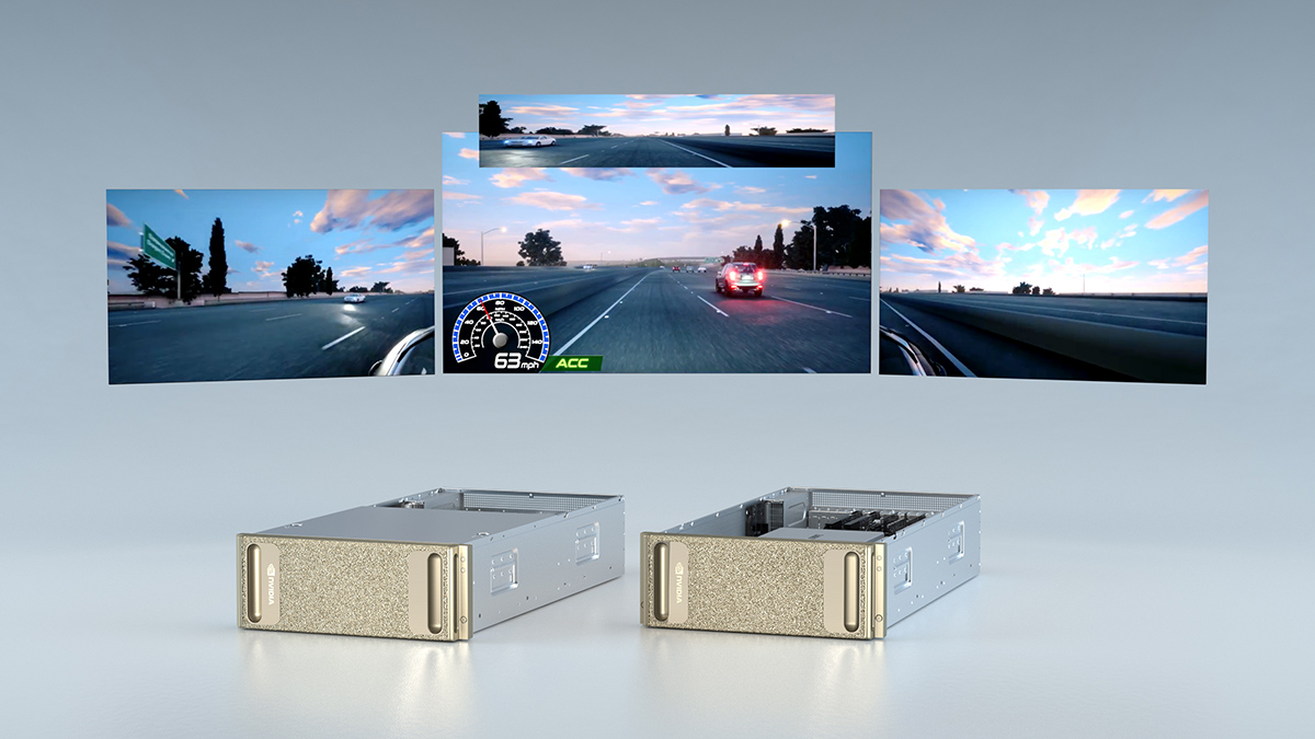

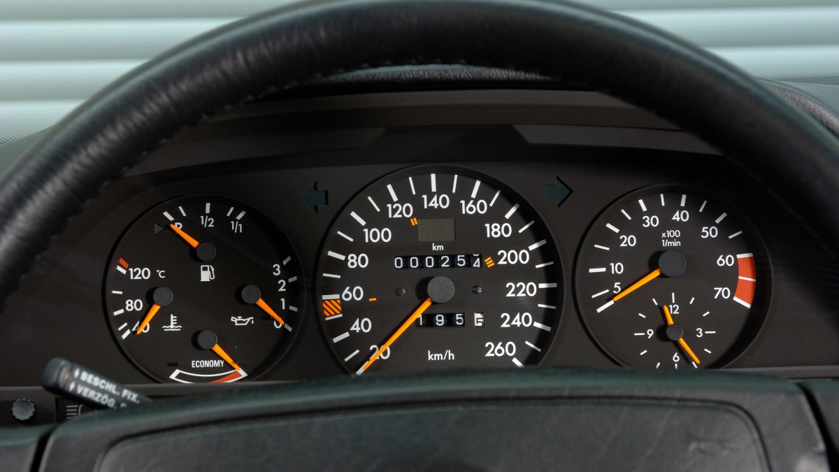
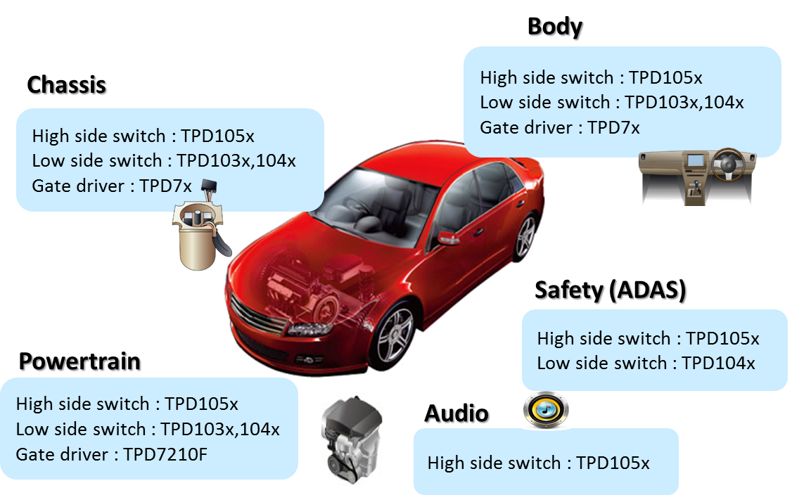

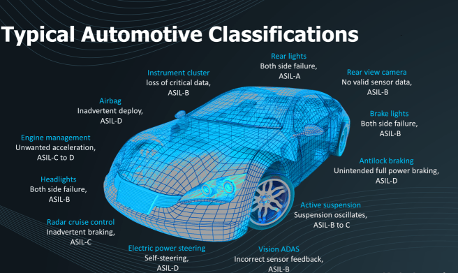
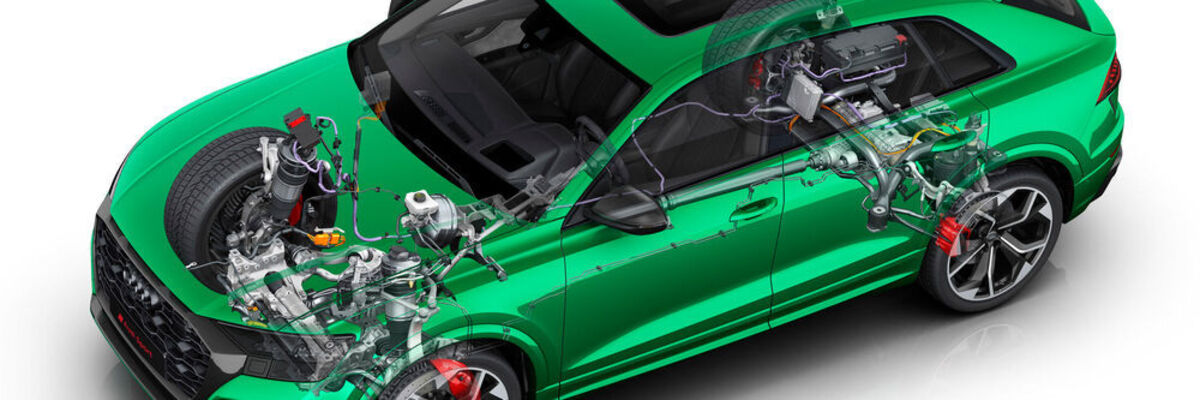


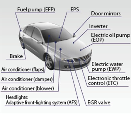


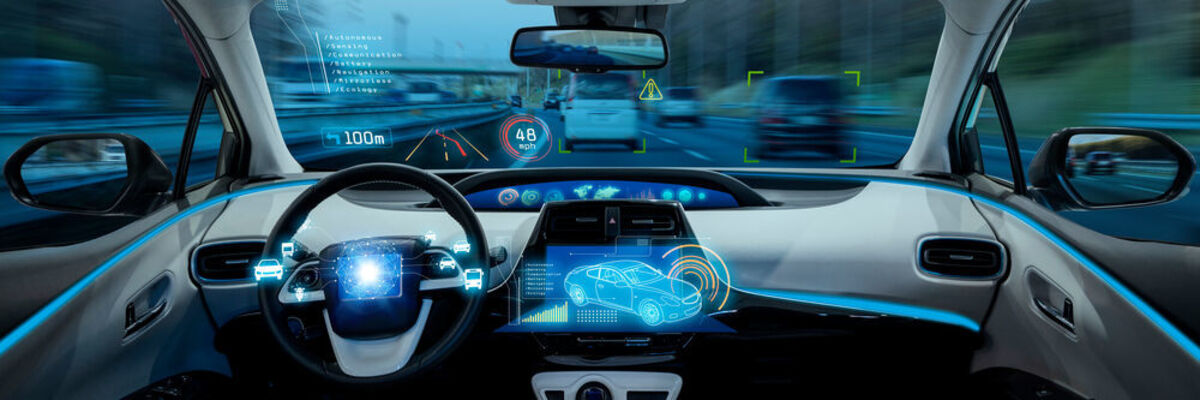
![The resulting circle diagram in the documentation of a measurement provides TE engineers with valuable information on how well an antenna receives a signal depending on the direction of irradiation in the real installation situation. It shows the "antenna gain" (G), the instantaneous value of the field strength measured at the antenna output in [dBµV].](https://cdn1.vogel.de/unsafe/fit-in/1000x0/images.vogel.de/vogelonline/bdb/1618900/1618943/original.jpg "The resulting circle diagram in the documentation of a measurement provides TE engineers with valuable information on how well an antenna receives a signal depending on the direction of irradiation in the real installation situation. It shows the \"antenna gain\" (G), the instantaneous value of the field strength measured at the antenna output in [dBµV].")


 is an open, transparent and non-proprietary proposal for the entire AV industry.")


:quality(90)/images.vogel.de/vogelonline/bdb/1739400/1739496/original.jpg "Cover_Whitepaper_IC Design for New Mobility")
:quality(90)/images.vogel.de/vogelonline/bdb/1739500/1739517/original.jpg "Cover_Whitepaper_LiDAR")