The scope of Electronics
And
Communication Engineering
( E C E )
Basic Electronics Skills for Robotics

Electronics seem scary, but they really aren't so bad. You don't need to be an electrical engineer to start learning electronics. here is a simplified overview of electronics as is necessary for practical robotics. We will barely be scratching the surface of the science and technology behind electronics.
What Is Electronics Communication ?

Electronics is the science and technology concerned with regulating flow of electricity. Put simply, it lets you move electrons around. While this may seem like a kind of pointless activity, the regulation of electrons has enabled some of the most important innovations of the last century including computers, televisions, rocketships, electric cars, rocketships, video games, smartphones .
Voltage, Current and Watts
Before we can regulate electricity, let us take a very brief moment and talk about what electricity is.
Electricity is basically a form of energy resulting from charged particles. It can exist either as a static charge or dynamically as a current.
We will be exclusively dealing with it as a current. A 'direct current' in fact. You may have heard of DC electricity. In case you have not yet figured it out, the abbreviation DC stands for Direct Current. What this means is that electricity flows in one direction only. Since it only flows in one predictable direction, it is easy to regulate.
There are two ways to measure Direct Current that you should be immediately aware of.
Voltage
symbol: V
Voltage is measured in volts. If you were to think of electricty as a river, volts would be how high the water rises above the river bed (or the depth you could say).
Current
Symbol: A
Current is measured in amperes (or - colloquially - amps). If volts is the water depth, than current is the force with which the water is moving.
Just as it is possible to have a really deep river moving with little force, it is also possible to have a really shallow river moving with a lot of force. Voltage and current need to be considered in relation to one another in order to have an understanding of their combined power. The relationship between voltage and current is measured in Watts (symbol: W). This is an expression of the overall power being exerted. You probably have heard this term before, and should just generally be aware of this. However, it is not a particularly important measurement for what we will be doing in this case .
Batteries

Batteries are special containers which store DC electricity at a set voltage.
The most common types of batteries you will encounter are standard cylindrical dry cell batteries. Most notably these consist of AAA, AA, C, and D batteries.
What is important to know about these batteries, is that even thought they are different sizes, they are all rated at 1.5V (remember - V is the abbreviation for volts).
What changes as they get bigger in size is the amount of power they are capable of producing. A D battery will be able to provide power for much longer than a AAA battery. In other words, a bigger battery can provide more amperes for a longer amount of time than a smaller battery.
Batteries are measured in Amp Hours or Ah. This is basically the measure of how many amperes can be drawn from the battery in an hour. For instance, a 20Ah battery will let you draw 1 ampere for 20 hours. However, if your robot needs 5 amperes, you can run that robot for about 4 hours using the same battery (20Ah / 5A = 4 hours).

It may have by now dawned upon you that 1.5V is not very much. You might be wondering why we don't just use a 9V battery instead? Assuredly a 9V battery is producing more power than a 1.5V battery.
This, in fact, is not true at all. 9V batteries actually are not great in producing power at all. A good way to think of a 9V battery is to imagine 6 really small 1.5V batteries smushed together inside. In fact, if you take a 9V apart, that is essentially what you will find inside. Now, compare that to the size of 6 AA batteries for instance. The 9V batteries are rather tiny by comparison!
9V batteries are nice because they are small and can produce a relatively high voltage when you need it, but they don't offer much current and drain quickly when doing things like powering motors. Thus, they are not great for robotics. That is why we will be using a series of 1.5V batteries.
Series and Parallel

Well then, you may be wondering how you can power anything if batteries are only 1.5V? The answer is rather simple. We connect them in series.
What this means is that we connect them front-to back in a row. So the positive (plus) end of one battery gets connected to the ground (minus) end of the next battery, and so on and so forth. We can then calculate the new voltage simply by adding 1.5V for each battery in the series. So, if you have three 1.5V batteries in series, we would calculate that thus:
1.5V + 1.5V + 1.5V = 4.5V
That's pretty much all there is to it.

As illustrated above, instead of putting batteries in series, we can also wire them side-by-side. This is called parallel. When identical power sources are connected in parallel, the voltage remains the same, but the amount of available current increases. This is useful when you don't have enough current to power your circuit.

For instance, say you had a 9V battery that kept draining too quickly or simply was not able to provide enough power to run your device. You could solve this by putting 6 AA batteries in series. However, for argument's sake, let's say your project does not have enough room to do this. You could also wire two 9V batteries in parallel. By doing this, you are essentially doubling the available current.
Keep in mind, this will only work if the batteries are the exact same voltage and should be avoided if possible. Without the proper protection circuit, fluctuation in voltage between the batteries will force them to try to charge one another, decreasing their lifespan.
Battery Holders

There are two notable things to say about battery holders. Foremost, battery holders allow you to easily connect batteries to your circuit.

Secondly, they connect multiple batteries together in series. So you could count the number of cells it holds and multiply it by 1.5 to calculate the voltage of the battery holder. For instance a battery holder with 6 cells provides 9V (1.5 x 6 = 9).
The Multimeter

A multimeter is a tool used for a wide range of electronics related measurements. Or you could say they could meter multiple measurements... multi-meter... painfully obvious - right?
A typical multimeter will measure voltage, current, resistance, and continuity. More advanced multimeters will also measure a host of other things that are not important to get into at this junction.


Another thing you can measure with a multimeter is continuity (pictured left). This is simply a test to determine if electricity can flow freely between two points. In other words, when you touch the two probes to something, you are checking if there is continuous path of conductivity. This can allow you to check whether something is conductive or not. It is also very important for testing to make sure solder connections are correct, and the electricity can flow freely.
The other very important thing we can measure with a multimeter is resistance (pictured right). Resistance is the measure to which a component resists the flow of electricity within a circuit. In other words, something with resistance makes it harder for electricity to flow and converts the electrical energy to something else. It is extremely useful to be able to measure how much resistance a component provides.

To set up the multimeter, plug the black probe into the ground / common port. Plug the red probe into the voltage terminal. It's now all set up.
Using the Multimeter

To use the multimeter simply turn the dial to the electrical property you would like to measure.
Sometimes meters have ranges within the property you are measuring. For instance, you can measure in the millivolt range, or the volts range. Turn the dial to the range you intend to get results in. For instance, if you are expecting a measurement of 5V you want to set the dial to select the option closest to that number.
For argument's sake, let's say we are measuring a 3 X AA battery pack. Touch the red probe to the positive terminal (or red wire) of the thing you are measuring and the black probe to the ground terminal (or black wire) of the thing that you intend to measure.
It should return a constant positive voltage reading. You may have been expecting a perfect 4.5V and gotten a number slightly above or below this. This is normal. Batteries are not regulated and the amount of charge they can provide fluctuates. Particularly, as you use up a battery, the amount of voltage they will be able to provide will drop significantly.

You can also measure resistance by turning the dial to measure ohms (that Greek symbol) on the meter, and putting something that provides resistance - like a resistor - between the probes. Like voltage, resistors can fluctuate a little. For instance, this 100K resistor gives us a reading of 99.7K, which isn't too bad really. It can fluctuate more.
You can test continuity by turning the dial to the symbol that looks like a fast forward symbol on a cassette player (this is actually a diode symbol). Touch one end of the wire to the black probe and the other end to the red probe. When you touch the red probe, the reading on the meter should go from 1 to 0. On most meters, it will also make a beeping sound to indicate electricity can flow.
Lastly, there is the matter of measuring current. While current is a simple principle, is a little bit tricky to measure and we won't be going over it in this class. It will take a lot of time to go over, and you really won't use this too often as a beginner.
Voltage and Ground

If you reverse the probes of the multimeter you will notice that the meter will give you a negative voltage reading. The reason for this is that DC electricity has a positive voltage and a ground voltage.
You can determine a voltage by subtracting the voltage at the red probe (presumably positive) from the voltage at the black probe (presumably ground). So, if when power and voltage are read correctly the formula is:
4.5 - 0 = 4.5
However, when you touch the red wire to ground and the black wire to the positive voltage, your formula actually becomes:
0 - 4.5 = -4.5
The reason for this is that DC electricity has a polarity where one side is always a positive voltage, and one side is not. When you measure the electricity backwards, you get a backwards reading. Thus, if you get a negative voltage reading, you are measuring backwards! Reverse your probes.
Anyhow...
Power always flows between the power source (positive voltage) and ground.
In order for an electrical circuit to operate, there needs to be a path that the electricity can flow between. In fact, given the option of mutiple paths, electricity will always travel the path of least resistance to ground. What this means is that electricity will always take the shortest path that offers the least amount of obstacles. Every electronic component that creates resistance in a circuit is basically an obstacle to the flow of electricity.
Upon hearing this, you may think then that you should provide electricity with the easiest path to ground by removing these obstacles and connecting it directly. However - and this is important to stress - you should NEVER connect your positive voltage source directly to ground. Aside from the fact that removing all obstacles entirely defeats the point of electronics in the first place, this is a very bad idea.

One of the other fundamental rules of electronics is that power must be used. If you connect power and ground directly together, there will be a lot of energy that has no way of expending itself. Your circuit will then try to release this unusued energy in highly antisocial ways. Basically, the energy will turn into heat. However, having nothing in particular to warm, either your power source or wire will start to dramatically heat up. This can potentially result in a damaged power supply, melted wire, or potentially a fire.
Another name of this phenomena is a "short circuit." You likely have heard this term before.
Basically, watch your power and ground connections carefully to prevent them from crossing. Don't release the "magic smoke."
Circuits

A circuit is basically a closed conductive loop in which electricity can flow freely. Basically, a circuit is a bunch of things connected together in either series or parallel that enables electricity to flow between power to ground. This can be as simple as a battery source and a light bulb, or as complex as the controller board for a servo motor. In fact, let's take a closer look at the servo motor's circuit board.

Remove the screws in the back of a continuous rotation servo motor and lift the lid. Set the screws aside for later.

Inside the servo you will find a circuit board that consists of a series of electrical components that have been soldered together to form a circuit. These tiny little parts are arranged in such a way that lets a microcontroller communicate with the servo and control the motor. Don't worry about how. Right now we are simply concerned with the fact that this arrangement of odds and ends regulates electricity in such a way to perform complex tasks.
The Soldering Iron

In order for all of the components on the servo's circuit board to be attached, they needed to be soldered. Soldering is a means of both fusing together two metal objects, and creating an electrical connection.
Unsurprisingly, the tool used for soldering is called a soldering iron.
It may seem intimidating, but a basic soldering iron is actually a rather crude device. It largely consists of a hollow metal tube with an electric heating coil inside. There is a pointy metal tip at one for melting solder, and a heavily insulated handle at the other end to keep your hand from getting burned. There is not too much more to it than that. Fancier soldering irons have fancy-schmancy temperature controls, which really are not remarkably important for what we are doing.

The correct way to hold a soldering iron is like a pencil. All you need to do is hold the insulated rubber handle as though you are holding a writing implement. This will give you a fair amount of dexterity for moving the tip around.
Keep in mind that the uninsulated metal tube gets as hot as the inside of an oven. Whatever you do, never grip the soldering iron from the metal part!
I once saw someone absent-mindedly grab the heated metal tube. It was not pretty! They had to go to the Emergency Room and have their hand treated for extensive burns. You wouldn't want to go to the Emergency Room and have your hand treated for extensive burns, so pay attention to what you are doing!

On a side note, I prefer soldering by a different method which I call the "gorilla technique," which is a bit like holding a spoon. Even though this technique is crude and ape-like, it is - in my opinion - a highly effective way of using it. Simply make a fist around the insulated handle, as though you are holding a sword. Next, rotate your wrist sideways to begin soldering.
Feel free to try it out and use the method that is most comfortable for you. However, should you choose to solder like a gorilla, be prepared for everyone and their mother to tell you that you are doing it wrong.
Preparing the Iron

Before you start soldering your heart out, you will want to 'tin the tip.' What this basically entails is coating the top with an even coat of solder.
Simply plug in the soldering iron and wait a few minutes for it to heat up.
Melt solder evenly around the tip of the soldering iron until there is a nice even silver coat.
Cleaning the Iron
After you tin the tip, you will want to quickly clean the tip.Don't worry. This is easy.
Drag the tip of the soldering iron across a brass cleaning pad two or three times until it looks silver and clean-ish.
Finally, place the soldering iron to rest on its stand, or, should you have a fancier one, in it's holder.
Desoldering

you're rip, roaring, and ready to go.
However, we're going to do things a little backwards. We are going to learn to desolder (remove solder from a circuit) before we learn to solder.
There are a number of different desoldering techniques. We will be using desoldering braid, and ignoring all of the others.

Desoldering braid is basically a strip of tightly woven thin copper mesh that solder bonds well to. When solder is melted, it basically flows from wherever it is at, and gets caught up in the mesh.
To use it, place the desoldering braid atop whatever terminal on a circuit board you are trying to desolder. In our case, we are hoping to desolder the motor. Thus, locate the motor terminals on the circuit board. These are easy to spot because they are the large terminals to the left and right of the motor. In most cases, you can visibly see they are attached to the motor.

Once the desoldering braid is in place, place the soldering iron on top of it and firmly press down. The desoldering braid should now be sandwiched between the soldering iron and the terminal you are trying to desolder.

Typically, in about 10-20 seconds you will feel the solder begin to melt. Continue to hold the soldering iron there for about 5 more seconds. Once it feels like the solder has stopped melting, quickly move away both the soldering iron and the desoldering braid. Be careful not to touch the desoldering braid with your hands as it is likely very hot. Lift it by it's container.
If all goes well, you should now see a pool of solder on the desoldering braid, and the solder removed the circuit board. If not all the solder has been removed from the circuit board, repeat the process with a fresh section of desoldering braid until the terminal is detached.

This may take some practice to get right. Fortunately there is a second terminal to desolder before you can free the board from the motor. Desolder the other motor terminal as well in the same fashion.

Once both terminals are desoldered, gently remove the circuit board.
Also, keep in mind that soldering is going to seem like a piece of cake compared to this.
All About Wire ?

Before we get to soldering, let us take a moment and discuss wire. You may be wondering what there is to say about wire? Well - a lot!

In electronics, the wire we will be dealing with is insulated. This means that there is a metal core inside of a rubber or plastic insulator. This allows electricity to flow, but prevents the wires from shorting if they were to touch (because they are insulated).

There are two types of metal cores we will be dealing with.
Solid core wire has a single peice of metal inside the insulation. This wire is good for electronic circuit boards or connecting components to a microcontroller because this type of wire can easily plug into the board's sockets. This type of wire keeps its shape when bent, but also it more prone to break if flexed too often.
Stranded core wire has a braid of thin metal strands inside. This wire is better for connecting to components which are handled a lot or move around (such as connecting to motors on a robot arm). This type of wire does not easily plug into a microcontroller's sockets, making it annoying for prototyping. However, it is very flexible and can be bent a lot without snapping.

The thickness of wire is measured in gauges. The thicker the gauge, the more current it can handle. In America, gauge is measured in AWG.
We will largely be dealing with wire in the 20 AWG to 22 AWG range.

Even though all wire essentially works the same regardless of color, there is a generally agreed upon color-coding system for wire when dealing with DC electronics.
Red indicates a power wire.
Black indicates a ground wire.
Green (or any color not red or black) indicates a signal or data wire.
While you are probably thinking we've exhausted all that there is say about wire, you would be wrong. However, there is still a lot more ground to cover and we should probably continue this wire discussion another day. We still have a lot left to do, like soldering wires to the motor terminals inside of the servo.
Soldering

Using the servo motor we desoldered earlier, let's now solder new wires onto the motor!
To do this, strip some of the insulation from the end of 6" piece of red wire, and hook it around the motor terminal with a little red dot next to it. The red indcates that this is the motor's positive terminal.


Next, use the soldering iron to heat up the terminal and the end of the wire. While doing this, push the solder into the tip of the soldering iron. All goes well, you should get a nice shiny solder connection between the two. This might take some practice to get right.
Let the solder cool and you're done.
Repeat this process with a 6" piece of black wire and the motor's ground terminal.

When you are done, use your diagonal cutting pliers to trim away any excess leads sticking off of the soldered connection. The less conductive material you have exposed, the better. This will also help put the lid back on.


Take both wires and tie a knot such that the knot extends past the servo casing once tightened. The knot should be put on the inside of the servo assembly when you close the lid. This will prevent the wires from getting pulled out and keep the solder connections from being broken should something catch onto the wire and pull.

Finally, close the servo back up using its screws.
Test Your Work
Take a red jumper cable and connect one end to the red wire on a 4 X AA battery holder, and the other the red wire on the motor.
Take a black jumper cable and connect together the black wire from the battery holder to the black wire from the motor.
All goes well, the motor should spin clockwise.
To reverse the motor direction, simply flip the connections by attaching the red jumper cable to the motor's black wire and the black jumper cable to the motor's red wire.
_________________________________________________________________________________
Motors and Motion

As things
currently stand, by and large, robotic motion is created by motors. By
employing motors in creative ways, an unimaginable amount of robotic
automation is possible. It is therefore important to begin to learn
about motors if you want to build robots of your own. There are a lot of
different types of motors out there in the world. This is by no means
an exhaustive guide, but a crash course in using motors. While this is
just an initial general overview, we will continue to cover motors more
thoroughly as we progress through the class and our skills become more
advanced.
An
electric motor is a machine that transforms electrical energy into
mechanical energy. Put another way, when this machine is powered by
electricity, it moves (typically by rotating). 
If you were to take apart a DC motor, it would look very complicated, but it is actually a fairly basic device.
When power is applied to the motor at their outer terminals, it travels across the brushes to the commutator. The brushes got their name because they literally brush across the commutator as it spins freely between them.
The commutator is made out of separate pieces of conductive material attached around the motor's shaft. Each piece of the commutator is attached to a different wire in the motor's winding. As the shaft spins, and the brushes rub against them, they make and break electrical contact with each one and power the different windings.
The windings are basically inductor coils.
When the windings are powered, they create a magnetic field through the rotor it is wound around. The field that is created in the rotor reacts to the magnetic field of the magnets which are permanently fixed in place inside of the stator (metal enclosure). These competing magnetic forces causes the rotor, which is attached to the motor shaft, to spin into alignment as it is repelled / attracted to the fixed magnets.
If you understand how magnets work, you would know that once the fields are aligned, the rotor should stop spinning. However, as it spins, the electrical connection to the winding being energized is broken, and the commutator powers up the next winding, causing this next one to spin once more into place. As this new one spins, the connection is broken again, and the next winding is powered up continuing the cycle. This sequence will continue indefinitely so long as the motor is powered.
Since the rotor is attached to the the shaft, this explains why the motor's shaft rotates when electricity is applied. For its part, the shaft is held in place by a bearing in the front (and sometimes the back) of the stator (enclosure).
There are three common types of motors that you will typically encounter in robotics. This is not to say these are the only types of motors that exist, but they are the motors you are most likely to be working with.

DC motors spin freely when powered by a DC current. These motors spin freely when powered and have no precise positioning. They are best as robotic drive motors. You can typically identify a DC motor because it looks like a round metal tube with a shaft in the center and two terminals in the back. These motors come in a wide range of different sizes and operating voltages.

Stepper motors have two or more separate coils that need to be powered in a particular sequence. On account of this, the shaft moves in small "step" increments as the power is cycled between coils. These motors are good for precise positioning and speed control, particularly when you need a motor that can spin spin 360 degrees. You can typically identify a stepper motor because it has a box like shape and/or has 4 or more wires coming out of its side. The most common type of stepper motor is a bipolar motor, which has two coils, and four wires (two for each wire). These are typically the type you will encounter.

Servo motors are specialized DC gear motors with a built in control board that requires a signal from a microcontroller. Most servos have limited rotation and are capable of being directed to move to a really precise position. However, there are continuous rotation servos which cannot move to exact position, but can be programmed in terms of speed. You can identify a servo motor because it is box-like and has a gear-like thing attached to its shaft.
There is an entire servo lesson coming up where we will discuss this type of motor in more depth.
There are some factors to consider when selecting a motor.

As a general rule, the larger of a motor you choose, the more voltage and current it can handle. This is important because there is a correlation between voltage and speed, and another between current and torque.

Put simply, the more voltage that is applied to a motor, the faster it spins.
However, like all electronics, motors have an optimal voltage range and should never exceed its maximum voltage. That means DC motors also have a maximum speed (at their maximum operating voltage).

For those unfamiliar, torque is the amount of rotational force a motor can apply. Like speed, motors also have a maximum amount of torque that they can produce before they stall (or stop spinning). As the motor encounters increasing resistance and gets closer and closer to stalling, the amount of current it draws increases. The absolute amount of current a motor can draw when it encounters so much resistance that it stops spinning is called its stall current.
The stall current is important because it will indicate a motor's potential power. The higher this number is, the more potential power the motor has. Although, when your robot's motor is spinning freely and not encountering much resistance, it will not draw nearly as much current.
As a general rule, the larger of a motor you choose, the more voltage and current it can handle. This is important because there is a correlation between voltage and speed, and another between current and torque.
Put simply, the more voltage that is applied to a motor, the faster it spins.
However, like all electronics, motors have an optimal voltage range and should never exceed its maximum voltage. That means DC motors also have a maximum speed (at their maximum operating voltage).
For those unfamiliar, torque is the amount of rotational force a motor can apply. Like speed, motors also have a maximum amount of torque that they can produce before they stall (or stop spinning). As the motor encounters increasing resistance and gets closer and closer to stalling, the amount of current it draws increases. The absolute amount of current a motor can draw when it encounters so much resistance that it stops spinning is called its stall current.
The stall current is important because it will indicate a motor's potential power. The higher this number is, the more potential power the motor has. Although, when your robot's motor is spinning freely and not encountering much resistance, it will not draw nearly as much current.

Unlike the motor's voltage supply
which can be varied by adjusting the voltage within its operating range,
the options for adjusting torque are not so easy. You can simply get a
bigger and beefier motor to solve this problem, or you can use a
gearbox.

A gearbox is a collection of gears arranged in such a way that it translates the speed and torque of a motor to either increase or decrease (depending on the arrangement). The motor's shaft will be attached to one end of the gearbox, and as the motor spins, the rotation will get translated to a different speed at the output shaft of the gearbox.
As a rule, the faster the motor spins, the less torque it provides. Slower gearboxes provide more torque than faster ones, and vice versa.

It is rare that you would have to build your own gearbox. Many motors come assembled with a gearbox already attached in a host of different configurations. Geared motors are a great way to get a lot of power into a small package, or slow a DC motor down without relying on a motor controller to do all the work.
You can usually identify a geared motor because it looks like a normal motor, but with a bigger cylinder on the end. Also, the shaft is often off-centered.
A gearbox is a collection of gears arranged in such a way that it translates the speed and torque of a motor to either increase or decrease (depending on the arrangement). The motor's shaft will be attached to one end of the gearbox, and as the motor spins, the rotation will get translated to a different speed at the output shaft of the gearbox.
As a rule, the faster the motor spins, the less torque it provides. Slower gearboxes provide more torque than faster ones, and vice versa.
It is rare that you would have to build your own gearbox. Many motors come assembled with a gearbox already attached in a host of different configurations. Geared motors are a great way to get a lot of power into a small package, or slow a DC motor down without relying on a motor controller to do all the work.
You can usually identify a geared motor because it looks like a normal motor, but with a bigger cylinder on the end. Also, the shaft is often off-centered.

By attaching the shaft of the
motor to different mechanical systems, you can achieve different types
of motion. These assemblies can ultimately be combined to create
advanced electromechanical assemblies that solve different tasks. Albeit
not quite robotic, the above tape player mechanism illustrates this.
Follows are the primary forms of motion you will achieve from a standard mechanism.

Rotary motion is the easiest to achieve because the shaft of the motor is already rotating. Typically, rotary systems involve increasing or decreasing the motor's speed of rotation. As mentioned, this also changes the torque of the system in relation. The type of rotary mechanism you will typically encounter involves gears or pulleys.

Linear motion translates rotational motion into motion across a flat plane. Classic examples of this include conveyor belts and tank tracks. This systems uses two or more rotary cogs or pulleys (one connected to the drive shaft, and one free spinning) to pull a flat track around them. The further the distance between these cogs, the longer the track will be. As the track gets pulled around the cogs, it moves in direction across a flat plane.

Reciprocating motion is a motion that moves back and forth in a linear fashion. This type of motion is often used to move a piston or in an automated door lock. There are many different ways to mechanically achieve reciprocating motion. Common approaches involve using a yoke (as pictured), a cam, or linkages.

Oscillating motion involves any part that moves back and forth along an arc. The most classic example of this motion is a metronome. Like most of the other movements, oscillating motion can be created by using a range of different mechanisms, including linkages. Most typically it just requires one part one a fixed pivot being pushed back and forth by some other part.
Follows are the primary forms of motion you will achieve from a standard mechanism.
Rotary motion is the easiest to achieve because the shaft of the motor is already rotating. Typically, rotary systems involve increasing or decreasing the motor's speed of rotation. As mentioned, this also changes the torque of the system in relation. The type of rotary mechanism you will typically encounter involves gears or pulleys.
Linear motion translates rotational motion into motion across a flat plane. Classic examples of this include conveyor belts and tank tracks. This systems uses two or more rotary cogs or pulleys (one connected to the drive shaft, and one free spinning) to pull a flat track around them. The further the distance between these cogs, the longer the track will be. As the track gets pulled around the cogs, it moves in direction across a flat plane.
Reciprocating motion is a motion that moves back and forth in a linear fashion. This type of motion is often used to move a piston or in an automated door lock. There are many different ways to mechanically achieve reciprocating motion. Common approaches involve using a yoke (as pictured), a cam, or linkages.
Oscillating motion involves any part that moves back and forth along an arc. The most classic example of this motion is a metronome. Like most of the other movements, oscillating motion can be created by using a range of different mechanisms, including linkages. Most typically it just requires one part one a fixed pivot being pushed back and forth by some other part.
In
order to achieve the different types of motion, you need to use
mechanical parts. There are more mechanisms in this world than I could
possibly go over, but here are some common ones you may encounter in
robotics.

The simplest mechanism that you can attach is an off-centered weight on a rotary shaft. This will cause the motor to vibrate. These are most often used in vibrobots to create complex motion. This type of motion is the fastest path to get to gratification, but is also the most difficult to steer. The robot will tend to veer left or right, depending on which direction the motor is spinning, but it's movements will largely be arbitrary.

Pulleys are a type of rotational mechanism that can be used to change speed, torque, or - in some cases - motor direction. The nice thing about using pulleys is that they are friction based, so if the drive shaft they are attached to seizes up or gets stuck, the belts will slip and the motor will continue to spin. This puts less pressure on both the motor and electronic system from the motor having to work harder and draw more current as it gets closer to stalling. However, the bad thing about pulleys is that they can slip, so they are not as precise as other mechanisms. They are thus best suited for drive systems where motor precision isn't quite as important and the drive shaft is most likely to encounter resistance and stall.

Another type of common rotational mechanism are gears. Gears function in many of the same way pulleys do. However, unlike pulleys, gears can also come in other shapes such as a "rack" configuration like in the 3D printed robot above, and be used to create linear motion. Gears also don't rely on friction to rotate the shafts, but rather have a series of interlocking meshed teeth. This makes them more precise since the meshing teeth ensure uniform and predictable amounts of rotation from one shaft to the next.
On account of the paired and meshing teeth, gears also require a very precise alignment. If they are too far apart, the gears will skip or wear down faster, and if they are too close together the gears will apply too much pressure and seize. Speaking of which, gear systems don't like to be stalled. This translates a lot of force to the teeth of the gear which are usually small and brittle. This can cause a tooth on the gear to break, which could lead to imprecision, or failure of the entire mechanical system. You can tell a geared system is broken because it is entirely seized up or is making horrible grinding noises.

A simple way to translate rotary motion to reciprocating, linear, or oscillating motion is to use a cam. A cam is just a lever arm which spins off-center from the shaft. The most common type of cam is oval shaped. However, cams can come in a number of different shapes and sizes, from rectangular shaped to heart shaped. Cams just push on things and can serve all kinds of purposes in mechanical systems. In this instance, the two cams are both lifting and propelling the robot forward as they are rotated by the servos.

Linkages can be used to create reciprocating and oscillating motion. All that a linkage happens to be is simply a rigid bar with holes in it for pivots. In a linkage system, some of them are constrained to other linkages, and others are fixed to the surface upon which the motor is rotating. By creating a combination of free and fixed pivots, the linkages are able to create a multitude of complex motions.

Another common method to translate motion is to use tracks. Aside from making any robot look like a tank, this form of conversion creates linear motion. One of the benefits of a tracked vehicle is that its method of locomotion has much more surface area than a wheel. This enables it to have more friction with the ground, which is essential for climbing over uneven surfaces and obstacles. The fact that tracks inherently have a little bit of give across their length also doesn't hurt with this either since they are able to conform to slightly uneven planes.
The simplest mechanism that you can attach is an off-centered weight on a rotary shaft. This will cause the motor to vibrate. These are most often used in vibrobots to create complex motion. This type of motion is the fastest path to get to gratification, but is also the most difficult to steer. The robot will tend to veer left or right, depending on which direction the motor is spinning, but it's movements will largely be arbitrary.
Pulleys are a type of rotational mechanism that can be used to change speed, torque, or - in some cases - motor direction. The nice thing about using pulleys is that they are friction based, so if the drive shaft they are attached to seizes up or gets stuck, the belts will slip and the motor will continue to spin. This puts less pressure on both the motor and electronic system from the motor having to work harder and draw more current as it gets closer to stalling. However, the bad thing about pulleys is that they can slip, so they are not as precise as other mechanisms. They are thus best suited for drive systems where motor precision isn't quite as important and the drive shaft is most likely to encounter resistance and stall.
Another type of common rotational mechanism are gears. Gears function in many of the same way pulleys do. However, unlike pulleys, gears can also come in other shapes such as a "rack" configuration like in the 3D printed robot above, and be used to create linear motion. Gears also don't rely on friction to rotate the shafts, but rather have a series of interlocking meshed teeth. This makes them more precise since the meshing teeth ensure uniform and predictable amounts of rotation from one shaft to the next.
On account of the paired and meshing teeth, gears also require a very precise alignment. If they are too far apart, the gears will skip or wear down faster, and if they are too close together the gears will apply too much pressure and seize. Speaking of which, gear systems don't like to be stalled. This translates a lot of force to the teeth of the gear which are usually small and brittle. This can cause a tooth on the gear to break, which could lead to imprecision, or failure of the entire mechanical system. You can tell a geared system is broken because it is entirely seized up or is making horrible grinding noises.
A simple way to translate rotary motion to reciprocating, linear, or oscillating motion is to use a cam. A cam is just a lever arm which spins off-center from the shaft. The most common type of cam is oval shaped. However, cams can come in a number of different shapes and sizes, from rectangular shaped to heart shaped. Cams just push on things and can serve all kinds of purposes in mechanical systems. In this instance, the two cams are both lifting and propelling the robot forward as they are rotated by the servos.
Linkages can be used to create reciprocating and oscillating motion. All that a linkage happens to be is simply a rigid bar with holes in it for pivots. In a linkage system, some of them are constrained to other linkages, and others are fixed to the surface upon which the motor is rotating. By creating a combination of free and fixed pivots, the linkages are able to create a multitude of complex motions.
Another common method to translate motion is to use tracks. Aside from making any robot look like a tank, this form of conversion creates linear motion. One of the benefits of a tracked vehicle is that its method of locomotion has much more surface area than a wheel. This enables it to have more friction with the ground, which is essential for climbing over uneven surfaces and obstacles. The fact that tracks inherently have a little bit of give across their length also doesn't hurt with this either since they are able to conform to slightly uneven planes.
Let's now take a moment to discuss some practical concerns.

To power a DC motor, all you need to do is connect a positive voltage (within its power rating) to one terminal on the motor, and ground to the other terminal.

To reverse the direction of the DC motor, simply reverse the wires connected to each terminal. The reason the motor spins backwards when you do this is that the magnetic poles created within the windings is reversed when you power it the opposite way. This forces the rotor to spin the opposite way to align with the fixed magnets inside the stator (motor enclosure).
To power a DC motor, all you need to do is connect a positive voltage (within its power rating) to one terminal on the motor, and ground to the other terminal.
To reverse the direction of the DC motor, simply reverse the wires connected to each terminal. The reason the motor spins backwards when you do this is that the magnetic poles created within the windings is reversed when you power it the opposite way. This forces the rotor to spin the opposite way to align with the fixed magnets inside the stator (motor enclosure).
_______________________________________________________________________________
Robot Brains

To make
decisions, a robot uses a computer or microcontroller. For those
unfamiliar, a microcontroller is basically an electronic component which
can do three things. It can interpret inputs from the physical world,
process this information, and control output devices in the physical
world. In a basic sense, a microcontroller can read sensors, make
decisions, and control lights, speakers, and motors.
By being able to both sense and respond to the world, you can create a feedback loop between the output and the input. In other words, you can create robots and devices which are truly interactive. Another way to think about this is that the robots can pay attention to what is happening around them, make decisions using the Arduino, and then respond meaningfully to it. In this way, they behave a bit like most other sentient creatures.
By being able to both sense and respond to the world, you can create a feedback loop between the output and the input. In other words, you can create robots and devices which are truly interactive. Another way to think about this is that the robots can pay attention to what is happening around them, make decisions using the Arduino, and then respond meaningfully to it. In this way, they behave a bit like most other sentient creatures.
The Arduino

The Arduino is a very common type
of microcontroller. What sets the Arduino apart from other
microcontrollers is that is is easy to use, well documented, and has a
vast online community of people using it. This means that no matter what
may go wrong, you can likely find a documented solution online or
someone willing to help you. This is extremely beneficial when getting
started.
There are a number of different types of Arduinos, but for this class we will be using an Arduino Uno. This is currently the most ubiquitous version of Arduino microcontrollers. By the time this lesson is over, you will have a brief understanding of how to use the board, but you will by no means be an expert.
While the Arduino has a lot of features, there are a few you have to pay attention to. There is a USB port which is used for programming. There is a power socket that is used for powering the Arduino when not connected to your computer. There are also two rows of female sockets along the edge of the board. Each one of these little holes connects to something different on the board, and performs a different function. They should all be labeled fairly well to indicate what they are.
If and when you get confused, you can find a much more in-depth overview by checking out the Arduino Class.
Plug It In.

To power up the board simply
connect it to your computer with a USB-A to USB-B cable. This is
basically a standard USB cable that something like a computer printer
would use.
Programming the Arduino

To program the Arduino we will be
using the Arduino IDE (integrated development environment). The most
current version of the software can be downloaded for free from the Arduino site or used directly on the internet (soon).
A Note About Programming
The most important thing to know
about programming is to fake it untill you make it. Basically, you don't
actually need to know how to program to work with code. There is a ton
of example code already out there. You just need to understand its basic
structure. Once you got this, it is just a matter of finding and
tweaking code which already exists. If you just stick with this
approach, keep an open mind, and a fearless spirit, eventually you will
learn to program for real-like.
However, it is not entirely a free-for-all. There are a few things you need to understand. Please bear with me while I drop some very basic coding knowledge on you. BAM!
However, it is not entirely a free-for-all. There are a few things you need to understand. Please bear with me while I drop some very basic coding knowledge on you. BAM!
Syntax
Every programming language has a
syntax for how the code needs to be formatted. That is basically the
equivalent of knowing proper grammar.
For instance, most expressions in programming end with a semicolon -
like so; This is a bit like writing a period at the end of the sentence.
If you write an essay without periods you will confuse the heck out of
the reader. Likewise, if you write an Arduino program without syntax,
you will confuse the heck out of the compiler. The compiler interprets
the code and is a bit like the reader of an essay in our analogy.
If you are ever getting strange errors and can't tell why, chances are you have broken one of the rules of syntax (i.e. formatting).
If you are ever getting strange errors and can't tell why, chances are you have broken one of the rules of syntax (i.e. formatting).
Code Expressions
When reading and writing code you
will encounter some basic building blocks just like you would in any
other language. For instance, English has nouns, adjectives, and verbs.
These components are then structured into sentences. Programming in turn
has constants, variables and operators. These are then structured into
functions.
Here are some basic definitions of common programming components:
Constants are terms which are defined once and do not change.
Variables are terms which are placeholders for other values and can change.
Operators are terms which perform an action, which is typically some form of math or logical comparison between values.
Functions are a structured collection of constants, operators and variables. Every time a function is called, it reads through and executes the same specific action routine.
Program Structure
Once you have mastered the components
of English grammar and have begun writing sentences, the next logical
step is to write a composition such as an essay. Just as an essay has a
structure with an opening paragraph, body text, and a closing paragraph,
so does an Arduino program. However, an Arduino program's structure is a
little bit different.
A typical program is laid out as follows:
The compiler typically reads from left to right from one line to the next. Well - for the most part. There are a few key differences from the way that a normal person that are crucial to understand.
A good way to think about a computer program is a bit like a choose your own adventure story. The compiler reads the story like it would any other, but when the compiler reads a function, instead of reading the next line, it jumps to where that function lives and reads it line by line instead. When it is done reading the function, it goes back to the next line in the code from where it left off. Also, functions can have other functions nested within them. So, a function, can lead to another function, to yet another function, before going back to the main routine.
If that in and of itself were not confusing, the program all reads down the page - to a point! And this is important to remember... When the compiler gets to the main loop(), whatever is contained within this loop is repeated over and over and over and over until the Arduino runs out of power. The main loop() is the endlessly repetative place where the meat of the code should live. Whatever you are trying to accomplish should exist in the main loop().
All of this is likely very confusing and foreign to you. That's okay. Learning the Arduino programming language is a bit like learning any language. It takes time to get the hang of it, and even then it takes a long time to be truly fluent.
To learn more about programming, a good place to start is Codecadamy.
Run a Program

Running a program on the Arduino is dead simple.
To begin, you need to specify the type of board you are using. That is easy, select the "Arduino/Genuino Uno" option.

You also eneds to specify the port where the Arduino is found. That is a little bit trickier, but not too hard. Just select the option that looks like "/dev/cu.usbmodem [random numbers]"

Open the Blink example from the Example 01.Basics menu. Then, find the upload button (this looks like right-pointing arrow) and press it. If everything is configured correctly, it should cause the LED on the Arduino board to blink steadily.
Try changing the number value within the delay functions and reupload the code. Notice that it changes the rate at which it blinks.
Now that you have got this down, let's try blinking an external LED not soldered directly to the Arduino board.
To begin, you need to specify the type of board you are using. That is easy, select the "Arduino/Genuino Uno" option.
You also eneds to specify the port where the Arduino is found. That is a little bit trickier, but not too hard. Just select the option that looks like "/dev/cu.usbmodem [random numbers]"
Open the Blink example from the Example 01.Basics menu. Then, find the upload button (this looks like right-pointing arrow) and press it. If everything is configured correctly, it should cause the LED on the Arduino board to blink steadily.
Try changing the number value within the delay functions and reupload the code. Notice that it changes the rate at which it blinks.
Now that you have got this down, let's try blinking an external LED not soldered directly to the Arduino board.
All About Breadboards

When you need to prototype a circuit that connects to the Arduino, you should use a breadboard.
Breadboard are meant to make quick non-permananent connections between electronic components. They are covered in tiny socket holes which are connected in rows. The board itself is broken into four sections. There are two inner sections full of short horizontal rows, and two outer sections with longer vertical rows.
The inner sections are typically used for connecting components, and the outer sections are typically used as power bus lines. In other words, you can connect a battery to one of the outer lines and then power components on the inner section by connecting a wire to this section.
In the above graphic you can visually get a sense of how the rows on breadboards are electrically connected. The two inner sections have short horizontal rows repeated down the board. The two outer sections each have two long vertical rows. These are marked in red and blue and are meant to signify a row for power (red) and a row for ground (blue). Not all breadboards are marked with lines like this, but they are all laid out the same way.
For much more information about breadboard's check out this Breadboard Tutorial.
A Quick Note on LEDs

Althought people think of LEDs as
little light bulbs, they are actually quite different. LEDs are a type
of electronic component called a diode. In fact, LED is an abbreviation
for light emitting diode.
There is a lot to say about their unique status as a diode, but for our purposes the only thing that you need to know is that diodes only allow electricity to flow in one direction. They are what you would call 'polarized'. There is one leg that should always be connected to power and one that should be connected to ground. If you connect them backwards, power won't flow.

The leg which is connected to power is called the anode. The leg which is connected to ground is called the cathode. There are three ways to tell apart an LED's anode from its cathode.
1) The leg connected to the anode is typically longer than the one connected to the cathode.
2) The body of the LED typically has a flat spot on the cathode side.
3) If you look inside the LED, the little metal bit connected to the anode lead is much smaller than the cathode.
There is a lot to say about their unique status as a diode, but for our purposes the only thing that you need to know is that diodes only allow electricity to flow in one direction. They are what you would call 'polarized'. There is one leg that should always be connected to power and one that should be connected to ground. If you connect them backwards, power won't flow.
The leg which is connected to power is called the anode. The leg which is connected to ground is called the cathode. There are three ways to tell apart an LED's anode from its cathode.
1) The leg connected to the anode is typically longer than the one connected to the cathode.
2) The body of the LED typically has a flat spot on the cathode side.
3) If you look inside the LED, the little metal bit connected to the anode lead is much smaller than the cathode.
Resistors

Resistors basically add resistance to a circuit. There are many reasons for doing this, but I don't have all day to explain.
Basically, we need a resistor in the circuit we are about to build because an LED offers no resistance. If we connect power through an LED without any resistance, then it is basically the same as creating a short circuit by connecting the power supply to ground. We add a resistor in series to the LED to use up some of the power and prevent a short circuit. If you want to know more, you can learn more about resistors and resistance in the Basic Electronics tutorial.

The only thing we need to know about resistors at this juncture is that even though they roughly look the same, they all have different values. You can tell how much resistance each one offers by reading the resistor codes marked upon them. Resistor codes are read from left to right towards the gold (or silver) band.
To begin, the easiest way to interpret the codes is to use an online graphical resistor calculator. Once you use this enough, you will begin to learn how to interpret them on your own without the calculator.
Basically, we need a resistor in the circuit we are about to build because an LED offers no resistance. If we connect power through an LED without any resistance, then it is basically the same as creating a short circuit by connecting the power supply to ground. We add a resistor in series to the LED to use up some of the power and prevent a short circuit. If you want to know more, you can learn more about resistors and resistance in the Basic Electronics tutorial.
The only thing we need to know about resistors at this juncture is that even though they roughly look the same, they all have different values. You can tell how much resistance each one offers by reading the resistor codes marked upon them. Resistor codes are read from left to right towards the gold (or silver) band.
To begin, the easiest way to interpret the codes is to use an online graphical resistor calculator. Once you use this enough, you will begin to learn how to interpret them on your own without the calculator.
Breadboard a Circuit

Insert an LED into a breadboard. Connect a 150 ohm resistor in series with the LED's cathode.
Using a black solid core wire, connect the opposite end of the resistor (the side not connected to the LED) to ground on the Arduino.
Using a red solid core wire, connect the LED's anode to digital pin 7 on the Arduino.
Using a black solid core wire, connect the opposite end of the resistor (the side not connected to the LED) to ground on the Arduino.
Using a red solid core wire, connect the LED's anode to digital pin 7 on the Arduino.
Blink an External LED

You can blink an external LED by
opening the Blink example code and changing this code and replacing all
the number 13 to the number 7 whenever it shows up. By doing this, you
are simply changing the digital pin that is being pulsed on and off from
13 to 7 in order to match the circuit you built on your breadboard.
Fade an LED

Aside from blinking an LED, we can
also make one fade. To do this we need to use a PWM pin. The PWM pins
are special digital pins on the Arduino that allow for an analog-like
output that simulates an output voltage between 0 and 5V. They are all
labeled with a ~ in front of the pin number.
PWM stands for pulse width modulation. Put simply, PWM is toggling a pin on and off so fast that it gives the appearance of dimming the LED.
A dim LED glowing at 1/4 brightness means that the signal being sent to it is toggled off much more than it is toggled on. For instance, it is turned off 75% of the time and turned on 25% of the time. A brighter LED at 3/4 brightness is receiving a PWM signal that is the opposite. So it would be on 75% of the time and off 25%. The thing is, it is happening so fast, you don't see that it is being turned on and off, but only experience the LED as being slightly dim.
Anyhow, if you want to fade the LED, from the examples menu select:
03.Analog --> Fading
Once done, swap the wire connected from digital pin 7 to digital pin 9, and upload the code to your Arduino.
The LED should now fade in and out.

Once you have mastered blinking
and fading LEDs, you can transfer this knowledge to controlling a motor.
However, you cannot connect a motor directly to the Arduino pin for two
reasons. First, the Arduino pin is only able to provide a little bit of
current, and a motor is a current hog (especially when it starts and
stops). Also, when a motor stops, it produces a current of opposite
polarity to the one it is running at. This current is known to damage
Arduino pins and stop them from working. Thus, building a buffer circuit
is useful.

All you need to control a motor using an Arduino is a 2K resistor, an NPN transistor (TIP120 in this case), and a 1N4001 diode. The 2K resistor works to protect the Arduino pin, the transistor serves as a valve which lets more or less current flow through the motor. This is what turns the motor on and off, and controls its speed.
The diode is used as a buffer. When electricity flows through the motor, the diode does nothing. However, when the motor stops, the reverse current flows across the diode, and back through the motor. This protects the circuit from sudden voltage spikes.
If all of this sounds confusing, you can learn more about these basic components in my Electronics Class.

If you want to turn the motor on and off using the pictured circuit you need to make two more connections. First, connect the external battery pack's ground to the Arduino's ground pin. This is called "sharing ground" and is necessary for the circuit to work. Next, connect pin 13 from the Arduino to the 2K resistor connected to the transistors base. Once this is done, load the Blink example and upload it to the Arduino. Instead of blinking an LED, it will power on and off the motor.

If you want to control the motor's speed, change the wiring to pin 13, and load the fade example to increase and decrease the motor's speed.
It may now have dawned upon you, neither of these solutions will reverse the motor. To make a motor spin backwards, you will need an H-bridge.
All you need to control a motor using an Arduino is a 2K resistor, an NPN transistor (TIP120 in this case), and a 1N4001 diode. The 2K resistor works to protect the Arduino pin, the transistor serves as a valve which lets more or less current flow through the motor. This is what turns the motor on and off, and controls its speed.
The diode is used as a buffer. When electricity flows through the motor, the diode does nothing. However, when the motor stops, the reverse current flows across the diode, and back through the motor. This protects the circuit from sudden voltage spikes.
If all of this sounds confusing, you can learn more about these basic components in my Electronics Class.
If you want to turn the motor on and off using the pictured circuit you need to make two more connections. First, connect the external battery pack's ground to the Arduino's ground pin. This is called "sharing ground" and is necessary for the circuit to work. Next, connect pin 13 from the Arduino to the 2K resistor connected to the transistors base. Once this is done, load the Blink example and upload it to the Arduino. Instead of blinking an LED, it will power on and off the motor.
If you want to control the motor's speed, change the wiring to pin 13, and load the fade example to increase and decrease the motor's speed.
It may now have dawned upon you, neither of these solutions will reverse the motor. To make a motor spin backwards, you will need an H-bridge.

An H-bridge is a circuit that allows a motor's direction to be reversed. More advanced H-bridges - like the kind found inside of servo motors - also allow you to control the speed of the motor.
Essentially, an H-bridge consists of four switches or transistors. In the above example, there is a switch between each pole of the motor and ground. There is also another set of switches between each pole of the motor and power.
When these switches are drawn out in a diagram, they look kind of like an “H”. That is how the circuit gets the name H-bridge.

When the set of switches labeled with “A” is closed, power flows through the motor in such a way that it spins clockwise.
When the other “B” set is closed, power flows the opposite direction and the motor spins counterclockwise.

The important thing to remember when dealing with H-bridges is that both sets cannot be closed at the same time, or power and ground will be directly connected, and you will have a short circuit.
As well, if you mix and match the switches such as closing A1 and B2, you will also create a short circuit. It is important that either the “A” switches get closed or the “B” switches. Never both or some combination thereof.

If you want to control speed, you would use four transistors instead of switches and control the base of each transistor using your Arduino.
Above is a crude example of a DIY H-bridge using two PNP (2N3906) and two NPN (2N3904) transistors. Before you go out and build this circuit and put into your project, it is important to keep in mind that these transistors can't handle much current at all. This example should only be tried with a relatively 'very small' motors (no bigger than the one pictured), and is not necessary to build. It is primarily just here to explain the concept of it. We will be using motor controller boards with pre-made H-bridges as we continue through the course.
Now that is out of the way, let's discuss briefly about what is happening. Each side of the "H" consists of a PNP transistor on "top" and a NPN transistor on "bottom." The base of each of these transistors is connected to a common rail through a 1K resistor (to protect the Arduino), and this rail gets connected to an Arduino pin. The emitter of the PNP transistor is connected to power, and the emitter of the NPN transistor is connected to ground. On each side of the 'H', both collectors connect together to join a single motor pin. Also included in the circuit are four 1N4001 silicon protection diodes which are reverse biased between each pin of the motor and the positive voltage supply and ground.

By using a combination of PNP and NPN transistors — as opposed to four NPN transistors — two things are accomplished. First, it creates an arrangement where one transistor on each side is always disengaged, preventing shorts. Secondly, it allows control of the H-bridge with just two digital pins from the Arduino.
For instance, if you have one Arduino pin sending a high signal to one side of the 'H', and the other Arduino pin sending a low signal to the other side, electricity will flow from the PNP on one side to the NPN on the other. If you reverse the Arduino pins, electricity will then flow through the opposite pair of transistors, reversing motor direction.
The motor speed can also be controlled using an H-bridge like this by PWM-ing the positive Arduino pin instead of setting it to HIGH.
If you soldiered ahead and built this circuit, you can use the following code to see it in action:
void setup() {
  // set the digital pins as outputs
  pinMode(5, OUTPUT);
  pinMode(6, OUTPUT);
}

void loop() {
  //spin clockwise
  digitalWrite(5, LOW);
  digitalWrite(6, HIGH);
  delay(2000);

  //spin counterclockwise
  digitalWrite(5, HIGH);
  digitalWrite(6, LOW);
  delay(2000);
}
If you want to test out controlling the speed in both directions, try PWM-ing the base pins of the transistor with this code:
void setup() {
  // set the digital pins as outputs
  pinMode(5, OUTPUT);
  pinMode(6, OUTPUT);
}

void loop() {
  //spin slowly clockwise
  digitalWrite(5, LOW);
  analogWrite(6, 80);
  delay(2000);

  //spin faster counterclockwise
  analogWrite(5, 180);
  digitalWrite(6, LOW);
  delay(2000);
}________________________________________________________________________________
Servo A-Go-Go!
A servo is
basically a special kind of geared motor. What makes a servo different
from a normal geared motor is that it has a built-in controller board
and (typically) a feedback potentiometer (like a stereo volume knob) for
accurate positioning. It is very easy to control a servo motor using a
microcontroller such as an Arduino. Typically no other control circuitry
is needed. Servos are basically a very easy and reliable motor to work
with.
Types of Servos

Hobby servos tend to come in a
wide range of sizes. They also have a variety of other options such as
their overall rotation, how their gearbox is constructed, and how they
communicate with microcontrollers. Follows are some basic types of
servos you may encounter.

Standard Servos
Standard servos are fairly standard as far as servos go. Hence the name, standard servo. The standard name largely applies to the size of the motor (approximately 1.5" x 1.5" x .75"). Beyond that, there tends to be nothing standard about the standard servo.
There are countless different types of standard servos you may encounter. They make them with plastic or metal gearboxes, which in turn are designed for either high speed or high toruqe opration. Most have 90 degree rotation (90 degrees in both directions - 180 total), but some have 180 degree rotation (180 degrees in both directions - 360 total), or are continuous rotation and can spin freely. Some even have digital control boards, as opposed to the servos with analog boards like we are using. You can even find some that don't meet any of these descriptions. There are a lot of "standard" servos out in the world.

Nano Servos
Nano servos are small - roughly the size of a very small coin. These are used when size constraints are an issue. They are good for manipulating existing mechanisms (i.e. pressing a button), or building very - very - small robots. They are manufactured largely to do things like control flaps in RC airplanes.

Micro Servos
These are like nano servos, but slighly bigger and more powerful. They have most of the same use-cases and functionality of nano servos. They are good for building small things rather than tiny things. They are also typically manufactured for use in RC airplanes.

1/4 Scale
If you were to judge by the name you might infer that a 1/4 scale servo is very small. However, you would be wrong. These servos are meant to be used with model cars which are a quarter the size of the actual thing. Thus, they are relatively big and they are typically fairly powerful. When you need something heavy duty, this should be your go-to.
Their size and power make them ideal for drive motors. Unfortunately, these servos rarely come pre-made for continuous rotation. However, it is possible to modify a standard servo to be a continuous rotation servo and a number of retailers will do this for you for an extra charge.
Standard Servos
Standard servos are fairly standard as far as servos go. Hence the name, standard servo. The standard name largely applies to the size of the motor (approximately 1.5" x 1.5" x .75"). Beyond that, there tends to be nothing standard about the standard servo.
There are countless different types of standard servos you may encounter. They make them with plastic or metal gearboxes, which in turn are designed for either high speed or high toruqe opration. Most have 90 degree rotation (90 degrees in both directions - 180 total), but some have 180 degree rotation (180 degrees in both directions - 360 total), or are continuous rotation and can spin freely. Some even have digital control boards, as opposed to the servos with analog boards like we are using. You can even find some that don't meet any of these descriptions. There are a lot of "standard" servos out in the world.
Nano Servos
Nano servos are small - roughly the size of a very small coin. These are used when size constraints are an issue. They are good for manipulating existing mechanisms (i.e. pressing a button), or building very - very - small robots. They are manufactured largely to do things like control flaps in RC airplanes.
Micro Servos
These are like nano servos, but slighly bigger and more powerful. They have most of the same use-cases and functionality of nano servos. They are good for building small things rather than tiny things. They are also typically manufactured for use in RC airplanes.
1/4 Scale
If you were to judge by the name you might infer that a 1/4 scale servo is very small. However, you would be wrong. These servos are meant to be used with model cars which are a quarter the size of the actual thing. Thus, they are relatively big and they are typically fairly powerful. When you need something heavy duty, this should be your go-to.
Their size and power make them ideal for drive motors. Unfortunately, these servos rarely come pre-made for continuous rotation. However, it is possible to modify a standard servo to be a continuous rotation servo and a number of retailers will do this for you for an extra charge.
Gearbox Construction

As mentioned, not all servos are
created equally. Every servo performs differently depending on the type
of motor used, the configuration of the gear assembly, and whether the
gears are plastic or metal.
Servos with metal gears tend to be built to provide more torque than servos with plastic gears. The reason for this is that plastic gears break under heavy loads and metal gears tend to be much stronger. Thus, the metal geared servos are capable of dealing with the heavier loads and greater forces.
For those still confused, torque is basically the amount of force a rotating shaft can provide. What this means is that something with more torque is less likely to stall (or stop rotating and/or applying pressure) than something with less torque. If you need to lift something, or press down upon something, the more torque your servo can provide, the better.
The torque measurements you may typically encounter are in ounce-inch (oz-in), kilogram-centimeter (kg-cm), or Newton meter (N-m). Understanding this is a complicated matter. To simplify, bigger is typically better for most applications. You should get used to working in either oz-in or kg-cm, and then use online measurement converters to translate all measurements to the value you are most comfortable with.
Standard Servos


When using a standard servo, you
are able to send it to a very specific position along it's angle of
rotation. In other words, if you are using a servo capable of rotating
180 degrees, you can tell it to go to any degree (say - 112 degrees for
instance), and it will move there from its current position.
The reason is is able to know what position it is at is because there is a potentiometer (or variable resistor) built into the gear box. That component is basically the twisty knob you see hovering over the top of the circuit board. The way this works is that when the gears rotate, they also rotate the knob which changes the amount of resistance in the circuit. The control board is able to sense this change in resistance and precisely determine the motor shaft's position in degrees.
Since a potentiometer can only be rotated so far, these motors cannot rotate beyond their maximum angle. Additionally, if you look closely at the largest gear on the right side of the gear box, you will notice a little plastic tab protruding from the surface. This is a physical stop preventing the servo from extending beyond its maximum rotation angle. Standard servos are physically restricted from making a full rotation in two ways.
While you obviously cannot use this type of servo to drive the robot around, it is very useful for a large host of applications. Say you are building a robot arm, for instance. You can use a servo to control each joint. By doing this, you can tell each joint to move to a very precise position, allowing it to do very complex tasks. You can also use them to do things like build multi-legged walking robot spiders, press down on other things such as a spray can nozzle, or make creepy animatronic baby dolls.
Continuous Rotation Servos


Continuous rotation servos don't
have positioning ability, and are able to make a full rotation. If you
look closely at the large gear on the right you will notice that there
is no physical hard stop restricting its ability to rotate.
Rather than set position, continuous servos allow you to set motor direction and speed. This allows you to easily do things like specify that it goes fast in a clockwise direction, pause for a moment, and then resume very slowly in a counterclockwise direction. These servos basically have a built-in H-bridge that you can control using a microcontroller.
They are very useful as robot drive wheels, or in mechnical systems that require a motor with continuous rotation (such as with the paintbrush mechanism in the sponge bot). However, don't expect to get much speed out of them. While servos are known for easy control, and decent torque, they are not known for speed. This is because the gearboxes designed to provide torque do so at the expense of overall motor speed.
Throughout this class we will only be using servos as drive motors because nothing we are building is intended to go remarkably fast. However, as you get deeper into robotics and start feeling a need for speed, you may want to research DC geared motors and motor controllers. This may sound overwhelming, but just remember, a continuous rotation servo is basically a DC geared motor with the motor controller already built in.
Powering a Servo

A servo has 3 wires coming off of it.
Signal: Connected to a 5V digital control pin from a microcontroller.
Power:This can be connected to a positive voltage from 4.5V up to 6V.
Ground:Connected to common ground - always.
You may be tempted to just connect the servo's power wire to the 5V pin on the Arduino microcontroller. DON'T!
Connecting the servo to the 5V pin is a bad idea because:
1) The Arduino's 5V pin can only provide a limited amount of current. Thus, you will likely be under-powering the motor.
2) The 5V pin does not have much in the way of a protection circuit. What this means is that if a voltage greater than 5V shows up at the pin, you can potentially damage the Arduino board. Motors (such as servos) are particularly known for producing back current (i.e. unexpected electrical currents), and you could potentially send more than 5V back to the board.
3) Also, if you draw too much current from the Arduino board, your code simply could do funny things and not work right. It's simply best practice to power current hogs (like motors) seperately.

The simplest solution is to provide the motor with its own power supply. This can be done most easily by connecting a 6V battery supply to the servo. Well - it can almost be done that easily. There is the issue of ground. The ground wire from the battery pack needs to be shared with the ground wire from the Arduino. This may sound complicated, but it is really simple. Painfully simple in fact.
Whenever building a circuit with multiple DC voltage sources, or connecting together different circuit boards, their ground wires must be connected.
Just as it is important to have common ground between all participants in a conversation, it is important to have a common ground when working with electronics. Have a shared ground connection puts all of the voltages on the same page, and allows them to communicate.
Speaking of communicating, connect the signal wire to Digital Pin 9 on the Arduino.
Signal: Connected to a 5V digital control pin from a microcontroller.
Power:This can be connected to a positive voltage from 4.5V up to 6V.
Ground:Connected to common ground - always.
You may be tempted to just connect the servo's power wire to the 5V pin on the Arduino microcontroller. DON'T!
Connecting the servo to the 5V pin is a bad idea because:
1) The Arduino's 5V pin can only provide a limited amount of current. Thus, you will likely be under-powering the motor.
2) The 5V pin does not have much in the way of a protection circuit. What this means is that if a voltage greater than 5V shows up at the pin, you can potentially damage the Arduino board. Motors (such as servos) are particularly known for producing back current (i.e. unexpected electrical currents), and you could potentially send more than 5V back to the board.
3) Also, if you draw too much current from the Arduino board, your code simply could do funny things and not work right. It's simply best practice to power current hogs (like motors) seperately.
The simplest solution is to provide the motor with its own power supply. This can be done most easily by connecting a 6V battery supply to the servo. Well - it can almost be done that easily. There is the issue of ground. The ground wire from the battery pack needs to be shared with the ground wire from the Arduino. This may sound complicated, but it is really simple. Painfully simple in fact.
Whenever building a circuit with multiple DC voltage sources, or connecting together different circuit boards, their ground wires must be connected.
Just as it is important to have common ground between all participants in a conversation, it is important to have a common ground when working with electronics. Have a shared ground connection puts all of the voltages on the same page, and allows them to communicate.
Speaking of communicating, connect the signal wire to Digital Pin 9 on the Arduino.
Controlling a Standard Servo
Upload the following code to the Arduino to make the Servo move back and forth:
Controlling a Continuous Servo

Upload the following code to make the motor rotate clockwise:
______________________________________________________________________________
Sensors

What sets
robots apart from basic machines is their ability to both sense and
respond to phenomena in the physical world. To do this, they use
sensors. A sensor works by converting physical output from the world
into a signal that can be understood by a microcontroller. Since all
sensors in some way measure properties in the physical world, and robots
are able to take actions to affect the physical world, a feedback loop
is created. It is a robot's ability to have an active and 'intentional'
role in their environment that sets them apart from most other machines.
While there is no fixed rule about the type of sensor a robot must have, we can go over a few that robots commonly use.
One of the most popular is the ultrasonic rangefinder. This sensor sends out a highly directional ultrasonic "ping" and counts the time it takes for the sound to bounce off the object and return to the sensor. This sensor is good for detecting the presence of objects that are between 1" and 120" (12') away. It is good for sensing non-moving obstacles, but not good for sensing motion.

To sense if people in a space are moving, you would want to use an IR motion sensor. This sensor has a pre-defined viewing angle which differs between models, which basically means that is has a field in front of the sensor that it can detect movement within. This field tends to increase in width the farther away from the sensor you go. It does not tell you how far people are, but is very good at identifying if people are present and moving.

There is, however, an IR sensor which is good for sensing distance. This sensor works in much the same way as the PING sensor, but instead of measuring sound that reflects back, it measures IR light. These sensors vary widely in the distance ranges they measure, so it is important to check a sensor's datasheet to make sure it is the range you are looking for before buying one. They tend to be highly precise in their measurements, but they are also typically slightly more expensive than ultrasonic sensors.

If you want your robot to measure the amount of visible light in a space, you can use a photocell. Aside from measuring light, a photocell and some LEDs can be fashioned into a crude color sensor. This is because some colors reflect light better than others. Thus, this sensor can be used to identify and follow a black line drawn on the ground. For an example of how to build such a sensor, check out my telepresence robot. The downside for using a sensor for this purpose is that it is affected by ambient light.

You can also use the robot to measure sound. This sensor is largely just a pre-amplified microphone. This sensor is easiest to interface with if you are just measuring the volume of sound. Listening for commands or frequencies is very difficult for the Arduino because typically it requires too much processing power to do anything too advanced. Albeit, it is possible for more advanced coders to accomplish. Typically, if you want to do advanced audio processing, you would use a shield or module to listen for frequencies or voice commands. An example of this, again, can be found in my telepresence robot.

A robot collision switch is typically just a lever switch with some sort of extender arm attached to the lever. This creates a large mechanical advantage, and gives the switch a hair trigger. It will alert the arduino almost immediately upon being touched. They also make commercial versions of this for use as mechanical safety switches. These are good for really big robots, such as the rubber bumper switch used in my robotic bedframe.
Once
you have selected a sensor, there is no single standard way for sensors
to communicate information to a microcontroller. Each sensor needs to
be interfaced with in a manner appropriate to it. Fortunately, most
sensors are sending data in a predictable manner as either a resistance,
analog voltage, digital voltage, or data signal.

An
analog sensor produces a signal which is constant and roughly
proportional to whatever is being measured. Put another way, it puts out
an uninterrupted voltage signal, or produces a variable amount of
resistance in the circuit. As a general rule, these sensors tend not to
be quite as accurate as digital sensors, but they do tend to be cheaper
and more robust. For many non-precision robotic applications, an analog
sensor is more than suitable.

Many analog sensors are resistive which means that they have a fluctuating amount of resistance-based on whatever they are measuring. Examples of such sensors are a photocell, FSR (force sensitive resistor) or bend sensor. These sensors can be read by a microcontrollers analog input using a voltage divider. These sensors tend to be passive, meaning that they will function and produce a reading even without an input voltage. Put another way, you can read their resistance with a multimeter even if it is not part of a powered circuit.

To test out this sensor in action, wire a 10K resistor in series with a photocell. Connect their junction to pin A0 on the Arduino. Connect the remaining resistor pin to ground, and the remaining photocell pin to 5V power. Once the wiring is complete, open the Arduino software and upload File > Examples > 01.Basics > AnalogReadSerial. Finally, to see it in action, open the Serial Monitor.

Some analog sensors such as temperature sensors, photo transistors, and IR rangefinders are voltage-based and will produce a signal between 0V and 5V. This can be read directly by an Arduino's analog pin. These sensors are usually active, meaning that without an input voltage they will not be powered on or do anything. They are typically interfaced using the Arduino in exactly the same manner as resistive sensors. However, it is important to keep in mind that they are outputting a current, as opposed to changing resistance for those rare instances where interfacing with them deviates.

A digital sensor has a discrete voltage output, meaning the signal is either on or off. Put into electronics terms this means the signal is either high or low, or 1 or 0. The digital signal can be as simple as on and off, or it can be toggled on and off fast enough to communicate using a binary (1 or 0) data protocol.
The Arduino, in turn, is able to interpret these pulses and understand what is being communicated. It is a bit like someone is communicating with the Arduino in morse code by tapping on a switch connected to an input pin. Except, in this case, it is happening really - really - really - fast.

Arguably, the most basic digital sensor is a switch. It provides a signal which is either on or off depending on whether it is pressed or not. In normal circumstances, this involves human input. However, you can use switches as collision switches on robots such that when the robot bumps into something, it warns its microcontroller brain to stop driving in that direction. This type of sensor would be considered passive and is rare as far as digital sensors go.

A more typical digital sensor that produces a basic high or low output is an IR motion sensor. It is able to sense motion by picking up on human heat waves. This type of sensor just tells you if there is human movement, or not.
To try it out, connect the 5V pin to 5V on the Arduino, ground to ground, and the DIG pin to digital pin 2 on the Arduino as pictured. Next, open the Arduino software and load up File > Examples > 01.Basics > DigitialReadSerial. Finally, point the sensor away from you (to avoid constantly triggering it), and open the serial monitor.

Finally, there are advanced sensors such as ultrasonic rangefinder sensors and accelerometers that communicate with the Arduino using a complex custom protocol or binary data signal (such as serial). These sensors are specialized modules (more on that in the next lesson) that have their own IC or microcontroller preconfigured to provide accurate sensor readings to another device.
Often these sensors will require reading their datasheet to understand how to interface with them. For instance, the PING sensor, which is a ubiquitous brand name ultrasonic sensor produced by Parallax, has a pin which is used as both an input and an output. It needs to be sent a 5V pulse from the microcontroller, and then the same pin needs to be configured as a digital input and monitored for the return signal. However, if I hadn't just told you and you didn't read the documentation, you would have a lot of trouble figuring this out.

If you have a PING sensor, plug it into the breadboard and wire its pins to the Arduino as follows:
Ping 5V to Arduino 5V
Ping Ground to Arduino ground
Ping Signal to Arduino digital pin 4
Once the wires are connected, upload the following code and open the Serial Monitor:
Many analog sensors are resistive which means that they have a fluctuating amount of resistance-based on whatever they are measuring. Examples of such sensors are a photocell, FSR (force sensitive resistor) or bend sensor. These sensors can be read by a microcontrollers analog input using a voltage divider. These sensors tend to be passive, meaning that they will function and produce a reading even without an input voltage. Put another way, you can read their resistance with a multimeter even if it is not part of a powered circuit.
To test out this sensor in action, wire a 10K resistor in series with a photocell. Connect their junction to pin A0 on the Arduino. Connect the remaining resistor pin to ground, and the remaining photocell pin to 5V power. Once the wiring is complete, open the Arduino software and upload File > Examples > 01.Basics > AnalogReadSerial. Finally, to see it in action, open the Serial Monitor.
Some analog sensors such as temperature sensors, photo transistors, and IR rangefinders are voltage-based and will produce a signal between 0V and 5V. This can be read directly by an Arduino's analog pin. These sensors are usually active, meaning that without an input voltage they will not be powered on or do anything. They are typically interfaced using the Arduino in exactly the same manner as resistive sensors. However, it is important to keep in mind that they are outputting a current, as opposed to changing resistance for those rare instances where interfacing with them deviates.
A digital sensor has a discrete voltage output, meaning the signal is either on or off. Put into electronics terms this means the signal is either high or low, or 1 or 0. The digital signal can be as simple as on and off, or it can be toggled on and off fast enough to communicate using a binary (1 or 0) data protocol.
The Arduino, in turn, is able to interpret these pulses and understand what is being communicated. It is a bit like someone is communicating with the Arduino in morse code by tapping on a switch connected to an input pin. Except, in this case, it is happening really - really - really - fast.
Arguably, the most basic digital sensor is a switch. It provides a signal which is either on or off depending on whether it is pressed or not. In normal circumstances, this involves human input. However, you can use switches as collision switches on robots such that when the robot bumps into something, it warns its microcontroller brain to stop driving in that direction. This type of sensor would be considered passive and is rare as far as digital sensors go.
A more typical digital sensor that produces a basic high or low output is an IR motion sensor. It is able to sense motion by picking up on human heat waves. This type of sensor just tells you if there is human movement, or not.
To try it out, connect the 5V pin to 5V on the Arduino, ground to ground, and the DIG pin to digital pin 2 on the Arduino as pictured. Next, open the Arduino software and load up File > Examples > 01.Basics > DigitialReadSerial. Finally, point the sensor away from you (to avoid constantly triggering it), and open the serial monitor.
Finally, there are advanced sensors such as ultrasonic rangefinder sensors and accelerometers that communicate with the Arduino using a complex custom protocol or binary data signal (such as serial). These sensors are specialized modules (more on that in the next lesson) that have their own IC or microcontroller preconfigured to provide accurate sensor readings to another device.
Often these sensors will require reading their datasheet to understand how to interface with them. For instance, the PING sensor, which is a ubiquitous brand name ultrasonic sensor produced by Parallax, has a pin which is used as both an input and an output. It needs to be sent a 5V pulse from the microcontroller, and then the same pin needs to be configured as a digital input and monitored for the return signal. However, if I hadn't just told you and you didn't read the documentation, you would have a lot of trouble figuring this out.

If you have a PING sensor, plug it into the breadboard and wire its pins to the Arduino as follows:
Ping 5V to Arduino 5V
Ping Ground to Arduino ground
Ping Signal to Arduino digital pin 4
Once the wires are connected, upload the following code and open the Serial Monitor:
/* Ping))) Sensor

   This sketch reads a PING))) ultrasonic rangefinder and returns the
   distance to the closest object in range. To do this, it sends a pulse
   to the sensor to initiate a reading, then listens for a pulse
   to return.  The length of the returning pulse is proportional to
   the distance of the object from the sensor.

   The circuit:
 * +V connection of the PING))) attached to +5V
 * GND connection of the PING))) attached to ground
 * SIG connection of the PING))) attached to digital pin 7

   http://www.arduino.cc/en/Tutorial/Ping

   created 3 Nov 2008
   by David A. Mellis
   modified 30 Aug 2011
   by Tom Igoe
   modified again 02 Apr 2016
   by Randy Sarafan


   This example code is in the public domain.

 */

// this constant won't change.  It's the pin number
// of the sensor's output:
const int pingPin = 4;

void setup() {
  // initialize serial communication:
  Serial.begin(9600);
}

void loop() {
  // establish variables for duration of the ping,
  // and the distance result in inches and centimeters:
  long duration, inches, cm;

  // The PING))) is triggered by a HIGH pulse of 2 or more microseconds.
  // Give a short LOW pulse beforehand to ensure a clean HIGH pulse:
  pinMode(pingPin, OUTPUT);
  digitalWrite(pingPin, LOW);
  delayMicroseconds(2);
  digitalWrite(pingPin, HIGH);
  delayMicroseconds(5);
  digitalWrite(pingPin, LOW);

  // The same pin is used to read the signal from the PING))): a HIGH
  // pulse whose duration is the time (in microseconds) from the sending
  // of the ping to the reception of its echo off of an object.
  pinMode(pingPin, INPUT);
  duration = pulseIn(pingPin, HIGH);

  // convert the time into a distance
  inches = microsecondsToInches(duration);
  cm = microsecondsToCentimeters(duration);

  Serial.print(inches);
  Serial.print("in, ");
  Serial.print(cm);
  Serial.print("cm");
  Serial.println();

  delay(100);
}

long microsecondsToInches(long microseconds) {
  // According to Parallax's datasheet for the PING))), there are
  // 73.746 microseconds per inch (i.e. sound travels at 1130 feet per
  // second).  This gives the distance travelled by the ping, outbound
  // and return, so we divide by 2 to get the distance of the obstacle.
  // See: http://www.parallax.com/dl/docs/prod/acc/28015-PING-v1.3.pdf
  return microseconds / 74 / 2;
}

long microsecondsToCentimeters(long microseconds) {
  // The speed of sound is 340 m/s or 29 microseconds per centimeter.
  // The ping travels out and back, so to find the distance of the
  // object we take half of the distance travelled.
  return microseconds / 29 / 2;
}________________________________________________________________________________
Modules and Shields

In and of
itself, the Arduino is limited to very basic input and output control.
To do anything more requires building complex circuits out of many
electronic components. Shield and modules are complex pre-built circuits
designed to solve a particular task. This means that instead of
building and connecting your Arduino to a big complicated homemade
circuit, you can just attach it to the proper terminals on these boards,
and they will do much of the work for you. This allows you to quickly
and easily expand the functionality of the microcontroller without much
fuss.

An Arduino shield is a special
circuit board that plugs in on top of the Arduino and adds special
functionality to it. It gets it's name because
it is a little bit like the board is holding a shield in front of
itself as protection.

People make all kinds of shields to enhance the capabilities of the Arduino. They are basically special circuits designed to do something very particular, and then attached directly to the Arduino. Given that there are an endless number of circuits that you can connect to the Arduino, there are also countless shields out in the world performing a wide variety of functions.

One of the most common types of shields encountered in hobby robotics is a motor shield. A motor shield is a circuit for controlling motors using one or more H-bridges, which — as discussed in the "Robot Brains" Lesson — is a special type of circuit that allows you to control motor direction (and, typically, speed as well). This shield has four separate H-bridges which allows you to control four different DC motors, or two stepper motors (or a combination thereof). The shield is also configured to provide a regulated (relatively) high-current power supply to two servo motors.

In this example I am using an Adafruit motor shield to simply control a single motor on Channel 1. To accomplish this I just wire a DC motor to the terminals labeled M1 and connect an external power supply (battery pack) to the power terminal block.
The benefit of using a shield is that you can connect it an external circuit board without messy wires. It fits squarely atop the Arduino board, potentially saving space. It's also explicitly designed to work with the Arduino, and often has a library associated with it.
Since shields tend to have fixed connections to the Arduino and a very specific functionality, they often have libraries associated with them. A library is a set of functions that you can call in your code that helps you perform common tasks quickly and easily. For instance, rather than writing complex Arduino code to interface with the hardware on this motor shield to turn on the motor, you can just install a library and use the motor "run" function.
This particular motor shield requires you to download and place the Adafruit Motor Shield V2 library in your software's library folder. If you are not sure how to install a library, check out the Arduino Class for more complete instructions.
Once it is installed, restart the Arduino software, and you will now see a sketch called "DCMotorTest" under File > Examples > Adafruit Motor Shield V2 Library. Open and run this sketch to see your motor in action.

However, there are tradeoffs to using shield as well. The downside is that it might tie up more pins on the Arduino than you need by connecting unwanted functionality on the shield. Even if you don't plan to use all aspects of the shields, it nevertheless is always connecting those parts of the circuit to the Arduino. For instance, we are controlling a single DC motor, but there are two pins hardwired to control servo motors that we are not using. This is less than ideal if we want to connect multiple other modules and components to the Arduino. Rarely can you stack different types of shields without these pins interfering.
An easy way to solve this problem is to use external modules and only connect the pins you need to the Arduino.
People make all kinds of shields to enhance the capabilities of the Arduino. They are basically special circuits designed to do something very particular, and then attached directly to the Arduino. Given that there are an endless number of circuits that you can connect to the Arduino, there are also countless shields out in the world performing a wide variety of functions.
One of the most common types of shields encountered in hobby robotics is a motor shield. A motor shield is a circuit for controlling motors using one or more H-bridges, which — as discussed in the "Robot Brains" Lesson — is a special type of circuit that allows you to control motor direction (and, typically, speed as well). This shield has four separate H-bridges which allows you to control four different DC motors, or two stepper motors (or a combination thereof). The shield is also configured to provide a regulated (relatively) high-current power supply to two servo motors.
In this example I am using an Adafruit motor shield to simply control a single motor on Channel 1. To accomplish this I just wire a DC motor to the terminals labeled M1 and connect an external power supply (battery pack) to the power terminal block.
The benefit of using a shield is that you can connect it an external circuit board without messy wires. It fits squarely atop the Arduino board, potentially saving space. It's also explicitly designed to work with the Arduino, and often has a library associated with it.
Since shields tend to have fixed connections to the Arduino and a very specific functionality, they often have libraries associated with them. A library is a set of functions that you can call in your code that helps you perform common tasks quickly and easily. For instance, rather than writing complex Arduino code to interface with the hardware on this motor shield to turn on the motor, you can just install a library and use the motor "run" function.
This particular motor shield requires you to download and place the Adafruit Motor Shield V2 library in your software's library folder. If you are not sure how to install a library, check out the Arduino Class for more complete instructions.
Once it is installed, restart the Arduino software, and you will now see a sketch called "DCMotorTest" under File > Examples > Adafruit Motor Shield V2 Library. Open and run this sketch to see your motor in action.
However, there are tradeoffs to using shield as well. The downside is that it might tie up more pins on the Arduino than you need by connecting unwanted functionality on the shield. Even if you don't plan to use all aspects of the shields, it nevertheless is always connecting those parts of the circuit to the Arduino. For instance, we are controlling a single DC motor, but there are two pins hardwired to control servo motors that we are not using. This is less than ideal if we want to connect multiple other modules and components to the Arduino. Rarely can you stack different types of shields without these pins interfering.
An easy way to solve this problem is to use external modules and only connect the pins you need to the Arduino.

Modules, like shields, are boards
that connect to an Arduino, and add special functionality. The
difference with modules is that they are not Arduino-specific. They do
not need to plug over top of the Arduino, but can be connected to a
number of different controller boards using hookup wire, or sometimes
can even run as a stand-alone device (i.e. all by themselves).

The IR motion sensor and the Ping sensor we used in the previous sensor lesson are both examples of a module board. As you begin working with robotics, you will continually encounter all kinds of different modules. Just like with shields, there are countless of them out in the world which perform more functions than you can imagine.

A common type of module you might use for robotics is the DRV8833 stepper motor controller module pictured above. This board is essentially just a motor controller with dual H-bridges. That means it can control the speed and direction of two DC motors, or the speed and direction a single stepper motor.

To interface with a bipolar stepper motor (two coil), each coil needs to be connected to one of the outputs on the module. If you cannot figure out which wire is which, you can find the coils by connecting and LED to the motor coil and spinning the motor's shaft with your hand. If the LED lights up, you have found one pair of coil wires. If not, try again until the LED lights up. Once you have found the first coil, the other pair of wires should be the other coil by default.

The servo controller module has input pins, which get connected to the Arduino. This is because the control input on the module receives the output pulses from the Arduino. The output pins from the module get connected to the motor. Each output is a single H-bridge, and has two pins. The servo motor's coils get connected to each output.
Put another way, each coil from the stepper gets connected to a separate H-bridge. The module processes the commands from the Arduino to engage the H-bridges in the proper sequence to move the motor. Fortunately, it is not necessary to figure out the proper sequence necessary to power up the coils with the proper polarities. The Arduino's built-in stepper library solves this for you.
To wire it up, make the following input connections:
Arduino Pin 4 > AIN1
Arduino Pin 5 > AIN 2
Arduino Pin 6 > BIN1
Arduino Pin 7 > BIN 2
Arduino +5v > SLP
On the output side, you want to connect one pair of stepper coil wires to one of the pairs of H-bridge output pins. It then follows to connect the other pair of motor wires to the other output.
Finally, plug the external power supply (battery pack) into the external power terminal block, keeping an eye on maintaining proper polarity.
To make it work, we just need to initiate the library, initiate an instance of a stepper motor in the code, and then configure it to match our motor. You can see an example here:
Still, you might want to just go with a shield because it is potentially easier to interface with and you won't end up with a mess of wires.
The IR motion sensor and the Ping sensor we used in the previous sensor lesson are both examples of a module board. As you begin working with robotics, you will continually encounter all kinds of different modules. Just like with shields, there are countless of them out in the world which perform more functions than you can imagine.
A common type of module you might use for robotics is the DRV8833 stepper motor controller module pictured above. This board is essentially just a motor controller with dual H-bridges. That means it can control the speed and direction of two DC motors, or the speed and direction a single stepper motor.
To interface with a bipolar stepper motor (two coil), each coil needs to be connected to one of the outputs on the module. If you cannot figure out which wire is which, you can find the coils by connecting and LED to the motor coil and spinning the motor's shaft with your hand. If the LED lights up, you have found one pair of coil wires. If not, try again until the LED lights up. Once you have found the first coil, the other pair of wires should be the other coil by default.
The servo controller module has input pins, which get connected to the Arduino. This is because the control input on the module receives the output pulses from the Arduino. The output pins from the module get connected to the motor. Each output is a single H-bridge, and has two pins. The servo motor's coils get connected to each output.
Put another way, each coil from the stepper gets connected to a separate H-bridge. The module processes the commands from the Arduino to engage the H-bridges in the proper sequence to move the motor. Fortunately, it is not necessary to figure out the proper sequence necessary to power up the coils with the proper polarities. The Arduino's built-in stepper library solves this for you.
To wire it up, make the following input connections:
Arduino Pin 4 > AIN1
Arduino Pin 5 > AIN 2
Arduino Pin 6 > BIN1
Arduino Pin 7 > BIN 2
Arduino +5v > SLP
On the output side, you want to connect one pair of stepper coil wires to one of the pairs of H-bridge output pins. It then follows to connect the other pair of motor wires to the other output.
Finally, plug the external power supply (battery pack) into the external power terminal block, keeping an eye on maintaining proper polarity.
To make it work, we just need to initiate the library, initiate an instance of a stepper motor in the code, and then configure it to match our motor. You can see an example here:
    // Include the stepper library.
    // This comes default with the Arduino software.

    #include <Stepper.h>

    // 200 is the number of "steps" it takes the motor to make
    // one 360 degree revolution. Change this number to match your
    // stepper motor by dividing the step angle into 360.
    // In this case, 360/1.8 = 200 steps

    #define STEPS 200

    // create an instance of the stepper class called "stepper"
    // tell "stepper" the number of steps it takes
    // the actual motor to make one revolution
    // and which pins will be controlling it.

    Stepper stepper(STEPS, 4, 5, 6, 7);

    void setup()
    {
      // set the speed of the motor to 100 RPMs
      stepper.setSpeed(100);
    }

    void loop(){

      //select a random amount of steps for the motor to take
      // between 0 and 500

      int randomsteps = random(500);

      // Power the motor coils in a clockwise sequence
      // to take however many steps selected by randomsteps

      stepper.step(randomsteps);
      delay(1000);

      // Power the motor coils in a counter clockwise sequence
      // simply by adding a - symbol

      stepper.step(-randomsteps);
      delay(1000);

}Still, you might want to just go with a shield because it is potentially easier to interface with and you won't end up with a mess of wires.

_________________________________________________________________________________
The scope of Electronics and Communication Engineering
The magnificence of Electronics and Communication lies in its ubiquity! Electronic devices have become a major part of our lives. With the evolution of technology, Electronics and Communication has become an essential discipline that is required by every other industry. Now the world can no longer undermine the significance that Electronics and Communication discipline carries. Hence, Electronics and Communication engineering is one of the most sought after branches by students. Consequently, in this article we will be reviewing the scope of Electronics and Communication Engineering.Taking the educational scope and career choices into consideration, here are the popular areas of study in the field of Electronics and Communication.
Embedded systems :

Embedded Systems are one of the leading specializations in the field of Electronics and Communications. These systems are a combination of hardware and software that are dedicated for a specific function. These systems are programmed systems in which software is usually embedded in to the hardware to perform particular tasks.
VLSI :

The motive behind Electronics has always stood on three principles –
- Speed.
- Compactness (size).
- Affordability.
Wireless Communication :

Wireless Communications play a significant roles in our daily lives. This type of Communication incorporates the techniques of communication between two or more systems without any physical medium or channel. A great example is Wi-Fi. Some of the important types of Wireless communication are –
- Satellite Communication.
- Microwave Communication.
- Radio Communication.
- Mobile Communication.
Robotics :

Another important branch of Electronics and Communication is Robotics. This field deals with the construction, utilization, and control of machines that can replicate human motions. Robots are machines that are used to substitute human labor for various tasks. Robotics is a hot trend in the field of Electronics and Communications.
Digital Image Processing :

Digital Image Processing is the discipline that deals with the processing of digital images with the help of computer algorithms. Consequently, this branch has many advantages. A major merit is the improvement of pictorial representation in terms of signal noise and signal distortion.
Analog and Digital Electronics :

Electronics and Communication Engineering is divided into two broad categories. Analog Electronics is the field in which electronic systems deal with a continuously variable signal, While Digital electronics deal with the signals taking only to levels. This stream deals with basic gates, combinational logic circuits, transistors, amplifiers, flip-flops and many more devices.
Internet of Things :

The IoT was one technology that took the world by storm. IoT crept into almost every sphere of technology, be it Healthcare, Home appliances , or Security systems. Furthermore, the Internet of Things is so efficient that every difficult task can be simplified by introducing IoT into it. Therefore, the IoT will continue to be a leading trend in the coming years.
Potential recruiters and sectors –
There is a plethora of career opportunities in Government and Private sectors regarding ECE. Here are some of the important sectors and recruiters for ECE students.
-
Government Sector :
- ISRO (Indian Space Research Organization).
- ECIL (Electronics Corporation of India Limited).
- BARC (Bhabha Atomic Research Center).
- DRDO (Defense Research and Development Organization).
- BEL (Bharat Electronics Limited).
- DERL (Defense Electronics and Research Laboratory).
- BHEL (Bharat Heavy Electricals Limited).
- HAL (Hindustan Aeronautics Limited).
- Railway Departments.
-
Private Sector :
- Intel Corporation.
- Samsung Electronics.
- Texas Instruments.
- Phillips Semiconductors.
- Hewlett-Packard (HP).
- International Business Machines Corporation (IBM).
- Cisco Systems.
- HCL Technologies.
The range of Electronics and Communication ( ECE ) –
When we think about ECE, we usually picture people working in Integrated Chip (IC) manufacturing industries. However, Electronics and Communication is a far more versatile field. Earlier in this article, we reviewed the wide range of career opportunities offered by ECE. Electronics and Communications encompasses fields such as computer engineering, control systems, image processing, power systems, opto-electronics, analog and digital circuit designing, and many other fields. Consequently, ECE students are free to choose one of the many many fields offered by ECE according to their passion and capabilities. Therefore Electronics and Communication is an extremely vast field._________________________________________________________________________________
10 Essential Skills All Good Roboticists Have
- Systems Thinking. ...
- The Programming Mindset. ...
- Active Learning. ...
- Mathematics. ...
- Science or other Applied Mathematics. ...
- Judgement and Decision Making. ...
- Good Communication. ...
- Technology Design.
Most robots are composed of 3 main parts: ... Often, the program is very detailed as it give commands for the moving parts of the robot to follow. Mechanical parts ‐ motors, pistons, grippers, wheels, and gears that make the robot move, grab, turn, and lift. These parts are usually powered by air, water, or electricity.
In the robotics field, mechanical engineers would be in charge of the physical make-up of a robot. Mechanical engineering courses like, mechanics, materials engineering and manufacturing are central to understanding how robotics works.
Some of the important components of Robots are as follows:
- Manipulator: Just like the human arm, the robot consists of what is called a manipulator having several joints and links. ...
- Endeffector: ADVERTISEMENTS: ...
- The Locomotion Device: ...
- The Controller: ...
- The Sensors:
Discuss three of the five major fields of robotics (human-robot interface, mobility, manipulation, programming, sensors) and their importance to robotics development.
Robotics. Robotics, Design, construction, and use of machines (robots) to perform tasks done traditionally by human beings. Robots are widely used in such industries as automobile manufacture to perform simple repetitive tasks, and in industries where work must be performed in environments hazardous to humans.
Basic Components of a Robot
The components of a robot are the body/frame, control system, manipulators, and drivetrain.
8 main Components of Robots
- Actuation: Actuation is the "muscles" of a robot, the parts which convert stored energy into movement. ...
- Motors: The vast majority of robots use electric motors, including bushed and brushies DC motors.
- Stepper motors: ...
- Piezo Motors: ...
- Air Muscles: ...
- Electroactive polymers: ...
- Elastic Nanotubes: ...
- Manipulation:
Industrial: The traditional industrial robot consists of a manipulator arm designed to perform repetitive tasks. An example is the Unimate, the grandfather of all factory robots. This category includes also systems like Amazon's warehouse robots and collaborative factory robots that can operate alongside human workers.
A robot has these essential characteristics:
- Sensing First of all your robot would have to be able to sense its surroundings. ...
- Movement A robot needs to be able to move around its environment. ...
- Energy A robot needs to be able to power itself. ...
- Intelligence A robot needs some kind of "smarts."
A complex "brain" system would allow a robot to identify objects within the environment around it, based on the information gathered by the sensory systems. The "brain system" would then send signals to the muscle systems based on that information, enabling the robot to interact with the objects surrounding it.
There are six main types of industrial robots: cartesian, SCARA, cylindrical, delta, polar and vertically articulated. However, there are several additional types of robot configurations. Each of these types offers a different joint configuration. The joints in the arm are referred to as axes.
On the theory that emotions are physiological perceptions, robots will probably never have human emotions, because they will never have human bodies. ... If robots ever get good at language and form complex relationships with other robots and humans, then they might have emotions influenced by culture.
robotic system. An integrated system of devices that automate production and manufacturing of goods and services Surgery An AI-based surgical assistant system, which processes sensory input from haptic interfaces and/or allows surgeons to act with more accuracy than the unassisted human hand.
End Effector Types
- Grippers. Grippers are the most common type of end effector. ...
- Force-Torque Sensors. Force-torque sensors (FT sensors) are pucks installed between the robot flange and the tool that interacts with the part. ...
- Material Removal Tools. ...
- Welding Torches. ...
- Collision Sensors. ...
- Tool Changers.
________________________________________________________________________________
Embedded Robotics – Embedded Systems Applications in Robotics
Introduction to Embedded Systems
The system in which dedicated purpose of
software is embedded into a hardware design is known as embedded
system. This system may be either an independent system or a larger
system. The software usually gets embedded into memory modules as ROM, and it does not need any secondary memory as in a computer. Telecom, smart cards, missiles, computer networking, digital consumer electronics and satellites are some of the embedded systems applications.
Embedded systems applications
include Robotics, digital camera, multi-tasking toys, cooking and
washing systems, biomedical systems, key-board controllers, mobile &
smart phones, computing systems, electronic smart weight display system
and entertainment systems, such as videos, games, music system and
video games, and so on.
Embedded system design process
can be done by simulation first, which is used for testing the circuit
because changing hardware becomes very difficult if the circuit
malfunctions. If the results are matched with the desired ones, the
process will be designed permanently by sequential wafer processes.
Basics of Embedded Systems
Embedded systems are designed to perform
specific tasks, but cannot be used as general purpose computers to
perform different tasks. The software for embedded system is normally
referred to as firmware, which can be stored in a disc or in a single
chip. The two main elements of the systems are:
- Embedded System Hardware
- Embedded System Software
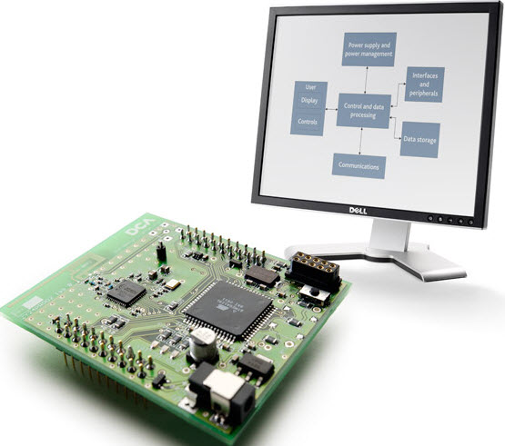
Embedded System Hardware:
An embedded system requires a hardware platform to interact with
various real-time inputs and outputs or variables. The hardware includes
controller like microcontroller or microprocessor, memory modules, I/O interfaces, display systems and communication modules, etc.
Embedded System Software:
This software allows programming in a desired fashion such that it
controls various operations. It is written in a high-level format,
compiled into code, and then dumped into hardware controllers.
Real-time embedded systems
are computer systems that perform the actions, such as monitoring,
responding and controlling external movement. The external environment
is connected to the computer system through sensors,
actuators and I/O interfaces. A real computer system embedded with a
computer system is known as real-time embedded system. A real-time
embedded system is used in different fields such as military, government
sectors and in medical.
Robotic Real Time Projects in Embedded Systems
Embedded systems can be used in many of the real-time applications such as automobiles, robotics, industries, etc. The following real-time projects are related to robotics technology.
1. Voice Controlled Robotic Vehicle with Long Distance Speech Recognition
The aim of this project is to control a robotic vehicle by voice commands for remote operation. An 8051 microcontroller
is used with a speech recognition module to perform the desired
operation. It uses an 8051 micro controller, a speech recognition
module, a push button, an RF module, an encoder, a decoder, a
motor-driver IC, DC motors, batteries and other miscellaneous
components.
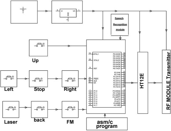
Vehicle movements like left, right, up
and down can be performed by using push buttons or voice commands by a
speech-recognition module which is interfaced with the microcontroller.
Here, an encoder is used to encode the commands given to the
microcontroller by using the RF transmitter to transmit the signals at the frequency of 433 MHz.
Therefore, when signals that emerge by
pressing buttons, or the voice command signals corresponding to the
movement are received by the micrcontroller, it sends control signals to
the reciever circuit through the transmitter module.
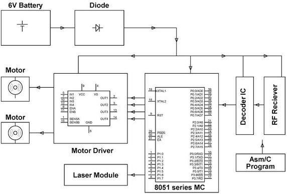
Upon receiving these signals, An RF
reciever transfers those signals to a decoder circuit wherein the binary
data is converted into a micrcontroller-level signal. Therefore, the
micrcontroller performs the desired movement from the transmitter
circuit. Laser module is interfaced with the microcontroller for detecting the operations performed by the robot even in dark places.
2. Touch screen-based Remote Controlled Robotic Vehicle for Store Management
This project involves controlling a robotic vehicle using a touch-screen display unit for remote operation. A touch-screen panel is placed at the transmitter end, and a pick-n-place robot
is placed at the receiver end to perform a task by responding to the
signals. The hardware components used in this project include an 8051
microcontroller, a touch-screen panel, antennas (transmitter- receiver
side), an encoder, a decoder, DC motors, a Robotic body, a battery, etc.

As discussed in the speech recognition
module of the above project, in this project also a touch screen module
sends the control signals corresponding to the vehicle movement to the
microcontroller. The controller subsequently sends those signals to the
encoder, and then to the transmitter that eventually transmits the
signals to the receiver circuit.
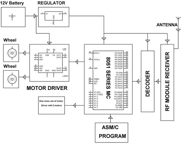
The antenna placed at the receiver end
receives the RF signals from the transmitting antenna, and decodes the
data, and then sends that data to the microcontroller. This set up has
four motors interfaced with the microcontroller: two motors for the
movement of the arm and gripper and the other two for the movement of
the body. All these motors are driven by a motor driver IC which
continuously receives the commands from the microcontroller.
__________________________________________________________________________________
The centre of telecommunications, electronics and robotics to be concern on R&D for :
- Laboratory of industrial robots : The model of automated production line allows you to develop practical skills in the organization of robotic cells and robotic levels of automated control systems.
- Laboratory of mobile robots : Laboratory robots and software allow to learn the principles of creating mobile robots, to understand the features of the use of mobile robot information devices and to develop practical skills in the implementation of mobile robot control algorithms.
- Laboratory of Physics and Electrical Machines : to explore the effect of the fundamental laws of physics. At the same time, the electrical machine equipment
- Laboratory of Modelling of Electronic Systems : modern software, which allows to execute the simulation of the work
of electric circuits and the designing of printed circuit boards. The
list of software includes:
- Electronic Design Automation package OrCAD;
- Functional Modelling (Simulation) System Proteus VSM;
- Modelling (Simulation) System of Industrial Standard NI Multisim;
- Graphical Programming System NI LabVIEW;
- Designing System for Microcontrollers AVR Studio;
- Designing System for PLIC (programmable logic integrated circuits) Xilinx ISE WebPACK and others.
- Laboratory of Embedded Systems and Digital Signal Processing : The laboratory is equipped with special debug kits with modern microcontrollers AVR, Freescale, STMicroelectronics, as well as programmable logic circuits XILINX. The equipment of laboratory allows designing and exploring of digital signal processing systems and intelligent control systems.
- Laboratory of Industrial Automation : control software systems and models of the production lines. The laboratory is designed for the research of the principles of industrial networks and engineering of the systems of automation based on industrial logic controllers.
- Laboratory of Subsurface Radiolocation : The laboratory is equipped with the ground penetrating radar
- Laboratory of Robotics and Students’ Research Work : The laboratory is equipped with software and hardware of production the prototypes of the electronic devices, including CNC machine tool LPKF Protomat S63, for the production of double-sided printed circuit boards. Soldering Equipment of the laboratory allows to carry out montage using PTH (Pin Through Hole) and SMT (Surface Mount Technology) technologies.
- Laboratory of Designing And Prototyping
- Laboratory of Telecommunications and Electro-Optical Systems: to explore the principles of the construction of telecommunications equipment.
- Global System for Mobile communications (GSM)
- Global Positioning System (GPS)
- Radio-Frequency Identification System (RFID);
- Optoelectronic Systems
- Digital Telephone Networks
- Radio Transmitting and Receiving Devices
- Antenna-Feeder Devices
- Laboratory of Electronics : This laboratory is equipped with typesetting fields for creating electrical circuits. All the research work is with the use of specialized laboratory measuring equipment.
________________________________________________________________________________
Control, Robotics, and Mechatronics
Control, robotics, and mechatronics are interdisciplinary areas
that have their own identity, and they also often form cohesive
interdisciplinary collaborations. Control engineering is the engineering
discipline that focuses on mathematical modeling of systems of a
diverse nature, analyzing their dynamic behavior, and using control
theory to create a controller that will cause the systems to behave in a
desired manner. Robotics is the science and technology of robots, and
their design, manufacture, and application.
Computational Intelligence
Computational intelligence (CI) focuses on the theory, design,
application, and development of biologically and linguistically
motivated computational paradigms combining elements of learning,
adaptation, evolution and fuzzy logic.
Computational intelligence originally developed as a branch of artificial intelligence but now it has a large enough extent to be recognized as a separate domain of research. In general, typical artificial intelligence techniques are top-to-bottom where, i.e., the structure of models, solutions, etc. is imposed from above. Computational intelligence techniques are generally bottom-up, where order and structure emerges from an unstructured beginning.
The areas covered by the term computational intelligence include: neural networks, connectionist systems, genetic algorithms, evolutionary programming, fuzzy systems, swarm intelligence, artificial immune systems and hybrid intelligent systems in which these paradigms are contained.
Computational intelligence is also closely related to soft computing, which indicates the difference from operations research, also known as hard computing. With similar problem domains, soft computing puts no conditions on the problem but also provides no guarantees for success, a deficiency which is compensated by the robustness of the methods.
Control
Control is an interdisciplinary branch of engineering and
mathematics dealing with the design, identification and analysis to
provide specific tasks system desired performance. In the earlier time,
system control mainly focused on automatic regulation used in industrial
control based on the concept of feedback. Based on transfer function,
classical control theory has been later been developed for
single-input-single-output and linear time-invariant systems. With the
rapid advancements in applied mathematics and computer science, control
theory entered the modern control era in 1970’s to handle
multi-input-multi-output and time-varying systems with high performance
and precision. In the last decade, control continues to advance rapidly
to intelligent control, distributed control, etc. when new
understandings and new technologies emerge.
Nowadays, control engineering is using control theories and advanced technologies to develop more sophisticated and reliable controllers with a wide range of applications from the flight and propulsion systems of commercial airliners, to the cruise control present in many modern automobiles, to tele-operations, and to real-time internet-based distributed control. It has permeated into every single part of our lives and will continues to play an important role in our societies.
Nowadays, control engineering is using control theories and advanced technologies to develop more sophisticated and reliable controllers with a wide range of applications from the flight and propulsion systems of commercial airliners, to the cruise control present in many modern automobiles, to tele-operations, and to real-time internet-based distributed control. It has permeated into every single part of our lives and will continues to play an important role in our societies.
Mechatronics
Mechatronics is a multi-disciplinary area incorporating
mechanical systems, electronics, and control theory for the design of
products and control processes. It relates to the design of systems,
devices and products aimed at achieving an optimal balance between basic
mechanical structure and its overall control. A few examples of
mechatronics systems are cruise control in a car, autofocus in camera,
robot controllers, manufacturing plants automation, car assembly,
autopilot system etc.
The latest research trend in Mechatronics focuses on efficient, fast, multi-component (sensors and actuators) modular/scalable system design. Real-time large-scale mechatronics systems coordinated over networks is another thrust. The challenge is integrating enough intelligence in a real-world system; where size and cost are the primary constraints.
Mechatronics will fuel technologies advancements such as intelligent space, robotic rooms, remote surgeries, autonomous vehicles, physical-cyber space integration transportation systems, distributed generation systems.
Robotics
“A robot is a machine that gathers information about its
environment and uses that information to follow instructions to do some
sort of work.” (The Tech Museum of Innovation, 2000) The robot sensory
system gathers specific information needed by the control system. The
robot control system directs the motion and sensory processing of a
robot. The robots mechanical system then produces motion that results in
manipulation or locomotion.
Robotics is the science and engineering concerned with the design, manufacture and application of robots, and computer systems for their control, sensory feedback, and information processing. The many types of robotic systems include robotic manipulators, robotic hands, mobile robots, walking robots, aids for disabled persons, tele-robots, and microelectro-mechanical systems. Robotics Engineers study electronics, computer science, artificial intelligence, mechatronics, nanotechnology, and bioengineering.


Robotics is the science and engineering concerned with the design, manufacture and application of robots, and computer systems for their control, sensory feedback, and information processing. The many types of robotic systems include robotic manipulators, robotic hands, mobile robots, walking robots, aids for disabled persons, tele-robots, and microelectro-mechanical systems. Robotics Engineers study electronics, computer science, artificial intelligence, mechatronics, nanotechnology, and bioengineering.
____________________________________________________________________
- GEN . MAC TECH Zone MARIA PREFER in electronic communication techniques
- ____________________________________________________________________