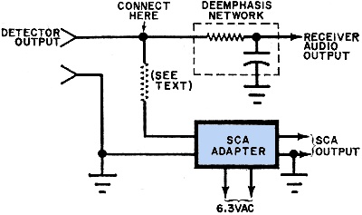
SCA adapter must be connected between detector and de-emphasis net
Simple Subsidiary Communications Authorization (SCA) Adapter
System (RBDS) which is responsible for your FM radio being able to display song title and station identification via a digital subchannel .
Subsidiary Communications Authorization (SCA) has been around as an analog subchannel for more than half a century. SCA (was) used for tasks such as book reading for the blind, telemetry, paging services, and most familiarly
a simple circuit for stripping the subcarrier off of the FM broadcast signal to permit a listener to avoid commercials,PSAs, weather reports, and other items that are played between songs.
Note the 6.3 VAC supply requirement, which is obviously a remnant from the readily available vacuum tube heater voltage transformers that were on their way out of common use.
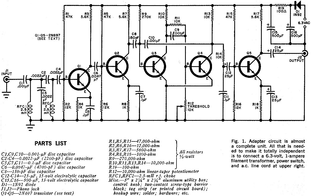
Subsidiary Communications Authorization (SCA) Adapter Schematic

These typical power supply designs contain a large mains transformer (which also provides isolation between the input and output) and a dissipative series regulator circuit. The regulator circuit could consist of a single zener diode or a three-terminal linear series regulator to produce the required output voltage. The advantage of a linear regulator is that the power supply circuit only needs an input capacitor, output capacitor and some feedback resistors to set the output voltage.
Linear voltage regulators produce a regulated DC output by placing a continuously conducting transistor in series between the input and the output operating it in its linear region (hence the name) of its current-voltage (i-v) characteristics. Thus the transistor acts more like a variable resistance which continually adjusts itself to whatever value is needed to maintain the correct output voltage.
Switch Mode Power Supplies, or SMPS, are becoming common place and have replaced in most cases the traditional linear ac-to-dc power supplies as a way to cut power consumption, reduce heat dissipation, as well as size and weight. Switch-mode power supplies can now be found in most PC’s, power amplifiers, TV’s, dc motor drives, etc., and just about anything that requires a highly efficient supply as switch-mode power supplies are increasingly becoming a much more mature technology.
By definition, a switch mode power supply (SMPS) is a type of power supply that uses semiconductor switching techniques, rather than standard linear methods to provide the required output voltage. The basic switching converter consists of a power switching stage and a control circuit. The power switching stage performs the power conversion from the circuits input voltage, VIN to its output voltage, VOUT which includes output filtering.
The major advantage of the switch mode power supply is its higher efficiency, compared to standard linear regulators, and this is achieved by internally switching a transistor (or power MOSFET) between its “ON” state (saturated) and its “OFF” state (cut-off), both of which produces lower power dissipation. This means that when the switching transistor is fully “ON” and conducting current, the voltage drop across it is at its minimal value, and when the transistor is fully “OFF” there is no current flow through it. So the transistor is acting like an ideal switch.
As a result, unlike linear regulators which only offer step-down voltage regulation, a switch mode power supply, can offer step-down, step-up and negation of the input voltage using one or more of the three basic switch mode circuit topologies: Buck, Boost and Buck-Boost. This refers to how the transistor switch, inductor, and smoothing capacitor are connected within the basic circuit.

The Buck Switching Regulator
We can see that the basic circuit configuration for a buck converter is a series transistor switch, TR1 with an associated drive circuit that keeps the output voltage as close to the desired level as possible, a diode, D1, an inductor, L1 and a smoothing capacitor, C1. The buck converter has two operating modes, depending on if the switching transistor TR1 is turned “ON” or “OFF”.
When the transistor is biased “ON” (switch closed), diode D1 becomes reverse biased and the input voltage, VIN causes a current to flow through the inductor to the connected load at the output, charging up the capacitor, C1. As a changing current flows through the inductor coil, it produces a back-emf which opposes the flow of current, according to Faraday’s law, until it reaches a steady state creating a magnetic field around the inductor, L1. This situation continues indefinitely as long as TR1 is closed.
When transistor TR1 is turned “OFF” (switch open) by the controlling circuitry, the input voltage is instantly disconnected from the emitter circuit causing the magnetic field around the inductor to collapse inducing a reverse voltage across the inductor. This reverse voltage causes the diode to become forward biased, so the stored energy in the inductors magnetic field forces current to continue to flow through the load in the same direction, and return back through diode.
Then the inductor, L1 returns its stored energy back to the load acting like a source and supplying current until all the inductor’s energy is returned to the circuit or until the transistor switch closes again, whichever comes first. At the same time the capacitor also discharges supplying current to the load. The combination of the inductor and capacitor forms an LC filter smoothing out any ripple created by the switching action of the transistor.
Therefore, when the transistor solid state switch is closed, current is supplied from the supply, and when the transistor switch is open, current is supplied by the inductor. Note that the current flowing through the inductor is always in the same direction, either directly from the supply or via the diode but obviously at different times within the switching cycle.
As the transistor switch is being continuously closed and opened, the average output voltage value will therefore be related to the duty cycle, D which is defined as the conduction time of the transistor switch during one full switching cycle. If VIN is the supply voltage, and the “ON” and “OFF” times for the transistor switch are defined as: tON and tOFF, then the output voltage VOUT is given as:
Buck Converter Duty Cycle

The buck converters duty cycle can also be defined as:

So the larger the duty cycle, the higher the average DC output voltage from the switch mode power supply. From this we can also see that the output voltage will always be lower than the input voltage since the duty cycle, D can never reach one (unity) resulting in a step-down voltage regulator. Voltage regulation is obtained by varying the duty cycle and with high switching speeds, up to 200kHz, smaller components can be used thereby greatly reducing a switch mode power supply’s size and weight.
Another advantage of the buck converter is that the inductor-capacitor (LC) arrangement provides very good filtering of the inductor current. Ideally the buck converter should be operated in a continuous switching mode so that the inductor current never falls to zero. With ideal components, that is zero voltage drop and switching losses in the “ON” state, the ideal buck converter could have efficiencies as high as 100%.
As well as the step-down buck switching regulator for the basic design of a switch mode power supply, there is another operation of the fundamental switching regulator that acts as a step-up voltage regulator called the Boost Converter.
Boost Switch Mode Power Supply
The Boost switching regulator is another type of switch mode power supply circuit. It has the same types of components as the previous buck converter, but this time in different positions. The boost converter is designed to increase a DC voltage from a lower voltage to a higher one, that is it adds too or “Boosts” the supply voltage, thereby increasing the available voltage at the output terminals without changing the polarity. In other words, the boost switching regulator is a step-up regulator circuit, so for example a boost converter can convert say, +5 volts to +12 volts.
We saw previously that the buck switching regulator uses a series switching transistor within its basic design. The difference with the design of the boost switching regulator is that it uses a parallel connected switching transistor to control the output voltage from the switch mode power supply. As the transistor switch is effectively connected in parallel with the output, electrical energy only passes through the inductor to the load when the transistor is biased “OFF” (switch open) as shown.
The Boost Switching Regulator

In the Boost Converter circuit, when the transistor switch is fully-on, electrical energy from the supply, VIN passes through the inductor and transistor switch and back to the supply. As a result, none of it passes to the output as the saturated transistor switch effectively creates a short-circuit to the output. This increases the current flowing through the inductor as it has a shorter inner path to travel back to the supply. Meanwhile, diode D1becomes reverse biased as its anode is connected to ground via the transistor switch with the voltage level on the output remaining fairly constant as the capacitor starts to discharge through the load.
When the transistor is switched fully-off, the input supply is now connected to the output via the series connected inductor and diode. As the inductor field decreases the induced energy stored in the inductor is pushed to the output by VIN, through the now forward biased diode. The result of all this is that the induced voltage across the inductor L1reverses and adds to the voltage of the input supply increasing the total output voltage as it now becomes, VIN + VL.
Current from the smoothing capacitor, C1 which was used to supply the load when the transistor switch was closed, is now returned to the capacitor by the input supply via the diode. Then the current supplied to the capacitor is the diode current, which will always be ON or OFF as the diode is continually switched between forward and reverse status by the switching actions of transistor. Then the smoothing capacitor must be sufficiently large enough to produce a smooth steady output.
As the induced voltage across the inductor L1 is negative, it adds to the source voltage, VINforcing the inductor current into the load. The boost converters steady state output voltage is given by:

As with the previous buck converter, the output voltage from the boost converter depends upon the input voltage and duty cycle. Therefore, by controlling the duty cycle, output regulation is achieved. Not also that this equation is independent of the value of the inductor, the load current, and the output capacitor.
We have seen above that the basic operation of a non-isolated switch mode power supply circuit can use either a buck converter or boost converter configuration depending upon whether we require a step-down (buck) or step-up (boost) output voltage. While buck converters may be the more common SMPS switching configuration, boost converters are commonly used in capacitive circuit applications such as battery chargers, photo-flashes, strobe flashes, etc, because the capacitor supplies all of the load current while the switch is closed.
But we can also combine these two basic switching topologies into a single non-isolating switching regulator circuit called unsurprisingly, a Buck-Boost Converter.
Buck-Boost Switching Regulator
The Buck-Boost switching regulator is a combination of the buck converter and the boost converter that produces an inverted (negative) output voltage which can be greater or less than the input voltage based on the duty cycle. The buck-boost converter is a variation of the boost converter circuit in which the inverting converter only delivers the energy stored by the inductor, L1, into the load. The basic buck-boost switch mode power supply circuit is given below.
The Buck-Boost Switching Regulator

When the transistor switch, TR1, is switched fully-on (closed), the voltage across the inductor is equal to the supply voltage so the inductor stores energy from the input supply. No current is delivered to the connected load at the output because diode, D1, is reverse biased. When the transistor switch is fully-off (open), the diode becomes forward biased and the energy previously stored in the inductor is transferred to the load.
In other words, when the switch is “ON”, energy is delivered into the inductor by the DC supply (via the switch), and none to the output, and when the switch is “OFF”, the voltage across the inductor reverses as the inductor now becomes a source of energy so the energy stored previously in the inductor is switched to the output (through the diode), and none comes directly from the input DC source. So the voltage dropped across the load when the switching transistor is “OFF” is equal to the inductor voltage.
The result is that the magnitude of the inverted output voltage can be greater or smaller (or equal to) the magnitude of the input voltage based on the duty cycle. For example, a positive-to-negative buck-boost converter can convert 5 volts to 12 volts (step-up) or 12 volts to 5 volts (step-down).
The buck-boost switching regulators steady state output voltage, VOUT is given as:

Then the buck-boost regulator gets its name from producing an output voltage that can be higher (like a boost power stage) or lower (like a buck power stage) in magnitude than the input voltage. However, the output voltage is opposite in polarity from the input voltage.
Switch Mode Power Supply Summary
The modern switch mode power supply, or SMPS, uses solid-state switches to convert an unregulated DC input voltage to a regulated and smooth DC output voltage at different voltage levels. The input supply can be a true DC voltage from a battery or solar panel, or a rectified DC voltage from an AC supply using a diode bridge along with some additional capacitive filtering.
In many power control applications, the power transistor, MOSFET or IGFET, is operated in its switching mode were it is repeatedly turned “ON” and “OFF” at high speed. The main advantage of this is that the power efficiency of the regulator can be quite high because the transistor is either fully-on and conducting (saturated) or full-off (cut-off).
There are several types of DC-to-DC converter (as opposed to a DC-to-AC converter which is an inverter) configurations available, with the three basic switching power supply topologies looked at here being the Buck, Boost, and the Buck-Boost switching regulators. All three of these topologies are non-isolated, that is their input and output voltages share a common ground line.
Each switching regulator design has its own unique properties with regards to the steady-state duty cycles, relationship between the input and output current, and the output voltage ripple produced by the solid-state switch action. Another important property of these switch mode power supply topologies is the frequency response of the switching action to the output voltage.
Regulation of the output voltage is achieved by the percentage control of the time that the switching transistor is in the “ON” state compared to the total ON/OFF time. This ratio is called the duty cycle and by varying the duty cycle, (D the magnitude of the output voltage, VOUT can be controlled.
The use of a single inductor and diode as well as fast switching solid-state switches capable of operating at switching frequencies in the kilohertz range, within the switch mode power supply design, allows for the size and weight of the power supply to be greatly reduced. This is because there would be no large and heavy step-down (or step-up) voltage mains transformers within their design. However, if isolation is required between the input and output terminals, a transformer must be included before the converter.
The two most popular non-isolated switching configurations are the buck (subtractive) and the boost (additive) converters.
The buck converter is a type of switch-mode power supply that is designed to convert electrical energy from one voltage to a lower one. The buck converter operates with a series connected switching transistor. As the duty cycle, D < 1, the output voltage of the buck is always smaller than the input voltage, VIN.
The boost converter is a type of switch-mode power supply that is designed to convert electrical energy from one voltage to a higher one. The boost converter operates with a parallel connected switching transistor which results in a direct current path between VINand VOUT via the inductor, L1 and diode, D1. This means there is no protection against short-circuits on the output.
By varying the duty cycle, (D) of a boost converter, the output voltage can be controlled and with D < 1, the DC output from the boost converter is greater than input voltage VINas a consequence of the inductors self-induced voltage.
Also, the output smoothing capacitors in Switch-mode Power Supplies is assumed to be very large, which results in a constant output voltage from the switch mode supply during the transistors switching action.
Simple SCA Adapter
FM Music Sans Commercials

Many FM broadcast stations transmit a secondary frequency-modulated subcarrier that is offset from the regular carrier frequency by 67.5 kHz. This sub-carrier channel (called SCA for Subsidiary Communications Authorization) provides the listener with continuous music programming that is uninterrupted by commercials, news, weather, or other reports. The SCA should not be confused with the 38-kHz subcarrier normally used to carry the complementary channel in normal stereo FM broadcasts; it is a separate system which no home entertainment receiver is designed to receive.
all you need is a simple multiplex adapter that can extract the program material without interference from the "normal" program channel transmissions from the FM station.
Adding the SCA Adapter (described in this article) to your FM receiver will in no way interfere with the receiver's normal operation. If anything, it will add to the receiver's versatility by providing an extra source of entertaining music.
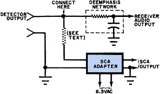
For proper operation, SCA adapter must be connected between detector and
de emphasis - Net
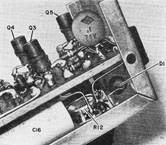
How It Works. Referring to Fig. 1, the frequency-modulated SCA subcarrier is introduced into the adapter through input jack J1 where it encounters a 67.5-kHz parallel-tuned circuit consisting of radio frequency choke RFC1 and capacitor C3. Then it is passed through a high-pass filter made up of C2, C4, and RFC2. From here, the frequency-modulated sub-carrier is amplified and limited by Q1 and Q2, respectively. At this point, the frequency modulation will have been converted to a series of pulses whose frequency is the same as that of the original frequency modulation.
Once amplified and limited, the signal is coupled to monostable multi vibrator stage Q3-Q4. Here, Q3 is normally conducting, while Q4 is held in cutoff. Potentiometer R12 acts as a "threshold" control, allowing only the higher amplitude 67.5-kHz subcarrier signals to trigger the multivibrator. Each time the multivibrator fires, a negative pulse is generated at the collector of Q4.
Since the width of the generated pulse is essentially independent of the triggering rate, the average voltage level appearing at the collector of Q4 will be directly proportional to the triggering frequency (the 67.5-kHz modulation up to the point where Q4 is cut off completely all the time. This point is slightly above the audio spectrum; therefore, the multivibrator will deliver an output for the full subcarrier modulation range.
Power for the SCA adapter is derived from any 6.3-volt, 60-Hz, source. A built-in half-wave rectifier/filtering circuit, consisting of D1 and C15, C16 and R19, provide the d.c. voltage required for proper operation of the adapter.
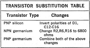
Although the SCA Adapter so far described makes use of five commonly available npn silicon transistors, germanium or pnp transistors can be substituted. Merely change the polarities or values of a few components.
Construction. The circuit of the SCA Adapter is really very simple, lending itself to just about any type of chassis construction you prefer. While the photos show the original prototype assembled on a double-row solder-terminal tag strip, which is essentially point-to-point wiring, a printed circuit board layout would have been just as appropriate for assembly.
The circuit can be assembled in any enclosure you choose. A 5" X 2 1/4" X 2 1/4" aluminum utility box was used for the prototype, with J1 and J2 mounted at opposite ends of the top surface. Threshold control R12 was also mounted to the top, while to one side is located a screw-type barrier block for bringing in the 6.3 volts a.c. for the power supply circuit.
Installation and Use. To operate properly, the SCA adapter must be electrically connected to your receiver. This is a simple process that can be performed in a couple of minutes.
Before digging into your receiver (or tuner), carefully study its schematic diagram to locate the detector stage and resistor/capacitor de-emphasis network.

Although a printed circuit board or multi-lug terminal strips could be used, wiring is just as simple with a parallel-row terminal board having 13 solder lugs per row
Adapter's input must be connected to a point between the detector output and the de-emphasis network. If the connection is made after the de-emphasis network, no SCA signal will pass through!
The filter (SCA Adapter) was designed to operate most efficiently with a 3000-ohm load. So, it may be necessary to couple the adapter to the receiver circuit via an isolation resistor with a value of a few thousand ohms, depending on your particular receiver.
Now, connect a twisted-pair cable between the 6.3-volt a.c. winding on your receiver's power transformer and the screw-type barrier block on the adapter. If 6.3 volts a.c. is not available from your receiver, use a separate 6.3-volt filament transformer. Then connect a shielded audio cable from the adapter's output jack to the auxiliary (AUX) input jack on the rear apron of your receiver.
Turn on and tune the receiver to a local FM station known to be broadcasting SCA program material. Set the receiver's source switch to AUX and function switch to MONO, and adjust threshold for the clearest audio. (Note: in some receivers, when the source switch is moved out of the TUNER or FM position, the power is disconnected from the tuner. In this case, connecting the output of the adapter to the receiver's AUX input will not work - a separate amplifier will be required unless you can figure a way of restoring power to the tuner when the source switch is in the AUX position.
Tuning across the dial, you may find that several SCA programs are available. This is true especially in the large cities where different types of background music are required by the subscribers. So much the better for your choice of programs.
220V Automatic Light Switch Circuit

This light sensitive automatic light switch circuit is intended to be connected at the main 220V supply. The circuit will connect a 220V lamp at the nightfall and disconnects it in the morning light. The switching is made without a relay in order to avoid problems with the electric arc and noise caused by inductance coil and contacts.
The automatic light switch is powered from the 220V mains through R10, C4, D3, D2 and C3. A reference voltage source, D1, feeds with 8.2 V the circuit for measuring light, R2-P1. At lower light intensity, LDR’s resistance, R2, increases and therefore the P1 voltage falls, so will fall the gate-source voltage of FET’s T1.
When the switch S1 is closed, R3-C2 time constant makes that the gate voltage of T1 to vary slower then R2 resistance. This is necessary to prevent the circuit reaction at rapid changes of ambient light intensity.
T1, T2, R4, R5, R6 and R8 forms a trigger Schmitt. Normally, T1 is open and T2 is blocked. When the gate voltage of the FET goes below a certain level, T2 starts to conduct and so does T2 which will provides the necessary gate current to boost the triac Tri1 in order to connect the load (220V lamp).
Caution! Because there are many points that are connected at 220V it is essential to apply a good insolation. Do not work on the circuit when is connected to the mains.
Components list
R1 = 2.2K
R2 = LDR
R3 = 150K
R4 = 15k
R5 = 10k
R6 = 27k
R7 = 560Ω
R8 = 1.2k
R9 = 1.2M
R10 = 470Ω
R11 = 100Ω
C1 = 4.7µF/16V tantalum
C2 = 47µF/16V
C3 = 1000µF/16V
C4 = 470nF/250V~(630V)
C5 = 100nF/630V
D1 = 8.2V zener
D2 = 1N4001
D3 = 15V/1W zener
D4 = LED
T1 = BS250
T2 = BC557B
T3 = BC547B
Tri1 = TIC226M
F1 = 5A
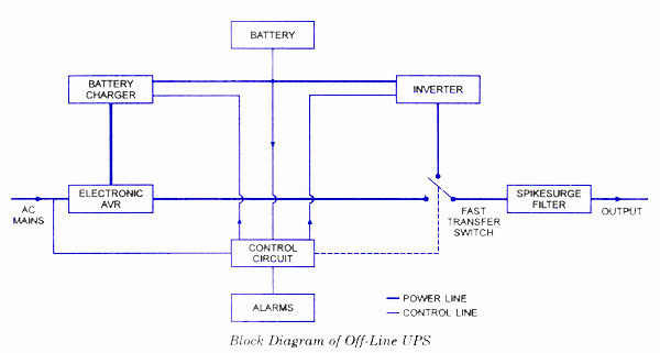
CIRCUIT DIAGRAM OF UPS SYSTEM

a 12 volt lead acid automatic battery charger that shut off the charging process once the battery attains full charge. This prevents overcharging of the battery so that, the charger can be left unattended.
If the terminal voltage of the battery reduces below the set level, say 13.5 volts, the circuit automatically turns on to the charge mode.
Charging current as well as the power to the circuit is obtained from a 0-18 volt 2 Ampere step-down transformer. The low voltage AC is rectified by the bridge rectifier comprising D1 through D4 and made ripple free by the smoothing capacitor C1. For charging purpose, 18 volt DC is used while to power the circuit, 9 volt regulated DC from IC1 is used.
IC2 (CA3140) is used as a simple voltage comparator to drive the relay. Its inverting input gets 4.7 volt reference voltage from the Zener ZD, while the non inverting input gets an adjustable voltage through the POT VR1.So normally, the inverting input pin 2 gets higher voltage from the Zener (as adjusted by VR1) and output of IC2 remains low. T1 then remains off keeping the relay off. The charging current passes to the battery through the NC (Normally Connected) contacts of the relay.
When the terminal voltage of the battery increases to 13.5 volts, pin 3 of IC2 gets higher voltage than pin2 and the output of IC2 becomes high. This activates the relay and the contacts break. Charging current to the battery cut off and the relay remains as such since the battery voltage(13.5V or more) keeps the voltage at pin3 of IC2 is higher than that of pin 2.
Charger Settings
Before connecting the battery, set the input voltage to IC2 using a fully charged battery or variable power supply. Turn the switch S1 to the off position and switch on the power. Then connect a fully charged battery/ variable power supply to test points TP observing polarity. Measure the input voltage to pin 3 of IC2.
Slowly adjust VR1 till the input voltage to pin 3 of IC2 raises to 5 volts. At this point, relay should energize and Red LED turns on. Then connect the battery for charging and switch on S1. If the battery takes charge, current to pin 3 of IC2 will be low since most of the current drain occurs into the battery. This keeps the relay off. When the battery voltage increases above 13.5 volts, no more current passes into the battery, so that the voltage at pin3 of IC2 rises and relay turns on.
Solar Tracker System
The solar panels are operating at optimal parameters when they are at the perfect right angle to the sun. Unfortunately this is accomplished only if solar panels are rotated by the sun. This is the purpose of this diy solar tracker system or if you have an Arduino board then you can build that uses a servo.
The solar tracker circuit uses a window comparator to maintain the motor in a idle state as long as the two LDRs are under the same illumination level. In this case, half the voltage is applied to the noninverting input of A1 and to the inverting input of A1.
solar tracking components
- T1, T3 = BD239, BD139
- T2, T4 = BD240, BD140
- A1, A2 = 1/2 of LM324
- Diodes = 1N4001
When the sun position is changing so does the illumination level on the LDRs and the input voltage for the window comparator is no longer half of the supply voltage thereby the output of the comparator generates informations for the motor that rotates the panels for tracking the sun.
diy sun tracking sensor
diy sun tracking sensor
P1 and P2 are adjusted in such way that the motor stands still when the LDRs get the same amount of solar light. If less light reaches LDR2 than LDR1, the voltage in point A increases to more than half of the power supply voltage. As a result the output of A1 is HIGH and T1 and T4 transistors conduct. In this situation the motor is starting.
If the angle of the solar light is changing again and the voltage in point A decreases at less than power supply voltage, the output of A2 goes HIGH and T3 and T2 transistors conduct. As a result the motor is rotating in opposite direction.
For solar panels control is best to use small motors with a suitable voltage and a maximum working current of 300 mA. This solar tracker system is used for tracking the sun only in one plane, the horizontal one. If you want to track the solar light in the vertical plane you need to build a separate sun tracker circuit.
This is a simple and practical analog solar panel tracker circuit. Using four LDR (light dependent resistor) as a sensor in detecting the light source arranged as illustrated. When the light hit the LDR in a certain position, it will activate the circuit and trigger the relay to turn the slewing motor in the right direction until the sensor is fully shaded under its cover stopping the motor to its rest condition.
AB. WXO MASTER AND SLAVE LOAD
This circuit will automatically switch on several mains-powered "slave" loads when a "master" load is turned on
for example , it will switch on the amplifier and the CD player in a stereo system when the receiver turned on . it works by the sensing current draw of " the Master " device through a low value high wattage resistor using a comparator .
the output of that comparator then the Switches on the " slave relay " . the circuit can be built into a power bar . extension cord or power center to provide a convenient set of " smart " outlets that switched on when the master appliance is powered ( turned on the computer monitor and the computer , printer and the other peripherals come on as well ) .
BC, WXO Circuit Diagram of Variable Voltage Power Supply From Fixed Voltage Regulator
We will show you how to design a Variable Voltage Power Supply from Fixed Voltage Regulator like 7805 IC.
78XX and 79XX are the two series of three pin voltage regulator available in the market. 78XX series of the voltage regulator is for the positive voltage supply i.e. if you need a +5V supply, then 7805 voltage regulator can be used. While 79XX series is for negative supply, i.e. if you need a -5V supply, then 7905 regulator is used.
Voltage regulators like 7805 are used to offer fixed voltage at the output terminal and does not depend on the variations at input voltage supplied (as long as it is greater than the required voltage).
What if you want a range of output voltage with the help of a single Linear Voltage Regulator IC? It is possible to implement this idea. I will now show you how to implement a Variable Voltage Power Supply from Fixed Voltage Regulator.
LM317 is a simple Variable Voltage Regulator IC that can be used to produce voltages in the range of 1.5V to 37V. But you can produce the same from a fixed voltage regulator like 7805 as well (although not the same range). This can be achieved by adding two resistors.
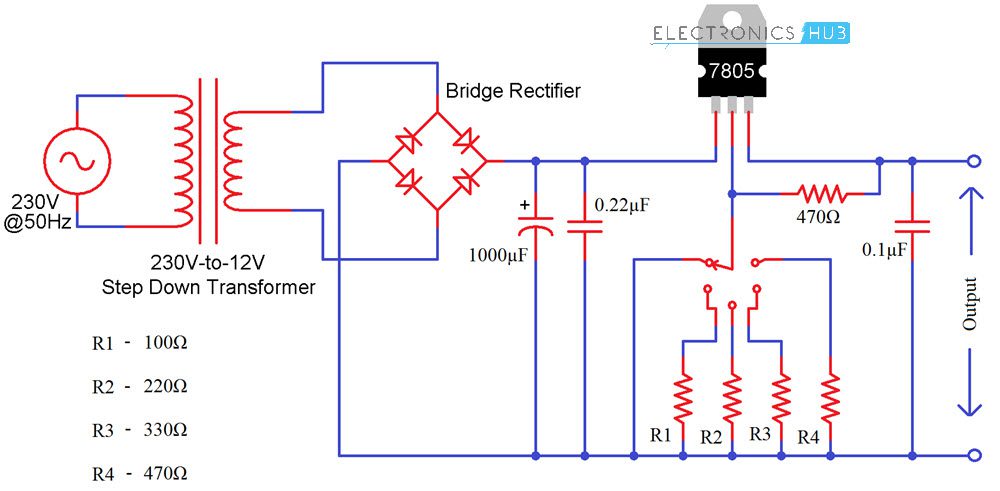
Components Required
- 230V to 12V Step Down Transformer
- Bridge Rectifier
- 7805 Regulator IC
- 1000μF Capacitor
- 0.22μF Capacitor
- 0.1μF Capacitor
- 470Ω Resistor x 2
- 100Ω Resistor
- 220Ω Resistor
- 330Ω Resistor
- Mini Breadboard
- Connecting Wires
Circuit Design
Initially, the primary of the 230V to 12V Step Down Transformer is connected to the AC Mains supply while the secondary is connected to a bridge rectifier. The output of the bridge rectifier is filtered out using a capacitor and is given to the 7805 Voltage Regulator IC.
A 0.22μF Capacitor is connected between INPUT and COMM (GND of 7805) while a 0.1μF Capacitor is connected between OUTPUT and COMM.
Now coming to the interesting part. A 470Ω Resistor is connected between the COM and OUT. A rotary switch is used to switch between output resistors and the following resistors are connected to the switch: 100Ω, 220Ω, 330Ω and 470Ω.
WARNING: If We are using AC Mains Supply as the source, be extremely careful when making the connections.
a Variable Voltage Power Supply from Fixed Voltage Regulator is implemented here. The main principle behind the working of this project is very simple.
Connect two resistors R1 and R2 as shown in the image below: one between the output and GND Pin and the other between GND Pin and GND of power supply.
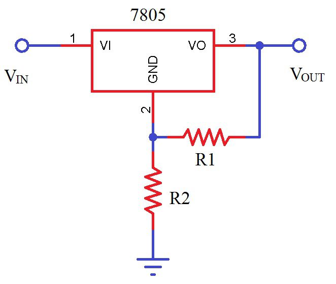
The amount of current flowing through R2 is a combination of current through R1 and the standby current of 7805. Depending on the output voltage requirement, we can calculate the value of this resistor and finally the output voltage can be calculated as follows.
VOUT = VREG + R2 * (VREG/R1 + IS)
where VREG = 5V (for 7805) and
IS = standby current of 7805 (≈2.5mA).
Based on the above calculations, you can get anywhere between 5V and 12V using a 7805 Regulator from a 12V Supply.
How to Calculate the Value of Resistance for the Different Voltages?
Imagine that the resistor which is attached between the com terminal and the output terminal of regulator has a value of 470Ω. This implies that the value of current is 10.6 mA (as V =5V furthermore V=IR).
Among the rotary switch and ground there is some amount of standby current of 2.5 mA approx. Hence about 13.1 mA of overall current is available.
Now assume that from the circuit we need 5V to 12V. With the regulator output we directly got 5V minimum. While if there is a need of 12V, then between com and output 5V is available and for the rest 7V we need to select the appropriate value of the resistor.
Here R =?
V = 7V
I =13.1mA
Therefore V =I*R
R = 543ohm
V = 7V
I =13.1mA
Therefore V =I*R
R = 543ohm
Hence, we have to attach resistor of 543 Ω with 470 Ω so to obtain the wanted output i.e. 12V. While it is difficult for us to get such a value of the resistor in the market so we can use the nearby value of the resistor i.e. 560 Ω.
Now if we wish to have some other voltage from 5V to 12V then we have to attach some other value of the resistor.
Suppose we need 6V, then
V =6V
I = 10.6mA
R = 6V/10.6mA
R = 566 Ω
I = 10.6mA
R = 6V/10.6mA
R = 566 Ω
But the resistor R1 is already on 470Ω which is already connected in the circuit, hence for 6V value of the resistor will be 100 Ω approximately (566-470=96).
In the same manner for different voltages different value of resistance will calculated. In spite of the different values of resistors available, a variable resistor can be used in the circuit to get different values of voltage.
Important Notes
- When switching from one resistor to other, the load will get 12V.
- So, before switching, make sure that the load is disconnected (or you can completely switch off the power supply, make a switch and then switch on the power supply).
Mains Operated LED Light Circuit Diagram
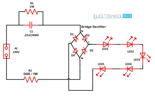
Components used in this Circuit
- Bridge rectifier – 1
- Resistor (R1) – 1MΩ
- Resistor (R2) – 560Ω / 1W
- Capacitor (C1) – 0.22uF / 400V)
- LEDs – 5
- Breadboard
- Connecting Wires
Mains Operated LED Circuit Explanation
This simple circuit is based on simple components: Bridge rectifier, resistors, LEDs and capacitor. All the components used in this circuit are easily available in market. So you can make this circuit and install in your homes and offices. Before understanding the working of circuit first have a look on the component description.
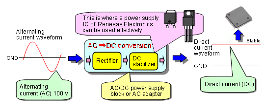
Rectifier
A rectifier is an electronic circuit used for converting alternating current (AC) to direct current(DC). And the process of converting alternating current to direct current by allowing one way electron flow is called as rectification. In full wave rectifier four diodes are connected in a circuit to form a bridge. In this approach, we are utilizing both positive and negative cycles of AC.
A bridge rectifier contains four diodes D1, D2, D3, D4 connected to form a bridge as shown in figure. Hence this arrangement is known as a bridge rectifier.
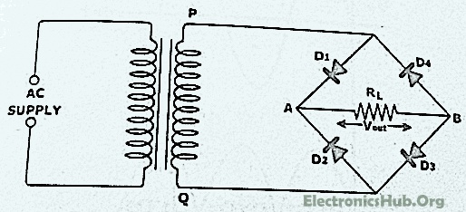
Bridge Connection of Diodes
Working of Bridge Rectifier
The AC signal to be rectified is applied to the diagonally opposite ends of the bridge through the transformer. Between another two ends of the bridge, The load resistance RL is connected.
During positive half cycle of secondary voltage, The end P become positive and end Q negative. Thus Diode D1 and D3 will become forward bias and start conducting , while diode D2, D4 are reversed bias.
Diode D1 and D3 are in series with the load resistance RL hence current flows through RL as shown in figure.
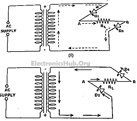
D1 and D3 Series Connection with Load Resistance RL
During negative half cycle of secondary voltage, the P end becomes negative and Q end become positive. Diode D2 and D4 are forward biased hence they start conducting . Whereas diode D1 and D3 are reversed biased.
Diode D2 and D4 are in series with the load resistor RL hence current flows through RL as shown in figure. It may be seen that again current flows from A to B through the load i.e. in the same direction as for the positive half cycle. Thus DC voltage is obtained across load RL . Output waveform of a bridge rectifier is shown in figure below. The advantage of Bridge rectifier is that its output is higher than of full wave and half wave rectifier.
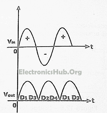
Output waveform of a bridge rectifier
LED
Light emitting diode are different from other diodes as they emit light and hence referred as light emitting diode. LED are available in RED, GREEN, BLUE color.
Resistor
All material have some type of opposition to the current flow. This opposition is called resistance. The resistance of a material is determine by the number of free electrons in the material. There are various type of resistor available such as carbon film, carbon composition, filament resistor and many more which can be used in an electronics or electrical circuit to determine the resistance.
Resistance of circuit depends upon p, L and A with the following equation.
R = p*(L/A)
Capacitor
The capacitor is a device that store electrical energy and capacitance is the amount of electrical energy stored at a given voltage drop by capacitor. A device specially designated to have a certain value of capacitance is called a capacitor. The capacitor has the ability to store electrons and release them at later stage. The capacitor is generally consist of two metal plate which are separated by a non conducting material called as dielectric.
Diode
Diode is an electronic device which allows current to flow only in one direction. Diodes are forward by joining N type and P type semiconductors. The N type semiconductor contains free electrons that move through the material. Similarly P type semiconductor contains holes. Electrons from the N type which are near the junction cross the junction and fill in the holes in P type material. Similarly holes near the junction of P type material, crosses the junction and occupy the place of electrons. A depletion layer is formed at the junction of the PN semiconductor.
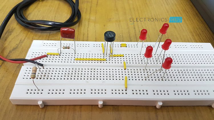
Mains Operated LED Light Circuit Working
Working of circuit is very simple. Assemble the circuit properly as shown in circuit diagram. Now apply AC mains. Resistor R2 is used as current limiting component and resistor R1 is used with capacitor C1 so that it will discharge the capacitor which prevents lethal shock.
Now this power supply is provided to the bridge rectifier circuit which will convert the AC to DC and also reduces the voltage with the help of current limiting components. Now this power supply is passed to LEDs and the LED connected at the output start glowing. You can use bridge rectifier available in market or you can make your own with the help of four diodes. Maximum you can use up to 20 LEDs.
Advantages of LED Bulbs
- LED bulbs have 10 times longer life in comparison to fluorescent and incandescent lights.
- LED bulbs does not contain filament so there is less chances of damage.
- Common incandescent bulb become hot and generate lot of heat in the room while LED bulb prevents the heat build up and helps in reducing the air conditioning cost in room.
- Power consumption of LED lamp is approx. 2-17 watt 1/3 in comparison to fluorescent lamp. So if you LED bulb you can save much on your electricity bill.
- As power consumption of LED lamp is very less, use in solar panels is increasing.
- Many people are using inverters in their home and now they are using LED lights with inverters because this will also increase the time period for which inverters can support LED light.
- Initial cost of LED bulb is more in comparison to fluorescent bulb with they have long life and they can be easily move from one place to another without breakage and save electricity also. Therefore LED bulb is more efficient than fluorescent bulb.
- LED bulbs are not sensitive to temperature or humidity.
- LED bulb does not contain mercury also hence do not provide harm to environment also.
- LED lights will turn on instantly.
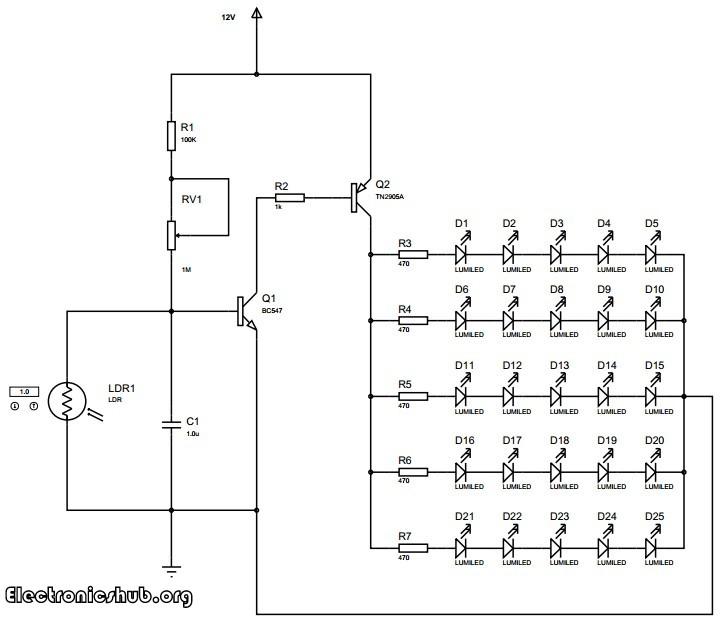
Auto Night Lamp Using High Power LED
Auto Night Lamp Using High Power LEDs is a circuit which turns ON the LED lights interfaced to it at night time and it turns OFF the lights automatically when it is day. Usage of LEDs is growing day by day due to the advantages they provide compared to the conventional filament bulbs or fluorescent lamps. They provide good quality of white light with a better intensity compared to others. They also consume less power compared to their alternatives.
This circuit explain the light intensity control of night lamp using high power LEDS.The element which is used for sensing light in the circuit is the light dependent resistor. The resistance of the light dependent resistor depends on the light incident on it. If the intensity of light incident on it is more, then the resistance of the circuit decreases. If the intensity of light incident on it decreases, then the resistance of the device increases. We are making use of this property of the light dependent resistor to detect the light and thereby operate the LEDs. We are arranging twenty five light emitting diodes in an array such that five LEDs are in series and five such series LEDs are arranged in parallel.
Circuit Diagram of Auto Intensity Control of LED Lights
Working
The transistors are used in saturation mode. They are used as electronic switches in this mode. The transistor BC547 is a general purpose NPN transistor which is used to further switch the LEDs. This is a power transistor with a heat sink. The heat sink helps the transistor to dissipate the generated heat into air so that the transistor can handle higher power loads than it can do without the heat sink.
The entire circuit along with the LEDs is powered by a 12V DC power supply. A battery based DC power supply is usually preferred. However, you can use a ac rectified and regulated power supply.
The LEDs used in the circuit are high powered white LEDs. The intensity of light produced by these LEDs equals an ordinary fluorescent bulb. The lighting produced is sufficient for reading or to do any other daily activity. The circuit can be assembled on a printed circuit board with all the components neatly arranged and the LEDs placed in order. Try to place the LEDs maintaining a distance of about 1 cm between the LEDs so that the the lighting will be well distributed in your room.
Intelligent Unambiguous Night Lamp Switcher
While making a night lamp switcher, there are many aspects which needs to be taken into consideration without which there is a possibility of destroying the home appliances and lights. In this circuit, strict measures are taken to ensure that the lights to be operated are not damaged because of switching. In general, if we make a simple automatic night lamp switcher, it may turn ON the lights when it is dark. But here comes a problem. When the level of darkness is approaching, the circuit may get successive signals of dark and light with little time intervals. This may cause the circuit to repeatedly turn ON and OFF the lights at a high frequency which can possibly damage our lights within a few minutes or hours. This happens every time at evening as well as in the morning when the light intensity crosses a value for which our circuit is sensitive and toggles the switch.
In this circuit, it is not only a simple automatic light switching circuit, but also that it avoids repeated frequent switching of the devices which is usually ignored in most similar circuits but may have a detrimental effect on our operating devices. In this case, the lights. This is why the circuit is named as intelligent unambiguous night lamp as it intelligently switches the lights by avoiding repeated switching caused by unambiguity.
Circuit Diagram for Unambiguous Night Lamp Switcher
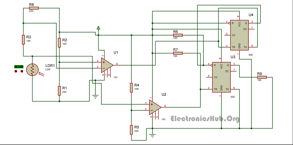
Unambiguous Night Lamp Switch Circuit Diagram
How to Operate this Night Lamp Switcher Circuit?
The circuit has two photo sensing devices which detect two levels of intensities. Light Dependant Resistors are used as photosensitive devices in this circuit. The light dependent resistor used with an op-amp as comparator detects the level of light intensity. The U1 IC 741 produces an output which is the first light intensity and the U2 IC741 detects the second light intensity. These two light intensities are used to calculate when the lights should be On and when they should be Off without producing unambiguous signals.
The two light detecting modules are arranged in such a way that when the first light intensity (dark point 1) is detected, the circuit turns On the relay and hence the lights will turn On. The circuit will turn Off the relay back again when both the light detecting modules detect light. This makes it eliminate ambiguities. There may be simpler circuits which detect darkness and turn On the lights but most of them fail to eliminate undesired repetitive switching. This circuit does a wonderful job by eliminating undesired switching effects.
The 555 IC U3 is in the bistable mode whereas the IC U4 acts as a buffer. The output of first IC 741 is given to the reset pin of the bistable IC whereas the output of second light detecting module with IC 741 is given to the set input of the bistable multivibrator.
This step-down converter drops AC mains voltage across Cac to produce a lower DC voltage .

another take on the transformerless AC line power supply, which finds use in some well-insulated, low-power devices. Our technical reviewer pointed out that Cac should be an X-rated safety type, and I think we'd both feel better if the ground symbol wasn't there!
SMPS circuits offer an efficient way to reduce AC from a mains source to any desired level for powering low-voltage circuits, though this comes at the cost of components such as control ICs, switching transistors, inductors, etc. Figure 1 shows a simple way you can use more common components to step-down and regulate the AC mains to the desired low DC voltage.
The reduction in AC voltage is obtained by dropping the unwanted extra voltage across a capacitor (impedance Z=1/?C) Cac of suitable value and voltage rating. The remaining AC is drawn as rectified output through a diode bridge. So even though DC flows through the output circuit of the bridge, the voltage dropping series capacitor Cac sees an AC flowing in its remaining part of the circuit.
The value of the capacitor determines the current output at reduced voltage. A larger capacitor is required for larger output currents. A bleeder resistor (1MO) is set in parallel with Cac to discharge it when the AC is disconnected. The DC after rectification and filtering is shunted by the Q1-based regulation circuit, which basically tries to maintain the output voltage within certain limits.
Figure 1 This step-down converter drops AC mains voltage across Cac to produce a lower DC voltage. VUZis optional and is related to safety issues – choose higher wattage if necessary. VU is the unregulated output which can be further regulated using chips like 7805/12 etc or a simple zener-transistor regulator. Q1 should be chosen according to power requirement – essentially it should be able to drain the unused current when the load is absent. The values/type of fuse are indicative – choose it according to your design/need.
The circuit has two LEDs. The red LED indicates whether the power from AC is being used, or bled as waste through Q1. The green LED indicates the power availability at the output where further regulating devices can be added.
R1, R2, and RB (R1,R2 » RB) form a voltage divider network which essentially monitors the
residual rectified AC from the bridge. Their values are chosen such that when the current is flowing through the load (not shown), Q1 is switched off and hence little current flows through the second bleeder resistor RB, limited by the large values of R1 and R2. The voltage drop across RB is not sufficient to turn on the red LED. At this point, we say the current flowing through R1, R2, and RB is the housekeeping current which constantly flows apart from the maximum load current.
Q1 is biased by the voltage drop across R2, which should be at least 0.6V for Q1 to turn on. During normal operation (current flowing through the load), the values of R1, R2, and RB are chosen such that this voltage is less than 0.6V. However, if the load is disconnected (no output current is being drawn) then the voltage after the diode bridge will increase, which in turn will increase the voltage drop across R2 until the transistor turns on and draws current through RB. This stops the voltage from increasing further, simultaneously increasing the current through the red LED. A glowing red LED indicates power wastage. However, the green LED always glows when power is available at the output. RB should be chosen such that the rise in voltage at the bridge output during no load condition is within the upper limit of any final regulator connected to +VU.
The required capacitor Cac is calculated as:

where IL is the maximum load current, Vrms is the RMS AC voltage, VE (~VU+1.2) is the residual expected voltage at the bridge input, which is taken to be the sum of VU and 1.2V across the bridge diodes. ?IL is the house keeping current apart from the maximum load current. A rough estimate of Cac is IL / (?Vrms) (where ? = 2pfAC) as can be seen from the formula by neglecting ?ILand VE, which are small compared to IL and Vrms respectively.
This circuit offers an alternative to a bulky, noisy, vibration/magnetic field/heat producing transformer. However, the advantage of the transformer is in the isolation it offers from live AC. The danger with the proposed circuit is when Cac shorts out. Precautions should be taken to see that the fuse blows out before the voltage across the output rises to a hazardous level. Under increased voltage conditions, extra current paths are offered by the zener VUZ and the filter capacitor CF . Additional cheap neon lamps can be added across the bridge input to salvage the output regulating circuit and the load.
In a test set up which was designed to obtain a zener-transistor regulated 4.8V supply at 5mA current: Cac=0.068µF, R1=10kO, R2=470O, RB=470O, CF=470µF, and Q1=BC549, with a 240V AC line. This power supply could power a 555 oscillator driving an LED. Another test used Cac=0.22µF, R1=10kO, R2=470O, RB=470O, CF=470µF, and Q1=BC549. This could be used to build a zener-transistor regulated power supply of 4.8V at 15mA current. It could easily power a 555 astable, a flashing LED, and a CD4518 counter driving eight LEDs.
It should be noted that the reactance of Cac is normally much higher than that of the power recipient circuit, and as such, the power supply behaves as if it is a constant current source. This type of power supply seems to be useful to power circuits with low current requirements, on the order of about 1mA to 100mA.
current-mode control-switching regulator


^
|
|
|

DE. WXO electronic circuit instrument control of A320 Air Bus to be Detector Tech


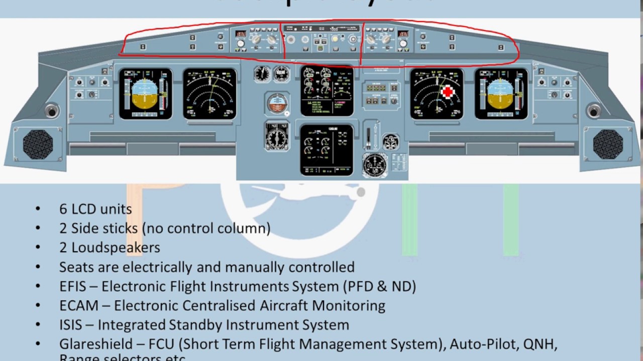

Electronic flight instrument system ( EFIS )
An electronic flight instrument system (EFIS) is a flight deck instrument display system that displays flight data electronically rather than electromechanically. An EFIS normally consists of a primary flight display (PFD), multi-function display (MFD), and an engine indicating and crew alerting system (EICAS) display. Early EFIS models used cathode ray tube (CRT) displays, but liquid crystal displays (LCD) are now more common. The complex electromechanical attitude director indicator (ADI) and horizontal situation indicator (HSI) were the first candidates for replacement by EFIS. Now, however, few flight deck instruments cannot be replaced by an electronic display.


Primary Flight Display
EFIS installations vary greatly. A light aircraft might be equipped with one display unit that displays flight and navigation data. A large, commercial aircraft is likely to have six or more display units. Typical EFIS displays and controls cab we look in this book . The equivalent electromechanical instruments are also shown here.
EFIS installation follows the sequence:
- Displays
- Controls
- Data processors
A basic EFIS might have all these facilities in the one unit.
Display units
Primary flight display (PFD)
On the flight deck, the display units are the most obvious parts of an EFIS system, and are the features that lead to the term glass cockpit. The display unit that replaces the ADI is called the primary flight display (PFD). If a separate display replaces the HSI, it is called the navigation display. The PFD displays all information critical to flight, including calibrated airspeed, altitude, heading, attitude, vertical speed and yaw. The PFD is designed to improve a pilot's situational awareness by integrating this information into a single display instead of six different analog instruments, reducing the amount of time necessary to monitor the instruments. PFDs also increase situational awareness by alerting the aircrew to unusual or potentially hazardous conditions — for example, low airspeed, high rate of descent — by changing the color or shape of the display or by providing audio alerts.
The names Electronic Attitude Director Indicator and Electronic Horizontal Situation Indicator are used by some manufacturers.[1] However, a simulated ADI is only the centerpiece of the PFD. Additional information is both superimposed on and arranged around this graphic.
Multi-function displays can render a separate navigation display unnecessary. Another option is to use one large screen to show both the PFD and navigation display.
The PFD and navigation display (and multi-function display, where fitted) are often physically identical. The information displayed is determined by the system interfaces where the display units are fitted. Thus, spares holding is simplified: the one display unit can be fitted in any position.
LCD units generate less heat than CRTs; an advantage in a congested instrument panel. They are also lighter, and occupy a lower volume.
Multi-function display (MFD)
_on_Boeing_747-400.jpg)
The MFD (multi-function display) displays navigational and weather information from multiple systems. MFDs are most frequently designed as "chart-centric", where the aircrew can overlay different information over a map or chart. Examples of MFD overlay information include the aircraft's current route plan, weather information from either on-board radar or lightning detection sensors or ground-based sensors, e.g., NEXRAD, restricted airspace and aircraft traffic. The MFD can also be used to view other non-overlay type of data (e.g., current route plan) and calculated overlay-type data, e.g., the glide radius of the aircraft, given current location over terrain, winds, and aircraft speed and altitude.
MFDs can also display information about aircraft systems, such as fuel and electrical systems (see EICAS, below). As with the PFD, the MFD can change the color or shape of the data to alert the aircrew to hazardous situations.
Engine indications and crew alerting system (EICAS) / electronic centralized aircraft monitoring (ECAM)
EICAS (Engine Indications and Crew Alerting System) displays information about the aircraft's systems, including its fuel, electrical and propulsion systems (engines). EICAS displays are often designed to mimic traditional round gauges while also supplying digital readouts of the parameters.
EICAS improves situational awareness by allowing the aircrew to view complex information in a graphical format and also by alerting the crew to unusual or hazardous situations. For example, if an engine begins to lose oil pressure, the EICAS might sound an alert, switch the display to the page with the oil system information and outline the low oil pressure data with a red box. Unlike traditional round gauges, many levels of warnings and alarms can be set. Proper care must be taken when designing EICAS to ensure that the aircrew are always provided with the most important information and not overloaded with warnings or alarms.
ECAM is a similar system used by Airbus, which in addition to providing EICAS functions also recommend remedial action.
Control panels

EICAS after landing, showing outside air temperature, N1 RPM, exhaust gas temperature, N2 RPM, Fuel Flow/Fuel Used indications, fuel on the tanks, oil pressure, oil temperature, oil quantity, engine vibration, hydraulic pressure and hydraulic quantity.
EFIS provides pilots with controls that select display range and mode (for example, map or compass rose) and enter data (such as selected heading).
Where other equipment uses pilot inputs, data buses broadcast the pilot's selections so that the pilot need only enter the selection once. For example, the pilot selects the desired level-off altitude on a control unit. The EFIS repeats this selected altitude on the PFD, and by comparing it with the actual altitude (from the air data computer) generates an altitude error display. This same altitude selection is used by the automatic flight control system to level off, and by the altitude alerting system to provide appropriate warnings.
Data processors
The EFIS visual display is produced by the symbol generator. This receives data inputs from the pilot, signals from sensors, and EFIS format selections made by the pilot. The symbol generator can go by other names, such as display processing computer, display electronics unit, etc.
The symbol generator does more than generate symbols. It has (at the least) monitoring facilities, a graphics generator and a display driver. Inputs from sensors and controls arrive via data buses, and are checked for validity. The required computations are performed, and the graphics generator and display driver produce the inputs to the display units.
Capabilities
Like personal computers, flight instrument systems need power-on-self-test facilities and continuous self-monitoring. Flight instrument systems, however, need additional monitoring capabilities:
- Input validation — verify that each sensor is providing valid data
- Data comparison — cross check inputs from duplicated sensors
- Display monitoring — detect failures within the instrument system
Former practice
Traditional (electromechanical) displays are equipped with synchro mechanisms that transmit the pitch, roll, and heading shown on the captain and first officer's instruments to an instrument comparator. The comparator warns of excessive differences between the Captain and First Officer displays. Even a fault as far downstream as a jam in, say, the roll mechanism of an ADI triggers a comparator warning. The instrument comparator thus provides both comparator monitoring and display monitoring.
Comparator monitoring
With EFIS, the comparator function is simple: Is roll data (bank angle) from sensor 1 the same as roll data from sensor 2? If not, display a warning caption (such as CHECK ROLL) on both PFDs. Comparison monitors give warnings for airspeed, pitch, roll, and altitude indications. More advanced EFIS systems have more comparator monitors.
Display monitoring
In this technique, each symbol generator contains two display monitoring channels. One channel, the internal, samples the output from its own symbol generator to the display unit and computes, for example, what roll attitude should produce that indication. This computed roll attitude is then compared with the roll attitude input to the symbol generator from the INS or AHRS. Any difference has probably been introduced by faulty processing, and triggers a warning on the relevant display.
The external monitoring channel carries out the same check on the symbol generator on the other side of the flight deck: the Captain's symbol generator checks the First Officer's, the First Officer's checks the Captain's. Whichever symbol generator detects a fault, puts up a warning on its own display.
The external monitoring channel also checks sensor inputs (to the symbol generator) for reasonableness. A spurious input, such as a radio height greater than the radio altimeter's maximum, results in a warning.
Human factors
Clutter
At various stages of a flight, a pilot needs different combinations of data. Ideally, the avionics only show the data in use—but an electromechanical instrument must be in view all the time. To improve display clarity, ADIs and HSIs use intricate mechanisms to remove superfluous indications temporarily—e.g., removing the glide slope scale when the pilot doesn't need it.
Under normal conditions, an EFIS might not display some indications, e.g., engine vibration. Only when some parameter exceeds its limits does the system display the reading. In similar fashion, EFIS is programmed to show the glideslope scale and pointer only during an ILSapproach.
In the case of an input failure, an electromechanical instrument adds yet another indicator—typically, a bar drops across the erroneous data. EFIS, on the other hand, removes invalid data from the display and substitutes an appropriate warning.
A de-clutter mode activates automatically when circumstances require the pilot's attention for a specific item. For example, if the aircraft pitches up or down beyond a specified limit—usually 30 to 60 degrees—the attitude indicator de-clutters other items from sight until the pilot brings the pitch to an acceptable level. This helps the pilot focus on the most important tasks.
Color
Traditional instruments have long used color, but lack the ability to change a color to indicate some change in condition. The electronic display technology of EFIS has no such restriction and uses color widely. For example, as an aircraft approaches the glide slope, a blue caption can indicate glide slope is armed, and capture might change the color to green. Typical EFIS systems color code the navigation needles to reflect the type of navigation. Green needles indicate ground based navigation, such as VORs, Localizers and ILS systems. Magenta needles indicate GPS navigation.
Advantages
EFIS provides versatility by avoiding some physical limitations of traditional instruments. A pilot can switch the same display that shows a course deviation indicator to show the planned track provided by an area navigation or flight management system. Pilots can choose to superimpose the weather radar picture on the displayed route.
The flexibility afforded by software modifications minimises the costs of responding to new aircraft regulations and equipment. Software updates can update an EFIS system to extend its capabilities. Updates introduced in the 1990s included the ground proximity warning system, and traffic collision avoidance system.
A degree of redundancy is available even with the simple two-screen EFIS installation. Should the PFD fail, transfer switching repositions its vital information to the screen normally occupied by the navigation display.
Advances in EFIS
In the late 1980s, EFIS became standard equipment on most Boeing and Airbus airliners, and many business aircraft adopted EFIS in the 1990s.
Recent advances in computing power and reductions in the cost of liquid-crystal displays and navigational sensors (such as GPS and attitude and heading reference system) have brought EFIS to general aviation aircraft. Notable examples are the Garmin G1000 and Chelton Flight Systems EFIS-SV.
Several EFIS manufacturers have focused on the experimental aircraft market, producing EFIS and EICAS systems for as little as US$1,000-2000. The low cost is possible because of steep drops in the price of sensors and displays, and equipment for experimental aircraft doesn't require expensive Federal Aviation Administration certification. This latter point restricts their use to experimental aircraft and certain other aircraft categories, depending on local regulations. Uncertified EFIS systems are also found in Sport Pilot category aircraft, including factory built, microlight, and ultralight aircraft. These systems can be fitted to certified aircraft in some cases as secondary or backup systems depending on local aviation rules.
Acronyms and abbreviations in avionics
A
- A/A: Air to air TACAN function
- A/P: Autopilot
- ABAS: Aircraft-based augmentation system
- ACARS: Aircraft communications addressing and reporting system
- ACAS: Airborne collision avoidance system
- ACC: Area control centre
- ACE: Actuator control electronics
- ACMS: Aircraft condition monitoring system
- ACP: Audio control panel
- ACR: Avionic Communication Router
- ACS: Audio control system
- ADAHRS: Air data and attitude heading reference system
- ADC: Air data computer
- ADF: Automatic direction finder
- ADI: Attitude director indicator
- ADIRS: Air data inertial reference system
- ADIRU: Air data inertial reference unit
- ADM: Air data module
- ADS: Either; automatic dependent surveillance or air data system
- ADS-A: Automatic dependent surveillance – address
- ADS-B: Automatic dependent surveillance – broadcast
- ADS-C: Automatic dependent surveillance – contract
- AESA: Active electronically scanned array
- AFCS: Automatic flight control system
- AFD: Autopilot flight director
- AFDC: Autopilot flight director computer
- AFDS: Autopilot flight director system
- AFDX Avionics Full-Duplex Switched Ethernet
- AFIS: Either: Automatic flight information service or airborne flight information system
- AGACS: Automatic ground–air communications system, is also known as ATCSS or data link
- AGC: Automatic gain control
- AGDL: Air–ground data link
- AHC: Attitude heading control
- AHRS: Attitude and heading reference system
- AHRU: Attitude and heading reference unit
- AIDS: Aircraft integrated data system
- AIXM: Aeronautical information exchange model
- ALC: Automatic level control
- ALT: Either; altimeter or altitude
- ALT hold: Altitude hold mode
- ALTS: Altitude select
- AMLCD: Active-matrix liquid crystal display
- AMO: Approved maintenance organisation
- AMS: Air management system
- ANC: Active noise cancellation
- ANN: Annunciator – caution warning system normally containing visual and audio alerts to the pilot
- ANR: Active noise reduction
- ANT: Antenna
- AOC: Aeronautical operational control
- AOP: Airport operating plan
- APARS: Automatic pressure altitude reporting system
- APIRS: Attitude and positioning inertial reference system
- APOA: Airport of arrival
- APC: Auto pilot computer
- APOD: Airport of departure
- APM: Aircraft personality module
- APS: Auto pilot system
- APU: Auxiliary power unit
- ARINC: Aeronautical Radio, Incorporated
- ASD: Aircraft situation display
- ASDL: Aeronautical satellite data link
- ASR: Airport surveillance radar
- ASU: Avionics switching unit
- AT: Auto throttle
- ATC: Air traffic control
- ATCC: Air traffic control centre
- ATCT: Airport traffic control tower
- ATCRBS: Air traffic control radar beacon system
- ATCSS: Air traffic control signalling system
- ATIS: Automated terminal information service
- ATR: Air transportable racking
- ATR: Automatic thrust restoration
- ATSAW: Airborne traffic situational awareness
- ATSU: Air traffic services unit
- ATT: Attitude
- Avionics: Aviation electronics
- AWOS: Automated weather observation system
- AWACS: Advanced warning and control systems
- ALNA: Airline network architecture
B
- B RNAV: Basic area navigation
- BARO: Barometric indication, setting or pressure
- BITE: Built-in test equipment
- BCRS: Back course
- BDI: Bearing distance indicator
- BGAN: Broadcast Global Area Network
- BER: Beyond economic repair
C
- CACTCS: Cabin Air Conditioning and Temperature Control System (pronounced "Cactus")
- CAI: Caution annunciator indicator
- CAS: Calibrated airspeed
- CAT I: Operational performance Category 1
- CAT I Enhanced Allows for lower minimums than CAT I in some cases to CAT 2 minimums
- CAT II: Operational performance Category II
- CAT IIIa: Operational performance Category IIIa
- CAT IIIb: Operational performance Category IIIb
- CAT IIIc: Operational performance Category IIIc
- CB: Cumulonimbus cloud
- CDA: Continuous descent approach
- CDCCL: Critical Design Configuration Control Limitations
- CDI: Course deviation indicator
- CDTI: Cockpit display of traffic information
- CFIT: Controlled flight into terrain
- CHP: Course Heading Panel
- CHT: Cylinder Head Temperature
- CMU: Communications Management Unit
- CNS: Communication, navigation and surveillance
- CNS/ATM: Communication, navigation and surveillance / Air traffic management[1]
- CODEC: Coder/decoder
- COMM or COM: Communications transceiver, Communications receiver, or Communications radio transmitter (now, normally: either VHF or UHF; HF communications avionics are usually abbreviated simply HF)
- COTS: Commercial off-the-shelf
- CPDLC: Controller–pilot data link communications
- CPS: Cycles per second
- CRT: Cathode ray tube
- CTAF: Common traffic advisory frequency
- CV/DFDR: Cockpit voice and digital flight data recorder
- CVR: Cockpit voice recorder
- CWS: Control wheel steering
D
- DA: Decision altitude
- DA: Drift angle
- DAPs: Downlink of aircraft parameters
- DCDU: Data link control and display unit
- DCL: Departure Clearance via CPDLC
- DCP: Display control panel
- DFDR: Digital Flight Data Recorder
- DFMC: Dual Frequency Multiple Constellation
- DG: Directional gyroscope
- DGPS: Differential global positioning system
- DH: Decision height
- DLR: Data link recorder
- DME: Distance measuring equipment
- DNC: Direct noise canceling
- DP: Departure procedures
- DPU: Display Processor Unit
- DSP: Digital signal processing
- DTU: Data transfer unit
- DUAT: Direct user access terminal
- DVE: Degraded Visual Environment
- DRMC : Direct Reading Magnetic Compass .
E
- EADI: Electronic attitude director indicator
- ECU: Engine Control Unit (=EEC)
- EEC: Electronic Engine Control
- EFD: Electronic flight display
- EFIS: Electronic flight instrument system
- EGI: Embedded GPS Inertial
- EGNOS: European Geostationary Navigation Overlay Service
- EGPWS: Enhanced ground proximity warning system
- EGT: Exhaust gas temperature
- EHS: Enhanced surveillance
- EHSI: Electronic horizontal situation indicator
- EICAS: Engine indication crew alerting system
- ELT: Emergency locator transmitter
- ENC: Electronic noise canceling
- ENG: Engine
- ENR: Electronic noise reduction
- EPR: Engine pressure ratio
- EPU: Emergency Power Unit
- ERAM: En Route Automation Modernization
- ETOP(S): Extended-range twin-engine operation(s)
F
- FAA: Federal Aviation Administration
- FADEC: Full authority digital engine control
- FAF: Final approach fix
- FANS: Future Air Navigation System
- FAT: Free air temperature
- FBO: Fixed Base Operator
- FBW: Fly-by-wire
- FCC: Flight Control Computer
- FCMC: Fuel Control & Monitoring Computer
- FCS: Flight Control System
- FD: Flight Director
- FDAU: Flight-data acquisition unit
- FDPS: Flight plan Data Processing System
- FDR: Flight Data Recorder
- FDRS: Flight data recorder system
- FDU: Flux detector unit
- FF: Fuel flow
- FG: Flight Guidance
- FIC: Flight Information Centre
- FIS-B: Flight information services – broadcast
- FLIR: Forward-looking infra-red
- FLTA: Forward-looking terrain avoidance
- FMA: Flight Mode Annunciator
- FMGS: Flight Management & Guidance System
- FMS: Flight management system
- FOB: Fuel On-Board
- FQIS: Fuel Quantity Indication System
- FREQ: Frequency
- FSS: Flight service station
- FWS: Flight warning system
- FYDS: Flight director/ Yaw damper system
G
- GA: Go Around
- GAST: GBAS Approach Service Type
- GBAS: Ground based augmentation system
- GCAS: Ground collision avoidance system
- GCU: Generator control unit
- GDOP: Geometric dilution of precision
- GGS: Global positioning system ground station
- GHz: Gigahertz
- GLNS: GPS Landing and Navigation System
- GLNU: GPS landing and navigation unit
- GLONASS: Global Navigation Satellite System
- GLS: GBAS Landing System
- GLU: GPS landing unit
- GMT: Greenwich Mean Time
- GND: Ground
- GNSS: Global Navigation Satellite System
- GO: Go Around
- GPS: Global Positioning System
- GPWC: Ground proximity warning computer
- GPWS: Ground proximity warning system
- G/S: Glide Slope
- GS: Ground speed
H
- "Hg: Symbol for unit of pressure, Inch of Mercury
- HDG: Heading
- HDG SEL: Heading select
- HDOP: Horizontal dilution of precision
- HF: High frequency
- HHLD: Heading hold
- HIRF: High intensity radiated field
- HMD: Helmet-mounted display
- HPR: High Pressure Rotor
- HSD: High-speed data
- HSI: Horizontal situation indicator
- HSL: Heading select
- HUMS: Health and usage monitoring systems
- HUD: Head-up display
- Hz: Symbol for unit of frequency, Hertz
I
- IAP: Instrument approach procedure
- IAS: Indicated airspeed
- ID: Identify/Identification or identifier
- IDENT: Identify/identifier
- IDS: Information display system or integrated display system
- IFE: In-flight entertainment
- IFF: Identification Friend or Foe
- IFICS: [(Integrated Flight Instrument and Control System)][2]
- IFR: Instrument Flight Rules
- ILS: Instrument landing system
- IMC: Instrument meteorological conditions
- IND: Indicator
- InHg: Inch of Mercury
- INS: Inertial Navigation System
- IRS: Inertial Reference System
- IRU: Inertial reference unit
- ISA: International Standard Atmosphere
- ISP: Integrated switching panel
- ISIS: Integrated standby instrument system
- ITT: Interstage turbine temperature
- IVSI: Instantaneous vertical speed indicator
J
K
- KIAS: Knots Indicated airspeed
- KTAS: Knots true airspeed
L
- LAAS: Local Area Augmentation System
- LADGPS: Local Area Differential GPS
- LCD: Liquid crystal display
- LDGPS: Local area differential global positioning satellite
- LED: Light-emitting diode
- LMM: Locator middle marker
- LOC: Localizer
- LOM: Locator outer marker
- LOPA: Location of Passenger Accommodations
- LORAN: Long-range navigation
- LPR: Low Pressure Rotor
- LPV: Localizer performance with vertical guidance
- LRU: Line-replaceable unit
- LTE: Loss of Tail Rotor Effectiveness Helicopters
- LVP: Low visibility procedures, a designated state of operations at aerodromes where instrument approaches and low visibility takeoff procedures are using during inclement weather
- LX: Lightning
M
- MAP: Manifold absolute pressure or missed approach point
- MAPS: Minimum Aviation Performance Standards
- MB: Marker beacon
- MCBF: Mean cycles between failures
- MCDU: Multi-purpose/Multi-function Control and Display Unit
- MDA: Minimum descent altitude
- MEA: Minimum en-route altitude
- MEL: Minimum equipment list
- METAR: Meteorological Aerodrome Report
- MCP: Mode control panel
- MF: Medium frequency
- MFD: Multi-function display
- MFDS: Multi-function display system
- MIC: Microphone
- MIDS: Multifunctional information distribution system
- MILSPEC: Military specification
- MKP: Multi-function Keypad
- MKR: Marker beacon
- MLS: Microwave landing system
- MM: Middle marker
- MMD: Moving map display
- MNPS: Minimum navigation performance specifications
- MOA: Military operations area
- Mode A: Transponder pulse-code reporting
- Mode C: Transponder code and altitude reporting
- Mode S: Transponder code, altitude, and TCAS reporting
- MOPS: Minimum Operational Performance Standard
- MORA: Minimum Off Route Altitude
- MOSArt: Modular Open System Architecture
- MPU: Multifunction Processor Unit
- MSA: Minimum safe altitude
- MSG: Message
- MSP: Modes S-Specific Protocol
- MSSS: Mode S-Specific Services
- MTBF: Mean time between failures
- MTBUR: Mean time between unscheduled removals
- MTTF: Mean time to failure
- MVA: Minimum vectoring altitude
- MVFR: Marginal visual flight rules
- MZFW: Maximum Zero Fuel Weight
N
- N1: Low Pressure rotor (spool) speed (see Jet engine)
- N2: High Pressure rotor (spool) speed (see Jet engine)
- NAS: National Airspace System
- NAV: Navigation receiver (normally VHF navigation receiver for VOR system.)
- Navaid: Navigational aid
- NAVCOMM, NAV/COM or NAV-COM: Combination navigation and communications equipment (normally VHF navigation receiver integrated with VHF communications transceiver).
- NAVSTAR-GPS: NAVigation Satellite Timing And Ranging (The formal name for the space-borne or satellite navigation system)
- NCAT: National Center for Aviation Training
- NCATT: National Center for Aircraft Technician Training
- ND: Navigation display
- NDB: Non-directional radio beacon
- NFF: No fault found
- NGS: Nitrogen Generation System, found in aircraft to reduce fire risk in fuel tanks.
- NM or NMI: Nautical mile
- NORDO: No radio
- NoTAM: Notice to Airmen
- NPA: Non-precision approach
- NVD: Night vision device
- NVG: Night vision goggles
O
- OAT: Outside air temperature
- OBS: Omnibearing selector
- OCC: Operations control center
- OCH: Obstacle Clearance Height
- OM: Outer marker
- OWE/OEW: Operating Weight Empty/Operating empty weight
P
- PA: Public address system
- PAEW: Personnel and equipment working
- PAL: Pilot Activated Lighting
- PAPI: Precision approach path indicator
- PAR: Precision approach radar
- PCL: Pilot Controlled Lighting
- P-Code: GPS precision code
- PD: Profile descent
- PDC: Pre-Departure Clearance
- PDOP: Position dilution of precision
- PESA: Passive electronically scanned array
- PFD: Primary flight display or primary flight director
- PMG: Permanent magnet generator
- PND: Primary navigation display
- PNR: Passive noise reduction
- POF: Phase of flight
- POH: Pilot's Operating Handbook
- POS: Position
- P-RNAV: precision area navigation
- PRA: Pre-recorded announcement
- PSR: Primary surveillance radar
- PSU: Passenger service unit
- PTT: Push-to-talk
Q
- QAR: Quick Access Recorder
- QNH: Barometric pressure adjusted to sea level
- QRH: Quick Reference Handbook
R
- RA: Resolution advisory (TCAS)
- Rad Alt: Radio Altitude
- Radar: RAdio Detection And Ranging
- RAI: Radio altimeter indicator
- RAIM: Receiver-autonomous integrity monitoring, also remote autonomous integrity monitoring
- RALT: Radar or radio altimeter
- RAT: Ram air turbine
- RCR: Reverse current relay
- RCVR: Receiver
- RDMI: Radio distance magnetic indicator
- RDP: Radar data processing system
- RDR: Radar
- REF: Reference
- REIL: Runway end identifier lights
- REL: Relative
- RF: Radio frequency
- RFI: Radio frequency interference
- RHSM: Reduced horizontal separation minimal
- RLG: Ring laser gyroscope
- RLY: Relay
- RMI: Radio magnetic indicator
- R-NAV: Area navigation
- RNG: Range
- RNP: Required navigation performance
- ROC: Rate of climb
- ROD: Rate of descent
- RPA: Remotely piloted aircraft (Unmanned aerial vehicle)
- RPM: Revolutions per minute
- RSP: Reversion switch panel
- RTE: Route
- RVR: Runway visual range
- RVSM: Reduced vertical separation minimum
- RX: Receiver
S
- SAR: Search and Rescue, Smart ACMS Recorder
- SAT: Static air temperature
- SATCOM: Satellite communication
- SATNAV: Satellite navigation
- SD: Secure digital
- SDF: Simplified directional facility
- SDU: Satellite data unit
- SELCAL: Selective calling
- SID: Standard instrument departure
- SIU: Satellite interface unit
- SMS: Short Messaging Service
- SNR: Signal-to-noise ratio
- SPKR: Speaker
- SQ or SQL: Squelch
- SRS: Speed Reference System
- SSCV/DR: Solid-state cockpit voice/data recorder
- SSCVR: Solid-state cockpit voice recorder
- SSFDR: Solid-state flight data recorder
- SSR: Secondary surveillance radar
- STAR: Standard terminal arrival route
- STARS: Standard Terminal Automation Replacement System
- STC: Supplemental Type Certificate
- STCA: Short-Term Conflict Alert
- STP: Standard temperature and pressure
- SUA: Special use airspace
T
- TA: Traffic advisory (see TCAS)
- TACAN: Tactical air navigation system
- Tach: Tachometer
- TAD: Terrain awareness display
- TAF: Terminal area forecast
- TAS: True airspeed
- TAT: True air temperature, or total air temperature
- TAWS: Terrain awareness and warning system
- TBO: Time before overhaul, or time between overhaul
- TCA: Throttle control assembly, or terminal control area
- TCAS: Traffic collision avoidance system
- TCF: Terrain clearance floor
- TCN: TACAN
- TCU: TACAN control unit
- TDOP: Time dilution of precision
- TDR: Transponder (in some cases)
- TERPS: Terminal instrument procedures, or terminal en route procedures
- TFR: Temporary flight restrictions
- TFT: Thin-film transistor
- TGT: Turbine gas temperature, or target
- THDG: True heading
- TIS: Traffic information service
- TIT: Turbine Inlet Temperature
- TK: Track angle
- TKE: Track-angle error
- TLA: Thrust Lever Angle
- TLA: Three-letter acronym
- TOC: Top of climb
- TOD: Top of Descent point
- TOGA or TO/GA: Takeoff/Go-around switch, Takeoff/go-around thrust
- TOT: Turbine outlet temperature
- TR or T/R: Transmitter receiver or transceiver
- T/R: Thrust Reverser or Tail Rotor
- TRACON: Terminal radar approach control
- TRANS: Transmit, Transmission, or Transition
- TRK: Track
- TRP: Mode S transponder
- TTL: Tuned to Localizer
- TTR: TCAS II transmitter/receiver
- TTS: Time to station
- TVE: Total vertical error
- TWDL: Two-way data link, or terminal weather data link
- TWDR: Terminal Doppler Weather Radar
- TWIP: Terminal weather information for pilots
- TWR: Terminal weather radar
- Twr: Tower (Aerodrome Control)
- TX: Transmit
U
- UAC: Upper Area Control
- UART: Universal asynchronous receiver transmitter
- UAV: Unmanned aerial vehicle
- UHF: Ultra-high frequency
- ULB: Underwater locator beacon
- USB: Universal Serial Bus
- UTC: Universal Time Coordinate
V
- V: Volts or voltage
- V/L: VOR/Localizer
- V/NAV: Vertical navigation
- V/R: Voltage regulator
- V/REF: Reference velocity
- V/S: Vertical speed
- V/TRK: Vertical track
- VASI: Visual approach slope indicator
- VASIS: Visual approach slope indicator (system)
- VDF: VHF Direction Finding
- VDL: VHF Data Link
- VDR: VHF digital radio
- VFO: Variable frequency oscillator
- VFR: Visual flight rules
- VG/DG: Vertical gyroscope/directional gyroscope
- VGA: Video Graphics Array
- VHF: Very high frequency
- VMC: Visual meteorological conditions or minimum control speed with critical engine out
- VNE: Never exceed speed
- VNO: Maximum structural cruising speed
- VNR: VHF navigation receiver
- VOR: VHF omnidirectional range and ranging
- VOR/DME: VOR with Distance measuring equipment
- VOR/MB: VOR marker beacon
- VORTAC: VOR and TACAN combination
- VOX: Voice transmission
- VPA: Vertical Path Approach
- VPATH: Vertical path
- VRP: Visual Point of Reference
- VSI: Vertical speed indicator
- VSM: Vertical separation limit
- VSO: Stall speed in landing configuration
- VSWR: Voltage–standing wave ratio
- VX: Speed for best angle of climb
- VY: Speed for best rate of climb
W
- WAAS: Wide Area Augmentation System
- WD: Wind direction
- WINDR: Wind direction
- WMA: WXR waveguide adapter
- WMI: WXR indicator mount
- WMS: Wide-area master station
- WMSC: Weather message switching center
- WMSCR: Weather message switching center replacement
- WPT: Waypoint
- WRT: WXR receiver transmitter
- WS: Wind shear
- WX: Weather
- WXR: Weather radar system
- WYPT: Waypoint
X
- XCVR: Transceiver
- XFR: Transfer
- XMIT: Transmit
- XMSN: Transmission
- XMTR: Transmitter
- XPDR: Transponder
- XTK: Crosstrack
- X-Start: Cross-start. Use the air pressure or electrical power from a working engine.
Y
- YD: Yaw damper
- Y : YAW
Z
- ZFW: Zero Fuel Weight
Avionics
Avionics are the electronic systems used on aircraft, artificial satellites, and spacecraft. Avionic systems include communications, navigation, the display and management of multiple systems, and the hundreds of systems that are fitted to aircraft to perform individual functions. These can be as simple as a searchlight for a police helicopter or as complicated as the tactical system for an airborne early warning platform. The term avionics is a portmanteau of the words aviation and electronics.

example of Radar and other avionics in the nose of a Cessna Citation I/SP.

F‑105 Thunderchief with avionics laid out
The term "avionics" was coined by the journalist Philip J. Klass as a portmanteau of "aviation electronics". Many modern avionics have their origins in World War II wartime developments. For example, autopilot systems that are commonplace today began as specialized systems to help bomber planes fly steadily enough to hit precision targets from high altitudes. Famously, radar was developed in the UK, Germany, and the United States during the same period. Modern avionics is a substantial portion of military aircraft spending. Aircraft like the F‑15E and the now retired F‑14 have roughly 20 percent of their budget spent on avionics. Most modern helicopters now have budget splits of 60/40 in favour of avionics.
The civilian market has also seen a growth in cost of avionics. Flight control systems (fly-by-wire) and new navigation needs brought on by tighter airspaces, have pushed up development costs. The major change has been the recent boom in consumer flying. As more people begin to use planes as their primary method of transportation, more elaborate methods of controlling aircraft safely in these high restrictive airspaces have been invented.
Modern avionics
Avionics plays a heavy role in modernization initiatives like the Federal Aviation Administration's (FAA) Next Generation Air Transportation System project in the United States and the Single European Sky ATM Research (SESAR) initiative in Europe. The Joint Planning and Development Office put forth a roadmap for avionics in six areas:
- Published Routes and Procedures – Improved navigation and routing
- Negotiated Trajectories – Adding data communications to create preferred routes dynamically
- Delegated Separation – Enhanced situational awareness in the air and on the ground
- LowVisibility/CeilingApproach/Departure – Allowing operations with weather constraints with less ground infrastructure
- Surface Operations – To increase safety in approach and departure
- ATM Efficiencies – Improving the ATM process
Aircraft avionics
The cockpit of an aircraft is a typical location for avionic equipment, including control, monitoring, communication, navigation, weather, and anti-collision systems. The majority of aircraft power their avionics using 14- or 28‑volt DC electrical systems; however, larger, more sophisticated aircraft (such as airliners or military combat aircraft) have AC systems operating at 400 Hz, 115 volts AC. There are several major vendors of flight avionics, including Panasonic Avionics Corporation, Honeywell (which now owns Bendix/King), Universal Avionics Systems Corporation, Rockwell Collins (now Collins Aerospace), Thales Group, GE Aviation Systems, Garmin, Raytheon, Parker Hannifin, UTC Aerospace Systems and Avidyne Corporation.
International standards for avionics equipment are prepared by the Airlines Electronic Engineering Committee (AEEC) and published by ARINC.
Communications
Communications connect the flight deck to the ground and the flight deck to the passengers. On‑board communications are provided by public-address systems and aircraft intercoms.
The VHF aviation communication system works on the airband of 118.000 MHz to 136.975 MHz. Each channel is spaced from the adjacent ones by 8.33 kHz in Europe, 25 kHz elsewhere. VHF is also used for line of sight communication such as aircraft-to-aircraft and aircraft-to-ATC. Amplitude modulation (AM) is used, and the conversation is performed in simplex mode. Aircraft communication can also take place using HF (especially for trans-oceanic flights) or satellite communication.
Air navigation is the determination of position and direction on or above the surface of the Earth. Avionics can use satellite navigation systems (such as GPS and WAAS), INS( inertial navigation system), ground-based radio navigation systems (such as VOR or LORAN), or any combination thereof. Navigation systems calculate the position automatically and display it to the flight crew on moving map displays. Older avionics required a pilot or navigator to plot the intersection of signals on a paper map to determine an aircraft's location; modern systems calculate the position automatically and display it to the flight crew on moving map displays.
Monitoring

The first hints of glass cockpits emerged in the 1970s when flight-worthy cathode ray tube (CRT) screens began to replace electromechanical displays, gauges and instruments. A "glass" cockpit refers to the use of computer monitors instead of gauges and other analog displays. Aircraft were getting progressively more displays, dials and information dashboards that eventually competed for space and pilot attention. In the 1970s, the average aircraft had more than 100 cockpit instruments and controls.
Glass cockpits started to come into being with the Gulfstream G‑IV private jet in 1985. One of the key challenges in glass cockpits is to balance how much control is automated and how much the pilot should do manually. Generally they try to automate flight operations while keeping the pilot constantly informed.
Aircraft flight-control system
Aircraft have means of automatically controlling flight. Autopilot was first invented by Lawrence Sperry during World War I to fly bomber planes steady enough to hit accurate targets from 25,000 feet. When it was first adopted by the U.S. military, a Honeywell engineer sat in the back seat with bolt cutters to disconnect the autopilot in case of emergency. Nowadays most commercial planes are equipped with aircraft flight control systems in order to reduce pilot error and workload at landing or takeoff.
The first simple commercial auto-pilots were used to control heading and altitude and had limited authority on things like thrust and flight control surfaces. In helicopters, auto-stabilization was used in a similar way. The first systems were electromechanical. The advent of fly by wire and electro-actuated flight surfaces (rather than the traditional hydraulic) has increased safety. As with displays and instruments, critical devices that were electro-mechanical had a finite life. With safety critical systems, the software is very strictly tested.
Collision-avoidance systems
To supplement air traffic control, most large transport aircraft and many smaller ones use a traffic alert and collision avoidance system (TCAS), which can detect the location of nearby aircraft, and provide instructions for avoiding a midair collision. Smaller aircraft may use simpler traffic alerting systems such as TPAS, which are passive (they do not actively interrogate the transponders of other aircraft) and do not provide advisories for conflict resolution.
To help avoid controlled flight into terrain (CFIT), aircraft use systems such as ground-proximity warning systems (GPWS), which use radar altimeters as a key element. One of the major weaknesses of GPWS is the lack of "look-ahead" information, because it only provides altitude above terrain "look-down". In order to overcome this weakness, modern aircraft use a terrain awareness warning system (TAWS).
Flight recorders
Commercial aircraft cockpit data recorders, commonly known as "black boxes", store flight information and audio from the cockpit. They are often recovered from an aircraft after a crash to determine control settings and other parameters during the incident.
Weather systems
Weather systems such as weather radar (typically Arinc 708 on commercial aircraft) and lightning detectors are important for aircraft flying at night or in instrument meteorological conditions, where it is not possible for pilots to see the weather ahead. Heavy precipitation (as sensed by radar) or severe turbulence (as sensed by lightning activity) are both indications of strong convective activity and severe turbulence, and weather systems allow pilots to deviate around these areas.
Lightning detectors like the Stormscope or Strikefinder have become inexpensive enough that they are practical for light aircraft. In addition to radar and lightning detection, observations and extended radar pictures (such as NEXRAD) are now available through satellite data connections, allowing pilots to see weather conditions far beyond the range of their own in-flight systems. Modern displays allow weather information to be integrated with moving maps, terrain, and traffic onto a single screen, greatly simplifying navigation.
Modern weather systems also include wind shear and turbulence detection and terrain and traffic warning systems.[9] In‑plane weather avionics are especially popular in Africa, India, and other countries where air-travel is a growing market, but ground support is not as well developed.
Aircraft management systems
There has been a progression towards centralized control of the multiple complex systems fitted to aircraft, including engine monitoring and management. Health and usage monitoring systems (HUMS) are integrated with aircraft management computers to give maintainers early warnings of parts that will need replacement.
The integrated modular avionics concept proposes an integrated architecture with application software portable across an assembly of common hardware modules. It has been used in fourth generation jet fighters and the latest generation of airliners.
Mission or tactical avionics
Military aircraft have been designed either to deliver a weapon or to be the eyes and ears of other weapon systems. The vast array of sensors available to the military is used for whatever tactical means required. As with aircraft management, the bigger sensor platforms (like the E‑3D, JSTARS, ASTOR, Nimrod MRA4, Merlin HM Mk 1) have mission-management computers.
Police and EMS aircraft also carry sophisticated tactical sensors.
Military communications
While aircraft communications provide the backbone for safe flight, the tactical systems are designed to withstand the rigors of the battle field. UHF, VHF Tactical (30–88 MHz) and SatCom systems combined with ECCM methods, and cryptography secure the communications. Data links such as Link 11, 16, 22 and BOWMAN, JTRS and even TETRAprovide the means of transmitting data (such as images, targeting information etc.).
Radar
Airborne radar was one of the first tactical sensors. The benefit of altitude providing range has meant a significant focus on airborne radar technologies. Radars include airborne early warning (AEW), anti-submarine warfare (ASW), and even weather radar (Arinc 708) and ground tracking/proximity radar.
The military uses radar in fast jets to help pilots fly at low levels. While the civil market has had weather radar for a while, there are strict rules about using it to navigate the aircraft.[11]
Sonar
Dipping sonar fitted to a range of military helicopters allows the helicopter to protect shipping assets from submarines or surface threats. Maritime support aircraft can drop active and passive sonar devices (sonobuoys) and these are also used to determine the location of enemy submarines.
Electro-Optics
Electro-optic systems include devices such as the head-up display (HUD), forward looking infrared (FLIR), infra-red search and track and other passive infrared devices (Passive infrared sensor). These are all used to provide imagery and information to the flight crew. This imagery is used for everything from search and rescue to navigational aids and target acquisition.
ESM/DAS
Electronic support measures and defensive aids are used extensively to gather information about threats or possible threats. They can be used to launch devices (in some cases automatically) to counter direct threats against the aircraft. They are also used to determine the state of a threat and identify it.
Aircraft networks
The avionics systems in military, commercial and advanced models of civilian aircraft are interconnected using an avionics databus. Common avionics databus protocols, with their primary application, include:
- Aircraft Data Network (ADN): Ethernet derivative for Commercial Aircraft
- Avionics Full-Duplex Switched Ethernet (AFDX): Specific implementation of ARINC 664 (ADN) for Commercial Aircraft
- ARINC 429: Generic Medium-Speed Data Sharing for Private and Commercial Aircraft
- ARINC 664: See ADN above
- ARINC 629: Commercial Aircraft (Boeing 777)
- ARINC 708: Weather Radar for Commercial Aircraft
- ARINC 717: Flight Data Recorder for Commercial Aircraft
- ARINC 825: CAN bus for commercial aircraft (for example Boeing 787 and Airbus A350)
- Commercial Standard Digital Bus
- IEEE 1394b: Military Aircraft
- MIL-STD-1553: Military Aircraft
- MIL-STD-1760: Military Aircraft
- TTP – Time-Triggered Protocol: Boeing 787 Dreamliner, Airbus A380, Fly-By-Wire Actuation Platforms from Parker Aerospace
- TTEthernet – Time-Triggered Ethernet: NASA Orion Spacecraft
DE.WXO ACARS Instrument and Flight Control
In aviation, ACARS (/ˈeɪkɑːrz/; an acronym for aircraft communications addressing and reporting system) is a digital datalink system for transmission of short messages between aircraft and ground stations via airband radio or satellite. The protocol was designed by ARINC and deployed in 1978, using the Telex format. More ACARS radio stations were added subsequently by SITA.

Example of an ACARS message
Prior to the introduction of datalink in aviation, all communication between the aircraft and ground personnel was performed by the flight crew using voice communication, using either VHF or HF voice radios. In many cases, the voice-relayed information involved dedicated radio operators and digital messages sent to an airline teletype system or successor systems.
Further, the hourly rates for flight and cabin crew salaries depended on whether the aircraft was airborne or not, and if on the ground whether it was at the gate or not. The flight crews reported these times by voice to geographically dispersed radio operators. Airlines wanted to eliminate self-reported times to preclude inaccuracies, whether accidental or deliberate. Doing so also reduced the need for human radio operators to receive the reports.
In an effort to reduce crew workload and improve data integrity, the engineering department at ARINC introduced the ACARS system in July 1978, as essentially an automated time clock system. Teledyne Controls produced the avionics and the launch customer was Piedmont Airlines. The original expansion of the abbreviation was "Arinc Communications Addressing and Reporting System".[2] Later, it was changed to "Aircraft Communications, Addressing and Reporting System". The original avionics standard was ARINC 597, which defined an ACARS Management Unit consisting of discrete inputs for the doors, parking brake and weight on wheels sensors to automatically determine the flight phase and generate and send as telex messages. It also contained a MSK modem, which was used to transmit the reports over existing VHF voice radios. Global standards for ACARS were prepared by the Airlines Electronic Engineering Committee (AEEC). The first day of ACARS operations saw about 4,000 transactions, but it did not experience widespread use by the major airlines until the 1980s.
Early ACARS systems were extended over the years to support aircraft with digital data bus interfaces, flight management systems, and printers.
System description and functions
ACARS as a term refers to the complete air and ground system, consisting of equipment on board, equipment on the ground, and a service provider.
On-board ACARS equipment[3] consists of end systems with a router, which routes messages through the air-ground subnetwork.
Ground equipment is made up of a network of radio transceivers managed by a central site computer called AFEPS (Arinc Front End Processor System), which handles and routes messages. Generally, ground ACARS units are either government agencies such as the Federal Aviation Administration, an airline operations headquarters, or, for small airlines or general aviation, a third-party subscription service. Usually government agencies are responsible for clearances, while airline operations handle gate assignments, maintenance, and passenger needs.
The ground processing system
Ground system provision is the responsibility of either a participating ANSP or an aircraft operator. Aircraft operators often contract out the function to either DSP or to a separate service provider. Messages from aircraft, especially automatically generated ones, can be pre-configured according to message type so that they are automatically delivered to the appropriate recipient just as ground-originated messages can be configured to reach the correct aircraft.
The ACARS equipment on the aircraft is linked to that on the ground by the datalink service provider. Because the ACARS network is modeled after the point-to-point telex network, all messages come to a central processing location to be routed. ARINC and SITA are the two primary service providers, with smaller operations from others in some areas. Some areas have multiple service providers.
ACARS message types
ACARS messages may be of three broad types:
- Air traffic control messages[4] are used to request or provide clearances.
- Aeronautical operational control
- Airline administrative control
Control messages are used to communicate between the aircraft and its base, with messages either standardized according to ARINC Standard 633, or user-defined in accordance with ARINC Standard 618.[5] The contents of such messages can be OOOI events, flight plans, weather information, equipment health, status of connecting flights, etc.
OOOI events
A major function of ACARS is to automatically detect and report the start of each major flight phase, called OOOI events in the industry (out of the gate, off the ground, on the ground, and into the gate).[6] These OOOI events are detected using input from aircraft sensors mounted on doors, parking brakes, and struts. At the start of each flight phase, an ACARS message is transmitted to the ground describing the flight phase, the time at which it occurred, and other related information such as the amount of fuel on board or the flight origin and destination. These messages are used to track the status of aircraft and crews.
Flight management system interface
ACARS interfaces with flight management systems (FMS), acting as the communication system for flight plans and weather information to be sent from the ground to the FMS. This enables the airline to update the FMS while in flight, and allows the flight crew to evaluate new weather conditions or alternative flight plans.
Equipment health and maintenance data
ACARS is used to send information from the aircraft to ground stations about the conditions of various aircraft systems and sensors in real-time. Maintenance faults and abnormal events are also transmitted to ground stations along with detailed messages, which are used by the airline for monitoring equipment health, and to better plan repair and maintenance activities.
Ping messages
Automated ping messages are used to test an aircraft's connection with the communication station.[7] In the event that the aircraft ACARS unit has been silent for longer than a preset time interval, the ground station can ping the aircraft (directly or via satellite). A ping response indicates a healthy ACARS communication.
Manually sent messages
ACARS interfaces with interactive display units in the cockpit, which flight crews can use to send and receive technical messages and reports to or from ground stations, such as a request for weather information or clearances or the status of connecting flights. The response from the ground station is received on the aircraft via ACARS as well. Each airline customizes ACARS to this role to suit its needs.
Communication details
ACARS messages may be sent using a choice of communication methods, such as VHF or HF, either direct to ground or via satellite, using minimum-shift keying (MSK) modulation.
ACARS can send messages over VHF if a VHF ground station network exists in the current area of the aircraft. VHF communication is line-of-sight propagation and the typical range is up to 200 nautical miles at high altitudes. Where VHF is absent, an HF network or satellite communication may be used if available. Satellite coverage may be limited at high latitudes (trans-polar flights).
| Mode | A |
|---|---|
| Aircraft | B-18722 |
| Ack | NAK |
| Block id | 2 |
| Flight | CI5118 |
| Label | B9 |
| Msg No. | L05A |
| Message | /KLAX.TI2/024KLAXA91A1 |
Role of ACARS in air accidents and incidents
In the wake of the crash of Air France Flight 447 in 2009, there was discussion about making ACARS an "online-black-box" to reduce the effects of the loss of a flight recorder. However no changes were made to the ACARS system.
In March 2014, ACARS messages and Doppler analysis of ACARS satellite communication data played a very significant role in efforts to trace Malaysia Airlines Flight 370 to an approximate location. While the primary ACARS system on board MH370 had been switched off, a second ACARS system called Classic Aero was active as long as the plane was powered up, and kept trying to establish a connection to an Inmarsat satellite every hour.
The ACARS on the Airbus A320 of EgyptAir Flight 804 reported "irregularities" to ground staff on three separate occasions, which led to three emergency landings, in the 24 hours prior to the aircraft's crash into the Mediterranean Sea on May 19, 2016, which killed all 66 persons on board. The specific nature of the irregularities was not explained, but at each instance the aircraft was given clearance to continue its flight.
Uses of ACARS outside aviation
In 2002, ACARS was added to the NOAA Observing System Architecture. Thus commercial aircraft can act as weather data providers for weather agencies to use in their forecast models, sending meteorological observations like winds and temperatures over the ACARS network. NOAA provides real-time weather maps.
Future Air Navigation System
The Future Air Navigation System (FANS) is an avionics system which provides direct data link communication between the pilot and the air traffic controller. The communications include air traffic control clearances, pilot requests and position reporting. In the FANS-B equipped Airbus A320 family aircraft, an Air Traffic Services Unit (ATSU) and a VHF Data Link radio (VDR3) in the avionics rack and two data link control and display units (DCDUs) in the cockpit enable the flight crew to read and answer the controller–pilot data link communications (CPDLC) messages received from the ground.
The world's air traffic control system still uses components defined in the 1940s following the 1944 meeting in Chicago which launched the creation of the International Civil Aviation Organization (ICAO). This traditional ATC system uses analog radio systems for aircraft Communication, navigation and surveillance (CNS).
Air traffic control's ability to monitor aircraft was being rapidly outpaced by the growth of flight as a mode of travel. In an effort to improve aviation communication, navigation, surveillance, and air traffic management ICAO standards for a future system were created, this integrated system is known as the Future Air Navigation System (FANS) and allows controllers to play a more passive monitoring role through the use of increased automation and satellite based navigation.
In 1983, ICAO established the special committee on the Future Air Navigation System (FANS), charged with developing the operational concepts for the future of air traffic management (ATM). The FANS report was published in 1988 and laid the basis for the industry's future strategy for ATM through digital CNS using satellites and data links. Work then started on the development of the technical standards needed to realise the FANS Concept.
In the early 1990s, the Boeing Company announced a first generation FANS product known as FANS-1. This was based on the early ICAO technical work for automatic dependent surveillance (ADS) and controller–pilot data link communications (CPDLC), and implemented as a software package on the flight management computer of the Boeing 747-400. It used existing satellite based ACARS communications (Inmarsat Data-2 service) and was targeted at operations in the South Pacific Oceanic region. The deployment of FANS-1 was originally justified by improving route choice and thereby reducing fuel burn.

A similar product (FANS-A) was later developed by Airbus for the A340 and A330. Boeing also extended the range of aircraft supported to include the Boeing 777 and 767. Together, the two products are collectively known as FANS-1/A. The main industry standards describing the operation of the FANS-1/A products are ARINC 622 and EUROCAE ED-100/RTCA DO-258. Both the new Airbus A380 and Boeing 787 have FANS-1/A capability.
ATC services are now provided to FANS 1/A equipped aircraft in other oceanic airspaces, such as the North Atlantic. However, although many of FANS-1/A's known deficiencies with respect to its use in high density airspace were addressed in later versions of the product (FANS-1/A+), it has never been fully adopted for use in continental airspace. The ICAO work continued after FANS-1 was announced, and continued to develop the CNS/ATM concepts. The ICAO standard for CPDLC using the Aeronautical Telecommunications Network (ATN) is preferred for continental airspace and is currently being deployed in the core European Airspace by the EUROCONTROL Agency under the LINK2000+ Programme. Mandatory carriage of the ICAO compliant system is now the subject of an Implementing Rule (for aircraft flying above FL280) issued by the European Commission. This rule accommodates the use of FANS-1/A by long haul aircraft. All other airspace users must be ICAO compliant.
Several vendors provide ICAO ATN/CPDLC compliant products. The Airbus ICAO compliant product for the A320 family is known as FANS-B. Rockwell Collins, Honeywell and Spectralux provide ICAO compliant products for Boeing aircraft, such as the Boeing 737 and 767, and the Boeing 787 will also support ICAO ATN/CPDLC compliant communications. The main standards describing the operation of ICAO compliant products are the ICAO Technical Manual, ICAO Docs 9705 and 9896, Eurocae ED-110B/RTCA DO-280B and Eurocae ED-120/RTCA DO-290.
Background
Aircraft are operated using two major methods; positive control and procedural control.
Positive control is used in areas which have radar and so is commonly referred to as radar control. The controller "sees" the airplanes in the control area and uses VHF voice to provide instructions to the flight crews to ensure separation. Because the position of the aircraft is updated frequently and VHF voice contact timely, separation standards (the distance by which one aircraft must be separated from another) are less. This is because the air traffic controller can recognize problems and issue corrective directions to multiple airplanes in a timely fashion. Separation standards are what determine the number of airplanes which can occupy a certain volume of airspace.
Procedural control is used in areas (oceanic or land) which do not have radar. The FANS concept was developed to improve the safety and efficiency of airplanes operating under procedural control. This method uses time-based procedures to keep aircraft separated. The separation standard is determined by the accuracy of the reported positions, frequency of position reports, and timeliness of communication with respect to intervention. Non-FANS procedural separation uses Inertial Navigation Systems for position, flight crew voice reports of position (and time of next waypoint), and High Frequency radio for communication. The INS systems have error introduced by drifting after initial alignment. This error can approach 10 nmi (19 km).
HF radio communication involves contacting an HF operator who then transcribes the message and sends it to the appropriate ATC service provider. Responses from the ATC Service Provider go to the HF radio operator who contacts the airplane. The voice quality of the connection is often poor, leading to repeated messages. The HF radio operator can also be saturated with requests for communication. This leads to procedures which keep airplanes separated by as much as 100 nmi (190 km) laterally, 10 minutes in trail, and 4,000 ft (1,200 m) in altitude. These procedures reduce the number of airplanes which can operate in a given airspace. If market demand pushes airlines to operate at the same time on a given route, this can lead to airspace congestion, which is handled by delaying departures or separating the airplanes by altitude. The latter can lead to very inefficient operation due to longer flying times and increased fuel burn.
ATC using FANS
The FANS concept involves improvements to Communication, navigation and surveillance(CNS).
Communication improvements
This involved a transition from voice communications to digital communications. Specifically ACARS was used as the communication medium. This allowed other application improvements. An application was hosted on the airplane known as controller–pilot data link communications (CPDLC). This allows the flight crew to select from a menu of standard ATC communications, send the message, and receive a response. A peer application exists on the ground for the air traffic controller. They can select from a set of messages and send communications to the airplane. The flight crew will respond with a WILCO, STANDBY, or REJECT. The current standard for message delivery is under 60 seconds one way.
This involves a transition from inertial navigation to satellite navigation using the GPS satellites. This also introduced the concept of actual navigation performance (ANP). Previously, flight crews would be notified of the system being used to calculate the position (radios, or inertial systems alone). Because of the deterministic nature of the GPS satellites (constellation geometry), the navigation systems can calculate the worst case error based on the number of satellites tuned and the geometry of those satellites. (Note: it can also characterize the potential errors in other navigation modes as well). So, the improvement not only provides the airplane with a much more accurate position, it also provides an alert to the flight crew should the actual navigation performance not satisfy the required navigation performance (RNP).
Surveillance improvements
This involves the transition from voice reports (based on inertial position) to automatic digital reports. The application is known as ADS-C (automatic dependent surveillance, contract). In this system, an air traffic controller can set up a "contract" (software arrangement) with the airplane's navigational system, to automatically send a position report on a specified periodic basis – every 5 minutes, for example. The controller can also set up a deviation contract, which would automatically send a position report if a certain lateral deviation was exceeded. These contracts are set up between ATC and the aircraft's systems, so that the flight crew has no workload associated with set-up.
FANS procedural control
The improvements to CNS allow new procedures which reduce the separation standards for FANS controlled airspace. In the South Pacific, they are targeting 30/30 (this is 30 nmi (56 km) lateral and 30 nmi (56 km) in trail). This makes a huge difference in airspace capacity.
Controller–pilot data link communications
Controller–pilot data link communications (CPDLC), also referred to as controller pilot data link (CPDL), is a method by which air traffic controllers can communicate with pilots over a datalink system.Necessity
The standard method of communication between an air traffic controller and a pilot is voice radio, using either VHF bands for line-of-sight communication or HF bands for long-distance communication (such as that provided by Shanwick Oceanic Control).
One of the major problems with voice radio communications used in this manner is that all pilots being handled by a particular controller are tuned to the same frequency. As the number of flights air traffic controllers must handle is steadily increasing (for instance, Shanwick handled 414,570 flights in 2007, an increase of 5% - or 22,000 flights - from 2006[1]), the number of pilots tuned to a particular station also increases. This increases the chances that one pilot will accidentally override another, thus requiring the transmission to be repeated. In addition, each exchange between a controller and pilot requires a certain amount of time to complete; eventually, as the number of flights being controlled reaches a saturation point, the controller will not be able to handle any further aircraft.
Traditionally, this problem has been countered by dividing a saturated air traffic control sector into two smaller sectors, each with its own controller and each using a different voice communications channel. However, this strategy suffers from two problems:
- Each sector division increases the amount of "handover traffic". That is the overhead involved in transferring a flight between sectors, which requires a voice exchange between the pilot and both controllers, plus co-ordination between the controllers.
- The number of available voice channels is finite, and, in high density airspace, such as central Europe or the Eastern US Seaboard, there may not be a new channel available.
In some cases it may not be possible or feasible to further divide down a section.
A new strategy is needed to cope with increased demands on air traffic control, and data link based communications offers a possible strategy by increasing the effective capacity of the communications channel.
Use of CPDLC
Controller–pilot data link communication (CPDLC) is a means of communication between controller and pilot, using data link for ATC communication. At the highest level, the concept is simple, with the emphasis on the continued involvement of the human at either end and the flexibility of use.
The CPDLC application provides air-ground data communication for the ATC service. This includes a set of clearance/information/request message elements which correspond to voice phraseology employed by air traffic control procedures. The controller is provided with the capability to issue level assignments, crossing constraints, lateral deviations, route changes and clearances, speed assignments, radio frequency assignments, and various requests for information. The pilot is provided with the capability to respond to messages, to request clearances and information, to report information, and to declare/rescind an emergency. The pilot is, in addition, provided with the capability to request conditional clearances (downstream) and information from a downstream air traffic service unit (ATSU). A “free text” capability is also provided to exchange information not conforming to defined formats. An auxiliary capability is provided to allow a ground system to use data link to forward a CPDLC message to another ground system.
The sequence of messages between the controller and a pilot relating to a particular transaction (for example request and receipt of a clearance) is termed a ‘dialogue’. There can be several sequences of messages in the dialogue, each of which is closed by means of appropriate messages, usually of acknowledgement or acceptance. Closure of the dialogue does not necessarily terminate the link, since there can be several dialogues between controller and pilot while an aircraft transits the ATSU airspace.
All exchanges of CPDLC messages between pilot and controller can be viewed as dialogues.
The CPDLC application has three primary functions:
- the exchange of controller/pilot messages with the current data authority,
- the transfer of data authority involving current and next data authority, and
- downstream clearance delivery with a downstream data authority.
Simulations carried out at the Federal Aviation Administration's William J. Hughes Technical Center have shown that the use of CPDLC meant that "the voice channel occupancy was decreased by 75 percent during realistic operations in busy en route airspace. The net result of this decrease in voice channel occupancy is increased flight safety and efficiency through more effective communications."
Implementation
Today, there are two main implementations of CPDLC:
- The FANS-1 system originally developed by Boeing, and by Airbus as FANS-A, is now commonly referred to as FANS-1/A, and is primarily used in oceanic routes by widebodied long haul aircraft. It was originally deployed in the South Pacific in the late 1990s and was later extended to the North Atlantic. FANS-1/A is an ACARS based service and, given its oceanic use, mainly uses satellite communications provided by the Inmarsat Data-2 (Classic Aero) service.
- The ICAO Doc 9705 compliant ATN/CPDLC system, which is operational at Eurocontrol's Maastricht Upper Airspace Control Centre and has now been extended by Eurocontrol's Link 2000+ Programme to many other European Flight Information Regions (FIRs). The VDL Mode 2 networks operated by ARINC and SITA are used to support the European ATN/CPDLC service.
The following UACs offer CPDLC services:
- Karlsruhe UAC (EDUU), controlling Rhein UIR (above FL245)
- London ACC (EGTT), controlling London UIR (above FL195 or FL285)
- Maastricht UAC (EDYY), controlling Amsterdam FIR, Hannover UIR and Brussels UIR (above FL245)[3]
- Scottish ACC (EGPX), controlling Scottish UIR (above FL195, FL245 or FL255)
- Budapest ACC, controlling Hungarian and Kosovo UIR
- Stockholm ATCC (ESOS) and Malmö ATCC (ESMM), controlling Sweden FIR
- Canarias ACC (GCCC), controlling Canarias FIR
- Prague IATCC (LKAA), controlling PRAHA FIR i.e. Czech airspace
Following the PETAL I and II (Preliminary Eurocontrol Trial Air Ground Data link) trials in 1995 including NEAN (VDL Mode 4), today both ATN (VDL Mode 2) and FANS 1/A services are supported.
More than 40 major airlines participate in the CPDLC programme with Maastricht UAC. Average end to end response times (ATC-cockpit-ATC) are well below 30 seconds. More than 30,000 LOG-ONs were reported in 2007, leading to over 82,000 CPDLC uplinks, each saving precious frequency time.
ATC clearance (ACL), aircraft communication messages (ACM), and check mike (AMC) services are supported, including the automatic uplink of the SSR transponder code into the cockpit.
CPDLC will probably be a major enabler for following on projects as monitor message, route clearance uplink, 2-4 D trajectories, continuous descent approaches, and constraint coordination also.
Safety
All CPDLC deployments must be supported by an approved safety case demonstrating that all safety objectives for the applicable airspace have been met. EUROCAE ED-120 (RTCA DO-290) is the safety and performance requirements (SPR) for continental airspace and should be consulted for the safety objectives relevant to the use of CPDLC in continental airspace.
ED-120 provides a hazard analysis and identifies the hazards applicable to systems implementing the ATC services that CPDLC deployments are currently providing. It then derives the safety objectives for such systems and the safety requirements with which they must comply.
Implementers of both ground and airborne systems must comply with these safety requirements if their products are to be approved and/or certified for operational use.
Safety objectives identified by ED-120/DO-290 include the need to ensure that messages are neither corrupted nor mis-delivered. Equally important is the need for accurate timestamping and the rejection of out-of-date messages. A consequence of these requirements is that CPDLC implementations, both on aircraft and at ATC centres, must have access to an accurate clock (to within 1 second of UTC). For aircraft, this is typically provided by GPS.
TopSky
The EUROCAT system is a computerised air traffic control and management solution developed by Thales Air Systems (formerly Thomson CSF). It utilises a distributed computing architecture and is capable of integrating geographically dispersed air traffic control units within a Flight Information Region (e.g. control towers at different airports and en route control centres) into a single coherent system. During 2012 the Thales marketing name has been changed from Eurocat to TopSky.
TopSky handles a large variety of different functions required for the smooth operation of air traffic control and management. A non-exhaustive list includes:
- Surveillance data processing and track correlation (radar, ADS-B, ADS-C etc.)
- Flight plan processing
- Communication (CPDLC etc.)
- Aeronautical information data processing (NOTAMs, QNH, wind aloft etc.)
- Flow control and sequencing
- Human-machine interfacing (e.g. correlating data to generate controller's display)
- Data recording
- Controller situational awareness and alerts generation
- Squawk Emergency (EMG), Radio Failure (RAD), Hijack (HIJ)
- Short Term Conflict Alert (STCA), Minimum Safe Altitude Warning (MSAW), Danger Area Infringement Warning (DAIW) etc.
- Non-Transgression Zone (NTZ) alert, DUPE Alerts, FPCF Alerts.
Integrated modular avionics
Integrated modular avionics (IMA) are real-time computer network airborne systems. This network consists of a number of computing modules capable of supporting numerous applications of differing criticality levels.
The IMA concept proposes an integrated architecture with application software portable across an assembly of common hardware modules. An IMA architecture imposes multiple requirements on the underlying operating system .
The concept was then standardized and migrated to the commercial Airliner arena in the end of the 2000s (Airbus A380 then Boeing 787).
Architecture
IMA modularity simplifies the development process of avionics software:
- As the structure of the modules network is unified, it is mandatory to use a common API to access the hardware and network resources, thus simplifying the hardware and software integration.
- IMA concept also allows the Application developers to focus on the Application layer, reducing the risk of faults in the lower-level software layers.
- As modules often share an extensive part of their hardware and lower-level software architecture, maintenance of the modules is easier than with previous specific architectures.
- Applications can be reconfigured on spare modules if the primary module that supports them is detected faulty during operations, increasing the overall availability of the avionics functions.
Communication between the modules can use an internal high speed Computer bus, or can share an external network, such as ARINC 429 or ARINC 664 (part 7).
However, much complexity is added to the systems, which thus require novel design and verification approaches since applications with different criticality levels share hardware and software resources such as CPU and network schedules, memory, inputs and outputs. Partitioning is generally used in order to help segregate mixed criticality applications and thus ease the verification process.
ARINC 650 and ARINC 651 provide general purpose hardware and software standards used in an IMA architecture. However, parts of the API involved in an IMA network has been standardized, such as:
- ARINC 653 for the software avionics partitioning constraints to the underlying Real-time operating system (RTOS), and the associated API
Certification considerations
RTCA DO-178C and RTCA DO-254 form the basis for flight certification today, while DO-297 gives specific guidance for Integrated modular avionics. ARINC 653 contributes by providing a framework that enables each software building block (called a partition) of the overall Integrated modular avionics to be tested, validated, and qualified independently (up to a certain measure) by its supplier

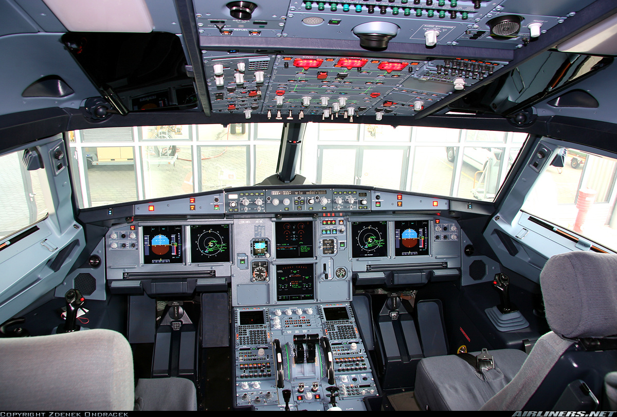
AIRBUS A 320 COCKPIT
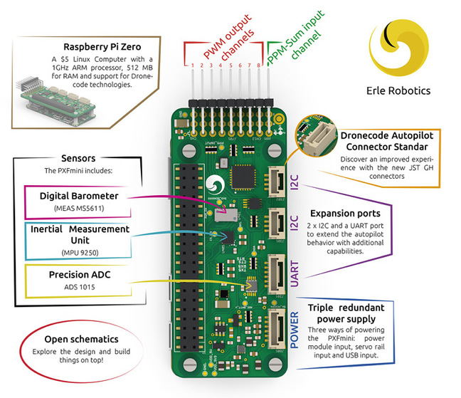
ELECTRONIC CIRCUIT AUTO PILOT

example concept of : Auto-pilot navigation and data transmission wiring diagram

Example of Auto Pilot Drone

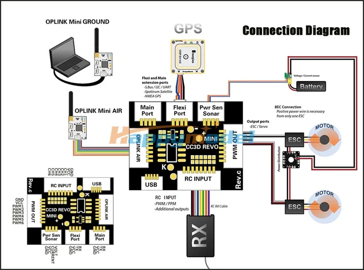
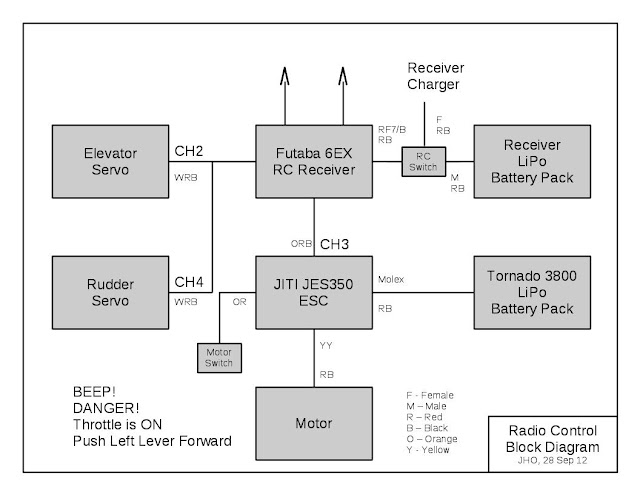
AUTO PILOT WIRING DIAGRAM
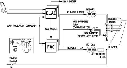
The Flight Augmentation Computer provides electronic control for the A320 rudder

Simplified RRV autopilot and instrumentation used for the ESS flight tests.

Airbus A320 thrust levers on the centre pedestal instrument panel. Switches and dials visible in
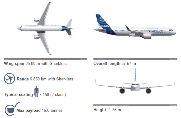
AIRBUS A 320 Data and Carrier
If you want to deepen the electronic system for aircraft systems and electronic control, please read the article I wrote on my Facebook, JESI ISE, hopefully blessed.
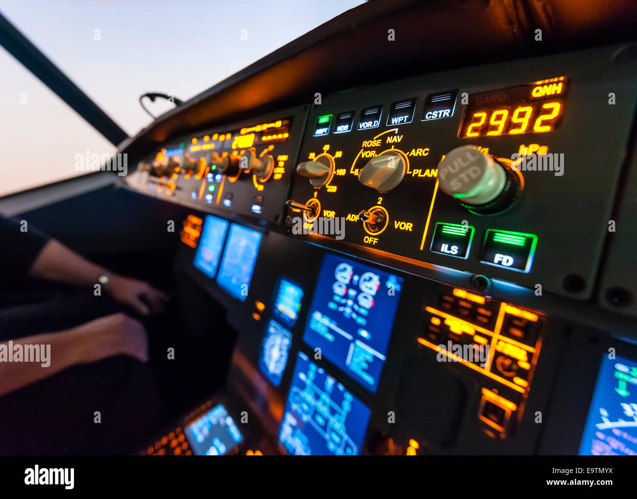
Cockpit of an Airbus A320 flight simulator that is used for training of professional airline pilots
+++++++++++++++++++++++++++++++++++++++++++++++++++++++++++++++++++++
+++++++++++++++++++++++++++++++++++++++++++++++++++++++++++++++++++++