Analogs of Basic Electronic Circuit Elements in a Free-Space Atom
CHIP
Using a thermal sample of laser-cooled rubidium atoms, we have constructed a neutral-atom circuit analogous to an electronic capacitor discharged through a resistor. The atoms are confined using what we call a free-space atom chip, an optical dipole trap created using a generalized phase-contrast imaging technique. We have also calculated theoretical values for the capacitance and resistance, which agree with our experiments, as well as theoretical value for an atomic analog of electrical inductance. We show that atomic capacitance is analogous to the quantum capacitance, the atomic resistance is analogous to the ballistic, or Sharvin resistance, and the atomic inductance is analogous to kinetic inductance.
Electronics is based on the manipulation of electrons, possibly enhanced by exploiting internal structure associated with spin (spintronics). Atomtronics seeks do the same with neutral atoms. The more complex internal structure of atoms makes the possibilities of such an architecture far richer than its electronic analog. Recently, persistent currents of superfluid neutral atoms have been created in ring circuits, which are close analogs to superconducting circuits1. There have also been efforts towards developing analogs to active electronic circuit elements such as diodes and transistors2. Any usable neutral atom circuit, however, will need analogs to the most basic electronic elements – resistors (R), capacitors (C) and inductors (L). Using a two-dimensional (2D) optical dipole potential3to generate what we call free-space atom chips, we have created and characterized a neutral-atom RLC circuit. We show that the resistance is analogous to ballistic (Sharvin4) resistance in metals, the inductance is analogous to kinetic inductance in superconductors5, and the capacitance is analogous to the quantum capacitance in nanoscale devices6,7.
A 2D neutral atom analog to an electronic RLC circuit can be realized with a classical ideal gas using two containers of areas A1 and A2 connected by a channel. In an electronic capacitor, a charge imbalance (Q) between two conductors produces a potential difference (ΔV). When a resistor connects the two conductors, electrons flow to eliminate the charge imbalance, causing ΔV to vanish. In our system, a number imbalance (N) between the two containers produces a chemical potential difference (Δμ). When a channel connects the two containers, atoms flow to eliminate the number imbalance, causing Δμ to vanish. To complete this analogy, we define a chemical capacitance,
with SI units of 1/J and with the same form as the electronic capacitance C = Q/ΔV.
The chemical potential of a 2D ideal gas is the change in free energy associated with changing the number of particles in the system8,
where k is Boltzmann's constant, h Planck's constant, T the temperature, n the 2D number density and m the mass of a particle in the gas. To determine the capacitance, we start by assuming the two chambers to be in equilibrium, with equal temperatures and equal densities, N1e/A1 = N2e/A2 = ne. Moving a small number of particles N fromA1 to A2 leads to an imbalance in the densities so that n1 = (N1e − N)/A1 and n2 = (N2e + N)/A2. Subtractingequation (2) with n1 from equation (2) with n2 leads to
This linear approximation is valid for N ≪ N1e and N2e. The experiment we describe below is within this limit. Combining equations (1) and (4) leads to an expression for the neutral-atom chemical capacitance,
where is the harmonic mean of A1 and A2, and εT is the thermal energy of the gas.
When a channel is opened between the chambers, it acts as a resistor and an inductor. To determine the values ofR and L, we examine the flow dynamics of the system. In a 2D ideal gas, the effusion rate F of atoms out of either container is given by
where Ai is the area of the container and w is the width of the channel. The total rate of change in atom number in container 1 can then be written as
where the second term on the right hand side of the equation, representing the rate that atoms enter container 1 due to leaving container 2, is evaluated at a time Δt earlier. This delay is due to the finite velocity of the atoms traversing the channel. We approximate this delay time using the average transverse velocity of an atom in the channel,
where l is the length of the channel. When we combine equations (5–8), and linearly expand the terms in equation (7) involving Δt, the result is analogous to Kirchhoff's law applied to a series RLC circuit,
with chemical resistance and inductance given by
with SI units of J · s and J · s2 respectively. Here,
is the average 2D momentum of the particles in one container. We dropped a second term in the resistance that is only significant when the channel represents a large portion of the entire area of the system. At this point the small N approximation breaks down, thus the second term is negligible when equation (9) is valid.
The chemical capacitance, resistance and inductance each have specific electronic analogs. Our capacitance results from the shift in chemical potential due to transfer of particles, the same effect that causes the quantum capacitance in nanostructures6,7. For 2D quantum dots with areas A1 and A2, the quantum capacitance is given by
where εF is the Fermi energy of the gas. This is similar to equation (5), with an electrical factor of e2 and the thermal energy replaced by the 2D Fermi energy. It is interesting to note that taking in equation (12) does not yield the correct classical limit of the quantum capacitance, which is equation (5).
In electronics, a point junction smaller than the mean free path of the electrons creates what is known as the Sharvin resistance. This arises purely from the ballistic motion of the electrons because there is no scattering of electrons in the point junction itself. For a 2D electronic system the Sharvin resistance is given by9
where is the Fermi momentum. This has the same form as our chemical resistance in equation (10), differing by a factor of e2 and a numerical factor because the Sharvin resistance is derived for a 2D, charged, T = 0 Fermi gas, which has a different velocity distribution than our neutral, classical gas.
There is an inductance in electronic systems, the kinetic inductance5, that arises due to the kinetic energy associated with current flow in a wire,
Again, this shares the same form as our chemical inductance, differing by a factor of e2 and a numerical factor.
The methods that we used to calculate the capacitance and resistance of classical ideal gas circuit elements can be extended to other atomic systems such as degenerate Fermi gases and Bose-Einstein condensates. To define the chemical capacitance, all that is needed is the dependence of the chemical potential on atom number. The momentum distribution of the sample determines the effusion rate, which leads directly to the chemical resistance. Table 1 summarizes these results for 2D and 3D non-interacting classical gases, non-interacting degenerate Fermi gases, and BECs. The BEC cases are derived using the Gross-Pitaevskii (GP) equations for hard-wall containers in the Thomas-Fermi limit. In this case it is not sufficient to describe the system as consisting of point particles with classical trajectories, which is needed to derive the resistance, thus this is omitted. The 2D Fermi gas capacitance formula is exact. The classical gas and the 3D Fermi gas capacitances are all the first-order terms in Taylor series expansions.
Table 1
Summary of chemical capacitances and resistances for various systems. In the 2D systems, is the harmonic mean of the two container areas, w is the cross-sectional width of the channel, the average classical 2D momentum is , and the 2D Fermi momentum is . In the 3D systems, is the harmonic mean of the two container volumes, a is the cross-sectional area of the channel, the average classical 3D momentum is , and the 3D Fermi momentum is
Cc
Rc
2D
3D
2D
3D
Classical
Fermi T = 0
BEC (GP)
Results
To realize a classical ideal gas neutral atom capacitor, we begin with a sample of 87Rb atoms, cooled and confined using a magneto-optical trap10 (MOT). This MOT is created inside of a free-space atom chip that consists of two circular containers separated by a rectangular channel. The method used for creating this potential is discussed in the methods section. At time t = 0, the atoms are released from the MOT after a final cooling stage, and allowed to flow between the containers for a variable amount of time, after which a fluorescence image is taken of the atoms. We directly image the gas flow between the containers with this setup. The evolution of this system can be seen in figure 1. We point out that the arrangement employed is similar to that used in atom-optics billiards where a circular potential is known to lead to ”regular” dynamics, which would affect the effusion rate in our experiment11. In our case however, the container walls are not smooth, as discussed in the methods. Because of this the atom-wall collisions are not always specular, leading to ergodic dynamics, thus our use of equation (6) is valid. Figure 2shows the decay of the normalized number imbalance N/Ne as a function of time for several channel widths, as well as the solution to the RLC differential equation for the parameters used. The only fit parameter for the RLC solution is the initial atom number imbalance.
Images of a discharging atom capacitor with a channel width of 340 μm. The atoms are loaded into the right container and released from the MOT at t = 0 ms. The images are snapshots at 5 ms intervals, starting at t = 5 ms (viewed left to right, top to bottom). Each frame is the average of eight individual experimental runs, and is scaled independently of the other frames.
Comparison of experimental data to analytic solution.
The points indicate the experimental data and the solid lines represent the relevant RLC solution. The black line is for a channel width of 240 μm, the red 384 μm, and the green 576 μm. From equations (5,10), the RC time constant, , can be calculated for each of these systems to be 34, 21 and 14 ms respectively. The diameter of each container is 600 μm. For each experimental data point, 8 individual runs were averaged. The error bars are the standard deviation of the mean.
Discussion
For channels up to approximately half the width of the containers, the data and theory agree well. For channels that approach the width of the containers (green plot in figure 2), the assumption of local equilibrium is no longer valid, and good agreement is not expected, and indeed is not seen. The nature of the disagreement appears to be inductive, showing a significant overshoot. This however, is not the inductance we derive, which is too small to account for this phenomenon.
We have experimentally demonstrated atomtronic capacitors and resistors, and shown how to construct an atomtronic inductor, all on a free-space atom chip defined using 2D optical dipole potentials. These basic linear devices are necessary for biasing active devices, and are also essential for constructing oscillators and filters. Integration into systems such as loops containing BECs1, atomtronic Josephson junctions based on BECs, BEC analogs of SQUIDs12, and atomtronic batteries, diodes and transistors2, is made much more simple through the flexibility of our atom-chip technique.
Methods
To create the trap geometry that was necessary to carry out this experiment, we used what we call free-space atom chips, which are a type of crossed optical dipole trap. We use a sheet dipole trap to confine the atoms to a 2D plane. On top of this, we project an arbitrary 2D optical dipole potential to create the geometry necessary for the experiment. In this particular experiment, the sheet trap was a blue-detuned, repulsive beam confining the atoms from below, with gravity confining them from above.
In the plane, we create our arbitrary 2D pattern using a generalized phase contrast approach13. This scheme is shown in figure 3 a). A phase pattern is imprinted onto an input TEM00 beam and sent through a 4-f imaging system. We used a 2D spatial light modulator (SLM) to imprint the pattern. At the Fourier plane, there is a phase-contrast filter that shifts the phase of the lowest spatial frequencies, which exist near the optical axis, by π relative to the remaining spatial frequencies of the beam. The two parts of the beam interfere in the output plane to produce an intensity profile that mirrors the input phase mask. This plane is imaged onto the sheet potential, effectively etching the sheet to create our free-space atom chip. The intensity profile for one of our capacitor potentials is shown in figure 3 b). This method, with the use of the computer-addressable SLM, allows us to create and easily modify the confining potential used in the experiment. This ability was integral to this experiment as it allowed us to easily adjust the channel width. Because of the pixelazation of our SLM, the walls of our containers are rough on the order of 10 μm.
Phase-Contrast imaging system with typical output.
a) A basic phase-contrast imaging system with input phase mask, phase-contrast filter, and 4-f lens arrangement, and b) a typical output pattern used to create blue-detuned optical dipole potentials for an atom capacitor. The blue (white) areas correspond to light (absence of light).
In the experiment, the atoms start with a temperature of approximately 40 μK. The potential height of the container walls is approximately 60 μK. Since there is a significant population of atoms in the thermal distribution with an energy that can escape the trap, there is a truncated velocity distribution in the sample. The number density of the atoms in this experiment is not high enough for rethermalization to occur. Time-of-flight expansion experiments have shown that the truncated distribution is well approximated by a thermal distribution at a temperature of about 20 μK, which is the temperature used in the analytical RLC plots in figure 3. The potential height of the sheet below the atoms is approximately 500 μK, which is effectively infinite when compared to our atom temperatures.
The images were taken by switching on the original near-resonant MOT light for 100 μs, and collecting the light scattered by the atoms using a single lens, one-to-one imaging system with the image plane on the sensor of our camera. A background image was then subtracted to obtain the final image for any one shot. Eight individual runs were then averaged together for each frame of figure 1. To count the atom number difference plotted in figure 2, each imaged was masked off to count the number of atoms in either the left or right container. The error bars in this plot are the standard deviation in the mean for this measurement for the eight runs. Each image was taken after a short (2 ms) time-of-flight for technical reasons.
XO___XO What is Selenium?
the chemical element of atomic number 34, a gray crystalline nonmetal with semiconducting properties.
Early Components — Rectifiers
Converting ac to dc has been accomplished by several different types of
rectifiers through the years. Here are a few of the more common types of
rectifiers used in the past 100 years.
Mercury arc rectifiers
Mercury arc rectifiers,
also known as "Cooper Hewitt Rectifiers" were used in the early 20th
century before the use of semiconductors to convert alternating current
to direct current in high-voltage and -current applications. Constructed
of glass for low-power applications and steel tanks for higher-power
applications, Mercury Arc rectifiers work on the principle that an arc
of electricity between an anode and a pool of mercury will only pass
current in one direction. It was not uncommon to have a glass mercury
arc rectifier with several anodes for higher-power applications that
resembled a large glass octopus.
Today these large odd-shaped
tubes are sought after by vacuum tube collectors. Unfortunately since
they contain mercury, they are considered hazardous material and should
not be shipped by common carrier or the U.S. Mail. The large amount of
liquid mercury in these rectifiers has lead to many of them being
recycled, further reducing the number that turn up for collectors. Today
expect to pay $50 to $150 for a two anode rectifier and several hundred
dollars for mercury arc rectifiers with more than two anodes. It's not
very likely, but if you are looking to add one to a collection, you
might find one in your local area, so proper packing and shipping won't
be a concern and additional cost.
The Raytheon BH vacuum tube rectifier
In
the second half of the 1920s, Raytheon developed the BH rectifier tube.
Its primary purpose was to supply enough power to convert the new
household 110-V ac current from a lighting circuit into the two or three
different voltages needed to replace the costly batteries in most early
battery powered home radios. Containing two cathodes in fireproof
sleeves, the BH tube was able to supply enough power in a package the
size of a standard radio tube without frequent burn out. The BH
rectifier tube also had a consistent voltage drop, which meant the
associated power supply circuits needed less filtering and voltage
regulation.
A Raytheon BH Tube Rectifier.
The
BH tube was used extensively in radio battery eliminators through the
second half of the 1920s. A BH tube is easily recognized by its
mushroom-shaped anode inside the top of the tube.
Typical construction of a BH tube rectifier.
Since
the BH tube was primarily used in battery eliminators and not the radio
itself, the BH tube is harder to find. The current demand for the BH
tube is primarily for use in restoring a 1920s battery eliminator or as a
display item in a vacuum tube collection. Even though these are less
common, they usually sell for $10 to $25 in good working condition.
Tungar bulbs
Tungar
bulbs were half-wave rectifiers and commonly used in battery chargers,
carbon-arc lamps, early high-power speaker systems, and other industrial
applications. The "Tungar" name is derived from the tungsten filament
and argon gas used in these early rectifiers. The term "bulb" most
likely comes from the large-diameter screw-type base many had.
The Tungar bulb rectifier
Tungar
bulbs were still used up to the 1970s in stage lighting. Today they are
easy to find, so their value is not great. Typical prices range from
$25 to $40 for nice collector examples with their original porcelain
sockets, but Tungar bulbs in working condition may sometimes be found
for as little as $15 to $20.
The Number 80 vacuum tube
The
80 vacuum tube is a full-wave rectifier. This type of four-pin glass
rectifier tube appeared around 1926. Like the BH tube, the 80's early
development was driven by the implementation of electricity in the home
and increasing demand for home radios that could run off the new ac
electric light wiring. A common #80 vacuum tube.
The 80 was most commonly used in home radios and tube amplifiers in the 1930s. Different manufactures numbered their 80 as 280, UX280
and other numbers. This was the most common type of rectifier vacuum
tube and was used in millions of radios up to the 1940s, when it was
replaced by updated versions based on the same design. Today an unused
(new-old stock) or tested number 80 vacuum tube sells for between $12
and $25.
Selenium rectifiers
One of
the more interesting rectifiers was used after World War II. Developed
in the 1930s, the selenium rectifier contained a stack of several steel
or aluminum plates coated with bismuth or nickel, with a thicker layer
of selenium and a halogen element added. Each plate could typically
withstand 20 to 22 reverse volts and the voltage rating was easily
increased by adding additional plates to the stack at the time of
production. Selenium rectifiers were more efficient than vacuum tubes
but unfortunately, they had a shorter usable lifespan and could not be
easily replaced by the end user. By the 1970s they were replaced by the
smaller, more efficient and reliable silicon diode, which was much
cheaper to manufacture.
Selenium Rectifiers voltage rating was increased by adding plates.
Selenium
rectifiers today have little or no value to a collector or equipment
restorer. I have seen selenium rectifiers rebuilt by inserting a diode
inside to maintain the original look but most restorers and service
technicians today simply replace them with a modern rectifier.
Atomtronics
Atomtronics is an emerging sub-field of ultracold atomic physics which encompasses a broad range of topics featuring guided atomic matter waves. The systems typically include components analogous to those found in electronic or optical systems, such as beam splitters and transistors. Applications range from studies of fundamental physics to the development of practical devices.
Etymology
Atomtronics is a contraction of "atom" and "electronics", in reference to the creation of atomic analogues of electronic components, such as transistors and diodes, and also electronic materials such as semiconductors.[1] The field itself has considerable overlap with atom optics and quantum simulation, and is not strictly limited to the development of electronic-like components.
Methodology
Three major elements are required for an atomtronic circuit. The first is a Bose-Einstein condensate, which is needed for its coherent and superfluid properties, although an ultracold Fermi gas may also be used for certain applications. The second is a tailored trapping potential, which can be generated optically, magnetically,
or using a combination of both. The final element is a method to induce
movement of atoms within the potential, which can be achieved in a
number of ways. For example, a transistor-like atomtronic circuit may be
realized by a ring-shaped trap divided into two by two moveable weak
barriers, with the two separate parts of the ring acting as the drain
and the source, and the barriers acting as the gate. As the barriers
move, atoms flow from the source to the drain.
Applications
The field of atomtronics is still very young. Any schemes realized thus far are proof-of-principle. Applications include:
Obstacles to the development of practical sensing devices are largely
due to the technical challenges of creating Bose-Einstein condensates,
as they require bulky lab-based setups not easily suitable for
transportation, although creating portable experimental setups is an
active area of research.
Robotics
Robotics is an interdisciplinary branch of engineering and science that includes mechanical engineering, electronics engineering, computer science, and others. Robotics deals with the design, construction, operation, and use of robots, as well as computer systems for their control, sensory feedback, and information processing.
These technologies are used to develop machines that can
substitute for humans and replicate human actions. Robots can be used in
any situation and for any purpose, but today many are used in dangerous
environments (including bomb detection and deactivation),
manufacturing processes, or where humans cannot survive. Robots can
take on any form but some are made to resemble humans in appearance.
This is said to help in the acceptance of a robot in certain replicative
behaviors usually performed by people. Such robots attempt to replicate
walking, lifting, speech, cognition, and basically anything a human can
do. Many of today's robots are inspired by nature, contributing to the
field of bio-inspired robotics.
The concept of creating machines that can operate autonomously dates back to classical times, but research into the functionality and potential uses of robots did not grow substantially until the 20th century.[1]
Throughout history, it has been frequently assumed that robots will one
day be able to mimic human behavior and manage tasks in a human-like
fashion. Today, robotics is a rapidly growing field, as technological
advances continue; researching, designing, and building new robots serve
various practical purposes, whether domestically, commercially, or militarily.
Many robots are built to do jobs that are hazardous to people such as
defusing bombs, finding survivors in unstable ruins, and exploring mines
and shipwrecks. Robotics is also used in STEM (science, technology, engineering, and mathematics) as a teaching aid.
Robotics is a branch of engineering that involves the conception,
design, manufacture, and operation of robots. This field overlaps with
electronics, computer science, artificial intelligence, mechatronics,
nanotechnology and bioengineering
Robotic aspects
Mechanical construction
Electrical aspect
A level of programming
There are many types of robots; they are used in many different
environments and for many different uses, although being very diverse in
application and form they all share three basic similarities when it
comes to their construction:
Robots all have some kind of mechanical construction, a frame,
form or shape designed to achieve a particular task. For example, a
robot designed to travel across heavy dirt or mud, might use caterpillar tracks.
The mechanical aspect is mostly the creator's solution to completing
the assigned task and dealing with the physics of the environment around
it. Form follows function.
Robots have electrical components which power and control the machinery. For example, the robot with caterpillar tracks
would need some kind of power to move the tracker treads. That power
comes in the form of electricity, which will have to travel through a
wire and originate from a battery, a basic electrical circuit. Even petrol powered machines
that get their power mainly from petrol still require an electric
current to start the combustion process which is why most petrol powered
machines like cars, have batteries. The electrical aspect of robots is
used for movement (through motors), sensing (where electrical signals
are used to measure things like heat, sound, position, and energy
status) and operation (robots need some level of electrical energy supplied to their motors and sensors in order to activate and perform basic operations)
All robots contain some level of computer programming
code. A program is how a robot decides when or how to do something. In
the caterpillar track example, a robot that needs to move across a muddy
road may have the correct mechanical construction and receive the
correct amount of power from its battery, but would not go anywhere
without a program telling it to move. Programs are the core essence of a
robot, it could have excellent mechanical and electrical construction,
but if its program is poorly constructed its performance will be very
poor (or it may not perform at all). There are three different types of
robotic programs: remote control, artificial intelligence and hybrid. A
robot with remote control
programing has a preexisting set of commands that it will only perform
if and when it receives a signal from a control source, typically a
human being with a remote control. It is perhaps more appropriate to
view devices controlled primarily by human commands as falling in the
discipline of automation rather than robotics. Robots that use artificial intelligence
interact with their environment on their own without a control source,
and can determine reactions to objects and problems they encounter using
their preexisting programming. Hybrid is a form of programming that
incorporates both AI and RC functions.
Applications
As
more and more robots are designed for specific tasks this method of
classification becomes more relevant. For example, many robots are
designed for assembly work, which may not be readily adaptable for other
applications. They are termed as "assembly robots". For seam welding,
some suppliers provide complete welding systems with the robot i.e. the
welding equipment along with other material handling facilities like
turntables etc. as an integrated unit. Such an integrated robotic system
is called a "welding robot" even though its discrete manipulator unit
could be adapted to a variety of tasks. Some robots are specifically
designed for heavy load manipulation, and are labelled as "heavy duty
robots".
Current and potential applications include:
Caterpillar plans to develop remote controlled machines and expects to develop fully autonomous heavy robots by 2021.[19] Some cranes already are remote controlled.
It was demonstrated that a robot can perform a herding[20] task.
Robots are increasingly used in manufacturing (since the 1960s). In
the auto industry, they can amount for more than half of the "labor".
There are even "lights off" factories such as an IBM keyboard manufacturing factory in Texas that is 100% automated.[21]
Robots such as HOSPI[22] are used as couriers in hospitals (hospital robot). Other hospital tasks performed by robots are receptionists, guides and porters helpers.[23]
Robot combat
for sport – hobby or sport event where two or more robots fight in an
arena to disable each other. This has developed from a hobby in the
1990s to several TV series worldwide.
Cleanup of contaminated areas, such as toxic waste or nuclear facilities.[29]
At present, mostly (lead–acid) batteries
are used as a power source. Many different types of batteries can be
used as a power source for robots. They range from lead–acid batteries,
which are safe and have relatively long shelf lives but are rather heavy
compared to silver–cadmium batteries that are much smaller in volume
and are currently much more expensive. Designing a battery-powered robot
needs to take into account factors such as safety, cycle lifetime and weight. Generators, often some type of internal combustion engine,
can also be used. However, such designs are often mechanically complex
and need a fuel, require heat dissipation and are relatively heavy. A
tether connecting the robot to a power supply would remove the power
supply from the robot entirely. This has the advantage of saving weight
and space by moving all power generation and storage components
elsewhere. However, this design does come with the drawback of
constantly having a cable connected to the robot, which can be difficult
to manage.[32] Potential power sources could be:
Actuators are the "muscles" of a robot, the parts which convert stored energy
into movement. By far the most popular actuators are electric motors
that rotate a wheel or gear, and linear actuators that control
industrial robots in factories. There are some recent advances in
alternative types of actuators, powered by electricity, chemicals, or
compressed air.
Electric motors
The vast majority of robots use electric motors, often brushed and
brushless DC motors in portable robots or AC motors in industrial robots
and CNC
machines. These motors are often preferred in systems with lighter
loads, and where the predominant form of motion is rotational.
Linear actuators
Various types of linear actuators move in and out instead of by
spinning, and often have quicker direction changes, particularly when
very large forces are needed such as with industrial robotics. They are
typically powered by compressed and oxidized air (pneumatic actuator) or an oil (hydraulic actuator).
Series elastic actuators
A
flexure is designed as part of the motor actuator, to improve safety
and provide robust force control, energy efficiency, shock absorption
(mechanical filtering) while reducing excessive wear on the transmission
and other mechanical components. The resultant lower reflected inertia
can improve safety when a robot is interacting with humans or during
collisions. It has been used in various robots, particularly advanced
manufacturing robots and[33] walking humanoid robots.[34]
Air muscles
Pneumatic artificial muscles, also known as air muscles, are special
tubes that expand(typically up to 40%) when air is forced inside them.
They are used in some robot applications.
Muscle wire
Muscle wire, also known as shape memory alloy, Nitinol® or Flexinol®
wire, is a material which contracts (under 5%) when electricity is
applied. They have been used for some small robot applications.
Electroactive polymers
EAPs or EPAMs are a new
plastic material that can contract substantially (up to 380% activation
strain) from electricity, and have been used in facial muscles and arms
of humanoid robots,[40] and to enable new robots to float,[41] fly, swim or walk.[42]
Piezo motors
Recent alternatives to DC motors are piezo motors or ultrasonic motors. These work on a fundamentally different principle, whereby tiny piezoceramic
elements, vibrating many thousands of times per second, cause linear or
rotary motion. There are different mechanisms of operation; one type
uses the vibration of the piezo elements to step the motor in a circle
or a straight line.[43] Another type uses the piezo elements to cause a nut to vibrate or to drive a screw. The advantages of these motors are nanometer resolution, speed, and available force for their size.[44] These motors are already available commercially, and being used on some robots.[45][46]
Elastic nanotubes
Elastic nanotubes are a promising artificial muscle technology in
early-stage experimental development. The absence of defects in carbon nanotubes enables these filaments to deform elastically by several percent, with energy storage levels of perhaps 10 J/cm3
for metal nanotubes. Human biceps could be replaced with an 8 mm
diameter wire of this material. Such compact "muscle" might allow future
robots to outrun and outjump humans.[47]
Sensing
Sensors allow robots to receive information about a certain
measurement of the environment, or internal components. This is
essential for robots to perform their tasks, and act upon any changes in
the environment to calculate the appropriate response. They are used
for various forms of measurements, to give the robots warnings about
safety or malfunctions, and to provide real-time information of the task
it is performing.
Current robotic and prosthetic hands receive far less tactile
information than the human hand. Recent research has developed a
tactile sensor array that mimics the mechanical properties and touch
receptors of human fingertips.[48][49]
The sensor array is constructed as a rigid core surrounded by
conductive fluid contained by an elastomeric skin. Electrodes are
mounted on the surface of the rigid core and are connected to an
impedance-measuring device within the core. When the artificial skin
touches an object the fluid path around the electrodes is deformed,
producing impedance changes that map the forces received from the
object. The researchers expect that an important function of such
artificial fingertips will be adjusting robotic grip on held objects.
Scientists from several European countries and Israel developed a prosthetic hand in 2009, called SmartHand, which functions like a real one—allowing patients to write with it, type on a keyboard,
play piano and perform other fine movements. The prosthesis has sensors
which enable the patient to sense real feeling in its fingertips.[50]
Vision
Computer vision
is the science and technology of machines that see. As a scientific
discipline, computer vision is concerned with the theory behind
artificial systems that extract information from images. The image data
can take many forms, such as video sequences and views from cameras.
In most practical computer vision applications, the computers are
pre-programmed to solve a particular task, but methods based on
learning are now becoming increasingly common.
Computer vision systems rely on image sensors which detect electromagnetic radiation which is typically in the form of either visible light or infra-red light. The sensors are designed using solid-state physics. The process by which light propagates and reflects off surfaces is explained using optics. Sophisticated image sensors even require quantum mechanics
to provide a complete understanding of the image formation process.
Robots can also be equipped with multiple vision sensors to be better
able to compute the sense of depth in the environment. Like human eyes,
robots' "eyes" must also be able to focus on a particular area of
interest, and also adjust to variations in light intensities.
There is a subfield within computer vision where artificial systems are designed to mimic the processing and behavior of biological system,
at different levels of complexity. Also, some of the learning-based
methods developed within computer vision have their background in
biology.
Other
Other common forms of sensing in robotics use lidar, radar, and sonar.
Baxter, a modern and versatile industrial robot developed by Rodney Brooks
Robots need to manipulate objects; pick up, modify, destroy, or
otherwise have an effect. Thus the "hands" of a robot are often referred
to as end effectors,[51] while the "arm" is referred to as a manipulator.[52]
Most robot arms have replaceable effectors, each allowing them to
perform some small range of tasks. Some have a fixed manipulator which
cannot be replaced, while a few have one very general purpose
manipulator, for example, a humanoid hand.[53]
Learning how to manipulate a robot often requires a close feedback
between human to the robot, although there are several methods for
remote manipulation of robots.[54]
Mechanical grippers
One
of the most common effectors is the gripper. In its simplest
manifestation, it consists of just two fingers which can open and close
to pick up and let go of a range of small objects. Fingers can for
example, be made of a chain with a metal wire run through it.[55] Hands that resemble and work more like a human hand include the Shadow Hand and the Robonaut hand.[56] Hands that are of a mid-level complexity include the Delft hand.[57][58]
Mechanical grippers can come in various types, including friction and
encompassing jaws. Friction jaws use all the force of the gripper to
hold the object in place using friction. Encompassing jaws cradle the
object in place, using less friction.
Vacuum grippers
Vacuum grippers are very simple astrictive[59] devices that can hold very large loads provided the prehension surface is smooth enough to ensure suction.
Pick and place robots for electronic components and for large
objects like car windscreens, often use very simple vacuum grippers.
General purpose effectors
Some advanced robots are beginning to use fully humanoid hands, like the Shadow Hand, MANUS,[60] and the Schunk hand.[61] These are highly dexterous manipulators, with as many as 20 degrees of freedom and hundreds of tactile sensors.[62]
For simplicity, most mobile robots have four wheels or a number of continuous tracks.
Some researchers have tried to create more complex wheeled robots with
only one or two wheels. These can have certain advantages such as
greater efficiency and reduced parts, as well as allowing a robot to
navigate in confined places that a four-wheeled robot would not be able
to.
Two-wheeled balancing robots
Balancing robots generally use a gyroscope
to detect how much a robot is falling and then drive the wheels
proportionally in the same direction, to counterbalance the fall at
hundreds of times per second, based on the dynamics of an inverted pendulum.[63] Many different balancing robots have been designed.[64] While the Segway
is not commonly thought of as a robot, it can be thought of as a
component of a robot, when used as such Segway refer to them as RMP
(Robotic Mobility Platform). An example of this use has been as NASA's Robonaut that has been mounted on a Segway.[65]
One-wheeled balancing robots
A one-wheeled balancing robot is an extension of a two-wheeled
balancing robot so that it can move in any 2D direction using a round
ball as its only wheel. Several one-wheeled balancing robots have been
designed recently, such as Carnegie Mellon University's "Ballbot" that is the approximate height and width of a person, and Tohoku Gakuin University's "BallIP".[66]
Because of the long, thin shape and ability to maneuver in tight
spaces, they have the potential to function better than other robots in
environments with people.[67]
Several attempts have been made in robots that are completely inside a
spherical ball, either by spinning a weight inside the ball,[68][69] or by rotating the outer shells of the sphere.[70][71] These have also been referred to as an orb bot[72] or a ball bot.[73][74]
Six-wheeled robots
Using six wheels instead of four wheels can give better traction or grip in outdoor terrain such as on rocky dirt or grass.
Tank tracks provide even more traction than a six-wheeled robot.
Tracked wheels behave as if they were made of hundreds of wheels,
therefore are very common for outdoor and military robots, where the
robot must drive on very rough terrain. However, they are difficult to
use indoors such as on carpets and smooth floors. Examples include
NASA's Urban Robot "Urbie".[75]
Walking applied to robots
Walking
is a difficult and dynamic problem to solve. Several robots have been
made which can walk reliably on two legs, however, none have yet been
made which are as robust as a human. There has been much study on human
inspired walking, such as AMBER lab which was established in 2008 by the
Mechanical Engineering Department at Texas A&M University.[76] Many other robots have been built that walk on more than two legs, due to these robots being significantly easier to construct.[77][78]
Walking robots can be used for uneven terrains, which would provide
better mobility and energy efficiency than other locomotion methods.
Hybrids too have been proposed in movies such as I, Robot,
where they walk on two legs and switch to four (arms+legs) when going
to a sprint. Typically, robots on two legs can walk well on flat floors
and can occasionally walk up stairs. None can walk over rocky, uneven terrain. Some of the methods which have been tried are:
ZMP technique
The zero moment point (ZMP) is the algorithm used by robots such as Honda's ASIMO. The robot's onboard computer tries to keep the total inertial forces (the combination of Earth's gravity and the acceleration and deceleration of walking), exactly opposed by the floor reaction force (the force of the floor pushing back on the robot's foot). In this way, the two forces cancel out, leaving no moment (force causing the robot to rotate and fall over).[79]
However, this is not exactly how a human walks, and the difference is
obvious to human observers, some of whom have pointed out that ASIMO
walks as if it needs the lavatory.[80][81][82]
ASIMO's walking algorithm is not static, and some dynamic balancing is
used (see below). However, it still requires a smooth surface to walk
on.
Hopping
Several robots, built in the 1980s by Marc Raibert at the MIT
Leg Laboratory, successfully demonstrated very dynamic walking.
Initially, a robot with only one leg, and a very small foot could stay
upright simply by hopping. The movement is the same as that of a person on a pogo stick. As the robot falls to one side, it would jump slightly in that direction, in order to catch itself.[83] Soon, the algorithm was generalised to two and four legs. A bipedal robot was demonstrated running and even performing somersaults.[84] A quadruped was also demonstrated which could trot, run, pace, and bound.[85] For a full list of these robots, see the MIT Leg Lab Robots page.[86]
Dynamic balancing (controlled falling)
A
more advanced way for a robot to walk is by using a dynamic balancing
algorithm, which is potentially more robust than the Zero Moment Point
technique, as it constantly monitors the robot's motion, and places the
feet in order to maintain stability.[87] This technique was recently demonstrated by Anybots' Dexter Robot,[88] which is so stable, it can even jump.[89] Another example is the TU Delft Flame.
Passive dynamics
Perhaps the most promising approach utilizes passive dynamics where the momentum of swinging limbs is used for greater efficiency. It has been shown that totally unpowered humanoid mechanisms can walk down a gentle slope, using only gravity
to propel themselves. Using this technique, a robot need only supply a
small amount of motor power to walk along a flat surface or a little
more to walk up a hill. This technique promises to make walking robots at least ten times more efficient than ZMP walkers, like ASIMO.[90][91]
Other methods of locomotion
Flying
Two robot snakes. Left one has 64 motors (with 2 degrees of freedom per segment), the right one 10.
A modern passenger airliner is essentially a flying robot, with two humans to manage it. The autopilot can control the plane for each stage of the journey, including takeoff, normal flight, and even landing.[92] Other flying robots are uninhabited and are known as unmanned aerial vehicles
(UAVs). They can be smaller and lighter without a human pilot on board,
and fly into dangerous territory for military surveillance missions.
Some can even fire on targets under command. UAVs are also being
developed which can fire on targets automatically, without the need for a
command from a human. Other flying robots include cruise missiles, the Entomopter, and the Epson micro helicopter robot.
Robots such as the Air Penguin, Air Ray, and Air Jelly have
lighter-than-air bodies, propelled by paddles, and guided by sonar.
Snaking
Several snake
robots have been successfully developed. Mimicking the way real snakes
move, these robots can navigate very confined spaces, meaning they may
one day be used to search for people trapped in collapsed buildings.[93] The Japanese ACM-R5 snake robot[94] can even navigate both on land and in water.[95]
Skating
A small number of skating
robots have been developed, one of which is a multi-mode walking and
skating device. It has four legs, with unpowered wheels, which can
either step or roll.[96] Another robot, Plen, can use a miniature skateboard or roller-skates, and skate across a desktop.[97]
Capuchin, a climbing robot
Climbing
Several
different approaches have been used to develop robots that have the
ability to climb vertical surfaces. One approach mimics the movements of
a human climber on a wall with protrusions; adjusting the center of mass and moving each limb in turn to gain leverage. An example of this is Capuchin,[98]
built by Dr. Ruixiang Zhang at Stanford University, California. Another
approach uses the specialized toe pad method of wall-climbing geckoes, which can run on smooth surfaces such as vertical glass. Examples of this approach include Wallbot[99] and Stickybot.[100] China's Technology Daily reported on November 15, 2008, that Dr. Li Hiu Yeung and his research group of New Concept Aircraft (Zhuhai) Co., Ltd. had successfully developed a bionic gecko robot named "Speedy Freelander".
According to Dr. Li, the gecko robot could rapidly climb up and down a
variety of building walls, navigate through ground and wall fissures,
and walk upside-down on the ceiling. It was also able to adapt to the
surfaces of smooth glass, rough, sticky or dusty walls as well as
various types of metallic materials. It could also identify and
circumvent obstacles automatically. Its flexibility and speed were
comparable to a natural gecko. A third approach is to mimic the motion
of a snake climbing a pole.[citation needed].
Swimming (Piscine)
It is calculated that when swimming some fish can achieve a propulsive efficiency greater than 90%.[101] Furthermore, they can accelerate and maneuver far better than any man-made boat or submarine,
and produce less noise and water disturbance. Therefore, many
researchers studying underwater robots would like to copy this type of
locomotion.[102] Notable examples are the Essex University Computer Science Robotic Fish G9,[103] and the Robot Tuna built by the Institute of Field Robotics, to analyze and mathematically model thunniform motion.[104] The Aqua Penguin,[105] designed and built by Festo of Germany, copies the streamlined shape and propulsion by front "flippers" of penguins. Festo have also built the Aqua Ray and Aqua Jelly, which emulate the locomotion of manta ray, and jellyfish, respectively.
Robotic Fish: iSplash-II
In 2014 iSplash-II was developed by PhD student Richard James
Clapham and Prof. Huosheng Hu at Essex University. It was the first
robotic fish capable of outperforming real carangiform fish in terms of
average maximum velocity (measured in body lengths/ second) and
endurance, the duration that top speed is maintained.[106] This build attained swimming speeds of 11.6BL/s (i.e. 3.7 m/s).[107] The first build, iSplash-I (2014) was the first robotic platform to apply a full-body length carangiform
swimming motion which was found to increase swimming speed by 27% over
the traditional approach of a posterior confined waveform.[108]
Sailboat robots have also been developed in order to make measurements at the surface of the ocean. A typical sailboat robot is Vaimos[109]
built by IFREMER and ENSTA-Bretagne. Since the propulsion of sailboat
robots uses the wind, the energy of the batteries is only used for the
computer, for the communication and for the actuators (to tune the
rudder and the sail). If the robot is equipped with solar panels, the
robot could theoretically navigate forever. The two main competitions of
sailboat robots are WRSC, which takes place every year in Europe, and Sailbot.
Though a significant percentage of robots in commission today are
either human controlled or operate in a static environment, there is an
increasing interest in robots that can operate autonomously in a dynamic
environment. These robots require some combination of navigation hardware and software
in order to traverse their environment. In particular, unforeseen
events (e.g. people and other obstacles that are not stationary) can
cause problems or collisions. Some highly advanced robots such as ASIMO and Meinü robot have particularly good robot navigation hardware and software. Also, self-controlled cars, Ernst Dickmanns' driverless car, and the entries in the DARPA Grand Challenge,
are capable of sensing the environment well and subsequently making
navigational decisions based on this information. Most of these robots
employ a GPS navigation device with waypoints, along with radar, sometimes combined with other sensory data such as lidar, video cameras, and inertial guidance systems for better navigation between waypoints.
The state of the art in sensory intelligence for robots will have to
progress through several orders of magnitude if we want the robots
working in our homes to go beyond vacuum-cleaning the floors. If robots
are to work effectively in homes and other non-industrial environments,
the way they are instructed to perform their jobs, and especially how
they will be told to stop will be of critical importance. The people who
interact with them may have little or no training in robotics, and so
any interface will need to be extremely intuitive. Science fiction
authors also typically assume that robots will eventually be capable of
communicating with humans through speech, gestures, and facial expressions, rather than a command-line interface.
Although speech would be the most natural way for the human to
communicate, it is unnatural for the robot. It will probably be a long
time before robots interact as naturally as the fictional C-3PO, or Data of Star Trek, Next Generation.
Speech recognition
Interpreting the continuous flow of sounds coming from a human, in real time, is a difficult task for a computer, mostly because of the great variability of speech.[110] The same word, spoken by the same person may sound different depending on local acoustics, volume, the previous word, whether or not the speaker has a cold, etc.. It becomes even harder when the speaker has a different accent.[111]
Nevertheless, great strides have been made in the field since Davis,
Biddulph, and Balashek designed the first "voice input system" which
recognized "ten digits spoken by a single user with 100% accuracy" in
1952.[112] Currently, the best systems can recognize continuous, natural speech, up to 160 words per minute, with an accuracy of 95%.[113]
Robotic voice
Other hurdles exist when allowing the robot to use voice for interacting with humans. For social reasons, synthetic voice proves suboptimal as a communication medium,[114] making it necessary to develop the emotional component of robotic voice through various techniques.
Gestures
One can imagine, in the future, explaining to a robot chef how to
make a pastry, or asking directions from a robot police officer. In both
of these cases, making hand gestures
would aid the verbal descriptions. In the first case, the robot would
be recognizing gestures made by the human, and perhaps repeating them
for confirmation. In the second case, the robot police officer would
gesture to indicate "down the road, then turn right". It is likely that
gestures will make up a part of the interaction between humans and
robots.[117] A great many systems have been developed to recognize human hand gestures.[118]
Facial expression
Facial expressions can provide rapid feedback on the progress of a
dialog between two humans, and soon may be able to do the same for
humans and robots. Robotic faces have been constructed by Hanson Robotics using their elastic polymer called Frubber,
allowing a large number of facial expressions due to the elasticity of
the rubber facial coating and embedded subsurface motors (servos).[119] The coating and servos are built on a metal skull. A robot should know how to approach a human, judging by their facial expression and body language.
Whether the person is happy, frightened, or crazy-looking affects the
type of interaction expected of the robot. Likewise, robots like Kismet and the more recent addition, Nexi[120] can produce a range of facial expressions, allowing it to have meaningful social exchanges with humans.[121]
Artificial emotions
Artificial
emotions can also be generated, composed of a sequence of facial
expressions and/or gestures. As can be seen from the movie Final Fantasy: The Spirits Within,
the programming of these artificial emotions is complex and requires a
large amount of human observation. To simplify this programming in the
movie, presets were created together with a special software program.
This decreased the amount of time needed to make the film. These presets
could possibly be transferred for use in real-life robots.
Personality
Many of the robots of science fiction have a personality, something which may or may not be desirable in the commercial robots of the future.[122] Nevertheless, researchers are trying to create robots which appear to have a personality:[123][124]
i.e. they use sounds, facial expressions, and body language to try to
convey an internal state, which may be joy, sadness, or fear. One
commercial example is Pleo, a toy robot dinosaur, which can exhibit several apparent emotions.[125]
Social Intelligence
The Socially Intelligent Machines Lab of the Georgia Institute of Technology
researches new concepts of guided teaching interaction with robots. The
aim of the projects is a social robot that learns task and goals from
human demonstrations without prior knowledge of high-level concepts.
These new concepts are grounded from low-level continuous sensor data
through unsupervised learning,
and task goals are subsequently learned using a Bayesian approach.
These concepts can be used to transfer knowledge to future tasks,
resulting in faster learning of those tasks. The results are
demonstrated by the robot Curi who can scoop some pasta from a pot onto a plate and serve the sauce on top.[126]
Control
Puppet Magnus, a robot-manipulated marionette with complex control systems
The mechanical
structure of a robot must be controlled to perform tasks. The control
of a robot involves three distinct phases – perception, processing, and
action (robotic paradigms). Sensors
give information about the environment or the robot itself (e.g. the
position of its joints or its end effector). This information is then
processed to be stored or transmitted and to calculate the appropriate
signals to the actuators (motors) which move the mechanical.
The processing phase can range in complexity. At a reactive
level, it may translate raw sensor information directly into actuator
commands. Sensor fusion
may first be used to estimate parameters of interest (e.g. the position
of the robot's gripper) from noisy sensor data. An immediate task (such
as moving the gripper in a certain direction) is inferred from these
estimates. Techniques from control theory convert the task into commands that drive the actuators.
At longer time scales or with more sophisticated tasks, the robot
may need to build and reason with a "cognitive" model. Cognitive models
try to represent the robot, the world, and how they interact. Pattern
recognition and computer vision can be used to track objects. Mapping techniques can be used to build maps of the world. Finally, motion planning and other artificial intelligence
techniques may be used to figure out how to act. For example, a planner
may figure out how to achieve a task without hitting obstacles, falling
over, etc.
Control systems may also have varying levels of autonomy.
Direct interaction is used for haptic or teleoperated devices, and the human has nearly complete control over the robot's motion.
Operator-assist modes have the operator commanding
medium-to-high-level tasks, with the robot automatically figuring out
how to achieve them.
An autonomous robot may go without human interaction for extended
periods of time . Higher levels of autonomy do not necessarily require
more complex cognitive capabilities. For example, robots in assembly
plants are completely autonomous but operate in a fixed pattern.
Another classification takes into account the interaction between human control and the machine motions.
Teleoperation. A human controls each movement, each machine actuator change is specified by the operator.
Supervisory. A human specifies general moves or position changes and the machine decides specific movements of its actuators.
Task-level autonomy. The operator specifies only the task and the robot manages itself to complete it.
Full autonomy. The machine will create and complete all its tasks without human interaction.
Research
Much of the research in robotics focuses not on specific industrial tasks, but on investigations into new types of robots, alternative ways to think about or design robots, and new ways to manufacture them. Other investigations, such as MIT's cyberflora project, are almost wholly academic.
A first particular new innovation in robot design is the open
sourcing of robot-projects. To describe the level of advancement of a
robot, the term "Generation Robots" can be used. This term is coined by
Professor Hans Moravec, Principal Research Scientist at the Carnegie Mellon UniversityRobotics Institute in describing the near future evolution of robot technology. First generation robots, Moravec predicted in 1997, should have an intellectual capacity comparable to perhaps a lizard and should become available by 2010. Because the first generation robot would be incapable of learning, however, Moravec predicts that the second generation robot would be an improvement over the first and become available by 2020, with the intelligence maybe comparable to that of a mouse. The third generation robot should have the intelligence comparable to that of a monkey. Though fourth generation robots, robots with human intelligence, professor Moravec predicts, would become possible, he does not predict this happening before around 2040 or 2050.[128]
The second is evolutionary robots. This is a methodology that uses evolutionary computation to help design robots, especially the body form, or motion and behavior controllers. In a similar way to natural evolution, a large population of robots is allowed to compete in some way, or their ability to perform a task is measured using a fitness function.
Those that perform worst are removed from the population and replaced
by a new set, which have new behaviors based on those of the winners.
Over time the population improves, and eventually a satisfactory robot
may appear. This happens without any direct programming of the robots by
the researchers. Researchers use this method both to create better
robots,[129] and to explore the nature of evolution.[130] Because the process often requires many generations of robots to be simulated,[131] this technique may be run entirely or mostly in simulation, using a robot simulator software package, then tested on real robots once the evolved algorithms are good enough.[132]
Currently, there are about 10 million industrial robots toiling around
the world, and Japan is the top country having high density of utilizing
robots in its manufacturing industry.[citation needed]
The study of motion can be divided into kinematics and dynamics.[133] Direct kinematics refers to the calculation of end effector position, orientation, velocity, and acceleration when the corresponding joint values are known. Inverse kinematics
refers to the opposite case in which required joint values are
calculated for given end effector values, as done in path planning. Some
special aspects of kinematics include handling of redundancy (different
possibilities of performing the same movement), collision avoidance, and singularity avoidance. Once all relevant positions, velocities, and accelerations have been calculated using kinematics, methods from the field of dynamics are used to study the effect of forces
upon these movements. Direct dynamics refers to the calculation of
accelerations in the robot once the applied forces are known. Direct
dynamics is used in computer simulations of the robot. Inverse dynamics
refers to the calculation of the actuator forces necessary to create a
prescribed end-effector acceleration. This information can be used to
improve the control algorithms of a robot.
In each area mentioned above, researchers strive to develop new
concepts and strategies, improve existing ones, and improve the
interaction between these areas. To do this, criteria for "optimal"
performance and ways to optimize design, structure, and control of
robots must be developed and implemented.
Bionics and biomimetics
Bionics and biomimetics apply the physiology and methods of locomotion of animals to the design of robots. For example, the design of BionicKangaroo was based on the way kangaroos jump.
Robotics engineers design robots, maintain them, develop new
applications for them, and conduct research to expand the potential of
robotics.[134] Robots have become a popular educational tool in some middle and high schools, particularly in parts of the USA,[135]
as well as in numerous youth summer camps, raising interest in
programming, artificial intelligence, and robotics among students.
First-year computer science courses at some universities now include
programming of a robot in addition to traditional software
engineering-based coursework.[54]
Several
national summer camp programs include robotics as part of their core
curriculum. In addition, youth summer robotics programs are frequently
offered by celebrated museums and institutions.
Robotics competitions
There are lots of competitions all around the globe. One of the most important competitions is the FLL or FIRST Lego League.
The idea of this specific competition is that kids start developing
knowledge and getting into robotics while playing with Legos since they
are 9 years old. This competition is associated with Ni or National Instruments.
Robotics afterschool programs
Many
schools across the country are beginning to add robotics programs to
their after school curriculum. Some major programs for afterschool
robotics include FIRST Robotics Competition, Botball and B.E.S.T. Robotics.[137] Robotics competitions often include aspects of business and marketing as well as engineering and design.
The Lego company began a program for children to learn and get excited about robotics at a young age.[138]
Employment
A robot technician builds small all-terrain robots. (Courtesy: MobileRobots Inc)
Robotics is an essential component in many modern manufacturing
environments. As factories increase their use of robots, the number of
robotics–related jobs grow and have been observed to be steadily rising.[139]
The employment of robots in industries has increased productivity and
efficiency savings and is typically seen as a long term investment for
benefactors. A paper by Michael Osborne and Carl Benedikt Frey found that 47 per cent of US jobs are at risk to automation "over some unspecified number of years".[140] These claims have been criticized on the ground that social policy, not AI, causes unemployment .
Occupational safety and health implications
A discussion paper drawn up by EU-OSHA highlights how the spread of robotics presents both opportunities and challenges for occupational safety and health (OSH).[142]
The greatest OSH benefits stemming from the wider use of robotics
should be substitution for people working in unhealthy or dangerous
environments. In space, defence, security, or the nuclear industry, but
also in logistics, maintenance, and inspection, autonomous robots are
particularly useful in replacing human workers performing dirty, dull or
unsafe tasks, thus avoiding workers' exposures to hazardous agents and
conditions and reducing physical, ergonomic and psychosocial risks. For
example, robots are already used to perform repetitive and monotonous
tasks, to handle radioactive material or to work in explosive
atmospheres. In the future, many other highly repetitive, risky or
unpleasant tasks will be performed by robots in a variety of sectors
like agriculture, construction, transport, healthcare, firefighting or
cleaning services.[143]
Despite these advances, there are certain skills to which humans
will be better suited than machines for some time to come and the
question is how to achieve the best combination of human and robot
skills. The advantages of robotics include heavy-duty jobs with
precision and repeatability, whereas the advantages of humans include
creativity, decision-making, flexibility and adaptability. This need to
combine optimal skills has resulted in collaborative robots
and humans sharing a common workspace more closely and led to the
development of new approaches and standards to guarantee the safety of
the "man-robot merger". Some European countries are including robotics
in their national programmes and trying to promote a safe and flexible
co-operation between robots and operators to achieve better
productivity. For example, the German Federal Institute for Occupational
Safety and Health (BAuA) organises annual workshops on the topic "human-robot collaboration".
In future, co-operation between robots and humans will be
diversified, with robots increasing their autonomy and human-robot
collaboration reaching completely new forms. Current approaches and
technical standards aiming to protect employees from the risk of working with collaborative robots will have to be revised.
Key points: Source of energy of the sun;
how the energy gets to the surface; hydrostatic equilibrium By 1900, scientists had realized that: a. chemical processes like burning could produce energy at
the sun's rate only for about 3 million years b. gravitational shrinkage would not produce energy at a
constant enough rate -- changes would be evident over only a few million years Explaining how the sun could produce so much energy required
advances in physics!
Einstein and Special Relativity
Recall Einstein's
relation between mass and energy: E = mc2(E = energy in
watts m = mass in kilograms c = speed of light in meters/sec) Mass and energy are equivalent and can be converted into
each other.In the 1930s, astronomers realized that Einstein's
Theory held the key to how the sun and stars produce their energy: What actually happens to make the energy of the sun?
Hydrogen fusion, often called the proton-proton chain,
combines hydrogen nuclei into helium ones inside the sun. In addition to producing light
in the form of gamma-rays, other particles such as neutrinos are produced (see below). When 4 atoms of hydrogen are converted into one atom of helium, a small
portion of the mass is converted to energy. Using this process, a star can produce large
amounts of energy for a long time.This is an example of nuclear fusion.(From
Nick Strobel, www.astronomynotes.com ) (Deuterium is an "isotope" of hydrogen)
In stars more massive than the sun, another reaction chain can be important in
converting hydrogen to helium. In it, carbon, nitrogen, and oxygen isotopes are critical
links although the final mix of isotopes is not modified. In analogy with terminology in
chemistry, they are called catalysts. The reaction chain is the "C-N-O cycle".
Why doesn't this happen on Earth?
For two H nuclei, protons, to collide hard enough to overcome their
natural electrical repulsion, they must be moving very fast. ==> need very high temperatures
(From Nick Strobel, www.astronomynotes.com) To have enough collisions to generate significant energy requires high density ==> reactions can occur only in the centers of massive objects like
stars or (at least so far) in special machines where they can be sustained for only a very
short time because the energy released disrupts the continuing reaction Only about 10% of the mass of the sun has
temperatures and pressures sufficiently high for nuclear reactions to occur.
Nonetheless, we can study the reactions in the core by detecting neutrinos from
the sun.
Neutrinos react extremely weakly with other
forms of matter. They can escape from the center of the sun virtually unimpeded and they
carry away about 2% of the energy from the fusion reactions occurring there.(From Nick Strobel.www.astronomynotes.com.)
Neutrinos are NOT electromagnetic radiation or matter. They are
another type of fundamental particle, similar to photons, but also different from them in
some important ways such as their ability to travel through matter without interacting, so
they can emerge from the center of the sun.
Neutrino Detectors
Because neutrinos emerge from the very center of the sun,
measuring how many of them escape should allow us to probe our understanding of
the reactions taking place there! Although neutrino detectors have found fewer neutrinos than
expected, we think it is the
neutrino physics that was wrong and that our models for the interior of the sun are very accurate.
How does the rest of the energy escape from the center of the
sun?
There are two zones with different types of energy transport: the radiative zone
and the convective one.
Well inside the sun, the gas is so hot it is fully ionized (electrons
are all stripped from the atom nuclei), so the atoms are poorly absorbing and the energy
is carried by gamma rays that bounce their way off the free electrons. This region is
called the radiative zone; within it, there are no large-scale gas motions. About 85% of
the way out, the temperature drops to where electrons are retained in atoms and the gas
atoms absorb the energy efficiently. The gas gets so hot it expands and rises convectively
toward the surface in large-scale blobs. The energy is carried
across this "convective zone" by this "boiling" of gas. (From
H. Haubold and A. M.Mathai, Encyclopedia of Planetary Sciences, (Page 786 - 794),
1997 Chapman & Hall, http://www.seas.columbia.edu/~ah297/un-esa/sun/sun-chapter1.html)
The final stage in the convection is the
granules, which are just hot gas rising to the surface. This simulation
shows the process. (Adapted by G. Rieke
from A. Malagoli,http://planetscapes.com/solar/cap/misc/convect3.htm)
The motions from convection drive a lot of the magnetic behavior such as sun
spots. The convection results in electric currents of protons and electrons that produce
the strong surface magnetic fields and drive the surface activity.
Electrically charged particles follow the magnetic field. Where the
fields are strong, they suppress convection and reduce the flow of heat, creating a
relatively cool region that appears as a sunspot. Charged gas atoms and molecules follow
the field lines that connect north and south poles, creating arcs and loops far above the
solar surface. {From The Essential Cosmic Perspective, by Bennett et al.)
Why the Sun is so Stable
So long as adequate amounts of hydrogen remain in the sun's core, it
will continue to produce energy at nearly the current rate.
The sun's output is so stable
(variations of less than a percent) because of hydrostatic
equilibrium. The outward pressure of hot gas comprising the sun
exactly balances the force of gravity which tries to make the sun grow smaller.In the stars like the sun,
when the star shrinks the core pressure and temperature increase and that increases the
pressure, resisting the shrinkage. When the star swells, the core pressure and temperature
drop and reduce the pressure, and gravity makes the star stop swelling. (animation
by G. Rieke) If the sun produced energy more rapidly in its core,
it would be hotter. Then the pressure would increase and the core would expand. The
larger, lower density core would have fewer proton-proton collisions, reducing the rate of
reactions, and causing the production of energy to decrease. Thus, the energy output is
self-regulating.
The structure of the sun adjusts until the gravitational
"pull" towards its center is just balanced by the "push" of the gas
pressure outward. Fortunately, this results in a very stable state, called hydrostatic
equilibrium.
At the center of our solar system is an enormous nuclear generator. The Earth revolves around this massive body at an average distance of 93 million miles (149.6 million kilometers). It's a star
we call the sun. The sun provides us with the energy necessary for
life. But could scientists create a miniaturized version here on Earth?
It's not just possible -- it's already been done. If you think
of a star as a nuclear fusion machine, mankind has duplicated the nature
of stars on Earth. But this revelation has qualifiers. The examples of
fusion here on Earth are on a small scale and last for just a few
seconds at most.
How can the sun produce so much energy?
Although the sun is so far away from the earth,
its continuous emission of light and heat enables living things to
sustain and evolve on earth for billions of years. The sun is a huge
volume of gases that are mostly hydrogen. The massive hydrogen provides
billion of years of incessant fuel for solar nuclear fusion to
continuously produce a huge amount of energy.
What is nuclear fusion?
Nucleus fusion is also called the
nucleosynthesis or thermonuclear reaction. It is a process of nuclear
reaction in which two or more light atomic nuclei are combined into a
heavier atomic nucleus. Since a small part of the mass is converted into
energy in the course of nuclear fusion, the mass of resulting heavier
atomic nucleus is slightly less the original total mass of the lighter
atomic nuclei. Therefore, nuclear fusion can produce a huge amount of
energy by virtue of the mass - energy equivalence (E=mc2) proposed by
the famous physicist, Albert Einstein. Hydrogen bomb, which releases a
huge amount of energy from nuclear fusion during detonation, is a good
example of converting mass into energy.
What is the mode of nuclear reaction in the sun's energy production?
The American physicist, Hans Bethe (born in
Germany), based on his research results, pointed out that the most
important nuclear reaction in a bright star is a "carbon - nitrogen
cycle". However, the nuclear reactions in comparatively dimmer stars
such as our sun, are mainly the "proton-proton (hydrogen nucleus -
hydrogen nucleus) chain reaction". Because of Hans Bette's contributions
in the nuclear reaction theory and particularly the discovery of
stellar energy generation, he received the Nobel Prize for Physics in
1967.
Why nuclear fusion does not occur readily?
Since atomic nuclei consist of positively
charged protons, they repel each other by virtue of electrostatic force.
Under high temperature condition, particles possess sufficient kinetic
energy to overcome the electrostatic repulsion and approach each other.
The subsequent collisions among atomic nuclei provide the opportunities
of nuclear fusion to occur. However, particles can recoil and separate
without undergoing nuclear fusion after collision (called elastic
collision). In fact, many collisions among atomic nuclei are elastic in
nature without any resultant nuclear fusion. George Gamow proposed that
for any given temperature, there is a narrow range of energies known as
the "Gamow window" where nuclear fusion is most likely to occur.
What are the conditions favourable for the occurrence of nuclear fusion?
Besides a suitably high temperature, the number
or chance of mutual collisions among atomic nuclei will increase when
the gaseous density is high. Since only a small portion of the
collisions can result in nuclear fusion, both high temperature and high
density are necessary conditions for nuclear fusion to occur.
Fig. 1: The forces counteracting each other in the sun's interior
Is the entire sun undergoing nuclear fusion?
The sun is a huge volume of gas and its total
mass is very great. As a result of gravitational force, the pressure
will be greater when it is closer to the center of the sun. Therefore,
the solar core is a highly compressed region in which nuclear fusion can
occur under the high-density, high-temperature conditions. On the
other hand, both the density and the temperature are much lower in the
sun's outer layer where occurrence of nuclear fusion is unfavourable.
Hence, nuclear fusion mainly occurs and persists deep inside the sun
near its center - the solar core region (Fig. 1). In other words,
nuclear fusion does not occur in the entire sun.
Why can the sun produce an enormous amount of energy in the form of light and heat?
The sun contains massive hydrogen that serves as
a lasting supply of fuel for the generation of large amount of energy
through persistent nuclear fusion in the solar core region.
The sun acts as if it is a self-regulating
nuclear power reactor. The force of gravity, gas pressure and radiation
pressure of the sun interact to maintain a state of dynamic equilibrium
(Fig. 1). For example, when the nuclear reaction slows down, less
energy is produced and the temperature decreases. The sun's great volume
of gas will shrink, resulting in an increase of density and temperature
in the solar core region, which in turn speeds up the reaction of
nuclear fusion. On the other hand, if the nuclear reaction becomes
faster, more energy is produced. The sun's great volume of gas will
expand, resulting in a decrease of density and temperature in the solar
core region. The reaction of nuclear fusion will eventually slow down.
To summarize, the sun's nuclear fusion reaction
occurs in an orderly manner. In the process, hydrogen is consumed,
energy is produced, and there is a steady release of light and heat.
XO___XO DW DW INFORM Moonlight
controls lunar-phase-dependency and regular oscillation of clock gene
expressions in a lunar-synchronized spawner fish, Goldlined spinefoot
Goldlined spinefoot, Siganus guttatus,
inhabits tropical and subtropical waters and synchronizes its spawning
around the first quarter moon likely using an hourglass-like lunar
timer. In previous studies, we have found that clock genes (Cryptochrome3 and Period1)
could play the role of state variable in the diencephalon when
determining the lunar phase for spawning. Here, we identified three Cry, two Per, two Clock, and two Bmal genes in S. guttatus
and investigated their expression patterns in the diencephalon and
pituitary gland. We further evaluated the effect on their expression
patterns by daily interruptions of moonlight stimuli for 1 lunar cycle
beginning at the new moon. It significantly modified the expression
patterns in many of the examined clock(-related) genes including Cry3
in the diencephalon and/or pituitary gland. Acute interruptions of
moonlight around the waxing gibbous moon upregulated nocturnal
expressions of Cry1b and Cry2 in the diencephalon and
pituitary gland, respectively, but did not affect expression levels of
the other clock genes. These results highlighted the importance of
repetitive moonlight illumination for stable or lunar-phase-specific
daily expression of clock genes in the next lunar cycle that may be
important for the lunar-phase-synchronized spawning on the next first
quarter moon.
Introduction
Most
organisms exhibit biological rhythms by synchronizing their behavioral
and physiological activities with cyclic changes in the environment.
Among these rhythms of diverged period lengths, circadian rhythms are
widely observed.
The molecular mechanism of the circadian clock
has been well studied in contrast to those of clocks with longer
(infradian rhythms) and shorter (ultradian rhythms) period lengths. The
circadian clock is known to be composed of clock genes and their
products1.
In animals, positive transcriptional components CLOCK and BMAL and
negative components CRYPTOCHROME (CRY) and PERIOD (PER) constitute the
core negative feedback loop and drive the circadian oscillatory
expression of clock genes in cooperation with sub molecular loops2.
Multiple gene duplication events occurred in lower vertebrates such as
fish species resulted in multiple paralogs of the clock(-related) genes3, although their functional divergence is less characterized.
In
temperate zones, reproductive events of birds, fish, and insects often
synchronize with seasonal changes in the environment to increase the
chance of mating and decrease predation risk4. These seasonal breeding animals use daylengths as the principal environmental cue to decide suitable timing for reproduction5,6.
In vertebrates, the daylength measurement (photoperiodicity) is mostly
served by a circadian phase-specific photoresponse that integrates
photic and circadian signals in the diencephalon7,8,9.
Besides this gating mechanism of photoinduction, some animals are
equipped with an internal clock called a ‘circannual clock’ that
oscillates with a period of approximately one year10,11,12.
Lunar-synchronized spawning has been reported in hermatypic corals, marine insects, and tropical marine fishes13,14,15. Zantke et al.15 have reported that the marine worm Platynereis dumerilii
has an endogenous circalunar clock that controls the timing of
reproduction and is possibly entrained by nocturnal light. Although the
molecular mechanism of circalunar clock driving is still unknown in any
species, the circalunar clock of P. dumerilii has been suggested
to be independent of the circadian clock and to affect both the
circadian behavior and the transcriptions of core clock genes15.
On the other hand, in the Goldlined spinefoot, lunar-phase specific
synchronized spawning, which occurrs at night around the first quarter
moon, seemed to be strongly related to a cyclic change in moonlight
illumination with a period of 29.5 days (Fig. 1);
their spawning was disrupted by interrupted moonlight that occured 1
month before the expected spawning day, while the fish spawned under
conditions in which they were deprived of moonlight from 2 weeks before
the expected spawning day16.
Based on these results, lunar-synchronized spawning of the spinefoot
may be explainable by a mechanism controlled through an hourglass-like
lunar timer, which can measure a period of less than 1 month, instead of
a self-sustainable circalunar clock as seen in P. dumerilii.
Figure 1
Sampling
schedule and nocturnal light conditions during repetitive moonlight
interruption for 2 lunar cycles. The Goldlined spinefoots were reared
from May 18 to July 8 in 2015 in either the moonlight-exposed group (ME)
(n = 80) or the moonlight-interrupted group (MI) (n = 64). Open
diamonds indicate time points of the sample collection. Lunar phases
(NM; new moon; FQM: first quarter moon; FM: full moon; LQM: last quarter
moon) are indicated by schematic moon images.
Although
the involvement of clock-related genes in the molecular mechanisms
underlying lunar-related rhythmicity are far less understood, lunar
phase-dependent changes in Cryptochrome (Cry) expression were observed in the Goldlined spinefoot17 and a lunar-synchronized spawning coral, Acropora millepora18. In Fukushiro et al.17, we reported lunar phase-dependent changes in Cry1b (termed as Cry1 in ref.17) and Cry3
mRNA expression in the diencephalon of the Goldlined spinefoot with an
increase observed around the new moon and a decrease around the full
moon. In Toda et al.19,
we investigated whether the 2-week interruption in moonlight from the
new moon to full moon around the spawning phase (the first quarter moon)
changed the expression pattern of Cry3. The interruption resulted in little to no effect on the lunar phase-dependent expression of Cry3, indicating that Cry3
does not just acutely respond to daily moonlight illumination but that
it follows the lunar phase for at least 2 weeks. This study together
with our previous results arise a question that Cry3 and/or other
circadian genes of the Goldlined spinefoot may act as signaling
molecule(s) in the putative hourglass-like lunar timer which potentially
contributes to spawning-lunar-phase recognition. Alternatively, it was
possible that Cry3 might constitute an unidentified lunar clock that sustainably oscillates more than two lunar phases without moonlight stimuli.
The
present study aims to evaluate the above question and better elucidate
the molecular mechanism underlying lunar phase-recognition of the
Goldlined spinefoot. We investigated the daily and monthly patterns of Cry, Per, Clock, and Bmal
expression in both the diencephalon and its downstream pituitary gland.
Their expression patterns were compared with those after a 4 week
moonlight interruption period. The repetitive moonlight stimuli plays a
significant role in both stabilizing daily expression of circadian clock
genes and triggering lunar-phase-synchronized expression of Cry3.
Results
Identification of Cry and Per paralogs in the Goldlined spinefoot
First,
we conducted massive transcriptome sequencing in the brain of the
Goldlined spinefoot to identify core clock gene paralogs unexamined in
our previous study. Phylogenetic analyses followed by Blast search
(Fig. S1A–D) revealed three unreported Cry paralogs (Cry1a [FX985477], Cry2a [FX985476], Cry6 [FX985478]), two Per paralogs (Per2a [FX985479], Per3 [FX985480]), two Clock paralogs (Clock1a [FX985868], Clock1b [LC367223]), two Bmal paralogs (Bmal1 [FX985869], Bmal2 [LC367224]), in addition to the known paralogs Cry1b (AB643455), Cry3 (AB643456), Per1 (DQ198087), and Per2b (EF208027, formerly termed Per2 in ref.20.
Sampling and analysis of clock gene mRNA expression by qPCR
To
investigate whether the core clock genes show lunar phase-dependent
variation and whether those changes might continue in the absence of
moonlight cues, rearing tanks were either repeatedly covered with a
black sheet during nighttime to interrupt the moonlight
(moonlight-interrupted; MI) or were exposed to natural moonlight
conditions (moonlight-exposed; ME) for 2 lunar cycles (Fig. 1). We collected the diencephalon and pituitary gland at 4 representative lunar phases in the 2nd lunar cycle (Fig. 1, open diamonds) to analyze the daily expression patterns of clock genes by qPCR using specific primers (Table 1). The daily expression profiles in the diencephalon (Cry, Fig. 2; Per; Fig. 3; Clock, Fig. 4A–L; Bmal, Fig. 4M–X; statistics for all examined genes, Table S1) and the pituitary gland (Cry, Fig. S2; Per; Fig. S3; Clock, Fig. S4A–L; Bmal, Fig. S4M–X; statistics for all examined genes, Table S2) were further analyzed by the Cosinor method (Fig. 5; Tables S3 and S4).
Table 1 Primers used in quantitative RT-PCR analysis.
Figure 2
The daily expression profiles of Cry
genes in the diencephalon of the Goldlined spinefoot after interrupted
moonlight for 1 lunar cycle. The diencephalons of the fish (n = 5) were
collected at ZT0, ZT6, ZT12, ZT18 on the day of the new moon (NM), first
quarter moon (FQM), full moon (FM), and last quarter moon (LQM) phase
(Fig. 1).
The bar at the bottom of each graph represents the sunlight conditions.
(Panels on the left: A,B,G,H,M,N,S and T) The daily expression profiles
of genes at four lunar phases in moonlight-exposed (ME: panels A, G, M
and S) and moonlight-interrupted (MI: panels B,H,N and T) groups. The
different letters (a, b) in panels (A,M,N,S and T) indicate statistical
differences among lunar phases (two-way factorial ANOVA followed by
Tukey’s HSD test, p < 0.05). (Panels on the right: C–F, I–L,
O–R, and U–X) The daily profiles shown on the left are replotted to
compare the daily profiles of ME and MI groups at each lunar phase.
Lunar phase is indicated by a schematic moon image. s.i. and asterisks
indicate significant interactions and significant differences,
respectively, between ME and MI analyzed using two-way factorial ANOVA
followed by Tukey’s HSD test (p < 0.05). The statistical
difference between ME and MI at each time point is indicated by a dagger
(Student’s t-test or Mann–Whitney U test, p < 0.05). Curves
indicate significant rhythmicities detected by Cosinor analysis, while
lines indicate no significant rhythmicity.
The daily expression profiles of Per
genes in the diencephalon of the Goldlined spinefoot after interrupted
moonlight for 1 lunar cycle. The diencephalons of the fish (n = 5) were
collected at time points shown in Fig. 1.
The bar at the bottom of each graph represents the sunlight conditions.
(Panels on the left: A,B,G,H,M,N,S and T) The daily expression profiles
of the genes at four lunar phases in moonlight-exposed (ME: panels
A,G,M and S) and moonlight-interrupted (MI: panels B,H,N and T) groups.
s.i. in panel N indicates a significant interaction. Different letters
in panel B indicate statistical differences among lunar phase (two-way
factorial ANOVA followed by Tukey’s HSD test, p < 0.05). (Panels on the right: C–F, I–L, O–R, and U–X)
The daily profiles shown on the left are replotted to compare the daily
profiles of ME and MI groups at each lunar phase. s.i. and asterisks
indicate significant interactions and significant differences,
respectively, between ME and MI groups analyzed using two-way factorial
ANOVA followed by Tukey’s HSD test (p < 0.05). Statistical
differences between ME and MI at each time point are indicated by
daggers (Student’s t-test or Mann–Whitney U test, p < 0.05).
Curves indicate significant rhythmicities detected with Cosinor
analysis, while lines indicate no significant rhythmicity.
Figure 4
The daily expression profiles of Clock and Bmal
genes in the diencephalon of the Goldlined spinefoot after interrupted
moonlight for 1 lunar cycle. The diencephalons of the fish (n = 5) were
collected at time points shown in Fig. 1.
The bar at the bottom of each graph represents the sunlight conditions.
(Panels on the left: A,B,G,H,M,N,S and T) The daily expression profiles
of the genes at four lunar phases in moonlight-exposed (ME: panels
A,G,M and S) and moonlight-interrupted (MI: panels B,H,N and T) groups.
s.i. in panel (H) indicates a significant interaction. Different letters
in panels (N and S) indicate statistical differences among lunar phase
(two-way factorial ANOVA followed by Tukey’s HSD test, p < 0.05).
(Panels on the right: C–F, I–L, O–R and U–X) The daily profiles shown
on the left are replotted to compare the daily profiles of ME and MI
groups at each lunar phase. s.i. and asterisks indicate significant
interactions and significant differences, respectively, between ME and
MI groups analyzed using two-way factorial ANOVA followed by Tukey’s HSD
test (p < 0.05). Statistical differences between ME and MI at
each time point are indicated by daggers (Student’s t-test or
Mann–Whitney U test, p < 0.05). Curves indicate significant
rhythmicities detected with Cosinor analysis, while lines indicate no
significant rhythmicity.
Peak
phases of the clock gene expression in the Goldlined spinefoot. The
acrophases of the clock gene expressions for ME and MI groups at each
lunar phase (Figs 2–4, S2–S4; Tables S3, S4)
estimated by Cosinor analysis are plotted. Open diamonds and filled
squares show ME and MI, respectively. Error bars represent ± SEM.
Schematic moon images represent lunar phase (new moon, NM; first quarter
moon, FQM; full moon, FM; last quarter moon, LQM).
Daily and monthly profiles of clock gene expression under moonlight-exposed (ME) conditions
In the diencephalon, Cry3 expression levels showed no significant daily fluctuation at most lunar phases but showed phase-dependency (Figs S2, 5D); the average daily level of Cry3 was significantly higher at the new moon than at the other lunar phases (Fig. S2). Every examined gene except for Cry3 showed daily variation, mostly with peaks at a fixed time of day regardless of moon phase (Fig. 5A–C,I–L,Q–T; Table S1); Cry1a, Cry1b, and all Per genes had peaks in the morning, while Cry2, Clock1a, Clock1b, Bmal1, and Bmal2 had peaks in the evening. The results of Cry1b, Cry3, and Per1 mRNA expression in ME fish were consistent with our previous observations17,19,21.
Importantly, in fish maintained under natural conditions, not only Cry3 but also Cry1a, Cry2, and Bmal2 showed lunar phase (LP)-dependent expression (p = 4.48e-06 for Cry3, p = 0.00317 for Cry1a, p = 0.00171 for Cry2, p = 0.00015 for Bmal2, LP effect in ME fish; Figs 2A,M and S4; Table S1). Expression levels of Cry1a and Cry2 were higher at FM and LQM, respectively (Fig. 2A,M), than levels at other moon phases, while those of Bmal2 were lowest at FM (Fig. S4).
In the pituitary gland, the daily profiles of clock gene expression were similar to those of the diencephalon (Figs 5, S2–S4), albeit with some differences. Cosinor analyses detected significant daily variations in every examined gene except for Per2a (Fig. 5N, Table S4). Cry1a showed significant interaction between Zeitgeber time and lunar phase (p = 0.02855, Table S2), but the profiles were similar (Fig. S2A). All of the other genes showed no lunar phase-dependent change under ME condition.
Daily and monthly profiles of clock gene expression under moonlight-interrupted (MI) conditions
In the diencephalon of fish reared under MI conditions, most of the examined genes exhibited robust daily variation, Cry3 and Per2a being the two exceptions. Per2a lost its rhythmicity after the FQM in MI fish (Fig. 5J). Another observation worth of noting was that the peak time of Cry1b was advanced according to the lunar phase progression (Fig. 5B). This may be relevant to the moonlight-interruption-dependent upregulation of Cry1b expression at ZT18 in FM (Fig. 2K) and LQM (Fig. 2L), implying a possible moonlight-dependent suppression.
Similarly, mRNA expression at ZT18 is upregulated by moonlight-interruption in FQM to LQM in the case of Per1 and Per3 (Fig. 3D–F,V–X), causing phase advances of peak time (Fig. 5I,L) as observed in Cry1b (Fig. 5B). Cry1a expression levels were significantly lower in MI fish than ME fish during the full moon phase (Fig. 2E), suggesting that nocturnal moonlight may upregulate the expression level of Cry1a during the daytime. Cry1b, Cry2, Cry3, Per1, Per2a, Per2b, and Clock1a showed moonlight-interruption-dependent changes in the daily expression profile even in the absence of moonlight at NM (Figs 2I,O,U, 3C,I,O and 4C). This indicates that daily rhythms of many clock(-related) genes are affected by moonlight in the preceding cycle (Fig. 1, May 18-Jun 10). MI fish had significantly lower Cry3 expression levels at NM, FQM, and LQM (Fig. 2U,V,X, Fig. 6) and higher Clock1a expression levels at all four lunar phases (Fig. 4C–F).
Figure 6
Effects of repetitive moonlight interruption on the lunar phase-dependency of Cry3 gene expression in the diencephalon of the Goldlined spinefoot. The lunar phase-dependent changes in Cry3 expression in moonlight-exposed (+) and moonlight-interrupted (−) groups. The relative expression levels of Cry3 in ME and MI (Fig. 2M,N)
groups were respectively averaged at each lunar phase. Because
significant interactions between nocturnal light conditions (ME and MI)
and lunar phase (NM, FQM, FM, and LQM) were detected with two-way
factorial ANOVA (p < 0.05), the statistical differences
between ME (n = 20) and MI (n = 16) groups at each lunar phase were
analyzed using the Student’s t-test as indicated by daggers (p < 0.05).
Some genes (Per1 (Fig. 3B) Per2b (Fig. 3N), Clock1b (Fig. 4H), and Bmal1 (Fig. 4N))
showed moon phase-dependency in the expression levels under MI
condition but not under ME condition, suggesting that repetitive
moonlight-interruption for 1 lunar cycle may affect on the regular daily
oscillation of circadian clock in the diencephalon of Goldlined
spinefoots.
In the pituitary gland, Cry2, Per2a, and Per2b showed lunar-phase-dependent changes (Figs S2N, S3H and S3N), but the interruption of moonlight seemed to have little effect on clock gene peak expressions. Cry1a, Per2a, and Per2b levels were significantly higher in MI fish than ME fish (Figs S2C–F, S3I–L,O–R),
suggesting that moonlight may have inhibitory effects on their
expression. In contrast to the diencephalon, no lunar phase-dependent
change in Cry3 expression was observed in the pituitary gland under ME or MI conditions (Fig. S2S,T).
Acute effects of moonlight illumination around waxing gibbous moon on clock gene mRNA expressions
As
mentioned above, daily changes in clock gene expressions were observed
in the diencephalon and pituitary gland, some of which may be modulated
by moonlight. In particular, the nocturnal mRNA expression (ZT18) of Cry1b (Figs 2K,L, S2K), Per1 (Figs 3D–F, S3E), and Per3 (Figs 3W,X, S3W)
were likely increased by moonlight interruption in both the
diencephalon and pituitary gland. These modulations were observed during
the FM and LQM but not the NM or FQM when the intensity of moonlight
illumination were much lower than the FM.
To clarify whether such
moonlight interruption-dependent elevation was an acute response to the
absence of moonlight or a slow response to the repetitive interruptions
of moonlight illumination, the effect of short term moonlight
deprivation (1 or 2 nights) on the clock gene expression was evaluated
around the waxing gibbous moon, when the intensity of moonlight
illumination dramatically increases (Figs 7 and S5). Interestingly, expression levels of Cry1b (Fig. 7C) and Cry2 (Fig. 7H)
were significantly higher in moonlight-interrupted fish than in natural
moonlight-exposed or artificial moonlight-exposed fish. Per expressions in the diencephalon (Fig. S5A–D) showed a similar trend, albeit only on Day 1. On the other hand, neither Cry3, Clock nor Bmal genes in the diencephalon (Figs 7E, S5I–L) nor any of the examined genes in the pituitary gland (Fig. S5E–H,M–P) showed such moonlight interruption-dependent elevation.
Figure 7
Acute effects of interrupted moonlight on Cry gene expressions in the diencephalon and the pituitary gland. (A)
Sampling schedule and nocturnal light conditions during the moonlight
interruption experiment around the waxing gibbous moon. Before the onset
of the experiment, the Goldlined spinefoot fish were divided into three
groups: moonlight exposed (ME, n = 12), moonlight interrupted (MI,
n = 11), and artificial moonlight exposed (AM, n = 12) groups. The fish
in each group were reared for 2 days around the waxing gibbous moon in
June 2016 (full moon was June 20). The fish were randomly taken from
each group at ZT0 on Day1 and 2 as indicated by arrows, and the
diencephalons and pituitary glands were collected (each n = 5 except for
MI on Day2 [n = 4]). (B–I) The relative expression levels of Cry1a (B,F), Cry1b (C,G), Cry2 (D,H), and Cry3 (E,I) in the diencephalon (B–E) and pituitary gland (F–I)
under three different nocturnal conditions. Presence or absence of
natural moonlight and artificial moonlight is indicated by + or − along
the x-axis. Asterisks indicate significant differences among nocturnal
light conditions (two-way factorial ANOVA followed by Tukey’s HSD test, p < 0.05).
Our previous studies implied that Cry3
acts as a possible state variable internally expressing lunar-phase in
an hourglass-like timer mechanism or a self-oscillating lunar clock
underlying the lunar phase-specific spawning of the Goldlined spinefoot17,19. In the present study, we aimed to answer this question through comparative measurements of the daily expression profiles of Cry, Per, Clock, and Bmal
genes at the four principle lunar phases in fish maintained under
natural conditions or in the absence of moonlight illumination for over 1
lunar cycle.
The lunar phase dependency of Cry3 expression was markedly changed after repetitive deprivation of moonlight for over 1 month (Fig. 6), which contrasts with the 2-week interruption from the NM to FQM that had no such effect19. Cry3
is less likely to be a circalunar clock element, in which case it would
exhibit lunar phase-dependent oscillatory expression even in the
absence of external cues. The present results suggest that the lunar
phase-dependent change in Cry3 expression could be regulated by moonlight signals from the previous lunar cycle, possibly preceding spawning. Thus, Cry3
could constitute an hourglass-like timer with a period of one lunar
cycle, although its association with lunar-response is yet unclear.
According
to the phylogenetic analysis of vertebrate CRY, CRY3 of both zebrafish
and the Goldlined spinefoot were classified into the vertebrate CRY2
cluster (Fig. S1A) which is suggested to operate in the circadian clock. Ishikawa et al.22
has reported that the inhibition of CLOCK:BMAL1-mediated
transcriptional activity by zebrafish CRY3 (zCRY3) was weaker than that
of zCRY1a and zCRY2b, both of which are classified into the vertebrate
CRY1 cluster. This, together with the present observation, led us to
speculate that CRY3 may retain a non-circadian function in addition to
the established circadian function. In particular, SgCRY3 may play a
role as a modifier of circadian clock inhibiting the circadian core
elements according to the moon phase in the Goldlined spinefoot.
Previous study performed by Takemura et al.16
suggested that lunar-synchronized spawning of the Goldlined spinefoot
requires moonlight signals from the previous lunar cycle before
spawning. The synthesis and secretion of a maturation-inducing steroid
hormone, 17α, 20β-dihydroxy-4-pregnen-3-one (DHP) is constitutively
activated from the new moon to the first quarter moon during
reproductive season23.
Thus, moonlight signals are considered to play a key role in triggering
sexual maturation for spawning in the next lunar cycle, and hence an
hourglass-like timer may be reset by moonlight signals to contribute to
the recognition of the timing of spawning within one lunar cycle. The
expression manner of Cry3 that changed upon the interruption of moonlight illuminations in the last cycle (Fig. 6) seems to fit well with these physiological findings where we speculate that Cry3 is involved in the hourglass-like lunar timer.
The
comparative investigations of clock gene expressions in the presence
(ME) and absence (MI) of moonlight stimuli unexpectedly highlighted
important observations. Many clock genes showed lunar phase-dependent
daily profiles under MI condition, while rather stable profiles were
shown under ME condition (Figs 2N,T, 3B,N, 4H, S2N, S3H,N).
We believe that these differences are not artifacts of covering the
tanks with sheets, because the difference between ME and MI is whether
the fish were repeatedly covered by clear or black sheets, respectively.
Although the involvement of clock genes in the lunar timer nor
circalunar clock is yet to be elucidated, these results suggest
significant association between the clock gene expression and moonlight
which periodically changes both in intensity and duration (timing of
moonrise and moonset) in accordance with the moon phase (Fig. 1).
The moonlight stimuli may be necessary for stable daily expression of
clock genes over the lunar cycle in the Goldlined spinefoot.
The
light responsiveness of clock gene expression was additionally examined
by investigation of the acute effect of moonlight interruption on clock
gene expression around the waxing gibbous moon (Fig. 7). Cry1b and Cry2 were likely induced by interrupted moonlight (Fig. 7C,H),
and the possible light-dependent repression was mimicked by
illumination from artificial moonlight in a diencephalon-specific
manner. It is interesting to assume that the moonlight-dependent
downregulation of Cry1b and Cry2 may contribute to the upregulation of Cry1a (Fig. 2E) at the FM and Cry3 at the following NM (Figs 2U, 6)
in the diencephalon. Further studies including promoter analyses of
these clock genes and genome-wide transcriptome analyses would assist in
elucidation of the complex molecular networks underlying the
lunar-phase dependent change in Cry3 expression.
Because
the luminosity of moonlight (less than 1 lux) is a lot lower than that
of sunlight, moonlight cues are probably detected by a highly
light-sensitive organ such as the eyes and/or the pineal gland in the
Goldlined spinefoot. Melatonin is synthesized mainly in these organs,
the production of which is typically accelerated at night24. It is widely known that melatonin production is inhibited by external light signals in vertebrates, including fish25,26.
In the Goldlined spinefoot, this nocturnal elevation of melatonin
production in the eyes and the pineal gland was reported to be
suppressed by moonlight16.
This result implies that lunar phase information can be encoded into
lunar changes in the daily plasma melatonin levels that in turn can be
detected by Cry expressing cells that express melatonin receptors
in the diencephalon and pituitary gland. In this regard, the expression
of a melatonin receptor gene, MT1, was found in the mediobasal region
of the diencephalon of the European seabass27.
This likely overlaps with the location where we previously reported
immunopositive reactions to anti-CRY3 antibody in the Goldlined
spinefoot19.
In addition, it is interesting to note that the CRY3 immunopositive
cells in the Goldlined spinefoot diencephalon resemble CSF-contacting
neurons called “deep brain photoreceptors”. In the pigeon and toad, the
deep brain photoreceptors are shown to express opsin proteins that may
detect external sunlight directly and operate as a sensor for detecting
seasonal change in photoperiod28,29,30.
In the case of the Goldlined spinefoot, a similar mechanism may exist
in CRY3-expressing cells of the diencephalon that are directly sensitive
to sunlight for the photoentrainment of clock genes. Such a mechanism
could discriminate and integrate signals of sunlight and moonlight in
the cell, which could help to determine the timing of spawning.
The present study along with our previous studies provide an insight that Cry3 of the Goldlined spinefoot could be an internal signal for recognizing external lunar phase. Cry3
might be involved in forming a putative hourglass-type lunar timer that
regulates spawning associated with the lunar cycle in the Goldlined
spinefoot. However, we cannot rule out the possibility that the
moonlight-dependent changes in clock gene expression in the diencephalon
might be due to systemic changes such as oocyte development or sexual
maturation that is initiated by FM light. Also, it is still possible
that the Goldlined spinefoot might have a self-sustainable circalunar
clock that is rather independent of circadian clock as shown in P. dumerilii.
The
next step is to examine the impact of moonlight on nocturnal levels of
melatonin and clock gene expression in the diencephalon as well as to
analyze the moonlight-dependent transcription regulation on the promoter
of clock genes such as Cry1a and Cry3. Physiological and
molecular biological approaches would also be desired such as the
diencephalon-specific induction and knockdown of Cry3 and ex vivo culturing of the diencephalon to test responses to melatonin and light.
Materials and Methods
Experimental animals
Juvenile
Goldlined spinefoots were originally collected from the Teima river
(26°33′25.8′N 128°04′12.3′E) and the Manna river (26°40′41.4′N
127°53′15.9′E), which are located in the northern part of Okinawa
island, Japan. They were reared under a natural photoperiod in concrete
tanks (10 metric tons capacity) with running seawater at Sesoko Station,
Tropical Biosphere Research Center, University of the Ryukyus, and were
fed daily with commercial pellets (EP1, Marubeni Nisshin, Tokyo,
Japan). Fish aged 3–5 years, with a body mass ranging from 162–792 g,
were used in the present study. All experiments were conducted in
accordance with the guidelines of WASEDA University. All protocols were
approved by the Committee for the Management of Biological Experiment at
WASEDA University, and experimental animal care was conducted under
permission from the Committee for Animal Experimentation at the School
of Science and Engineering at Waseda University (permission # WD15–060;
WD16-056). Animal experiments were conducted under permission from
Sesoko Station Tropical Biosphere Research Center at the University of
the Ryukyus (permission # 20150518-0708; 20160531-0619). The fish were
anesthetized deeply with 2-phenoxyethanol (Kanto Chemical, Tokyo, Japan)
and euthanized by decapitation.
Massive sequencing of transcriptome in the brain of the Goldlined spinefoot
Total
RNA was extracted from the telencephalon, diencephalon, and optic
tectum of 3–5 year old Goldlined spinefoots reared under natural
conditions. Total RNA was collected at ZT0, ZT6, ZT12, and ZT18 (n = 1
each) and pooled. Samples were sent to Eurofin Genomics (Tokyo, Japan)
for cDNA library construction and transcriptome sequencing using
Illumina Hiseq. 2500 (read length 2 × 125 bp). After trimming the bases
from the 5′end and 3′end of each read with low quality (Q <25)
adapter sequences using Trimmomatic (ver. 0.3.6, ref.31), trimmed reads shorter than 90 bases and of low averaged quality (Q <25) were removed by PRINSEQ lite (ver. 0.20.4, ref.32). The cleaned raw reads were then assembled with Trinity software (ver. 2.3.2, ref.33) using default parameters. To search Cry and Per paralogs of the Goldlined spinefoot against the assembled sequences, the tBlastn program34 was utilized (E-value < 0.01) on zebrafish CRY and PER protein sequences as queries.
Repetitive interruptions in moonlight illumination for 2 lunar cycles
Moonlight
irradiation was interrupted for 2 lunar cycles (from the new moon on
May 18, 2015 to the last quarter moon on July 8, 2015) at Sesoko Station
(Fig. 1).
The goldlined spinefoots (n = 144) were divided into two groups (the
moonlight-interrupted group, MI, and moonlight-exposed group, ME) and
reared in outdoor tanks (1 metric ton capacity) equipped with running
seawater and an aeration system. The tank holding the MI group was
covered with a black plastic sheet during the night hours (19:20-5:40)
to prevent moonlight penetration. The tank holding the ME group was
covered with a clear plastic sheet that allowed moonlight to filter in
at night. After rearing the fish under these conditions for 1 lunar
cycle, samples were taken from the diencephalon and pituitary gland of
MI (n = 4) and ME (n = 5) fish at ZT0 (6:00), ZT6 (12:00), ZT12 (18:00),
and ZT18 (24:00) on the day of the new moon (June 16), first quarter
moon (June 24), full moon (July 2), and last quarter moon (July 8).
Collected samples were immersed in RNAlater (Thermo Fisher Scientific,
MA, USA) at 4 °C for at least 24 hours, and then stored at −80 °C until
total RNA extraction. Samplings at ZT0, ZT6, and ZT12 were conducted
under fluorescent lighting (Toshiba, FHF32EX-N-H 32 W, approximately 800
lux) and sampling at ZT18 was done under dim red LED lighting (2.5 W
red LED; OPTILED, Optiled Lighting International Ltd., Kwun Tong, Hong
Kong, λpeak = 627 nm).
Two-night interruptions of moonlight illumination
Fish
aged three to five years old (n = 35) were divided into three groups
(Moonlight exposed group, ME, n = 12; Moonlight interrupted group, MI,
n = 11; and the Artificial moonlight-irradiated group, AM, n = 12) and
kept in outdoor 200 L polyethylene tanks with running seawater and
aeration under natural conditions before the onset of the experiment
(May 31, 2016). After acclimation in the tanks for 17 days, the MI and
AM groups were covered with a black plastic sheet to prevent moonlight
illumination at night (ZT12-18) for 2 days beginning from the day of the
waxing gibbous moon (moon age = 12)(Fig. 7A).
AM fish were exposed to illumination from hand-made LED lights designed
to mimic moon light (1 lux on the water surface; Fig. S6)
while the tank was covered with a black sheet at night. The ME tank was
covered with a clear plastic sheet to allow moonlight to shine into the
tank as a control. Fish (n = 4–5) from each group were taken from the
tanks randomly on Day1 at ZT0 (n = 5), and on Day2 at ZT0 (n = 5 except
for MI [n = 4]), and the diencephalon and pituitary gland of each fish
were collected. The samples were stored as mentioned above until total
RNA extraction. Throughout the experimental period (the time of sunrise
was 05:40 JST and that of sunset was 19:24 JST), the weather was
conducive to having enough moonlight at night.
Quantitative RT-PCR
Total
RNA was extracted from the collected samples using Trizol (Thermo
Scientific) according to the manufacturer’s instructions. The quantity
of total RNA was assayed spectrophotometrically at 260 and 280 nm.
ReverTra Ace qPCR Master Mix with gDNA Remover (TOYOBO) was used to
digest genomic DNA contaminating the total RNA and to synthesize cDNA
from 1 μg of total RNA according to the manufacturer’s instructions.
Quantitative RT-PCR analyses were performed using StepOnePlus (Applied
Biosystems) along with a Fast SYBR Green Master Mix (Applied
Biosystems). The primers for quantitative RT-PCR are shown in Table 1.
The PCR products were subjected to 3% agarose gel electrophoresis and
analyzed using a Typhoon 9410 scanner (GE healthcare). The relative mRNA
expression levels of target genes were calculated using the ΔΔCt
method, and the reference gene was virtually defined as the average of
the threshold cycles (Ct) for SgPGK (AB643458), SgEF1α (AB643459) and Sgβ-actin (AB643460) as described in ref.19.
Statistics
In moonlight interruption experiments conducted in 2015 (Figs 2–4 and S2–S4),
a three-way interaction involving the effect of lunar phase (NM, FQM,
FM, LQM), Zeitgeber time (ZT: 0, 6, 12, 18), and nocturnal light
condition (NLC; exposed, interrupted) was analyzed using three-way
ANOVA. Because there was no significant interaction detected in
three-way ANOVA analysis, a simple interaction between LP and ZT in each
NLC and between NLC and ZT in each LP was analyzed using two-way
factorial ANOVA (Tables S1 and S2).
When a significant simple interaction was detected, a simple-simple
main effect was analyzed using the Student’s t-test or Mann–Whitney U
test according to results of the F test to compare the expression levels
at each time point. The rhythmicity and acrophase of the daily
expression profiles were analyzed using the Cosinor method on CircWave
ver. 1.4 [ref.35] at a fixed period of 24 h. The acute effects of nocturnal light treatment (Fig. 7) were evaluated by two-way factorial ANOVA. Values of p < 0.05 were considered statistically significance for all analyses. Error bars represent ± SD (Figs 2–4, S2–S4).
Elemental Digital Circuits
Analog vs. Digital: What’s the Difference?
Air temperature, sound loudness,light intensity—in nature, all of
these quantities vary smoothly and continuously over a range. Such
quantities is called "analog" value.
Today’s computers, in contrast, work with discrete quantities. These
discrete quantities are called "digital" values. Where an analog
measurement is a smooth curve that " looks like" the measured property,
digital measurements are a series of discontinuous levels.
Here’s another way to put it: analog values are real numbers, whereas
digital values are integers. Real numbers can represent any point on a
number line, whereas integer are limited to express those special points
evenly spaced on the line.
An analog circuit works with analog signals—where values change
continuously. A digital circuit works with digital signals, where all
values are discrete.
Figure 1 : Analog vs. Digital
To input nature’s analog information into digital circuits, it is
first necessary to digitize the information: that is, to convert the
analog signal into a digital signal. An analog/digital (A/D) converter
samples the analog signal (reads the value at a set time interval), and
converts each reading into a corresponding binary number (a base 2
value, expressed in 0’s and 1’s).
Since the converter is changing an analog signal that can take any
fractional value into a digital signal that can take discrete values
only, some information will be lost. Each analog reading must be rounded
up or down to the nearest digital value. And since the converter reads
the analog signal at a specific interval only, it loses the analog
information that exists between these intervals.
As a result, digital values are only an approximation of the analog
signal and always contain conversion error. This error can be reduced,
however, by shortening the interval between measurements, and by using
more precise (that is, longer bit-length) digital values.
But what’s the point of converting a smooth analog signal into a
jumpy and imprecise series of numbers? There are at least two
advantages: digital signals are much more resistant to noise; and,
because modern computers work with digital values only.
Today’s powerful microcontrollers are capable of rapidly processing
large volumes of digital information. These microcontrollers use digital
circuits that take full advantage of the fact that, unlike analog
signals, digital signals do not lose information during transmission and
playback.
Binary Numbers
Digital signals typically express values using binary (also called "
base 2" ) numbering, where each number is written using only 0’s and
1’s. Specifically, the rightmost digit of the number represents 20, the next digit to the left represents 21, then 22,
etc. A four-digit binary number, therefore, can represent 16 values,
from 0 to 15, as you can see in the Table 1. Values higher than 15 can
be represented by adding additional digits, as necessary.
One advantage of treating digital signals as binaries is that it
is easy to design logic circuits with binary output: the circuits are
either ON or OFF, corresponding to the 1’s and 0’s of numeric binary
numbers. The ON and OFF states are physically implemented as two voltage
states: high (" H" ) and low (" L" ). In a typical CMOS IC with a
5-volt power source, " L" denotes a voltage from 0 up to 1.35 V, while "
H" denotes a voltage from 3.15 V on up. Because 0 and 1 correspond to
these relatively wide voltage ranges, the circuit produces the correct
output even when there is moderate noise on the line.
Decimal
Binary
0
0000
1
0001
2
0010
3
0011
4
0100
5
0101
6
0110
7
0111
8
1000
9
1001
10
1010
11
1011
12
1100
13
1101
14
1110
15
1111
Table 1: Binary Representation of Decimal Values
Digital Circuits = Logic Circuits
A digital circuit, also called a logic circuit, carries out a
logical operation. Three elemental circuits—AND, OR, and NOT—can be
combined to build any desired logical operation.
Logic circuits are expressed using logical expressions and circuit
symbols. (Here we use MIL symbols, although JIS symbols or other
symbologies may be used instead.) A truth table indicates what the
circuit’s output will be for all combination of inputs.
The AND Circuit, A Series Circuit
An AND circuit, also called a logical product circuit, take two inputs, and outputs a 1 if both inputs are 1, and a 0 otherwise.
Logical Expression of AND
Written using the " ・" operator. Example: Y = A・B
AND Circuit Notation
Truth Table
A
B
Y
0
0
0
0
1
0
1
0
0
1
1
1
Let’s look at how an AND circuit works. Figure 2 shows an AND
circuit comprising two switches (SW A and SW B) and a LED indicator.
Note that:
SW A is On if input A is 1; SW A is Off if input A is 0.
SW B is On if input B is 1; SW B is Off if input B is 0.
LED Y is On (lit) if output Y is 1; LED Y is Off (dark) if output Y is 0
Figure 2: An AND Circuit
This AND circuit works as follows.
If SW A and SW B are both On, then LED Y is On (lit).
If one switch is On but the other is Off, then LED Y is Off (dark).
If both switches are Off, then LED Y is Off (dark).
Basic logic circuits are also called gates. Note that you can control
the value of the output by leaving one switch closed while controlling
the other switch. Figure 2 illustrates the AND circuit’s gate operation.
If either SW A or SW B is fixed at Off, the LED will remain dark;
that is, the output will also be fixed at Off (the gate is closed).
If either SW A or SW B is fixed at On, then the gate will output the value of the unfixed SW (the gate is open).
The OR Circuit, A Parallel Circuit
An OR circuit, also called a " logical sum circuit," outputs a 1
if either or both inputs are 1, and outputs a 0 if both inputs are 0.
Example: Y = A+B.
Logical Expression of OR
Written using the " +" operator. Example: Y = A+B
OR Circuit Notation
Truth Table
A
B
Y
0
0
0
0
1
1
1
0
1
1
1
1
Figure 3 shows an OR circuit: a parallel circuit with two switches and one LED indicator.
Since this a parallel circuit, the output will be On (LED Y will
light up) if only SW A, only SW B, or both SW A and SW B are On.
The gate operation of the OR circuit is the reverse of the AND circuit’s operation.
If either SW A or SW B is fixed at On, the LED will light; that is, the output will also be fixed at On (the gate is closed).
If either SW A or SW B is fixed at Off, the gate will output the value of the unfixed SW (the gate is open)
Figure 3: An OR Circuit
The NOT Circuit, An Inverter Circuit
A NOT circuit (also called an " inverter circuit," ) takes only
one input, and outputs the inverse of the input. If the input is 1, the
output is 0. If the input is 0, the output is 1.
Logical Expression of NOT
Written using the " ¯" operator. Example: Y = NOT Circuit Notation
Truth Table
A
Y
0
1
1
0
Amorphous selenium (a-Se) has been proved to have excellent detective
quantum efficiency, which suggests that a-Se would provide good image
quality that is equivalent to or better than conventional film. We
implemented a simulation model using Monte Carlo method to acquire the
characteristics of detection material itself, not of whole detection
system, to compare with conventional film or screen, and obtained PSF,
LSF and MTF of photon absorption in alpha -Se relative to X-ray energy,
thickness, and so on. First, we translated XCOM front Fortran into C++
language, which was needed to generate cross sections and attenuation
coefficients to obtain path length and interaction type of photons.
Using Monte Carlo simulation codes in Visual C++ incorporated with this
program, total cross sections, attenuation coefficients, partial cross
sections for incoherent and coherent scatterings, photoelectric
absorption and pair production were obtained for photons with energy
between 1keV and 100GeV. The Monte Carlo simulation codes developed in
this study allowed the users to select a random number generator among
four suggested ones in Numerical Recipes in C. Based on three
interaction types occurring for photons in energy range of diagnostic
X-ray (1-100keV), we estimated the position of interaction and the
direction of scattered photons in alpha -Se. Via Fourier transformation
of PSF and LSF, we obtained MTF. Density and thickness of a-Se detector
was 4.26g/cm3 and 300 mu m, respectively, and number of induced photons
was 100,000. The percentage of absorbed photons in induced direction was
99.8% for 5keV and 86.4% in 30keV photons. Probability of interaction
became higher for lower energy photon and in thicker a-Se.


 is the harmonic mean of A1 and A2, and εT is the thermal energy of the gas.


 in equation (12) does not yield the correct classical limit of the quantum capacitance, which is equation (5).
 is the Fermi momentum. This has the same form as our chemical resistance in equation (10), differing by a factor of e2 and a numerical factor because the Sharvin resistance is derived for a 2D, charged, T = 0 Fermi gas, which has a different velocity distribution than our neutral, classical gas.
 is the harmonic mean of the two container areas, w is the cross-sectional width of the channel, the average classical 2D momentum is
  , and the 2D Fermi momentum is
  . In the 3D systems,
  is the harmonic mean of the two container volumes, a is the cross-sectional area of the channel, the average classical 3D momentum is
  , and the 3D Fermi momentum is


 , can be calculated for each of these systems to be 34, 21 and 14 ms respectively. The diameter of each container is 600 μm. For each experimental data point, 8 individual runs were averaged. The error bars are the standard deviation of the mean.


.jpg)


 Fig. 1: The forces counteracting each other in the sun's interior
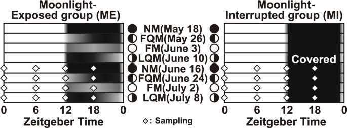

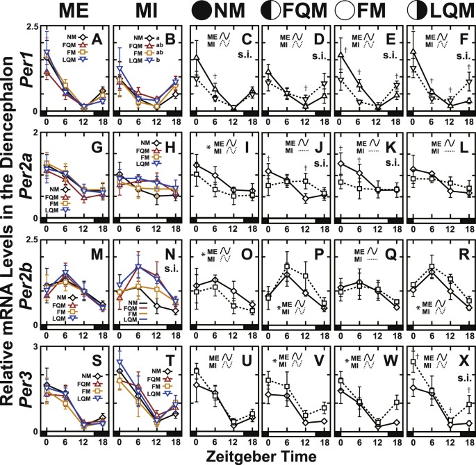

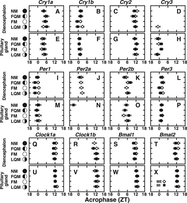
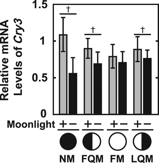
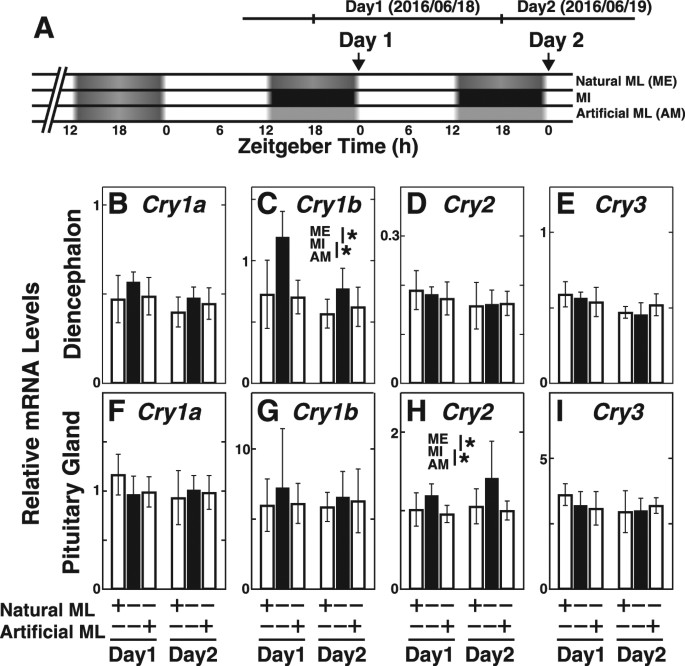


